XMM-Newton Data Files Handbook
74
XMM-Newton XMM-Newton Data Files Handbook XMM-PS-USR-MAN-0001 Issue 4.8 J.-U. Ness, M. Ehle M. Guainazzi & M. Santos-Lle´o December 27, 2017 Revision history Revision number Date Revision author Comments Issue 4.8 December 27, 2017 J.-U. Ness Add additional pipeline product Issue 4.7 May 10, 2017 J.-U. Ness Add additional pipeline products Issue 4.6 May 23, 2016 J.-U. Ness Add additional pipeline products Issue 4.5 February 15, 2016 J.-U. Ness Add Naming convention for Instr. Modes and Filters Issue 4.4 October 19, 2015 J.-U. Ness Update of Time Reference Frame in Appendix A. Issue 4.3 May 28, 2015 J.-U. Ness Incl. opt. GTI ext. for time filtering; new PPS product Issue 4.2 January 28, 2014 J.-U. Ness Include Mosaic ODFs, update PPS, update CCF Issue 4.1 January 28, 2011 J.-U. Ness Include descriptions of Slew and RadMon data Issue 4.0 September, 2009 J.-U. Ness Revised Public Release Issue 3.1 December, 2004 M. Guainazzi Fifth public Issue (with SAS 6.1) Issue 3.0.1 March 2004 M. Guainazzi Definition of Reconstructed Time Correlation added Issue 3.0 February 2004 M. Guainazzi Fourth public issue (with SAS 6.0) Issue 2.3 February, 2002 M. Guainazzi Third public issue (with SAS 5.3) Issue 2.2 June, 2001 M. Guainazzi Typo in the ODF file name convention corrected Issue 2.1 February, 2001 M. Guainazzi Update for the new content of data CD-ROMs Issue 2.0 January, 2001 M. Guainazzi Second public issue (with SAS 5.0) Issue 1.0 July, 2000 M. Guainazzi First public issue (with SAS 4.1) Draft 3.0 January, 2000 M. Guainazzi Third draft Draft 2.0 November, 1999 M. Guainazzi Second draft Draft 1.0 March, 1999 M.Santos-Lle´o First draft i
Transcript of XMM-Newton Data Files Handbook

XMM-Newton
XMM-Newton Data Files Handbook
XMM-PS-USR-MAN-0001
Issue 4.8
J.-U. Ness, M. Ehle
M. Guainazzi & M. Santos-Lleo
December 27, 2017
Revision history
Revision number Date Revision author Comments
Issue 4.8 December 27, 2017 J.-U. Ness Add additional pipeline productIssue 4.7 May 10, 2017 J.-U. Ness Add additional pipeline productsIssue 4.6 May 23, 2016 J.-U. Ness Add additional pipeline productsIssue 4.5 February 15, 2016 J.-U. Ness Add Naming convention for Instr. Modes and FiltersIssue 4.4 October 19, 2015 J.-U. Ness Update of Time Reference Frame in Appendix A.Issue 4.3 May 28, 2015 J.-U. Ness Incl. opt. GTI ext. for time filtering; new PPS productIssue 4.2 January 28, 2014 J.-U. Ness Include Mosaic ODFs, update PPS, update CCFIssue 4.1 January 28, 2011 J.-U. Ness Include descriptions of Slew and RadMon dataIssue 4.0 September, 2009 J.-U. Ness Revised Public ReleaseIssue 3.1 December, 2004 M. Guainazzi Fifth public Issue (with SAS 6.1)
Issue 3.0.1 March 2004 M. Guainazzi Definition of Reconstructed Time Correlation addedIssue 3.0 February 2004 M. Guainazzi Fourth public issue (with SAS 6.0)Issue 2.3 February, 2002 M. Guainazzi Third public issue (with SAS 5.3)Issue 2.2 June, 2001 M. Guainazzi Typo in the ODF file name convention correctedIssue 2.1 February, 2001 M. Guainazzi Update for the new content of data CD-ROMsIssue 2.0 January, 2001 M. Guainazzi Second public issue (with SAS 5.0)Issue 1.0 July, 2000 M. Guainazzi First public issue (with SAS 4.1)Draft 3.0 January, 2000 M. Guainazzi Third draftDraft 2.0 November, 1999 M. Guainazzi Second draftDraft 1.0 March, 1999 M. Santos-Lleo First draft
i

XMM-NewtonScience Operations Team
Document No.: XMM-PS-USR-MAN-0001Issue/Rev.: Issue 4.8Date: December 27, 2017Page: ii
Contents
1 Introduction 1
1.1 Purpose . . . . . . . . . . . . . . . . . . . . . . . . . . . . . . . . . . . . . . . . . 1
1.2 Document structure . . . . . . . . . . . . . . . . . . . . . . . . . . . . . . . . . . 1
1.3 A summary of the data flow . . . . . . . . . . . . . . . . . . . . . . . . . . . . . . 2
2 An overview of the XMM-Newton data file subsystems 3
2.1 The XMM-Newton Science Archive . . . . . . . . . . . . . . . . . . . . . . . . . . 5
3 File formats 6
3.1 FITS format . . . . . . . . . . . . . . . . . . . . . . . . . . . . . . . . . . . . . . 6
3.2 Portable Data Format (PDF) . . . . . . . . . . . . . . . . . . . . . . . . . . . . . 7
3.3 Portable Network Graphics (PNG) . . . . . . . . . . . . . . . . . . . . . . . . . . 7
3.4 HTML . . . . . . . . . . . . . . . . . . . . . . . . . . . . . . . . . . . . . . . . . . 7
3.5 ASCII . . . . . . . . . . . . . . . . . . . . . . . . . . . . . . . . . . . . . . . . . . 7
3.6 Compression . . . . . . . . . . . . . . . . . . . . . . . . . . . . . . . . . . . . . . 8
4 Uncalibrated files 9
4.1 Observation/Slew data science, non-science, and spacecraft files . . . . . . . . . . 9
4.1.1 Identification of individual ODF component files . . . . . . . . . . . . . . 10
4.1.2 Observation/slew summary file . . . . . . . . . . . . . . . . . . . . . . . . 12
4.1.3 EPIC MOS science files . . . . . . . . . . . . . . . . . . . . . . . . . . . . 13
4.1.3.1 EPIC MOS Imaging Mode Event List File . . . . . . . . . . . . 15
4.1.3.2 EPIC MOS Timing Mode Event List File . . . . . . . . . . . . . 15
4.1.3.3 EPIC MOS Auxiliary File . . . . . . . . . . . . . . . . . . . . . . 15
4.1.4 EPIC MOS diagnostics files . . . . . . . . . . . . . . . . . . . . . . . . . . 16
4.1.5 EPIC PN science files . . . . . . . . . . . . . . . . . . . . . . . . . . . . . 16
4.1.5.1 EPIC PN Imaging Mode Event List File . . . . . . . . . . . . . 17
4.1.5.2 EPIC PN Timing/Burst Mode Event List File . . . . . . . . . . 18
4.1.5.3 EPIC PN Auxiliary File . . . . . . . . . . . . . . . . . . . . . . . 18
4.1.6 RGS science files . . . . . . . . . . . . . . . . . . . . . . . . . . . . . . . . 18
4.1.6.1 RGS Spectroscopy Mode Event List File . . . . . . . . . . . . . 19
4.1.6.2 RGS High Time Resolution Mode Event List File . . . . . . . . 20
4.1.6.3 RGS Auxiliary File . . . . . . . . . . . . . . . . . . . . . . . . . 20
4.1.6.4 RGS Diagnostic Mode Image File . . . . . . . . . . . . . . . . . 20
4.1.6.5 RGS Offset Files . . . . . . . . . . . . . . . . . . . . . . . . . . . 22
4.1.7 OM science files . . . . . . . . . . . . . . . . . . . . . . . . . . . . . . . . 22

XMM-NewtonScience Operations Team
Document No.: XMM-PS-USR-MAN-0001Issue/Rev.: Issue 4.8Date: December 27, 2017Page: iii
4.1.7.1 OM Imaging Mode Data Image File . . . . . . . . . . . . . . . . 22
4.1.7.2 OM Fast Mode Event List File . . . . . . . . . . . . . . . . . . . 23
4.1.7.3 OM Tracking History Data Auxiliary File . . . . . . . . . . . . . 23
4.1.7.4 OM Reference Frame Data Auxiliary File . . . . . . . . . . . . . 23
4.1.7.5 “Priority files” . . . . . . . . . . . . . . . . . . . . . . . . . . . . 23
4.1.8 OM diagnostics files . . . . . . . . . . . . . . . . . . . . . . . . . . . . . . 25
4.1.9 EPIC Radiation Monitor science files . . . . . . . . . . . . . . . . . . . . . 26
4.1.9.1 ERM Count Rate Files . . . . . . . . . . . . . . . . . . . . . . . 27
4.1.9.2 ERM Spectra Files . . . . . . . . . . . . . . . . . . . . . . . . . 28
4.1.10 Instrument Housekeeping Files . . . . . . . . . . . . . . . . . . . . . . . . 29
4.1.11 Spacecraft files . . . . . . . . . . . . . . . . . . . . . . . . . . . . . . . . . 29
4.1.11.1 Spacecraft Time Correlation File . . . . . . . . . . . . . . . . . . 30
4.1.11.2 Spacecraft Attitude History File . . . . . . . . . . . . . . . . . . 30
4.1.11.3 Spacecraft Reconstructed Orbit File . . . . . . . . . . . . . . . . 30
4.1.11.4 Spacecraft Periodic Housekeeping File . . . . . . . . . . . . . . . 31
4.2 EPIC Radiation Monitor archive . . . . . . . . . . . . . . . . . . . . . . . . . . . 31
5 Calibration data: CCF 34
5.1 The Calibration Index File . . . . . . . . . . . . . . . . . . . . . . . . . . . . . . 34
5.2 File naming convention . . . . . . . . . . . . . . . . . . . . . . . . . . . . . . . . 34
5.3 File description . . . . . . . . . . . . . . . . . . . . . . . . . . . . . . . . . . . . . 36
5.3.1 Scope: xmm . . . . . . . . . . . . . . . . . . . . . . . . . . . . . . . . . . 36
5.3.2 Scope: xrt . . . . . . . . . . . . . . . . . . . . . . . . . . . . . . . . . . . . 37
5.3.3 Scope: emos . . . . . . . . . . . . . . . . . . . . . . . . . . . . . . . . . . . 37
5.3.4 Scope: epn . . . . . . . . . . . . . . . . . . . . . . . . . . . . . . . . . . . 38
5.3.5 Scope: rgs . . . . . . . . . . . . . . . . . . . . . . . . . . . . . . . . . . . . 40
5.3.6 Scope: om . . . . . . . . . . . . . . . . . . . . . . . . . . . . . . . . . . . . 41
6 Calibrated event lists 43
6.1 Event list structure in the MOS Imaging Mode . . . . . . . . . . . . . . . . . . . 43
6.2 Event list structure in the MOS Timing Mode . . . . . . . . . . . . . . . . . . . . 45
6.3 Event list structure in the PN Imaging Mode . . . . . . . . . . . . . . . . . . . . 46
6.4 Event list structure in the PN Timing Mode . . . . . . . . . . . . . . . . . . . . . 48
6.5 Event list structure in the RGS Spectroscopy Mode . . . . . . . . . . . . . . . . . 48
6.6 Event list structure in the RGS High Resolution Timing Mode . . . . . . . . . . 51
6.7 Event list structure in the OM Fast Mode . . . . . . . . . . . . . . . . . . . . . . 51
7 Instrument Mode and Filter names in XSA and file headers 53

XMM-NewtonScience Operations Team
Document No.: XMM-PS-USR-MAN-0001Issue/Rev.: Issue 4.8Date: December 27, 2017Page: iv
7.1 Scientific Modes . . . . . . . . . . . . . . . . . . . . . . . . . . . . . . . . . . . . 53
7.2 non-Scientific Modes . . . . . . . . . . . . . . . . . . . . . . . . . . . . . . . . . . 53
8 Pipeline data products: PPS 56
9 Acronym list 63
10 Glossary of binary table column descriptions 65
11 Acknowledgements 66
12 Reference documents 67
A Time scale and Reference Time 69
List of Tables
1 ODF/SDF component filenames . . . . . . . . . . . . . . . . . . . . . . . . . . . . 10
2 Binary table extension name(s) for the ODF/SDF files . . . . . . . . . . . . . . . 13
3 Values of the DATATYPE keywords for the MOS/PN science data file types . . . . 14
4 EPIC MOS Imaging Mode Event List file (*M[1,2]*IME.FIT) binary table columns 15
5 EPIC MOS Timing Mode Event List file (*M[1,2]*TIE.FIT) binary table columns 15
6 EPIC MOS Auxiliary file (*M[1,2]*AUX.FIT) Binary table columns . . . . . . . 16
7 EPIC PN Imaging Mode Event List file (*PN*IME.FIT) binary table columns . . 18
8 EPIC PN Timing/Burst Mode Event List file (*PN*TIEBUE.FIT) binary table columns 18
9 EPIC PN Auxiliary file (*PN*AUX.FIT) binary table columns for the extensionPNAUX1 . . . . . . . . . . . . . . . . . . . . . . . . . . . . . . . . . . . . . . . . . . 19
10 EPIC PN Auxiliary file (*PN*AUX.FIT) binary table columns for the extensionPNAUX2 . . . . . . . . . . . . . . . . . . . . . . . . . . . . . . . . . . . . . . . . . . 19
11 Values of the DATATYPE keywords for the RGS science data file types . . . . . . . 19
12 RGS Spectroscopy Mode Event List file (*R[1,2]*SPE.FIT) binary table columns . 20
13 RGS High Time Resolution Mode Event List file (*R[1,2]*HTE.FIT) binary tablecolumns . . . . . . . . . . . . . . . . . . . . . . . . . . . . . . . . . . . . . . . . . 20
14 RGS Auxiliary file (*R[1,2]*AUX.FIT) first binary table columns . . . . . . . . . 21
15 RGS Auxiliary file (*R[1,2]*AUX.FIT) second binary table columns . . . . . . . . 21
16 Values of the DATATYPE keywords for the OM science data file types . . . . . . . . 23
17 OM Fast Mode Event List file (*OM*FAE.FIT) binary table columns . . . . . . . 23
18 OM Tracking History Data Auxiliary file (*OM*THX.FIT) binary table columns 24
19 OM Reference Frame Auxiliary file (*OM*RFX.FIT) binary table columns . . . . 25
20 OM Priority Field Acquisition Auxiliary file (*OM*PAX.FIT) binary table columns 26

XMM-NewtonScience Operations Team
Document No.: XMM-PS-USR-MAN-0001Issue/Rev.: Issue 4.8Date: December 27, 2017Page: v
21 OM Priority Field Window Data Auxiliary file (*OM*WDX.FIT) binary tablecolumns . . . . . . . . . . . . . . . . . . . . . . . . . . . . . . . . . . . . . . . . . 27
22 OM Priority Fast Auxiliary file (*OM*PFX.FIT) binary table columns . . . . . . 28
23 ERM Count Rate files (*RM*ECX.FIT) binary table columns . . . . . . . . . . . 28
24 ERM Spectra files (*RM*ESX.FIT) binary table columns . . . . . . . . . . . . . . 29
25 Spacecraft Time Correlation file (*SC*TCS.FIT) binary table columns. The Re-constructed Time Correlation file (*SC*TCX.FIT) has the same columns plusthose in the bottom part. . . . . . . . . . . . . . . . . . . . . . . . . . . . . . . . . 31
26 Spacecraft Attitude History file (*SC*ATS.FIT) binary table columns . . . . . . . 32
27 Spacecraft Raw Attitude History file (*SC*RAS.ASC) ASCII table columns . . . 33
28 CIF binary extension columns . . . . . . . . . . . . . . . . . . . . . . . . . . . . . 35
29 Allowed scope identifiers . . . . . . . . . . . . . . . . . . . . . . . . . . . . . . . . 35
30 Calibration data types by scope. A ’+’ indicates that calibration files for the re-spective scope is present and is explained in Sect. 5.3 . . . . . . . . . . . . . . . . 35
31 MOS Imaging Mode event list column . . . . . . . . . . . . . . . . . . . . . . . . 44
32 PN Imaging Mode event list column . . . . . . . . . . . . . . . . . . . . . . . . . 47
33 RGS Spectroscopy Mode event list columns. The placeholders xy are readout node(x =0-1) and CCD number (y =1-9). . . . . . . . . . . . . . . . . . . . . . . . . . 49
34 OM Fast Mode event list column . . . . . . . . . . . . . . . . . . . . . . . . . . . 52
35 Naming of scientific instrument modes and filters in XSA and header keywords . 54
36 Naming of non-scientific instrument names and filters in XSA and *SUM.SAS file 55
37 Pipeline product filenames . . . . . . . . . . . . . . . . . . . . . . . . . . . . . . 56
38 Pipeline product files . . . . . . . . . . . . . . . . . . . . . . . . . . . . . . . . . . 60

XMM-NewtonScience Operations Team
Document No.: XMM-PS-USR-MAN-0001Issue/Rev.: Issue 4.8Date: December 27, 2017Page: 1
1 Introduction
1.1 Purpose
The purpose of this document is to provide a detailed description of the data that are distributedfrom the XMM-Newton Science Archive (XSA), which is part of the Science Control System(SCS) archive.
The handbook deals with the format and structure used to distribute data from the archive andwith the details of individual file contents. Instructions how to find and retrieve data from theXMM-Newton Science archive (XSA) and how to analyse the data with the Science AnalysisSubsystem (SAS) can be found in the corresponding documentation ([17] and [10]).
Users are referred to section 11 for a list of useful links and documents that provide all thenecessary information. In this document we use acronyms which are defined in section 9. Wedraw particular attention to the XMM-Newton Users Handbook (UHB), [16].
1.2 Document structure
Before individual files are described, a general introduction is given. The next section providesan overview to the different data subsystems, like the Observation Data Subsystem (ODS), thePipeline Processing Subsystem (PPS), which uses some specific SAS tasks and the XMM-NewtonScience Archive. Sect. 3 deals with the specification of the file formats.
The files are described in the order in which they are used in a systematic reduction, startingwith the uncalibrated data in Sect. 4, continuing with the files needed to calibrate these data inSect. 5, and then describing the calibrated events files in Sect. 6. In addition, the products fromthe Pipeline Processing Subsystem (PPS) are described in Sect. 8. Each of these sections beginswith an outline of the naming convention which allows identification of each file encountered inthe respective category.
The last three sections contain an acronym list and glossary, due acknowledgements, and a listof reference documents, respectively.
In Appendix A, the reference time system is explained.

XMM-NewtonScience Operations Team
Document No.: XMM-PS-USR-MAN-0001Issue/Rev.: Issue 4.8Date: December 27, 2017Page: 2
1.3 A summary of the data flow
The XMM-Newton payload operations are run by the Science Operations Centre (SOC) atthe European Space Astronomy Centre (ESAC) and include the pipeline data processing. TheXMM-Newton Pipeline Processing System (PPS) is based on a dedicated pipeline reducingdata from each of the EPIC, RGS and OM science instruments, using the same SAS softwarepackages that are available for users to interactively analyse XMM-Newton data. The pipelineinfrastructure used to carry out the processing has been developed by the Survey Science Centre(SSC) in Leicester, UK. Up to March 1st 2012, the SSC was responsible for systematicallyrunning and maintaining the pipeline, and processing responsibility was then transferred to theXMM-Newton SOC.
The SOC is responsible for all the services to the community associated with an observatory typescience mission like XMM-Newton. In particular, the XMM-Newton SOC uses the re-formattedtelemetry (Observation Data Files, ODF, and Slew Data Files, SDF) to generate pipeline datafrom the uncalibrated files (Sect. 4) and the Calibration Data (CCF, Sect. 5). The SOC archivesraw, auxiliary, and processed data and enables access to the Guest Observers (GOs) and, afterthe end of any proprietary period, to the entire scientific community. In addition, the SOC isresponsible for the calibration of the instruments and for the maintenance and optimisation ofthe Science Analysis Software (SAS), part of whose tasks are invoked by the PPS (Sect. 8).
The Mission Operation Centre (MOC), located at ESOC, Darmstadt, Germany, has the overallresponsibility for the XMM-Newton spacecraft operations.

XMM-NewtonScience Operations Team
Document No.: XMM-PS-USR-MAN-0001Issue/Rev.: Issue 4.8Date: December 27, 2017Page: 3
2 An overview of the XMM-Newton data file subsystems
The nomenclature used for activities performed by XMM-Newton is as follows: A proposal isa group of activities that pursue the same specific goal such as a science programme proposedby a Guest Observer (GO) or a calibration campaign proposed by an instrument team. Eachproposal consists of one or more observations within which there are several measurementswith different instruments, called exposures. An observation is defined to be the science dataand required auxiliary information collected during a continuous period of time and registeredunder a common indentifier. It usually contains data from all science instruments (EPIC, RGSand OM), but not necessarily.
In the vast majority of cases, XMM-Newton is pointing to a fixed position in the sky during anobservation. Exceptions are EPIC Mosaic, RGS Multipointing and slew observations. A slew isthe period of time elapsed during a single manoeuvre between two sky pointings, and the EPIC-pn remains open with the medium filter and the observing mode of the previous observation.XMM-Newton slews through the sky at ∼ 90 degrees/hour, which means that a source passesthrough the detector field-of-view in about 15 seconds. Only the EPIC-pn camera allows slewsources to be imaged essentially as point sources while the EPIC-MOS cameras detects sourcesas streaks in the sky. The slew catalog therefore concentrates only on EPIC-pn data and ignoresdata taken in small window or timing mode. EPIC mosaic observations consist of several skypointings with different coordinates during which data are continuously taken with the X-raycameras. RGS multipointing observations consist of five pointings with slightly different skypositions for better sampling of the RGS spectra.
The time interval between the start and the end time of an observation is called the duration ofthe observation. In turn, an observation consists of a sequence of one or more exposures for eachinstrument. For an individual instrument, exposures form a non-overlapping sequence. Duringan exposure, the commanded state of the individual instrument is unchanged, no changes indata acquisition mode or filter (if applicable) occur, and the data thus have a fixed format. Anexposure is necessarily a concept which refers to a single individual instrument.
For each observation period (i.e., the period of time from the start of configuring the spacecraftand instruments for an observation until the end of the observation) or per slew period, a set offiles is produced by the XMM-Newton Observation Data Subsystem (ODS). The ODS providesthe facilities necessary to accept all inputs needed for the generation of the Observation Data File(ODF) and Slew Data File (SDF). These terms stand for a set of files generated for each specificobservation or slew, respectively. They are stored in a single directory for each observation orslew and contain data from all operative instruments. Basically, their component files containraw, uncalibrated science data from each active instrument mode and spacecraft informationdata.
Each ODF requires several components:
1. Spacecraft and science telemetry
2. Reconstructed attitude data
3. Reconstructed orbit data
For EPIC mosaic observations, the ODS creates a single ODF for the entire observation, outof which additional separate ODFs have been produced. These ”pseudo ODFs” follow the sameformat as ODFs produced by the ODS. The coordinates quoted for each of the ”pseudo ODFs”

XMM-NewtonScience Operations Team
Document No.: XMM-PS-USR-MAN-0001Issue/Rev.: Issue 4.8Date: December 27, 2017Page: 4
are the central coordinates of that pointing in the sequence. The contents are the normal ODFdata corresponding solely to the observation during the time that pointing was stable. Typically,there is one exposure per instrument per pointing, except for OM, where several exposures couldhave been taken within a single pointing. ”Pseudo ODFs” can be recognised by the file namesas shown in Sect. 4.1.1.
All scientific data included in the ODF/SDF (including the pseudo ODFs for mosaic obser-vations) are systematically and automatically analysed by the Processing Pipeline Subsystem(PPS), and PPS products are generated for each instrument mode, using some specific SAStasks.
The collection of calibration files necessary to reduce and analyse the data collected with thescientific payload of XMM-Newton is called Current Calibration File (CCF). A CCF containsall the calibration files ever created. The reason for keeping all files is that a given observationdoes not necessarily have to be calibrated with the last calibration files, but oftentimes with thefiles that are nearest in time to the time of the observation. Each file contains a time stamp toindicate the particular time for which it is valid.
For most purposes the PPS treats individual exposures separately, most PPS products arederived from data taken during a single exposure. However, there are some significant exceptions:all EPIC exposures are input to a joint source detection process; OM source information fromdifferent exposures are combined to provide colour information; potential OM counterpartsto EPIC sources are identified; the RGS zero order position is determined from the EPICsource location. EPIC source lists are cross-correlated with multiwavelength archival data inthe Archival Catalogue and Database Subsystem (ACDS) at the Observatoire Astronomique deStrasbourg (OAS).
The EPIC Radiation Monitor (ERM) is used for detailed monitoring of the space radiativeenvironment, constituting a reference for the development of detectors to be used in futuremissions. ERM data could also be useful to define good-time intervals. Calibrated ERM datacan be produced with SAS, version 9 or higher (see SAS manual for details) and will be includedas part of the PPS products.

XMM-NewtonScience Operations Team
Document No.: XMM-PS-USR-MAN-0001Issue/Rev.: Issue 4.8Date: December 27, 2017Page: 5
2.1 The XMM-Newton Science Archive
All data resulting from or pertinent to a given observation are archived, catalogued and linkedin the XMM-Newton Science Archive (XSA):http://www.cosmos.esa.int/web/xmm-newton/xsa
All relevant files, from the proposal abstract up to the processed data, catalogues and publica-tions are stored and can easily be retrieved by means of a web based interfacehttp://nxsa.esac.esa.int/nxsa-web/#search
The data can also be retrieved directly via the AIOhttp://nxsa.esac.esa.int/nxsa-web/#aio
The XSA archive constitutes the main interface to the scientific community. Alongside ODFsand PPS data products for all performed XMM-Newton pointed and slew observations, the XSAcontains a wide range of information, such as:
• Links to Catalogues: http://www.cosmos.esa.int/web/xmm-newton/xsa/#download
1. The XMM-Newton Serendipitous Source Catalogues
2. The XMM-Newton Slew survey source catalogue
3. The XMM-OM source catalogue
• Images, spectra and light curves that can be displayed with ds9 or with Aladin
• For each observation, access to refereed publications using the data, via a link tothe SAO/NASA Astrophysics Data System (ADS)
• Access to proposal information (science abstract, instrument configuration)
• Links to XMM-Newton documentationhttp://www.cosmos.esa.int/web/xmm-newton/documentation
• Link to EPIC Radiation Monitor data files
http://www.cosmos.esa.int/web/xmm-newton/radmon-details
For access to the XSA and download of files see the XSA web page:http://www.cosmos.esa.int/web/xmm-newton/xsa

XMM-NewtonScience Operations Team
Document No.: XMM-PS-USR-MAN-0001Issue/Rev.: Issue 4.8Date: December 27, 2017Page: 6
3 File formats
The majority of science data are stored in “Flexible Image Transport System” (FITS) format,with a few exceptions that are either ASCII or HTML files or in common display formats (e.g.,PDF, PNG).
3.1 FITS format
All of the ODF/SDF component files, with the exception of the summary files, reconstructedorbit file, and raw attitude file, are FITS files and conform to the FITS standard. A descriptionof the FITS format can be found in [5], which is accessible also at the URLhttp://fits.gsfc.nasa.gov/
The calibration files and the bulk of the PPS products also conform to the FITS standard.Wherever possible and desirable the calibration files and the PPS products follow the conventionsof the OGIP (Office of Guest Investigator Programs) FITS working group. The HEASARC FITSWorking Group activities are described at the following URL:http://heasarc.gsfc.nasa.gov/docs/heasarc/ofwg/ofwg intro.html
For FITS files where OGIP FITS standards are not applicable or available, new standards closelyfollowing the OGIP approach are used.
The FITS format is primarily designed to store scientific data sets consisting of multidimensionalarrays (1-D spectra, 2-D images or 3-D data cubes) and 2-dimensional tables containing rowsand columns of data. A FITS data file is composed of a sequence of Header + Data Units(HDUs).
The general structure of a FITS file is as follows:
• a primary header;
• a primary data array of zero length;
• zero or more extensions
Each extension consists of an extension header and a data section. Extensions are named andcan appear in any order. Only the following FITS extensions are used:
• ASCII table: XTENSION=TABLE
• binary table: XTENSION=BINTABLE
• image: XTENSION=IMAGE
The header consists of keyword=value statements, which describe the organisation of the datain the HDU and the format of the contents. It may also provide additional information, forexample, about instrument status or the history of the data. The following block contains thedata, which are structured as specified in the header. The data section of the HDU may containa digital image, a table or a multidimensional matrix that is not an image. An HDU need notcontain data.

XMM-NewtonScience Operations Team
Document No.: XMM-PS-USR-MAN-0001Issue/Rev.: Issue 4.8Date: December 27, 2017Page: 7
3.2 Portable Data Format (PDF)
Intrinsically compressed PDF files are used for the display of line graphics. In some cases, thesegraphics files are derived, at least in part, from product files in FITS format. In these casesthe PDF file is significantly smaller than the FITS file and/or contains annotations providing auser-friendly summary of the FITS file.
3.3 Portable Network Graphics (PNG)
Portable Network Graphics (PNG) format (see the PNG home page at the following URLhttp://libpng.org/pub/png) is used for the display of pixel images in the PPS products.PNG is an extensible file format for the loss-less, portable, well-compressed storage of images.PNG provides a patent-free replacement for GIF as the graphics file format of choice and canalso replace many common uses of TIFF. Indexed-colour, grey-scale, and true-colour images aresupported, plus an optional alpha channel for transparency. Sample depths range from 1 to 16bits.
As with PDF graphics, in some cases, PNG graphics files are derived, at least in part, from PPSproduct files in FITS format. In these cases the PNG files are significantly smaller than theirFITS files and/or contain annotations providing a user-friendly summary of the FITS file.
3.4 HTML
HTML is the standard format for files which provides overview or summary-type text informationfor PPS products. Important PPS results are not only presented in HTML files, and thus someinformation may be found in more than one type of file.
HTML files offer the possibility to provide structure to the collected PPS products of an ob-servation through the use of hyperlinks. Web browsers can then provide a useful interface tothe products. Links within the PPS products point to both external and internal services (oruniform resource locators, i.e., URLs)
• External URLs: URLs to external sites are limited to links to the SIMBAD family ofservers only [for which the Centre de Donnees astronomiques de Strasbourg (CDS)ensures support throughout the life of the SSC]. These links provide reference dataonly, they do not provide access to bulk data.
• Internal URLs: internal links are those pointing to pipeline products within thepps directory. Its use provides a quick and user-friendly mechanism for navigatingaround a product set (i.e., those belonging to a single ODF or SDF).
Within a PPS product set HTML internal links are self-contained, i.e., apart from the externalURLs described, there are no link destinations outside of the product set.
3.5 ASCII
ASCII files are used to present script and some tabular information. In particular, eachODF/SDF contains a single summary file, with a summary of the information relating to theobservation or slew (see Sect. 4.1).

XMM-NewtonScience Operations Team
Document No.: XMM-PS-USR-MAN-0001Issue/Rev.: Issue 4.8Date: December 27, 2017Page: 8
3.6 Compression
With few exceptions, all PPS products are supplied in compressed form, that is, each productis individually compressed using the Unix command gzip. The exceptions are:
• PNG product files. PNG is already an intrinsically compressed format.
• PDF product files. These are created intrinsically compressed.
• PPS run message product files, that are (small) ASCII files.
• HTML files. Browsers do not understand gzipped HTML files.
Note that fits file viewers like fv or ds9, as well as the SAS tasks can work on compressed FITSfiles, and it is therefore not necessary to uncompress. However, for very large files, the SAStasks run significantly faster if the files are uncompressed beforehand.

XMM-NewtonScience Operations Team
Document No.: XMM-PS-USR-MAN-0001Issue/Rev.: Issue 4.8Date: December 27, 2017Page: 9
4 Uncalibrated files
4.1 Observation/Slew data science, non-science, and spacecraft files
This section gives a basic description of the ODF/SDF component files for pointed and slewobservations, respectively. The full information and details can be found in the ODF/SDFInterface Control Document [6]. There are six categories of ODF/SDF component files:
• Instrument science files are all files directly related to the scheduled observation timeperiod. No calibration of the science telemetry is performed before it is stored in theinstrument science files. The science parameters are extracted from the telemetrypackets and stored in their raw form with, in general, no further processing beingperformed. If additional processing is required in order to generate an instrumentscience file, additional descriptions can be found in the relevant sections.
• Diagnostics files created during calibration observations
• Instrument housekeeping files:
– Instrument periodic housekeeping files contain the calibrated instrument peri-odic housekeeping parameters and instrument-related derived parameters. Theperiodic housekeeping parameters are extracted from the telemetry packets andthe derived parameters calculated. The parameters are then calibrated usingthe applicable calibration curves (as defined in the XMM-Newton telemetrydata base) and stored, with the corresponding time key, in the relevant instru-ment periodic housekeeping file.
– Instrument non-periodic housekeeping files
• Spacecraft files containing information of spacecraft attitude, orbit, housekeeping,and time conversion.
• EPIC Radiation Monitor (ERM) observation/slew period files. These are ERMscience files which correspond to observation and slew periods. The ERM data arepartitioned to correspond to observation and slew periods (see Sect. 4.1.9).
• ASCII Summary files, which contain a summary of the information relating to theobservation or slew.
All the above files, except the Summary files (Sect. 4.1.2), the raw attitude file (Sect. 4.1.11.2),and the reconstructed orbit file (Sect. 4.1.11.3), are in FITS format. They come in two flavors:binary table files or image files. There are three types of binary table files, event lists, auxiliaryfiles, and housekeeping files. An event list contains all the events detected in a specific CCD(EPIC, RGS) or defined window (OM). One file per exposure is defined. An auxiliary file con-tains frame/cycle information, plus other general information, generated by the CCD that wasactive during an exposure/observation, or bookkeeping information generated by the on-boardsoftware. A housekeeping file contains the calibrated instrument housekeeping parameters andinstrument-related derived parameters. An ODF/SDF image file consists of a primary headerunit, a primary data unit of zero length and one image extension HDU (see Sect. 3).

XMM-NewtonScience Operations Team
Document No.: XMM-PS-USR-MAN-0001Issue/Rev.: Issue 4.8Date: December 27, 2017Page: 10
All the ODF/SDF files share a common primary header. The headers of the binary or imageextensions of the other ODF/SDF files differ from each other, although sharing a set of commonkeywords (see [6]). For each header value an explanation is given next to the value in the header.
The ODF/SDF constituent files are described in the following sections, most of which are self-explanatory. Short descriptions of a few files are given in Sect. 10.
4.1.1 Identification of individual ODF component files
A typical ODF/SDF directory contains several dozens of files. The purpose of each file can beidentified from a combination of file name and content of the FITS header.
The filenames associated with ODFs and SDFs consist of up to 27 characters, followed by a ’.’(dot), followed by 3 characters. All characters are upper case. The adopted naming conventionis as follows:
rrrr obsidentif iiueeeccmmf.zzz
This encoding uniquely specifies the instrument, the type of observation (scheduled or unsched-uled), the exposure number, the CCD/OM window identifier, the file type, and the format.Descriptions of the each filename field are listed in Table 1.
Table 1: ODF/SDF component filenames
Field Description
rrrr The revolution (orbit) number
obsidentif The observation identifier, 10 digit: ppppppooll
pppppp the identifier of the proposal that contains the obs.oo identifier of the observations within the proposalll extended identifier (usually 01)Notes: For slews the first of the six p is ’9’
For pseudo ODF components of mosaic pointings, the values of ll
assume values (30+x), where x is the number of the mosaic pointing.
ii The instrument, or data source, identifierOM optical monitorR1 RGS-1R2 RGS-2M1 EPIC MOS-1M2 EPIC MOS-2PN EPIC PNRM EPIC radiation monitorSC Spacecraft
u
S Indicates that the observation was scheduledU Indicates that the observation was unscheduledX not applicable (because not science files)
eee The exposure number within the observation

XMM-NewtonScience Operations Team
Document No.: XMM-PS-USR-MAN-0001Issue/Rev.: Issue 4.8Date: December 27, 2017Page: 11
000 file does not correspond to an exposure period9xx is used for diagnostic Q dumps (RGS spectroscopy+Q)
cc The CCD identifier/OM Window identifier (2 digits)EPIC MOS CCD number (1-7) & CCD read-out mode (0,1)EPIC PN CCD number (01–12)RGS CCD number (01–09)Note: “00” is used for multi-CCD filesOM science window identifier
00 used for those files not having a corresponding CCD or science window
mm The data contained within the file nameAT Spacecraft attitudeAU EPIC or RGS auxiliaryBU EPIC PN burstCC EPIC counting cycle report (auxiliary file)CI EPIC MOS compressed timingD1 DPP non-periodic HousekeepingD2 DPP non-periodic HousekeepingDI EPIC MOS or RGS diagnosticDL EPIC PN discarded lines dataDP RGS Digital Pre-Processor non periodic housekeepingEC EPIC MOS extra heating configuration non-periodic housekeeping (if ii=M1 or M2)EC EPIC Radiation Monitor (ERC) count rate (if ii=RM)En OM engineering where n = 1 − 7ES EPIC Radiation Monitor (ERC) spectraFA OM fastHB EPIC high bit rate interface buffer size non-periodic housekeepingHC EPIC high bit rate interface configuration non-periodic housekeepingHT EPIC MOS high bit rate interface threshold values non-periodic housekeepingHT RGS high time resolutionIM EPIC or OM imagingNO EPIC PN noise dataNP OM non-periodic housekeepingOF RGS offset fileOD EPIC PN offset dataOV EPIC MOS offset / varianceP1 Spacecraft housekeeping 1 periodic housekeepingP2 Spacecraft housekeeping 2 periodic housekeepingP3 Spacecraft Attitude 1 periodic housekeepingP4 Spacecraft Attitude 2 periodic housekeepingP5 Spacecraft SYS HK SID0 periodic housekeepingP6 Spacecraft SYS HK SID1 periodic housekeepingP7 Spacecraft SYS HK SID4 periodic housekeepingP8 Spacecraft SYS HK SID5 periodic housekeeping

XMM-NewtonScience Operations Team
Document No.: XMM-PS-USR-MAN-0001Issue/Rev.: Issue 4.8Date: December 27, 2017Page: 12
P9 Spacecraft SYS HK SID6 periodic housekeepingPA EPIC PN additional periodic housekeepingPA OM priority field acquisition (auxiliary file)PC RGS CCD temperature periodic housekeepingPF RGS full periodic housekeepingPF OM priority fast (auxiliary file)PM EPIC PN main periodic housekeepingPT EPIC MOS bright pixel table non-periodic housekeepingPE EPIC MOS or OM periodic housekeepingRA Raw Attitude fileRF OM reference frame (auxiliary file)RI EPIC MOS reduced imagingRO Spacecraft reconstructed orbitSP RGS spectroscopySU Summary informationTC Spacecraft time correlationTH OM tracking history (auxiliary file)TI EPIC timingTM EPIC thermal monitoring limits non-periodic housekeepingWD OM priority window data (auxiliary file)
f The file typeE event list fileI image fileX auxiliary fileH housekeepingS spacecraftM summary
zzz File format (3 characters)ASC ASCII fileASZ Compressed ASCII fileFIT FITS fileFTZ Compressed FITS fileSAS SAS output (not original ODF constituents)
The nature of science ODF/SDF FITS files can also be identified by inspection of the value of therespective binary table(s) extension. This coding is described in Table 2. The Unix conventionto indicate multiple files is used; e.g.: M[1,2]IME1 means M1IME1 (MOS1) and M2IME1 (MOS2).
Finally, the nature of a file can also be identified by the value of the keyword DATATYPE in thebinary table header (see Table 3), although in this case only the file type can be unambiguouslydetermined, whereas a degeneracy in the instrument remains.
As mentioned above, the housekeeping files cannot always be uniquely distinguished from theirbinary table extension. However, they can still be recognised by their file names.
4.1.2 Observation/slew summary file
Each ODF and SDF contains a summary file in ASCII format (*SUM.ASC). The summary fileis structured in blocks, each containing the following information:

XMM-NewtonScience Operations Team
Document No.: XMM-PS-USR-MAN-0001Issue/Rev.: Issue 4.8Date: December 27, 2017Page: 13
Table 2: Binary table extension name(s) for the ODF/SDF files
File type BINTABLE . . .
MOS Imaging Mode Event List File M[1,2]IME1
MOS Timing Mode Event List File M[1,2]TIE1
MOS Auxiliary File M[1,2]AUX1
MOS Periodic Housekeeping File PERIODIC HK
PN Imaging Mode Event List File PNIME1
PN Timing Mode Event List File PNTIE1
PN Burst Mode PNBUE1
PN Auxiliary File (first extension) PNAUX1
PN Auxiliary File (second extension) PNAUX2
PN Housekeeping (first file) PERIODIC HK
PN Housekeeping (second file) MAIN PERIODIC
RGS Spectroscopy Mode Event List File R[1,2]SPE1
RGS High Time Resolution Event List File R[1,2]HTE1
RGS Auxiliary File (first extension) R[1,2]AUX1
RGS Auxiliary File (second extension) R[1,2]AUX2
RGS Periodic Housekeeping Files PERIODIC HK
OM Imaging Mode Image File OMIMI1
OM Fast Mode Event List File OMFAE1
OM Tracking History Data Auxiliary file OMTHX1
OM Reference Frame Auxiliary File OMRFX1
OM Periodic Housekeeping File OMPEH1
OM Non-Periodic Housekeeping File OMNPH1
Spacecraft Attitude History File SCATS1
Spacecraft Time Correlation File SCTSC1
• OBSERVATION: Observation/slew information, revolution number, scheduled Start/Stoptimes
• FILE: List of all ODF constituent files with short descriptions
• CONFIGURATION: Configuration details (ODF version, prime instrument)
• PROPOSAL: Proposal summary (PI name and address, proposal type, target name,exposure time, target and boresight coordinates, position angle)
• DATA QUALITY: Quality information (one block for each exposure)
A detailed description of the summary file can be found in [6]. In addition, a SAS summaryfile (*SUM.SAS) is produced by the SAS task odfingest that is usually written into the ODFdirectory, but is not a standard ODF constituent.
4.1.3 EPIC MOS science files
The following EPIC MOS Science Files are defined:
XMM-NewtonScience Operations Team
Document No.: XMM-PS-USR-MAN-0001Issue/Rev.: Issue 4.8Date: December 27, 2017Page: 14
1. Imaging Mode Event List Files (*M[1,2]*IME.FIT)
2. Timing Mode Event List Files (*M[1,2]*TIE.FIT)
3. Auxiliary Files (*M[1,2]*AUX.FIT)
4. Counting Cycle Report Auxiliary Files (*M[1,2]*CCX.FIT)
5. Offset/variance Mode Event List Files (*M1[1,2]*OVE.FIT)
These are all binary table files. For standard analysis, only types 1–3 are needed. Their contentwill be described below. Counting Cycle reports (type 4) will be included if the MOS telemetryis exceeded periodically during the observation. The cycle reports should already correspondwith Bad Time Intervals, but the data contained indicate the fraction of events detected butlost in the on-board processing. Therefore, the information included in these files may be usefulfor detailed timing analysis. Offset files (type 5) are down-linked confirmation that the CCDZero Bias signal level were applied.
We note that the above files do not map one-to-one with the instrument modes defined in [16].In particular:
• the “Full Window” and “Small Window” (aka “Partial Window”) instrumentalmodes produce Imaging Mode Event List Files only. If the latter is used, the sen-sitive area of the central chip (CCD1) is reduced. The other CCDs still produceImaging Mode Event Lists Files for the full 600×600 pixels area.
• the “Timing” instrumental mode produces both Image Mode Event List (in CCDs2–7) and Timing Mode Event List files (from central CCD1)
• Auxiliary files are produced for every instrumental mode
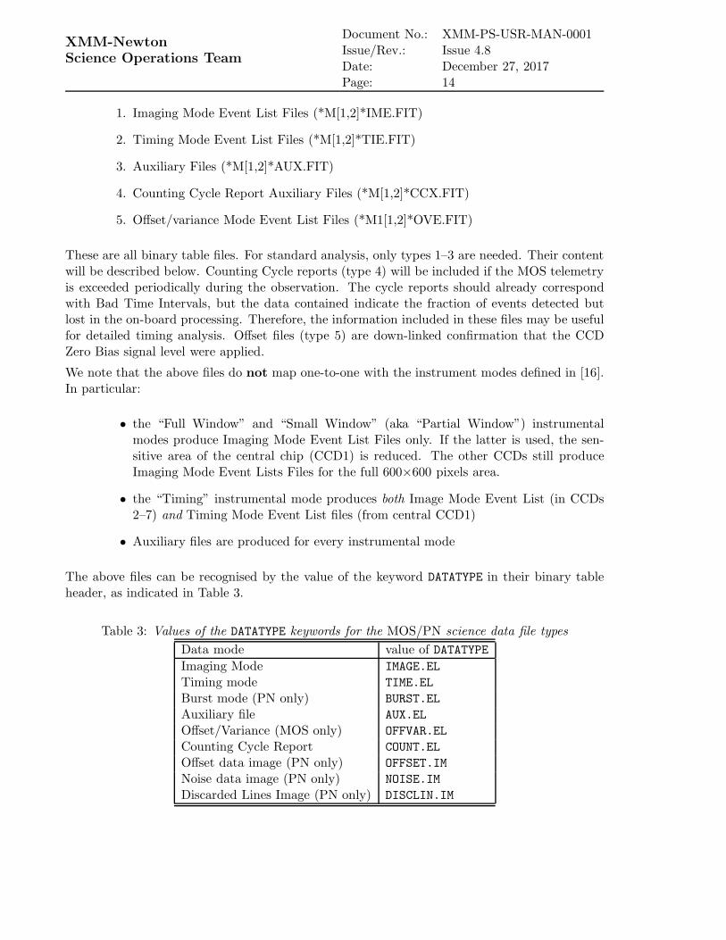
The above files can be recognised by the value of the keyword DATATYPE in their binary tableheader, as indicated in Table 3.
Table 3: Values of the DATATYPE keywords for the MOS/PN science data file types
Data mode value of DATATYPE
Imaging Mode IMAGE.EL
Timing mode TIME.EL
Burst mode (PN only) BURST.EL
Auxiliary file AUX.EL
Offset/Variance (MOS only) OFFVAR.EL
Counting Cycle Report COUNT.EL
Offset data image (PN only) OFFSET.IM
Noise data image (PN only) NOISE.IM
Discarded Lines Image (PN only) DISCLIN.IM

XMM-NewtonScience Operations Team
Document No.: XMM-PS-USR-MAN-0001Issue/Rev.: Issue 4.8Date: December 27, 2017Page: 15
4.1.3.1 EPIC MOS Imaging Mode Event List File
An EPIC MOS Imaging Mode Event List file (*M[1,2]*IME.FIT) is created for each CCD nodewhich is producing imaging mode data. Each file consists of a single binary table. The binarytable consists of the columns listed in Table 4.
Table 4: EPIC MOS Imaging Mode Event List file (*M[1,2]*IME.FIT) binary table columns
Name Typea Units Description
FRAME 1J COUNTER Frame numberRAWX 1I PIXEL Event raw X positionRAWY 1I PIXEL Event Y positionENERGYE1 1I CHANNEL Event energy (E1)ENERGYE2 1I CHANNEL Event energy (E2)ENERGYE3 1I CHANNEL Event energy (E3)ENERGYE4 1I CHANNEL Event energy (E4)PATTERN 1B Pattern numberPERIPIX 1B Peripheral pixels above Threshold Counter
aSee Sect. 9 for convention
4.1.3.2 EPIC MOS Timing Mode Event List File
An EPIC MOS Timing Mode Event List file (*M[1,2]*TIE.FIT) is created for each CCD nodewhich is producing timing mode data. Each file consists of a single binary table. The binarytable consists of the columns listed in Table 5.
Table 5: EPIC MOS Timing Mode Event List file (*M[1,2]*TIE.FIT) binary table columns
Name Typea Units Description
FRAME 1J COUNTER Frame numberRAWX 1I PIXEL Event raw X positionRAWY 1I PIXEL Event Y positionENGYE1E2 1I CHANNEL Event energy (E1+E2)PATTERN 1B Pattern numberPERIPIX 1B Peripheral pixels above Threshold Counter
aSee Sect. 9 for convention
4.1.3.3 EPIC MOS Auxiliary File
An EPIC MOS Auxiliary file (*M[1,2]*AUX.FIT) is created for each exposure in which at leastone CCD node is producing either timing or imaging mode data. Each file consists of a singlebinary table. A single file per observation is created, where each row is labelled according tothe relevant frame and CCD. The binary table consists of the columns listed in Table 6.

XMM-NewtonScience Operations Team
Document No.: XMM-PS-USR-MAN-0001Issue/Rev.: Issue 4.8Date: December 27, 2017Page: 16
Table 6: EPIC MOS Auxiliary file (*M[1,2]*AUX.FIT) Binary table columns
Name Typea Units Description
FRAME 1J COUNTER Frame numberCCDID 1B CCD identifierCCDNODE 1B CCD node identifierFTCOARSE 1I SECOND Coarse frame timeFTFINE 1I 40µs Fine time frameNPIXEL 1J PIXEL Pixel countNVALID 1I COUNTS No. of valid eventsNBELOW 1I COUNTS No. of events rejected by lower thresholdingNABOVE 1I COUNTS No. of events rejected by upper thresholdingGATTIFLG 1B Gatti flagFIFOOVF 1B FIFO Overflow Flag
aSee Sect. 9 for convention
4.1.4 EPIC MOS diagnostics files
For non-science mode observations, e.g., calibration observations, Diagnostic Mode Image Filesfiles (files by name *M[1,2]*DII.FIT; see Table 1) are created that can not be found in standardODF directories. The diagnostic files are binary images of Cal-closed observations without anycorrection (e.g., cosmic rays are not removed). They are equivalent to a dark-current observationand are used to produce the detector offset maps.
4.1.5 EPIC PN science files
The following EPIC PN Science Files are defined:
1. Imaging Mode Event List Files (*PN*IME.FIT)
2. Timing Mode Event List Files (*PN*TIE.FIT)
3. Burst Mode Event List Files (*PN*BUE.FIT)
4. Auxiliary Files (*PN*AUX.FIT)
5. Offset Data Image Files (*PN*ODI.FIT)
6. Noise Data Image Files (*PN*NOI.FIT)
7. Discarded Lines Image Files (*PN*DLI.FIT)
8. Counting Cycle Report Auxiliary Files (*PN*CCX.FIT)
These are all binary table files. All except type 6 are used in the standard data analysis. Thecontent of types 1–4 will be described below.
Type 5 (Offset Data Image) files contain the offset maps taken on board at the start of eachexposure. The offset maps contain the per pixel energy offsets for each active CCD of the

XMM-NewtonScience Operations Team
Document No.: XMM-PS-USR-MAN-0001Issue/Rev.: Issue 4.8Date: December 27, 2017Page: 17
configured mode; during the exposure, these offsets are subtracted on board from the measuredsignals.
Type 6 (Noise Data Image) files are used for diagnostic purposes and are not required forstandard data analysis. They contain the per pixel offset variance.
Type 7 (Discarded Lines Image) files are present in those cases where cosmic rays have hit aPN CCDs. They contain information on the number of lines blanked as a result of a detectedcosmic ray interaction.
Type 8 (Counting Cycle Report) auxiliary files provide a summary record of the data lost whenthe telemetry rate is exceeded by the data rate produced by the PN cameras (i.e., when the PNis operated in so-called Counting Mode).
Types 7 and 8 are required in the standard data reduction for a proper exposure correction.
As for the other XMM-Newton instruments, the PN ODF files do not explicitly contain acolumn TIME. PN imaging, timing and burst modes contain a ”Frame Counter”, that incrementsmonotonically in steps of 1 for the full detector. The ODF/SDF contain no time information inUT units, this has to be calculated using the time correlation file.
It is important to note that the above modes do not map one-to-one with the instrument modesdefined in [16]. In particular:
• the “Full Window”, “Large Window”, and “Small Window” instrumental modesproduce Imaging Mode Event List Files. While in Full and Large Window, allCCDs are used (for Large Window only half of the area of each chip is read out),only a part of CCD4 is used in Small Window.
• the “Timing” instrumental mode produces Timing Mode Event List data (from onechip). In the timing mode, imaging is made only in one dimension, along the column(RAWX) axis. Along the row direction (RAWY axis), data from a predefined areaon one CCD chip are collapsed into a one-dimensional row to be read out at highspeed. The RAWY axis is thus not a spatial coordinate, but is equivalent to time.
• A special flavour of the timing mode of the PN is the “burst” mode, which offershigh time resolution of 7µs, but has a low duty cycle of 3%.
• Auxiliary files are produced for every instrumental mode
The above files can be recognised by the value of the keyword DATATYPE in their binary tableheader, as indicated in Table 3.
4.1.5.1 EPIC PN Imaging Mode Event List File
An EPIC PN Imaging Mode Event List file (*PN*IME.FIT) is created for each CCD node whichis producing imaging mode data. Each file consists of a single binary table. The header keywordF1291 that can only be found for Full Frame observations, allows discrimination between ”FullFrame” (0) and ”Extended Full Frame” (3) Modes. The binary table consists of the columnslisted in Table 7.

XMM-NewtonScience Operations Team
Document No.: XMM-PS-USR-MAN-0001Issue/Rev.: Issue 4.8Date: December 27, 2017Page: 18
Table 7: EPIC PN Imaging Mode Event List file (*PN*IME.FIT) binary table columns
Name Typea Units Description
FRAME 1J COUNTER Frame numberRAWX 1I PIXEL Event raw X positionRAWY 1I PIXEL Event Y positionENERGY 1I CHANNEL Event energy
aSee Sect. 9 for convention
4.1.5.2 EPIC PN Timing/Burst Mode Event List File
EPIC PN Timing/Burst Mode Event List files (*PN*TIEBUE.FIT) are created for each CCD node
which is producing timing/burst mode data. Each file consists of a single binary table. Thebinary table consists of the columns listed in Table 8.
Table 8: EPIC PN Timing/Burst Mode Event List file (*PN*TIEBUE.FIT) binary table columns
Name Typea Units Description
FRAME 1J COUNTER Frame numberRAWX 1I PIXEL Event raw X positionRAWY 1I PIXEL Event Y positionENERGY 1I CHANNEL Event energy
aSee Sect. 9 for convention
4.1.5.3 EPIC PN Auxiliary File
An EPIC PN Auxiliary file (*PN*AUX.FIT) is created for each exposure in which at least oneCCD node is producing either timing or imaging mode data. Each file consists of two binarytables:
1. the first extension contains the frame information for all the active CCDs (see Ap-pendix A.2 of [6] for a description of the relevant algorithm)
2. the second extension contains the statistical information which is produced by eachquadrant after a certain number of cycles (see Appendix A.2 of [6] for a descriptionof the relevant algorithm).
A single file per observation is created, where each row is labelled according to the relevant frameand CCD identifier (in the first extension). The binary tables consist of the columns listed inTable 9 and Table 10, respectively.
4.1.6 RGS science files
The following RGS Science Files are defined:
1. Spectroscopy Mode Event List Files (*R[1,2]*SPE.FIT)

XMM-NewtonScience Operations Team
Document No.: XMM-PS-USR-MAN-0001Issue/Rev.: Issue 4.8Date: December 27, 2017Page: 19
Table 9: EPIC PN Auxiliary file (*PN*AUX.FIT) binary table columns for the extension PNAUX1
Name Typea Units Description
FRAME 1J COUNTER Frame numberCYCLE 1J COUNTER Cycle IdentifierFTCOARSE 1I SECOND Coarse frame timeFTFINE 1I 20.48 µs Fine time frameQUADRANT 1B Quadrant identifierCCDID 1B CCD identifier
aSee Sect. 9 for convention
Table 10: EPIC PN Auxiliary file (*PN*AUX.FIT) binary table columns for the extensionPNAUX2
Name Typea Units Description
CYCLE 1J COUNTER Cycle IdentifierQUADRANT 1B Quadrant identifierNABOVE 1I COUNTS ATHR CounterNDEFA 1I DEFA CounterNEPDH 1I EPDH CounterNDISCLIN 1I Discarder Line CountersMCOMMODE I1 Mean Common Mode
aSee Sect. 9 for convention
2. High Time Resolution Mode Event List Files (*R[1,2]*HTE.FIT)
3. Auxiliary File (*R[1,2]*AUX.FIT)
The above files can be recognised by the value of the keyword DATATYPE in their binary tableheader, as indicated in Table 11.
Table 11: Values of the DATATYPE keywords for the RGS science data file types
Data mode value of DATATYPE
Spectroscopy Mode SPECT.EL
High Time Resolution Mode HTR.EL
Auxiliary file AUX.EL
4.1.6.1 RGS Spectroscopy Mode Event List File
An RGS event file (*R[1,2]*SPE.FIT) is created for each CCD node, which is producing spec-troscopy mode data. Each file consists of a single binary table. The binary table consists of thecolumns listed in Table 12.

XMM-NewtonScience Operations Team
Document No.: XMM-PS-USR-MAN-0001Issue/Rev.: Issue 4.8Date: December 27, 2017Page: 20
Table 12: RGS Spectroscopy Mode Event List file (*R[1,2]*SPE.FIT) binary table columns
Name Typea Units Description
FRAME 1J COUNTER Frame numberRAWX 1I PIXEL Event raw X positionRAWY 1I PIXEL Event Y positionENERGY 1I CHANNEL Event energyCCDNODE 1B CCD nodeSER 1B Split Event Reconstruction
aSee Sect. 9 for convention
4.1.6.2 RGS High Time Resolution Mode Event List File
An RGS High Time Resolution Mode Event List file (*R[1,2]*HTE.FIT) is created for each CCDnode, which is producing high time resolution mode data. Each file consists of a single binarytable. The binary table consists of the columns listed in Table 13.
Table 13: RGS High Time Resolution Mode Event List file (*R[1,2]*HTE.FIT) binary tablecolumns
Name Typea Units Description
FRAME 1J COUNTER Frame numberRAWX 1I PIXEL Event X positionENERGY 1I CHANNEL Event energyCCDNODE 1B CCD node
aSee Sect. 9 for convention
4.1.6.3 RGS Auxiliary File
An RGS file (*R[1,2]*AUX.FIT) is created for each exposure in which at least one CCD nodeis producing either spectroscopy or high time resolution data. A single file per observation iscreated, where each row is labelled according to the relevant frame and CCD. Each file consistsof two binary tables:
• the first binary table contains the frame/cycle details and statistics for all the activeCCDs
• the second binary table contains the CCD read-out sequence description
The binary tables consist of the columns listed in Tabs. 14 and 15, respectively.
4.1.6.4 RGS Diagnostic Mode Image File
The RGS diagnostic files (*R[1,2]*DII.FIT) are created for each CCD, which is producing di-agnostic mode data. It consists of a single image table extension. Diagnostic data are identicalto the ”Q dumps” (the only difference being the naming convention; see Sect. 4.1.1). As it is

XMM-NewtonScience Operations Team
Document No.: XMM-PS-USR-MAN-0001Issue/Rev.: Issue 4.8Date: December 27, 2017Page: 21
Table 14: RGS Auxiliary file (*R[1,2]*AUX.FIT) first binary table columns
Name Typea Units Description
FRAME 1J COUNTER Frame numberFTCOARSE 1I SECOND Coarse frame timeb
FTFINE 1I Fine time frameb
EOSCOARS 1J SECOND Coarse readout interrupt latched timeb
EOSFINE 1I Fine readout interrupt latched timeb
FRMTIME 1I Frame Integration TimeCCDID 1B CCD identifierSEQINDEX 1I COUNTER CCD-N indexb
NREJECTC 1J PIXEL No. of pixels exceeding rejection threshold (side C)b
NACCEPTC 1J PIXEL No. of pixels below acceptance threshold (side C)b
NUPPERC 1J PIXEL No. of pixels exceeding upper threshold (side C)b
NREJECTD 1J PIXEL No. of pixels exceeding rejection threshold (side D)b
NACCEPTD 1J PIXEL No. of pixels below acceptance threshold (side D)b
NUPPERD 1J PIXEL No. of pixels exceeding upper threshold (side D)b
NDPP 1J PIXEL Total number of pixels received by DPP frontendb
NLOSTEVT 1I COUNTS Lost event counterABORTFLG 1I Abort flag
aSee Sect. 9 for convention
bset to 0 (zero) in High Time Resolution Mode
Table 15: RGS Auxiliary file (*R[1,2]*AUX.FIT) second binary table columns
Name Typea Units Description
SEQINDEX 1I CONTER Sequence indexCCDID 1B CCD identifierCCDNODES 1B CCD Read-out node(s)CCDOCB 1B CCD OCBCCDCSG 1B CCD CSGRTHRESHC 1I CCD selection threshold (side C)ATHRESHC 1I CCD acceptance threshold (side C)UTHRESHC 1I CCD upper threshold (side C)RTHRESHD 1I CCD rejection threshold (side D)ATHRESHD 1I CCD acceptance threshold (side D)UTHRESHD 1I CCD upper threshold (side D)WINDOWX0 1I PIXEL CCD X-startWINDOWY0 I1 PIXEL CCD Y-startWINDOWDX 1H PIXEL CCD X-lengthWINDOWDY 1H PIXEL CCD Y-length
aSee Sect. 9 for convention
possible to have separate, distinct Q dump files associated with a SPECTROSCOPY+Q exposure,separate, distinct exposure numbers are allocated to these files. However, the exposure iden-tifier (keyword EXP ID) in the header of each file will be associated with the SPECTROSCOPY+Q
exposure. Since the RGS uses CCD chips of the same fabrication type as MOS, the diagnostics

XMM-NewtonScience Operations Team
Document No.: XMM-PS-USR-MAN-0001Issue/Rev.: Issue 4.8Date: December 27, 2017Page: 22
files have the same structure as described in Sect. 4.1.4.
4.1.6.5 RGS Offset Files
An RGS offset (*R[1,2]*OFX.FIT) file is generated for each RGS camera. Each file consists of18 images, 171 × 128 pixels in size, corresponding to the averaged diagnostic images for eachCCD and readout node, accumulated during three neighbour orbits. The naming convention forthe extension is: CCDn offset [cd], where n indicates the CCD number, and [cd] the readoutnode.
4.1.7 OM science files
The following OM Science Files are defined:
1. Imaging Mode Data Image Files (*OM*IMI.FIT)
2. Imaging Mode (full frame high resolution) Data Image Files (*OM*E4I.FIT)
3. Fast Mode Event List Files (*OM*FAE.FIT)
4. Tracking History Data Auxiliary File (*OM*THX.FIT)
5. Reference Frame Data Auxiliary File (*OM*RFX.FIT)
6. Priority Field Acquisition Auxiliary Files (*OM*PFX.FIT)
7. Priority Window Data Auxiliary Files (*OM*WDX.FIT)
8. Priority Fast Auxiliary File (*OM*PAX.FIT)
9. Periodic Housekeeping file (*OM*PEH.FIT)
10. Non-periodic Housekeeping file (*OM*NPH.FIT)
These files are all binary table files, except the imaging data, which are written in a singleIMAGE extension. Type 9 are engineering type data, which are not available for general users.The reader may refer to [6] for a detailed description of its structure and content.
The first two modes above map one-to-one the corresponding instrumental modes, as specifiedin [16]: the Imaging and the Fast mode, respectively.
The above files can be recognised by the value of the keyword DATATYPE in their binary/imagetable header, as indicated in Table 16.
4.1.7.1 OM Imaging Mode Data Image File
An OM image file (*OM*IMI.FIT) is produced for each imaging mode science window. It isan image file, with a single image extension containing a single image. For images taken in fullframe high resolution mode, the image files are stored as *OM*E4I.FIT (see also Sect. 4.1.8).
The binning information is provided by the header keywords BINAX1 and BINAX2. The headerkeywords WINDOWX0, WINDOWY0, WINDOWDX, WINDOWDY give the lower left corner and the sizeof the readout window in pixel units. For example, in ”High-resolution” Full Frame Mode:WINDOWX0=0, WINDOWY0=0, WINDOWDX=2048, WINDOWDY=2048.

XMM-NewtonScience Operations Team
Document No.: XMM-PS-USR-MAN-0001Issue/Rev.: Issue 4.8Date: December 27, 2017Page: 23
Table 16: Values of the DATATYPE keywords for the OM science data file types
Data mode value of DATATYPE
Imaging Mode IMG.EL
Full-frame low resolution IMG.EM
Full-frame high resolution ENG.IM
Fast Mode FST.EL
Reference frame Auxiliary file REF.EL
Tracking history Auxiliary File TRH.EL
4.1.7.2 OM Fast Mode Event List File
OM fast event files (*OM*FAE.FIT) are created for each fast mode science window. Each filecontains data from one exposure only and is constituted by one binary table. The binary tableconsists of the columns listed in Table 17. A more detailed description can be found in [14].
Table 17: OM Fast Mode Event List file (*OM*FAE.FIT) binary table columnsName Typea Units Description
FRAME 1J COUNTER Time slice numberFTCOARSE 1J SECOND Coarse Time StampFTFINE 1I 10−3 SECONDS Fine Time StampRAWX 1I PIXEL Event X positionRAWY 1I PIXEL Event Y position
aSee Sect. 9 for convention
4.1.7.3 OM Tracking History Data Auxiliary File
One OM tracking history file (*OM*THX.FIT) is created for each exposure of an observation iftracking occurred (lack of suitable tracking stars can in principle prevent this from happening).Each file consists of a single binary table, with each row representing one frame. It containsthe coordinates, in detector pixels, of the guide stars found in the FOV as well as the offsetsfound in different tracking frames due to small jitters in the spacecraft pointing. These offsetsare corrected by the shift-and-add algorithm on board. The binary table consists of the columnslisted in Table 18. A more detailed description can be found in [14].
4.1.7.4 OM Reference Frame Data Auxiliary File
An OM reference frame file (*OM*RFX.FIT) is created for each exposure of an observation.Each file consists of a single binary table, with each row representing one frame. The binarytable consists of the columns listed in Table 19. A more detailed description can be found in[14].
4.1.7.5 “Priority files”
Three kinds of OM “Priority” data exist:

XMM-NewtonScience Operations Team
Document No.: XMM-PS-USR-MAN-0001Issue/Rev.: Issue 4.8Date: December 27, 2017Page: 24
Table 18: OM Tracking History Data Auxiliary file (*OM*THX.FIT) binary table columns
Name Typea Units Description
FRAME 1J COUNTER Tracking numberNGGS 1J COUNTS No. of good guide stars foundDX 1J 1/1000th PIXELS Drift in x directionDY 1J 1/1000th PIXELS Drift in y directionROLL 1J Roll drift (in units 106 sin(θ))QUALITY 1J Quadratic sum of the x and y residualsGSX 10J PIXEL Guide Star x coordinateGSY 10J PIXEL Guide Star y coordinateGSCTS 10J COUNTS Guide Star counts integrated over PSF
aSee Sect. 9 for convention
• Priority Field Acquisition Auxiliary (*OM*PAX.FIT) File (the so-called “DP FAQ”data)
• Priority Window Data Auxiliary (*OM*WDX.FIT) File (the so-called “DP WDW”data)
• Priority Fast Auxiliary (*OM*PFX.FIT) File (the so-called “DP BFAST” data)
They are called “priority”, because they are issued with a higher priority by the Digital Pro-cessing Unit (DPU: 1024 sec) than the regular data. These files are created before the start ofthe actual science exposure.
DP FAQ data contain information on the OM field acquisition made at the beginning of theobservation. The purpose of the field acquisition exposure is to recenter the window for moreaccurate coordinates, which is fundamentally important for the fast mode. The coordinates of aset of uplinked Guide Star (GS) positions are compared to the actual measured positions in thefield acquisition frame. From this comparison, the actual pointing direction of OM is derivedas offset from the nominal position. Each instance of this file consists of a single binary table,whose columns are described in Table 20.
The main purpose of the DP WDW (*OM*WDX.FIT) files is to determine the effective exposuretime by correcting for dead time (time intervals during which no photons are recorded becauseof read out). DP WDW data contain the position of the science window (up to 5) during anexposure and the associated memory window and detector windows, together with the positionof the autonomously selected guide star windows (up to 16). The dataset also lists the trackingwindow positions and the finally calculated memory and detector window configurations. Eachinstance of this file consists of a single binary table, whose columns are described in Table 21.
The DP BFAST data contain information on the fast mode data. A single file is producedfor each exposure of the observation (excluding the Field Acquisition Exposure) if there arewindows configured in fast mode. Conversely, this file is not present during exposures, where nofast windows are active. The file consists of a single binary table, whose columns are describedin Table 22. There is one record per fast mode window.

XMM-NewtonScience Operations Team
Document No.: XMM-PS-USR-MAN-0001Issue/Rev.: Issue 4.8Date: December 27, 2017Page: 25
Table 19: OM Reference Frame Auxiliary file (*OM*RFX.FIT) binary table columns
Name Typea Units Description
XROLL 1J PIXEL Roll centre x coordinateYROLL 1J PIXEL Roll centre y coordinateGOODSTAR 1J COUNTER No. of good guide starsBADSTAR 1J COUNTER No. of bad guide starsGGSX 16J PIXEL Good guide star x coordinateGGSY 16J PIXEL Good guide star y coordinateGGSCNTS 16J COUNTS Good guide star countsGGSXMIN 16J PIXEL Good guide star box minimum XGGSXMAX 16J PIXEL Good guide star box maximum XGGSYMIN 16J PIXEL Good guide star box minimum YGGSYMAX 16J PIXEL Good guide star box maximum YGGSX2MNT 16J PIXEL Good guide star X 2nd momentumGGSY2MNT 16J PIXEL Good guide star Y 2nd momentumGGSXYMNT 16J PIXEL Good guide star XY 2nd momentumGGSPKCO 16J PIXEL Good guide star peak coordinatesGGSPKCNT 16J COUNTS Good guide star peak countsGGSQUAL 16J Good guide star qualityBGSX 16J PIXEL Bad guide star x coordinateBGSY 16J PIXEL Bad guide star y coordinateBGSCNTS 16J COUNTS Bad guide star countsBGSXMIN 16J PIXEL Bad guide star box minimum XBGSXMAX 16J PIXEL Bad guide star box maximum XBGSYMIN 16J PIXEL Bad guide star box minimum YBGSYMAX 16J PIXEL Bad guide star box maximum YBGSX2MNT 16J PIXEL Bad guide star X 2nd momentumBGSY2MNT 16J PIXEL Bad guide star Y 2nd momentumBGSXYMNT 16J PIXEL Bad guide star XY 2nd momentumBGSPKCO 16J PIXEL Bad guide star peak coordinatesBGSPKCNT 16J COUNTS Bad guide star peak countsBGSQUAL 16J Bad guide star quality
aSee Sect. 9 for convention
4.1.8 OM diagnostics files
Some ODFs may contain OM calibration files of the following types:
• Flat fields and dark frames with filename
– *OM*IMI.FIT if obtained as full frame low resolution
– *OM*E4I.FIT if obtained as full frame high resolution
These files can be distinguished from normal science images only by the FILTER
keyword in the fits file header. For calibration files, the OM filter wheel is in theblocked position (FILTER=1200).

XMM-NewtonScience Operations Team
Document No.: XMM-PS-USR-MAN-0001Issue/Rev.: Issue 4.8Date: December 27, 2017Page: 26
Table 20: OM Priority Field Acquisition Auxiliary file (*OM*PAX.FIT) binary table columns
Name Typea Units Description
ITERATN 1J COUNTER No. of iterations to solutionXCOMMAND 1J PIXEL Commanded X coordinateYCOMMAND 1J PIXEL Commanded Y coordinateDX 1J 1/1000th PIXEL Pointing error in xDY 1J 1/1000th PIXEL Pointing error in ySINTHETA 1J Absolute roll error [1/1000th sin(θ)]NGSUP 1J COUNTER No. of uplinked guide starsNGSFOUND 1J No. of guide stars foundGSX 16J PIXEL X coordinates of the guide starsGSY 16J PIXEL Y coordinates of the guide starsRSX 16J PIXEL X coordinates of the reference starsRSY 16J PIXEL X coordinates of the reference stars
aSee Sect. 9 for convention
• Intensifier and CCD characteristics (also called engineering 6). The names of thesefiles are *OM*E6I.FIT, and they provide a characterisation of the detector response.
• Centroiding table confirmation (also called engineering 3 and 7). The names ofthese files are *OM*E3I.FIT and *OM*E7I.FIT, and they are used by the on-boardand ground software to compute the look-up tables used in the pixel centroidingalgorithm.
The OM diagnostics files can only be used with special software and are of no use to the generaluser.
4.1.9 EPIC Radiation Monitor science files
The ODS creates two sets of ERM science files: the ERM fixed configuration period files andthe ERM observation/slew period files. The former are ERM science files created for eachERM fixed configuration period (see Sect. 4.2). The ERM operates independently of the otherXMM-Newton instruments and has fixed configuration periods which do not correspond tothe observation/slew period concept. These files are a separate data type within the archiveand do not constitute part of an ODF/SDF. In order to have the information of the radiationenvironment available for the time period of a given observation, an extract from the fixedconfiguration period files is made available with each ODF/SDF, and these files are describedin this section. The two sets of files have the same format and structure. The only differencebetween them is the time periods covered.
The following files are created from the ERM observation/slew period telemetry packets:
• ERM radiation monitor count rate files (DATATYPE = COUNTS.EL)
• ERM spectra files (DATATYPE = SPECTRA.EL)
One file for slew or observation is created.

XMM-NewtonScience Operations Team
Document No.: XMM-PS-USR-MAN-0001Issue/Rev.: Issue 4.8Date: December 27, 2017Page: 27
Table 21: OM Priority Field Window Data Auxiliary file (*OM*WDX.FIT) binary table columns
Name Typea Units Description
DETWINS 1J No. of detector windowsSCIWIND 1J No. of science windowsMEMWIND 1J No. of memory windowsDWX0 16J PIXEL Bottom left X coordinate of detector windowDWY0 16J PIXEL Bottom left Y coordinate of detector windowDWXSIZE 16J PIXEL X dimension of detector windowDWYSIZE 16J PIXEL Y dimension of detector windowDWMMWID 16J Identificator of corresponding memory windowDWKOMPX 16J MIC data decoder parameterDWBB 16J MIC data decoder parameterDWAA 16J MIC data decoder parameterDWKOMPY 16J MIC data decoder parameterSWX0 16J PIXEL Bottom left X coordinate of science windowSWY0 16J PIXEL Bottom left Y coordinate of science windowSWXSIZE 16J PIXEL X dimension of memory windowSWYSIZE 16J PIXEL Y dimension of memory windowSWMODE 16J Science window operating mode (0 = Imaging; 1= Fast)
15: placeholder for non-science windowsSWP1 16J Science window mode dependent parameterb
SWP2 16J Science window mode dependent parameterc
SWP3 16J Science window mode dependent parameterd
SWP4 16J Science window mode dependent parametere
SWBASE 16J Science window data storage addressSWMMWID 16J Science window identificator of the corresponding memory windowMWX0 16J PIXEL Bottom left X coordinate of memory windowMWY0 16J PIXEL Bottom left Y coordinate of memory windowMWXSIZE 16J PIXEL X dimension of memory windowMWYSIZE 16J PIXEL Y dimension of memory windowMWBASE 16J Memory window retrieval address
aSee Sect. 9 for convention
bIf Imaging mode: Pixel binning factor in X (2SWP1); If Fast mode: sampling time (in DPU units: 1024 sec)
cOnly if imaging mode: Pixel binning factor in Y (2SWP2)
dNot used
eStarting address in DPU global memory to which the accumulated image is written
4.1.9.1 ERM Count Rate Files
The ERM Count Rate files (*RM*ECX.FIT) are produced to cover every observation and slewperiod. Each file consists of a single binary table, where each entry (frame) corresponds to atelemetry packet. The binary table consists of the columns listed in Table 23.

XMM-NewtonScience Operations Team
Document No.: XMM-PS-USR-MAN-0001Issue/Rev.: Issue 4.8Date: December 27, 2017Page: 28
Table 22: OM Priority Fast Auxiliary file (*OM*PFX.FIT) binary table columns
Name Typea Units Description
BFASTID 1J Blue DSP 1 or 2SAMPTIME 1J Sample timeNFASTPIX 1J No. of pixels for fast time sliceFASTDEST 1J Memory address of fast mode data streamFASTEND 1J Termination address of fast mode dataNFASTEVT 1J Total no. of events in mode dataFASTADDR 503J Fast addresses
aSee Sect. 9 for convention
Table 23: ERM Count Rate files (*RM*ECX.FIT) binary table columnsName Type Units Description
FTCOARSE 1J SECONDS Coarse frame timeFTFINE 1I Fine frame timeFRAME 1J COUNTER Frame identifierNLE0 1I Counting LE0a
NLE1 1I Counting LE1a
NLE2 1I Counting LE2a
NHE0 1I Counting HE0a
NHE1 1I Counting HE1a
NHE2 1I Counting HE2a
NHEC 1I Counting HECa
WFSTAT 1I Warning flag statusEVALCADD 1I EVALCOMP addressEVALCNO 1I EVALCOMP number
athese values are compressed, with a pseudo-logarithmic compression method ([2])
4.1.9.2 ERM Spectra Files
ERM Spectra files (*RM*ESX.FIT) are produced to cover every observation and slew period.They contain the spectra created in the ERM. The ERMS data consist of three measurementsper readout, two spectra from the High Energy Detectors (HEDs) and one from the Low EnergyDetector (LED). 256 spectral bins are available in the LED and HED. The HEDs are sensitive toelectrons above 200 keV and protons above 10 MeV, while the LED is sensitive to electrons withenergies above 50 keV. The two high energy spectra are the “HE detector spectrum” (HES),with events from either one or both HE detectors, and the “coincidence HE spectrum” (HEC),in which only events detected by both HEDs will be recorded. Each entry (frame) correspondsto a complete spectrum. The spectra are accumulated every 2 telemetry packets, if the ERMis operated in fast mode and every 128 telemetry packets if the ERM is operated in slow mode.Each ERM file consists of a single binary table, whose columns are specified in Table 24.

XMM-NewtonScience Operations Team
Document No.: XMM-PS-USR-MAN-0001Issue/Rev.: Issue 4.8Date: December 27, 2017Page: 29
Table 24: ERM Spectra files (*RM*ESX.FIT) binary table columns
Name Type Units Description
FTCOARSE 1J SECONDS Coarse frame timeFTFINE 1I Fine frame timeFRAME 1J COUNTER Frame identifierSPLE 256I COUNTS SP LE Accumulated spectruma
SPHES 256I COUNTS SP HES Accumulated spectruma
SPHEC 256I COUNTS SP HEC Accumulated spectruma
aSee Sect. 4.1.9.2 for definition
4.1.10 Instrument Housekeeping Files
Two types of instrument housekeeping parameter files are defined:
1. Periodic Housekeeping File
2. Non-periodic Housekeeping File
At least one housekeeping file of each type can be found in an ODF/SDF for each instrument. Allinstrument periodic housekeeping files are FITS files. They consist of a primary header unit, aprimary data unit of zero length and a binary table extension header data unit. Each calibratedinstrument housekeeping parameter or derived parameter being represented by a column of thebinary table. All operational housekeeping parameters are given as a function of time. The timeunits can be converted to UT using the Time Correlation file (see Sect. 4.1.11.1). The columnnames are generic, and the exact specification of the periodic housekeeping parameters, howthey are calibrated and how they are stored within the periodic housekeeping files is to be foundin the Operational Database definition.
Some details on the housekeeping parameters can also be found in the ODF/SDF control doc-ument [6].
The periodic housekeeping file contains the calibrated instrument periodic housekeeping param-eters and instrument-related derived parameters. The periodic housekeeping parameters areextracted from the telemetry packets and the derived parameters calculated. The parametersare then calibrated using the applicable calibration function (as defined in the XMM-Newtontelemetry database) and stored, with the corresponding time key, in the relevant instrumentperiodic housekeeping file.
4.1.11 Spacecraft files
The spacecraft files contain information relating to an observation or slew period. The followingspacecraft files are defined:
1. Time Correlation file (*SC*TCS.FIT)
2. Reconstructed Time Correlation file (*SC*TCX.FIT)
3. Raw Attitude History file (*SC*RAS.ASC)

XMM-NewtonScience Operations Team
Document No.: XMM-PS-USR-MAN-0001Issue/Rev.: Issue 4.8Date: December 27, 2017Page: 30
4. Attitude History file (*SC*ATS.FIT)
5. Reconstructed Orbit file (*SC*ROS.ASC)
6. Periodic Housekeeping file (*SC*P[1...9]S.FIT)
4.1.11.1 Spacecraft Time Correlation File
The Spacecraft Time Correlation file (*SC*TCS.FIT) contains the On-Board Data Handler(OBDH) time and the corresponding UTC. The epoch for UTC time reference is: 1958, January1. More details about the definition of the time packets is given by [12] and [13]. One file iscreated for each observation and for each slew period. Each file consists of a single binary tablewhose columns are listed in Table 25.
The UTC is calculated as follows:
UTC = CORRPARA × OBT + CORRPARB (1)
The UTC is expressed in units of 100 nanoseconds from the epoch 1858-11-17T00:00:00.000(base date of the U.S. Naval Observatory’s ephemerides). The number is then split in its day,ms, and µs units, as indicated in Table 25.
Alongside the Spacecraft Time Correlation file, a Spacecraft Reconstructed Time Correlation file(*SC*TCX.FIT) is available as well and has been used by the SAS since version v6.0 (March2004). The Reconstructed Time Correlation data is Time Correlation Data corrected for knownanomalies in the correction of Earth Reception Time (ERT) for signal propagation delay andcorrected for symmetric discontinuities in Corrected ERT introduced by differences in GroundStation Clocks. The binary table columns are given in Table 25. The first 12 columns are thesame as in the *SC*TCS.FIT file, and six additional columns are present. Details of the orbitfiles are provided in [11].
4.1.11.2 Spacecraft Attitude History File
The Spacecraft Attitude History file (*SC*ATS.FIT) contains the attitude data extracted fromflight dynamics. A single file is created for the whole revolution, when the observation/slewperiod occurred. All information is expressed with respect to the mean geocentric equatorialreference system of Equinox J2000.0. Each file consists of a single binary table, whose columnsare described in Table 26.
The Spacecraft Raw Attitude History file (*SC*RAS.ASC) contains a subset of the quantities inthe Spacecraft Attitude History files, sampled, however, at the maximum possible rate (0.5-1 s).Each file (in ASCII format) consists of a single table, whose columns are described in Table 27.
4.1.11.3 Spacecraft Reconstructed Orbit File
The Reconstructed Orbit file (*SC*ROS.ASC) contains the orbit position of the spacecraft. Asingle ASCII file is created for each observation and slew period. The numbers are ChebyshevPolynomial coefficients from which the orbit position can be calculated as a function of time.Details of the orbit files are provided in [11]. For faster delivery, predicted orbit information isused if no reconstruction data are available. These are usually available within two weeks afteran observation. The letter ’R’ in the first column indicates that reconstructed orbit data are

XMM-NewtonScience Operations Team
Document No.: XMM-PS-USR-MAN-0001Issue/Rev.: Issue 4.8Date: December 27, 2017Page: 31
Table 25: Spacecraft Time Correlation file (*SC*TCS.FIT) binary table columns. The Recon-structed Time Correlation file (*SC*TCX.FIT) has the same columns plus those in the bottompart.
Name Typea Units Description
FRAME 1J COUNTER
OBTCOARS 1J SECOND Coarse COBTOBTFINE 1J Fine COBTUTCDAY 1I UTC day corresponding to COBTUTCMILLI 1J UTC ms of day corresponding to COBTUTCMICRO 1I UTC µs of day corresponding to COBTCORRPARA A39 Slope of least squares fitCORRPARB A39 Abscissa of least square fitUTCFLAG 1I UTC quality flagERTIME 27A Corrected Earth received timeGSID 5A Ground station identifierERTIMERAW 27A RAW Earth received time
Additional columns only in reconstructed fileUTCREAL D UTCOBTREAL D COBTPASS I Pass NumberGS I Ground Station IdentifierPREDUTC DRESIDUAL D
aSee Sect. 9 for convention
given, while a ’P’ indicates that predicted data are given. The entries with letter ’P’ are beingreplaced in the Reconstructed Orbit file as the reconstructed information comes in, and entrieswith ’P’ should only occur in ODF data that are less than two weeks old.
4.1.11.4 Spacecraft Periodic Housekeeping File
The Periodic Housekeeping files (*SC*P[1...9]S.FIT) contain periodic housekeeping telemetrypackets concerning:
• Experiment housekeeping
• Spacecraft temperature
• Attitude
Housekeeping files contain a plethora of parameters which can not all be listed in this document.Details of content and format are given in: [3], [4], and [15].
4.2 EPIC Radiation Monitor archive
In addition to the ERM files that are present in each ODF/SDF directory (see Sect. 4.1.9), anarchive of all ERM files can be used to extract radiation data for any period of time without the

XMM-NewtonScience Operations Team
Document No.: XMM-PS-USR-MAN-0001Issue/Rev.: Issue 4.8Date: December 27, 2017Page: 32
Table 26: Spacecraft Attitude History file (*SC*ATS.FIT) binary table columns
Name Typea Units Description
VALTIME 19A yyyy-mm-ddThh:mm:ss Time from which data in this record are validVALDUR 1E SECOND Duration for which data in this record are validOTFTHRES 1E ARCSEC On target flag thresholdVIEWRA 11A HH:MM:SS.S R.A. of viewing directionVIEWDECL 11A ±DD:MM:SS.S Declination of viewing directionASTPOS 1E DEGREE Astronomical position angleROLLANG 1E DEGREE Roll angleGSREFNO 12A Guide Star reference number in catalogueGSRA 11A HH:MM:SS.S Guide Star right ascensionGSDEC 11A ±DD:MM:SS.S Guide Star declinationASPANGLE 1E DEGREE Solar aspect angleACFLAG 1B Attitude contingency flagAPDAMP 5A ARCSEC Observable APD amplitudeDIFFVRA 11A HH:MM:SS.SS Difference between reconstructed
and commanded viewing direction right ascensionDIFFVDEC 11A ±DD:MM:SS.S Difference between reconstructed
and commanded viewing direction declinationDIFFPOS 11A DEGREE Difference between reconstructed
and commanded viewing direction position anglePREQID 14A Pointing request identifierTYPEID 1A Type identifierSOURCEID 1A Source identifierATTSEQNO 1A Attitude sequence numberSLEWTIME 19A yyyy-mm-ddThh:mm:ss Start time of slew to the pointing requestPTTIME 19A yyyy-mm-ddThh:mm:ss Start time of stable pointing period
aSee Sect. 9 for convention
need to access the corresponding ODF/SDF directories. This set of data is planned to be partof the XMM-Newton Science Archive (XSA). At this time, the data are available via a dedicatedweb pagehttp://www.cosmos.esa.int/web/xmm-newton/radmon
For each XMM-Newton revolution there will be a compressed tarball file (radmon RRRR.tar.gz)containing the following information:
1. Up to 4 files containing the Radiation Monitor data gathered during the revolutionRRRR. These ERM files have table columns as described in Sect. 4.1.9, but inaddition have been time correlated with the available Fitted Time Correlation data(see below).The files are named RRRR SPED EME.FIT where
• RRRR = revolution number
• SPED = Speed (FAST or SLOW)
• EME = Mode (ESE for spectra Mode or ECE for Counting mode)

XMM-NewtonScience Operations Team
Document No.: XMM-PS-USR-MAN-0001Issue/Rev.: Issue 4.8Date: December 27, 2017Page: 33
Table 27: Spacecraft Raw Attitude History file (*SC*RAS.ASC) ASCII table columns
Name Typea Units Description
VALTIME 15.9F MJD2000 Time from which data in this record are validREQUESTID 10A Pointing request identifierVIEWRA 12.9F RAD R.A. of viewing directionVIEWDECL 12.9F RAD Declination of viewing directionASTPOS 9.6F RAD Astronomical position angleASPANGLE 9.6F RAD Solar aspect angleROLLANG 9.6F RAD Roll angleSUSEFLAG 1A Sensor usage flagb
POINTYPE 1A Pointing type identifierc
ATRETYPE 2A Attitude reconstruction methodd
aSee Sect. 9 for convention
b“T” (“F”) indicates that sun solar sensor has (has not) been used for attitude determination
c “O” = open-loop slew; “C” = closed-loop slew; “S” = settling-period attitude; “P” = stable pointing attitude
d “MO” for attitude determination based on a map; “Gn” for attitude determination based on n tracked stars
For instance: 1278 FAST ESE.FIT, 0679 SLOW ECE.FIT, ect.The Radiation Monitor files contain, in addition to the standard XMM-Newton timecolumn, extra columns providing the correlated time in UT and MJD formats (seeAppendix A of the Data Files Handbook for details on the time systems).
2. RRRR orbit.FIT This file is the result of the SAS orbit task executed with a sampleinterval of 1 sec and making use of the Reconstructed Orbit (not the PredictedOrbit) data.
3. RTX RRRR VVVV.FIT This file is the Fitted Time Correlation file for revolutionRRRR (VVVV indicating the file version). It has been used to correlate the Radi-ation Monitor data frame counter with time.
4. Raw Attitude File (RAF) RRRR VVVV.RAF.tgz This (compressed ASCII) file con-tains the Raw Attitude for the given revolution. The format of this file is the sameas that of the *SC*RAS.ASC file described in Table 27 (see Sect. 4.1.11).

XMM-NewtonScience Operations Team
Document No.: XMM-PS-USR-MAN-0001Issue/Rev.: Issue 4.8Date: December 27, 2017Page: 34
5 Calibration data: CCF
The Current Calibration File, CCF, is the collection of data sets that are available with obser-vation data files to allow science analysis, i.e., to reduce and analyse the data collected withthe scientific payload of XMM-Newton. Dedicated software (Calibration Access Layer, CAL) isavailable in the SAS distribution to access or visualise CCF files. The reader may refer to [10]for a detailed description of the CAL structure and functions.
The nomenclature used here is as follows:
• Current Calibration File (CCF): the collection of all the calibration files that are valid at aparticular time. This is different from the collection of all the calibration files stored in theCCF repository.The current calibration file does not have a version number, and it should be seen as a viewof what calibration files are valid for a time and for a specific observation date.
• Calibration data type: Broad classification of relevant function
• Calibration file or Constituent: one instance of a given calibration data type.A calibration file has an issue number and a start-of-validity date, by which it can be uniquelyidentified.Several calibration files can refer to the same calibration data type. They may refer to differentinstruments (or scope), or to different issues of the same data. Each triplet {scope, calibrationtype, issue} is unique.
The decision of which calibration files are relevant to a given observation is solely based on thetime when the observation was made and the time of the analysis. A repository of all the CCFconstituents can be found atftp://xmm.esac.esa.int/pub/ccf/constituents.
A more detailed description of the calibration file contents can be found in [1].
5.1 The Calibration Index File
In order to make use of calibration files during the data analysis, the information of relevantcalibration files and the location of the directory holding the calibration files has to be provided.
The Calibration Index File (CIF) provides this information for a given observation. This file isprovided as part of the pipeline products. Moreover, it can be rebuilt during any SAS sessionthrough the cifbuild SAS task, specifying the observation date, the analysis date and thedirectory where the CCF are located (cf. [10]).
The CIF is a single binary table with the columns specified in Table 28. A CIF can also begenerated based on the content of the XMM CALINDEX File. This file contains a list of allCCF constituents released from the start of the mission until the date specified in the SUBDATE
column.
5.2 File naming convention
The constituents of the current calibration file are named as follows:

XMM-NewtonScience Operations Team
Document No.: XMM-PS-USR-MAN-0001Issue/Rev.: Issue 4.8Date: December 27, 2017Page: 35
Table 28: CIF binary extension columns
Name Typea Description
TELESCOP 4A XMM
SCOPE 6A see Table 29TYPEID 32A Calibration file typeISSUE 1I Sequential numberVALDATE 19A Validity date (start)VALDATE-END 19A Validity date (end)FNAME 256A File nameDATE 19A Creation dateFSIZE 1J File size (in bytes)SUBDATE 19A Submission dateEXTSEQU 32A Extension sequenceEXTSEQID 256A Extension sequence identifierMD5 32A MD5 digital signatureCREATOR 64A File creator
aSee Sect. 9 for convention
scope calname issue.ccfwhere:
scope indicates the scope of the calibration file. While 6 characters are reserved (seeTable 28), no scope identifier is longer than 5 characters. The list of scope identifiersis given in Table 29.
calname is the calibration data type identifier. While 32 characters are reserved (see Ta-ble 28), no data type identifier is longer than 17 characters. The list of data typeidentifiers is given in Table 30.
issue is the file issue number (integer ≥ 0000 and ≤ 9999, zero padded).
File names are all upper case, but in this document they are type set with upper and lower caseletters for readability.
Table 29: Allowed scope identifiersXMM general files or files shared by more than one instrumentOM Optical Monitor filesXRT1, XRT2, XRT3 X-ray Telescope filesEMOS1, EMOS2 European Photon Imaging Camera MOS filesEPN European Photon Imaging Camera PN filesRGS1, RGS2 Reflection Grating Spectrometer files
Table 30: Calibration data types by scope. A ’+’ indicates that calibration files for the respectivescope is present and is explained in Sect. 5.3

XMM-NewtonScience Operations Team
Document No.: XMM-PS-USR-MAN-0001Issue/Rev.: Issue 4.8Date: December 27, 2017Page: 36
XMM XRT EMOS EPN RGS OM
AbsCoefs +
ADUConv + + +
AstroMet +
Background + + +
BadPix + + + +
BoreSight +
CalIndex +
CalSourceData + + +
ClockPatterns +
ColorTrans +
Contamination +
CoolPix +
CrossPSF +
CTI + + +
DarkFrame + + + +
DiffuseGala +
EffAreaCorr +
Efficiency + +
EXAFS +
FilterTransX + +
GrismCal +
HKParmInt + + + +
LargeScaleSens +
LinCoord + + + +
LineSpreadFunc +
MiscData +
ModeParam + + +
PatternLib +
PhotToNat +
PixToPixSens +
PSF1DRB +
QuantumEf + + +
QuickMag +
Redist + + +
Reject +
SaaCorr +
SpecQual +
TemplateBckgnd +
TimeCorr + +
TimeJump +
XAreaEf +
XEncirEn +
XPSF +
Zodiacal +
5.3 File description
In this Section, a brief description of all constituents of a CCF is given. For detailed descriptions,the reader is referred to [4]. In all the following subsections calibration type indicates boththe calibration data type identifiers, as listed in Table 30, and the value of the keyword TYPEID
in each file.
5.3.1 Scope: xmm
There will be one instance of each of these files.

XMM-NewtonScience Operations Team
Document No.: XMM-PS-USR-MAN-0001Issue/Rev.: Issue 4.8Date: December 27, 2017Page: 37
Calibration type: AbsCoefDescription: Elemental absorption coefficients
Calibration type: BoreSightDescription: Alignment of individual instruments with respect to XMM-Newton’s referenceframe in terms of Euler angles
Calibration type: CalIndexDescription: Master index file for all possible current calibration file constituents
Calibration type: MiscDataDescription: Miscellaneous data
Calibration type: SpecQualDescription: Spectral Quality-related CCF constituent
5.3.2 Scope: xrt
There will be three instances of each of these files.
Calibration type: XAreaEfDescription: X-ray effective area of a single mirror module versus energy, field angle, andazimuth
Calibration type: XEncirEnDescription: X-ray encircled energy function of a single mirror module versus energy, fieldangle, and azimuth
Calibration type: XPSFDescription: X-ray point spread function of a single mirror module versus energy, field angle,and field azimuth
5.3.3 Scope: emos
There will be two instances of each of these files, one for each MOS camera.
Calibration type: ADUConvDescription: Conversion factors of the digitised signal to pulse invariant, and further to ob-served energy units (keV), not accounting for charge transfer efficiency, GATTI and redistribu-tion
Calibration type: BackgroundDescription: Calibrated event list of low background data
Calibration type: BadPixDescription: Table of dead/hot/flickering pixel
Calibration type: CalSourceDataDescription: Spectrum and intensity maps of the on-board calibration sources (Not yet avail-able)

XMM-NewtonScience Operations Team
Document No.: XMM-PS-USR-MAN-0001Issue/Rev.: Issue 4.8Date: December 27, 2017Page: 38
Calibration type: ContaminationDescription: MOS contamination correction
Calibration type: CTIDescription: Average charge transfer inefficiency values for the relevant clock shifts, neededto calculate the charge loss as a function of event coordinates and observing mode
Calibration type: DarkFrameDescription: Average dark image and raw/column offset vectors
Calibration type: EfficiencyDescription: EPIC MOS to RGS effective area ratio
Calibration type: FilterTransXDescription: Filter (X-ray) transmission curves. Includes coefficients to characterise spatialdistribution as a function of stepper motor position
Calibration type: HKParmIntDescription: Housekeeping parameter ranges used to generate good time intervals
Calibration type: LinCoordDescription: Contains the transformation matrix to convert CCD pixel coordinates into an-gular and linear offsets from the boresight
Calibration type: ModeParamDescription: Provides the most important fixed parameters for the observation modes
Calibration type: PatternLibDescription: EPIC MOS pattern library
Calibration type: QuantumEfDescription: Spatially varying CCD quantum efficiency
Calibration type: RedistDescription: Analytical model for the CCD energy redistribution
Calibration type: TimeCorrDescription: Time offset correction to convert spacecraft time stamps to mean photon absorp-tion time
5.3.4 Scope: epn
There will be one instance of each of these files.
Calibration type: ADUConvDescription: Conversion factors of the digitised signal to pulse invariant, and further to ob-served energy units (keV), not accounting for charge transfer efficiency and redistribution
Calibration type: BackgroundDescription: Spectrum and scalar modifiers for correlation to the EPIC radiation monitorspectra

XMM-NewtonScience Operations Team
Document No.: XMM-PS-USR-MAN-0001Issue/Rev.: Issue 4.8Date: December 27, 2017Page: 39
Calibration type: BadPixDescription: Table of bad columns/pixels including reference to the actual on-board table.Includes true flickering pixels (which cannot be reliably characterised by a noise value)
Calibration type: CTIDescription: Average Charge Transfer Inefficiency values for the relevant clock shifts, neededto calculate the charge loss as a function of event coordinates and observing mode
Calibration type: CalSourceDataDescription: Spectrum and intensity maps of the on-board calibration sources
Calibration type: DarkFrameDescription: Average dark frame and image of statistical dark fluctuations for the default setof observing modes. Primarily used to estimate probability of false signal. Includes ”flickeringpixels” showing a large but quantifiable fluctuation
Calibration type: EfficiencyDescription: EPIC PN to RGS effective area ratio
Calibration type: FilterTransVDescription: Filter (optical) transmission curves
Calibration type: HKParmIntDescription: Housekeeping parameter ranges used to generate good time intervals
Calibration type: LinCoordDescription: Contains the transformation matrix to convert CCD pixel coordinates into an-gular and linear offsets from the boresight
Calibration type: ModeParamDescription: Observation mode fixed parameters
Calibration type: QuantumEfDescription: Spatially varying CCD quantum efficiency
Calibration type: RedistDescription: Analytical model for the CCD energy redistribution
Calibration type: RejectDescription: Low energy rejection refinement. Correction for incorrect offset shifts
Calibration type: TimeCorrDescription: Frame time per CCD mode. Provides the time offset corrections to convertspacecraft time stamp to mean photon absorption time
Calibration type: TimeJumpDescription: EPIC-pn time jump parameters

XMM-NewtonScience Operations Team
Document No.: XMM-PS-USR-MAN-0001Issue/Rev.: Issue 4.8Date: December 27, 2017Page: 40
5.3.5 Scope: rgs
There will be two instances of each of these files for RGS1 and RGS2, respectively.
Calibration type: ADUConvDescription: Coefficients tables and model to convert PHA to energy
Calibration type: BackgroundDescription: Background model; superseded by TemplateBckgnd (see below)
Calibration type: BadPixDescription: Table of bad (hot/dead/flickering/pin hole) CCD pixels
Calibration type: CalSourceDataDescription: Data relative to the on-board calibration sources: energies, reference pulse heightsintensity maps, CCD images
Calibration type: ClockPatternsDescription: CCD read out clock patterns
Calibration type: CoolPixDescription: List of Y Columns that do not always record the full energy (=Cool Columns)
Calibration type: CrossPSFDescription: Parametrised point spread function in the cross dispersion direction
Calibration type: CTIDescription: Coefficients to correct for the CCD charge transfer inefficiency
Calibration type: DarkFrameDescription: Dark frame images of A CCD (on a per node basis) for the baseline frame time,with associated statistical information
Calibration type: EffAreaCorrDescription: Effective area model as a function of time (in MJD units)
Calibration type: EXAFSDescription: Table of relative correction factors for the CCD quantum efficiency as a functionof energy
Calibration type: HKParmIntDescription: Housekeeping and auxiliary science parameter ranges used to generate good timeintervals
Calibration type: LinCoordDescription: Data required to transform from pixel to physical coordinates on the CCD
Calibration type: LineSpreadFuncDescription: Parametrised line spread function
Calibration type: MiscData

XMM-NewtonScience Operations Team
Document No.: XMM-PS-USR-MAN-0001Issue/Rev.: Issue 4.8Date: December 27, 2017Page: 41
Description: Miscellaneous coefficients
Calibration type: ModeParamDescription: Summary of observation mode parameters
Calibration type: PatternLibDescription: RGS pattern library
Calibration type: QuantumEfDescription: CCD quantum efficiency and grating plates reflection efficiency, RGA interceptand obscuration factors
Calibration type: TemplateBckgndDescription: Background Spectra Templates. The 16 extensions (spec 1 for 1st and spec 2 for2nd order) stand for 16 defined levels of background.
Calibration type: SaaCorrDescription: Sun Angle correction to the RGS Wavelength scale
5.3.6 Scope: om
There will be one instance of each of these files.
Calibration type: AstroMetDescription: Contains the definition of the linear detector grid as keywords in the extensionheaders and the deviations of pixel positions from ideal (i.e., flat grid) locations
Calibration type: BadPixDescription: Table of bad pixels, listing the position, the type of defect and the severity level
Calibration type: ColorTransDescription: Contains the coefficients for the colour transformation, i.e., the transformationfrom the natural into a standard system, including the instrument zero point
Calibration type: DarkFrameDescription: Contains the dark current map. It comprises one image extension holding a mapat full resolution
Calibration type: DiffuseGalaDescription: Contains information (image and spectrum) on diffuse galactic emissions
Calibration type: GrismCalDescription: Grism Calibration (Wavelength and flux)
Calibration type: HKParmIntDescription: House keeping parameter ranges used to generate good time intervals
Calibration type: LinCoordDescription: Data required to transform from pixel to physical coordinates on the CCD
Calibration type: LargeScaleSens

XMM-NewtonScience Operations Team
Document No.: XMM-PS-USR-MAN-0001Issue/Rev.: Issue 4.8Date: December 27, 2017Page: 42
Description: Contains the non-uniformity correction maps describing the large-scale sensitivityvariations of the combination filter plus detector
Calibration type: PhotToNatDescription: Conversion curve coefficients to correct count rates for detector effects
Calibration type: PixToPixSensDescription: Contains map, describing the non-uniformity of the detector flatfield response
Calibration type: PSF1DRBDescription: Describes the radial point spread function for each filter at 10 different ratios ofcount-rate/framerate
Calibration type: QuickMagDescription: Lookup table for a rough count to magn. conversion for different spectral types
Calibration type: ZodiacalDescription: Contains the intensity map and average spectrum of the zodiacal light

XMM-NewtonScience Operations Team
Document No.: XMM-PS-USR-MAN-0001Issue/Rev.: Issue 4.8Date: December 27, 2017Page: 43
6 Calibrated event lists
The XMM-Newton Science Analysis System (SAS) for the X-ray instruments can be broadlydescribed as a two-stage process (each of these stages eventually sub-divided into further sub-processes). The first one (called “reduction” hereinafter) produces calibrated concatenatedevent lists from the uncalibrated chip-based event lists that are included in the ODF/SDF.To perform this task, the SAS makes use of the information contained in the auxiliary andhousekeeping files, as well as the calibration algorithm/files, which constitute the CCF. In thiscontext, calibrated means that the raw quantities, which characterise the detection of each photonby the X-ray detectors are converted to physical quantities (or quantities which can be equivo-cally mapped into physical quantities); concatenated means that a single event file is produced,containing photons detected by different chips of the same detector from different exposures,provided that the experimental configurations are mutually consistent. Event lists correspond-ing to different detectors (e.g.: MOS1 and MOS2) are not concatenated. The second stage isthe extraction of scientific products (images, light curves, spectra, sub-event lists selectedaccording to different scientific and/or instrumental criteria) from the calibrated concatenatedevent lists.
Given the above structure, the calibrated concatenated event lists (simply “event lists” here-inafter) play a fundamental role in the scientific analysis of XMM-Newton data. The event listsare the starting point of the analysis and interpretation of XMM-Newton data.
This Section deals with a short description of the structure of the event files, which are producedby the SAS reduction tasks (epproc, emproc, rgsproc meta-tasks) for EPIC and RGS scientificmodes. “Diagnostic” or “engineering” modes produce direct images and can therefore not beencompassed in the above scheme. Calibrated and concatenated event lists are also deliveredas PPS products. The detailed format of such event lists can differ slightly from that of thefiles produced by the epproc, emproc, and rgsproc meta-tasks. A detailed description of thePPS-generated calibrated concatenated event lists is given by [7]. In Sect. 8 a summary of allPPS products is given. For the OM, events files are only produced for the fast mode by the SAStask omfchain. The OM fast mode event file is an intermediate product and is not deliveredwith the pipeline.
Event timing is provided as seconds elapsed since the mission reference time. See Appendix Afor more details.
6.1 Event list structure in the MOS Imaging Mode
The MOS Imaging Mode event file produced by emproc is named
Revn ObsID EMOS[1,2] Seee ImagingEvts.ds
with Revn the 4-digit revolution number, ObsID the 10-digit observation ID, and eee theexposure number. It has the following extensions:
• 1 PRIMARY extension, which contains no data
• 1 EVENT extension, which contains all the events which have passed the non-destructivefilters of the reduction procedures/algorithms
• 1 OFFSETS extension, which contains column and row offset values of patched offsets(as applied through the on-board offset table) or anomalous offsets (e.g., as a result

XMM-NewtonScience Operations Team
Document No.: XMM-PS-USR-MAN-0001Issue/Rev.: Issue 4.8Date: December 27, 2017Page: 44
of bit flips in the EDU memory or other serendipitous events) as determined by theSAS event processing.
• 7 EXPOSU0n extensions (one for each chip; n = 1, 2, ..., 7), which contain the exposurefractions (0–1) for each chip as a function of time. In timing mode, chip #1 is usedfor timing, and only extensions n = 2, ..., 7 are present.
• 7 BADPIX0n extensions (one for each chip; same as for EXPOSU0n), which contain amap of the bad pixels, with some associated properties
• 1 CALINDEX extension, which contains the CIF employed to reduce the data
• 7 STDGTI0n extensions, which contain the Good Time Intervals (GTIs) applied toproduce the event list. n as for EXPOSU0n
• In addition, any number of extensions GTI00nZZ may be included in the evens file,written by any non-standard time filtered expression, mainly in evselect. n is thesame as for EXPOSU0n but starting at 0, thus n = 0, 1, ..., 6.ZZ is a sequence number in the Data Subspace corresponding to a TIME filterexpression. If the event list was filtered using more than one TIME expression,consecutive GTI extensions are added starting with ZZ=02, thus 00n02, 00n03, etc...
An overview of the columns in each of the above extensions is given in Table 31.
Table 31: MOS Imaging Mode event list column
Name Units Description
BINTABLE EVENT
TIME SECONDS
RAWX PIXELS Event X coordinate as measured by the detectorRAWY PIXELS Event Y coordinate as measured by the detectorDETX 0.05 ARCSECONDS Linearised X detector coordinateDETY 0.05 ARCSECONDS Linearised Y detector coordinateX 0.05 ARCSECONDS Sky X detector coordinateY 0.05 ARCSECONDS Sky Y detector coordinatePHA CHANNELS Pulse-Height-Analyser (uncalibrated spectral channel)PI CHANNELS Pulse-Invariant (calibrated spectral channels)FLAG
PATTERN Event patternCCDNR CCD identifier (1–7)
BINTABLE OFFSETS
RAWX PIXELS Row/Column# of offset (if OFFSET-Y/X> 0)OFFSETX CHANNEL Column offset value (0 if row offsets) in ADUOFFSETY CHANNEL Row offset value (0 if column offsets) in ADUCCDNR CCD identifier (1–7)
BINTABLE EXPOSU0nTIME SECONDS Frame central timeTIMEDEL SECONDS Frame integration time

XMM-NewtonScience Operations Team
Document No.: XMM-PS-USR-MAN-0001Issue/Rev.: Issue 4.8Date: December 27, 2017Page: 45
FRACEXP FRACTION Effective time fraction
BINTABLE BADPIX0nRAWX PIXEL Bad pixel X-coordinateRAWY PIXEL Bad pixel Y-coordinateTYPE 1: Hot 2: Flickering 3: DeadYEXTENT PIXEL # of pixel in y columnBADFLAG 1: uplinked bad pixels; 2: CCF origin; 3: file origin
BINTABLE CALINDEX
TELESCOP XMM
SCOPE EMOS[1,2], EPN, RGS[1,2], OM, XRT[1,2,3], XMM
TYPEID CCF constituent typeISSUE Issue numberVALDATE Start of validity dateVALDATE-END End of validity dateFNAME Name of applied calibration fileDATE Production date of calibration fileFSIZE File size (bytes)SUBDATE Submission dateEXTSEQU Extension sequenceEXTSEQUID Extension sequence identifiersMD5 MD5 signature of constituentsCREATOR CCF constituent creator
BINTABLE STDGTI0nSTART GTI start timeSTOP GTI stop time
BINTABLE GTI00nZZ only if additional time filters appliedSTART GTI start timeSTOP GTI stop time
6.2 Event list structure in the MOS Timing Mode
In Timing Mode, only the central chip, CCD1, operates in timing mode, while the peripheralchips, CCDs 2-7, operate in imaging mode. Thus, for Timing mode observations, an imagingevents file is still being produced, but with only 6 extensions for EXPOSU0n, BADPIX0n, andSTDGTI0n, representing CCDs 2-7 as described in Sect. 6.1.
The MOS Timing Mode event file is produced by emproc only for CCD1 and is named
Revn ObsID EMOS[1,2] Seee TimingEvts.ds
with Revn the 4-digit revolution number, ObsID the 10-digit observation ID, and eee theexposure number.
This file is similar to the Imaging file described in Table 31 with differences in the EVENT, OFFSETand GTI00nZZ extensions:
• EVENT extension: As in Table 31, but without the columns RAWY, DETX, DETY, X, andY.
• OFFSET extension: As in Table 31, but without the column OFFSETY

XMM-NewtonScience Operations Team
Document No.: XMM-PS-USR-MAN-0001Issue/Rev.: Issue 4.8Date: December 27, 2017Page: 46
• If additional time filters have been applied, there will only be one type extensionGTI000ZZ, thus as in Table 31, but only for n = 0.
The extensions EXPOSU01, BADPIX01, and STDGTI01 are identical to the imaging mode.
6.3 Event list structure in the PN Imaging Mode
The naming and structure of the PN Imaging Mode event lists is very similar to that of thecorresponding MOS files (see Sect. 6.1 and Table 31). The main differences are:
• The name of the file is Revn ObsID EPN Seee ImagingEvts.ds
• the number of EXPOSUxy, BADPIXxy, DLIMAPxy, and STDGTIxy extensions is maximal12 (equal to the number of PN chips) instead of 7 for MOS.
• DLIMAPxy extension, where xy is the CCD number (01-12):
The number of rejections of a CCD column (default) or row from the on-boardMinimum Ionizing Particle (MIP) rejection algorithm is stored a DLI file (DiscardedLines Image File). One DLI file per CCD is produced and included in the ODF (seeSect. 4.1.5).
• the units for the quantity PI in the EVENTS extension are eV.
• the columns PAT ID and PAT SEQ are present in the EVENTS extension.
• an extension DLIMAPxy (=Discarded Line Map) is present if certain lines have beendiscarded (xy stands for chip number 1-12). This extension is needed to create theexposure map.
• the OFFSETS extension contains column offset values of patched offsets (as appliedthrough the on-board offset table) or anomalous offsets (e.g., as a result of bit flipsin the EDU memory or other serendipitous events) as determined by the SAS eventprocessing.
• the EXPOSUxy extension contains the following additional values in the header:MODE, WINDOWX0, WINDOWY0, WINDOWDX, WINDOWDY (left-bottom corner coordinatesand length of the science window).
• the STDGTIxy extension contains the standard Good Time Intervals (GTIs) appliedto produce the event list. xy as for EXPOSUxy.
• In addition, any number of extensions GTI0xyZZ may be included in the events file,written by any non-standard time filtered expression, mainly in evselect. xy is thesame as for EXPOSUxy but starting at 00, thus xy = 00, 01, ..., 11.ZZ is a sequence number in the Data Subspace corresponding to a TIME filterexpression. If the event list was filtered using more than one TIME expression,consecutive GTI extensions are added starting with ZZ=02, thus 0xy02, 0xy03, etc...
A short description of the column in each of the above extensions is given in Table 32.

XMM-NewtonScience Operations Team
Document No.: XMM-PS-USR-MAN-0001Issue/Rev.: Issue 4.8Date: December 27, 2017Page: 47
Table 32: PN Imaging Mode event list column
Name Units Description
BINTABLE EVENT
TIME SECONDS
RAWX PIXELS Event X-coordinate as measured by the detectorRAWY PIXELS Event Y-coordinate as measured by the detectorDETX 0.05 ARCSECONDS Physical camera X detector coordinateDETY 0.05 ARCSECONDS Physical camera Y detector coordinateX 0.05 ARCSECONDS Sky X detector coordinateY 0.05 ARCSECONDS Sky Y detector coordinatePHA CHANNELS Pulse-Height-Analyser (uncalibrated spectral channel)PI CHANNELS Pulse-Invariant (calibrated spectral channels)FLAG
PATTERN Event patternPAT ID
PAT SEQ PIXELS Distance from neighbouring event in same frame & columnCCDNR CCD identifier (1–12)TIME RAW SECONDS raw time stamps
BINTABLE OFFSETS
RAWX PIXELS Column number of the offsetOFFSETX CHANNEL Column offset in ADUCCDNR CCD identifier (1–12)
BINTABLE EXPOSUxy
TIME SECONDS Frame central timeFRACEXP FRACTION Fraction of effective time
BINTABLE BADPIXxy
RAWX PIXEL Bad pixel X-coordinateRAWY PIXEL Bad pixel Y-coordinateTYPE 1: Hot 2: Flickering 3: DeadYEXTENT PIXEL # of pixel in y columnBADFLAG 1: uplinked bad pixels; 2: CCF origin; 3: file origin
BINTABLE DLMIMAPxy Discarded columns (default) or rowsDLIODF PIXEL - identified by the DLI files in the ODFDLISAS PIXEL - identified by the SAS
BINTABLE CALINDEX
TELESCOP XMM
SCOPE EMOS[1,2], EPN, RGS[1,2], OM, XRT[1,2,3], XMM
TYPEID CCF constituent typeISSUE Issue numberVALDATE Start of validity dateVALDATE-END End of validity dateFNAME Name of applied calibration fileDATE Production date of calibration file

XMM-NewtonScience Operations Team
Document No.: XMM-PS-USR-MAN-0001Issue/Rev.: Issue 4.8Date: December 27, 2017Page: 48
FSIZE File size (bytes)SUBDATE Submission dateEXTSEQU Extension sequenceEXTSEQUID Extension sequence identifiersMD5 MD5 signature of constituentsCREATOR CCF constituent creator
BINTABLE STDGTIxy
START GTI start timeSTOP GTI stop time
BINTABLE GTI0xyZZ only if additional time filters appliedSTART GTI start timeSTOP GTI stop time
6.4 Event list structure in the PN Timing Mode
In timing mode, only chip #4 is operated, and the PN Timing Mode event file is produced byepproc only for CCD4. It is named
Revn ObsID EPN Seee TimingEvts.ds
with Revn the 4-digit revolution number, ObsID the 10-digit observation ID, and eee theexposure number.
In contrast to the MOS timing mode, no additional image events files are produced. The PNTiming Events file is similar to the PN Imaging Events file as described in Table 32, with thefollowing differences:
• Only the extensions EXPOSU04, BADPIX04, and STDGTI04 exist plus optional GTI000ZZextensions if additional time filters were applied. Note that the CCD number 4 isnot reflected in the name of the GTI extension.
• The EVENT extension does not contain the columns DETX, DETY, X, Y, and TIMERAW.
• OFFSET extension only contains the column CCDNR
Note that the RAWY coordinate (which for MOS is omitted) is not a spatial column but corre-sponds to time. Filtering on RAWY is thus equivalent to cutting the time axis of the extractedlight curve.
6.5 Event list structure in the RGS Spectroscopy Mode
The event list for the RGS Spectroscopy Mode consists of 2 extensions:
• 1 PRIMARY extension, which contains no data
• 1 EVENTS extension, which contains all events, which have passed the non-destructivefilters of the reduction procedures/algorithms
A short description of the column in the EVENTS extension is given in Table 33.

XMM-NewtonScience Operations Team
Document No.: XMM-PS-USR-MAN-0001Issue/Rev.: Issue 4.8Date: December 27, 2017Page: 49
Table 33: RGS Spectroscopy Mode event list columns. The placeholders xy are readout node(x =0-1) and CCD number (y =1-9).

XMM-NewtonScience Operations Team
Document No.: XMM-PS-USR-MAN-0001Issue/Rev.: Issue 4.8Date: December 27, 2017Page: 50
Name Units Description
BINTABLE EVENT
TIME Time stamps of eventsFLAG Event attribute flagBETA Dispersion angle before aspect drift correctionXDSP Cross-dispersion angle before aspect drift correctionCHIPX PIXEL Raw row number from telemetryCHIPY PIXEL Raw column number from telemetryPHA eV Total telemetered energySHAPE Number of pixels combined into event on-boardGRADE total number of pixelsPI eV Gain corrected PHA
CCD NR CCD numberBETA CORR RADIANS Aspect drift corrected dispersion (β) angleXDSP CORR RADIANS Aspect drift corrected cross-dispersion angleM LAMBDA Angstroem |Channel Wavelength× order|MLAMBDA CHANNEL Angstroem Channel number of binned M LAMBDABETA CHANNEL Channel number of binned BETA CORR
XDSP CHANNEL Channel number of binned XDSP CORR
BINTABLE EXPOSUxy
NLOSTEVT COUNTS Lost event counterABORTFLAG Abort FlagFLAG Frame attributesTIMEDEL SECONDS Frame integration timeTIME SECONDS Frame central time (s since MJDREF)FRACEXP0 FRACTION Effective time fraction for node 0FRACEXP1 FRACTION Effective time fraction for node 1ASPCDSP Aspect correction of BETAASPCXDSP Aspect correction of XDSPFRAME frame identifier
BINTABLE BADPIXxy
CHIPX PIXEL Bad pixel X-coordinateCHIPY PIXEL Bad pixel Y-coordinateYEXTENT PIXEL # of pixel in y columnTYPE 1: Hot 2: Flickering 3: DeadBADFLAG 1 for uplinked bad pixels; 2 for a CCF origin; 3 for a file origin
BINTABLE STDGTIxy
START GTI start timeSTOP GTI stop time
REJPIXxy
FRAME frame identifierFLAG event attribute flagCHIPX PIXEL X-coordinate

XMM-NewtonScience Operations Team
Document No.: XMM-PS-USR-MAN-0001Issue/Rev.: Issue 4.8Date: December 27, 2017Page: 51
CHIPY PIXEL Y-coordinate
EXPMAPxy Image
6.6 Event list structure in the RGS High Resolution Timing Mode
The structure of the RGS HTR Mode event lists is analogous to the Spectroscopy Mode ones.However, only the following columns are contained in the EVENTS extension: TIME, CHIPX, BETA,BETA CORR, BETA CHANNEL, PHA, PI, FLAG (cf. Sect. 6.5 and Table 33).
6.7 Event list structure in the OM Fast Mode
The output files from the OM reduction chains have the extension ‘.FIT’. The names of thefiles start with ‘P’ for the products and with ‘F’ for the intermediate images and time series.The PPS products (Sect. 8) consist only of the products, while the omfchain and omichain
tasks preserve the intermediate files. Event files are only produced in Fast mode, and one file iscreated for each exposures. The names of the event files are:
FiiiiiiiiiiOMSeeeEVLIST1000.FIT
with iiiiiiiiii the 10-digit observation ID and eee the exposure number. An event file of thiskind has the following extensions:
• 1 PRIMARY extension, which contains no data
• 1 OMFAE1 extension, which contains the raw and corrected information for each event.The first columns are a copy of the ODF *FAE* files.
• 1 MODES extension, which contains the physical coordinates of the Fast Window inunbinned pixels. Their meaning are:
– MODE: observation mode, which could be either imaging (0) or event (1). Forthe Fast data it is always 1.
– WINDOWX0: the X-coordinate (in pixels) of the lower left corner of the OMwindow;
– WINDOWY0: the Y-coordinate (in pixels) of the lower left corner of the OMwindow;
– WINDOWDX: width of the OM window in the horizontal direction (in pixels);
– WINDOWDY: width of the OM window in the vertical direction (in pixels)
An overview of the columns in each of the above extensions is given in Table 34.

XMM-NewtonScience Operations Team
Document No.: XMM-PS-USR-MAN-0001Issue/Rev.: Issue 4.8Date: December 27, 2017Page: 52
Table 34: OM Fast Mode event list columnName Units Description
BINTABLE EVENT
FRAME COUNTER Frame count numberFTCOARSE SECONDS Coarse Time from the beginning of exposureFTFINE MILLISECONDS Fine Frame TimePHA Dummy for compatibility with SAS evselect taskRAWX PIXELS Event X coordinate as measured by the detectorRAWY PIXELS Event Y coordinate as measured by the detectorTIME SECONDS Time relative to TIMEZERO
CORR X PIXELS X coordinate corrected for spacecraft driftCORR Y PIXELS Y coordinate corrected for spacecraft driftWIN FLAG (0/1) outside window after drift correctionFACTOR PIXELS bin factorBADPIX Bad Pixel Flag (0/1)
BINTABLE MODES
MODE 0=Image; 1=FastWINDOWX0 PIXELS chip x-coordinates of lower left corner of Fast WindowWINDOWY0 PIXELS chip y-coordinates of lower left corner of Fast WindowWINDOWDX PIXELS size of Fast Window in xWINDOWDY PIXELS size of Fast Window in y

XMM-NewtonScience Operations Team
Document No.: XMM-PS-USR-MAN-0001Issue/Rev.: Issue 4.8Date: December 27, 2017Page: 53
7 Instrument Mode and Filter names in XSA and file headers
The recommended method to find exposures utilizing certain instrument modes and/or filtersis to define the desired instrument configuration in the XSA interface. The uncalibrated files(ODF, Section 4) do not contain the information about instrument modes or filters exceptfor some non-scientific modes, see Sections 4.1.4 and 4.1.8. The SAS task odfingest (withthe parameter set findinstrumentmodes=yes which is default) produces a SAS summary file(*SUM.SAS, see last row in Table 1) that contains the names of instruments and filters whichare then written into the file headers of SAS and pipeline products (such as events files) usingthe header keywords SUBMODE (DATAMODE for OM) and FILTER, respectively. In this section, thenames of instrument modes that can be found in the *SUM.SAS file (and consequently in thefile headers of high-level science products) are given for scientific modes and for non-scientificmodes. For the latter, no pipeline products are produced and the only way (apart from an XSAsearch) to identify the instrument mode and filter for a given exposure is the *SUM.SAS file.
7.1 Scientific Modes
For scientific exposures, instrument modes and filters are given with the fits header keywordsSUBMODE and FILTER, respectively. These header keywords can be found in fits files of calibratedproducts (e.g., events files) and PPS files. As described above, the same names are used in the*SUM.SAS file. For the OM, there are only two instrument modes, IMAGE and FAST, whichare indicated in the header keyword DATAMODE. Specific OM readout modes for IMAGE modethat affect the size and resolution can not be derived from header keywords nor file names. InTable 35 all scientific mode names and filter names are listed.
7.2 non-Scientific Modes
Since for non-scientific exposures no PPS products are produced, these mode names are onlylisted in the *SUM.SAS file. The non-scientific mode names searchable in XSA and used in the*SUM.SAS file are listed in Table 36.

XMM-NewtonScience Operations Team
Document No.: XMM-PS-USR-MAN-0001Issue/Rev.: Issue 4.8Date: December 27, 2017Page: 54
Table 35: Naming of scientific instrument modes and filters in XSA and header keywordsInstrument mode names in XSA values of SUBMODE Filter names
MOS Full Frame PrimeFullWindow OpenRefresh Frame Store PrimePartialRFS Thin1Small Window PrimePartialW2 Thin2Large Window PrimePartialW3 MediumSmall Window Free Running PrimePartialW4 ThickLarge Window Free Running PrimePartialW5Full Frame Two Nodes PrimePartialW6Timing FastUncompressedTiming Compressed FastCompressed
pn Full Frame PrimeFullWindow OpenExtended Full Frame PrimeFullWindowExtended Thin1Large Window PrimeLargeWindow Thin2Small Window PrimeSmallWindow MediumTiming FastTiming ThickBurst FastBurstModifiedTiming ModifiedTimingMosaic Large Offset
RGS Spectroscopy SpectroscopySpectroscopy+Q Spectr+QSpectroscopy HER HighEventRateSpectroscopy HER + SES HighEventRateWithSESSpectroscopy HER + SER HighEventRateWithSERHighTimeResolutionSingleCcd HighTimeResolutionSingleCcdHighTimeResolutionMultipleCcd HighTimeResolutionMultipleCcdMultipointing MultipointingSmall Window Small Window
values of DATAMODE
OM Image Image VFast Fast BImage+Fast Image+Fast U
MOSAICED UVW1UVM2UVW2WhiteMagnifierGrism1Grism2BarredU

XMM-NewtonScience Operations Team
Document No.: XMM-PS-USR-MAN-0001Issue/Rev.: Issue 4.8Date: December 27, 2017Page: 55
Table 36: Naming of non-scientific instrument names and filters in XSA and *SUM.SAS fileInstrument mode names in XSA SUM.SAS Filter names
MOS Diagnostic 3x3 Diagnostic3x3 ClosedDiagnostic 1x1 Diagnostic 1x1 CalOpenCCD Diagnostic CcdDiagnostic CalClosedDiagnostic 1x1 Reset per Pixel Diagnostic1x1ResetPerPixel CalThin1
CalThin2CalMediumCalThick
pn Diagnostic Diagnostic ClosedNoise Noise CalOpenOffset Offset CalClosedFull Frame Low Gain CalThin1
CalThin2CalMediumCalThick
RGS Diagnostic1x1 Diagnostic1x1Diagnostic3x3 Diagnostic3x3HTR Single CCD HighTimeResolutionSingleCcdHTR Multiple CCD
OM Centroiding Conf. CentroidingConfirmation BlockedEnineering 3 CentroidingData UnknownDark High DarkHighDark Low DarkLowFlat High FlatFieldHighFlat Low FlatFieldLowInten.Char.

XMM-NewtonScience Operations Team
Document No.: XMM-PS-USR-MAN-0001Issue/Rev.: Issue 4.8Date: December 27, 2017Page: 56
8 Pipeline data products: PPS
Extensive documentation of the PPS products for a given observation can be found in the asso-ciated index file in html format, named INDEX.HTM, which is delivered in the same directory.It allows manoeuvring through the entire set of files with explanations of purpose and contentof each file. A complete general description of the PPS products is given in [7]. Here, only aquick overview is given.
Pipeline data product filenames consist of up to 27 characters, followed by a ’.’ (dot), followedby 3 characters. All characters are upper case. The filenames take the 27.3 character form:
xobsidentifiiueeettttttsxxx.zzz
The descriptions of each of the filename fields are listed in Table 37.
Table 37: Pipeline product filenames
Field Description
x
P PPS product filesC 2XMM catalogue-specific files
obsidentif The observation identifier, 10 digit: ppppppooll
pppppp the identifier of the proposal that contains the obs.oo identifier of the observations within the proposalll extended identifier (usually 01)Notes: For slews the first of the six p is ’9’
For pseudo ODF components of mosaic pointings, the values of ll
assume values (30+x), where x is the number of the mosaic pointing.
ii The instrument, or data source, identifierOM optical monitorR1 RGS-1R2 RGS-2RG RGS combinedM1 EPIC MOS-1M2 EPIC MOS-2PN EPIC PNEP EPICCA Catalogue cross-correlationOB Observation
u Exposure flag (1 character)S scheduledU unscheduledX not applicable
eee The exposure number within the observation’000’ means that the file does not correspond to an exposure period’9xx’ is used for diagnostic Q dumps (RGS spectroscopy+Q)
tttttt The product type (6 digits)

XMM-NewtonScience Operations Team
Document No.: XMM-PS-USR-MAN-0001Issue/Rev.: Issue 4.8Date: December 27, 2017Page: 57
3COLIM EPIC three-colour image (FIT,PNG)ATTTSR Attitude Time Series (FTZ)BGMODL RGS Background Model (FTZ)BGSPEC EPIC Source Background Spectrum (FTZ, if ii=[M[1,2], PN])BGSPEC RGS Source Background Spectrum (FTZ, if ii=R[1,2])BKGMAP EPIC Merged Background Map (FTZ,PNG)CALIND Calibration Index File (FTZ)CATPLT Catalogue Plot (PDF)CDSLG1 CDS Logo 1CDSLG2 CDS Logo 2CDSLG3 CDS Logo 3DETMSK EPIC Detection Mask (one per instrument per band, FTZ,PNG)DSPHIS RGS Cross-Dispersion Histogram (FTZ)Dxxxxa1,3 Catalogue Descriptors (HTM)EVENLI RGS Event List (FTZ)EXPMAP EPIC Exposure Map (FTZ,PNG, if ii=[M[1,2], PN])EXPMAP Slew step Exposure Map (FTZ, only PN)EXPMAP RGS Exposure Map (FTZ, if ii=R[1,2])FBKTSR EPIC Flare Background Timeseries (FTZ,PNG, if ii=[M[1,2], PN]))FBKTSR RGS Flare Background Timeseries (FTZ,PDF, if ii=R[1,2])FCHART Finding Chart (PDF)FIMAG OM Full-Frame Image (FTZ)FLAFLD OM Flatfield (FTZ)FLUXED RGS Fluxed Spectrum (FTZ,PDF)FOVRES EPIC Field Of View Cross-Correlation Results (HTM)FOVSUM EPIC Field Of View Cross-Correlation Summary (HTM, FTZ)FSIMAG OM Full-Frame Sky Image (FTZ,PNG)Fyyyya2,3 EPIC Field Of View Cross-Correlation Results (FTZ)GIMAGE OM Grism-Aligned (spectra vertical) Image (FTZ,PNG)HSIMAG OM Full-Frame Hires Sky Image Mosaic (FTZ,PNG)HSISWS OM Full-Frame Hires Source List Mosaic (FTZ,ASC)IMAGEF OM Fast Mode OSW Image (FTZ)IMAGE EPIC Image (FTZ,PNG, if ii=[M[1,2], PN])IMAGE Slew step Image (FTZ, only PN)IMAGE OM OSW Image (FTZ, if ii=OM)IMAGE RGS Image (FTZ,PNG, if ii=R[1,2])LSIMAG OM Full-Frame Low-Res Sky Image Mosaic (FTZ,PNG)LSISWS OM Full-Frame Low-Res Source List Mosaic (FTZ,ASC)MEXPMP EPIC exposure-merged exposure map (FTZ)MIEVLI EPIC MOS Imaging Mode Event List (FTZ)OBKGMP EPIC Observation Background Map (FTZ,PNG)OBLSLI EPIC Observation Box-Local Source List (FTZ)OBMSLI EPIC Observation Box-Map Source List (FTZ)

XMM-NewtonScience Operations Team
Document No.: XMM-PS-USR-MAN-0001Issue/Rev.: Issue 4.8Date: December 27, 2017Page: 58
OBSMLI EPIC Summary Source List (FTZ,HTM, if ii=[M[1,2], PN])OBSMLI OM Observation Source List (FTZ, if ii=OM)OBSMOS OM Observation Source List Mosaic (FTZ,ASC)OEXPMP EPIC Observation Exposure Map (FTZ,PNG)OFTPRT EPIC ASC footprint region (ASC)OIMAGE EPIC Observation Image (FTZ,PNG)OMSRLI EPIC Observation ML Source List (FTZ)OMSSLI EPIC FITS summary source list file for slew data (FTZ)ORDIMG RGS Energy-Dispersion Image (FTZ,PNG)OSNSMP EPIC Observation Sensitivity Map (FTZ)PIEVLI EPIC PN Imaging Mode Event List (FTZ)PIEVLI Slew single raw event list (FTZ, only PN)PINDEX PPS Product Index (FTZ)PPSMSG PPS Run Message (ASC)PPSSUM PPS Run Summary (HTM)REFCAT USNO, 2MASS and SDSS Ref. Catalogues for EPIC field (FTZ)REGION EPIC Source DS9 Regions (ASC)ROSIMG XMM-ROSAT Image (PDF)RSIMAG OM Rudi-5 Sky Image Mosaic (FTZ,PNG)RSISWS OM Rudi-5 Source List Mosaic (FTZ,ASC)RSPMAT RGS Response Matrix (FTZ)SBSPEC RGS Source Spectrum without Background subtraction (FTZ)SCRLOG PPS Script Log (ASC)SFFTPL EPIC Source FFT Plot (PDF)SFSREG OM OSW Fast Region File (ASC)SFSRLI OM OSW Fast Source List (FTZ)SGSREG OM Grism DS9 Regions (ASC)SGSRLI OM OSW Grism Source List (0th and 1st orders; FTZ)SIMAGE OM OSW Sky Image (FTZ,PNG)SIMAGF OM Fast Mode OSW Sky Image (FTZ,PNG)SLEVLI Slew step event list file (FTZ, only PN)SPCPLT EPIC Source Spectrum Plot (PDF)SPCPLP (x=C) EPIC source spectrum (PNG)SPCREG OM Grism DS9 Spectrum Regions (0th and 1st orders; ASC)SPECLI OM Grism Spectra List (for target only; FTZ)SPECTR OM Grism Source Spectrum (FTZ,PDF)SRCARF EPIC Ancillary Response Function (FTZ)SRBTSR RGS Background Timeseries (FTZ)SRCHD Searched Catalogues (FTZ, HTM)SRCIMG (x=C) EPIC source thumbnail (total band, PNG)SRCIMW (x=C) EPIC location image (total band, PNG)SRCLI RGS Source List (FTZ)SRCREG EPIC Source DS9 Region (ASC)

XMM-NewtonScience Operations Team
Document No.: XMM-PS-USR-MAN-0001Issue/Rev.: Issue 4.8Date: December 27, 2017Page: 59
SRCRES EPIC sources Cross-Correlation results (HTM)SRCSUM EPIC Source Cross-Correlation Summary (FTZ, HTM)SRCTSR EPIC Source Timeseries (FTZ)SRCTSR RGS Source Timeseries (FTZ)SRSPEC EPIC Source Spectrum (FTZ, if ii=[M[1,2], PN])SRSPEC RGS Background-subtracted Source Spectrum (FTZ,PDF, if ii=R[1,2])SSCLG1 SSC Logo 1 (PNG)SSCLG2 SSC Logo 2 (PNG)STSPLT EPIC/RGS Source Timeseries Plot (PDF)STSPLS (x=C) Instrument-specific time series plot (PNG)SUMMAR EPIC Observation Summary (HTM)SUMMAR OM Observation Summary (HTM)SUMMAR PPS Observation Summary (HTM)SUMMAR RGS Observation Summary (HTM)SWSREG OM OSW Region File (ASC)SWSRLI OM OSW Source List (FTZ)Sxxxxa1,3 EPIC Source Cross-Correlation Results (FTZ)TIEVLI EPIC Timing Mode Event List (FTZ)TIMESR OM OSW Source Timeseries (FTZ,PDF)TSHPLT OM Tracking History Plot (PDF)TSTRTS OM Tracking Star Timeseries (FTZ,PDF)UNFDAT EPIC unfiltered FITS image (slew only) (FTZ)USIMAG OM User Windows Sky Image Mosaic (FTZ,PNG)USISWS OM User Windows Source List Mosaic (FTZ,ASC)WFSPEC RGS Whole-field Spectrum (FTZ,PDF)WREMAT RGS Whole Field Response Matrix (FTZ)XCORRE Main Cross Correlation Page (HTM)
s Data subset number (1 character, differentiates energy bands, OM science windows, etc.)Taken from the OM science window id for OM products at the OM science window levelTaken from the OM science window id for OM products at the individual source levelTaken from the EPIC band for EPIC products at the observations, exposures andindividual source levelTaken from the RGS order for RGS products at the individual source level
xxx Source number or slew step number (3 characters, hexadecimal)
zzz File format (3 characters)ASC ASCII fileFTZ Gzipped FITS fileHTM HTML filePDF PDF filePNG Portable Network Graphics file
1xxxxx will take values according to the names of the (∼ 100) catalogues searched2yyyyy will take different values according to the names of the (∼ 15) catalogues searched
3a will take value t if the results are drawn from a table, and a, b, c, etc. to represent real catalogue numbers
No PPS products are generated for exposures, where ”non-scientific” modes are employed. Theyinclude, e.g., CAL CLOSED and CLOSED filters for the EPIC cameras or BLOCKED filter and engi-neering modes for the OM. Intermediate products are also not delivered, e.g., the OM fast modeevents file. PPS and SSC products files are summarised in Table 38.

XMM-NewtonScience Operations Team
Document No.: XMM-PS-USR-MAN-0001Issue/Rev.: Issue 4.8Date: December 27, 2017Page: 60
Table 38: Pipeline product files
Product Format Nr.a Notes
Observation summary product
Observation summary HTML 1Attitude time series FITS 1
OM products
Science window image FITS WEScience window sky image FITS WE Rotated and rebinned to North-
aligned sky coordinatesScience window source time series FITS SWE Only for FAST mode
Science window source time series plot PDF SWE Created from above
Tracking star time series FITS 1Tracking star time series plot PDF 1 Created from above
Science window source list FITS WEObservation source list FITS 1 Merging of the above
Grism spectra FITS SWE Images, source lists, and spectra
Tracking history plot PDF 1 Vector diagram of the spacecraft jitter
Mosaiced image source list FITS, ASC B Source lists and regionsSummary page HTML 1
EPIC products
Raw image FITS CUnfiltered Image FITS 1 Slew only
Annotated raw image PNG C Created from the above, with sky grid, came-
ra, energy band, and observation identifiers
Observation image FITS 1 Exposure-corrected. Data from all
cameras operating in IMAGE mode
Observation image plot PNG 1 Created from above
Exposure map FITS CBSensitivity map FITS 1 The same as above at the observation level
EPIC three-colour image FIT,PNG 1 Combining all IMAGING mode data from
all EPIC cameras; not for slew data.
Source time series FITS SB 1 per unconfused, bright (> 100 counts)
source in the 0.1-0.5, 0.5-2.0,
and 2.0-10.0keV energy bands
Source time series plot PDF SB Created from above
Source FFT plot PDF SB Created from each source light curve
Global background time series FITS EB FOV time series, after masking
the detected point sources
Source spectrum FITS SC 1 per unconfused, bright source
Source background spectrum FITS SC 1 for each of the above
Source spectrum plot PDF SC Background-subtracted and exposure-corrected
Observation box-local source list FITS 1 Sources detected by running eboxdetect
(“local” mode) on the entire EPIC exposures

XMM-NewtonScience Operations Team
Document No.: XMM-PS-USR-MAN-0001Issue/Rev.: Issue 4.8Date: December 27, 2017Page: 61
Observation box-map source list FITS 1 Sources detected by running eboxdetect
(“map” mode) on the entire EPIC exposures
Observation ML source list FITS 1 Sources detected by running emldetect
on the entire EPIC observation
Summary source list FITS 1Observation source list HTML 1MOS IMAGING mode event listb FITS EPN IMAGING mode event listb FITS ETIMING mode event listc FITS ESummary page HTML 1
RGS products
Image FITS E Wavelength vs. cross-dispersion angle
Image plot PNG E Created from above
Energy-dispersion image FITS E PI vs. cross-dispersion angle
Energy-dispersion image plot PNG E Created from above
Exposure map FITS E In wavelength vs. cross-dispersion angle
Source spectrum FITS Sd With and without background subtraction. For the brightest
point source. 1st and 2nd dispersion order
Background spectrum FITS Sd One for each of the above spectra
Background model spectrum FITS Sd Expected background spectrumCross-dispersion histogram FITSSpectrum plot PDF S Background-subtracted, with wavelengths and energy scales
Event list FITS ESource list FITS E EPIC-detected bright sources in the RGS FOV
Whole field spectrum FITS Sd Spectrum of the whole FOV, without background
subtraction. For first and second order.
Response matrix FITS Sd Response matrix for the brightest point source.
For first and second order.
Whole field response matrix FITS Sd Response matrix for the whole FOV. Only for first order.
Source timeseries FITS Sd Background-subtracted source timeseries for the brightest
point source. First and second order together.
Timeseries plot PDF Sd Created from aboveBackground timeseries FITS Sd Background timeseries.
Summary page HTML 1
Catalogue and archive productse
Main CC page HTML 1Searched catalogues HTML 1Catalogue description HTML 1Source raw position cross- FITS 1
correlation resultsSource cross-correlation summary FITS 1Source cross-correlation results HTML 1Source cross-correlation results HTML 1

XMM-NewtonScience Operations Team
Document No.: XMM-PS-USR-MAN-0001Issue/Rev.: Issue 4.8Date: December 27, 2017Page: 62
Find chart PDF 1FOV summary HTML 1 All SIMBAD and X-ray catalogued objects in the FOV
FOV summary Same as above
FOV cross-correlation results HTML TFOV cross-correlation results FITS TCatalogue plot PDF 1XMM-Newton/ROSAT image PDF 1 EPIC source position and flux contours
overlaid over a ROSAT image
PPS run products
Script log ASCII 1Run message ASCII 1Run summary HTML 1Index HTML GProduct index FITS 1Calibration index file FITS 1 Index file for the CCF
SSC logo 1 PNG 1 Image of the XMM-Newton telescope front end
SSC logo 2 PNG 1 Graphic with the words “XMM-Newton SSC”
CDS logo 1 PNG 1 Graphic with the word “NED”
CDS logo 2 PNG 1 Graphic with the word “Vizier”
CDS logo 3 PNG 1 Graphic with the word “Simbad”
XMM-Newton logo 1 PNG 1ESA logo 1 PNG 1
XID products
Observation summary HTML 1Reduced image FITS Flatfielded, bias- and dark frame-corrected, filtered image
Reduced image plot PNG North-aligned image of the field containing the target,
with EPIC flux contours and source boxes overlaid
Fluxed spectrum FITSFluxed spectrum plot PDF Created from above
Finding chart PNG SMagnitude table FITSMagnitude table HTML Created from above
Index HTML G
aIf an integer, number of product files per observations. Otherwise: “S” = 1 file per source; “W” = 1 file per OM science
window; “E” = 1 file per exposure; “C” = 1 file per camera; “B” = 1 file per energy band; “T” = 1 file per catalogue; “G”
= 1 file per product group
bfor IMAGING mode exposure only
cfor TIMING mode exposures only
d2 files per brightest source in the RGS FOV
efiles in this group refer to the EPIC, if not specified otherwise

XMM-NewtonScience Operations Team
Document No.: XMM-PS-USR-MAN-0001Issue/Rev.: Issue 4.8Date: December 27, 2017Page: 63
9 Acronym list
AHF Attitude History FileAPD Absolute Pointing DriftBSM Basic Spectroscopy ModeCAL Calibration Access LayerCC Cross-CorrelationCCD Charged Couple DeviceCCF Current Calibration FileCDS Centre de Donnees astronomiques de StrasbourgCSG Clock Sequence Generator (how a CCD is read out)COBT Computed On Board TimeDPP Data Pre ProcessorDPU Data Processing UnitDPU Digital Processing Unit (OM: 1024 sec)DSP Digital Signal Processor (OM)EDU Event Detection UnitEPDH EPIC Data HandlingEPEA EPIC Event AnalyserEPIC European Photon Imaging CameraERM EPIC Radiation MonitorERT Earth Reception TimeESA European Space AgencyESOC European Space Operation CentreEXAFS Extended X-Ray Absorption Fine StructureFIFO First-In, First-OutFITS Flexible Image Transport SystemFOV Field-of-viewFFT Fast Fourier TransformGO Guest ObserverGS Guide StarGT/O Guaranteed Time/ObserverHDU Header Data UnitHEASARC High Energy Astrophysics Science Archive Research CentreHTML Hyper-text Mark-up LanguageHTR High Time ResolutionHTRM High Time Resolution ModeMIP Minimum Ionizing ParticleMOC Mission Operation CentreNo. NumberOBDH On-Board Data HandlerOBT On Board TimeOCB On Chip BinningODF Observation Data FilesODS Observation Data SubsystemOGIP Office of Guest Investigator ProgramsOM Optical MonitorOSW Observation Science Window

XMM-NewtonScience Operations Team
Document No.: XMM-PS-USR-MAN-0001Issue/Rev.: Issue 4.8Date: December 27, 2017Page: 64
PDF Portable Data FormatPSF Point Spread FunctionPI Principal InvestigatorPNG Portable Network GraphicsPPS Processing Pipeline SubsystemRGS Reflection Grating Spectrometer
ROSAT ROntgenSATellitSAS Science Analysis SubsystemSCS Science Control SystemSDF Slew Data FilesSIMBAD Set of Identifications, Measurements, and Bibliography for Astronomical DataSL Source listSOC Science Operation CentreSSC Survey Science CentreSWP Science Window ParameterTS Time SeriesURL Uniform Resource LocatorsUTC Coordinated Universal TimeXID X-ray IDentifierXMM-Newton X-ray Multi-Mirror Mission
In Tabs. 4, 5, 6, 7, 8, 9, 10, 12, 13, 14, 15, 17, 18, 19, 21, 22, 25, 26, 27, and 28, the followingconvention is used for the column “Type”: 1J = INTEGER*4; 1I = INTEGER*2; 1B = BYTE,XXA = CHARACTER*XX; XX.YF = FLOAT with XX digits total, Y digits of significance

XMM-NewtonScience Operations Team
Document No.: XMM-PS-USR-MAN-0001Issue/Rev.: Issue 4.8Date: December 27, 2017Page: 65
10 Glossary of binary table column descriptions
ATHR Counter (PN): Above Threshold Counter – Number of pixels found by EPEA abovethe programmed threshold
Coarse frame time (MOS, PN, RGS, ERM): – End time of a frame integration (expressed inseconds). The granularity may differ from instrument to instrument.
Coarse/Fine readout interrupt latched time (RGS): Time at the start of the readout.Coarse is in seconds, whereas Fine is equal to an equal division of 1 second in 16 bits (15.258789 µs)
DEFA Counter (PN): DEFA Read Counter – Number of pixel read by EPEA
Discarder Line Counter (PN): – Number of discarded pixel lines (frames) when the line(frame) rejection mode is selected
DSP (OM): – Digital Signal Processor
FIFO overflow flag (MOS): – Flag for a FIFO overflow
Fine frame time (MOS, PN, RGS, ERM): – End time of a frame integration (expressed in1/40th of seconds)
Gatti flag (MOS): – Differential non-linearity in the analog-to-digital conversion is minimisedwith a sliding Gatti scale. The flag is set at the end of each sliding scale cycle
MIC (OM): – Microchannel plate intensified CCD
Number (No.) of events rejected by lower thresholding (MOS): – Number of eventswhose energy is below the programmed threshold (noise) counted by the EMDH, within a frameor cycle, and therefore not sent to ground
Number (No.) of events rejected by upper thresholding (MOS): – Number of eventswhose energy is above the programmed threshold (cosmic rays) counted by the EMDH, withina frame or cycle, and therefore not sent to ground
Number (No.) of valid events (MOS): – Number of valid events
Pattern number (MOS): – Pattern type of a recognised event
Peripheral pixel above Threshold Columns (MOS): – Number pf pixels, belonging to theperipheral ring of the 5×5 matrix, whose energy is above the EDU threshold
Sequence/CCD-N index (RGS): read-out sequence to be used for the exposure
Split Event Reconstruction (SER) (RGS): see [9]
The exact definition of the count rates in the Low Energy (L[012C]) and high energy (H[012C])detectors and the boundaries for the accumulated spectra (SP [LH]E[ CS]) of the ERM aregiven in [2].

XMM-NewtonScience Operations Team
Document No.: XMM-PS-USR-MAN-0001Issue/Rev.: Issue 4.8Date: December 27, 2017Page: 66
11 Acknowledgements
This document is in debt to the contributions from several individuals. Special thanks areexpressed to the following contributors (in alphabetical order of last name):
Christian Erd – Sects. 3 and 5
Kevin Galloway – Sect. 4.1
Philippe Gondoin – Sects. 3 and 5
Colin R. Haddow – Sects. 1, 3, 4.1.1, and 5.2
Uwe Lammers– Sects. 3 and 5
Mario Merri – Sects. 1, 3, 4.1.1, and 5.2
Rudi Much – Sects. 3 and 5
Ramon Munoz – Sect. 4
Julian Osborne – Sect. 8
Simon R. Rosen – Sect. 8
Michal Smith – Sects. 4.1.3, 4.1.4, 4.1.5, 6.1, and 6.3
Giuseppe Vacanti – Sects. 3 and 5
Igor Zayer – Sects. 3 and 5
Moreover, useful input and suggestions are acknowledged from M.Dahlem, N.La Palombara,D.Lumb, A.Talavera, A.Tiengo, M.Stuhlinger, A.Polock, C.Gabriel, and a careful revision ofthe first version of the manuscript by J.Osborne.

XMM-NewtonScience Operations Team
Document No.: XMM-PS-USR-MAN-0001Issue/Rev.: Issue 4.8Date: December 27, 2017Page: 67
12 Reference documents
[1] B. Altieri, B. Chen, C. Erd, C. Gabriel, P. Gondoin, U. Lammers, D. Lumb, M.G.G. Kirsch,R.Much, A.M.T. Pollock, R. Saxton, M.J.S. Smith, A. Talavera, G.Vacanti, CalibrationAccess and Data Handbook, XMM-PS-GM-20, available at:http://xmm2.esac.esa.int/docs/documents/CAL-MAN-0001-4-0.ps.gz
[2] XMM-Newton Radiation Monitor Detailshttp://www.cosmos.esa.int/web/xmm-newton/radmon-details
[3] B. Kosters, ICD for OBDH Telemetry and telecommands Packets, XMM-IC-DOR-0003
[4] C. Erd, P. Gondoin, R. Much, U. Lammers, G. Vacanti, I. Za-yer, Interface Control Document for the XMM-Newton Cur-rent Calibration File, XMM-SOC-ICD-0005-SSD, available at the URL:http://xmm2.esac.esa.int/docs/documents/GEN-ICD-0005-3-4 1.ps.gz
[5] NASA/Science Office of Standards and Technology, Definition of the Flexible ImageTransport System (FITS), NOST 100-2.0, NASA/NOST, available at:http://archive.stsci.edu/fits/fits standard/
[6] R. Munoz, Interface Control Document: Observation and Slew Data Files (XSCSto SSC) (SciSIM to SOCSIM), XMM-SOC-GEN-ICD-0004-SSD, available at the URL:http://xmm2.esac.esa.int/docs/documents/GEN-ICD-0004-2-9.ps
[7] P. Rodrıguez Pascual, Specifications for individual SSC data productsftp://xmm2.esac.esa.int/pub/odf/data/docs/XMM-SOC-GEN-ICD-0024.pdf
[8] K.Al-Janabi, RGS Housekeeping Structure, RGS-MSSL-SW-010
[9] K. Al-Janabi, RGS Telemetry Structure, RGS-MSSL-SW-002 (XMM-SOC-INST-TN-0003)
[10] User Guide to the XMM-Newton Science Analysis System (SAS):http://xmm-tools.cosmos.esa.int/external/xmm user support/documentation/sas usg/USG/
[11] S. Pallaschke, XSCS Orbit Access Software, XMM-SOC-ICD-0019-OAD
[12] E. Serpell XMM-Newton Time Correlation, XMM-OPS-RP-0026-TOS-OF
[13] M.G.F. Kirsch et al. Timing Accuracy and Capabilities of XMM-Newton,CAL-TN-0045-1-0.pdf
[14] H.E. Huckle, C. Ho, S. Horner, J. Klarkowski, P.J. Smith, M.C.R. Whillock,
A. Welty, XMM-OM User Manual, ICU-DPU Protocol Definition,XMM-OM/MSSL/ML/0011.4
[15] XMM-OM User Manual Telecommand and Telemetry Specification,XMM-OM/MSSL/ML/0010.4

XMM-NewtonScience Operations Team
Document No.: XMM-PS-USR-MAN-0001Issue/Rev.: Issue 4.8Date: December 27, 2017Page: 68
[16] XMM-Newton Users Handbook:
http://xmm-tools.cosmos.esa.int/external/xmm user support/documentation/uhb/
[17] XSA documentation: http://www.cosmos.esa.int/web/xmm-newton/xsa
[18] George H. Kaplan (2005), The IAU Resolutions on Astronomical Ref-erence Systems, Time Scales, and Earth Rotation Models: Expla-nation and Implementation U.S. Naval Observatory, USNO Circular 179
http://aa.usno.navy.mil/publications/docs/Circular 179.php

XMM-NewtonScience Operations Team
Document No.: XMM-PS-USR-MAN-0001Issue/Rev.: Issue 4.8Date: December 27, 2017Page: 69
A Time scale and Reference Time
The Time System used in XMM-Newton is Terrestrial Time or TT (TIMESYS keyword in FITSfiles headers):
TIMESYS = ’TT ’
The Reference or zero time used (MJDREF keyword in FITS files headers) has been defined as:
MJDREF = 50814.0 (Modified Julian Date)
corresponding to:
1998.0 TT = 1998-01-01T00:00:00.00 TT = 1997-12-31T23:58:56.816 UTC
The conversion from TT to UTC can be found in The Astronomical Almanac. For this referencedate it is:
TT = UTC + 63.184 sec
The difference between TT and UTC depends, among other things, on the leap second. As ofJuly 1, 2015 we have:
TT = UTC + 68.184 sec
The use of this scale for XMM-Newton data gives rise to time values of the order of 1.0E+08 s.Detailed information on time scales can be found, among other references in [18],http://aa.usno.navy.mil/publications/docs/Circular 179.php
A time conversion tool can be found underhttp://heasarc.gsfc.nasa.gov/cgi-bin/Tools/xTime/xTime.pl