XLS Series Operation Manual - B&H Photo Videostatic.bhphotovideo.com/lit_files/85045.pdf · XLS...
38
Obtaining Other Language Versions: To obtain information in another language about the use of this product, please contact your local Crown Distributor. If you need assistance locating your local distributor, please contact Crown at 574-294-8000. This manual does not include all of the details of design, production, or variations of the equipment. Nor does it cover every possible situation which may arise during installation, operation or maintenance. The information provided in this manual was deemed accurate as of the publication date. However, updates to this information may have occurred. To obtain the latest version of this manual, please visit the Crown website at www.crownaudio.com. Trademark Notice: Crown, Crown Audio, and Amcron are registered trademarks of Crown International. Other trademarks are the property of their respective owners. Later versions of this manual and additional information about this product may be available at the Crown website at www.crownaudio.com. Some models may be exported under the name Amcron ® ©2010 by Crown Audio ® , Inc., 1718 W. Mishawaka Rd., Elkhart, Indiana 46517-9439 U.S.A. Telephone: 574-294-8000. XLS 1000 XLS 2000 XLS 1500 XLS 2500 XLS Series Operation Manual 142169-1 - 3/10
Transcript of XLS Series Operation Manual - B&H Photo Videostatic.bhphotovideo.com/lit_files/85045.pdf · XLS...

Obtaining Other Language Versions: To obtain information in another language about the use of this product, please contact your local Crown Distributor. If you need
assistance locating your local distributor, please contact Crown at 574-294-8000.
This manual does not include all of the details of design, production, or variations of the equipment. Nor does it cover every possible situation which may arise during
installation, operation or maintenance.
The information provided in this manual was deemed accurate as of the publication date. However, updates to this information may have occurred. To obtain the latest
version of this manual, please visit the Crown website at www.crownaudio.com.
Trademark Notice: Crown, Crown Audio, and Amcron are registered trademarks of Crown International. Other trademarks are the property of their respective owners.
Later versions of this manual and additional information about this product may be available at the Crown website at www.crownaudio.com.
Some models may be exported under the name Amcron®
©2010 by Crown Audio®, Inc., 1718 W. Mishawaka Rd., Elkhart, Indiana 46517-9439 U.S.A. Telephone: 574-294-8000.
XLS 1000
XLS 2000
XLS 1500
XLS 2500
XLS Series Operation Manual
142169-1 - 3/10
XLS Series Power Amplifi ers
Operation Manualpage 2
1. Read these instructions.
2. Keep these instructions.
3. Heed all warnings.
4. Follow all instructions.
5. Do not use this apparatus near water.
6. Clean only with a dry cloth.
7. Do not block any ventilation openings. Install in accordance with the
manufacturer’s instructions.
8. Do not install near any heat sources such as radiators, heat registers,
stoves, or other apparatus (including amplifi ers) that produce heat.
9. Do not defeat the safety purpose of the polarized or grounding-type
plug. A polarized plug has two blades with one wider than the other.
A grounding-type plug has two blades and a third grounding prong.
The wide blade or the third prong is provided for your safety. If the
provided plug does not fi t into your outlet, consult an electrician for
replacement of the obsolete outlet.
10. Protect the power cord from being walked on or pinched, particularly
at plugs, convenience receptacles, and the point where they exit from
the apparatus.
11. Only use attachments/accessories specifi ed by the manufacturer.
12. Use only with a cart, stand, tripod, bracket, or table specifi ed by the
manufacturer, or sold with the apparatus. When a cart is used, use
caution when moving the cart/apparatus combination to avoid injury
from tip-over.
13. Unplug this apparatus during lightning storms or when unused for
long periods of time.
14. Refer all servicing to qualifi ed service personnel. Servicing is required
when the apparatus has been damaged in any way, such as power-
supply cord or plug is damaged, liquid has been spilled or objects
have fallen into the apparatus, the apparatus has been exposed to rain
or moisture, does not operate normally, or has been dropped.
15. Use the mains plug to disconnect the apparatus from the mains.
16. WARNING: TO REDUCE THE RISK OF FIRE OR ELECTRIC SHOCK, DO
NOT EXPOSE THIS APPARATUS TO RAIN OR MOISTURE.
17. DO NOT EXPOSE THIS EQUIPMENT TO DRIPPING OR SPLASHING
AND ENSURE THAT NO OBJECTS FILLED WITH LIQUIDS, SUCH AS
VASES, ARE PLACED ON THE EQUIPMENT.
18. THE MAINS PLUG OF THE POWER SUPPLY CORD SHALL REMAIN
READILY OPERABLE.
TO PREVENT ELECTRIC SHOCK DO NOT REMOVE TOP OR BOTTOM
COVERS. NO USER SERVICEABLE PARTS INSIDE. REFER SERVICING TO
QUALIFIED SERVICE PERSONNEL.
TO COMPLETELY DISCONNECT THIS EQUIPMENT FROM THE
AC MAINS, DISCONNECT THE POWER SUPPLY CORD PLUG FROM THE
AC RECEPTACLE. THE MAINS PLUG OF THE POWER SUPPLY CORD
SHALL REMAIN READILY OPERABLE.
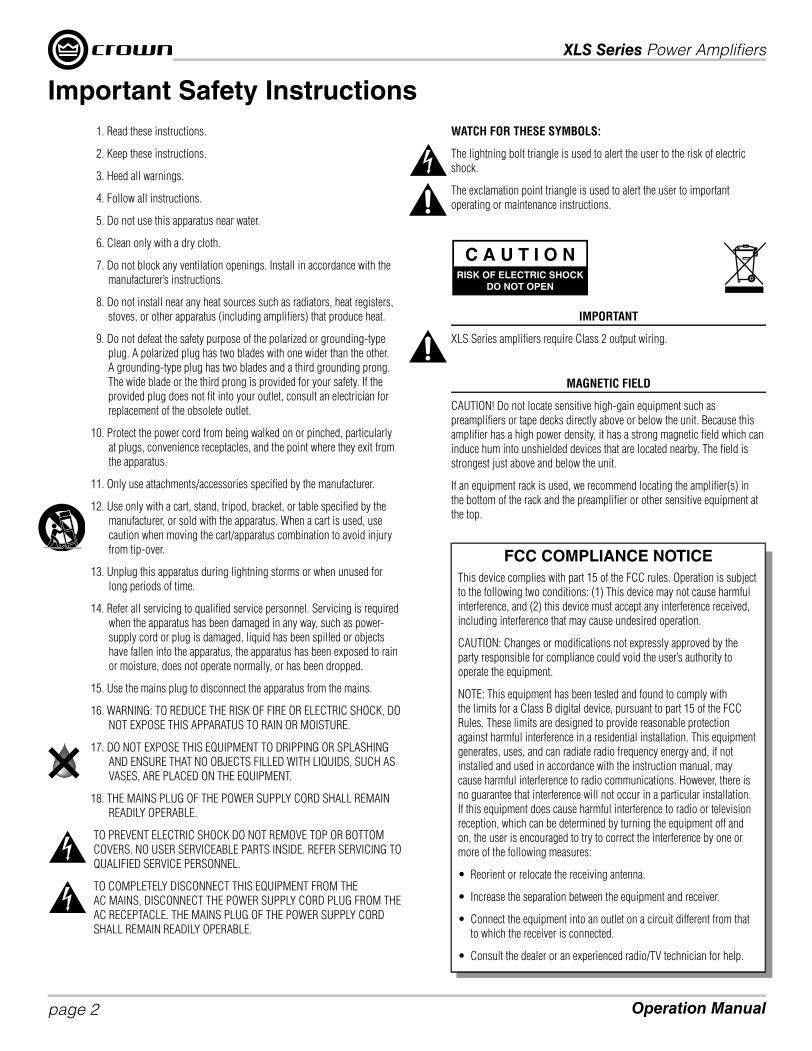
WATCH FOR THESE SYMBOLS:
The lightning bolt triangle is used to alert the user to the risk of electric
shock.
The exclamation point triangle is used to alert the user to important
operating or maintenance instructions.
IMPORTANT
XLS Series amplifi ers require Class 2 output wiring.
MAGNETIC FIELD
CAUTION! Do not locate sensitive high-gain equipment such as
preamplifi ers or tape decks directly above or below the unit. Because this
amplifi er has a high power density, it has a strong magnetic fi eld which can
induce hum into unshielded devices that are located nearby. The fi eld is
strongest just above and below the unit.
If an equipment rack is used, we recommend locating the amplifi er(s) in
the bottom of the rack and the preamplifi er or other sensitive equipment at
the top.
Important Safety Instructions
FCC COMPLIANCE NOTICE
This device complies with part 15 of the FCC rules. Operation is subject
to the following two conditions: (1) This device may not cause harmful
interference, and (2) this device must accept any interference received,
including interference that may cause undesired operation.
CAUTION: Changes or modifi cations not expressly approved by the
party responsible for compliance could void the user’s authority to
operate the equipment.
NOTE: This equipment has been tested and found to comply with
the limits for a Class B digital device, pursuant to part 15 of the FCC
Rules. These limits are designed to provide reasonable protection
against harmful interference in a residential installation. This equipment
generates, uses, and can radiate radio frequency energy and, if not
installed and used in accordance with the instruction manual, may
cause harmful interference to radio communications. However, there is
no guarantee that interference will not occur in a particular installation.
If this equipment does cause harmful interference to radio or television
reception, which can be determined by turning the equipment off and
on, the user is encouraged to try to correct the interference by one or
more of the following measures:
• Reorient or relocate the receiving antenna.
• Increase the separation between the equipment and receiver.
• Connect the equipment into an outlet on a circuit different from that
to which the receiver is connected.
• Consult the dealer or an experienced radio/TV technician for help.

XLS Series Power Amplifi ers
page 3Operation Manual
DECLARATION OF CONFORMITY
Issued By: Harman International.
1718 W. Mishawaka Rd.
Elkhart, IN 46517 U.S.A.
FOR COMPLIANCE QUESTIONS ONLY: Sue Whitfi eld
574-294-8289
Sue.Whitfi [email protected]
European Representative’s Name and Address:
David J. Budge
10 Harvest Close
Yateley
GU46 6YS
United Kingdom
Equipment Type: Power amplifi ers
Family Name: XLS Series
Model Names: XLS 1000, XLS 1500, XLS 2000, XLS 2500
EMC Standards:
EN 55103-1:1997 Electromagnetic Compatibility – Product Family Standard for Audio, Video, Audio-Visual and Entertainment Lighting Control Apparatus for
Professional Use, Part 1: Emissions
EN 55103-1:1997 Magnetic Field Emissions-Annex A @ 10 cm and 1 M
EN 61000-3-2:2005 & Amd 1: 2008 Limits for Harmonic Current Emissions (equipment input current ≤16A per phase)
EN 61000-3-3:1998 Limitation of Voltage Fluctuations and Flicker in Low-Voltage Supply Systems Rated Current ≤16A
EN 55022:2006 Limits and Methods of Measurement of Radio Disturbance Characteristics of ITE: Radiated, Class B Limits; Conducted, Class B
EN 55103-2:1997 Electromagnetic Compatibility – Product Family Standard for Audio, Video, Audio-Visual and Entertainment Lighting Control Apparatus for
Professional Use, Part 2: Immunity
EN 61000-4-2:2001 Electrostatic Discharge Immunity (Environment E2-Criteria B, 4k V Contact, 8k V Air Discharge)
EN 61000-4-3:2006 Radiated, Radio-Frequency, Electromagnetic Immunity (Environment E2, Criteria A)
EN 61000-4-4:2007 Electrical Fast Transient/Burst Immunity (Criteria B)
EN 61000-4-5:2006 Surge Immunity (Criteria B)
EN 61000-4-6:2006 Immunity to Conducted Disturbances Induced by Radio-Frequency Fields (Criteria A)
EN 61000-4-11:2001 Voltage Dips, Short Interruptions and Voltage Variation
Safety Standard:
IEC 60065: 2001: 7Ed & Amd 1: 2005 Safety Requirements - Audio Video and Similar Electronic Apparatus
I certify that the product identifi ed above conforms to the requirements of the EMC Council Directive 89/336/EEC as amended by 92/31/EEC,
and the Low Voltage Directive 73/23/EES as amended by 93/68/EEC.
Signed ______________________
Andrew Stump
Title: Director of Manufacturing Date of Issue: February 1, 2010

XLS Series Power Amplifi ers
Operation Manualpage 4
Stereo Bypass Mode
This is the default mode the amplifi er is set to from the factory. The amplifi er is
confi gured for stereo mode with the PureBand™ Crossover System Bypassed.
1. Connect Left/Right signal source to Channel 1 and Channel 2 using either
the XLR, ¼ Inch, or RCA connectors.
2. Connect a speaker to each channel output using Speakon®, Banana Plugs,
or bare wire.
Bridge-Mono Mode
Bridge-Mono Mode delivers the power of both amp channels into a single 8 or
4 ohm load.
Before you get started ensure that you:
1. Connect signal source to Channel 1 only using either the XLR, ¼ Inch, or
RCA connectors.
2. Connect the speaker as shown.
a. If using the binding post outputs, connect the positive terminal of the
speaker to the positive terminal of Channel 1 and the negative terminal of
the speaker to the positive terminal of Channel 2.
b. If using a Speakon® connector, connect the positive terminal of the speaker to 1+ and the negative terminal to 2+.
Plug the connector into the Channel 1 output only.
Follow these quick steps to confi gure the amplifi er for “Bridge Mode”:
1. Hold the “Mode/Menu” button down for 3 sec until the LCD screen displays “Amp Mode <More>”.
2. Press the “Mode/Menu” button to begin confi guring the Amp Mode.
3. Press the “Next” button until the LCD screen reads “Mode: Bridge”.
4. Press the “Mode/Menu” button to confi rm your selection.
5. Now press the “Next” button until the LCD screen displays “Bypass”. Press the “Mode/Menu” button to confi rm your selection. The LCD screen should now read
“Bridge Bypass”.
Crossover Mode
When using the “Crossover Mode”, the amplifi er is confi gured to use a LowPass
Filter on Channel 1 and a HighPass Filter on Channel 2.
Before you get started ensure that you:
1. Connect signal source to Channel 1 only using either the XLR, ¼ Inch, or
RCA connectors.
2. Connect a speaker to each channel output using Speakon®, Banana Plugs,
or bare wire.
Follow these quick steps to confi gure the amplifi er for “Crossover Mode”:
1. Hold the “Mode/Menu” button down for 3 sec until the LCD screen displays
“Amp Mode <More>”.
2. Press the “Mode/Menu” button to begin confi guring the Amp Mode.
3. Press the “Next” button until the LCD screen displays “Input Y”. Now press the “Mode/Menu” button to confi rm.
4. Now press the “Next” button until the LCD screen displays “XOVER” and press the “Mode/Menu” button to confi rm.
5. Now use the “Previous” or “Next” button to select your desired crossover point.
6. Once you have selected your crossover point, press the “Mode/Menu” button to confi rm your selection. The LCD screen should now read “Input Y XOVER”.
Get Started

XLS Series Power Amplifi ers
page 5Operation Manual
LowPass Mode
When using the “LowPass Mode”, the amplifi er is confi gured to use a LowPass
Filter on Channel 1 and Channel 2 at the selected frequency.
Before you get started ensure that you:
1. Connect Left/Right signal source to Channel 1 and Channel 2 using
either the XLR, ¼ Inch, or RCA connectors.
2. Connect a speaker to each channel output using Speakon®, Banana
Plugs, or bare wire.
Follow these quick steps to confi gure the amplifi er for “HighPass Mode”:
1. Hold the “Mode/Menu” button down for 3 sec until the LCD screen
displays “Amp Mode <More>”.
2. Press the “Mode/Menu” button to begin confi guring the Amp Mode.
3. Press the “Next” button until the LCD screen displays “Stereo”. Now press the “Mode/Menu” button to confi rm.
4. Now press the “Next” button until the LCD screen displays “LowPass” and press the “Mode/Menu” button to confi rm.
5. Now use the “Previous” or “Next” button to select your desired crossover point.
6. Once you have selected your crossover point, press the “Mode/Menu” button to confi rm your selection. The LCD screen should now read “Stereo LowPass”.
HighPass Mode
When using the “HighPass Mode”, the amplifi er is confi gured to use a HighPass
Filter on Channel 1 and Channel 2 at the selected frequency.
Before you get started ensure that you:
1. Connect Left/Right signal source to Channel 1 and Channel 2 using either
the XLR, ¼ Inch, or RCA connectors.
2. Connect a speaker to each channel output using Speakon®, Banana Plugs,
or bare wire.
Follow these quick steps to confi gure the amplifi er for “HighPass Mode”:
1. Hold the “Mode/Menu” button down for 3 sec until the LCD screen
displays “Amp Mode <More>”.
2. Press the “Mode/Menu” button to begin confi guring the Amp Mode.
3. Press the “Next” button until the LCD screen displays “Stereo”. Now press the “Mode/Menu” button to confi rm.
4. Now press the “Next” button until the LCD screen displays “HighPass” and press the “Mode/Menu” button to confi rm.
5. Now use the “Previous” or “Next” button to select your desired crossover point.
6. Once you have selected your crossover point, press the “Mode/Menu” button to confi rm your selection. The LCD screen should now read “Stereo HighPass”.
Get Started

XLS Series Power Amplifi ers
Operation Manualpage 6
Crown’s XLS Series amplifi ers defi ne the standard for portable PA systems with unmatched performance, technology and
affordability that effortlessly deliver the goods night after night. We packed XLS with enormous fl exibility, thanks to its
integrated Crossover and PeakX
™ Limiters. The XLS weighs under 11 pounds, compared to 40 pounds for its competitors.
Simply put, the XLS is the most powerful, fl exible, effi cient amp available in its class.
Modern power amplifi ers are sophisticated pieces of engineering capable of producing extremely high power levels. They
must be treated with respect and correctly installed if they are to provide the many years of reliable service for which they
were designed.
In addition, XLS Series amplifi ers include a number of features which require some explanation before they can be used to
their maximum advantage.
Please take the time to study this manual so that you can obtain the best possible service from your amplifi er.
Features
• High performance, lightweight Class-D amplifi er powered by DriveCore™ Technology
• Integrated PureBand™ Crossover System ensures seamless transitions from low to high frequency drivers
• Integrated PeakX™ Limiters provide maximum output while protecting your speakers
• XLR, ¼", RCA inputs ensure compatibility with any source
• ¼" Inputs can be used as loop-thrus to distribute signal to additional amplifi ers
• Crown No-Fault Fully-Transferable 3-year Warranty completely protects your investment
How to Use This Manual
This manual provides you with the necessary information to safely and correctly setup and operate your amplifi er. It does
not cover every aspect of installation, setup or operation that might occur under every condition. For additional information,
please consult Crown’s Amplifi er Application Guide (available online at www.crownaudio.com), Crown Technical Support, your
system installer or retailer.
We strongly recommend you read all instructions, warnings and cautions contained in this manual. Also, for your protection,
please send in your warranty registration card today. And save your bill of sale — it’s your offi cial proof of purchase.
Welcome

XLS Series Power Amplifi ers
page 7Operation Manual
Indicators:Signal Presence Indicator: Two green LED’s, one for each channel, illuminate when the channel input signal exceeds -40dBu
-10 Indicator: Green LED flashes when output signal level exceeds -10dB below clip
-20 Indicator: Green LED flashes when output signal level exceeds -20dB below clip
Clip Indicator: Two red LED’s, one for each channel, illuminate when the channel’s output is being overdriven.
Thermal Indicator: Two red LED’s, one for each channel, illuminate when thermal compression begins.
Cooling Vents:Front to rear forced air flow.
Gain (Level) Controls:Two black rotary level controls, one for each channel.
Menu/Prev/Next:Three buttons located near the LCD screen that are used to configure and access the integrated processing.
Power ButtonTurns amplifier power on and off. Blue LED will illuminate when power is turned on.
LCD Screen:Back-lit LCD screen allows for crossover configuration, amplifier mode configuration, and limiter configuration.
Binding Post Output Jacks: One pair per channel, accepts banana plugs or bare wire. Note: Binding post outputs on European models come with safety plugs installed to prevent European power plugs from being inserted. The side entry positions for these connectors should be used with European models.
Fans: Provide front to back forced airflow for cooling.
AC Power
Connector
4-Pole Speakon® Output Connectors:These two connectors accept 2-pole or 4-pole Speakon connectors. The channel 1 connector is wired for both channels so it can be used for bridge-mode wiring or stereo wiring of two speakers to a single Speakon.
¼ Inch Inputs:2 – ¼ Inch input connectors are provided (one per channel). These inputs can also be used to loop-thru signal to additional amplifiers.
Circuit Breaker: Provides overload protection
RCA (Phono) Inputs: Two RCA inputs are provided (one per channel)
Balanced XLR Inputs:Two 3-pin XLR input connectors are provided (one per channel)
Front Panel Features
Back Panel Features

XLS Series Power Amplifi ers
Operation Manualpage 8
PureBand™ Crossover System:
The PureBand™ Crossover System provides a variable state Linkwitz-Riley 24dB/octave fi lter allowing you to choose a point
between 50Hz and 3kHz on 1/12th octave centers. The following points are available for choice:
50Hz, 53Hz, 56Hz, 59Hz, 63Hz, 66Hz, 70Hz, 74Hz, 79Hz, 83Hz, 88Hz, 94Hz, 99Hz, 105Hz, 111Hz, 118Hz, 125Hz,
132Hz, 140Hz, 149Hz, 157Hz, 167Hz, 177Hz, 187Hz, 198Hz, 210Hz, 223Hz, 236Hz, 250Hz, 265Hz, 281Hz, 297Hz,
315Hz, 334Hz, 354Hz, 375Hz, 397Hz, 420Hz, 472Hz, 500Hz, 530Hz, 561Hz, 595Hz, 630Hz, 667Hz, 707Hz, 749Hz,
794Hz, 841Hz, 891Hz, 944Hz, 1.00kHz, 1.06kHz, 1.12kHz, 1.19kHz, 1.26kHz, 1.33kHz, 1.41kHz, 1.50kHz, 1.59kHz,
1.68kHz, 1.78kHz, 1.89kHz, 2.00kHz, 2.12kHz, 2.24kHz, 2.38kHz, 2.52kHz, 2.67kHz, 2.83kHz, 3.00kHz
Along with your choice in crossover frequency, the PureBand™ Crossover System also provides you with four modes to
choose from:
Crossover Mode (CH1=LPF, CH2=HPF): When selected, this mode enables a LowPass Filter on Channel 1 and a
HighPass Filter on Channel 2 at the frequency that you have chosen.
Note: This mode will automatically put the input mode into “Input Y”.
LowPass Mode (CH1=LPF, CH2 = LPF): When selected, this mode enables a LowPass Filter on both Channel 1
and Channel 2 at the frequency that you have chosen.
HighPass Mode (CH1 = HPF, CH2 = HPF): When selected, this mode enables a HighPass Filter on both Channel 1
and Channel 2 at the frequency that you have chosen.
Bridge Mode (either LPF or HPF): When bridge-mono mode is selected, the crossover system still allows you to
select a LowPass or HighPass fi lter at the frequency that you have chosen.
For instructions on setting up the different crossover system settings, please see the “Get Started” section at the beginning
of this manual.
PeakX™ Limiters
The PeakX Clip Limiters provide your amplifi er and system with higher performance and better protection. They are specifi cally
tuned to work with this amplifi er design and power-supply to achieve higher SPL with less audible artifacts while protecting
your loudspeaker investment. The limiters can easily be turned on or off from the front panel.
Note: The PeakX Limiters are shipped in the “On” confi guration from the factory.
Instructions for Engaging/Disengaging the PeakX™ Limiters:
1. Hold the “Mode/Menu” button down for 3 sec until the LCD screen displays “Amp Mode <More>”
2. Press the “Next” button – The LCD screen displays “CH1 Clip <More>”.
3. Press the “Mode/Menu” button and use the “Next” button to toggle between on/off.
4. Once you have made your selection, press the “Mode/Menu” button to confi rm. When you confi rm CH1 Clip
confi guration, you are automatically taken to Ch2 Clip to confi gure either on or off. Once again, make your selection and
press “Mode/Menu” to confi rm.
Integrated Processing Features

Weitere Sprachversionen: Um Informationen über die Nutzung dieses Produktes in anderen Sprachen zu erhalten, wenden Sie sich bitte an Ihren örtlichen Crown-
Händler. Wenn Sie Hilfe dabei benötigen, Ihren örtlichen Händler ausfi ndig zu machen, kontaktieren Sie Crown bitte unter 574-294-8000.
Dieses Handbuch enthält nicht alle Einzelheiten zu Design, Herstellung oder Varianten des Gerätes. Es deckt auch nicht jeden möglichen Fall ab, der während Installation,
Betrieb oder Wartung auftreten könnte.
Die in diesem Handbuch enthaltenen Informationen waren bei Erscheinungsdatum zutreffend. Es können jedoch Aktualisierungen zu diesen Informationen vorliegen. Um die
neueste Version dieses Handbuchs zu erhalten, besuchen Sie bitte die Crown-Webseite auf www.crownaudio.com.
Rechtlicher Hinweis: Crown, Crown Audio und Amcron sind eingetragene Handelsmarken von Crown International. Sonstige Handelsmarken sind das Eigentum ihrer
jeweiligen Eigentümer. Spätere Versionen dieses Handbuchs und zusätzliche Informationen zu diesem Produkt stehen gegebenenfalls auf der Crown-Webseite auf
www.crownaudio.com zur Verfügung.
Einige Modelle können unter dem Namen Amcron® exportiert werden.
©2010 by Crown Audio®, Inc., 1718 W. Mishawaka Rd., Elkhart, Indiana 46517-9439 USA, Telefon: 574-294-8000.
XLS 1000
XLS 2000
XLS 1500
XLS 2500
XLS Serie Bedienungsanleitung
142169-1 - 3/10
DEU
TS
CH

XLS Series Power Amplifi ers
Operation Manualpage 10
Stereo Bypass-Modus
Dies ist der Standard-Modus, auf den der Verstärker eingestellt ist, wenn er aus
der Fabrikationsstätte kommt. Der Verstärker wird für den Stereo-Modus mit
dem PureBand™ Crossover System Bypass konfi guriert.
1. Verbinden Sie die linke/rechte Signalquelle mithilfe der XLR-, ¼ Zoll- oder
RCA-Anschlüsse mit Kanal 1 und Kanal 2.
2. Verbinden Sie einen Lautsprecher mithilfe von Speakon®-Steckern,
Bananensteckern oder Blankdraht mit jedem Kanalausgang.
Bridge-Mono-Modus
Der Bridge-Mono-Modus wandelt die Leistung beider Kanäle des Verstärkers in
eine einzige 8 oder 4 Ohm Last um.
Bevor Sie den Verstärker benutzen, stellen Sie bitte sicher, dass Sie:
1. die Signalquelle nur mithilfe der XLR-, ¼ Zoll-, oder RCA-Anschlüsse mit
Kanal 1 verbinden.
2. den Lautsprecher wie dargestellt anschließen.
a. Falls Sie die Schraubklemmenausgänge verwenden, verbinden Sie
den Pluspol des Lautsprechers mit dem Pluspol von Kanal 1 und den
Minuspol des Lautsprechers mit dem Pluspol von Kanal 2.
b. Falls Sie einen Speakon®-Anschluss verwenden, verbinden Sie den Pluspol des Lautsprechers mit 1+ und den
Minuspol mit 2+. Stecken Sie die Steckverbindung nur in den Ausgang von Kanal 1.
Folgen Sie diesen kurzen Schritten, um den Verstärker für den "Bridge-Modus" zu konfi gurieren:
1. Halten Sie den “Mode/Menu”-Knopf 3 Sekunden lang gedrückt, bis die LCD-Anzeige “Amp Mode <More>” anzeigt.
2. Drücken Sie den “Mode/Menu”-Knopf, um mit der Konfi gurierung des Verstärkermodus zu beginnen.
3. Drücken Sie den “Next”-Knopf, bis die LCD-Anzeige “Mode: Bridge” anzeigt.
4. Drücken Sie den “Mode/Menu”-Knopf, um Ihre Wahl zu bestätigen.
5. Drücken Sie nun den “Next”-Knopf, bis die LCD-Anzeige “Bypass" anzeigt. Drücken Sie den “Mode/Menu”-Knopf, um Ihre Wahl zu bestätigen. Die LCD-Anzeige sollte
nun “Bridge Bypass” anzeigen.
Crossover-Modus
Bei der Verwendung des "Crossover-Modus" ist der Verstärker so konfi guriert,
dass dieser ein Tiefpassfi lter für Kanal 1 und ein Hochpassfi lter für Kanal 2
verwendet.
Bevor Sie den Verstärker benutzen, stellen Sie bitte sicher, dass Sie:
1. die Signalquelle nur mithilfe der XLR-, ¼ Zoll-, oder RCA-Anschlüsse mit
Kanal 1 verbinden.
2. einen Lautsprecher mithilfe von Speakon®-Steckern, Bananensteckern oder
Blankdraht mit jedem Kanalausgang verbinden.
Folgen Sie diese kurzen Schritten, um den Verstärker für den "Crossover-
Modus" zu konfi gurieren:
1. Halten Sie den “Mode/Menu”-Knopf 3 Sekunden lang gedrückt, bis die
LCD-Anzeige “Amp Mode <More>” anzeigt.
2. Drücken Sie den “Mode/Menu”-Knopf, um mit der Konfi gurierung des Verstärkermodus zu beginnen.
3. Drücken Sie den “Next”-Knopf, bis die LCD-Anzeige “Input Y" anzeigt. Drücken Sie nun den “Mode/Menu”-Knopf zur Bestätigung.
4. Drücken Sie nun den “Next”-Knopf, bis die LCD-Anzeige "XOVER” anzeigt, und drücken Sie den “Mode/Menu”-Knopf zur Bestätigung.
5. Verwenden Sie nun den “Previous”- oder “Next”-Knopf, um Ihren gewünschten Crossover-Punkt auszuwählen.
6. Wenn Sie den Crossover-Punkt gewählt haben, drücken Sie den “Mode/Menu”-Knopf, um Ihre Wahl zu bestätigen. Die LCD-Anzeige sollte nun “Input Y XOVER” anzeigen.
Einrichtung

XLS Series Power Amplifi ers
page 11Operation Manual
Bei der Verwendung des "Tiefpass-Modus" ist der Verstärker so konfi guriert,
dass dieser ein Tiefpass-Filter für Kanal 1 und Kanal 2 auf der ausgewählten
Frequenz verwendet.
Bevor Sie den Verstärker benutzen, stellen Sie bitte sicher, dass Sie:
1. die linke/rechte Signalquelle mithilfe der XLR-, ¼ Zoll- oder RCA-
Anschlüsse mit Kanal 1 und Kanal 2 verbinden.
2. einen Lautsprecher mithilfe von Speakon®-Steckern, Bananensteckern
oder Blankdraht mit jedem Kanalausgang verbinden.
Folgen Sie diesen kurzen Schritten, um den Verstärker für den "Tiefpass-
Modus" zu konfi gurieren:
1. Halten Sie den “Mode/Menu”-Knopf 3 Sekunden lang gedrückt, bis die
LCD-Anzeige “Amp Mode <More>” anzeigt.
2. Drücken Sie den “Mode/Menu”-Knopf, um mit der Konfi gurierung des Verstärkermodus zu beginnen.
3. Drücken Sie den “Next”-Knopf, bis die LCD-Anzeige “Stereo" anzeigt. Drücken Sie nun den “Mode/Menu”-Knopf zur Bestätigung.
4. Drücken Sie nun den “Next”-Knopf, bis die LCD-Anzeige "LowPass” anzeigt, und drücken Sie den “Mode/Menu”-Knopf zur Bestätigung.
5. Verwenden Sie nun den “Previous”- oder “Next”-Knopf, um Ihren gewünschten Crossover-Punkt auszuwählen.
6. Wenn Sie den Crossover-Punkt gewählt haben, drücken Sie den “Mode/Menu”-Knopf, um Ihre Wahl zu bestätigen. Die LCD-Anzeige sollte nun “Stereo LowPass”
anzeigen.
Hochpass-Modus
Bei der Verwendung des "Hochpass-Modus" ist der Verstärker so konfi guriert,
dass dieser ein Hochpass-Filter für Kanal 1 und Kanal 2 auf der ausgewählten
Frequenz verwendet.
Bevor Sie den Verstärker benutzen, stellen Sie bitte sicher, dass Sie:
1. die linke/rechte Signalquelle mithilfe der XLR-, ¼ Zoll- oder RCA-
Anschlüsse mit Kanal 1 und Kanal 2 verbinden.
2. einen Lautsprecher mithilfe von Speakon®-Steckern, Bananensteckern oder
Blankdraht mit jedem Kanalausgang verbinden.
Folgen Sie diesen kurzen Schritten, um den Verstärker für den "Hochpass-
Modus" zu konfi gurieren:
1. Halten Sie den “Mode/Menu”-Knopf 3 Sekunden lang gedrückt, bis die
LCD-Anzeige “Amp Mode <More>” anzeigt.
2. Drücken Sie den “Mode/Menu”-Knopf, um mit der Konfi gurierung des Verstärkermodus zu beginnen.
3. Drücken Sie den “Next”-Knopf, bis die LCD-Anzeige “Stereo" anzeigt. Drücken Sie nun den “Mode/Menu”-Knopf zur Bestätigung.
4. Drücken Sie nun den “Next”-Knopf, bis die LCD-Anzeige "HighPass” anzeigt, und drücken Sie den “Mode/Menu”-Knopf zur Bestätigung.
5. Verwenden Sie nun den “Previous”- oder “Next”-Knopf, um Ihren gewünschten Crossover-Punkt auszuwählen.
6. Wenn Sie den Crossover-Punkt gewählt haben, drücken Sie den “Mode/Menu”-Knopf, um Ihre Wahl zu bestätigen. Die LCD-Anzeige sollte nun “Stereo HighPass” anzeigen.
Tiefpass-Modus
Einrichtung
XLS Series Power Amplifi ers
Operation Manualpage 12
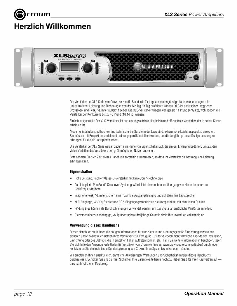
Die Verstärker der XLS Serie von Crown setzen die Standards für tragbare kostengünstige Lautsprecheranlagen mit
unübertroffener Leistung und Technologie, von der Sie Tag für Tag profi tieren können. XLS ist dank seiner integrierten
Crossover- und PeakX
™-Limiter äußerst fl exibel. Die XLS-Verstärker wiegen weniger als 11 Pfund (4,99 kg), wohingegen die
Verstärker der Konkurrenz bis zu 40 Pfund (18,14 kg) wiegen.
Einfach ausgedrückt: Der XLS-Verstärker ist der leistungsstärkste, fl exibelste und effi zienteste Verstärker, der in seiner Klasse
erhältlich ist.
Moderne Endstufen sind hochwertige technische Geräte, die in der Lage sind, extrem hohe Leistungspegel zu erreichen.
Sie müssen mit Respekt behandelt und ordnungsgemäß installiert werden, um die langjährige, zuverlässige Leistung zu
erbringen, für die sie konzipiert wurden.
Die Verstärker der XLS Serie weisen zudem eine Reihe von Eigenschaften auf, die einiger Erklärung bedürfen, um aus den
vielen Vorteilen des Verstärkers den größtmöglichen Nutzen zu ziehen.
Bitte nehmen Sie sich Zeit, dieses Handbuch sorgfältig durchzulesen, so dass Ihr Verstärker die bestmögliche Leistung
erbringen kann.
Eigenschaften
• Hohe Leistung, leichter Klasse-D-Verstärker mit DriveCore™-Technologie
• Das integrierte PureBand™ Crossover-System gewährleistet einen nahtlosen Übergang von Niederfrequenz- zu
Hochfrequenztreibern
• Integrierte PeakX™-Limiter sichern eine maximale Ausgangsleistung und schützen Ihre Lautsprecher.
• XLR-Eingänge, ¼SDSq-Stecker und RCA-Eingänge gewährleisten die Kompatibilität mit sämtlichen Quellen.
• ¼"-Eingänge können als Durchschleifungen verwendet werden, um das Signal an zusätzliche Verstärker zu leiten.
• Die verschuldensunabhängige, völlig übertragbare dreijährige Garantie deckt Ihre Investition vollständig ab.
Verwendung dieses Handbuchs
Dieses Handbuch stellt Ihnen die nötigen Informationen für eine sichere und ordnungsgemäße Einrichtung sowie einen
sicheren und einwandfreien Betrieb Ihres Verstärkers zur Verfügung. Es deckt jedoch nicht sämtliche Aspekte der Installation,
Einrichtung oder des Betriebs, die in einzelnen Fällen auftreten können, ab. Falls Sie weitere Informationen benötigen, lesen
Sie sich bitte den Anwendungsleitfaden für Verstärker von Crown (online auf www.crownaudio.com verfügbar) durch, oder
kontaktieren Sie die technische Kundenbetreuung von Crown, Ihren Systemtechniker oder -händler.
Wir empfehlen Ihnen ausdrücklich, sämtliche Anweisungen, Warnungen und Sicherheitshinweise dieses Handbuchs
durchzulesen. Schicken Sie uns zu Ihrer Sicherheit Ihre Garantiekarte heute noch zu. Heben Sie bitte Ihren Kaufvertrag auf —
dies ist Ihr offi zieller Kaufbeleg.
Herzlich Willkommen

XLS Series Power Amplifi ers
page 13Operation Manual
Anzeigen:Signalanzeige: Zwei grüne LEDs, eine für jeden Kanal, leuchten auf, wenn das Eingangssignal des Kanals -40 dBu überschreitet.
-10-Anzeige: Grüne LED blinkt, wenn das Ausgangssignal -10 dB unter Clip überschreitet.
-20-Anzeige: Grüne LED blinkt, wenn das Ausgangssignal -20 dB unter Clip überschreitet.
Clip-Anzeige: Zwei rote LEDs, eine für jeden Kanal, leuchten auf, wenn das Ausgangssignal des Kanals übersteuert wird.
Wärmeanzeige: Zwei rote LEDs, eine für jeden Kanal, leuchten auf, wenn die thermische Kompression einsetzt.
Lüftungsöffnungen
für Kühlung:Zwangsbelüftung von vorne nach hinten.
Verstärkungs (Pegel)-Steller:Zwei schwarze drehbare Pegelsteller, einer für jeden Kanal.
Menu/Prev/Next:Drei Knöpfe in der Nähe der LCD-Anzeige, die verwendet werden, um die integrierte Verarbeitung zu konfigurieren
An-/Aus-Schalter:Schaltet Stromzufuhr des Verstärkers an und aus. Blaue LED leuchtet auf, wenn der Verstärker eingeschaltet ist.
LCD-Anzeige:Die hinterleuchtete LCD-Anzeige ermöglicht die Crossover-Konfiguration, die Konfiguration des Verstärker-modus und des Limiters.
Buchsen der Schraubklemmenausgänge:Ein Paar pro Kanal, kompatibel mit Bananensteckern oder Blankdraht. Anmerkung: Schraubklemmenaus-gänge bei europäischen Modellen sind mit Schukosteckern versehen, um zu verhindern, dass europäische Netzstecker angeschlossen werden. An den Anschlüssen an der Seite sollten europäische Modelle angeschlossen werden.
Lüfter:Zwangsbelüftung von vorne nach hinten.
AC-
Netzanschluss
4-polige Speakon® -Ausgänge:Diese beiden Anschlüsse sind mit 2-poligen oder 4-poligen Speakon-Anschlüssen kompatibel. Der Anschluss für Kanal 1 ist für beide Kanäle verkabelt, so dass er für eine Bridge-Mono-Verkabelung oder eine Stereo-Verkabelung von zwei Lautsprechern mit einem einzigen Speakon-Anschluss verwendet werden kann.
¼ Zoll-Anschlüsse:2 ¼ Zoll-Anschlüsse sind vorhanden (einer pro Kanal). Diese Eingänge können ebenfalls als Durchschleifungen verwendet werden, um das Signal an zusätzliche Verstärker zu leiten.
Leistungsschalter: Bietet Überlastschutz.
RCA (Phono)-Eingänge: Es sind zwei RCA-Eingänge vorhanden (einer pro Kanal).
Symmetrische
XLR-Eingänge: Zwei 3-Pin XLR-Eingänge sind vorhanden (einer pro Kanal).
Funktionen der Frontplatte
Funktionen der Rückplatte

XLS Series Power Amplifi ers
Operation Manualpage 14
PureBand™ Crossover-System:
Das PureBand™ Crossover-System besitzt ein zustandsvariables Linkwitz-Riley-Filter (24dB/Oktave) für 1/12
Oktavmittenfrequenzen, das Ihnen ermöglicht, einen Crossover-Punkt zwischen 50Hz und 3kHz auszuwählen. Die folgenden
Crossover-Punkte stehen zur Auswahl:
50Hz, 53Hz, 56Hz, 59Hz, 63Hz, 66Hz, 70Hz, 74Hz, 79Hz, 83Hz, 88Hz, 94Hz, 99Hz, 105Hz, 111Hz, 118Hz, 125Hz,
132Hz, 140Hz, 149Hz, 157Hz, 167Hz, 177Hz, 187Hz, 198Hz, 210Hz, 223Hz, 236Hz, 250Hz, 265Hz, 281Hz, 297Hz,
315Hz, 334Hz, 354Hz, 375Hz, 397Hz, 420Hz, 472Hz, 500Hz, 530Hz, 561Hz, 595Hz, 630Hz, 667Hz, 707Hz, 749Hz,
794Hz, 841Hz, 891Hz, 944Hz, 1,00kHz, 1,06kHz, 1,12kHz, 1,19kHz, 1,26kHz, 1,33kHz, 1,41kHz, 1,50kHz, 1,59kHz,
1,68kHz, 1,78kHz, 1,89kHz, 2,00kHz, 2,12kHz, 2,24kHz, 2,38kHz, 2,52kHz, 2,67kHz, 2,83kHz, 3,00kHz
Zusätzlich zur Auswahlmöglichkeit der Crossover-Frequenz, bietet das PureBand™ Crossover-System vier
Auswahlmöglichkeiten bezüglich der Modi:
Crossover-Modus (CH1=LPF, CH2=HPF): Dieser Modus aktiviert ein Tiefpassfi lter für Kanal 1 und ein
Hochpassfi lter für Kanal 2 auf der von Ihnen ausgewählten Frequenz.
Hinweis: Durch diesen Modus wird der Eingangsmodus automatisch auf "Input Y" umgestellt.
Tiefpass-Modus (CH1=LPF, CH2 = LPF): Dieser Modus aktiviert ein Tiefpassfi lter sowohl für Kanal 1 als auch für
Kanal 2 auf der von Ihnen ausgewählten Frequenz.
Hochpass-Modus (CH1 = HPF, CH2 = HPF): Dieser Modus aktiviert ein Hochpassfi lter sowohl für Kanal 1 als auch
für Kanal 2 auf der von Ihnen ausgewählten Frequenz.
Bridge-Modus (entweder LPF oder HPF): Wenn der Bridge-Modus ausgewählt ist, können Sie über das Crossover-
System immer noch einen Tiefpass- oder Hochpassfi lter auf der von Ihnen ausgewählten Frequenz auswählen.
Falls Sie Anweisungen zur Einrichtung der verschiedenen Einstellungen des Crossover-Systems benötigen, lesen Sie sich bitte
den Abschnitt "Einrichtung" am Anfang dieses Handbuchs durch.
PeakX™-Limiter
Durch die PeakX-Clip-Limiter erreichen Ihr Verstärker sowie das System eine höhere Leistung und werden besser geschützt.
Diese sind speziell auf dieses Verstärkermodell und dessen Netzspannung abgestimmt, um höhere Schalldruckpegel mit
weniger akustischen Artefakten zu erzielen und Ihren Lautsprecher zu schützen. Die Limiter können ganz leicht über die
Frontplatte ein- und ausgeschaltet werden.
Hinweis: Die Fabrikationsstätte liefert die PeakX-Limiter in der "On"-Konfi guration.
Anweisungen für die Aktivierung/Deaktivierung der PeakX™-Limiter:
1. Halten Sie den “Mode/Menu”-Knopf 3 Sekunden lang gedrückt, bis die LCD-Anzeige “Amp Mode <More>” anzeigt.
2. Drücken Sie den “Next”-Knopf – die LCD-Anzeige zeigt “CH1 Clip <More>” an.
3. Drücken Sie den “Mode/Menu”-Knopf, und verwenden Sie den "Next"-Knopf, um zwischen ein/aus hin- und herzuschalten.
4. Wenn Sie Ihre Auswahl getroffen haben, drücken Sie den “Mode/Menu”-Knopf zur Bestätigung. Wenn Sie die Clip-
Konfi guration für Kanal 1 bestätigen, werden Sie automatisch zu dem Kanal 2-Clip geleitet, um entweder "ein" oder "aus"
auszuwählen. Treffen Sie wiederum Ihre Auswahl, und drücken Sie "Mode/Menu" zur Bestätigung.
Integrierte Verarbeitungsfunktionen

Obtención de Versiones en otro Idioma: para obtener información en otro idioma sobre el uso de este producto, por favor póngase en contacto con su Distribuidor
local de Crown. Si necesita ayuda para ubicar a un distribuidor local, por favor póngase en contacto con Crown al 574-294-8000.
Este manual no incluye todos los detalles del diseño, fabricación o variaciones del equipo. Así como tampoco incluye todas las posibles situaciones que pueden surgir en el
momento de la instalación, operación o mantenimiento.
Este manual posee información que en el momento de la publicación se consideró certera. No obstante, esta información puede haberse actualizado. Para conseguir la
última versión de este manual, por favor visite la página Web de Crown www.crownaudio.com.
Aviso de Marca Registrada: Crown, Crown Audio y Amcron son marcas registradas de Crown International. Las otras marcas son propiedad de sus respectivos dueños.
Las versiones posteriores de este manual e información adicional sobre este producto pueden estar disponibles en la página Web de Crown www.crownaudio.com.
Algunos modelos pueden ser exportados bajo el nombre Amcron®
©2010 por Crown Audio®, S.A., 1718 W. Mishawaka Rd., Elkhart, Indiana 46517-9439 EE.UU. Teléfono: 574-294-8000.
XLS 1000
XLS 2000
XLS 1500
XLS 2500
Serie XLS Manual de Operación
142169-1 - 3/10
ES
PA
ÑO
L

XLS Series Power Amplifi ers
Operation Manualpage 16
Modo Estéreo Bypass
Este es el modo que viene en el amplifi cador por defecto de fábrica. El amplifi cador
está confi gurado para modo estéreo con el PureBand™ Crossover System
Bypassed.
1. Conectar la fuente de señal Izquierda/Derecha con el canal 1 y con el canal 2
utilizando cualquiera de los conectores XLR, ¼ Pulgada, o RCA.
2. Conectar un altavoz a cada canal de salida utilizando un conector Speakon®,
Enchufes Banana, o cable pelado.
Modo Mono-Puente
El Modo Mono-Puente emite la potencia de ambos canales del amplifi cador a una
sola carga de 8 o 4 ohmios.
Antes de comenzar asegurarse de:
1. Conectar la fuente de señal al Canal 1 sólo utilizando cualquiera de los
conectores XLR, ¼ Pulgada, o RCA .
2. Conectar el altavoz como se muestra.
a. Si se utiliza las salidas de posición vinculante, conectar la terminal positiva
del altavoz con la terminal positiva del Canal 1 y la terminal negativa del
altavoz con la terminal positiva del Canal 2.
b. Si se utiliza un conector Speakon® ,conectar la terminal positiva del altavoz con el 1+ y la terminal negativa con el 2+.
Enchufar el conector en la salida del Canal 1 solo.
Seguir estos sencillos pasos para confi gurar el amplifi cador en "Modo Puente":
1. Mantener presionado el botón "Modo/Menú" por 3 segundos hasta que en la pantalla LCD aparezca "Modo Amp <Más>".
2. Presionar el botón "Modo/Menú" para comenzar la confi guración del Modo Amplifi cador.
3. Presionar el botón "Siguiente" hasta que en la pantalla LCD se lea "Modo: Puente".
4. Presionar el botón "Modo/Menú" para confi rmar la selección.
5. Presionar el botón "Siguiente" hasta que en la pantalla LCD aparezca "Bypass". Presionar el botón "Modo/Menú" para confi rmar la selección. Ahora en la pantalla LCD debería
aparecer "Bypass Puente".
Modo Crossover
Cuando se utiliza el "Modo Crossover", el amplifi cador está confi gurado para usar
un Filtro Lowpass en el Canal 1 y un Filtro HighPass en el Canal 2.
Antes de comenzar asegurarse de:
1. Conectar la fuente de señal al Canal 1 sólo utilizando cualquiera de los
conectores XLR, ¼ Pulgada, o RCA .
2. Conectar un altavoz a cada canal de salida utilizando un conector Speakon®,
Enchufes Banana, o cable pelado.
Seguir estos sencillos pasos para confi gurar el amplifi cador en "Modo Crossover":
1. Mantener presionado el botón "Modo/Menú" por 3 segundos hasta que en la
pantalla LCD aparezca "Modo Amp <Más>".
2. Presionar el botón "Modo/Menú" para comenzar la confi guración del Modo
Amplifi cador.
3. Presionar el botón "Siguiente" hasta que en la pantalla LCD aparezca "Entrada Y". Ahora presionar el botón "Modo/Menú para confi rmar.
4. Ahora presionar el botón "Siguiente" hasta que en la pantalla LCD aparezca "XOVER" y presionar el botón "Modo/Menú" para confi rmar.
5. Ahora utilizar el botón "Anterior" o "Siguiente" para seleccionar el punto crossover deseado.
6. Una vez que se seleccionó el punto crossover, presionar el botón "Modo/Menú" para confi rmar la selección. Ahora en la panatalla LCD debería decir "Entrada Y XOVER".
Comenzar

XLS Series Power Amplifi ers
page 17Operation Manual
Modo LowPass
Cuando se utiliza el "Modo LowPass", el amplifi cador está confi gurado para usar
un Filtro LowPass en el Canal 1 y en el Canal 2 en la frecuencia seleccionada.
Antes de comenzar asegurarse de:
1. Conectar la fuente de señal Izquierda/Derecha con el canal 1 y con el canal 2
utilizando cualquiera de los conectores XLR, ¼ Pulgada, o RCA.
2. Conectar un altavoz a cada canal de salida utilizando un conector Speakon®,
Enchufes Banana, o cable pelado.
Seguir estos sencillos pasos para confi gurar el amplifi cador en "Modo HighPass":
1. Mantener presionado el botón "Modo/Menú" por 3 segundos hasta que en
la pantalla LCD aparezca "Modo Amp <Más>".
2. Presionar el botón "Modo/Menú" para comenzar la confi guración del Modo
Amplifi cador.
3. Presionar el botón "Siguiente" hasta que en la pantalla LCD aparezca "Estéreo". Ahora presionar el botón "Modo/Menú para confi rmar.
4. Ahora presionar el botón "Siguiente" hasta que en la pantalla LCD aparezca "LowPass" y presionar el botón "Modo/Menú" para confi rmar.
5. Ahora utilizar el botón "Anterior" o "Siguiente" para seleccionar el punto crossover deseado.
6. Una vez que se seleccionó el punto crossover, presionar el botón "Modo/Menú" para confi rmar la selección. Ahora en la pantalla LCD debería aparecer "LowPass Estéreo".
Modo HighPass
Cuando se utiliza el "Modo HighPass", el amplifi cador está confi gurado para usar
un Filtro HighPass en el Canal 1 y en el Canal 2 en la frecuencia seleccionada.
Antes de comenzar asegurarse de:
1. Conectar la fuente de señal Izquierda/Derecha con el canal 1 y con el canal 2
utilizando cualquiera de los conectores XLR, ¼ Pulgada, o RCA.
2. Conectar un altavoz a cada canal de salida utilizando un conector Speakon®,
Enchufes Banana, o cable pelado.
Seguir estos sencillos pasos para confi gurar el amplifi cador en "Modo HighPass":
1. Mantener presionado el botón "Modo/Menú" por 3 segundos hasta que en la
pantalla LCD aparezca "Modo Amp <Más>".
2. Presionar el botón "Modo/Menú" para comenzar la confi guración del Modo
Amplifi cador.
3. Presionar el botón "Siguiente" hasta que en la pantalla LCD aparezca "Estéreo". Ahora presionar el botón "Modo/Menú
para confi rmar.
4. Ahora presionar el botón "Siguiente" hasta que en la pantalla LCD aparezca "HighPass" y presionar el botón "Modo/Menú" para confi rmar.
5. Ahora utilizar el botón "Anterior" o "Siguiente" para seleccionar el punto crossover deseado.
6. Una vez que se seleccionó el punto crossover, presionar el botón "Modo/Menú" para confi rmar la selección. En la pantalla LCD ahora debería aparecer "HighPass Estéreo".
Comenzar

XLS Series Power Amplifi ers
Operation Manualpage 18
Los amplifi cadores Crown Serie XLS defi nen un modelo para sistemas portátiles PA con tecnología, viabilidad y
funcionamiento incomparables que sin esfuerzo entregan el producto noche tras noche. Empacamos los XLS con mucha
fl exibilidad, gracias a su Crossover integrado yX
™ Limitadores Peak. El XLS pesa menos de 11 libras (4,99 kg.), comparado
con sus competidores que pesan 40 libras (18,14 kg.).
Simplemente, el XLS es el amplifi cador más potente, fl exible y efi ciente de su clase.
Los amplifi cadores de potencia modernos son piezas sofi sticadas de ingeniería capaz de
producir niveles de potencia extremadamente altos. Se los debe tratar con respeto e instalarlos
correctamente si han sido diseñados para ofrecer varios años de servicio confi able. Además,
los amplifi cadores Serie XLS incluyen un número de características que requieren explicación
antes de poder utilizar sus máximas ventajas.Por favor tomarse el tiempo necesario para
estudiar este manual para poder obtener el mejor servicio posible del amplifi cador.
Características
• Alto rendimiento, ligero amplifi cador Clase-D impulsado por DriveCore™ Tecnología
• Sistema Crossover integrado PureBand ™ que asegura la transición sin fi suras de baja frecuencia a conductores de alta
frecuencia
• Los limitadores integrados Peak X™proporcionan máxima salida y a la vez protegen los altavoces.
• XLR, ¼SDSq, RCA entradas que aseguran la compatibilidad con cualquier fuente
• ¼" Las entradas pueden ser utilizadas como "loop-thrus" para distribuir señal a otros amplifi cadores
• La garantía total Crown de 3 años enteramente transferible protege la inversión por completo.
Cómo Utilizar este Manual
Este manual le brinda la información necesaria para una instalación y funcionamiento corrrectos y seguros del amplifi cador.
No cubre todos los aspectos de instalación, puesta en marcha o funcionamiento que pudieran ocurrir bajo cualquier
condición. Para mayor información, ponerse en contacto con el Guía de Aplicación de Amplifi cadores de Crown (disponible
en línea en la página Web www.crownaudio.com), Apoyo Técnico de Crown, el instalador de sistema o vendedor minorista.
Recomendamos leer todas las instrucciones, advertencias y precauciones que posee este manual. Además, por seguridad, por
favor enviar hoy la carta de certifi cación de garantía. Y conservar la factura de venta – es el comprobante ofi cial de la compra.
Bienvenido

XLS Series Power Amplifi ers
page 19Operation Manual
Indicadores:Indicador de presencia de señal: Dos LEDs verdes, uno para cada canal, se iluminan cuando la señal del canal de entrada
-10 Indicador: El LED verde parpadea cuando la señal de salida excede -10dB por debajo del clip
-20 Indicador: El LED verde parpadea cuando la señal de salida excede -20dB por debajo del clip.
Indicador Clip: Dos LEDs rojos, uno para cada canal, se iluminan cuando la salida del canal está saturada.
Indicador Termal: Dos LEDs rojos, uno para cada canal, se iluminan cuando comienza la compresión termal.
Rejillas de Ventilación:Flujo de aire forzado de adelante hacia atrás.
Controles (nivel):Dos controles de nivel giratorios negros, uno para cada canal.
Menú/Anterior/SiguienteTres botones ubicados cerca dela pantalla LCD que se utilizan para configurar y acceder al proceso integrado.
Botón de EncendidoEnciende y apaga el amplificador. El LED azul se iluminará cuando está encendido.
La pantalla LCD:La iluminación desde atrás de la pantalla permite la configuración crossover, la configuración del modo amplificador, y la configuración del limitador.
Tomas de salida con posición vinculante:Uno por canal, acepta enchufes banana o cable pelado. Nota: las salidas con posición vinculante en los odelos europeos vienen con enchufes de seguridad instalados para prevenir que se coloquen enchufes de energía europea. Las posiciones de entrada para estos conectores deberían usarse con modelos europeos.
Ventiladores:Porporcionan aire forzado de adelante hacia atrás por refrigeración.
Energía CA
Conector
Conectores de salida 4-Pole Speakon®:Estos dos conectores aceptan conectores Speakon de 2-polo o 4-polo El conector del canal 1 está conectado para ambos canales entonces puede usarse para cableado modo-puente o cableado estéreo de dos altavoces a un solo Speakon.
Entradas ¼ Pulgada:se proporcionan conectores de entrada de 2 - ¼ Pulgada (uno por canal). Estas entradas también pueden ser utilizadas para señal "loop-thru" para otros amplificadores.
Disyuntor: Porporciona protección contra sobrecarga.
Entradas RCA (teléfono):Posee dos entradas RCA (una por canal).
Entradas niveladas XLR:Posee dos conectores de entrada 3-pin XLR (uno por canal)
Funciones del Panel Frontal
Funciones del Panel Trasero

XLS Series Power Amplifi ers
Operation Manualpage 20
Sistema PureBand™ Crossover:
El Sistema PureBand™ Crossover proporciona una variable de estado del fi ltro Linkwitz-Riley 24dB/octava que le permite
seleccionar un punto entre 50Hz y 3kHz sobre centros de octava 1/12th. Los siguientes puntos están disponibles para la selección:
50Hz, 53Hz, 56Hz, 59Hz, 63Hz, 66Hz, 70Hz, 74Hz, 79Hz, 83Hz, 88Hz, 94Hz, 99Hz, 105Hz, 111Hz, 118Hz, 125Hz,
132Hz, 140Hz, 149Hz, 157Hz, 167Hz, 177Hz, 187Hz, 198Hz, 210Hz, 223Hz, 236Hz, 250Hz, 265Hz, 281Hz, 297Hz,
315Hz, 334Hz, 354Hz, 375Hz, 397Hz, 420Hz, 472Hz, 500Hz, 530Hz, 561Hz, 595Hz, 630Hz, 667Hz, 707Hz, 749Hz,
794Hz, 841Hz, 891Hz, 944Hz, 1.00kHz, 1.06kHz, 1.12kHz, 1.19kHz, 1.26kHz, 1.33kHz, 1.41kHz, 1.50kHz, 1.59kHz,
1.68kHz, 1.78kHz, 1.89kHz, 2.00kHz, 2.12kHz, 2.24kHz, 2.38kHz, 2.52kHz, 2.67kHz, 2.83kHz, 3.00kHz
Junto con la selección de frecuencia crossover, el Sistema PureBand™ Crossover también ofrece la elección de cuatro modos:
Modo Crossover (CH1=LPF, CH2=HPF): Cuando es seleccionado, este modo permite un Filtro LowPass en el
Canal 1 y un Filtro HighPass en el Canal 2 en la frecuencia que se ha seleccionado.
NOTA: Este modo automáticamente se pondrá en el modo "Entrada Y".
Modo LowPass (CH1=LPF, CH2 = LPF): Cuando es seleccionado, este modo permite un Filtro LowPass en el
Canal 1 y en el Canal 2 en la frecuencia que se ha seleccionado.
Modo HighPass (CH1 = HPF, CH2 = HPF): Cuando es seleccionado, este modo permite un Filtro HighPass en el
Canal 1 y en el Canal 2 en la frecuencia que se ha seleccionado.
Modo Puente (cualquiera de los dos LPF o HPF): Cuando se selecciona el modo puente, el sistema crossover aún
permite seleccionar un Filtro LowPass o HighPass en la frecuencia que se ha seleccionado.
Para obtener instrucciones sobre la confi guración de los diferentes ajustes del sistema crossover, por favor, consulte la
sección "Comenzar" al principio de este manual.
Limitadores PeakX™
Los Limitadores Clip PeakX le proporcionan al amplifi cador y al sistema mayor funcionamiento y mejor protección. Están
específi camente adecuados para trabajar con este diseño de amplifi cador y con esta fuente de alimentación para alcanzar
mayor SPL con artefactos menos perceptíbles mientras se protege la inversión del altavoz. Los limitadores se pueden prender
o apagar fácilmente desde el panel frontal.
NOTA: Los Limitadores PeakXson enviados con la confi guración "encendido" desde la fábrica.
Instrucciones para el Enganche/Desenganche de los Limitadores: PeakX™
1. Mantener presionado el botón "Modo/Menú" por 3 segundos hasta que en la pantalla LCD aparezca "Modo Amp <Más>".
2. Presionar el botón "Siguiente" – La pantalla LCD muestra "CH1 Clip <Más>".
3. Presionar el botón "Modo/Menú y utilizar el botón "Siguiente" para alternar entre encendido/apagado.
4. Una vez que se seleccionó, presionar el botón "Modo/Menú" para confi rmar. Cuando se confi rma la confi guración Clip
CH1, automáticamente está en Clip CH2 para confi gurar encendido o apagado. Una vez más, realizar la selección y presionar
"Modo/Menú para confi rmar.
Funciones del Proceso Integrado

Obtenir d'autres versions traduites : Pour obtenir des informations dans une autre langue concernant l'utilisation de ce produit, veuillez contacter votre distributeur
local Crown. Si vous avez besoin d'aide pour localiser votre distributeur local, veuillez contacter Crown au 574-294-8000.
Ce manuel ne présente pas toutes les spécifi cations de conception, de production ou de variations du matériel. Il ne couvre pas non plus toute situation potentielle pouvant
surgir lors de l'installation, de l'utilisation ou de l'entretien.
Les informations communiquées dans ce manuel sont considérées être justes à la date de publication. Néanmoins, ces informations peuvent être mises à jour. Pour obtenir
la dernière version de ce manuel, veuillez vous rendre sur le site Internet de Crown, www.crowaudio.com.
Avis de marque déposée : Crown, Crown Audio et Amcron sont des marques déposées de Crown International. Les autres marques sont la propriété de leurs
propriétaires respectifs.
Les plus récentes versions de ce manuel ainsi que les informations supplémentaires concernant ce produit peuvent être disponibles sur le site Internet de Crown,
www.crownaudio.com.
Certains modèles peuvent être exportés sous le nom d'Amcron®
©2010 par Crown Audio®, Inc., 1718 W. Mishawaka Rd., Elkhart, Indiana 46517-9439 U.S.A. Téléphone : 574-294-8000.
XLS 1000
XLS 2000
XLS 1500
XLS 2500
Manuel d'utilisation de la série XLS
142169-1 - 3/10
FR
AN
ÇA
IS

XLS Series Power Amplifi ers
Operation Manualpage 22
Mode Stereo Bypass / neutralisation de la stéréo
L'amplifi cateur est réglé par défaut en usine. L'amplifi cateur est confi guré pour le
mode stéréo, le système PureBand™ étant neutralisé.
1. Raccordez la source droite/gauche des signaux au canal 1 et 2 à l'aide de la
prise XLR, ¼ po, ou des prises RCA.
2. Raccordez un haut-parleur à chaque canal de sortie à l'aide du Speakon®,
d'une fi che Banane ou d'un fi l nu.
Mode Bridge-Mono (Pont - Mono)
Ce mode permet d'exploiter la puissance des deux canaux d'amplifi cation en la
faisant sortir sous une résistance unique de 8 ou 4 ohms.
Avant de commencer assurez-vous :
1. De brancher la source des signaux au Canal 1 en n'utilisant qu' une prise
XLR de 1/4 de pouce ou des prises RCA.
2. De brancher le haut-parleur comme indiqué.
a. Si vous utilisez des sorties sur bornes de connexion, raccordez la borne +
du haut-parleur à la borne + du canal 1 puis, la borne - du haut-parleur à
la borne + du canal 2.
b. Si vous utilisez une prise Speakon®, branchez la borne + du haut-parleur au 1+ et la borne négative au 2+. Brancher
uniquement la prise dans la sortie du canal 1.
Suivez ces étapes rapides pour confi gurer l'amplifi cateur concernant le "Bridge Mode" :
1. Maintenez le bouton "Mode/Menu" enfoncé pendant 3 secondes jusqu'à ce que l'écran LCD affi che "Amp Mode <More>".
2. Appuyez sur le bouton “Mode/Menu” pour commencer à confi gurer le mode Amp.
3. Appuyez sur le bouton "Next" jusqu'à ce que l'écran LCD indique "Mode" : Bridge”.
4. Appuyez sur le bouton “Mode/Menu” pour confi rmer votre choix.
5. Appuyez maintenant sur le bouton "Next" jusqu'à ce que l'écran LCD indique "Bypass" : Appuyez sur le bouton “Mode/Menu” pour confi rmer votre choix. L'écran LCD
devrait maintenant indiquer “Bridge Bypass”.
Mode Crossover
En mode "Crossover", l'amplifi cateur est confi guré pour utiliser un fi ltre
LowPass sur le canal 1 et un fi ltre HighPass sur le canal 2.
Avant de commencer assurez-vous :
1. De brancher la source des signaux au Canal 1 en n'utilisant qu'une prise
XLR de 1/4 de pouce ou des prises RCA.
2. De raccorder un haut-parleur à chaque canal de sortie à l'aide du Speakon®,
d'une fi che Banane ou d'un fi l nu.
Suivez ces étapes rapides pour confi gurer l'amplifi cateur concernant le "Mode
CrossOver" :
1. Maintenez le bouton "Mode/Menu" enfoncé pendant 3 secondes jusqu'à ce
que l'écran LCD affi che "Amp Mode <More>".
2. Appuyez sur le bouton “Mode/Menu” pour commencer à confi gurer le mode Amp.
3. Appuyez sur le bouton "Next" jusqu'à ce que l'écran LCD indique "Input Y" : Appuyez sur le bouton “Mode/Menu” pour confi rmer votre choix.
4. Appuyez maintenant sur le bouton "Next" jusqu'à ce que l'écran LCD affi che "XOVER" et appuyez sur le bouton "Mode/Menu" pour confi rmer.
5. Utilisez maintenant le bouton "Previous" ou "Next" pour choisir le point de crossover désiré.
6. Une fois celui-ci choisi, appuyez sur le bouton "Mode/Menu" pour confi rmer. L'écran LCD devrait maintenant indiquer “Input Y XOVER”.
Commencez

XLS Series Power Amplifi ers
page 23Operation Manual
Mode LowPass
En mode "LowPass", l'amplifi cateur est confi guré pour utiliser un fi ltre
LowPass sur le canal 1 et 2, à la fréquence choisie.
Avant de commencer assurez-vous de/d' :
1. Raccorder la source droite/gauche des signaux au canal 1 et 2 à l'aide de
la prise XLR, ¼ po, ou des prises RCA.
2. Raccorder un haut-parleur à chaque canal de sortie à l'aide du Speakon®,
d'une fi che Banane ou d'un fi l nu.
Suivez ces étapes rapides pour confi gurer l'amplifi cateur concernant le
"HighPass Mode" :
1. Maintenez le bouton "Mode/Menu" enfoncé pendant 3 secondes jusqu'à
ce que l'écran LCD affi che "Amp Mode <More>".
2. Appuyez sur le bouton “Mode/Menu” pour commencer à confi gurer le mode Amp.
3. Appuyez sur le bouton "Next" jusqu'à ce que l'écran LCD indique "Stereo" : Appuyez sur le bouton “Mode/Menu” pour confi rmer votre choix.
4. Appuyez maintenant sur le bouton "Next" jusqu'à ce que l'écran LCD affi che "LowPass" et appuyez sur le bouton "Mode/Menu" pour confi rmer.
5. Utilisez maintenant le bouton "Previous" ou "Next" pour choisir le point de crossover désiré.
6. Une fois celui-ci choisi, appuyez sur le bouton "Mode/Menu" pour confi rmer. L'écran LCD devrait maintenant indiquer “Stereo LowPass”.
Mode HighPass
En mode "HighPass", l'amplifi cateur est confi guré pour utiliser un fi ltre
HighPass sur le canal 1 et 2, à la fréquence choisie.
Avant de commencer assurez-vous de/d' :
1. Raccorder la source droite/gauche des signaux au canal 1 et 2 à l'aide de la
prise XLR, ¼ po, ou des prises RCA.
2. Raccorder un haut-parleur à chaque canal de sortie à l'aide du Speakon®,
d'une fi che Banane ou d'un fi l nu.
Suivez ces étapes rapides pour confi gurer l'amplifi cateur concernant le
"HighPass Mode" :
1. Maintenez le bouton "Mode/Menu" enfoncé pendant 3 secondes jusqu'à ce
que l'écran LCD affi che "Amp Mode <More>".
2. Appuyez sur le bouton “Mode/Menu” pour commencer à confi gurer le mode Amp.
3. Appuyez sur le bouton "Next" jusqu'à ce que l'écran LCD indique "Stereo" : Appuyez sur le bouton “Mode/Menu” pour confi rmer votre choix.
4. Appuyez maintenant sur le bouton "Next" jusqu'à ce que l'écran LCD affi che "HighPass" et appuyez sur le bouton "Mode/Menu" pour confi rmer.
5. Utilisez maintenant le bouton "Previous" ou "Next" pour choisir le point de crossover désiré.
6. Une fois celui-ci choisi, appuyez sur le bouton "Mode/Menu" pour confi rmer. L'écran LCD devrait maintenant indiquer “Stereo HighPass”.
Commencez

XLS Series Power Amplifi ers
Operation Manualpage 24
Les amplifi cateurs Crown de la série XLS sont des produits phares du domaine de la sonorisation et ceci grâce à leurs
performances inégalées, leur technologie et coût ; soirée après soirée, ils ne sont que bénéfi ces ! Nous avons assemblé le XLS
en respect d'une grande polyvalence grâce à son Crossover et à ses limiteurs de pics X
™intégrés. Sont poids est inférieur à 5,5
Kg comparé aux 20 de ses concurrents.
Pour restez concis, le XLS est un ampli puissant, polyvalent, effi cace et unique dans sa catégorie.
Les amplifi cateurs sont des oeuvres d'art sophistiquées de l'ingénierie capables de produire des volumes sonores
extrêmement élevés. Ils doivent être manipulés délicatement et correctement installés si l'on veut les conserver pendant de
nombreuses années ; ce pour quoi ils ont été conçus.
En outre, les amplifi cateurs de la série XLS possèdent un certain nombre de caractéristiques devant être expliquées avant de
pouvoir les utiliser à leur plein potentiel.
Veuillez prendre le temps d'étudier ce manuel afi n que vous puissiez tirer le maximum de possibilités de votre amplifi cateur.
Caractéristiques
• Grandes performances, d'un poids léger de catégorie D utilisant la technologie DriveCore™
• Le système à Crossovers PureBand™ intégrés garantit des transitions régulières provenant des excitateurs hautes et basses
fréquences.
• Les limiteurs intégrés de pics X™ génèrent une puissance en sortie maximale tout en protégeant vos haut-parleurs.
• Les entrées des prises XLR, ¼SDSq, RCA garantissent toute compatibilité avec les sources.
• Les entrées en ¼" peuvent être utilisées en tant que câble (jack) pour faire passer le signal vers les autres amplifi cateurs.
• La garantie Crown de 3 ans, transférable et garantissant toute exemption de vice ou de panne, est là pour protéger votre
investissement.
Comment se servir de ce manuel
Ce manuel met à votre disposition les informations nécessaires pour bien installer et utiliser votre amplifi cateur en toute
sécurité. Il n'aborde pas tous les aspects de l'installation, des réglages ou de l'utilisation correspondant à toutes les
circonstances. Pour de plus amples informations veuillez consulter le guide d'utilisation des amplifi cateurs Crown (disponible
sur le lien www.crownaudio.com), l'assistance technique Crown, votre installateur ou votre revendeur.
Nous vous conseillons vivement de lire toutes les instructions, avertissements et précautions de ce manuel. A titre de
protection, veuillez envoyer votre carte d'inscription de garantie dès aujourd'hui. Conserver votre acte de vente car il est la
preuve offi cielle de votre achat.
Bienvenue

XLS Series Power Amplifi ers
page 25Operation Manual
Indicators :Indicateur de présence de signaux : Deux LED, une pour chaque canal, s’allument lorsque le signal d'entrée de canal dépasse -40cBu.
-Indicateur 10 : La LED verte clignote lorsque le niveau des signaux en sortie dépasse -10 dB en dessous de la crête.
-Indicateur 20 : La LED verte clignote lorsque le niveau des signaux en sortie dépasse -2 dB en dessous de la crête.
Indicateurs de crêtes : Deux LED vertes, une pour chaque canal, s'allument lorsque la sortie d'un canal est surchargée.
Indicateur thermique : Deux LED rouges, une pour chaque canal, s'allument lorsque la compression thermique commence.
Refroidissement par
aération :Débit d’air forcé de l’avant vers l’arrière.
Potentiomètres de gain (niveau) :Deux boutons rotatifs noirs et de niveau, un pour chaque canal.
Menu/Prev/Next :Trois boutons se trouvant près de l'écran LCD sont utilisés pour configurer et accéder au procédé intégré.
Bouton d’alimentationMet en marche et éteint l’amplificateur. La LED bleue s'allumera une fois allumée.
Écran LCD :L’écran LCD rétroéclairant permet de configurer les crossovers, le mode de l'amplificateur et le limiteur.
Prises de sortie pour bornes de connexion :Une paire par canal, accepte les prises banane ou un fil nu. Note : Les sorties pour bornes de connexion des modèles européens sont livrées avec des prises de sécurité installées afin d’empêcher de faire pénétrer un objet quelconque dans les prises d’alimentation européennes. Il est possible d'utiliser les entrées latérales pour ces connecteurs sur les modèles européens.
Ventilateurs :Garantissent un débit d’air forcé d’avant en arrière à titre de refroidissement.
Prise
d’alimenta
tion CA
Prises de sortie 4 pôles Speakon® : Ces deux prises acceptent les prises Speakon 2 ou 4 pôles. La prise Speakon du canal 1 est câblée pour les deux canaux afin qu'il puisse être utilisé pour le câblage Bridge-mono ou Stéréo des deux haut-parleurs pour un seul Speakon.
Entrée en ¼ de pouce :Des prises d’entrée en 2-1/4 de pouce sont à votre disposition (une par canal). Ces entrées peuvent aussi être utilisées pour un signal envoyé par câble vers d’autres amplificateurs.
Disjoncteur :Une protection contre les surcharges
Entrées RCA (son) : Deux entrées RCA sont à votre disposition (une par canal).
Entrées XLR équilibrées :Deux prises d’entrée au format XLR, à 3 broches, sont à votre disposition (une par canal).
Fonctions du panneau avant
Fonctions du panneau arrière

XLS Series Power Amplifi ers
Operation Manualpage 26
Système crossover PureBand™ :
Le système PureBand™ met à votre disposition un fi ltre à octave Linkwitz-Riley 24dB vous permettant de choisir un point entre
50 Hz et 3 KHz sur des centres de 1/12ème d'octave. Les points suivants sont à votre disposition :
50Hz, 53 Hz, 56 Hz, 59 Hz, 63 Hz, 66 Hz, 70 Hz, 74 Hz, 79 Hz, 83 Hz, 88 Hz, 94 Hz, 99 Hz, 105 Hz, 111 Hz, 118 Hz,
125 Hz, 132 Hz, 140 Hz, 149 Hz, 157 Hz, 167 Hz, 177 Hz, 187 Hz, 198 Hz, 210 Hz, 223 Hz, 236 Hz, 250 Hz, 265
Hz, 281 Hz, 297 Hz, 315 Hz, 334 Hz, 354 Hz, 375 Hz, 397 Hz, 420 Hz, 472 Hz, 500 Hz, 530 Hz, 561 Hz, 595 Hz,
630 Hz, 667 Hz, 707 Hz, 749 Hz, 794 Hz, 841 Hz, 891 Hz, 944 Hz, 1 kHz, 1,06k Hz, 1,12 kHz, 1,19 kHz, 1,26 kHz,
1,33 kHz, 1,41 kHz, 1,50 kHz, 1,59 kHz, 1,68 kHz, 1,78 kHz, 1,89 kHz, 2 kHz, 2,12 kHz, 2,24 kHz, 2,38 kHz, 2,52
kHz, 2,67 kHz, 2,83 kHz, 3 kHz
En plus du choix de fréquences des crossovers, le système PureBand™ de crossovers met à votre disposition quatre modes
pouvant être choisis :
Mode Crossover (Can 1 = LPF, Can 2 = HPF) : Une fois sélectionné, ce mode active un fi ltre LowPass sur le canal
1 et un HighPass sur le canal 2 à la fréquence que vous aurez choisie.
Note : Ce mode mettra automatiquement le mode d'entrée sur "Input Y".
Mode LowPass (Can 1 = LPF, Can 2 = LPF) : Une fois sélectionné, ce mode active un fi ltre LowPass sur le canal
1 et 2 à la fréquence que vous aurez choisie.
Mode HighPass (Can 1 = HPF, Can 2 = HPF) : Une fois sélectionné, ce mode active un fi ltre HighPass sur les
canaux 1 et 2 à la fréquence que vous aurez choisie.
Mode Bridge (LPF ou HPF) : En mode Bridge-mono, le système de crossovers vous permet de choisir un fi ltre
LowPass ou HighPass à la fréquence que vous avez choisie .
Pour obtenir des instructions concernant le réglage du système de crossovers, veuillez consulter la section "Commencez" au
début de ce manuel.
Limiteurs de pics X™
Les limiteurs par écrétage de picsX donnent à votre amplifi cateur et au système toute leur puissance ainsi qu'une meilleure
protection. Ils sont spécialement réglés pour fonctionner avec cet ampli et en fonction de l'alimentation afi n d'obtenir une
SPL plus élevée sans sonorités bizarres tout en protégeant vos haut-parleurs. Les limiteurs peuvent être facilement éteints ou
allumés depuis le panneau avant.
Note : Les limiteurs de pics X sont réglés sur "ON" depuis l'usine.
Instructions pour l'enclenchement/désenclenchement des limiteurs de pics X™ :
1. Maintenez le bouton "Mode/Menu" enfoncé pendant 3 secondes jusqu'à ce que l'écran LCD affi che "Amp Mode <More>".
2. Appuyez sur le bouton "Next" - l'écran LCD indique “CH1 Clip <More>”.
3. Appuyez sur le bouton "Mode/Menu" et utilisez le bouton "Next" pour passer de On à Off.
4. Une fois choisi, appuyez sur le bouton "Mode/Menu" pour confi rmer. Une fois la confi guration CH1 Clip faite, vous
passez automatiquement sur Ch2 Clip pour mettre sur On ou Off. Une fois de plus, choisissez et appuyez sur "Mode/
Menu" pour confi rmer.
Fonctions du procédé intégré

XLS Series Power Amplifi ers
page 27Operation Manual
Performance
Sensitivity (for full rated power at 8 ohms): 1.4 Vrms.
Frequency Response
(at 1 watt, 20 Hz to 20 kHz): +0 dB, –1 dB.
Signal-to-Noise Ratio
Rated as dBr to full rated 8Ω power output (A-Weighted):
XLS 1000 > 97 dB
XLS 1500, XLS 2000, XLS 2500 > 103 dB
Total Harmonic Distortion (THD): < 0.5%.
Intermodulation Distortion (IMD): (60 Hz and 7 kHz at 4:1) from full rated output to –30 dB: < 0.3%.
Damping Factor (8 ohm) 10 Hz to 400 Hz: >600.
Crosstalk (below rated 8 ohm power):
At 1kHz: >70dB
At 20kHz: >50dB
Input Impedance (nominal):
20 kilohms balanced, 10 kilohms unbalanced.
Load Impedance:
2 to 8 ohms per channel in Stereo, 4 to 8 ohms in Bridge Mono.
AC Line Voltage and Frequency
Confi gurations Available (±10%): 120 VAC 60 Hz, 100 VAC 50/60 Hz, 220 VAC 50 Hz, 230 VAC 50 Hz,
and 240 VAC 50 Hz.
Controls
Level: Two front-panel rotary level controls, one for each channel.
LCD Screen: Back-lit LCD allows for crossover confi guration, amp mode confi guration and clip compressor confi guration.
Menu/Prev/Next: Three buttons located near the LCD screen that are used to confi gure and access the integrated
processing.
Power: Front-panel switch; on when in the IN position. Blue LED will illuminate when on.
Circuit Breaker: Back-panel breaker provides overload protection.
Integrated Processing
PureBand™ Crossover System
Crossover Filter: Linkwitz-Riley 24dB per octave.
Crossover Mode: Crossover (CH1=LPF, CH2=HPF), Low Pass (both channels LPF), High Pass (both channels HPF),
Bridge (LPF or HPF)
PeakX™ Limiters: Channel independent clip limiter designed to provide maximum output while protecting
your loudspeakers.
Indicators
Signal Presence Indicators: Two green LEDs, one for each channel, illuminate when the channel’s input signal
exceeds –40 dBu.
XLS Specifi cations
XLS Series Power Amplifi ers
Operation Manualpage 28
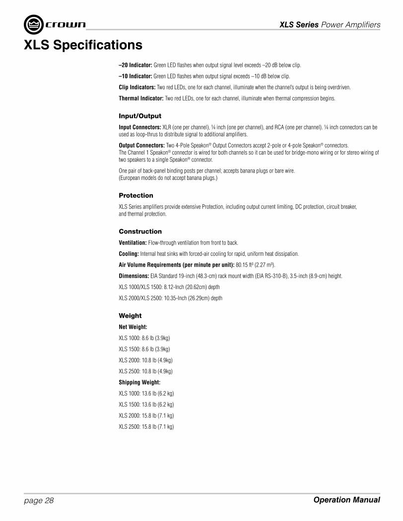
–20 Indicator: Green LED fl ashes when output signal level exceeds –20 dB below clip.
–10 Indicator: Green LED fl ashes when output signal exceeds –10 dB below clip.
Clip Indicators: Two red LEDs, one for each channel, illuminate when the channel’s output is being overdriven.
Thermal Indicator: Two red LEDs, one for each channel, illuminate when thermal compression begins.
Input/Output
Input Connectors: XLR (one per channel), ¼ inch (one per channel), and RCA (one per channel). ¼ inch connectors can be
used as loop-thrus to distribute signal to additional amplifi ers.
Output Connectors: Two 4-Pole Speakon® Output Connectors accept 2-pole or 4-pole Speakon® connectors.
The Channel 1 Speakon® connector is wired for both channels so it can be used for bridge-mono wiring or for stereo wiring of
two speakers to a single Speakon® connector.
One pair of back-panel binding posts per channel; accepts banana plugs or bare wire.
(European models do not accept banana plugs.)
Protection
XLS Series amplifi ers provide extensive Protection, including output current limiting, DC protection, circuit breaker,
and thermal protection.
Construction
Ventilation: Flow-through ventilation from front to back.
Cooling: Internal heat sinks with forced-air cooling for rapid, uniform heat dissipation.
Air Volume Requirements (per minute per unit): 80.15 ft³ (2.27 m³).
Dimensions: EIA Standard 19-inch (48.3-cm) rack mount width (EIA RS-310-B), 3.5-inch (8.9-cm) height.
XLS 1000/XLS 1500: 8.12-Inch (20.62cm) depth
XLS 2000/XLS 2500: 10.35-Inch (26.29cm) depth
Weight
Net Weight:
XLS 1000: 8.6 lb (3.9kg)
XLS 1500: 8.6 lb (3.9kg)
XLS 2000: 10.8 lb (4.9kg)
XLS 2500: 10.8 lb (4.9kg)
Shipping Weight:
XLS 1000: 13.6 lb (6.2 kg)
XLS 1500: 13.6 lb (6.2 kg)
XLS 2000: 15.8 lb (7.1 kg)
XLS 2500: 15.8 lb (7.1 kg)
XLS Specifi cations

XLS Series Power Amplifi ers
page 29Operation Manual
Crown amplifi ers are quality units that rarely require servicing. Before returning your unit for servicing, please contact Crown
Technical Support to verify the need for servicing.
Warranty is only valid within the country in which the product was purchased.
This unit has very sophisticated circuitry which should only be serviced by a fully trained technician. This is one reason why
each unit bears the following label:
CAUTION: To prevent electric shock, do not remove covers. No user serviceable parts inside. Refer
servicing to a qualifi ed technician.
Complete the Crown Audio Factory Service Information form, in the back of this manual, when returning a Crown product
to the factory or authorized service center. The form must be included with your product inside the box or in a packing slip
envelope securely attached to the outside of the shipping carton. Do not send this form separately.
Worldwide Service
Service may be obtained from an authorized service center. (Contact your local Crown/Amcron representative or our offi ce
for a list of authorized service centers.) To obtain service, simply present the bill of sale as proof of purchase along with the
defective unit to an authorized service center. They will handle the necessary paperwork and repair.
Remember to transport your unit in the original factory pack.
US and Canada Service
Service may be obtained in one of two ways: from an authorized service center or from the factory. You may choose either. It is
important that you have your copy of the bill of sale as your proof of purchase.
Service at a US or Canada Service Center
This method usually saves the most time and effort. Simply present your bill of sale along with the defective unit to an
authorized service center to obtain service. They will handle the necessary paperwork and repair. Remember to transport the
unit in the original factory pack. A list of authorized service centers in your area can be obtained from Crown Factory Service,
or online from http://www.crownaudio.com/support/servcent.htm.
Factory Service
Crown accepts no responsibility for non-serviceable product that is sent to us for factory repair. It is the owner’s responsibility
to ensure that their product is serviceable prior to sending it to the factory. Serviceable product list is available at
http://crownweb.crownintl.com/crownrma/.
For more information, please contact us direct.
A Service Return Authorization (SRA) is required for product being sent to the factory for repair. An SRA can be completed
online at www.crownaudio.com/support/factserv.htm. If you do not have access to the web, please call Crown’s Customer
Service at 574.294.8200 or 800.342.6939 extension 8205 in North America, Puerto Rico and the Virgin Islands only.
For warranty service, we will pay for ground shipping both ways in the United States. Contact Crown Customer Service to
obtain prepaid shipping labels prior to sending the unit. Or, if you prefer, you may prepay the cost of shipping, and Crown will
reimburse you. Send copies of the shipping receipts to Crown to receive reimbursement.
Your repaired unit will be returned via UPS ground. Please contact us if other arrangements are required.
Factory Service Shipping Instructions:
1. Service Return Authorization (SRA) is required for product being sent to the factory for service. Please complete the SRA
by going to www.crownaudio.com/support/factserv.htm. If you do not have access to our website, call 1.800.342.6939,
extension 8205 and we’ll create the SRA for you.
2. See packing instructions that follow.
Service

XLS Series Power Amplifi ers
Operation Manualpage 30
3. Ship product to:
CROWN AUDIO FACTORY SERVICE
1718 W MISHAWKA RD.
ELKHART, IN 46517
4. Use a bold black marker and write the SRA number on three sides of the box.
5. Record the SRA number for future reference. The SRA number can be used to check the repair status.
Packing Instructions
Important: These instructions must be followed. If they are not followed, Crown Audio, Inc. assumes no responsibility for
damaged goods and/or accessories that are sent with your unit.
1. Fill out and include the Crown Audio Factory Service Information sheet in the back of this manual.
2. Do not ship any accessories (manuals, cords, hardware, etc.) with your unit. These items are not needed to service your
product. We will not be responsible for these items.
3. When shipping your Crown product, it is important that it has adequate protection. We recommend you use the original
pack material when returning the product for repair (Figure 9.1). If you do not have the original box, please call Crown at
800.342.6939 or 574.294.8210 and order new pack material. (Do not ship your unit in a wood or metal cabinet.)
4. If you provide your own shipping pack, the minimum recommended requirements for materials are as follows:
a. 275 P.S.I. burst test, Double-Wall carton that allows for 2-inch solid Styrofoam on all six sides of unit or 3 inches of
plastic bubble wrap on all six sides of unit.
b. Securely seal the package with an adequate carton sealing tape.
c. Do not use light boxes or “peanuts”. Damage caused by poor packaging will not be covered under warranty.
Enclose the completed Crown Audio Factory Service Information form (or securely attach it to the outside of carton)
and re-seal the shipping pack with a sturdy carton sealing tape.
Estimate Approval
Approval of estimate must be given within 30 days after being notifi ed by Crown Audio Inc. Units still in the possession of
Crown after 30 days of the estimate will become the property of Crown Audio Inc.
Payment of Non-Warranty Repairs
Payment on out-of-warranty repairs must be received within 30 days of the repair date. Units unclaimed after 30 days become
the property of Crown Audio Inc.
If you have any questions, please contact Crown Factory Service.
Crown Factory Service
1718 W. Mishawaka Rd.,
Elkhart, Indiana 46517 U.S.A.
Telephone:
574-294-8200
800-342-6939 (North America, Puerto Rico, and Virgin Islands only)
Facsimile:
574-294-8301 (Technical Support)
574-294-8124 (Factory Service)
Web site:
http://www.crownaudio.com
Service
XLS Series Power Amplifi ers
page 31Operation Manual
SUMMARY OF WARRANTYCrown International, 1718 West Mishawaka Road, Elkhart, Indiana 46517-4095 U.S.A. warrants to you, the ORIGINAL
PURCHASER and ANY SUBSEQUENT OWNER of each NEW Crown product, for a period of three (3) years from the date of
purchase by the original purchaser (the “warranty period”) that the new Crown product is free of defects in materials and
workmanship. We further warrant the new Crown product regardless of the reason for failure, except as excluded in this
Warranty.
Warranty is only valid within the country in which the product was purchased.
ITEMS EXCLUDED FROM THIS CROWN WARRANTYThis Crown Warranty is in effect only for failure of a new Crown product which occurred within the Warranty Period. It does not
cover any product which has been damaged because of any intentional misuse, accident, negligence, or loss which is covered
under any of your insurance contracts. This Crown Warranty also does not extend to the new Crown product if the serial
number has been defaced, altered, or removed.
WHAT THE WARRANTOR WILL DOWe will remedy any defect, regardless of the reason for failure (except as excluded), by repair, replacement, or refund. We may
not elect refund unless you agree, or unless we are unable to provide replacement, and repair is not practical or cannot be
timely made. If a refund is elected, then you must make the defective or malfunctioning product available to us free and clear
of all liens or other encumbrances. The refund will be equal to the actual purchase price, not including interest, insurance,
closing costs, and other fi nance charges less a reasonable depreciation on the product from the date of original purchase.
Warranty work can only be performed at our authorized service centers or at the factory. We will remedy the defect and ship the
product from the service center or our factory within a reasonable time after receipt of the defective product at our authorized
service center or our factory. All expenses in remedying the defect, including surface shipping costs in the United States, will
be borne by us. (You must bear the expense of shipping the product between any foreign country and the port of entry in the
United States including the return shipment, and all taxes, duties, and other customs fees for such foreign shipments.)
HOW TO OBTAIN WARRANTY SERVICEYou must notify us of your need for warranty service within the warranty period. All components must be shipped in a factory
pack, which, if needed, may be obtained from us free of charge. Corrective action will be taken within a reasonable time of
the date of receipt of the defective product by us or our authorized service center. If the repairs made by us or our authorized
service center are not satisfactory, notify us or our authorized service center immediately.
DISCLAIMER OF CONSEQUENTIAL AND INCIDENTAL DAMAGESYOU ARE NOT ENTITLED TO RECOVER FROM US ANY INCIDENTAL DAMAGES RESULTING FROM ANY DEFECT IN THE
NEW CROWN PRODUCT. THIS INCLUDES ANY DAMAGE TO ANOTHER PRODUCT OR PRODUCTS RESULTING FROM
SUCH A DEFECT. SOME STATES DO NOT ALLOW THE EXCLUSION OR LIMITATIONS OF INCIDENTAL OR CONSEQUENTIAL
DAMAGES, SO THE ABOVE LIMITATION OR EXCLUSION MAY NOT APPLY TO YOU.
WARRANTY ALTERATIONSNo person has the authority to enlarge, amend, or modify this Crown Warranty. This Crown Warranty is not extended by the
length of time which you are deprived of the use of the new Crown product. Repairs and replacement parts provided under the
terms of this Crown Warranty shall carry only the unexpired portion of this Crown Warranty.
DESIGN CHANGESWe reserve the right to change the design of any product from time to time without notice and with no obligation to make
corresponding changes in products previously manufactured.
LEGAL REMEDIES OF PURCHASERTHIS CROWN WARRANTY GIVES YOU SPECIFIC LEGAL RIGHTS, YOU MAY ALSO HAVE OTHER RIGHTS WHICH VARY
FROM STATE TO STATE. No action to enforce this Crown Warranty shall be commenced after expiration of the warranty period.
THIS STATEMENT OF WARRANTY SUPERSEDES ANY OTHERS CONTAINED IN THIS MANUAL FOR CROWN PRODUCTS.
12/09
Warranty — UNITED STATES & CANADA

XLS Series Power Amplifi ers
Operation Manualpage 32
SUMMARY OF WARRANTYCrown International, 1718 West Mishawaka Road, Elkhart, Indiana 46517-4095 U.S.A. warrants to you, the ORIGINAL
PURCHASER and ANY SUBSEQUENT OWNER of each NEW Crown1 product, for a period of three (3) years from the date
of purchase by the original purchaser (the “warranty period”) that the new Crown product is free of defects in materials and
workmanship, and we further warrant the new Crown product regardless of the reason for failure, except as excluded in this
Warranty.
Warranty is only valid within the country in which the product was purchased.
1Note: If your unit bears the name “Amcron,” please substitute it for the name “Crown” in this warranty.
ITEMS EXCLUDED FROM THIS CROWN WARRANTYThis Crown Warranty is in effect only for failure of a new Crown product which occurred within the Warranty Period. It does not
cover any product which has been damaged because of any intentional misuse, accident, negligence, or loss which is covered
under any of your insurance contracts. This Crown Warranty also does not extend to the new Crown product if the serial
number has been defaced, altered, or removed.
WHAT THE WARRANTOR WILL DOWe will remedy any defect, regardless of the reason for failure (except as excluded), by repair, replacement, or refund. We may
not elect refund unless you agree, or unless we are unable to provide replacement, and repair is not practical or cannot be
timely made. If a refund is elected, then you must make the defective or malfunctioning product available to us free and clear
of all liens or other encumbrances. The refund will be equal to the actual purchase price, not including interest, insurance,
closing costs, and other fi nance charges less a reasonable depreciation on the product from the date of original purchase.
Warranty work can only be performed at our authorized service centers. We will remedy the defect and ship the product from
the service center within a reasonable time after receipt of the defective product at our authorized service center.
HOW TO OBTAIN WARRANTY SERVICEYou must notify your local Crown importer of your need for warranty service within the warranty period. All components must
be shipped in the original box. Corrective action will be taken within a reasonable time of the date of receipt of the defective
product by our authorized service center. If the repairs made by our authorized service center are not satisfactory, notify our
authorized service center immediately.
DISCLAIMER OF CONSEQUENTIAL AND INCIDENTAL DAMAGESYOU ARE NOT ENTITLED TO RECOVER FROM US ANY INCIDENTAL DAMAGES RESULTING FROM ANY DEFECT IN THE
NEW CROWN PRODUCT. THIS INCLUDES ANY DAMAGE TO ANOTHER PRODUCT OR PRODUCTS RESULTING FROM SUCH
A DEFECT.
WARRANTY ALTERATIONSNo person has the authority to enlarge, amend, or modify this Crown Warranty. This Crown Warranty is not extended by the
length of time which you are deprived of the use of the new Crown product. Repairs and replacement parts provided under the
terms of this Crown Warranty shall carry only the unexpired portion of this Crown Warranty.
DESIGN CHANGESWe reserve the right to change the design of any product from time to time without notice and with no obligation to make
corresponding changes in products previously manufactured.
LEGAL REMEDIES OF PURCHASERNo action to enforce this Crown Warranty shall be commenced after expiration of the warranty period.
THIS STATEMENT OF WARRANTY SUPERSEDES ANY OTHERS CONTAINED IN THIS MANUAL FOR CROWN PRODUCTS.
12/09
Warranty — WORLDWIDE EXCEPT USA & CANADA

XLS Series Power Amplifi ers
page 33Operation Manual
PRODUCT REGISTRATION
Online registration is also available at http://crownweb.crownintl.com/webregistration.
Warranty is only valid within the country in which the product is purchased.
When this form is used to register your product, it may be mailed or faxed.
Crown Audio, Inc. Fax: 574-294-8329
1718 W Mishawaka Rd
Elkhart IN 46517
Please note that some information is required. Incomplete registrations will not be processed. * Indicates required information.
OWNER’S INFORMATION – PLEASE PRINT
* First name: ____________________________ Middle initial:______ * Last name:____________________________________________________
Company: ___________________________________________________________________________________________________________
* Mailing address: _______________________________________________________________________________________________________
* City: _____________________________________ * State:_______ * Zip Code:____________________________________________________
* Country: ____________________________ E-mail address:____________________________________________________________________
* Phone # (include area code): _____________________________________ Fax #:____________________________________________________
PRODUCT INFORMATION
* MODEL * SERIAL # * PURCHASE DATE
e.g. IT8000, CDi1000, PCC16 e.g. 800000000 mo/day/yr
____________________________________ _____________________________ ____ / ____ / ____
____________________________________ _____________________________ ____ / ____ / ____
____________________________________ _____________________________ ____ / ____ / ____
____________________________________ _____________________________ ____ / ____ / ____
Product purchased from: *(Business/Individual) _______________________________________ Country:____________________________________
Comments: ___________________________________________________________________________________________________________
____________________________________________________________________________________________________________________
____________________________________________________________________________________________________________________
Crown Audio, Inc.
1718 W. Mishawaka Rd.
Elkhart, IN 46517-9439
Phone: 574-294-8000
Fax: 574-294-8329
www.crownaudio.com
CUT
ON T
HIS
LINE


XLS Series Power Amplifi ers
page 35Operation Manual
Crown Audio Factory Service InformationShipping Address: Crown Audio Factory Service, 1718 W. Mishawaka Rd., Elkhart, IN 46517
PLEASE PRINT CLEARLY
SRA #: ______________________ (If sending product to Crown factory service.)
Model: ______________________ Serial Number: _________________________ Purchase Date: ____________________
PRODUCT RETURN INFORMATION
Individual or Business Name: ___________________________________________________________________________________________________
Phone #: ____________________________ Fax #:__________________________________ E-Mail:________________________________________
Street Address (please, no P.O. Boxes): ____________________________________________________________________________________________
City: ___________________________ State/Prov:_______________ Postal Code: ________________ Country:________________________________
Nature of problem: __________________________________________________________________________________________________________
________________________________________________________________________________________________________________________
________________________________________________________________________________________________________________________
________________________________________________________________________________________________________________________
________________________________________________________________________________________________________________________
Other equipment in your system: ________________________________________________________________________________________________
If warranty is expired, please provide method of payment. Proof of purchase may be required to validate warranty.
PAYMENT OPTIONS
I have open account payment terms. Purchase order required. PO#: _____________________________ COD
Credit Card (Information below is required; however if you do not want to provide this information at this time, we will contact you when your unit is repaired for the
information.)
Credit card information:
Type of credit card: MasterCard Visa American Express Discover
Type of credit card account: Personal/Consumer Business/Corporate
Card # _______________________________________ Exp. date: ________________ *Card ID #: _______
* Card ID # is located on the back of the card following the credit card #, in the signature area. On American Express, it may be located on the front of the card. This number is required to
process the charge to your account. If you do not want to provide it at this time, we will call you to obtain this number when the repair of your unit is complete.
Name on credit card: _____________________________________
Billing address of credit card: ______________________________
______________________________
______________________________


XLS Series Power Amplifi ers
page 37Operation Manual
Notes