XLB-4232 DC - Seaway Scaffold
116
Operation and Maintenance Manual XLB-4232 DC Hydraulic Boom Lift B33-01-0088 AERIAL WORK PLATFORMS AERIAL WORK PLATFORMS AERIAL WORK PLATFORMS AERIAL WORK PLATFORMS
Transcript of XLB-4232 DC - Seaway Scaffold
Operation and Maintenance Manual
XLB-4232 DC Hydraulic Boom Lift
B33-01-0088
AERIAL WORK PLATFORMSAERIAL WORK PLATFORMSAERIAL WORK PLATFORMSAERIAL WORK PLATFORMS
BOOM PERSONNEL LIFT This equipment is designed and manufactured in compliance with the duties, responsibilities, and standards set forth for manufacturers in the ANSI 92.2 standard in effect at the time of manufacture.
This equipment will meet or exceed applicable OSHA codes and ANSI A92.2 standards when used in accordance with sections 7, 8, 9, 10 & 11 of ANSI A92.2 and all other manufacturer’s recommendations.
It is the responsibility of the user of this equipment to follow all applicable ANSI, OSHA, Federal, State, and local codes and regulations that govern the safe operation of this equipment.
i
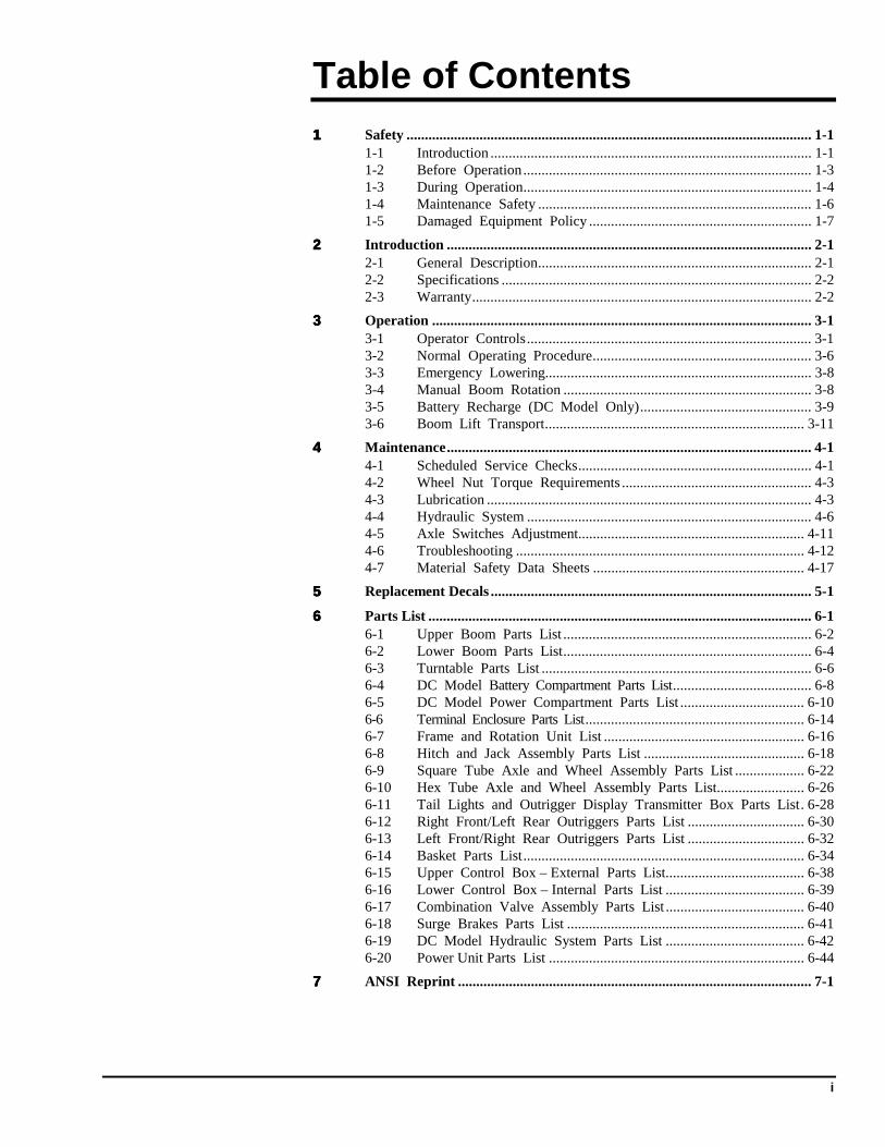
Table of Contents 1111 Safety ............................................................................................................... 1-1
1-1 Introduction ........................................................................................ 1-1 1-2 Before Operation............................................................................... 1-3 1-3 During Operation............................................................................... 1-4 1-4 Maintenance Safety ........................................................................... 1-6 1-5 Damaged Equipment Policy ............................................................. 1-7
2222 Introduction .................................................................................................... 2-1 2-1 General Description........................................................................... 2-1 2-2 Specifications ..................................................................................... 2-2 2-3 Warranty............................................................................................. 2-2
3333 Operation ........................................................................................................ 3-1 3-1 Operator Controls.............................................................................. 3-1 3-2 Normal Operating Procedure............................................................ 3-6 3-3 Emergency Lowering......................................................................... 3-8 3-4 Manual Boom Rotation .................................................................... 3-8 3-5 Battery Recharge (DC Model Only)............................................... 3-9 3-6 Boom Lift Transport....................................................................... 3-11
4444 Maintenance.................................................................................................... 4-1 4-1 Scheduled Service Checks................................................................ 4-1 4-2 Wheel Nut Torque Requirements .................................................... 4-3 4-3 Lubrication ......................................................................................... 4-3 4-4 Hydraulic System .............................................................................. 4-6 4-5 Axle Switches Adjustment.............................................................. 4-11 4-6 Troubleshooting ............................................................................... 4-12 4-7 Material Safety Data Sheets .......................................................... 4-17
5555 Replacement Decals ........................................................................................ 5-1
6666 Parts List ......................................................................................................... 6-1 6-1 Upper Boom Parts List .................................................................... 6-2 6-2 Lower Boom Parts List.................................................................... 6-4 6-3 Turntable Parts List .......................................................................... 6-6 6-4 DC Model Battery Compartment Parts List...................................... 6-8 6-5 DC Model Power Compartment Parts List .................................. 6-10 6-6 Terminal Enclosure Parts List............................................................ 6-14 6-7 Frame and Rotation Unit List ....................................................... 6-16 6-8 Hitch and Jack Assembly Parts List ............................................ 6-18 6-9 Square Tube Axle and Wheel Assembly Parts List ................... 6-22 6-10 Hex Tube Axle and Wheel Assembly Parts List........................ 6-26 6-11 Tail Lights and Outrigger Display Transmitter Box Parts List. 6-28 6-12 Right Front/Left Rear Outriggers Parts List ................................ 6-30 6-13 Left Front/Right Rear Outriggers Parts List ................................ 6-32 6-14 Basket Parts List............................................................................. 6-34 6-15 Upper Control Box – External Parts List...................................... 6-38 6-16 Lower Control Box – Internal Parts List ...................................... 6-39 6-17 Combination Valve Assembly Parts List ...................................... 6-40 6-18 Surge Brakes Parts List ................................................................. 6-41 6-19 DC Model Hydraulic System Parts List ...................................... 6-42 6-20 Power Unit Parts List ...................................................................... 6-44
7777 ANSI Reprint ................................................................................................. 7-1
ii
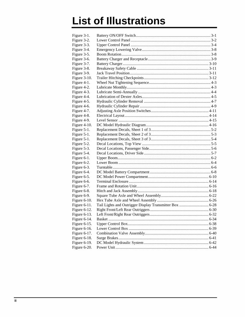
List of Illustrations Figure 3-1. Battery ON/OFF Switch.......................................................................... 3-1 Figure 3-2. Lower Control Panel ............................................................................... 3-2 Figure 3-3. Upper Control Panel ............................................................................... 3-4 Figure 3-4. Emergency Lowering Valve.................................................................... 3-8 Figure 3-5. Boom Rotation........................................................................................ 3-8 Figure 3-6. Battery Charger and Receptacle.............................................................. 3-9 Figure 3-7. Battery Charger..................................................................................... 3-10 Figure 3-8. Breakaway Safety Cable ....................................................................... 3-11 Figure 3-9. Jack Travel Position.............................................................................. 3-11 Figure 3-10. Trailer Hitching Checkpoints................................................................ 3-12 Figure 4-1. Wheel Nut Tightening Sequence............................................................. 4-3 Figure 4-2. Lubricate Monthly................................................................................... 4-3 Figure 4-3. Lubricate Semi-Annually ........................................................................ 4-4 Figure 4-4. Lubrication of Dexter Axles.................................................................... 4-5 Figure 4-5. Hydraulic Cylinder Removal .................................................................. 4-7 Figure 4-6. Hydraulic Cylinder Repair ...................................................................... 4-9 Figure 4-7. Adjusting Axle Position Switches......................................................... 4-11 Figure 4-8. Electrical Layout ................................................................................... 4-14 Figure 4-9. Level Sensor ......................................................................................... 4-15 Figure 4-10. DC Model Hydraulic Diagram.............................................................. 4-16 Figure 5-1. Replacement Decals, Sheet 1 of 3........................................................... 5-2 Figure 5-1. Replacement Decals, Sheet 2 of 3........................................................... 5-3 Figure 5-1. Replacement Decals, Sheet 3 of 3........................................................... 5-4 Figure 5-2. Decal Locations, Top View .................................................................... 5-5 Figure 5-3. Decal Locations, Passenger Side............................................................. 5-6 Figure 5-4. Decal Locations, Driver Side .................................................................. 5-7 Figure 6-1. Upper Boom............................................................................................ 6-2 Figure 6-2. Lower Boom ........................................................................................... 6-4 Figure 6-3. Turntable................................................................................................. 6-6 Figure 6-4. DC Model Battery Compartment ............................................................ 6-8 Figure 6-5. DC Model Power Compartment............................................................ 6-10 Figure 6-6. Terminal Enclosure............................................................................... 6-14 Figure 6-7. Frame and Rotation Unit....................................................................... 6-16 Figure 6-8. Hitch and Jack Assembly ...................................................................... 6-18 Figure 6-9. Square Tube Axle and Wheel Assembly............................................... 6-22 Figure 6-10. Hex Tube Axle and Wheel Assembly ................................................... 6-26 Figure 6-11. Tail Lights and Outrigger Display Transmitter Box ............................. 6-28 Figure 6-12. Right Front/Left Rear Outriggers .......................................................... 6-30 Figure 6-13. Left Front/Right Rear Outriggers .......................................................... 6-32 Figure 6-14. Basket ................................................................................................... 6-34 Figure 6-15. Upper Control Box................................................................................ 6-38 Figure 6-16. Lower Control Box ............................................................................... 6-39 Figure 6-17. Combination Valve Assembly............................................................... 6-40 Figure 6-18. Surge Brakes ......................................................................................... 6-41 Figure 6-19. DC Model Hydraulic System ................................................................ 6-42 Figure 6-20. Power Unit ............................................................................................ 6-44
iii
List of Tables Table 1-1. Minimum Safe Approach Distances ....................................................... 1-4 Table 2-1. Specifications.......................................................................................... 2-2 Table 4-1. Daily/Weekly Service Checks ................................................................ 4-1 Table 4-2. Monthly Service Checks ......................................................................... 4-2 Table 4-3. Troubleshooting Chart .......................................................................... 4-12 Table 4-7. Level Sensor LEDs ............................................................................... 4-15 Table 5-1. Replacement Decals, DC Model............................................................. 5-1 Table 6-1. Upper Boom Parts List ........................................................................... 6-3 Table 6-2. Lower Boom Parts List ........................................................................... 6-5 Table 6-3. Turntable Parts List ................................................................................ 6-7 Table 6-4. DC Model Battery Compartment Parts List............................................ 6-9 Table 6-5. DC Model Power Compartment Parts List ........................................... 6-11 Table 6-6. Terminal Enclosure Parts List............................................................... 6-15 Table 6-7. Frame and Rotation Unit Parts List ...................................................... 6-17 Table 6-8. Hitch and Jack Assembly Parts List...................................................... 6-19 Table 6-9. Square Tube Axle and Wheel Assembly Parts List .............................. 6-23 Table 6-10. Hex Tube Axle and Wheel Assembly Parts List................................... 6-27 Table 6-11. Tail Lights and Outrigger Display Transmitter Box Parts List ............. 6-29 Table 6-12. Right Front/Left Rear Outriggers Parts List.......................................... 6-31 Table 6-13. Left Front/Right Rear Outriggers Parts List.......................................... 6-33 Table 6-14. Basket Parts List ................................................................................... 6-35 Table 6-15. Upper Control Box Parts List ............................................................... 6-38 Table 6-16. Lower Control Box Parts List ............................................................... 6-39 Table 6-17. Combination Valve Assembly Parts List .............................................. 6-40 Table 6-18. Surge Brakes Parts List......................................................................... 6-41 Table 6-19. DC Model Hydraulic System Parts List................................................ 6-43 Table 6-20. Power Unit Parts List............................................................................ 6-45 Table 7-1. Minimum Safe Approach Distance (M.S.A.D.) to energized (exposed or insulated) power lines and parts. ....................................... 7-10

iv
1-1
1111 Safety
1-1 INTRODUCTION Familiarity and proper training are required for the safe operation of mechanical equipment. Equipment operated improperly or by untrained personnel can be dangerous. Read the operating instructions in this manual and become familiar with the location and proper use of all controls. Inexperienced operators should receive instruction from someone familiar with the equipment before being allowed to operate the machine. The use of intelligence and common sense in the operation of mechanical equipment is the best practice in any safety policy. Be professional and always observe the safety procedures set forth in this manual.
All OSHA, ANSI, state, and local codes and regulations pertaining to this equipment should be obtained, read, and thoroughly understood before attempting to operate this equipment. Persons under the influence of drugs, alcohol, or prescription medication should not be on or near this equipment. Common sense should be implemented at all times during the use of this equipment. Do not operate this equipment in areas where the equipment or user may come in contact with a live power source.
The information contained herein is not to be considered as legal advice and is intended for informational purposes only. This information is offered to alert Bil-Jax customers to procedures that may be of concern to them.
This information is not intended to be all inclusive and is to be followed in the use of Bil-Jax equipment only.
For any questions concerning the safe use of this equipment, call 419.445.9675 before operating.
XLB-4232 DC
1-2
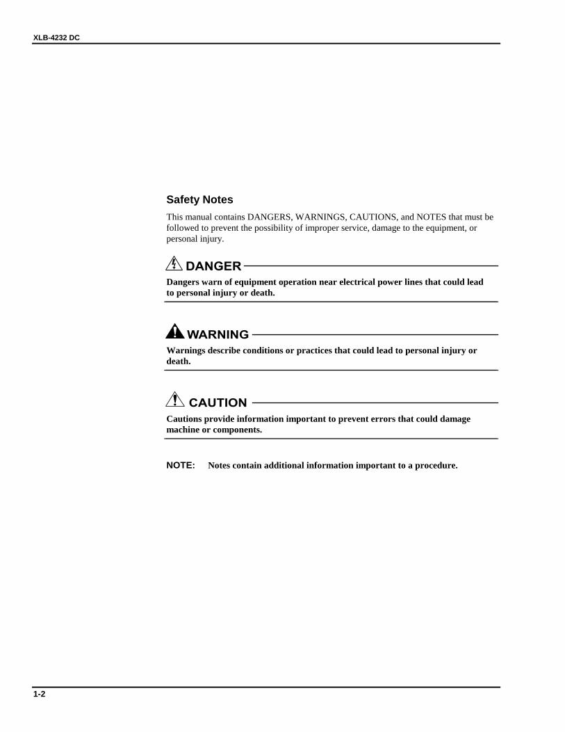
Safety Notes This manual contains DANGERS, WARNINGS, CAUTIONS, and NOTES that must be followed to prevent the possibility of improper service, damage to the equipment, or personal injury.
DANGER Dangers warn of equipment operation near electrical power lines that could lead to personal injury or death.
WARNING Warnings describe conditions or practices that could lead to personal injury or death.
CAUTION Cautions provide information important to prevent errors that could damage machine or components.
NOTE: Notes contain additional information important to a procedure.
1 — SAFETY
1-3
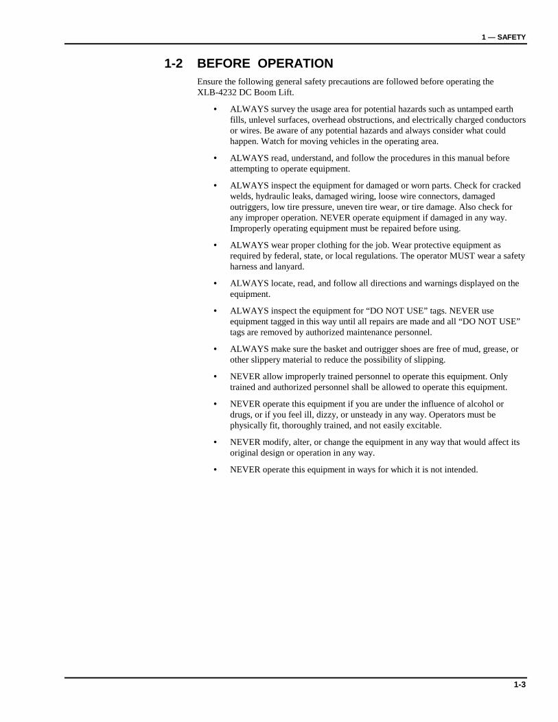
1-2 BEFORE OPERATION Ensure the following general safety precautions are followed before operating the XLB-4232 DC Boom Lift.
• ALWAYS survey the usage area for potential hazards such as untamped earth fills, unlevel surfaces, overhead obstructions, and electrically charged conductors or wires. Be aware of any potential hazards and always consider what could happen. Watch for moving vehicles in the operating area.
• ALWAYS read, understand, and follow the procedures in this manual before attempting to operate equipment.
• ALWAYS inspect the equipment for damaged or worn parts. Check for cracked welds, hydraulic leaks, damaged wiring, loose wire connectors, damaged outriggers, low tire pressure, uneven tire wear, or tire damage. Also check for any improper operation. NEVER operate equipment if damaged in any way. Improperly operating equipment must be repaired before using.
• ALWAYS wear proper clothing for the job. Wear protective equipment as required by federal, state, or local regulations. The operator MUST wear a safety harness and lanyard.
• ALWAYS locate, read, and follow all directions and warnings displayed on the equipment.
• ALWAYS inspect the equipment for “DO NOT USE” tags. NEVER use equipment tagged in this way until all repairs are made and all “DO NOT USE” tags are removed by authorized maintenance personnel.
• ALWAYS make sure the basket and outrigger shoes are free of mud, grease, or other slippery material to reduce the possibility of slipping.
• NEVER allow improperly trained personnel to operate this equipment. Only trained and authorized personnel shall be allowed to operate this equipment.
• NEVER operate this equipment if you are under the influence of alcohol or drugs, or if you feel ill, dizzy, or unsteady in any way. Operators must be physically fit, thoroughly trained, and not easily excitable.
• NEVER modify, alter, or change the equipment in any way that would affect its original design or operation in any way.
• NEVER operate this equipment in ways for which it is not intended.
XLB-4232 DC
1-4
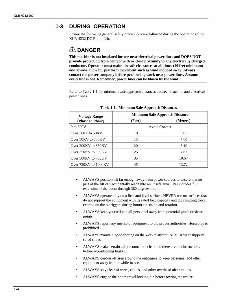
1-3 DURING OPERATION Ensure the following general safety precautions are followed during the operation of the XLB-4232 DC Boom Lift.
DANGER This machine is not insulated for use near electrical power lines and DOES NOT provide protection from contact with or close proximity to any electrically charged conductor. Operator must maintain safe clearances at all times (10 feet minimum) and always allow for platform movement such as wind induced sway. Always contact the power company before performing work near power lines. Assume every line is hot. Remember, power lines can be blown by the wind.
Refer to Table 1-1 for minimum safe approach distances between machine and electrical power lines.
Table 1-1. Minimum Safe Approach Distances
Minimum Safe Approach Distance Voltage Range (Phase to Phase) (Feet) (Meters)
0 to 300V Avoid Contact Over 300V to 50KV 10 3.05 Over 50KV to 200KV 15 4.60 Over 200KV to 350KV 20 6.10 Over 350KV to 500KV 25 7.62 Over 500KV to 750KV 35 10.67 Over 750KV to 1000KV 45 13.72
• ALWAYS position lift far enough away from power sources to ensure that no part of the lift can accidentally reach into an unsafe area. This includes full extension of the boom through 360 degrees rotation.
• ALWAYS operate only on a firm and level surface. NEVER use on surfaces that do not support the equipment with its rated load capacity and the resulting force exerted on the outriggers during boom extension and rotation.
• ALWAYS keep yourself and all personnel away from potential pinch or shear points.
• ALWAYS report any misuse of equipment to the proper authorities. Horseplay is prohibited.
• ALWAYS maintain good footing on the work platform. NEVER wear slippery soled shoes.
• ALWAYS make certain all personnel are clear and there are no obstructions before repositioning basket.
• ALWAYS cordon off area around the outriggers to keep personnel and other equipment away from it while in use.
• ALWAYS stay clear of wires, cables, and other overhead obstructions.
• ALWAYS engage the boom travel locking pin before towing the trailer.
1 — SAFETY
1-5
• NEVER allow electrode contact with any part of the basket if welding is being performed from the platform.
• NEVER use without the outriggers fully extended, locked, and firmly based. When on soft surfaces, ALWAYS use outrigger base plates.
• NEVER override or by-pass manufacturer's safety devices.
• NEVER attach a safety harness to an adjacent structure, pole, or equipment while working from the boom platform.
• NEVER release outrigger locks or move unit with a person or materials on board.
• NEVER release the outriggers or move the trailer with the boom extended.
• NEVER stand or sit on cage bars. Work only within the work cage and do not lean out over the cage to perform work.
• NEVER attempt to increase working height with boxes, ladders, or other means.
• NEVER operate this equipment when exposed to high winds, thunderstorms, ice, or any other weather conditions that would compromise operator safety.
• NEVER allow ropes, electric cords, hoses, etc. to become entangled in the equipment when the basket is being raised or lowered.
• NEVER exceed manufacturer's load limits or use the lift as a crane for lifting heavy materials. Make sure all tools and equipment are safely stowed.
• NEVER exceed load ratings by transferring loads to the basket at elevated heights.
• NEVER use cage to carry materials and never allow overhang of materials when raising or lowering the basket.
• NEVER push or pull with the boom or basket and NEVER use the boom to lift any part of the trailer.
• NEVER use the boom or basket to place a “dead man” load against any structure, materials, or equipment.
• NEVER climb up or down boom.
• NEVER leave the keys in the boom lift while unattended or not in use.

XLB-4232 DC
1-6
1-4 MAINTENANCE SAFETY Ensure the following safety precautions are observed whenever maintenance is performed on the XLB-4232 DC Boom Lift.
General Maintenance • ALWAYS perform maintenance procedures according to manufacturer's
requirements. NEVER short change maintenance procedures.
• ALWAYS check hydraulic system. Make sure all lines, connectors, and fittings are tight and in good condition.
• ALWAYS turn the MASTER POWER switch OFF before connecting or disconnecting wiring to or from valve solenoids or other load devices.
• ALWAYS disconnect power to the hydraulic pump drive motor before making electrical checks of the hydraulic valves.
• ALWAYS keep all mechanisms properly adjusted and lubricated according to maintenance schedule and manufacturer’s specifications.
• ALWAYS perform a function check of operating controls before each use and after repairs have been made.
• ALWAYS locate and protect against possible pinch points prior to performing maintenance and repairs.
• ALWAYS use factory-approved parts to repair or maintain this equipment. If this equipment is rebuilt, retesting is required in accordance with factory instructions.
• NEVER allow water or foreign particles into the DC electric motor housing. Ingestion of water or foreign particles may cause serious damage to the motor. If the motor gets wet, oven dry the motor to remove all moisture before operating; consult motor manufacturer for drying instructions.
• NEVER test or operate the hydraulic components when another person is near the equipment.
• NEVER add unauthorized fluids to the hydraulic system or battery. Check original manufacturer specifications.
• NEVER exceed the manufacturer's recommended relief valve settings.
• NEVER touch or allow metal tools to contact static discharge sensitive electronic components. ALWAYS use static discharge prevention mats and grounding devices when handling electronic components.
• NEVER tamper with cylinder counter balance valves. Contact the Bil-Jax Service Department at 419.445.9675 if the cylinder counter balance valves need adjusting.
• NEVER attempt repairs you do not understand. Consult manufacturer if you have any questions regarding proper maintenance, specifications, or repair.

1 — SAFETY
1-7
Battery Maintenance Ensure the following general safety precautions are followed whenever performing battery maintenance on the XLB-4232 DC Boom Lift.
• ALWAYS check battery acid level daily. Check battery test indicator for proper state of charge on maintenance free batteries before using lift.
• ALWAYS wear safety glasses when working near battery.
• ALWAYS avoid contact with battery acid. Battery acid causes serious burns. Avoid contact with skin or eyes. If accidental contact occurs, flush with water and consult a physician immediately.
• ALWAYS disconnect ground cable first when removing battery.
• ALWAYS connect ground cable last when installing battery.
• ALWAYS charge batteries in open, well-ventilated areas.
• NEVER smoke when servicing battery.
• NEVER allow batteries to overcharge and boil.
• NEVER short across battery posts to check for current. NEVER break a live circuit at battery.
• NEVER jump start other vehicles using boom lift battery.
1-5 DAMAGED EQUIPMENT POLICY
Safety Statement At Bil-Jax, we are dedicated to the safety of all users of our products. Therefore, all Bil-Jax lifts are designed, manufactured and tested to comply with current applicable Federal OSHA and ANSI codes and regulations.
Damage Policy There may be occasions when a Bil-Jax lift is involved in an incident that results in structural damage to the lift. This can seriously compromise the ability of the lift to perform in a safe manner. Therefore, whenever a Bil-Jax lift is damaged structurally or when there is the possibility of structural damage (this damage may be internal and is not always visible to the naked eye), Bil-Jax requires that the lift be returned to our facility at 125 Taylor Parkway, Archbold, Ohio, for reconditioning. If you have any questions concerning what constitutes structural damage, please call the Bil-Jax Service Department at 419.445.9675.
Damage Repair Notice There may be occasions when a Bil-Jax lift is involved in an incident resulting in non-structural damage. When this occurs and repairs are made by the owner or area distributor, please notify Bil-Jax of these non-maintenance repairs and request a repair form to be filled out and returned to Bil-Jax.

XLB-4232 DC
1-8
2-1
2222 Introduction
2-1 GENERAL DESCRIPTION The XLB-4232 DC Boom Lift is designed and manufactured for positioning personnel with their tools and equipment at overhead work locations. The rated work basket load capacity is 300 lbs. for the XLB-4232. Basket elevation is by two hydraulic cylinders acting on the boom sections. A hydraulic powered motor and worm gear rotates the boom 360° around a vertical axis. The hydraulic power unit includes a reservoir, pump, and control valves.
On the battery powered (DC Model) boom lift, dual 24 Volt, 39 Amp, one horsepower, DC electric motors drive the hydraulic pump. The DC motor is powered by four 6 Volt DC, 245 Amp-hour, deep charge batteries connected in series. A 40 amp, automatic, on-board battery charger is provided for recharging the batteries at the end of each work period.
Two control panels use directional selector switches and hydraulic valves to control the direction and speed of boom lift and rotation. One set of operator controls is provided for ground operation and another set is provided for operation from the basket. Elevation and rotation controls are operational only when the moving boom section is within a programmed safe operating zone. Only one boom motion is permitted at a time, and only as long as the boom is within the safe operating zone. When a selected boom motion reaches a safe operating limit, the motion ceases and another motion must be selected within the safe operating zone.
Outrigger and wheel position interlock safety switches prevent lifting operations until the four outriggers are properly deployed and the full weight of the boom lift is loaded onto the outriggers.
Boom elevation speeds are selected from low to high by a toggle switch. A hydraulic hose failure at either retract-cylinder port will cause a velocity fuse to close and stop the return oil flow. It is strongly recommended that no one adjust or tamper with these safety devices. If service is required, please notify Bil-Jax for detailed instructions.
Emergency lowering of the basket is by a manual valve on the base of the lift cylinder. Pushing in and turning 1/4 turn manually retracts the upper boom lift cylinder. The boom may need to be manually rotated to a clear area before lowering.
The boom lift cylinders will not rust or corrode during storage since the cylinder rod is fully immersed in oil. It is important that the cylinder rods be kept clean and undamaged for the protection of the cylinder head packings.
XLB-4232 DC
2-2
2-2 SPECIFICATIONS Boom Lift Work Platform Model Number XLB-4232 DC Serial Number ________________ Manufactured by: Bil-Jax, Inc.
125 Taylor Parkway Archbold, Ohio 43502 419.445.9675
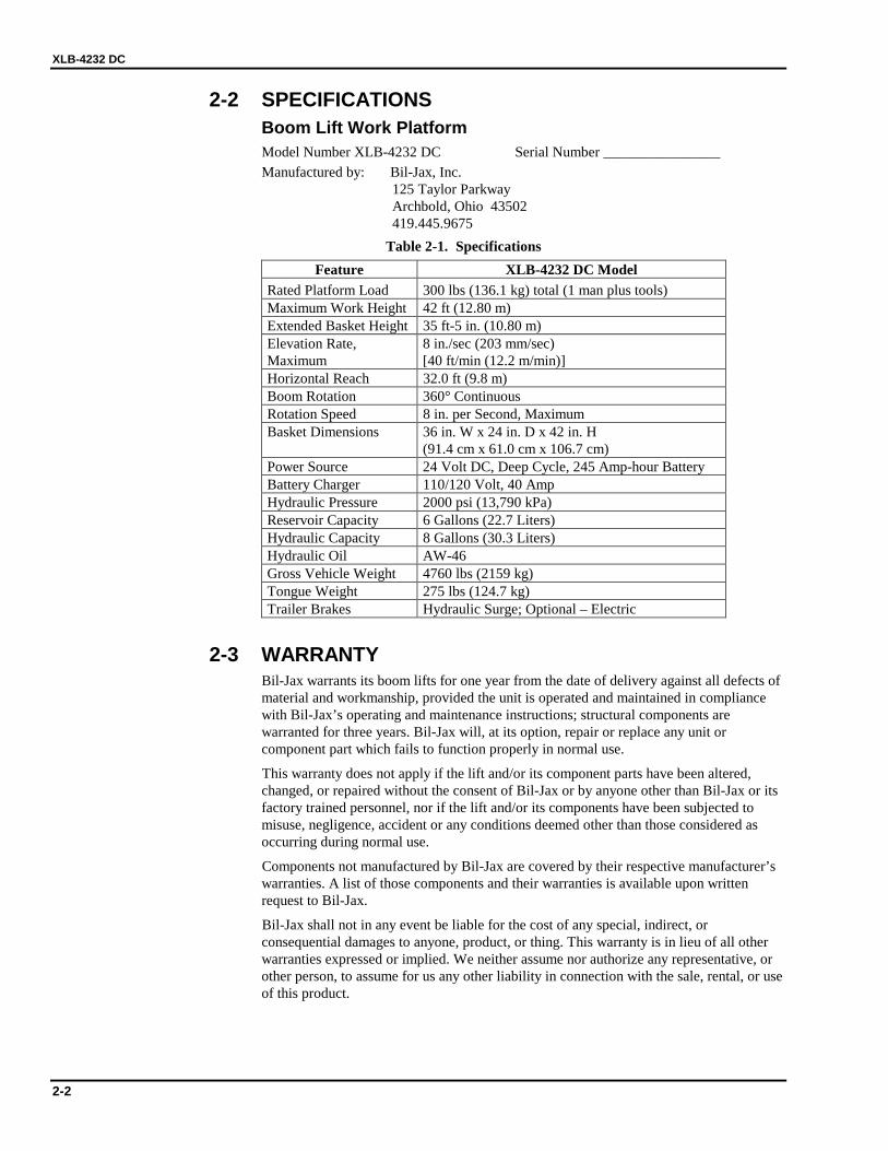
Table 2-1. Specifications Feature XLB-4232 DC Model
Rated Platform Load 300 lbs (136.1 kg) total (1 man plus tools) Maximum Work Height 42 ft (12.80 m) Extended Basket Height 35 ft-5 in. (10.80 m) Elevation Rate, Maximum
8 in./sec (203 mm/sec) [40 ft/min (12.2 m/min)]
Horizontal Reach 32.0 ft (9.8 m) Boom Rotation 360° Continuous Rotation Speed 8 in. per Second, Maximum Basket Dimensions 36 in. W x 24 in. D x 42 in. H
(91.4 cm x 61.0 cm x 106.7 cm) Power Source 24 Volt DC, Deep Cycle, 245 Amp-hour Battery Battery Charger 110/120 Volt, 40 Amp Hydraulic Pressure 2000 psi (13,790 kPa) Reservoir Capacity 6 Gallons (22.7 Liters) Hydraulic Capacity 8 Gallons (30.3 Liters) Hydraulic Oil AW-46 Gross Vehicle Weight 4760 lbs (2159 kg) Tongue Weight 275 lbs (124.7 kg) Trailer Brakes Hydraulic Surge; Optional – Electric
2-3 WARRANTY Bil-Jax warrants its boom lifts for one year from the date of delivery against all defects of material and workmanship, provided the unit is operated and maintained in compliance with Bil-Jax’s operating and maintenance instructions; structural components are warranted for three years. Bil-Jax will, at its option, repair or replace any unit or component part which fails to function properly in normal use.
This warranty does not apply if the lift and/or its component parts have been altered, changed, or repaired without the consent of Bil-Jax or by anyone other than Bil-Jax or its factory trained personnel, nor if the lift and/or its components have been subjected to misuse, negligence, accident or any conditions deemed other than those considered as occurring during normal use.
Components not manufactured by Bil-Jax are covered by their respective manufacturer’s warranties. A list of those components and their warranties is available upon written request to Bil-Jax.
Bil-Jax shall not in any event be liable for the cost of any special, indirect, or consequential damages to anyone, product, or thing. This warranty is in lieu of all other warranties expressed or implied. We neither assume nor authorize any representative, or other person, to assume for us any other liability in connection with the sale, rental, or use of this product.
3-1
3333 Operation
3-1 OPERATOR CONTROLS The XLB-4232 DC Boom Lift is equipped with multiple operator controls. Electrical boom lift and rotation control panels are located at ground level and in the basket. Manual boom rotation and lowering controls are at the ground level.
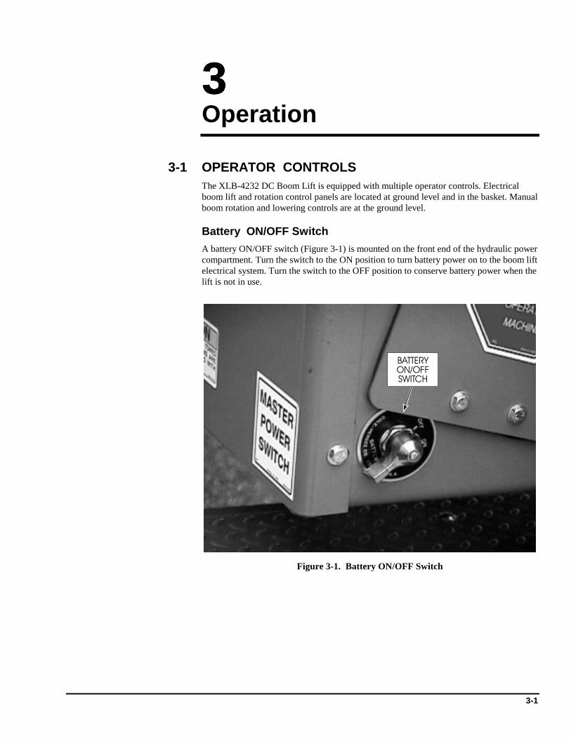
Battery ON/OFF Switch A battery ON/OFF switch (Figure 3-1) is mounted on the front end of the hydraulic power compartment. Turn the switch to the ON position to turn battery power on to the boom lift electrical system. Turn the switch to the OFF position to conserve battery power when the lift is not in use.
BATTERYON/OFFSWITCH
Figure 3-1. Battery ON/OFF Switch
XLB-4232 DC
3-2
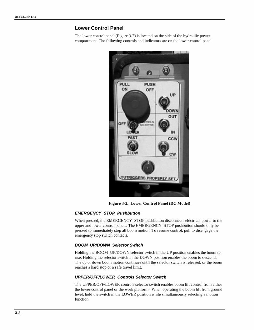
Lower Control Panel The lower control panel (Figure 3-2) is located on the side of the hydraulic power compartment. The following controls and indicators are on the lower control panel.
Figure 3-2. Lower Control Panel (DC Model)
EMERGENCY STOP Pushbutton
When pressed, the EMERGENCY STOP pushbutton disconnects electrical power to the upper and lower control panels. The EMERGENCY STOP pushbutton should only be pressed to immediately stop all boom motion. To resume control, pull to disengage the emergency stop switch contacts.
BOOM UP/DOWN Selector Switch
Holding the BOOM UP/DOWN selector switch in the UP position enables the boom to rise. Holding the selector switch in the DOWN position enables the boom to descend. The up or down boom motion continues until the selector switch is released, or the boom reaches a hard stop or a safe travel limit.
UPPER/OFF/LOWER Controls Selector Switch
The UPPER/OFF/LOWER controls selector switch enables boom lift control from either the lower control panel or the work platform. When operating the boom lift from ground level, hold the switch in the LOWER position while simultaneously selecting a motion function.
3 — OPERATION
3-3
BOOM IN/OUT Selector Switch
Holding the BOOM IN/OUT selector switch in the OUT position extends the boom out. Holding the selector switch in the IN position retracts the boom. The in or out boom motion continues until the selector switch is released, or the boom reaches a hard stop or a safe travel limit.
BOOM FAST/SLOW Selector Switch
The BOOM FAST/SLOW selector switch controls the speed of the selected boom motion. Generally, the switch is set on FAST to position the boom in the general proximity of the work area. Then, the switch is set on SLOW to fine tune the position of the boom to get closer to the work area.
ROTATION CW/CCW Selector Switch
Holding the ROTATION CW/CCW selector switch in the CW position enables the boom to rotate in the clockwise direction. Holding the selector switch in the CCW position enables the boom to rotate in the counterclockwise direction.
OUTRIGGERS Indicator
The OUTRIGGERS indicator lights up when the boom outriggers are properly deployed and the boom weight is removed from the trailer axle.
XLB-4232 DC
3-4
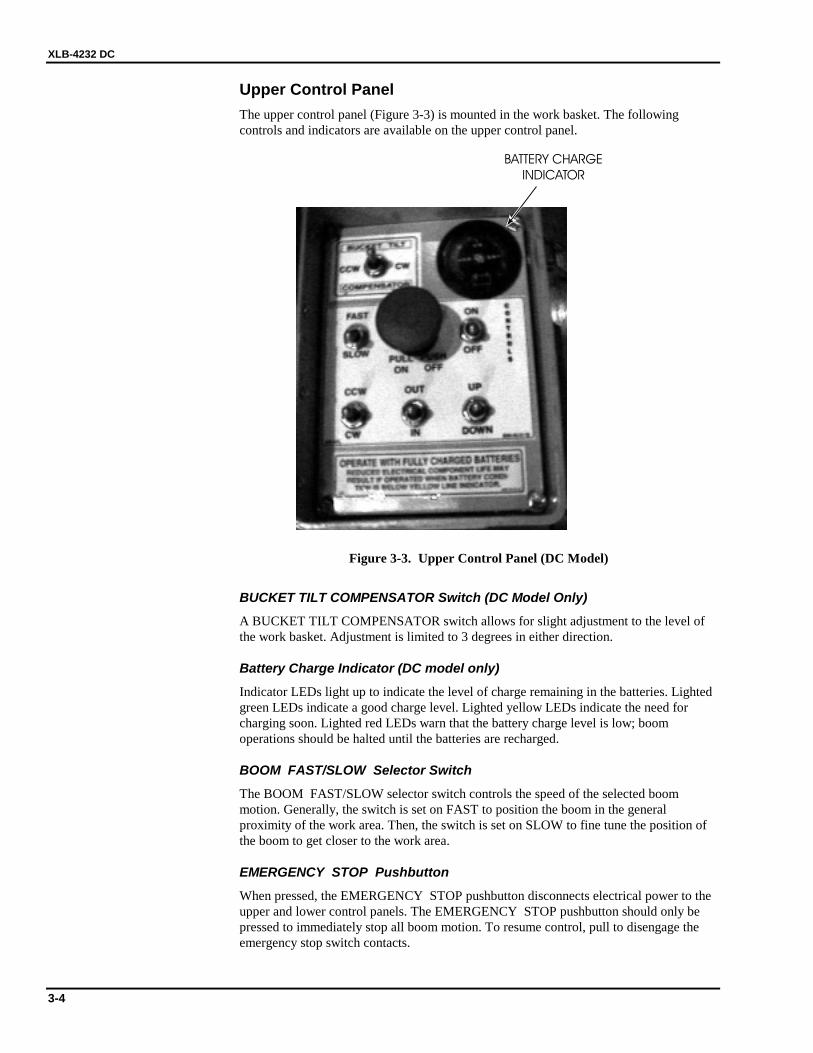
Upper Control Panel The upper control panel (Figure 3-3) is mounted in the work basket. The following controls and indicators are available on the upper control panel.
BATTERY CHARGE
INDICATOR
Figure 3-3. Upper Control Panel (DC Model)
BUCKET TILT COMPENSATOR Switch (DC Model Only)
A BUCKET TILT COMPENSATOR switch allows for slight adjustment to the level of the work basket. Adjustment is limited to 3 degrees in either direction.
Battery Charge Indicator (DC model only)
Indicator LEDs light up to indicate the level of charge remaining in the batteries. Lighted green LEDs indicate a good charge level. Lighted yellow LEDs indicate the need for charging soon. Lighted red LEDs warn that the battery charge level is low; boom operations should be halted until the batteries are recharged.
BOOM FAST/SLOW Selector Switch
The BOOM FAST/SLOW selector switch controls the speed of the selected boom motion. Generally, the switch is set on FAST to position the boom in the general proximity of the work area. Then, the switch is set on SLOW to fine tune the position of the boom to get closer to the work area.
EMERGENCY STOP Pushbutton
When pressed, the EMERGENCY STOP pushbutton disconnects electrical power to the upper and lower control panels. The EMERGENCY STOP pushbutton should only be pressed to immediately stop all boom motion. To resume control, pull to disengage the emergency stop switch contacts.
3 — OPERATION
3-5
UPPER CONTROLS ON/OFF Deadman Switch
The UPPER CONTROLS ON/OFF deadman switch must be held in the ON position simultaneously with any other boom motion function. This prevents accidental movement of the work basket.
ROTATION CW/CCW Selector Switch
Holding the ROTATION CW/CCW selector switch in the CW position enables the boom to rotate in the clockwise direction. Holding the selector switch in the CCW position enables the boom to rotate in the counterclockwise direction.
BOOM IN/OUT Selector Switch
Holding the BOOM IN/OUT selector switch in the OUT position extends the boom out. Holding the selector switch in the IN position retracts the boom. The in or out boom motion continues until the selector switch is released, or the boom reaches a hard stop or a safe travel limit.
BOOM UP/DOWN Selector Switch
Holding the BOOM UP/DOWN selector switch in the UP position enables the boom to rise. Holding the selector switch in the DOWN position enables the boom to descend. The up or down boom motion continues until the selector switch is released, or the boom reaches a hard stop or a safe travel limit.

XLB-4232 DC
3-6
3-2 NORMAL OPERATING PROCEDURE Perform the following procedures to operate the XLB-4232 DC Boom Lift.
1. Read and follow all safety precautions contained in Section 1 and all responsibilities outlined in the ANSI A92.2 reprint contained in Section 7 of this manual.
2. Position the lift at the work area. Make sure the lift is on a firm and level surface and that there are no potential hazards such as overhead obstructions or electrically charged conductors. Do not operate the lift if such hazards exist.
3. Check the tow trailer and boom lift for damaged or worn parts. Repair or replace parts as necessary. Do not use a damaged boom lift.
4. Lower the trailer tongue jack and unhitch the trailer from the tow vehicle. The trailer must be unhitched before the outriggers are deployed.
5. Deploy the boom lift outriggers as follows:
a. Lift up on the locking pin and slide each outrigger out from the trailer frame. Slide the outriggers out until the locking pins engage again.
b. Pull out the quick-adjust jack pins and lower the jack feet. With the jack feet near the ground, reinstall the jack pins at the lowest available setting.
c. Turn the BATTERY ON/OFF switch to the ON position. Lift the bubble level cover plate in front of the boom rotation housing (slew ring housing).
d. Jack up the outriggers to evenly raise the trailer; refer to the bubble level. Raise the boom lift evenly until at least one trailer wheel is off the ground and all outrigger LED’s are lit.
e. Flip outrigger jack handles over to keep them from being damaged by falling objects or bent by lowering the boom onto them.
NOTE: An axle position switch will prevent boom operation if at least one wheel is not lifted off the ground. The load of the boom lift must be placed on the outriggers to enable power.
6. Remove the pin keeper and transport pin that secures the boom to the trailer frame. Stow the transport pin in its storage tube.
7. Unlock and open the base controls door.
8. Toggle the UPPER/OFF/LOWER controls switch to the LOWER position.
9. Use the lower control panel to operate the lift controls. Raise, lower, extend, and rotate the boom in slow speed to get familiar with the controls. Learn to smoothly start and stop the boom lift.
10. To place the basket at an easier entry height:
a. Raise the boom clear of its support post by holding the controls selector switch to LOWER position and also activating the UP function.
b. Rotate the boom clockwise from its transport position by holding the controls selector switch to LOWER position and also activate CW function. Rotate until there is clearance between the support post and the boom.
c. Lower the boom until the basket just touches the ground by holding the controls selector switch to LOWER position and also activate the DOWN function.
11. Switch the controls selector switch to UPPER controls. Control of the boom is now directed to the basket control panel.
3 — OPERATION
3-7
12. Raise the safety bar and enter the basket. Put on the safety harness and attach the lanyard to the basket railing.
13. The lift is now ready for operation from the basket. Operate in slow speed to get familiar with the controls. The UPPER CONTROLS ON/OFF deadman switch must be held in the ON position simultaneously with any other boom motion function.
14. Should the basket become tilted out of the normal vertical axis, adjustment can be made using the BUCKET TILT COMPENSATOR switch. This function is protected with a 3 degree limit safety switch in either direction.
15. Monitor the BATTERY CHARGE INDICATOR during operation and charge the batteries as necessary. (See Section 3-5)
XLB-4232 DC
3-8
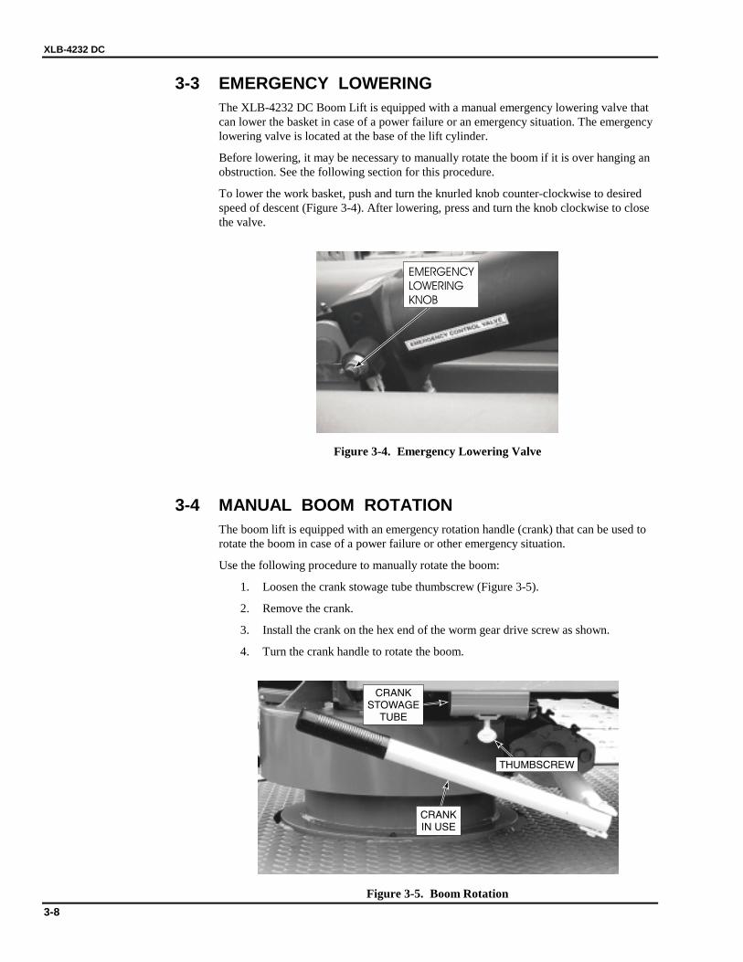
3-3 EMERGENCY LOWERING The XLB-4232 DC Boom Lift is equipped with a manual emergency lowering valve that can lower the basket in case of a power failure or an emergency situation. The emergency lowering valve is located at the base of the lift cylinder.
Before lowering, it may be necessary to manually rotate the boom if it is over hanging an obstruction. See the following section for this procedure.
To lower the work basket, push and turn the knurled knob counter-clockwise to desired speed of descent (Figure 3-4). After lowering, press and turn the knob clockwise to close the valve.
EMERGENCY
LOWERING
KNOB
Figure 3-4. Emergency Lowering Valve
3-4 MANUAL BOOM ROTATION The boom lift is equipped with an emergency rotation handle (crank) that can be used to rotate the boom in case of a power failure or other emergency situation.
Use the following procedure to manually rotate the boom:
1. Loosen the crank stowage tube thumbscrew (Figure 3-5).
2. Remove the crank.
3. Install the crank on the hex end of the worm gear drive screw as shown.
4. Turn the crank handle to rotate the boom.
CRANKSTOWAGE
TUBE
CRANKIN USE
THUMBSCREW
Figure 3-5. Boom Rotation
3 — OPERATION
3-9
3-5 BATTERY RECHARGE (DC MODEL ONLY) The DC boom lift batteries should be recharged after each 8-hour work shift or more often if needed. When the boom lift is not in use, the batteries should be recharged at least once per week.
The normal charge time is 10 to 12 hours. If the battery charge is extremely low, a full recharge may take up to 24 hours.
Recharge the DC boom lift batteries as follows:
WARNING Recharge the batteries in a well ventilated area only. Do not charge batteries near fire, flame, or other ignition sources. Batteries being charged may emit highly explosive hydrogen gas. Failure to properly ventilate the charge gases may result in serious injury or death.
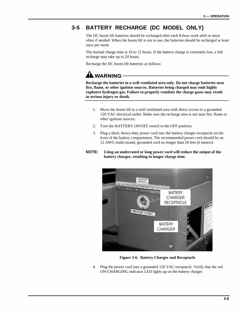
1. Move the boom lift to a well ventilated area with direct access to a grounded 120 VAC electrical outlet. Make sure the recharge area is not near fire, flame or other ignition sources.
2. Turn the BATTERY ON/OFF switch to the OFF position.
3. Plug a short, heavy-duty power cord into the battery charger receptacle on the front of the battery compartment. The recommended power cord should be an 12 AWG multi-strand, grounded cord no longer than 20 feet (6 meters).
NOTE: Using an underrated or long power cord will reduce the output of the battery charger, resulting in longer charge time.
BATTERY
CHARGER
RECEPTACLE
BATTERY
CHARGER
Figure 3-6. Battery Charger and Receptacle
4. Plug the power cord into a grounded 120 VAC receptacle. Verify that the red ON-CHARGING indicator LED lights up on the battery charger.
XLB-4232 DC
3-10
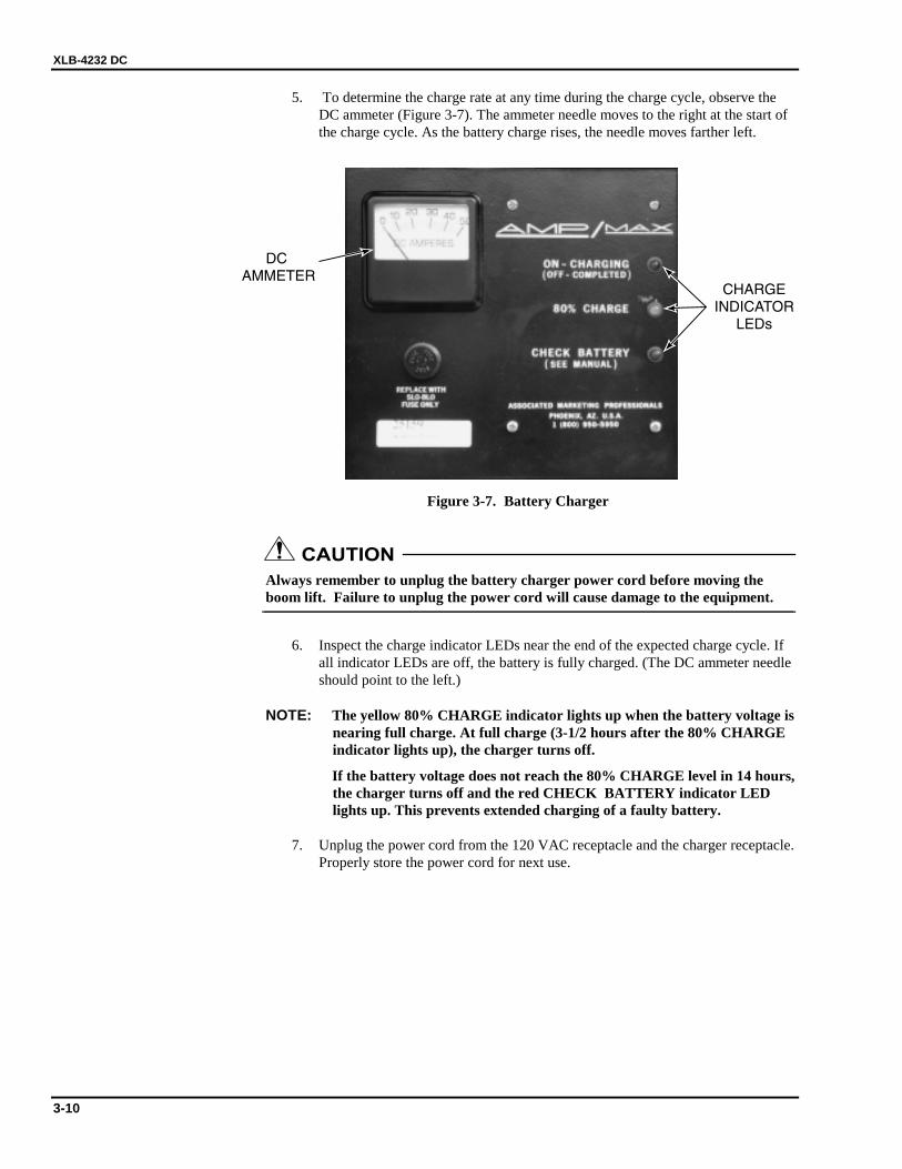
5. To determine the charge rate at any time during the charge cycle, observe the DC ammeter (Figure 3-7). The ammeter needle moves to the right at the start of the charge cycle. As the battery charge rises, the needle moves farther left.
Figure 3-7. Battery Charger
CAUTION Always remember to unplug the battery charger power cord before moving the boom lift. Failure to unplug the power cord will cause damage to the equipment.
6. Inspect the charge indicator LEDs near the end of the expected charge cycle. If all indicator LEDs are off, the battery is fully charged. (The DC ammeter needle should point to the left.)
NOTE: The yellow 80% CHARGE indicator lights up when the battery voltage is nearing full charge. At full charge (3-1/2 hours after the 80% CHARGE indicator lights up), the charger turns off.
If the battery voltage does not reach the 80% CHARGE level in 14 hours, the charger turns off and the red CHECK BATTERY indicator LED lights up. This prevents extended charging of a faulty battery.
7. Unplug the power cord from the 120 VAC receptacle and the charger receptacle. Properly store the power cord for next use.
3 — OPERATION
3-11
3-6 BOOM LIFT TRANSPORT The boom lift trailer is a single axle trailer fitted with a two-inch ball hitch, surge brakes, breakaway safety cable, safety chains, brake lights, and side marker lights. Proper boom lift transport requires the correct hookup and inspection of these trailer components before towing. Use the following procedures to hitch, tow, and back the boom lift trailer:
Trailer Hitching Trailer hitching requires a second person to give tow vehicle backing instructions.
1. Back the tow vehicle to the trailer. Verify that the ball and hitch are in line and that the trailer hitch will clear the ball. Jack up the tongue as needed.
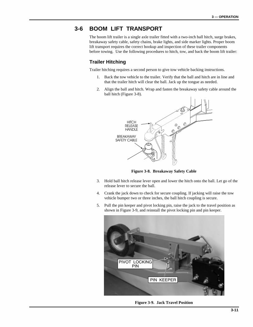
2. Align the ball and hitch. Wrap and fasten the breakaway safety cable around the ball hitch (Figure 3-8).
BREAKAWAYSAFETY CABLE
HITCHRELEASEHANDLE
Figure 3-8. Breakaway Safety Cable
3. Hold ball hitch release lever open and lower the hitch onto the ball. Let go of the release lever to secure the ball.
4. Crank the jack down to check for secure coupling. If jacking will raise the tow vehicle bumper two or three inches, the ball hitch coupling is secure.
5. Pull the pin keeper and pivot locking pin, raise the jack to the travel position as shown in Figure 3-9, and reinstall the pivot locking pin and pin keeper.
Figure 3-9. Jack Travel Position
XLB-4232 DC
3-12
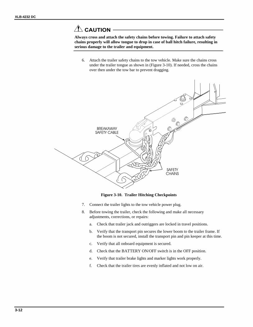
CAUTION Always cross and attach the safety chains before towing. Failure to attach safety chains properly will allow tongue to drop in case of ball hitch failure, resulting in serious damage to the trailer and equipment.
6. Attach the trailer safety chains to the tow vehicle. Make sure the chains cross under the trailer tongue as shown in (Figure 3-10). If needed, cross the chains over then under the tow bar to prevent dragging.
SAFETYCHAINS
BREAKAWAYSAFETY CABLE
Figure 3-10. Trailer Hitching Checkpoints
7. Connect the trailer lights to the tow vehicle power plug.
8. Before towing the trailer, check the following and make all necessary adjustments, corrections, or repairs:
a. Check that trailer jack and outriggers are locked in travel positions.
b. Verify that the transport pin secures the lower boom to the trailer frame. If the boom is not secured, install the transport pin and pin keeper at this time.
c. Verify that all onboard equipment is secured.
d. Check that the BATTERY ON/OFF switch is in the OFF position.
e. Verify that trailer brake lights and marker lights work properly.
f. Check that the trailer tires are evenly inflated and not low on air.
3 — OPERATION
3-13
WARNING Improper tightening of boom lift trailer wheel nuts can cause wheel lugs to shear, causing serious injury or damage to equipment. Check and maintain the proper wheel nut torque according to the maintenance instructions in this manual.
Periodically check the wheel nut torque according to the instructions in Section 4-2 of this manual. More frequent torque checks are required when a wheel is recently installed.
After towing, while the trailer wheels are elevated for boom lift operation, check for loose wheels and for wheel lug wear indications. If a loose wheel mounting is indicated, remove and inspect the wheel lugs for damage. Do not tow the boom lift with worn or damaged wheel lugs.

XLB-4232 DC
3-14
4-1
4444 Maintenance
4-1 SCHEDULED SERVICE CHECKS
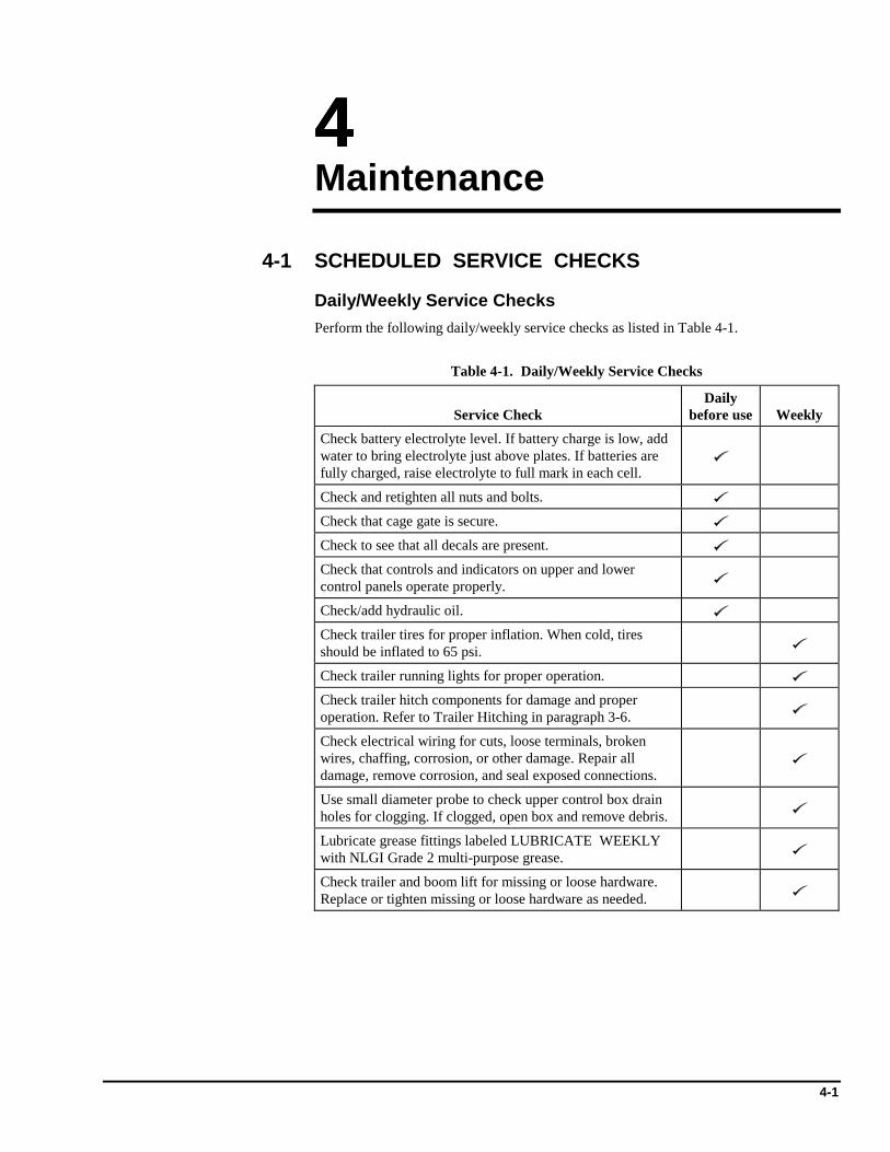
Daily/Weekly Service Checks Perform the following daily/weekly service checks as listed in Table 4-1.
Table 4-1. Daily/Weekly Service Checks
Service Check Daily
before use Weekly Check battery electrolyte level. If battery charge is low, add water to bring electrolyte just above plates. If batteries are fully charged, raise electrolyte to full mark in each cell.
Check and retighten all nuts and bolts.
Check that cage gate is secure.
Check to see that all decals are present.
Check that controls and indicators on upper and lower control panels operate properly.
Check/add hydraulic oil.
Check trailer tires for proper inflation. When cold, tires should be inflated to 65 psi.
Check trailer running lights for proper operation.
Check trailer hitch components for damage and proper operation. Refer to Trailer Hitching in paragraph 3-6.
Check electrical wiring for cuts, loose terminals, broken wires, chaffing, corrosion, or other damage. Repair all damage, remove corrosion, and seal exposed connections.
Use small diameter probe to check upper control box drain holes for clogging. If clogged, open box and remove debris.
Lubricate grease fittings labeled LUBRICATE WEEKLY with NLGI Grade 2 multi-purpose grease.
Check trailer and boom lift for missing or loose hardware. Replace or tighten missing or loose hardware as needed.

XLB-4232 DC
4-2
Monthly Service Checks Perform the following monthly service checks as listed in Table 4-2.
Table 4-2. Monthly Service Checks
Service Check
Every month
Every 6 months
Every 12 months
Clean battery terminals and check battery charger operation.
Check operation of manual emergency lowering valve.
Check wheel nut torque per paragraph 4-2.
Check for excess wear, free play, or binding in outrigger screws. Replace damaged parts.
Lubricate power compartment hinges and latches with light weight machine oil.
Lubricate grease fittings labeled LUBRICATE MONTHLY per paragraph 4-3.2.
Lubricate trailer tongue jack (2 places) with NLGI Grade 2 multi-purpose grease.
Lubricate grease fittings labeled LUBRICATE SEMI-ANNUALLY per paragraph 4-3.3.
Lubricate wheel bearings per paragraph 4-3.4.
Check battery cables and wiring for loose connections and damaged wires.
Check outrigger bushings and replace if necessary per paragraph 4-5.
Replace hydraulic oil and oil filter.
Check boom pivot points for bearing wear. Replace worn or damaged bearings.
Check slew bearing for wear or damage; torque bearing bolts to 200 lb-ft (271 N·m).
Inspect and adjust trailer brakes.
Load test boom with 300 pounds.
4 — MAINTENANCE
4-3
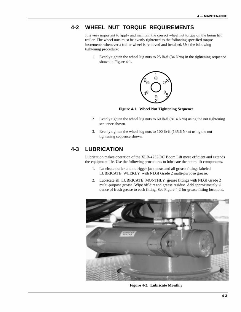
4-2 WHEEL NUT TORQUE REQUIREMENTS It is very important to apply and maintain the correct wheel nut torque on the boom lift trailer. The wheel nuts must be evenly tightened to the following specified torque increments whenever a trailer wheel is removed and installed. Use the following tightening procedure:
1. Evenly tighten the wheel lug nuts to 25 lb-ft (34 N·m) in the tightening sequence shown in Figure 4-1.
Figure 4-1. Wheel Nut Tightening Sequence
2. Evenly tighten the wheel lug nuts to 60 lb-ft (81.4 N·m) using the nut tightening sequence shown.
3. Evenly tighten the wheel lug nuts to 100 lb-ft (135.6 N·m) using the nut tightening sequence shown.
4-3 LUBRICATION Lubrication makes operation of the XLB-4232 DC Boom Lift more efficient and extends the equipment life. Use the following procedures to lubricate the boom lift components.
1. Lubricate trailer and outrigger jack posts and all grease fittings labeled LUBRICATE WEEKLY with NLGI Grade 2 multi-purpose grease.
2. Lubricate all LUBRICATE MONTHLY grease fittings with NLGI Grade 2 multi-purpose grease. Wipe off dirt and grease residue. Add approximately ½ ounce of fresh grease to each fitting. See Figure 4-2 for grease fitting locations.
Figure 4-2. Lubricate Monthly
XLB-4232 DC
4-4
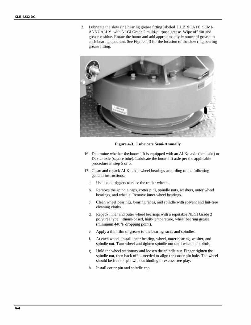
3. Lubricate the slew ring bearing grease fitting labeled LUBRICATE SEMI-ANNUALLY with NLGI Grade 2 multi-purpose grease. Wipe off dirt and grease residue. Rotate the boom and add approximately ½ ounce of grease to each bearing quadrant. See Figure 4-3 for the location of the slew ring bearing grease fitting.
Figure 4-3. Lubricate Semi-Annually
16. Determine whether the boom lift is equipped with an Al-Ko axle (hex tube) or Dexter axle (square tube). Lubricate the boom lift axle per the applicable procedure in step 5 or 6.
17. Clean and repack Al-Ko axle wheel bearings according to the following general instructions:
a. Use the outriggers to raise the trailer wheels.
b. Remove the spindle caps, cotter pins, spindle nuts, washers, outer wheel bearings, and wheels. Remove inner wheel bearings.
c. Clean wheel bearings, bearing races, and spindle with solvent and lint-free cleaning cloths.
d. Repack inner and outer wheel bearings with a reputable NLGI Grade 2 polyurea type, lithium-based, high-temperature, wheel bearing grease (minimum 440°F dropping point).
e. Apply a thin film of grease to the bearing races and spindles.
f. At each wheel, install inner bearing, wheel, outer bearing, washer, and spindle nut. Turn wheel and tighten spindle nut until wheel hub binds.
g. Hold the wheel stationary and loosen the spindle nut. Finger tighten the spindle nut, then back off as needed to align the cotter pin hole. The wheel should be free to spin without binding or excess free play.
h. Install cotter pin and spindle cap.
4 — MAINTENANCE
4-5
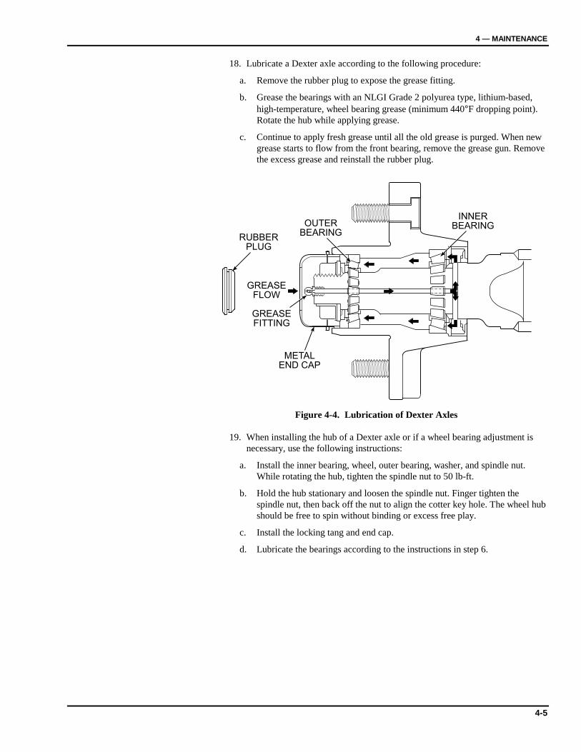
18. Lubricate a Dexter axle according to the following procedure:
a. Remove the rubber plug to expose the grease fitting.
b. Grease the bearings with an NLGI Grade 2 polyurea type, lithium-based, high-temperature, wheel bearing grease (minimum 440°F dropping point). Rotate the hub while applying grease.
c. Continue to apply fresh grease until all the old grease is purged. When new grease starts to flow from the front bearing, remove the grease gun. Remove the excess grease and reinstall the rubber plug.
INNERBEARINGOUTER
BEARING
GREASEFLOW
RUBBERPLUG
METALEND CAP
GREASEFITTING
Figure 4-4. Lubrication of Dexter Axles
19. When installing the hub of a Dexter axle or if a wheel bearing adjustment is necessary, use the following instructions:
a. Install the inner bearing, wheel, outer bearing, washer, and spindle nut. While rotating the hub, tighten the spindle nut to 50 lb-ft.
b. Hold the hub stationary and loosen the spindle nut. Finger tighten the spindle nut, then back off the nut to align the cotter key hole. The wheel hub should be free to spin without binding or excess free play.
c. Install the locking tang and end cap.
d. Lubricate the bearings according to the instructions in step 6.

XLB-4232 DC
4-6
4-4 HYDRAULIC SYSTEM Hydraulic system maintenance varies with equipment use and the environment in which the boom lift is used. Constant attention to keep the oil clean and the reservoir properly filled will help prevent possible damage to the system. Hydraulic diagrams are provided at the end of this section for general reference.
Hydraulic System Inspection Check the hydraulic hose and fittings for leaks and damage daily. Tighten or replace as necessary to prevent hydraulic oil loss.
Fluid Check and Replacement The oil level sight gage should be checked with the boom down and the trailer on a level surface. The reservoir is originally filled with AW-46, a high-grade, non-foaming hydraulic oil designed for temperatures as low as -20°F (-33°C).
Use Dextron Automatic Transmission Fluid Type A for low temperatures reaching -40°F (-40°C). If either oil is not available, a good grade SAE 10W hydraulic oil may be used where the low temperature is above 32°F (0°C). SAE 5W hydraulic oil may be used where low temperatures reaching 0°F (-18°C).
Do not mix hydraulic oils. Clean the reservoir sump strainer and replace the hydraulic oil once a year or whenever the oil becomes contaminated.
Air Bleeding Delayed response or sporadic boom lift motions may indicate air in the lift cylinders. Use the following procedure to bleed entrapped air from the hydraulic system.
1. Fill the reservoir with the proper hydraulic fluid. Replace, but do not tighten the reservoir fill cap.
2. Fully raise and lower the boom to return oil with entrapped air to the reservoir.
3. Allow several minutes for air to escape the reservoir oil.
4. Repeat steps 1 through 3 as needed. Add oil slowly and only when the boom is lowered to prevent adding more air to the system.
4 — MAINTENANCE
4-7
Hydraulic Cylinder Repair
Cylinder Removal and Installation
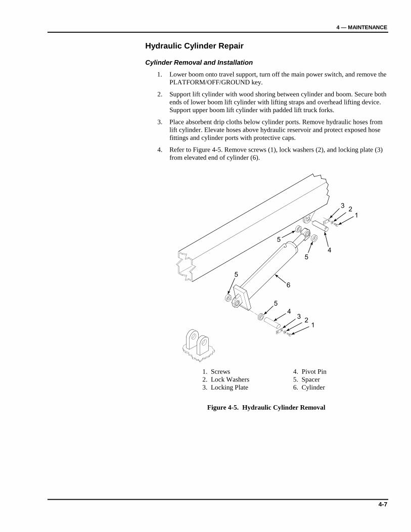
1. Lower boom onto travel support, turn off the main power switch, and remove the PLATFORM/OFF/GROUND key.
2. Support lift cylinder with wood shoring between cylinder and boom. Secure both ends of lower boom lift cylinder with lifting straps and overhead lifting device. Support upper boom lift cylinder with padded lift truck forks.
3. Place absorbent drip cloths below cylinder ports. Remove hydraulic hoses from lift cylinder. Elevate hoses above hydraulic reservoir and protect exposed hose fittings and cylinder ports with protective caps.
4. Refer to Figure 4-5. Remove screws (1), lock washers (2), and locking plate (3) from elevated end of cylinder (6).
32
1
45
5
6
5
5
43
21
Figure 4-5. Hydraulic Cylinder Removal
1. Screws 4. Pivot Pin 2. Lock Washers 5. Spacer 3. Locking Plate 6. Cylinder
XLB-4232 DC
4-8
5. Using a pry bar and shoring, unweight the cylinder end. Remove pivot pin (4) and spacers (5).
6. Lower the free end of cylinder (6) onto support shoring or a lifting strap.
7. Repeat steps 4 through 6 at the opposite end of the cylinder.
8. Lift the lower end of the cylinder from its pivot block. Use an overhead lifting device and lifting straps and/or a lift truck to remove the cylinder.
9. After repairing the hydraulic cylinder, reinstall the cylinder in the reverse order of removal.
10. Power up the hydraulic system and check for leakage. Tighten hydraulic fittings as needed.
11. Bleed entrapped air from the hydraulic cylinder according to instructions in paragraph 4-4.

4 — MAINTENANCE
4-9
Cylinder Disassembly and Inspection
Perform the following procedure to disassemble the upper or lower hydraulic lift cylinder. Whenever the hydraulic cylinder is disassembled, all seals must be replaced. Refer to replacement seal kit, Figure 6-3 or 6-4.
1. Check bearings (1, Figure 4-6) for wear and excess play. Replace bearings if necessary.
2. Unscrew headstock (2) and slide cylinder rod (3) from housing (4).
3. Remove slotted nut (5) and piston (6). Remove and discard wear ring (7), o-rings (8 and 9). Remove sleeve (10).
Figure 4-6. Hydraulic Cylinder Repair
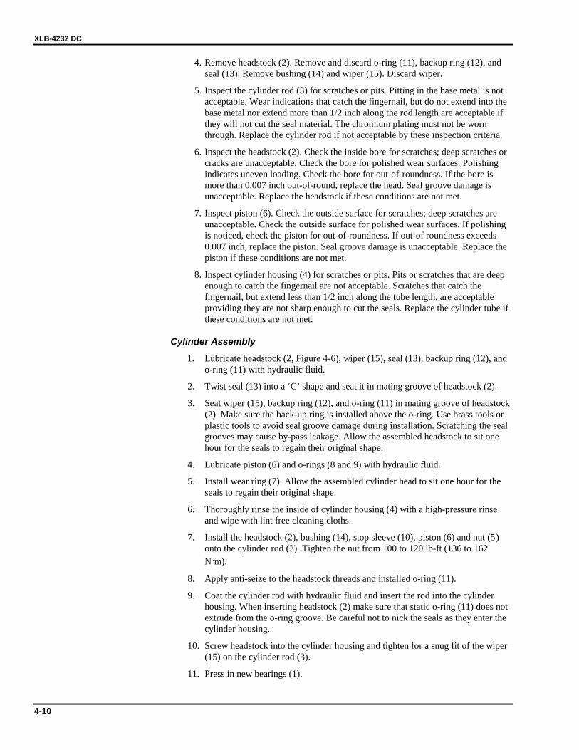
1. Bearings 2. Headstock 3. Cylinder Rod 4. Housing 5. Slotted Nut 6. Piston 7. Wear Ring 8. O-Ring 9. O-Ring 10. Sleeve 11. O-Ring 12. Backup Ring 13. Seal 14. Bushing 15. Wiper
XLB-4232 DC
4-10
4. Remove headstock (2). Remove and discard o-ring (11), backup ring (12), and seal (13). Remove bushing (14) and wiper (15). Discard wiper.
5. Inspect the cylinder rod (3) for scratches or pits. Pitting in the base metal is not acceptable. Wear indications that catch the fingernail, but do not extend into the base metal nor extend more than 1/2 inch along the rod length are acceptable if they will not cut the seal material. The chromium plating must not be worn through. Replace the cylinder rod if not acceptable by these inspection criteria.
6. Inspect the headstock (2). Check the inside bore for scratches; deep scratches or cracks are unacceptable. Check the bore for polished wear surfaces. Polishing indicates uneven loading. Check the bore for out-of-roundness. If the bore is more than 0.007 inch out-of-round, replace the head. Seal groove damage is unacceptable. Replace the headstock if these conditions are not met.
7. Inspect piston (6). Check the outside surface for scratches; deep scratches are unacceptable. Check the outside surface for polished wear surfaces. If polishing is noticed, check the piston for out-of-roundness. If out-of roundness exceeds 0.007 inch, replace the piston. Seal groove damage is unacceptable. Replace the piston if these conditions are not met.
8. Inspect cylinder housing (4) for scratches or pits. Pits or scratches that are deep enough to catch the fingernail are not acceptable. Scratches that catch the fingernail, but extend less than 1/2 inch along the tube length, are acceptable providing they are not sharp enough to cut the seals. Replace the cylinder tube if these conditions are not met.
Cylinder Assembly
1. Lubricate headstock (2, Figure 4-6), wiper (15), seal (13), backup ring (12), and o-ring (11) with hydraulic fluid.
2. Twist seal (13) into a ‘C’ shape and seat it in mating groove of headstock (2).
3. Seat wiper (15), backup ring (12), and o-ring (11) in mating groove of headstock (2). Make sure the back-up ring is installed above the o-ring. Use brass tools or plastic tools to avoid seal groove damage during installation. Scratching the seal grooves may cause by-pass leakage. Allow the assembled headstock to sit one hour for the seals to regain their original shape.
4. Lubricate piston (6) and o-rings (8 and 9) with hydraulic fluid.
5. Install wear ring (7). Allow the assembled cylinder head to sit one hour for the seals to regain their original shape.
6. Thoroughly rinse the inside of cylinder housing (4) with a high-pressure rinse and wipe with lint free cleaning cloths.
7. Install the headstock (2), bushing (14), stop sleeve (10), piston (6) and nut (5 ) onto the cylinder rod (3). Tighten the nut from 100 to 120 lb-ft (136 to 162 N·m).
8. Apply anti-seize to the headstock threads and installed o-ring (11).
9. Coat the cylinder rod with hydraulic fluid and insert the rod into the cylinder housing. When inserting headstock (2) make sure that static o-ring (11) does not extrude from the o-ring groove. Be careful not to nick the seals as they enter the cylinder housing.
10. Screw headstock into the cylinder housing and tighten for a snug fit of the wiper (15) on the cylinder rod (3).
11. Press in new bearings (1).
4 — MAINTENANCE
4-11
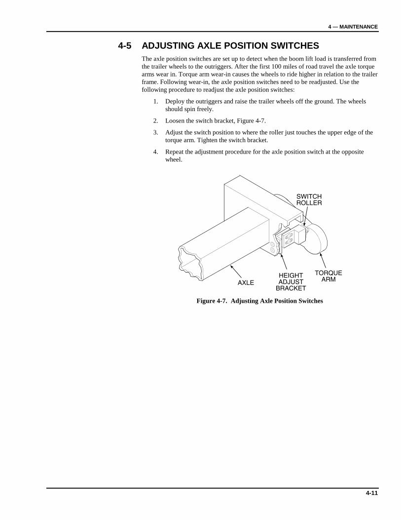
4-5 ADJUSTING AXLE POSITION SWITCHES The axle position switches are set up to detect when the boom lift load is transferred from the trailer wheels to the outriggers. After the first 100 miles of road travel the axle torque arms wear in. Torque arm wear-in causes the wheels to ride higher in relation to the trailer frame. Following wear-in, the axle position switches need to be readjusted. Use the following procedure to readjust the axle position switches:
1. Deploy the outriggers and raise the trailer wheels off the ground. The wheels should spin freely.
2. Loosen the switch bracket, Figure 4-7.
3. Adjust the switch position to where the roller just touches the upper edge of the torque arm. Tighten the switch bracket.
4. Repeat the adjustment procedure for the axle position switch at the opposite wheel.
Figure 4-7. Adjusting Axle Position Switches
XLB-4232 DC
4-12
4-6 TROUBLESHOOTING
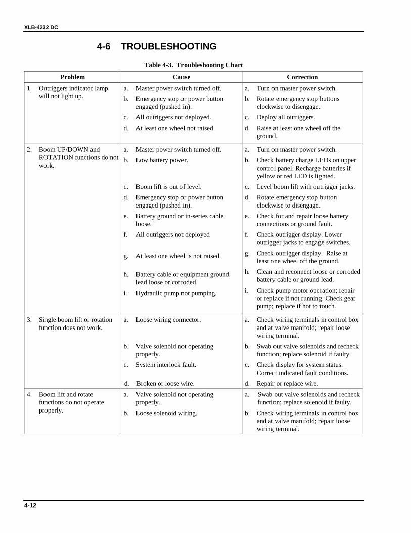
Table 4-3. Troubleshooting Chart
Problem Cause Correction 1. Outriggers indicator lamp
will not light up. a. Master power switch turned off. b. Emergency stop or power button
engaged (pushed in). c. All outriggers not deployed. d. At least one wheel not raised.
a. Turn on master power switch. b. Rotate emergency stop buttons
clockwise to disengage. c. Deploy all outriggers. d. Raise at least one wheel off the
ground.
2. Boom UP/DOWN and ROTATION functions do not work.
a. Master power switch turned off. b. Low battery power.
c. Boom lift is out of level. d. Emergency stop or power button
engaged (pushed in). e. Battery ground or in-series cable
loose. f. All outriggers not deployed g. At least one wheel is not raised.
h. Battery cable or equipment ground
lead loose or corroded. i. Hydraulic pump not pumping.
a. Turn on master power switch. b. Check battery charge LEDs on upper
control panel. Recharge batteries if yellow or red LED is lighted.
c. Level boom lift with outrigger jacks. d. Rotate emergency stop button
clockwise to disengage. e. Check for and repair loose battery
connections or ground fault. f. Check outrigger display. Lower
outrigger jacks to engage switches. g. Check outrigger display. Raise at
least one wheel off the ground. h. Clean and reconnect loose or corroded
battery cable or ground lead. i. Check pump motor operation; repair
or replace if not running. Check gear pump; replace if hot to touch.
3. Single boom lift or rotation function does not work.
a. Loose wiring connector.
b. Valve solenoid not operating properly.
c. System interlock fault.
d. Broken or loose wire.
a. Check wiring terminals in control box and at valve manifold; repair loose wiring terminal.
b. Swab out valve solenoids and recheck function; replace solenoid if faulty.
c. Check display for system status. Correct indicated fault conditions.
d. Repair or replace wire. 4. Boom lift and rotate
functions do not operate properly.
a. Valve solenoid not operating properly.
b. Loose solenoid wiring.
a. Swab out valve solenoids and recheck function; replace solenoid if faulty.
b. Check wiring terminals in control box and at valve manifold; repair loose wiring terminal.

4 — MAINTENANCE
4-13
Table 4-3. Troubleshooting Chart, Continued
Problem Cause Correction 5. Boom lift and rotate
functions operate intermittently.
a. Loose connection. b. Loose connector at valve coil.
a. Reconnect wiring. b. Check wiring connection to valve coil;
repair loose wiring.
XLB-4232 DC
4-14
12
34
56
78
91
011
12
13
14
15
16
17
18
19
20
Blu
e
Bla
ck
Re
d56
782 1
4 3R
31 3 5
2 4 6
9B
87A
R1
1 2 3
4 5 6
R2
--
--
-
11
0v
T2
T1
T4
T3
T5
T6
T9
T8
T7
T 10 T 13
-+
(-)
Hi/
Lo
w
E-S
top
Se
lec
tor
Ro
tate
Tele
Lif
t
Ou
trig
ger
Lig
ht
T 18
Lo
we
rC
on
tro
lb
ox
T6
T5
T3
T4
T1
T2
T8
T9
T7
T 10
T 11
T 12
T 19
T 20
Ba
tte
ry
Gau
ge
3D
eg
Merc
ury
Sw
itch
YB R
RB(-)
Ho
t
Wh
ite
GR
D
RB
lB
T1B
lack
T2B
lue
T3B
row
n
T4O
ran
ge
T5Y
ello
w
T6P
ink
T7B
lue/B
lack
T8B
row
n/R
ed
T9P
ink/B
lack
T10O
ran
ge/B
lack
T11Y
ello
w/R
ed
T12O
ran
ge/R
ed
T19B
lack/R
ed
T20Y
ello
w/B
lack
(-)B
lue/R
ed
Bu
ck
et
Co
mp
Hi/L
ow
E-S
top
Dead
Man
Lif
tTe
leR
ota
teU
pp
er
Co
ntr
ol
Bo
x
R1 7
R1 B
R1 AB
RW
+- W
B
(-)
R1 1Be
ep
er
Lif
t
Cy
lin
de
r
WB
(-)
T2
T 12T 20
T 19 T 11
T 14
T 18
T 16
(-)
+-
Co
mp
/sw
itch
Pa
ne
l
N 0
N 0 N C
N c
Bu
cket
Tra
nsp
ort
Lim
itS
wit
ch
RW
BG T 15
T 11
T 18
T 14
Hig
h
Sp
eed
Pu
mp
Lo
w
Sp
eed
Pu
mp
+-
-+
Maste
r
Pow
er
Sw
itch
+
+-
--
+
+
-
(-)
T9
T7
Ho
ur
Mete
r
20
AM
P
11
0v
AC
Batt
ery
Ch
arg
er
R B
Level
Sen
so
r
Ou
trig
gers
Exte
nd
HiS
peed
T-2
Lif
tD
N
R1-5
Lif
tU
P
T8
Hi/
Lo
w
T6
CC
W
T5
CW
R1-6
Tele
Ou
t
T4
Tele
In
T11
Bu
cket
Co
mp
CW
T12
Bu
cket
Co
mp
CC
W
L2
L1
R2
R1
T2
T1
BL
2
BL
1
(-)
06
6 5
4
11
12
805 2
+-
E
+-
E
Lin
eS
ide
Pro
tecte
d
Sid
e
Su
rge
Su
pp
resso
r
+-
+
-
BW
TR
2
LevelS
en
so
r
(-)
G
Ou
trig
ger
Dis
pla
y
B G W
Ro
t.
Co
nd
Outrigger
Display
26 5 14 3
7 8 9 2 651 43
789
Dri
ve
Fro
nt
Pass
Fro
nt
Dri
ve
Rear
Pass
Rear
Dri
ve
Axle
Pass
Axle
GW B
12
65
43
78
91
1
1
11
1
1
1
1
00
0
11
1
2
2
2
614
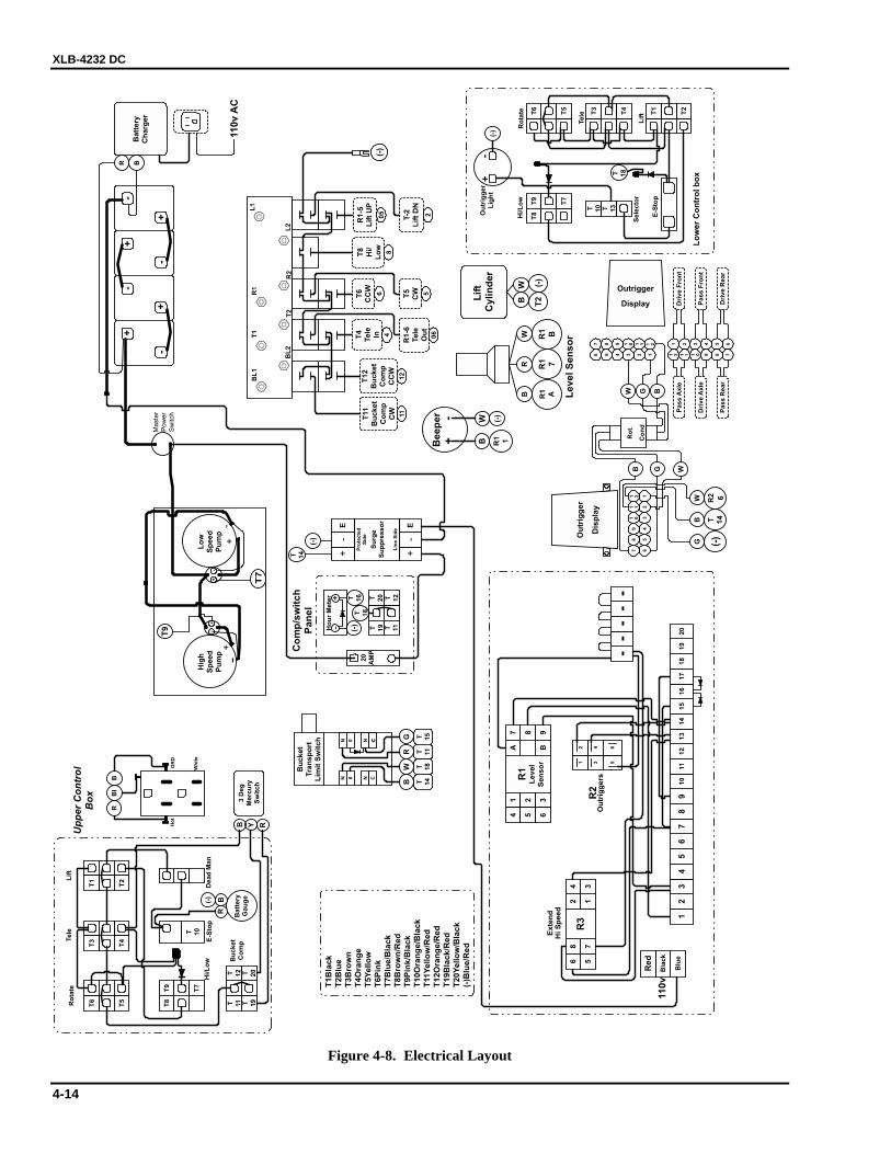
Figure 4-8. Electrical Layout
4 — MAINTENANCE
4-15
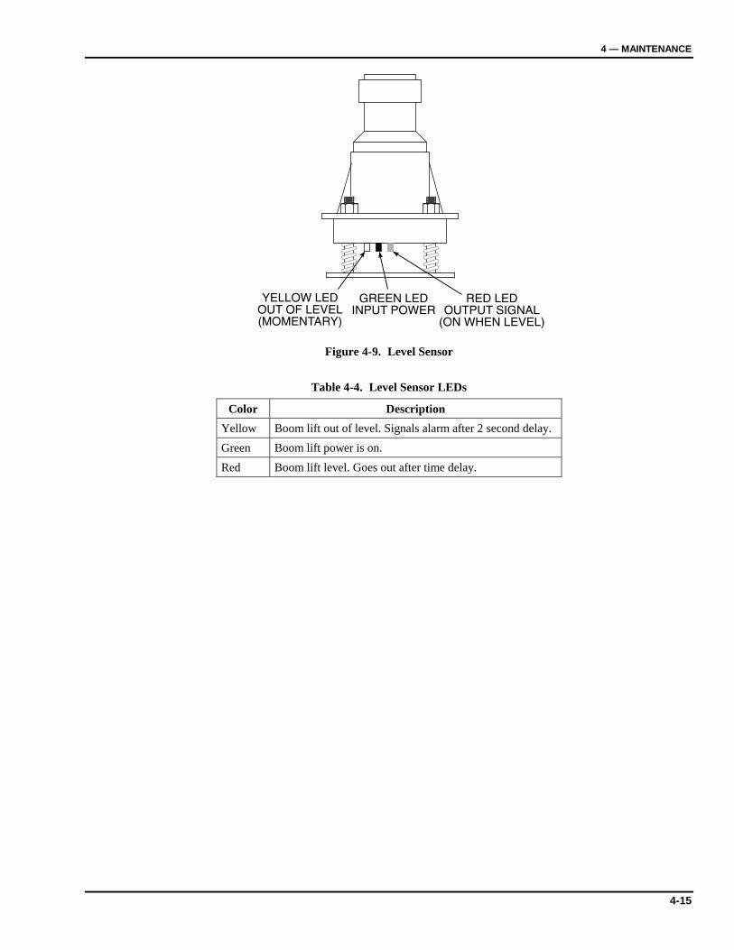
YELLOW LEDOUT OF LEVEL(MOMENTARY)
RED LEDOUTPUT SIGNAL
(ON WHEN LEVEL)
GREEN LEDINPUT POWER
Figure 4-9. Level Sensor
Table 4-4. Level Sensor LEDs
Color Description Yellow Boom lift out of level. Signals alarm after 2 second delay. Green Boom lift power is on. Red Boom lift level. Goes out after time delay.
XLB-4232 DC
4-16
1.6
GP
M
2.5
GP
M
BL2
BL1
L1
L2
R2
R1
T2
T1
V2
V1
C2
C1
65
5
4
3
7
8
2
1
1B
02
-05
-00
17
1D
ua
lP
um
pU
nit
2B
02
-04
-00
69
1M
an
ifo
ldC
om
bo
Va
lve
3B
02
-04
-00
09
1P
ilo
ted
Op
era
ted
Ch
ec
kV
alv
e
4B
02
-03
-00
20
1E
xte
nti
on
Cy
lin
de
r
5B
02
-03
-00
07
2M
as
ter/
Sla
ve
Cy
lin
de
r
6B
02
-04
-00
68
1D
ou
ble
Pil
ote
dO
pe
rate
dC
he
ck
Va
lve
7B
02
-06
-00
06
1R
ota
tio
nM
oto
r
8B
02
-03
-00
24
1L
ift
Cy
lin
de
r
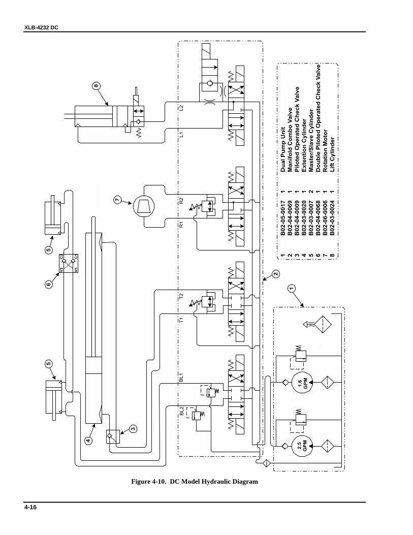
Figure 4-10. DC Model Hydraulic Diagram
4 — MAINTENANCE
4-17
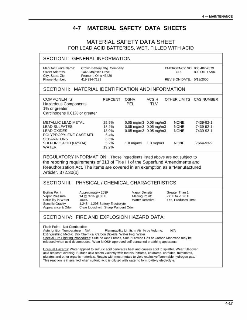
4-7 MATERIAL SAFETY DATA SHEETS
MATERIAL SAFETY DATA SHEET FOR LEAD ACID BATTERIES, WET, FILLED WITH ACID
SECTION I: GENERAL INFORMATION Manufacturer’s Name: Crown Battery Mfg. Company EMERGENCY NO: 800 487-2879 Street Address: 1445 Majestic Drive OR 800 OIL-TANK City, State, Zip Fremont, Ohio 43420 Phone Number: 419 334-7181 REVISION DATE: 5/18/2000
SECTION II: MATERIAL IDENTIFICATION AND INFORMATION
COMPONENTS PERCENT OSHA ACGIH OTHER LIMITS CAS NUMBER Hazardous Components PEL TLV 1% or greater Carcinogens 0.01% or greater
METALLIC LEAD METAL 25.5% 0.05 mg/m3 0.05 mg/m3 NONE 7439-92-1 LEAD SULFATES 18.2% 0.05 mg/m3 0.05 mg/m3 NONE 7439-92-1 LEAD OXIDES 18.0% 0.05 mg/m3 0.05 mg/m3 NONE 7439-92-1 POLYPROPYLENE CASE MTL 6.4% SEPARATORS 3.5% SULFURIC ACID (H2SO4) 5.2% 1.0 mg/m3 1.0 mg/m3 NONE 7664-93-9 WATER 19.2%
REGULATORY INFORMATION: Those ingredients listed above are not subject to the reporting requirements of 313 of Title III of the Superfund Amendments and Reauthorization Act. The items are covered in an exemption as a “Manufactured Article”. 372.30(b)
SECTION III: PHYSICAL / CHEMICAL CHARACTERISTICS
Boiling Point Approximately 203F Vapor Density: Greater Than 1 Vapor Pressure 14 @ 37% @ 80 F Melting Point: -36 F to -10.6 F Solubility in Water 100% Water Reactive: Yes, Produces Heat Specific Gravity 1.245 - 1.295 Battery Electrolyte Appearance & Odor Clear Liquid with Sharp Pungent Odor
SECTION IV: FIRE AND EXPLOSION HAZARD DATA:
Flash Point: Not Combustible Auto Ignition Temperature N/A Flammability Limits in Air % by Volume: N/A Extinguishing Media: Dry Chemical Carbon Dioxide, Water Fog, Water Special Fire Fighting Procedures: Sulfuric Acid Fumes, Sulfur Dioxide Gas or Carbon Monoxide may be released when acid decomposes. Wear NIOSH approved self-contained breathing apparatus. Unusual Hazards: Water applied to sulfuric acid generates heat and causes acid to splatter. Wear full-cover acid resistant clothing. Sulfuric acid reacts violently with metals, nitrates, chlorates, carbides, fulminates, picrates and other organic materials. Reacts with most metals to yield explosive/flammable hydrogen gas. This reaction is intensified when sulfuric acid is diluted with water to form battery electrolyte.
XLB-4232 DC
4-18
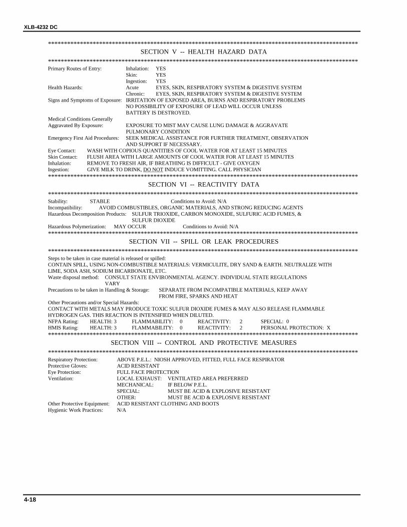
************************************************************************************************* SECTION V -- HEALTH HAZARD DATA
************************************************************************************************* Primary Routes of Entry: Inhalation: YES Skin: YES Ingestion: YES Health Hazards: Acute EYES, SKIN, RESPIRATORY SYSTEM & DIGESTIVE SYSTEM Chronic: EYES, SKIN, RESPIRATORY SYSTEM & DIGESTIVE SYSTEM Signs and Symptoms of Exposure: IRRITATION OF EXPOSED AREA, BURNS AND RESPIRATORY PROBLEMS NO POSSIBILITY OF EXPOSURE OF LEAD WILL OCCUR UNLESS BATTERY IS DESTROYED. Medical Conditions Generally Aggravated By Exposure: EXPOSURE TO MIST MAY CAUSE LUNG DAMAGE & AGGRAVATE PULMONARY CONDITION Emergency First Aid Procedures: SEEK MEDICAL ASSISTANCE FOR FURTHER TREATMENT, OBSERVATION AND SUPPORT IF NECESSARY. Eye Contact: WASH WITH COPIOUS QUANTITIES OF COOL WATER FOR AT LEAST 15 MINUTES Skin Contact: FLUSH AREA WITH LARGE AMOUNTS OF COOL WATER FOR AT LEAST 15 MINUTES Inhalation: REMOVE TO FRESH AIR, IF BREATHING IS DIFFICULT - GIVE OXYGEN Ingestion: GIVE MILK TO DRINK, DO NOT INDUCE VOMITTING. CALL PHYSICIAN *************************************************************************************************
SECTION VI -- REACTIVITY DATA ************************************************************************************************* Stability: STABLE Conditions to Avoid: N/A Incompatibility: AVOID COMBUSTIBLES, ORGANIC MATERIALS, AND STRONG REDUCING AGENTS Hazardous Decomposition Products: SULFUR TRIOXIDE, CARBON MONOXIDE, SULFURIC ACID FUMES, & SULFUR DIOXIDE Hazardous Polymerization: MAY OCCUR Conditions to Avoid: N/A *************************************************************************************************
SECTION VII -- SPILL OR LEAK PROCEDURES ************************************************************************************************* Steps to be taken in case material is released or spilled: CONTAIN SPILL, USING NON-COMBUSTIBLE MATERIALS: VERMICULITE, DRY SAND & EARTH. NEUTRALIZE WITH LIME, SODA ASH, SODIUM BICARBONATE, ETC. Waste disposal method: CONSULT STATE ENVIRONMENTAL AGENCY. INDIVIDUAL STATE REGULATIONS VARY Precautions to be taken in Handling & Storage: SEPARATE FROM INCOMPATIBLE MATERIALS, KEEP AWAY FROM FIRE, SPARKS AND HEAT Other Precautions and/or Special Hazards: CONTACT WITH METALS MAY PRODUCE TOXIC SULFUR DIOXIDE FUMES & MAY ALSO RELEASE FLAMMABLE HYDROGEN GAS. THIS REACTION IS INTENSIFIED WHEN DILUTED. NFPA Rating: HEALTH: 3 FLAMMABILITY: 0 REACTIVITY: 2 SPECIAL: 0 HMIS Rating: HEALTH: 3 FLAMMABILITY: 0 REACTIVITY: 2 PERSONAL PROTECTION: X *************************************************************************************************
SECTION VIII -- CONTROL AND PROTECTIVE MEASURES ************************************************************************************************* Respiratory Protection: ABOVE P.E.L.: NIOSH APPROVED, FITTED, FULL FACE RESPIRATOR Protective Gloves: ACID RESISTANT Eye Protection: FULL FACE PROTECTION Ventilation: LOCAL EXHAUST: VENTILATED AREA PREFERRED MECHANICAL: IF BELOW P.E.L. SPECIAL: MUST BE ACID & EXPLOSIVE RESISTANT OTHER: MUST BE ACID & EXPLOSIVE RESISTANT Other Protective Equipment: ACID RESISTANT CLOTHING AND BOOTS Hygienic Work Practices: N/A

4 — MAINTENANCE
4-19
MATERIAL SAFETY DATA SHEET
1-SITE SPECIFIC INFORMATION: AW-46 HYDRAULIC OIL
2-GENERAL INFORMATION TRADE NAME: AW-46 HYDRAULIC OILEMERGENCY TELEPHONE NUMBERS: (517) 849-2144CHEMICAL FAMILY: LUBRICATING OILCAS NUMBER: MIXTURE: ISSUE DATE 12/15/96HAZARDOUS INGREDIENTS:----------------------------------------------------------------------------
CONTAINS NO INGREDIENTS NOW KNOWN TO BE HAZARDOUS AS DEFINED IN OSHA 29 CFR1910.1000 AND OSHA 29 CFR 1910.1200.
----------------------------------------------------------------------------HEALTH HAZARD DATA THRESHHOLD LIMIT VALUE: 5mg/m3 AS OIL MIST 8 hr, TWAPRIMARY ROUTES OF ENTRY: INHALATION, SKIN ABRASION AND INGESTION.CARCINOGENIC: NOSYMPTOMS IF INGESTED, CONTACTED WITH SKIN, OR VAPOR INHALED: NO ADVERSEEFFECTS EXPECTED.EYES: FLUSH WITH WATER FOR 15 MINUTES SKIN: WASH THOROUGHLY WITH WARMSOAPY WATER.INGESTION: DO NOT INDUCE VOMITTING-SEEK MEDICAL ATTENTION.MEDICAL CONDITIONS AGGRAVATED BY EXPOSURE: NONE KNOWNAIR EXPOSURE LIMITS: P.E.L. NOT ESTABLISHED T.L.V.5mg/m3 OSHA 29 CFR1910.1000
HEALTH: 1FIRE: 1SPECIFIC: XREACTIVITY: 0----------------------------------------------------------------------------PHYSICAL DATA: BOILING POINT: 400+ DEG F. VAPOR PRESSURE (PSIA): N/ASPECIFIC GRAVITY (H20=1): 0.87 SOULUBILITY IN WATER: NEGLIGIBLEPH OF CONCENTRATE: N/AAPPEARANCE AND ODOR: PALE YELLOW, PETROLEUM ODOR----------------------------------------------------------------------------FIRE AND EXPLOSION HAZARD DATAFLASH POINT(METHOD USED): 425 DEG F.FLAMMABLE LIMITS: NOT DETERMINED LEL: N/AUEL: N/AEXTINGUISHING MEDIA: SAND, DRY CHEMICAL, FOAM, CO2. TREAT AS CLASS B FIRE.UNUSUAL FIRE AND EXPLOSION HAZARDS: NONE----------------------------------------------------------------------------REACTIVIYY DATA STABILITY: STABLE CONDITIONS TO AVOID: AVOID EXTREMESOF HEAT.INCOMPATIBILITY (MATERIALS TO AVOID): STRONG OXIDIZING MATERIALS.HAZARDOUS DECOMPOSITION PRODUCTS: INCOMPLETE COMBUSTION MAY CAUSE CARBONOXIDES.HAZARDOUS POLYMERIZATION: WILL NOT OCCUR.----------------------------------------------------------------------------SPILL OR LEAK PROCEDURES: STEPS TO BE TAKEN IN CASE MATERIAL IS RELEASED ORSPILLED. DIKE AND ABSORB ON INERT MATERIAL. FOLLOW ALL LOCAL, STATE, ANDFEDERAL REGULATIONS FOR DISPOSAL OF COLLECTED MATERIAL.----------------------------------------------------------------------------

XLB-4232 DC
4-20
PAGE 2
SPECIAL PROTECTION INFORMATION RESPIRATORY PROTECTION (SPECIFIC TYPE)NONE REQUIREDVENTILATION: NORMAL LOCAL EXHAUST: NORMALMECHANICAL EXHAUST (GENERAL) XPROTECTIVE GLOVES: OIL IMPERVIOUS GLOVES RECOMMENDEDEYE PROTECTION: SAFETY GLASSES RECOMMENDEDOTHER PROTECTIVE EQUIPMENT: NONE REQUIRED----------------------------------------------------------------------------
SPECIAL INSTRUCTIONS SPECIAL LABELLING INSTRUCTIONS: NOT REQUIREDSPECIAL PACKAGING RECOMMENDATIONS: NONEHANDLING AND STORAGE RECOMMENDATIONS: DO NOT CUT OR WELD ON EMPTYCONTAINERS, AVOID EXTREMES OF COLD OR HEAT. STORE IN CLEAN DRY AREA.
DISCLAIMER: THE INFORMATION CONTAINED HEREIN HAS BEEN COMPILED FROM SOURCESCONSIDERED TO BE DEPENDABLE AND IS ACCURATE TO THE BEST OF THE SELLERSKNOWLEDGE. THE SELLER MAKES NO WARRANTY WHATSOEVER, EXPRESSED, IMPLIED OR OFMERCHANTABILITY REGARDING THE ACCURACY OF SUCH DATA OR THE RESULTS TOBE OBTAINED FROM THE USE THEREOF.
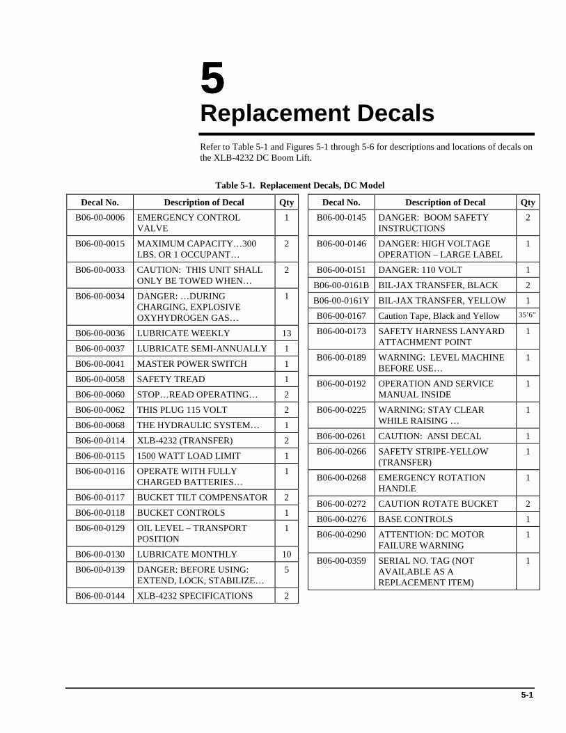
5-1
5555 Replacement Decals Refer to Table 5-1 and Figures 5-1 through 5-6 for descriptions and locations of decals on the XLB-4232 DC Boom Lift.
Table 5-1. Replacement Decals, DC Model
Decal No. Description of Decal QtyB06-00-0006 EMERGENCY CONTROL
VALVE 1
B06-00-0015 MAXIMUM CAPACITY…300 LBS. OR 1 OCCUPANT…
2
B06-00-0033 CAUTION: THIS UNIT SHALL ONLY BE TOWED WHEN…
2
B06-00-0034 DANGER: …DURING CHARGING, EXPLOSIVE OXYHYDROGEN GAS…
1
B06-00-0036 LUBRICATE WEEKLY 13
B06-00-0037 LUBRICATE SEMI-ANNUALLY 1
B06-00-0041 MASTER POWER SWITCH 1
B06-00-0058 SAFETY TREAD 1
B06-00-0060 STOP…READ OPERATING… 2
B06-00-0062 THIS PLUG 115 VOLT 2
B06-00-0068 THE HYDRAULIC SYSTEM… 1
B06-00-0114 XLB-4232 (TRANSFER) 2
B06-00-0115 1500 WATT LOAD LIMIT 1
B06-00-0116 OPERATE WITH FULLY CHARGED BATTERIES…
1
B06-00-0117 BUCKET TILT COMPENSATOR 2
B06-00-0118 BUCKET CONTROLS 1
B06-00-0129 OIL LEVEL – TRANSPORT POSITION
1
B06-00-0130 LUBRICATE MONTHLY 10
B06-00-0139 DANGER: BEFORE USING: EXTEND, LOCK, STABILIZE…
5
B06-00-0144 XLB-4232 SPECIFICATIONS 2
Decal No. Description of Decal QtyB06-00-0145 DANGER: BOOM SAFETY
INSTRUCTIONS 2
B06-00-0146 DANGER: HIGH VOLTAGE OPERATION – LARGE LABEL
1
B06-00-0151 DANGER: 110 VOLT 1
B06-00-0161B BIL-JAX TRANSFER, BLACK 2
B06-00-0161Y BIL-JAX TRANSFER, YELLOW 1
B06-00-0167 Caution Tape, Black and Yellow 35’6”
B06-00-0173 SAFETY HARNESS LANYARD ATTACHMENT POINT
1
B06-00-0189 WARNING: LEVEL MACHINE BEFORE USE…
1
B06-00-0192 OPERATION AND SERVICE MANUAL INSIDE
1
B06-00-0225 WARNING: STAY CLEAR WHILE RAISING …
1
B06-00-0261 CAUTION: ANSI DECAL 1
B06-00-0266 SAFETY STRIPE-YELLOW (TRANSFER)
1
B06-00-0268 EMERGENCY ROTATION HANDLE
1
B06-00-0272 CAUTION ROTATE BUCKET 2
B06-00-0276 BASE CONTROLS 1
B06-00-0290 ATTENTION: DC MOTOR FAILURE WARNING
1
B06-00-0359 SERIAL NO. TAG (NOT AVAILABLE AS A REPLACEMENT ITEM)
1
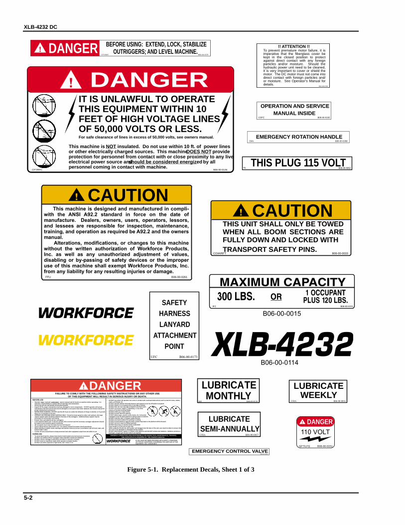
XLB-4232 DC
5-2
THIS PLUG 115 VOLTRIL B06-00-0062
LUBRICATEMONTHLY
B06-00-0130RIF
B06-00-0268OFA
EMERGENCY ROTATION HANDLE
COFC B06-00-0192
OPERATION AND SERVICEMANUAL INSIDE
DANGERFAILURE TO COMLY WITH THE FOLLOWING SAFETY INSTRUCTIONS OR ANY OTHER USE
OF THIS EQUIPMENT WILL RESULT IN SERIOUS INJURY OR DEATH.BEFORE USE• Operator must read and understand owners manual and all decals on machine before operating. It is
operators responsibility to comply with all warnings and instructions.• Survey the job site and identify all potential hazards.• Inspect lift for proper maintenance and any damaged or worn components. DO NOT operate until proper
maintenance has been performed and all damaged or worn parts have been replaced. See owners manual forproper maintenance procedures.
• NEVER TAKE CHANCES—DO NOT use this lift if you are under the influence of drugs or alcohol, or if you feeldizzy, ill, or unsteady in any way.
• OPERATE ON FIRM AND LEVEL SURFACE ONLY—if used on loose gravel or other soft surfaces, the largesquare support pads should be added to the base of the outriggers. Additional base support may benecessary on excessively soft footing.
• Extend, lock, and stabilize all four outriggers.• Level machine before use—if buzzer sounds, lift is not level and the necessary outrigger adjustment should
be made to level machine before continuing.• All occupants must wear full body harness and lanyard.• Check safety devices daily before use—see owners manual for proper check procedures.• When working on public roads, warnings and barriers must be set up in accordance with all local, state, and
federal traffic codes.• Cordon off area around base to keep personnel and other equipment away from unit while in use.
DURING USE• To avoid hand injuries, always keep hands inside basket area during boom movement.• DO NOT use without all four outriggers fully extended, locked and stabilized.• DO NOT release outriggers with boom extended or operator in basket.• DO NOT move or reposition trailer while operator occupies basket.• DO NOT use when exposed to high winds, rain, snow, or ice.
• DO NOT use where lift operator can come in contact with overhead obstructions such as electric wires, cables,ropes, overhangs, etc.
• DO NOT operate without full body harness and lanyard in use by all basket occupants.• DO NOT stand or sit on guard rails or top edge of basket.• DO NOT lean out over top edge of basket to perform work.• DO NOT use boxes, ladders, scaffolding, or any other
means to increase working height.• DO NOT climb up or down boom.• DO NOT exceed rated lift capacity.• DO NOT allow ropes, electric cords, hoses, etc. to become
entangled in the lift while platform is being raised or lowered.• DO NOT override, alter, or bypass safety devices.• DO NOT use boom rotation for pushing or pulling.• DO NOT exceed platform capacity when transferring loads to the platform while elevated.• DO NOT use as a crane for lifting materials.• DO NOT leave keys in machine while unattended.• Plug charger in at the end of each day.• When using the lift with the 110V power cord plugged into the base of the unit, care must be taken to ensure that
the cord is not damaged or entangled during rotation.• DO NOT allow flames, sparks, or embers near batteries and DO NOT smoke near batteries. Batteries produce a
hydrogen, oxygen gas mixture which can explode.
OWNERS & OPERATORS ARE RESPONSIBLE FOR INSPECTION, MAINTENANCE, TRAINING,AND OPERATION AS REQUIRED BY THE OWNERS MANUAL .
IF YOU HAVE NOT BEEN PROVIDED WITH SAFETY LITERATURE,OR FOR ANY QUESTIONS CONCERNING THE SAFE USE OF THISEQUIPMENT, CALL 419/445-9675.R
COIA/RFT B06-00-0033
THIS UNIT SHALL ONLY BE TOWEDWHEN ALL BOOM SECTIONS AREFULLY DOWN AND LOCKED WITHTRANSPORT SAFETY PINS.
CAUTION
This machine is NOT insulated. Do not use within 10 ft. of power linesor other electrically charged sources. This machineDOES NOT provideprotection for personnel from contact with or close proximity to any liveelectrical power source and by allshould be considered energizedpersonnel coming in contact with machine.
IT IS UNLAWFUL TO OPERATETHIS EQUIPMENT WITHIN 10FEET OF HIGH VOLTAGE LINESOF 50,000 VOLTS OR LESS.For safe clearance of lines in excess of 50,000 volts, see owners manual.
CFT/RFC B06-00-0146
DANGER B06-00-0290
!! ATTENTION !!To prevent premature motor failure, it isimperative that the fiberglass cover bekept in the closed position to protectagainst direct contact with any foreignparticles and/or moisture. Should thehydraulic power unit need to be cleaned,it is very important to cover or shield themotor. The DC motor must not come intodirect contact with foreign particles and/or moisture. See Operator’s Manual fordetails.
B06-00-0261FFU
This machine is designed and manufactured in compli-with the ANSI A92.2 standard in force on the date ofmanufacture. Dealers, owners, users, operators, lessors,and lessees are responsible for inspection, maintenance,training, and operation as required be A92.2 and the ownersm
Alterations, modifications, or changes to this machinewithout the written authorization of Workforce Products,Inc. as well as any unauthorized adjustment of values,disabling or by-passing of safety devices or the improperuse of this machine shall exempt Workforce Products, Inc.from any liability for any resulting injuries or damage.
CAUTION
anual.
BEFORE USING: EXTEND, LOCK, STABILIZEOUTRIGGERS; AND LEVEL MACHINE.DANGER
CFT/RFC B06-00-0139
EMERGENCY CONTROL VALVEB06-00-0006
LUBRICATESEMI-ANNUALLY
COIA B06-00-0037
LUBRICATEWEEKLY
COIA B06-00-0036
SAFETYHARNESSLANYARD
ATTACHMENTPOINT
B06-00-0173UFC
B06-00-0151GFT/LFG
DANGER110 VOLT
B06-00-0015
B06-00-0114
35
XLB-4232
Figure 5-1. Replacement Decals, Sheet 1 of 3
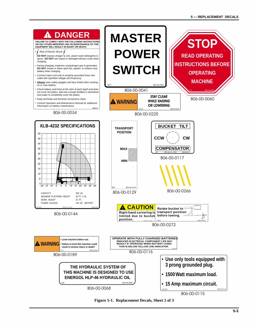
5 — REPLACEMENT DECALS
5-3
DANGER
• Risk of Electric Shock
DO NOT expose charger to rain, power wash detergents orspray - DO NOT use frayed or damaged electric cords whencharging.
• During charging, explosive oxyhydrogen gas is generated.DO NOT smoke or allow open fire, sparks, or embers nearbattery when charging.
• Connect input cord only to properly grounded three wireoutlet with specified voltage and frequency.
• Always wear safety goggles and face shield when workingon or near battery.
• Check battery acid level at the start of each day. If acid doesnot cover the plates, add only enough distilled or demineral-ized water to completely cover the plates.
• Keep terminals and terminal connections clean.
• Consult Operation and Maintenance Manual for additionalinformation on battery maintenance.
FAILURE TO COMPLY WITH THE FOLLOWING INSTRUCTIONSOR ANY OTHER IMPROPER USE OR MAINTENANCE OF THISEQUIPMENT WILL RESULT IN INJURY OR DEATH.
RIR/OFG
B06-00-0034
B06-00-0144
B06-00-0117
RIL B06-00-0060
STOPREAD OPERATING
INSTRUCTIONS BEFORE
OPERATING
MACHINE
MAX
MIN
TRANSPORTPOSITION
RIF B06-00-0129
B06-00-0129
B06-00-0272
LFC B06-00-0189
B06-00-0189
WARNING• Level machine before use.
• Failure to level this machine couldresult in serious injury or death!
THE HYDRAULIC SYSTEM OFTHIS MACHINE IS DESIGNED TO USEENERGOL HLP-46 HYDRAULIC OIL
OII B06-00-0068
B06-00-0068
B06-00-0060
OPERATE WITH FULLY CHARGED BATTERIESREDUCED ELECTRICAL COMPONENT LIFE MAYRESULT IF OPERATED WHEN BATTERY CONDI-
TION IS BELOW YELLOW LINE INDICATOR.B06-00-0116
B06-00-0116
MASTERPOWERSWITCH
RFT B06-00-0041
B06-00-0041
CCFO B06-00-0225
WARNINGSTAY CLEAR
WHILE RAISING
OR LOWERING
B06-00-0225
B06-00-0115
B06-00-0115AIF/RFC
• Use only tools equipped with3 prong grounded plug.
• 1500 Watt maximum load.
• 15 Amp maximum circuit.
CCW . CW
COMPENSATOR
BUCKET TILT
AIF B06-00-0117© Bil-Jax, Inc. 2004
CFT/OFG
XLB-4232 SPECIFICATIONS
CAPACITY 300 LB.MAXIMUM PLATFORM HEIGHT 35 FT. 5 IN.WORK HEIGHT 42 FT.POWER SOURCE 24V DC BATTERY
B06-00-0144© Bil-Jax, Inc. 2004
Right-hand cornering islimited due to bucketposition.
CAUTION Rotate bucket totransport positionbefore towing.
COFG B06-00-0272© Bil-Jax, Inc. 2004
B06-00-0266
Figure 5-1. Replacement Decals, Sheet 2 of 3
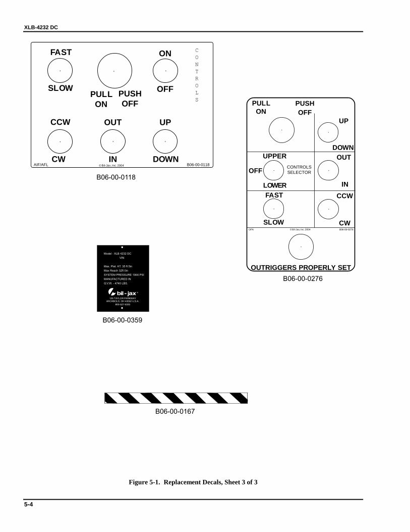
XLB-4232 DC
5-4
B06-00-0118
B06-00-0276
B06-00-0167
CONTROLS
B06-00-0118AIF/AFL
...
.. .
FAST ON
SLOW OFF
CW IN DOWN
PULLON
CCW OUT UP
PUSHOFF
© Bil-Jax, Inc. 2004
UP
OUT
CCW
UPPER
LOWER
CW
.
.
SLOW
FAST
DOWN
.
.
.
OFFCONTROLSSELECTOR
IN
PULLON
PUSHOFF
.
.
B06-00-0276OFA
OUTRIGGERS PROPERLY SET
© Bil-Jax, Inc. 2004
B06-00-0359
Model - XLB 4232 DC
VIN
Max. Plat. HT. 35 ft 5in
Max Reach 32ft 0in
SYSTEM PRESSURE 1900 PSI
MANUFACTURED IN
G.V.W. - 4740 LBS.
Figure 5-1. Replacement Decals, Sheet 3 of 3

5 — REPLACEMENT DECALS
5-5
B06-0
0-0
145
B06-0
0-0
116
B06-0
0-0
115
B06-0
0-0
118
B06-0
0-0
117
B06-0
0-0
144
B06-0
0-0
173
B06-0
0-0
015
B06-0
0-0
192
B06-0
0-0
060
(OU
TS
IDE
OF
DO
OR
)
B06-0
0-0
139
B06-0
0-0
130
B06-0
0-0
037
B06-0
0-0
139
B06-0
0-0
130
(WO
RM
GE
AR
)
B06-0
0-0
161Y
B06-0
0-0
139
Figure 5-2. Decal Locations, Top View
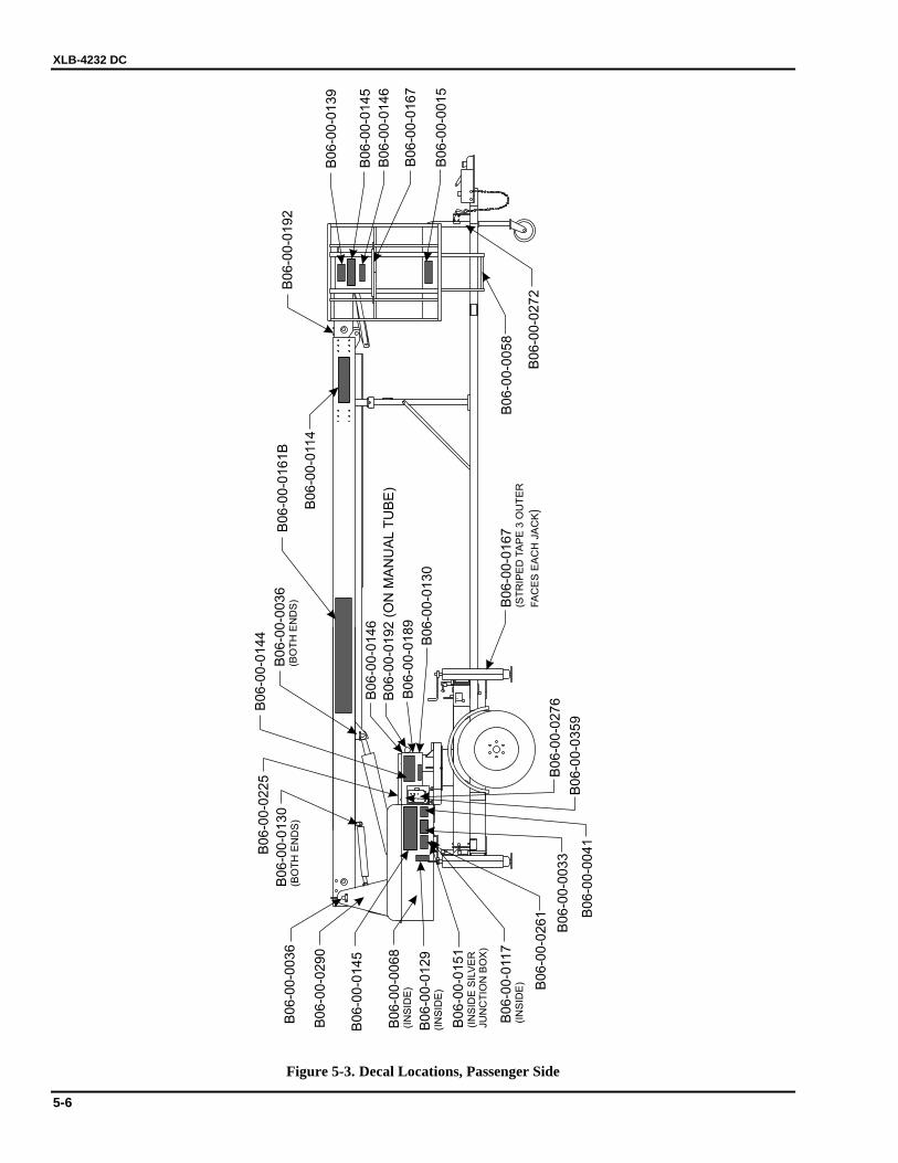
XLB-4232 DC
5-6
B0
6-0
0-0
22
5
B0
6-0
0-0
13
0(B
OT
HE
ND
S)
B0
6-0
0-0
27
2
B0
6-0
0-0
05
8
B0
6-0
0-0
13
0
B0
6-0
0-0
18
9
B0
6-0
0-0
14
6
B0
6-0
0-0
19
2(O
NM
AN
UA
LT
UB
E)
B0
6-0
0-0
16
7
)(S
TR
IPE
DTA
PE
3O
UT
ER
FA
CE
SE
AC
HJA
CK
B0
6-0
0-0
27
6
B0
6-0
0-0
35
9B
06
-00
-00
41
B0
6-0
0-0
03
3
B0
6-0
0-0
26
1
B0
6-0
0-0
11
7(I
NS
IDE
)
B0
6-0
0-0
15
1(I
NS
IDE
SIL
VE
RJU
NC
TIO
NB
OX
)
B0
6-0
0-0
12
9(I
NS
IDE
)
B0
6-0
0-0
06
8(I
NS
IDE
)
B0
6-0
0-0
14
5
B0
6-0
0-0
29
0
B0
6-0
0-0
03
6
B0
6-0
0-0
14
4
B0
6-0
0-0
03
6(B
OT
HE
ND
S)
B0
6-0
0-0
16
1B
B0
6-0
0-0
11
4
B0
6-0
0-0
19
2
B0
6-0
0-0
13
9
B0
6-0
0-0
14
5
B0
6-0
0-0
14
6
B0
6-0
0-0
16
7
B0
6-0
0-0
01
5
Figure 5-3. Decal Locations, Passenger Side
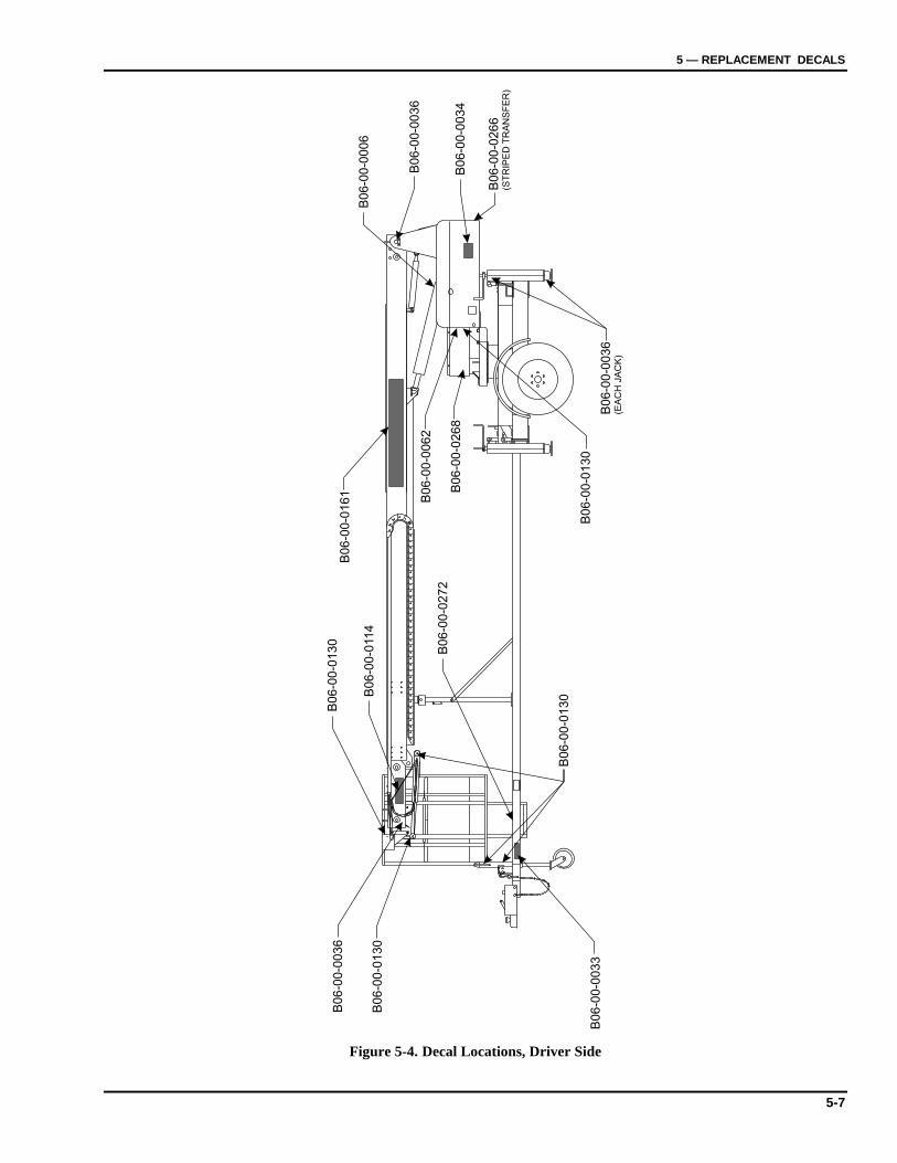
5 — REPLACEMENT DECALS
5-7
B06-0
0-0
006
B06-0
0-0
036
B06-0
0-0
034
B06-0
0-0
266
(ST
RIP
ED
TR
AN
SF
ER
)
B0
6-0
0-0
03
6(E
AC
HJA
CK
)
B0
6-0
0-0
13
0
B06-0
0-0
268
B06-0
0-0
062
B06-0
0-0
033
B06-0
0-0
130
B06-0
0-0
036
B0
6-0
0-0
16
1B
06-0
0-0
130
B06-0
0-0
114
B06-0
0-0
272
B0
6-0
0-0
13
0
Figure 5-4. Decal Locations, Driver Side

XLB-4232 DC
5-8

6-1
6666 Parts List
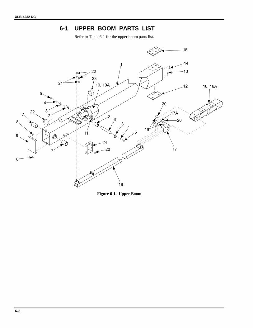
XLB-4232 DC
6-2
6-1 UPPER BOOM PARTS LIST Refer to Table 6-1 for the upper boom parts list.
2
15
14
13
12
26
1
16, 16A
3
22
3
4
21
4
5
18
17
5
7
7
19
8 20
20
17A
20
24
8
11
10, 10A
9
22
23
Figure 6-1. Upper Boom
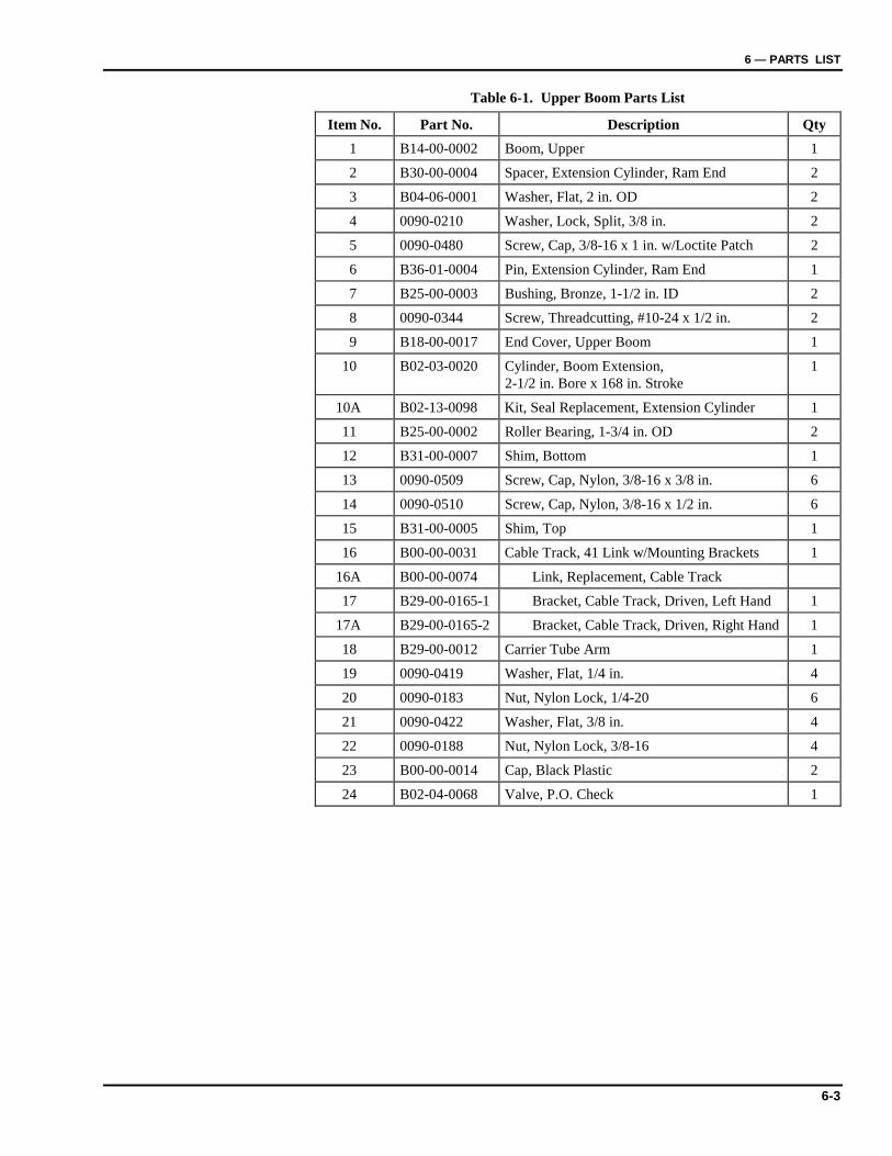
6 — PARTS LIST
6-3
Table 6-1. Upper Boom Parts List
Item No. Part No. Description Qty 1 B14-00-0002 Boom, Upper 1
2 B30-00-0004 Spacer, Extension Cylinder, Ram End 2
3 B04-06-0001 Washer, Flat, 2 in. OD 2
4 0090-0210 Washer, Lock, Split, 3/8 in. 2
5 0090-0480 Screw, Cap, 3/8-16 x 1 in. w/Loctite Patch 2
6 B36-01-0004 Pin, Extension Cylinder, Ram End 1
7 B25-00-0003 Bushing, Bronze, 1-1/2 in. ID 2
8 0090-0344 Screw, Threadcutting, #10-24 x 1/2 in. 2
9 B18-00-0017 End Cover, Upper Boom 1
10 B02-03-0020 Cylinder, Boom Extension, 2-1/2 in. Bore x 168 in. Stroke
1
10A B02-13-0098 Kit, Seal Replacement, Extension Cylinder 1
11 B25-00-0002 Roller Bearing, 1-3/4 in. OD 2
12 B31-00-0007 Shim, Bottom 1
13 0090-0509 Screw, Cap, Nylon, 3/8-16 x 3/8 in. 6
14 0090-0510 Screw, Cap, Nylon, 3/8-16 x 1/2 in. 6
15 B31-00-0005 Shim, Top 1
16 B00-00-0031 Cable Track, 41 Link w/Mounting Brackets 1
16A B00-00-0074 Link, Replacement, Cable Track
17 B29-00-0165-1 Bracket, Cable Track, Driven, Left Hand 1
17A B29-00-0165-2 Bracket, Cable Track, Driven, Right Hand 1
18 B29-00-0012 Carrier Tube Arm 1
19 0090-0419 Washer, Flat, 1/4 in. 4
20 0090-0183 Nut, Nylon Lock, 1/4-20 6
21 0090-0422 Washer, Flat, 3/8 in. 4
22 0090-0188 Nut, Nylon Lock, 3/8-16 4
23 B00-00-0014 Cap, Black Plastic 2
24 B02-04-0068 Valve, P.O. Check 1
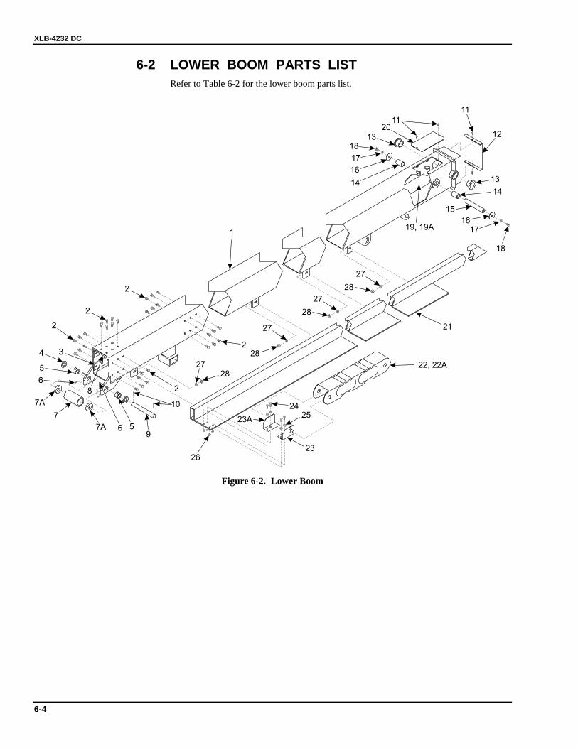
XLB-4232 DC
6-4
6-2 LOWER BOOM PARTS LIST Refer to Table 6-2 for the lower boom parts list.
2
2
2
2
2
34
5
5
8
9
6
7A
7
7A 6
1
11
11
12
13
13
1414
15
16
16
17
17
18
19, 19A
20
21
24
23
23A25
26
27
27
27
27
28
28
28
28
22, 22A
18
10
Figure 6-2. Lower Boom
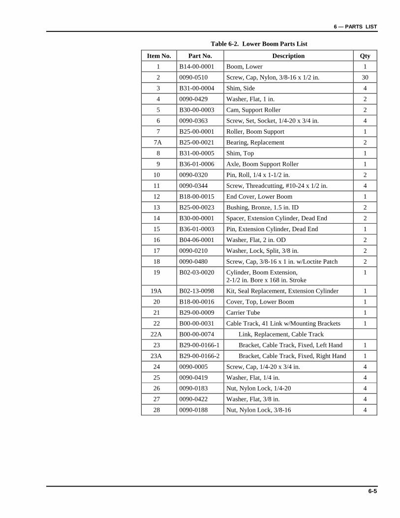
6 — PARTS LIST
6-5
Table 6-2. Lower Boom Parts List
Item No. Part No. Description Qty 1 B14-00-0001 Boom, Lower 1
2 0090-0510 Screw, Cap, Nylon, 3/8-16 x 1/2 in. 30
3 B31-00-0004 Shim, Side 4
4 0090-0429 Washer, Flat, 1 in. 2
5 B30-00-0003 Cam, Support Roller 2
6 0090-0363 Screw, Set, Socket, 1/4-20 x 3/4 in. 4
7 B25-00-0001 Roller, Boom Support 1
7A B25-00-0021 Bearing, Replacement 2
8 B31-00-0005 Shim, Top 1
9 B36-01-0006 Axle, Boom Support Roller 1
10 0090-0320 Pin, Roll, 1/4 x 1-1/2 in. 2
11 0090-0344 Screw, Threadcutting, #10-24 x 1/2 in. 4
12 B18-00-0015 End Cover, Lower Boom 1
13 B25-00-0023 Bushing, Bronze, 1.5 in. ID 2
14 B30-00-0001 Spacer, Extension Cylinder, Dead End 2
15 B36-01-0003 Pin, Extension Cylinder, Dead End 1
16 B04-06-0001 Washer, Flat, 2 in. OD 2
17 0090-0210 Washer, Lock, Split, 3/8 in. 2
18 0090-0480 Screw, Cap, 3/8-16 x 1 in. w/Loctite Patch 2
19 B02-03-0020 Cylinder, Boom Extension, 2-1/2 in. Bore x 168 in. Stroke
1
19A B02-13-0098 Kit, Seal Replacement, Extension Cylinder 1
20 B18-00-0016 Cover, Top, Lower Boom 1
21 B29-00-0009 Carrier Tube 1
22 B00-00-0031 Cable Track, 41 Link w/Mounting Brackets 1
22A B00-00-0074 Link, Replacement, Cable Track
23 B29-00-0166-1 Bracket, Cable Track, Fixed, Left Hand 1
23A B29-00-0166-2 Bracket, Cable Track, Fixed, Right Hand 1
24 0090-0005 Screw, Cap, 1/4-20 x 3/4 in. 4
25 0090-0419 Washer, Flat, 1/4 in. 4 26 0090-0183 Nut, Nylon Lock, 1/4-20 4
27 0090-0422 Washer, Flat, 3/8 in. 4
28 0090-0188 Nut, Nylon Lock, 3/8-16 4
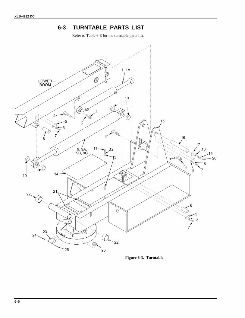
XLB-4232 DC
6-6
6-3 TURNTABLE PARTS LIST Refer to Table 6-3 for the turntable parts list.
10
10
2122
22
2625
2324
7
5
8
6
3
74
5
6
16
15
17
1819
20
14
12
13
2
2
3
78
9, 9A,9B, 9C
11
4
5
6
1, 1A
LOWERBOOM
Figure 6-3. Turntable
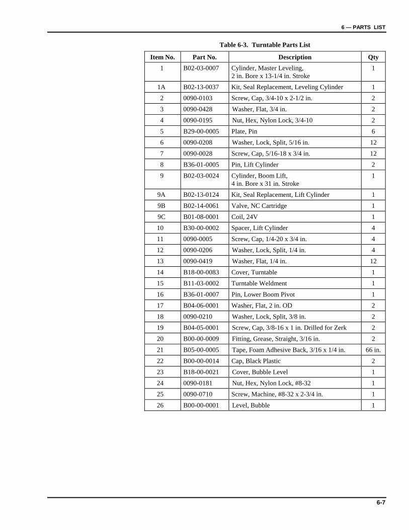
6 — PARTS LIST
6-7
Table 6-3. Turntable Parts List
Item No. Part No. Description Qty 1 B02-03-0007 Cylinder, Master Leveling,
2 in. Bore x 13-1/4 in. Stroke 1
1A B02-13-0037 Kit, Seal Replacement, Leveling Cylinder 1
2 0090-0103 Screw, Cap, 3/4-10 x 2-1/2 in. 2
3 0090-0428 Washer, Flat, 3/4 in. 2
4 0090-0195 Nut, Hex, Nylon Lock, 3/4-10 2
5 B29-00-0005 Plate, Pin 6
6 0090-0208 Washer, Lock, Split, 5/16 in. 12
7 0090-0028 Screw, Cap, 5/16-18 x 3/4 in. 12
8 B36-01-0005 Pin, Lift Cylinder 2
9 B02-03-0024 Cylinder, Boom Lift, 4 in. Bore x 31 in. Stroke
1
9A B02-13-0124 Kit, Seal Replacement, Lift Cylinder 1
9B B02-14-0061 Valve, NC Cartridge 1
9C B01-08-0001 Coil, 24V 1
10 B30-00-0002 Spacer, Lift Cylinder 4
11 0090-0005 Screw, Cap, 1/4-20 x 3/4 in. 4
12 0090-0206 Washer, Lock, Split, 1/4 in. 4
13 0090-0419 Washer, Flat, 1/4 in. 12
14 B18-00-0083 Cover, Turntable 1
15 B11-03-0002 Turntable Weldment 1
16 B36-01-0007 Pin, Lower Boom Pivot 1
17 B04-06-0001 Washer, Flat, 2 in. OD 2
18 0090-0210 Washer, Lock, Split, 3/8 in. 2
19 B04-05-0001 Screw, Cap, 3/8-16 x 1 in. Drilled for Zerk 2
20 B00-00-0009 Fitting, Grease, Straight, 3/16 in. 2
21 B05-00-0005 Tape, Foam Adhesive Back, 3/16 x 1/4 in. 66 in.
22 B00-00-0014 Cap, Black Plastic 2
23 B18-00-0021 Cover, Bubble Level 1
24 0090-0181 Nut, Hex, Nylon Lock, #8-32 1
25 0090-0710 Screw, Machine, #8-32 x 2-3/4 in. 1
26 B00-00-0001 Level, Bubble 1
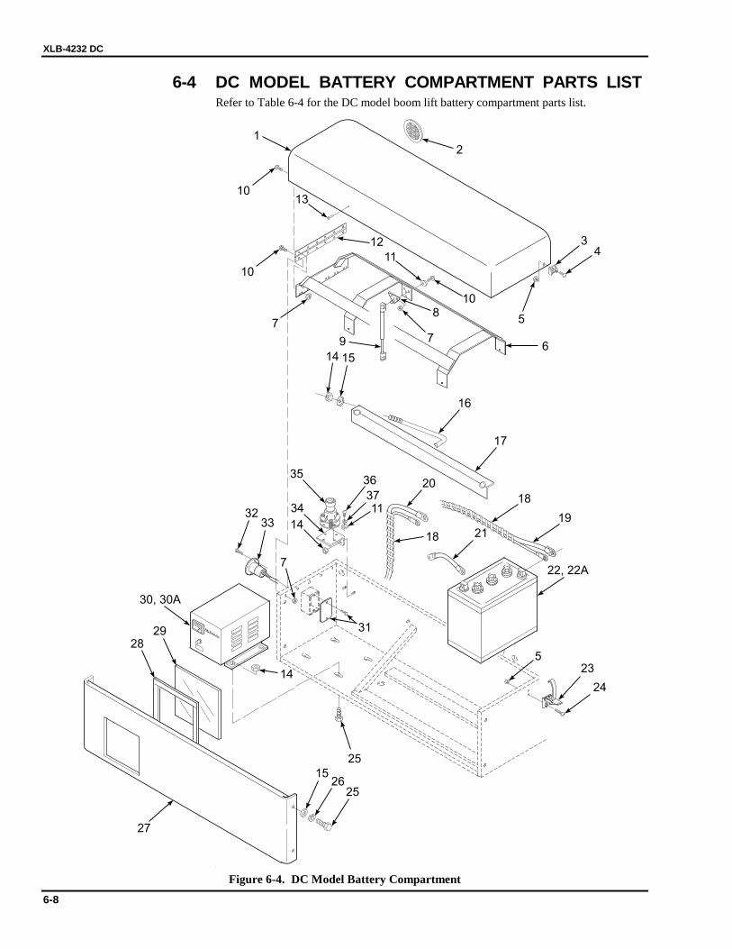
XLB-4232 DC
6-8
6-4 DC MODEL BATTERY COMPARTMENT PARTS LIST Refer to Table 6-4 for the DC model boom lift battery compartment parts list.
10
1
2
43
5
67
7
810
11
13
12
10
7
9
14 15
16
17
18
18
19
20
21
22, 22A
23
24
25
14
31
1526
25
27
2829
30, 30A
3233
35
34
14
36
37
5
11
c
Figure 6-4. DC Model Battery Compartment
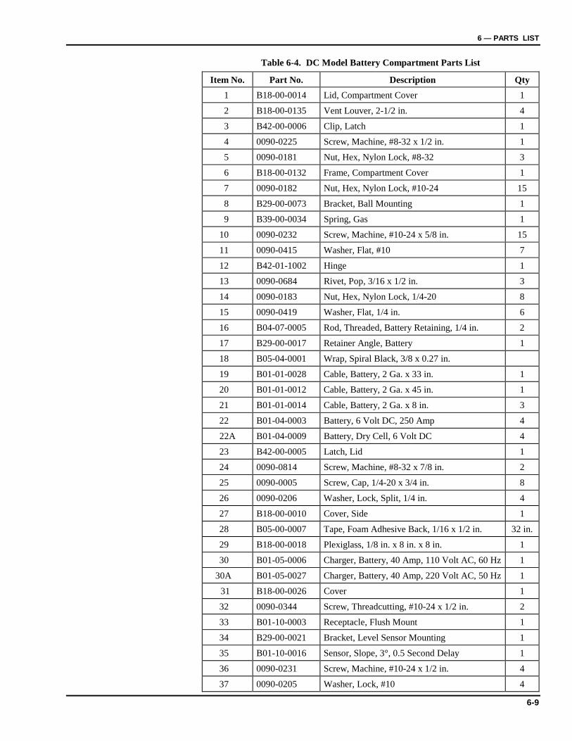
6 — PARTS LIST
6-9
Table 6-4. DC Model Battery Compartment Parts List
Item No. Part No. Description Qty 1 B18-00-0014 Lid, Compartment Cover 1
2 B18-00-0135 Vent Louver, 2-1/2 in. 4
3 B42-00-0006 Clip, Latch 1
4 0090-0225 Screw, Machine, #8-32 x 1/2 in. 1
5 0090-0181 Nut, Hex, Nylon Lock, #8-32 3
6 B18-00-0132 Frame, Compartment Cover 1
7 0090-0182 Nut, Hex, Nylon Lock, #10-24 15
8 B29-00-0073 Bracket, Ball Mounting 1
9 B39-00-0034 Spring, Gas 1
10 0090-0232 Screw, Machine, #10-24 x 5/8 in. 15
11 0090-0415 Washer, Flat, #10 7
12 B42-01-1002 Hinge 1
13 0090-0684 Rivet, Pop, 3/16 x 1/2 in. 3
14 0090-0183 Nut, Hex, Nylon Lock, 1/4-20 8
15 0090-0419 Washer, Flat, 1/4 in. 6
16 B04-07-0005 Rod, Threaded, Battery Retaining, 1/4 in. 2
17 B29-00-0017 Retainer Angle, Battery 1
18 B05-04-0001 Wrap, Spiral Black, 3/8 x 0.27 in.
19 B01-01-0028 Cable, Battery, 2 Ga. x 33 in. 1
20 B01-01-0012 Cable, Battery, 2 Ga. x 45 in. 1
21 B01-01-0014 Cable, Battery, 2 Ga. x 8 in. 3
22 B01-04-0003 Battery, 6 Volt DC, 250 Amp 4
22A B01-04-0009 Battery, Dry Cell, 6 Volt DC 4
23 B42-00-0005 Latch, Lid 1
24 0090-0814 Screw, Machine, #8-32 x 7/8 in. 2
25 0090-0005 Screw, Cap, 1/4-20 x 3/4 in. 8
26 0090-0206 Washer, Lock, Split, 1/4 in. 4
27 B18-00-0010 Cover, Side 1
28 B05-00-0007 Tape, Foam Adhesive Back, 1/16 x 1/2 in. 32 in.
29 B18-00-0018 Plexiglass, 1/8 in. x 8 in. x 8 in. 1
30 B01-05-0006 Charger, Battery, 40 Amp, 110 Volt AC, 60 Hz 1
30A B01-05-0027 Charger, Battery, 40 Amp, 220 Volt AC, 50 Hz 1
31 B18-00-0026 Cover 1
32 0090-0344 Screw, Threadcutting, #10-24 x 1/2 in. 2
33 B01-10-0003 Receptacle, Flush Mount 1
34 B29-00-0021 Bracket, Level Sensor Mounting 1
35 B01-10-0016 Sensor, Slope, 3°, 0.5 Second Delay 1
36 0090-0231 Screw, Machine, #10-24 x 1/2 in. 4
37 0090-0205 Washer, Lock, #10 4

XLB-4232 DC
6-10
6-5 DC MODEL POWER COMPARTMENT PARTS LIST Refer to Table 6-5 for the DC model power compartment parts list.
1
2 3
4
5 3
3
10
54
55
56
60
8
67
6
9
13 1211
14
15
18
16
17
19
5758
59
6162
3
63 64
61
2325
26
30, 31
21
27
28
20
29
32
33
3435
20
36
3841
45
40
39
28
28
41
44
46
434220
20
52
37
22
22
6
24
53
50
51
21
47
21
48
48
49 22
11
Figure 6-5. DC Model Power Compartment
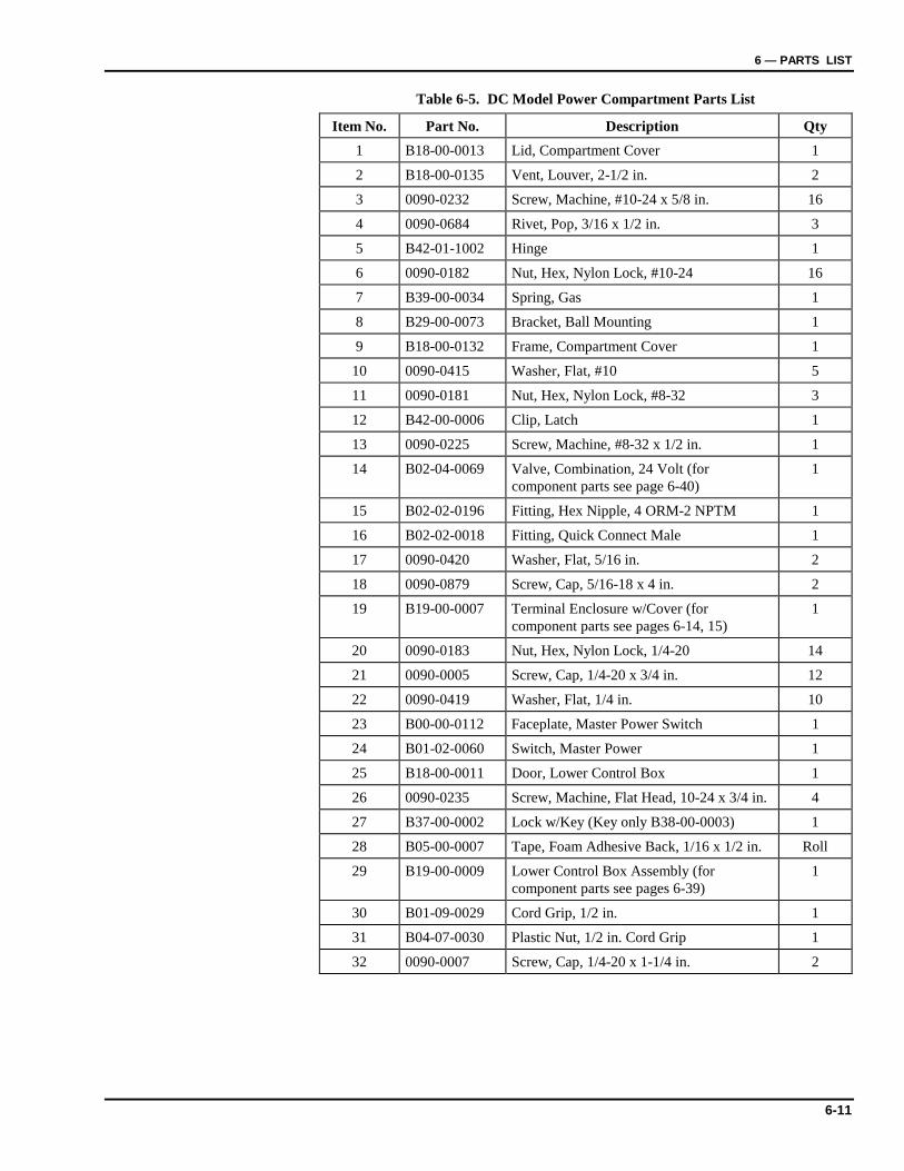
6 — PARTS LIST
6-11
Table 6-5. DC Model Power Compartment Parts List
Item No. Part No. Description Qty 1 B18-00-0013 Lid, Compartment Cover 1
2 B18-00-0135 Vent, Louver, 2-1/2 in. 2
3 0090-0232 Screw, Machine, #10-24 x 5/8 in. 16
4 0090-0684 Rivet, Pop, 3/16 x 1/2 in. 3
5 B42-01-1002 Hinge 1
6 0090-0182 Nut, Hex, Nylon Lock, #10-24 16
7 B39-00-0034 Spring, Gas 1
8 B29-00-0073 Bracket, Ball Mounting 1
9 B18-00-0132 Frame, Compartment Cover 1
10 0090-0415 Washer, Flat, #10 5
11 0090-0181 Nut, Hex, Nylon Lock, #8-32 3
12 B42-00-0006 Clip, Latch 1
13 0090-0225 Screw, Machine, #8-32 x 1/2 in. 1
14 B02-04-0069 Valve, Combination, 24 Volt (for component parts see page 6-40)
1
15 B02-02-0196 Fitting, Hex Nipple, 4 ORM-2 NPTM 1
16 B02-02-0018 Fitting, Quick Connect Male 1
17 0090-0420 Washer, Flat, 5/16 in. 2
18 0090-0879 Screw, Cap, 5/16-18 x 4 in. 2
19 B19-00-0007 Terminal Enclosure w/Cover (for component parts see pages 6-14, 15)
1
20 0090-0183 Nut, Hex, Nylon Lock, 1/4-20 14
21 0090-0005 Screw, Cap, 1/4-20 x 3/4 in. 12
22 0090-0419 Washer, Flat, 1/4 in. 10
23 B00-00-0112 Faceplate, Master Power Switch 1
24 B01-02-0060 Switch, Master Power 1
25 B18-00-0011 Door, Lower Control Box 1
26 0090-0235 Screw, Machine, Flat Head, 10-24 x 3/4 in. 4
27 B37-00-0002 Lock w/Key (Key only B38-00-0003) 1
28 B05-00-0007 Tape, Foam Adhesive Back, 1/16 x 1/2 in. Roll
29 B19-00-0009 Lower Control Box Assembly (for component parts see pages 6-39)
1
30 B01-09-0029 Cord Grip, 1/2 in. 1
31 B04-07-0030 Plastic Nut, 1/2 in. Cord Grip 1
32 0090-0007 Screw, Cap, 1/4-20 x 1-1/4 in. 2
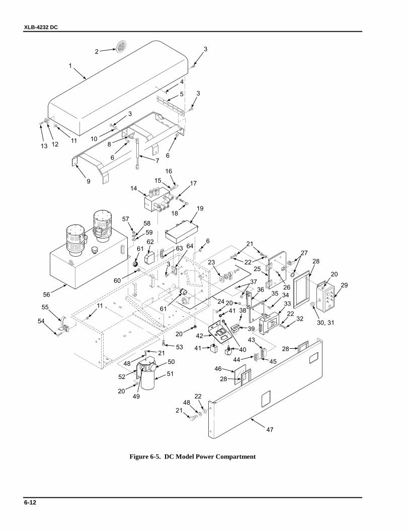
XLB-4232 DC
6-12
1
2 3
4
5 3
3
10
54
55
56
60
8
67
6
9
13 1211
14
15
18
16
17
19
5758
59
6162
3
63 64
61
2325
26
30, 31
21
27
28
20
29
32
33
3435
20
36
3841
45
40
39
28
28
41
44
46
434220
20
52
37
22
22
6
24
53
50
51
21
47
21
48
48
49 22
11
Figure 6-5. DC Model Power Compartment
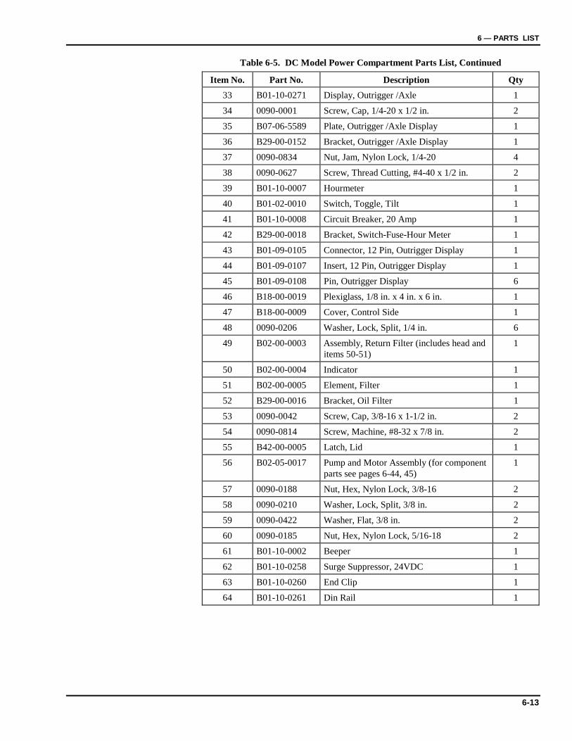
6 — PARTS LIST
6-13
Table 6-5. DC Model Power Compartment Parts List, Continued
Item No. Part No. Description Qty 33 B01-10-0271 Display, Outrigger /Axle 1
34 0090-0001 Screw, Cap, 1/4-20 x 1/2 in. 2
35 B07-06-5589 Plate, Outrigger /Axle Display 1
36 B29-00-0152 Bracket, Outrigger /Axle Display 1
37 0090-0834 Nut, Jam, Nylon Lock, 1/4-20 4
38 0090-0627 Screw, Thread Cutting, #4-40 x 1/2 in. 2
39 B01-10-0007 Hourmeter 1
40 B01-02-0010 Switch, Toggle, Tilt 1
41 B01-10-0008 Circuit Breaker, 20 Amp 1
42 B29-00-0018 Bracket, Switch-Fuse-Hour Meter 1
43 B01-09-0105 Connector, 12 Pin, Outrigger Display 1
44 B01-09-0107 Insert, 12 Pin, Outrigger Display 1
45 B01-09-0108 Pin, Outrigger Display 6
46 B18-00-0019 Plexiglass, 1/8 in. x 4 in. x 6 in. 1
47 B18-00-0009 Cover, Control Side 1
48 0090-0206 Washer, Lock, Split, 1/4 in. 6
49 B02-00-0003 Assembly, Return Filter (includes head and items 50-51)
1
50 B02-00-0004 Indicator 1
51 B02-00-0005 Element, Filter 1
52 B29-00-0016 Bracket, Oil Filter 1
53 0090-0042 Screw, Cap, 3/8-16 x 1-1/2 in. 2
54 0090-0814 Screw, Machine, #8-32 x 7/8 in. 2
55 B42-00-0005 Latch, Lid 1
56 B02-05-0017 Pump and Motor Assembly (for component parts see pages 6-44, 45)
1
57 0090-0188 Nut, Hex, Nylon Lock, 3/8-16 2
58 0090-0210 Washer, Lock, Split, 3/8 in. 2
59 0090-0422 Washer, Flat, 3/8 in. 2
60 0090-0185 Nut, Hex, Nylon Lock, 5/16-18 2
61 B01-10-0002 Beeper 1
62 B01-10-0258 Surge Suppressor, 24VDC 1
63 B01-10-0260 End Clip 1
64 B01-10-0261 Din Rail 1
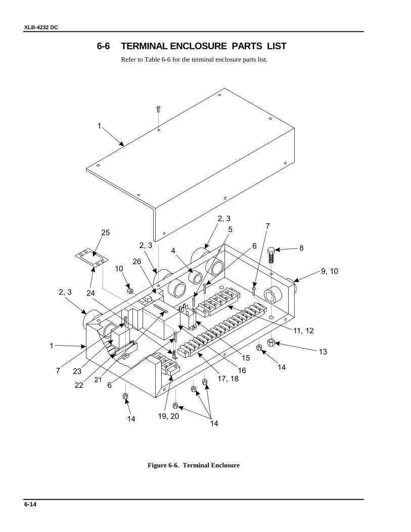
XLB-4232 DC
6-14
6-6 TERMINAL ENCLOSURE PARTS LIST Refer to Table 6-6 for the terminal enclosure parts list.
1
2, 3
2, 3
2, 3
4
9, 10
8
13
19, 20
6
75
7
6
1414
14
10
24
25
17, 18
15
16
11, 12
26
2122
23
1
Figure 6-6. Terminal Enclosure
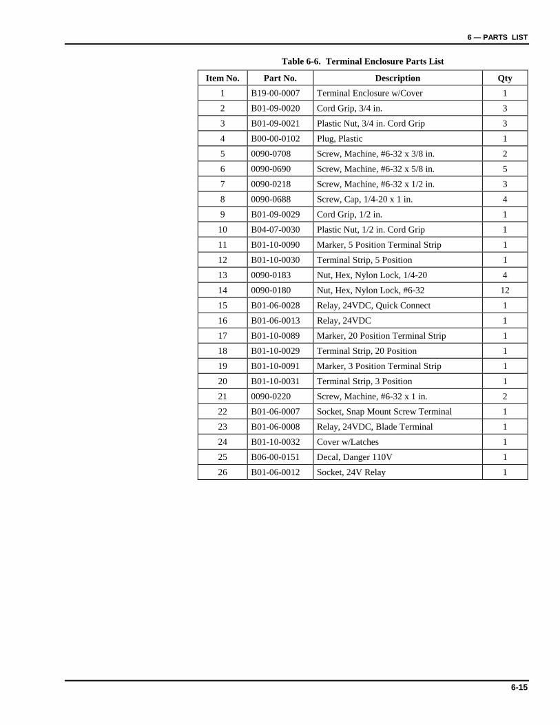
6 — PARTS LIST
6-15
Table 6-6. Terminal Enclosure Parts List
Item No. Part No. Description Qty 1 B19-00-0007 Terminal Enclosure w/Cover 1
2 B01-09-0020 Cord Grip, 3/4 in. 3
3 B01-09-0021 Plastic Nut, 3/4 in. Cord Grip 3
4 B00-00-0102 Plug, Plastic 1
5 0090-0708 Screw, Machine, #6-32 x 3/8 in. 2
6 0090-0690 Screw, Machine, #6-32 x 5/8 in. 5
7 0090-0218 Screw, Machine, #6-32 x 1/2 in. 3
8 0090-0688 Screw, Cap, 1/4-20 x 1 in. 4
9 B01-09-0029 Cord Grip, 1/2 in. 1
10 B04-07-0030 Plastic Nut, 1/2 in. Cord Grip 1
11 B01-10-0090 Marker, 5 Position Terminal Strip 1
12 B01-10-0030 Terminal Strip, 5 Position 1
13 0090-0183 Nut, Hex, Nylon Lock, 1/4-20 4
14 0090-0180 Nut, Hex, Nylon Lock, #6-32 12
15 B01-06-0028 Relay, 24VDC, Quick Connect 1
16 B01-06-0013 Relay, 24VDC 1
17 B01-10-0089 Marker, 20 Position Terminal Strip 1
18 B01-10-0029 Terminal Strip, 20 Position 1
19 B01-10-0091 Marker, 3 Position Terminal Strip 1
20 B01-10-0031 Terminal Strip, 3 Position 1
21 0090-0220 Screw, Machine, #6-32 x 1 in. 2
22 B01-06-0007 Socket, Snap Mount Screw Terminal 1
23 B01-06-0008 Relay, 24VDC, Blade Terminal 1
24 B01-10-0032 Cover w/Latches 1
25 B06-00-0151 Decal, Danger 110V 1
26 B01-06-0012 Socket, 24V Relay 1
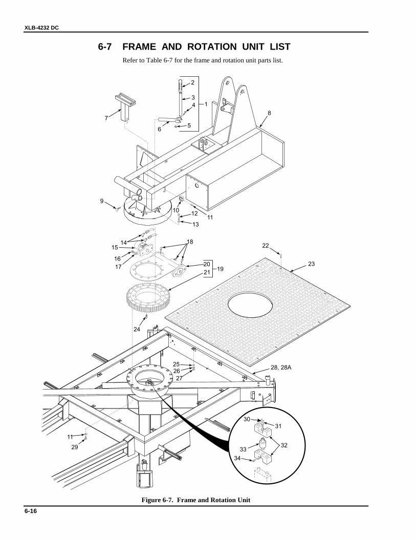
XLB-4232 DC
6-16
6-7 FRAME AND ROTATION UNIT LIST Refer to Table 6-7 for the frame and rotation unit parts list.
6
7
5
4
3
2
1
8
9
10
1112
20
1415
17
16
24
18
23
28, 28A
29
11
27
2625
22
13
2119
31
3233
34
30
Figure 6-7. Frame and Rotation Unit
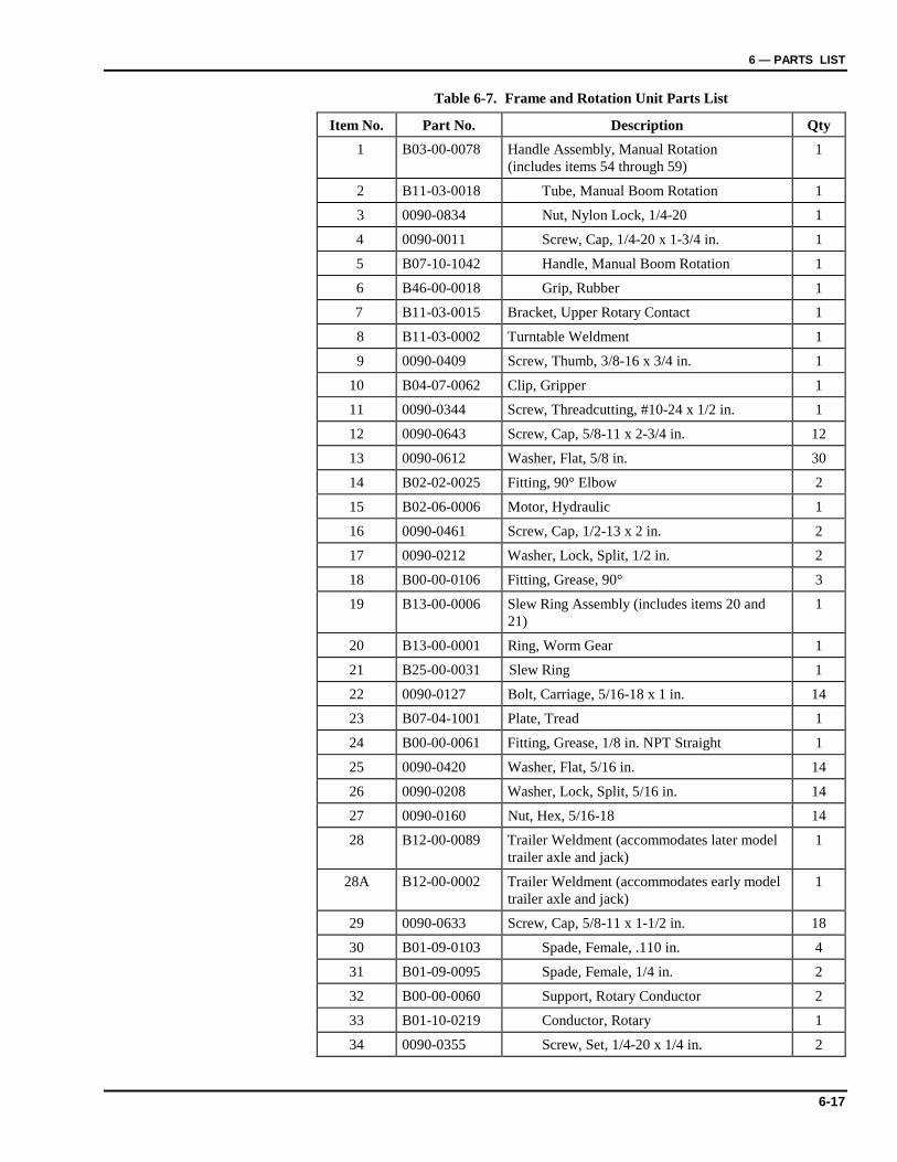
6 — PARTS LIST
6-17
Table 6-7. Frame and Rotation Unit Parts List
Item No. Part No. Description Qty 1 B03-00-0078 Handle Assembly, Manual Rotation
(includes items 54 through 59) 1
2 B11-03-0018 Tube, Manual Boom Rotation 1
3 0090-0834 Nut, Nylon Lock, 1/4-20 1
4 0090-0011 Screw, Cap, 1/4-20 x 1-3/4 in. 1
5 B07-10-1042 Handle, Manual Boom Rotation 1
6 B46-00-0018 Grip, Rubber 1
7 B11-03-0015 Bracket, Upper Rotary Contact 1
8 B11-03-0002 Turntable Weldment 1
9 0090-0409 Screw, Thumb, 3/8-16 x 3/4 in. 1
10 B04-07-0062 Clip, Gripper 1
11 0090-0344 Screw, Threadcutting, #10-24 x 1/2 in. 1
12 0090-0643 Screw, Cap, 5/8-11 x 2-3/4 in. 12
13 0090-0612 Washer, Flat, 5/8 in. 30
14 B02-02-0025 Fitting, 90° Elbow 2
15 B02-06-0006 Motor, Hydraulic 1
16 0090-0461 Screw, Cap, 1/2-13 x 2 in. 2
17 0090-0212 Washer, Lock, Split, 1/2 in. 2
18 B00-00-0106 Fitting, Grease, 90° 3
19 B13-00-0006 Slew Ring Assembly (includes items 20 and 21)
1
20 B13-00-0001 Ring, Worm Gear 1
21 B25-00-0031 Slew Ring 1
22 0090-0127 Bolt, Carriage, 5/16-18 x 1 in. 14
23 B07-04-1001 Plate, Tread 1
24 B00-00-0061 Fitting, Grease, 1/8 in. NPT Straight 1
25 0090-0420 Washer, Flat, 5/16 in. 14
26 0090-0208 Washer, Lock, Split, 5/16 in. 14
27 0090-0160 Nut, Hex, 5/16-18 14
28 B12-00-0089 Trailer Weldment (accommodates later model trailer axle and jack)
1
28A B12-00-0002 Trailer Weldment (accommodates early model trailer axle and jack)
1
29 0090-0633 Screw, Cap, 5/8-11 x 1-1/2 in. 18
30 B01-09-0103 Spade, Female, .110 in. 4
31 B01-09-0095 Spade, Female, 1/4 in. 2
32 B00-00-0060 Support, Rotary Conductor 2
33 B01-10-0219 Conductor, Rotary 1
34 0090-0355 Screw, Set, 1/4-20 x 1/4 in. 2
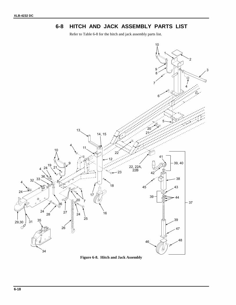
XLB-4232 DC
6-18
6-8 HITCH AND JACK ASSEMBLY PARTS LIST Refer to Table 6-8 for the hitch and jack assembly parts list.
98
7
6
1
2
3
4
5
20
21
38
45
22
22, 22A,22B
47
18
48
16
46
17
23
12
14, 15
720
2724
25
2428
4
35
24
29,30 31
34
26
363332
36
4 2419
8
21
9
10
411
13
10
39
4439
43
39, 40
37
42
41
Figure 6-8. Hitch and Jack Assembly
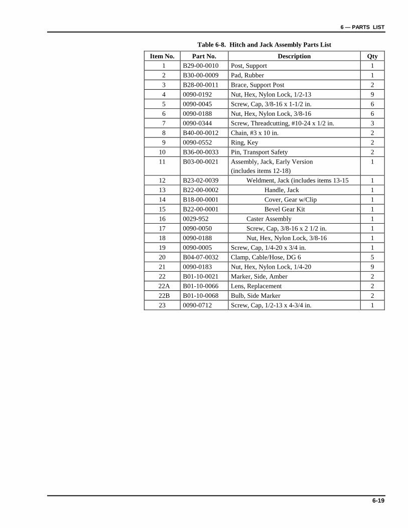
6 — PARTS LIST
6-19
Table 6-8. Hitch and Jack Assembly Parts List
Item No. Part No. Description Qty 1 B29-00-0010 Post, Support 1 2 B30-00-0009 Pad, Rubber 1 3 B28-00-0011 Brace, Support Post 2 4 0090-0192 Nut, Hex, Nylon Lock, 1/2-13 9 5 0090-0045 Screw, Cap, 3/8-16 x 1-1/2 in. 6 6 0090-0188 Nut, Hex, Nylon Lock, 3/8-16 6 7 0090-0344 Screw, Threadcutting, #10-24 x 1/2 in. 3 8 B40-00-0012 Chain, #3 x 10 in. 2 9 0090-0552 Ring, Key 2
10 B36-00-0033 Pin, Transport Safety 2 11 B03-00-0021 Assembly, Jack, Early Version
(includes items 12-18) 1
12 B23-02-0039 Weldment, Jack (includes items 13-15 1 13 B22-00-0002 Handle, Jack 1 14 B18-00-0001 Cover, Gear w/Clip 1 15 B22-00-0001 Bevel Gear Kit 1 16 0029-952 Caster Assembly 1 17 0090-0050 Screw, Cap, 3/8-16 x 2 1/2 in. 1 18 0090-0188 Nut, Hex, Nylon Lock, 3/8-16 1 19 0090-0005 Screw, Cap, 1/4-20 x 3/4 in. 1 20 B04-07-0032 Clamp, Cable/Hose, DG 6 5 21 0090-0183 Nut, Hex, Nylon Lock, 1/4-20 9 22 B01-10-0021 Marker, Side, Amber 2 22A B01-10-0066 Lens, Replacement 2 22B B01-10-0068 Bulb, Side Marker 2 23 0090-0712 Screw, Cap, 1/2-13 x 4-3/4 in. 1
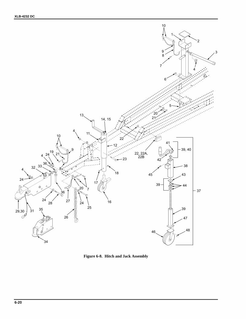
XLB-4232 DC
6-20
98
7
6
1
2
3
4
5
20
21
38
45
22
22, 22A,22B
47
18
48
16
46
17
23
12
14, 15
720
2724
25
2428
4
35
24
29,30 31
34
26
363332
36
4 2419
8
21
9
10
411
13
10
39
4439
43
39, 40
37
42
41
Figure 6-8. Hitch and Jack Assembly
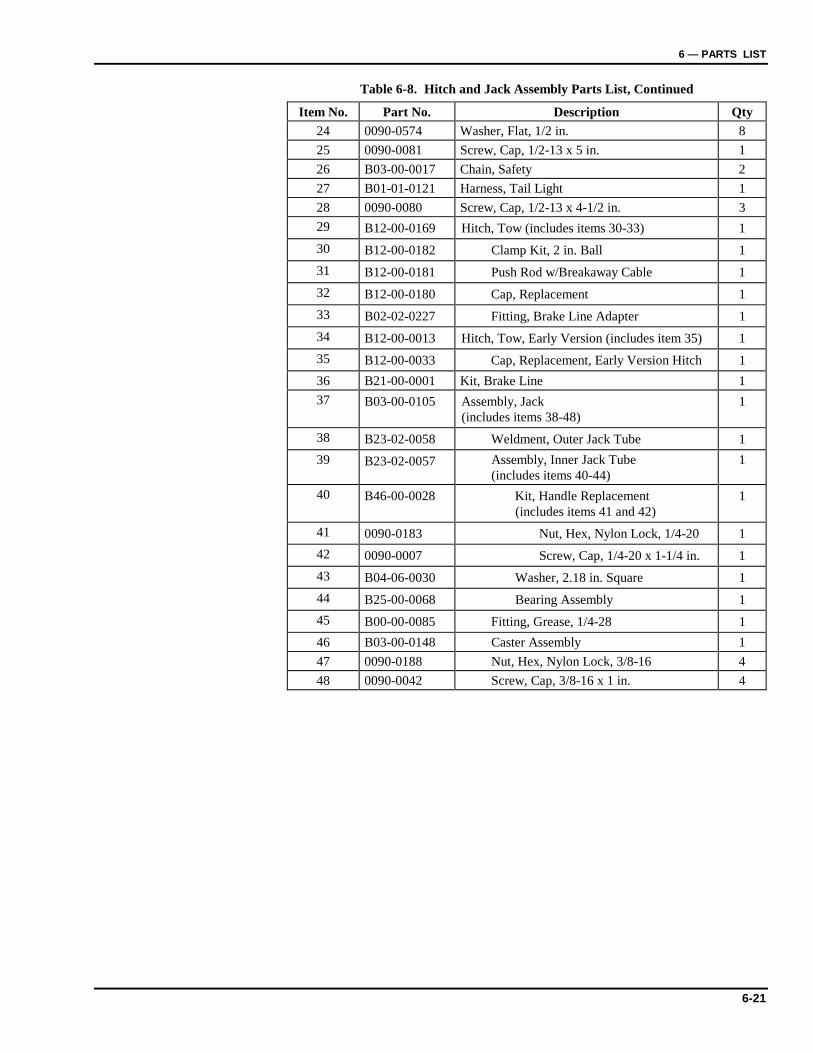
6 — PARTS LIST
6-21
Table 6-8. Hitch and Jack Assembly Parts List, Continued
Item No. Part No. Description Qty 24 0090-0574 Washer, Flat, 1/2 in. 8 25 0090-0081 Screw, Cap, 1/2-13 x 5 in. 1 26 B03-00-0017 Chain, Safety 2 27 B01-01-0121 Harness, Tail Light 1 28 0090-0080 Screw, Cap, 1/2-13 x 4-1/2 in. 3 29 B12-00-0169 Hitch, Tow (includes items 30-33) 1 30 B12-00-0182 Clamp Kit, 2 in. Ball 1 31 B12-00-0181 Push Rod w/Breakaway Cable 1 32 B12-00-0180 Cap, Replacement 1 33 B02-02-0227 Fitting, Brake Line Adapter 1 34 B12-00-0013 Hitch, Tow, Early Version (includes item 35) 1 35 B12-00-0033 Cap, Replacement, Early Version Hitch 1 36 B21-00-0001 Kit, Brake Line 1 37 B03-00-0105 Assembly, Jack
(includes items 38-48) 1
38 B23-02-0058 Weldment, Outer Jack Tube 1 39 B23-02-0057 Assembly, Inner Jack Tube
(includes items 40-44) 1
40 B46-00-0028 Kit, Handle Replacement (includes items 41 and 42)
1
41 0090-0183 Nut, Hex, Nylon Lock, 1/4-20 1 42 0090-0007 Screw, Cap, 1/4-20 x 1-1/4 in. 1 43 B04-06-0030 Washer, 2.18 in. Square 1 44 B25-00-0068 Bearing Assembly 1 45 B00-00-0085 Fitting, Grease, 1/4-28 1 46 B03-00-0148 Caster Assembly 1 47 0090-0188 Nut, Hex, Nylon Lock, 3/8-16 4 48 0090-0042 Screw, Cap, 3/8-16 x 1 in. 4
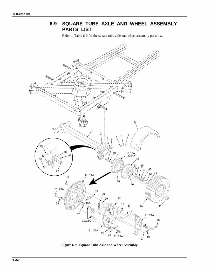
XLB-4232 DC
6-22
6-9 SQUARE TUBE AXLE AND WHEEL ASSEMBLY PARTS LIST
Refer to Table 6-9 for the square tube axle and wheel assembly parts list.
12
3738
36
39
40 41
42 43
4445
11109
56 7
8
1
47
48
47
49
51
50
13,13A,35,35A
14, 14A
15,15A
32,32A
16
17
18
28
29
30
31
33
34
26
1927
21, 21A
21, 21A22
23
24
25
21, 21A
21, 21A
20
34
2
46
Figure 6-9. Square Tube Axle and Wheel Assembly
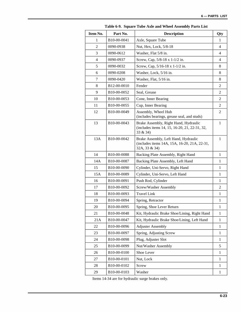
6 — PARTS LIST
6-23
Table 6-9. Square Tube Axle and Wheel Assembly Parts List
Item No. Part No. Description Qty 1 B10-00-0041 Axle, Square Tube 1
2 0090-0938 Nut, Hex, Lock, 5/8-18 4
3 0090-0612 Washer, Flat 5/8 in. 4
4 0090-0937 Screw, Cap, 5/8-18 x 1-1/2 in. 4
5 0090-0032 Screw, Cap, 5/16-18 x 1-1/2 in. 8
6 0090-0208 Washer, Lock, 5/16 in. 8
7 0090-0420 Washer, Flat, 5/16 in. 8
8 B12-00-0010 Fender 2
9 B10-00-0052 Seal, Grease 2
10 B10-00-0053 Cone, Inner Bearing 2
11 B10-00-0055 Cup, Inner Bearing 2
12 B10-00-0049 Assembly, Wheel Hub (includes bearings, grease seal, and studs)
2
13 B10-00-0043 Brake Assembly, Right Hand, Hydraulic (includes items 14, 15, 16-20, 21, 22-31, 32, 33 & 34)
1
13A B10-00-0042 Brake Assembly, Left Hand, Hydraulic (includes items 14A, 15A, 16-20, 21A, 22-31, 32A, 33 & 34)
1
14 B10-00-0088 Backing Plate Assembly, Right Hand 1
14A B10-00-0087 Backing Plate Assembly, Left Hand 1
15 B10-00-0090 Cylinder, Uni-Servo, Right Hand 1
15A B10-00-0089 Cylinder, Uni-Servo, Left Hand 1
16 B10-00-0091 Push Rod, Cylinder 1
17 B10-00-0092 Screw/Washer Assembly 2
18 B10-00-0093 Travel Link 1
19 B10-00-0094 Spring, Retractor 1
20 B10-00-0095 Spring, Shoe Lever Return 1
21 B10-00-0048 Kit, Hydraulic Brake Shoe/Lining, Right Hand 1
21A B10-00-0047 Kit, Hydraulic Brake Shoe/Lining, Left Hand 1
22 B10-00-0096 Adjuster Assembly 1
23 B10-00-0097 Spring, Adjusting Screw 1
24 B10-00-0098 Plug, Adjuster Slot 1
25 B10-00-0099 Nut/Washer Assembly 5
26 B10-00-0100 Shoe Lever 1
27 B10-00-0101 Nut, Lock 1
28 B10-00-0102 Screw 1
29 B10-00-0103 Washer 1
Items 14-34 are for hydraulic surge brakes only.
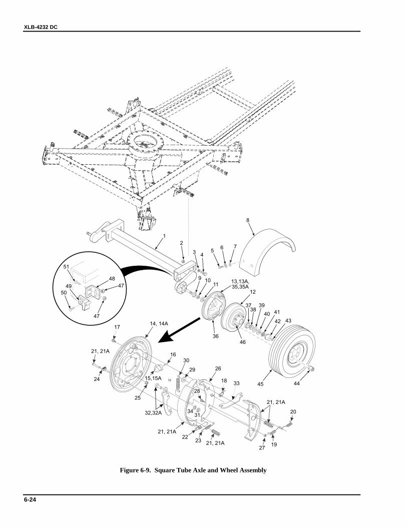
XLB-4232 DC
6-24
12
3738
36
39
40 41
42 43
4445
11109
56 7
8
1
47
48
47
49
51
50
13,13A,35,35A
14, 14A
15,15A
32,32A
16
17
18
28
29
30
31
33
34
26
1927
21, 21A
21, 21A22
23
24
25
21, 21A
21, 21A
20
34
2
46
Figure 6-9. Square Tube Axle and Wheel Assembly
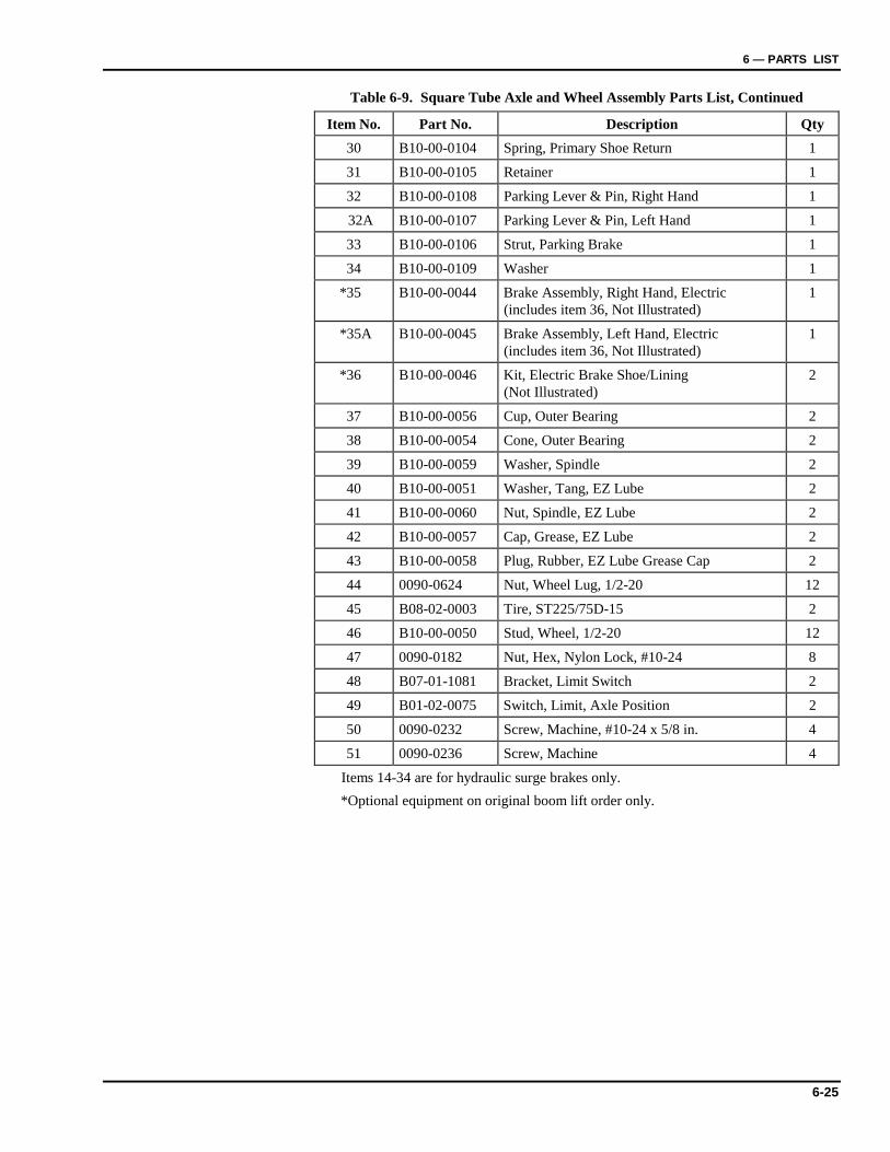
6 — PARTS LIST
6-25
Table 6-9. Square Tube Axle and Wheel Assembly Parts List, Continued
Item No. Part No. Description Qty 30 B10-00-0104 Spring, Primary Shoe Return 1
31 B10-00-0105 Retainer 1
32 B10-00-0108 Parking Lever & Pin, Right Hand 1
32A B10-00-0107 Parking Lever & Pin, Left Hand 1
33 B10-00-0106 Strut, Parking Brake 1
34 B10-00-0109 Washer 1
*35 B10-00-0044 Brake Assembly, Right Hand, Electric (includes item 36, Not Illustrated)
1
*35A B10-00-0045 Brake Assembly, Left Hand, Electric (includes item 36, Not Illustrated)
1
*36 B10-00-0046 Kit, Electric Brake Shoe/Lining (Not Illustrated)
2
37 B10-00-0056 Cup, Outer Bearing 2
38 B10-00-0054 Cone, Outer Bearing 2
39 B10-00-0059 Washer, Spindle 2
40 B10-00-0051 Washer, Tang, EZ Lube 2
41 B10-00-0060 Nut, Spindle, EZ Lube 2
42 B10-00-0057 Cap, Grease, EZ Lube 2
43 B10-00-0058 Plug, Rubber, EZ Lube Grease Cap 2
44 0090-0624 Nut, Wheel Lug, 1/2-20 12
45 B08-02-0003 Tire, ST225/75D-15 2
46 B10-00-0050 Stud, Wheel, 1/2-20 12
47 0090-0182 Nut, Hex, Nylon Lock, #10-24 8
48 B07-01-1081 Bracket, Limit Switch 2
49 B01-02-0075 Switch, Limit, Axle Position 2
50 0090-0232 Screw, Machine, #10-24 x 5/8 in. 4
51 0090-0236 Screw, Machine 4
Items 14-34 are for hydraulic surge brakes only. *Optional equipment on original boom lift order only.
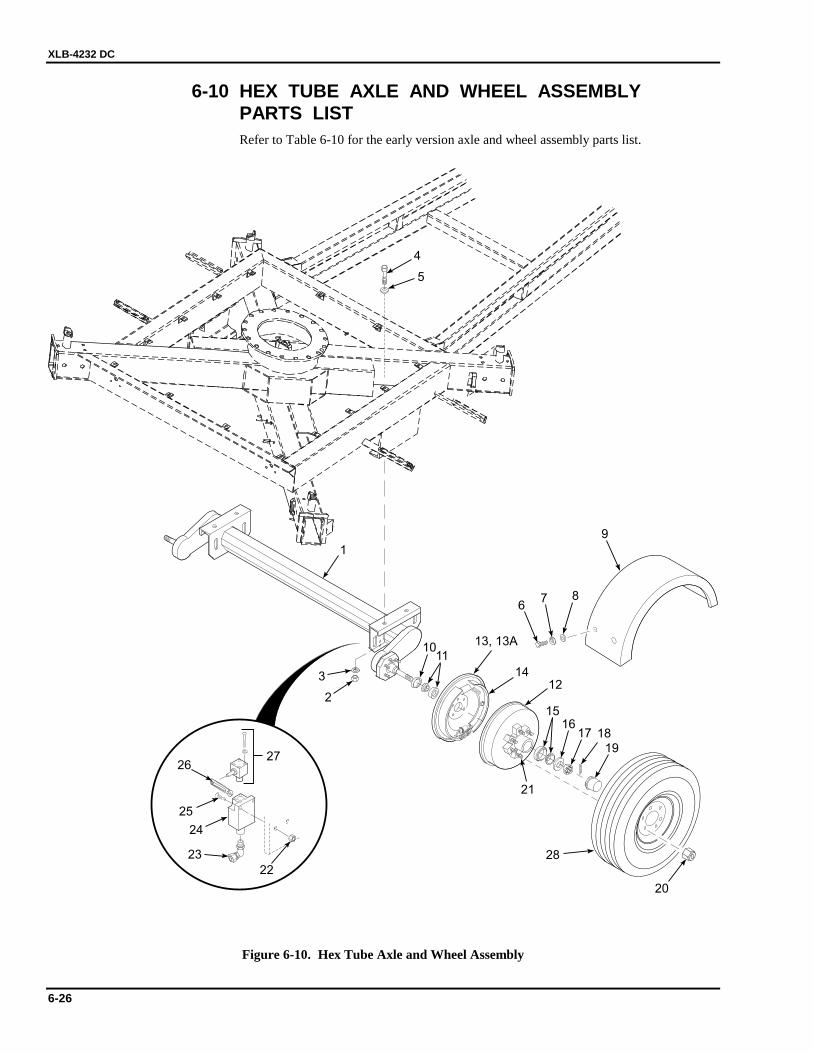
XLB-4232 DC
6-26
6-10 HEX TUBE AXLE AND WHEEL ASSEMBLY PARTS LIST
Refer to Table 6-10 for the early version axle and wheel assembly parts list.
12
1516
17 18
19
20
1110
3
5
4
2
1
27
23
22
24
25
26
14
13, 13A
21
28
67 8
9
Figure 6-10. Hex Tube Axle and Wheel Assembly
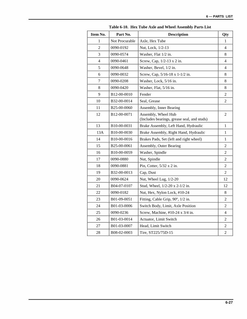
6 — PARTS LIST
6-27
Table 6-10. Hex Tube Axle and Wheel Assembly Parts List
Item No. Part No. Description Qty 1 Not Procurable Axle, Hex Tube 1
2 0090-0192 Nut, Lock, 1/2-13 4
3 0090-0574 Washer, Flat 1/2 in. 8
4 0090-0461 Screw, Cap, 1/2-13 x 2 in. 4
5 0090-0648 Washer, Bevel, 1/2 in. 4
6 0090-0032 Screw, Cap, 5/16-18 x 1-1/2 in. 8
7 0090-0208 Washer, Lock, 5/16 in. 8
8 0090-0420 Washer, Flat, 5/16 in. 8
9 B12-00-0010 Fender 2
10 B32-00-0014 Seal, Grease 2
11 B25-00-0060 Assembly, Inner Bearing
12 B12-00-0071 Assembly, Wheel Hub (Includes bearings, grease seal, and studs)
2
13 B10-00-0031 Brake Assembly, Left Hand, Hydraulic 1
13A B10-00-0030 Brake Assembly, Right Hand, Hydraulic 1
14 B10-00-0016 Brakes Pads, Set (left and right wheel) 1
15 B25-00-0061 Assembly, Outer Bearing 2
16 B10-00-0059 Washer, Spindle 2
17 0090-0880 Nut, Spindle 2
18 0090-0881 Pin, Cotter, 5/32 x 2 in. 2
19 B32-00-0013 Cap, Dust 2
20 0090-0624 Nut, Wheel Lug, 1/2-20 12
21 B04-07-0107 Stud, Wheel, 1/2-20 x 2-1/2 in. 12
22 0090-0182 Nut, Hex, Nylon Lock, #10-24 8
23 B01-09-0051 Fitting, Cable Grip, 90º, 1/2 in. 2
24 B01-03-0006 Switch Body, Limit, Axle Position 2
25 0090-0236 Screw, Machine, #10-24 x 3/4 in. 4
26 B01-03-0014 Actuator, Limit Switch 2
27 B01-03-0007 Head, Limit Switch 2
28 B08-02-0003 Tire, ST225/75D-15 2

XLB-4232 DC
6-28
6-11 TAIL LIGHTS AND OUTRIGGER DISPLAY TRANSMITTER BOX PARTS LIST
Refer to Table 6-11 for the tail lights and outrigger display transmitter box parts list.
2
3 1
5
7
7
8
8
6 1211
1216
14
13
9
10
12
11
12
3
4 15, 15A,15B
Figure 6-11. Tail Lights and Outrigger Display Transmitter Box

6 — PARTS LIST
6-29
Table 6-11. Tail Lights and Outrigger Display Transmitter Box Parts List
Item No. Part No. Description Qty 1 B01-10-0024 Tail Light Assembly, Left 1
2 B29-00-0037 Bracket, License Plate Mounting 1
3 B01-10-0069 Lens, Replacement 2
4 B01-10-0023 Tail Light Assembly, Right 1
5 B01-10-0270 Transmitter, Outrigger Display 1
6 B01-09-0105 Connector, 12 Pin, Outrigger Display, Gray 1
7 B01-09-0107 Insert, 12 Pin, Outrigger Display 2
8 B01-09-0108 Pin, Outrigger Display (3 in gray connector, 12 in black connector)
15
9 B01-09-0106 Connector, 12 Pin, Outrigger Display, Black 1
10 B18-00-0153 Cover, Outrigger Display Transmitter 1
11 0090-0419 Washer, Flat, 1/4 in. 4
12 0090-0183 Nut, Hex, Nylon Lock, 1/4-20 8
13 B04-07-0035 Clamp, Cable/Hose, DG 14 1
14 B04-07-0034 Clamp, Cable/Hose, DG 12 1
15 B01-10-0022 Marker, Side, Red 2
15A B01-10-0067 Lens, Replacement 2
15B B01-10-0068 Bulb, Side Marker 2
16 B04-07-0032 Clamp, Cable/Hose, DG 6 2

XLB-4232 DC
6-30
6-12 RIGHT FRONT/LEFT REAR OUTRIGGERS PARTS LIST Refer to Table 6-12 for the right front/left rear outriggers parts list.
EXTENDSTABIL
IZERS
FOR
LEASTW
HEELCONTACT
7
6
1, 1A
17
18
19
5
32
4
8
9
10
11
15
14 13
1216
3”
18
2021
2223
24
25
26
27
28
29
30, 30A
Figure 6-12. Right Front/Left Rear Outriggers

6 — PARTS LIST
6-31
Table 6-12. Right Front/Left Rear Outriggers Parts List
Item No. Part No. Description Qty 1 B23-01-0087 Outrigger, Front, Passenger Side 1
1A B23-01-0087 Outrigger, Rear, Driver Side 1
2 B00-00-0085 Fitting, Grease, Straight, 1/4-28 1
3 B06-00-0167 Caution Tape, Black and Yellow 1 Roll
4 B23-02-0048 Assembly, Outrigger Jack (includes items 5 through 11)
1
5 B46-00-0028 Kit, Handle Replacement 1
6 0090-0183 Nut, Hex, Nylon Lock, 1/4-20 1
7 0090-0007 Screw, Cap, 1/4-20 x 1-1/4 in. 1
8 B04-06-0030 Washer, 2.18 in. Square 1
9 B25-00-0068 Bearing Kit 1
10 B36-00-0039 Pin 1
11 B23-02-0053 Drop Tube, Quick Adjust 1
12 0090-0909 Screw, Cap, 5/8-11 x 3-1/4 in. 1
13 B00-00-0009 Fitting, Grease, Straight, 3/16 in. 1
14 B23-02-0047 Weldment, Footpad 1
15 0090-0194 Nut, Hex, Nylon Lock, 5/8-11 1
16 B06-00-0036 Decal, Lube Weekly 1
17 B01-03-0031 Magnet, Proximity 1
18 0090-0813 Screw, Machine, #8-32 x 3/4 in. 4
19 0090-0181 Nut, Hex, Nylon Lock, #8-32 4
20 B31-00-0006 B31-00-0027
Plate, Guide, 5/16” Thick or Plate, Guide, 1/4” Thick
1
21 B36-00-0004 Pin, Plunger 1
22 0090-0319 Pin, Roll, 1/4 x 1-1/4 in. 1
23 B39-00-0004 Spring 1
24 B46-00-0005 Handle, Outrigger Pin 1
25 B46-00-0008 Knob, Ball 1
26 0090-0476 Washer, External Tooth Star, 1/2 in. 3
27 0090-0387 Screw, Socket Head Cap, 1/2-13 x 1/2 in. 3
28 B04-07-0032 Clamp, Cable/Hose, DG-6 3
29 0090-0183 Nut, Hex, Nylon Lock, 1/4-20 2
30 B01-03-0029 Switch, Magnetic Reed w/72” SJO Cord, Front Outrigger – Passenger Side
1
30A B01-03-0030 Switch, Magnetic Reed w/45” SJO Cord, Rear Outrigger – Driver Side
1
Note: Quantities shown for Items 2-29 are per outrigger.
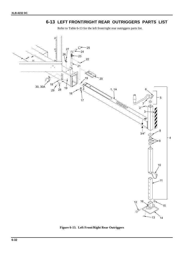
XLB-4232 DC
6-32
6-13 LEFT FRONT/RIGHT REAR OUTRIGGERS PARTS LIST Refer to Table 6-13 for the left front/right rear outriggers parts list.
3/4”
EXTENDSTABILIZERS
FOR
LEAST WHEEL CONTACT
10
11
15
1413
12 16
4
7
6
5
3
2
8
9
1, 1A
17
18
18
19
19
20
21
2223
24
25
26
27
2829
30, 30A
Figure 6-13. Left Front/Right Rear Outriggers
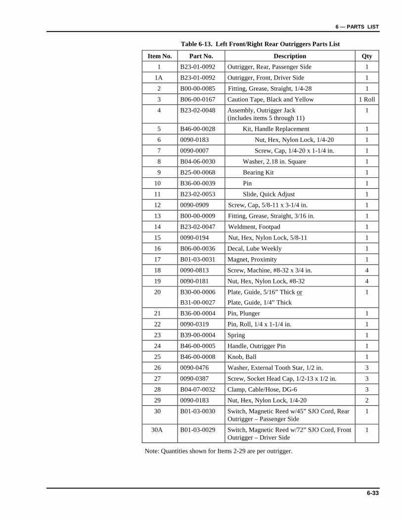
6 — PARTS LIST
6-33
Table 6-13. Left Front/Right Rear Outriggers Parts List
Item No. Part No. Description Qty 1 B23-01-0092 Outrigger, Rear, Passenger Side 1
1A B23-01-0092 Outrigger, Front, Driver Side 1
2 B00-00-0085 Fitting, Grease, Straight, 1/4-28 1
3 B06-00-0167 Caution Tape, Black and Yellow 1 Roll
4 B23-02-0048 Assembly, Outrigger Jack (includes items 5 through 11)
1
5 B46-00-0028 Kit, Handle Replacement 1
6 0090-0183 Nut, Hex, Nylon Lock, 1/4-20 1
7 0090-0007 Screw, Cap, 1/4-20 x 1-1/4 in. 1
8 B04-06-0030 Washer, 2.18 in. Square 1
9 B25-00-0068 Bearing Kit 1
10 B36-00-0039 Pin 1
11 B23-02-0053 Slide, Quick Adjust 1
12 0090-0909 Screw, Cap, 5/8-11 x 3-1/4 in. 1
13 B00-00-0009 Fitting, Grease, Straight, 3/16 in. 1
14 B23-02-0047 Weldment, Footpad 1
15 0090-0194 Nut, Hex, Nylon Lock, 5/8-11 1
16 B06-00-0036 Decal, Lube Weekly 1
17 B01-03-0031 Magnet, Proximity 1
18 0090-0813 Screw, Machine, #8-32 x 3/4 in. 4
19 0090-0181 Nut, Hex, Nylon Lock, #8-32 4
20 B30-00-0006 B31-00-0027
Plate, Guide, 5/16” Thick or Plate, Guide, 1/4” Thick
1
21 B36-00-0004 Pin, Plunger 1
22 0090-0319 Pin, Roll, 1/4 x 1-1/4 in. 1
23 B39-00-0004 Spring 1
24 B46-00-0005 Handle, Outrigger Pin 1
25 B46-00-0008 Knob, Ball 1
26 0090-0476 Washer, External Tooth Star, 1/2 in. 3
27 0090-0387 Screw, Socket Head Cap, 1/2-13 x 1/2 in. 3
28 B04-07-0032 Clamp, Cable/Hose, DG-6 3
29 0090-0183 Nut, Hex, Nylon Lock, 1/4-20 2
30 B01-03-0030 Switch, Magnetic Reed w/45” SJO Cord, Rear Outrigger – Passenger Side
1
30A B01-03-0029 Switch, Magnetic Reed w/72” SJO Cord, Front Outrigger – Driver Side
1
Note: Quantities shown for Items 2-29 are per outrigger.
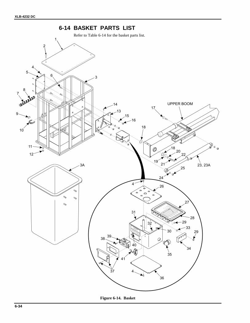
XLB-4232 DC
6-34
6-14 BASKET PARTS LIST Refer to Table 6-14 for the basket parts list.
UPPER BOOM
1500 WATT LOAD LIMIT
CAUTION
SYSTEMVOLTAGE
24VDC
HYDRAULICSYSTEMPRESSURE
1600PSI
WORKHEIGHT
42FT
MAXIMUMPLATFORM
HEIGHT
35FT5IN
CAPACITY
300LB
XLB-4232SPECIFICATIONS
1
3
4
6
78
9
10
11
12
13
14
15
16
17
18
18
1921
24
2022
25
426
27
2829
3330
32
31
29
34
35
36
437
41
3839
40
23, 23A
5
3A
2
Figure 6-14. Basket
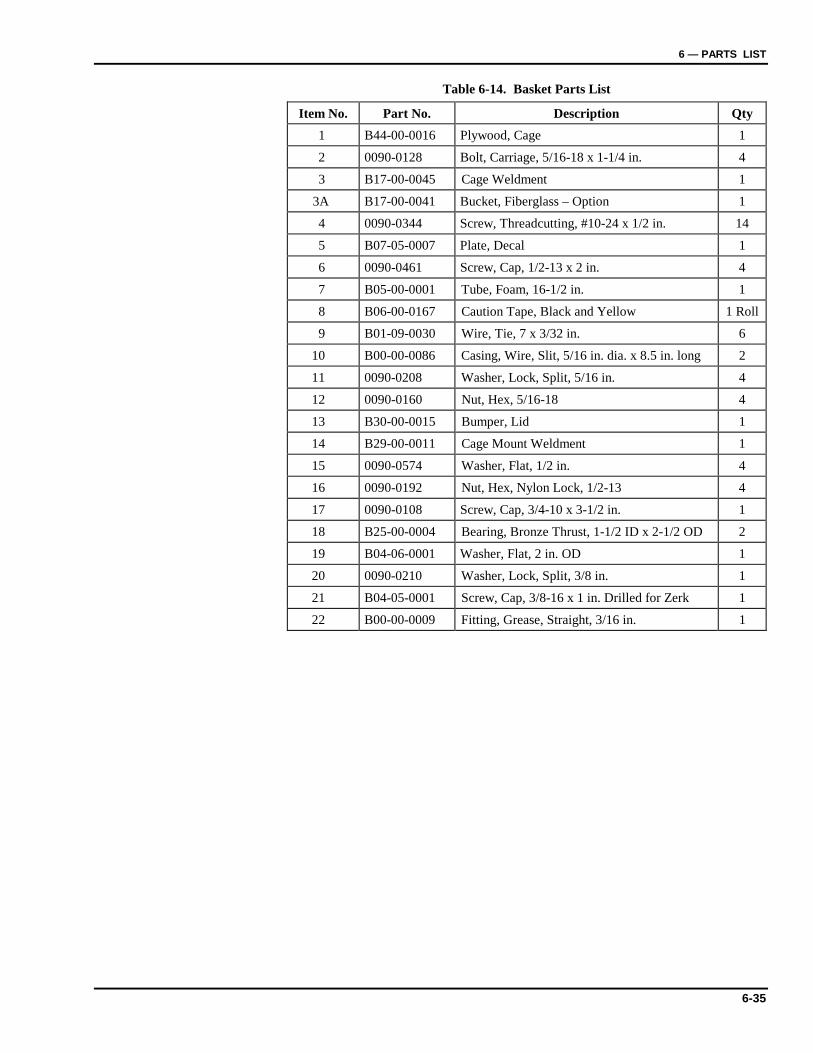
6 — PARTS LIST
6-35
Table 6-14. Basket Parts List
Item No. Part No. Description Qty 1 B44-00-0016 Plywood, Cage 1
2 0090-0128 Bolt, Carriage, 5/16-18 x 1-1/4 in. 4
3 B17-00-0045 Cage Weldment 1
3A B17-00-0041 Bucket, Fiberglass – Option 1
4 0090-0344 Screw, Threadcutting, #10-24 x 1/2 in. 14
5 B07-05-0007 Plate, Decal 1
6 0090-0461 Screw, Cap, 1/2-13 x 2 in. 4
7 B05-00-0001 Tube, Foam, 16-1/2 in. 1
8 B06-00-0167 Caution Tape, Black and Yellow 1 Roll
9 B01-09-0030 Wire, Tie, 7 x 3/32 in. 6
10 B00-00-0086 Casing, Wire, Slit, 5/16 in. dia. x 8.5 in. long 2
11 0090-0208 Washer, Lock, Split, 5/16 in. 4
12 0090-0160 Nut, Hex, 5/16-18 4
13 B30-00-0015 Bumper, Lid 1
14 B29-00-0011 Cage Mount Weldment 1
15 0090-0574 Washer, Flat, 1/2 in. 4
16 0090-0192 Nut, Hex, Nylon Lock, 1/2-13 4
17 0090-0108 Screw, Cap, 3/4-10 x 3-1/2 in. 1
18 B25-00-0004 Bearing, Bronze Thrust, 1-1/2 ID x 2-1/2 OD 2
19 B04-06-0001 Washer, Flat, 2 in. OD 1
20 0090-0210 Washer, Lock, Split, 3/8 in. 1
21 B04-05-0001 Screw, Cap, 3/8-16 x 1 in. Drilled for Zerk 1
22 B00-00-0009 Fitting, Grease, Straight, 3/16 in. 1
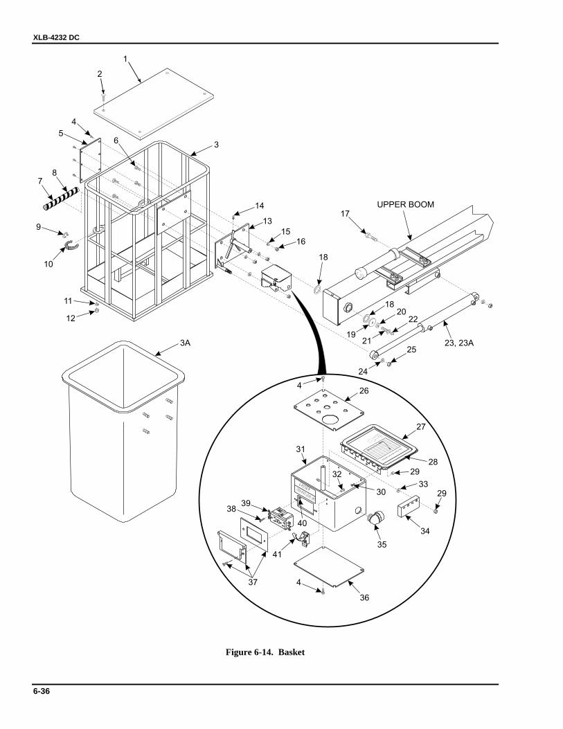
XLB-4232 DC
6-36
UPPER BOOM
1500 WATT LOAD LIMIT
CAUTION
SYSTEMVOLTAGE
24VDC
HYDRAULICSYSTEMPRESSURE
1600PSI
WORKHEIGHT
42FT
MAXIMUMPLATFORM
HEIGHT
35FT5IN
CAPACITY
300LB
XLB-4232SPECIFICATIONS
1
3
4
6
78
9
10
11
12
13
14
15
16
17
18
18
1921
24
2022
25
426
27
2829
3330
32
31
29
34
35
36
437
41
3839
40
23, 23A
5
3A
2
Figure 6-14. Basket
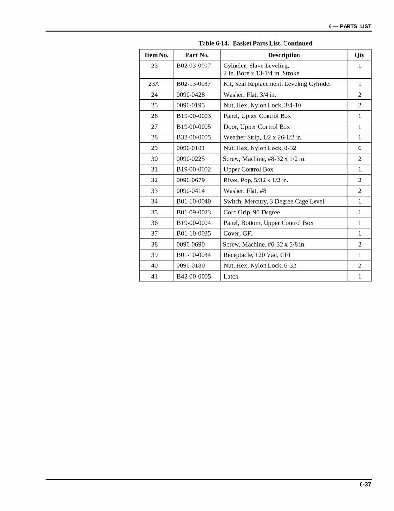
6 — PARTS LIST
6-37
Table 6-14. Basket Parts List, Continued
Item No. Part No. Description Qty 23 B02-03-0007 Cylinder, Slave Leveling,
2 in. Bore x 13-1/4 in. Stroke 1
23A B02-13-0037 Kit, Seal Replacement, Leveling Cylinder 1
24 0090-0428 Washer, Flat, 3/4 in. 2
25 0090-0195 Nut, Hex, Nylon Lock, 3/4-10 2
26 B19-00-0003 Panel, Upper Control Box 1
27 B19-00-0005 Door, Upper Control Box 1
28 B32-00-0005 Weather Strip, 1/2 x 26-1/2 in. 1
29 0090-0181 Nut, Hex, Nylon Lock, 8-32 6
30 0090-0225 Screw, Machine, #8-32 x 1/2 in. 2
31 B19-00-0002 Upper Control Box 1
32 0090-0679 Rivet, Pop, 5/32 x 1/2 in. 2
33 0090-0414 Washer, Flat, #8 2
34 B01-10-0040 Switch, Mercury, 3 Degree Cage Level 1
35 B01-09-0023 Cord Grip, 90 Degree 1
36 B19-00-0004 Panel, Bottom, Upper Control Box 1
37 B01-10-0035 Cover, GFI 1
38 0090-0690 Screw, Machine, #6-32 x 5/8 in. 2
39 B01-10-0034 Receptacle, 120 Vac, GFI 1
40 0090-0180 Nut, Hex, Nylon Lock, 6-32 2
41 B42-00-0005 Latch 1
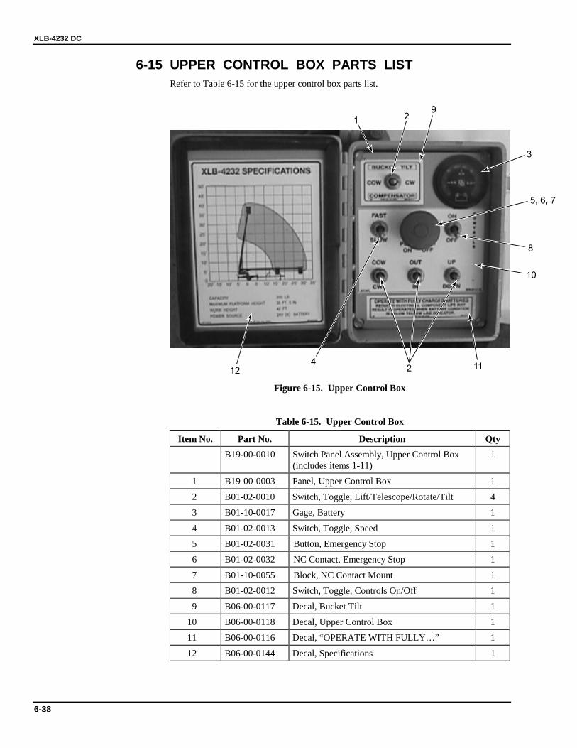
XLB-4232 DC
6-38
6-15 UPPER CONTROL BOX PARTS LIST Refer to Table 6-15 for the upper control box parts list.
1 29
2
3
4
5, 6, 7
8
10
1112
Figure 6-15. Upper Control Box
Table 6-15. Upper Control Box
Item No. Part No. Description Qty B19-00-0010 Switch Panel Assembly, Upper Control Box
(includes items 1-11) 1
1 B19-00-0003 Panel, Upper Control Box 1
2 B01-02-0010 Switch, Toggle, Lift/Telescope/Rotate/Tilt 4
3 B01-10-0017 Gage, Battery 1
4 B01-02-0013 Switch, Toggle, Speed 1
5 B01-02-0031 Button, Emergency Stop 1
6 B01-02-0032 NC Contact, Emergency Stop 1
7 B01-10-0055 Block, NC Contact Mount 1
8 B01-02-0012 Switch, Toggle, Controls On/Off 1
9 B06-00-0117 Decal, Bucket Tilt 1
10 B06-00-0118 Decal, Upper Control Box 1
11 B06-00-0116 Decal, “OPERATE WITH FULLY…” 1
12 B06-00-0144 Decal, Specifications 1
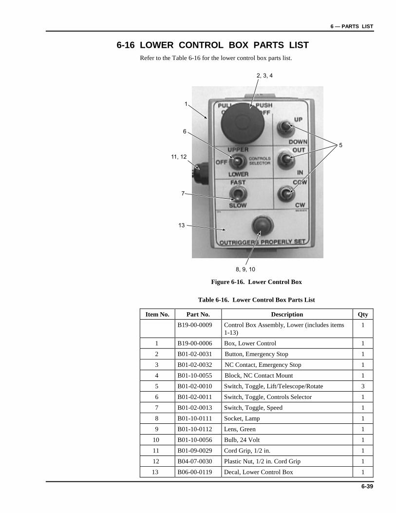
6 — PARTS LIST
6-39
6-16 LOWER CONTROL BOX PARTS LIST Refer to the Table 6-16 for the lower control box parts list.
1
6
7
13
11, 12
8, 9, 10
5
2, 3, 4
Figure 6-16. Lower Control Box
Table 6-16. Lower Control Box Parts List
Item No. Part No. Description Qty B19-00-0009 Control Box Assembly, Lower (includes items
1-13) 1
1 B19-00-0006 Box, Lower Control 1
2 B01-02-0031 Button, Emergency Stop 1
3 B01-02-0032 NC Contact, Emergency Stop 1
4 B01-10-0055 Block, NC Contact Mount 1
5 B01-02-0010 Switch, Toggle, Lift/Telescope/Rotate 3
6 B01-02-0011 Switch, Toggle, Controls Selector 1
7 B01-02-0013 Switch, Toggle, Speed 1
8 B01-10-0111 Socket, Lamp 1
9 B01-10-0112 Lens, Green 1
10 B01-10-0056 Bulb, 24 Volt 1
11 B01-09-0029 Cord Grip, 1/2 in. 1
12 B04-07-0030 Plastic Nut, 1/2 in. Cord Grip 1
13 B06-00-0119 Decal, Lower Control Box 1
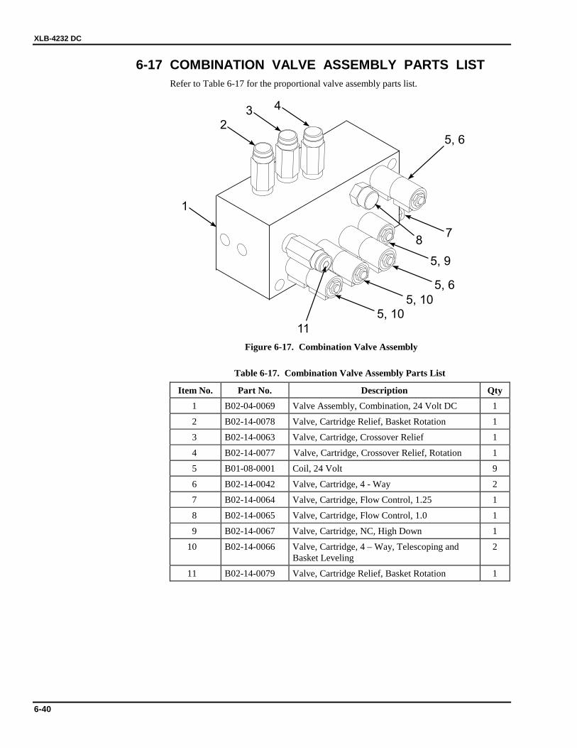
XLB-4232 DC
6-40
6-17 COMBINATION VALVE ASSEMBLY PARTS LIST Refer to Table 6-17 for the proportional valve assembly parts list.
1
23 4
87
5, 9
5, 6
5, 105, 10
11
5, 6
Figure 6-17. Combination Valve Assembly
Table 6-17. Combination Valve Assembly Parts List
Item No. Part No. Description Qty 1 B02-04-0069 Valve Assembly, Combination, 24 Volt DC 1
2 B02-14-0078 Valve, Cartridge Relief, Basket Rotation 1
3 B02-14-0063 Valve, Cartridge, Crossover Relief 1
4 B02-14-0077 Valve, Cartridge, Crossover Relief, Rotation 1
5 B01-08-0001 Coil, 24 Volt 9
6 B02-14-0042 Valve, Cartridge, 4 - Way 2
7 B02-14-0064 Valve, Cartridge, Flow Control, 1.25 1
8 B02-14-0065 Valve, Cartridge, Flow Control, 1.0 1
9 B02-14-0067 Valve, Cartridge, NC, High Down 1
10 B02-14-0066 Valve, Cartridge, 4 – Way, Telescoping and Basket Leveling
2
11 B02-14-0079 Valve, Cartridge Relief, Basket Rotation 1
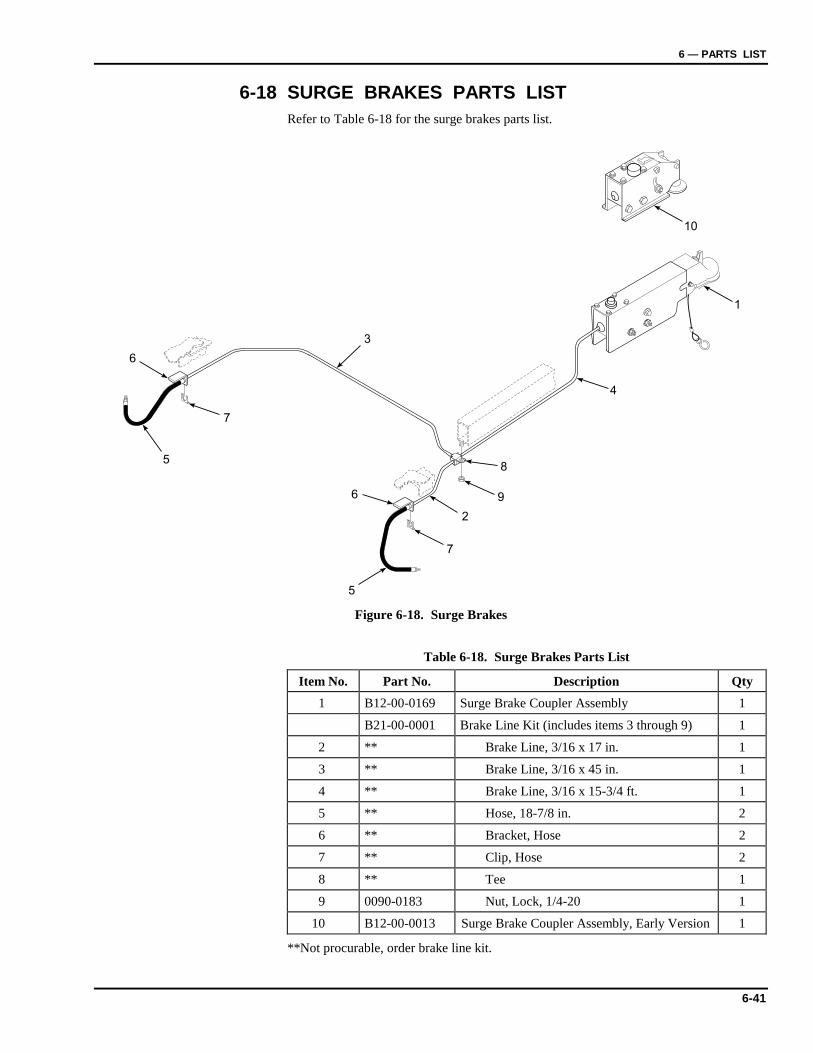
6 — PARTS LIST
6-41
6-18 SURGE BRAKES PARTS LIST Refer to Table 6-18 for the surge brakes parts list.
10
1
4
9
8
2
7
6
5
3
7
5
6
Figure 6-18. Surge Brakes
Table 6-18. Surge Brakes Parts List
Item No. Part No. Description Qty 1 B12-00-0169 Surge Brake Coupler Assembly 1
B21-00-0001 Brake Line Kit (includes items 3 through 9) 1
2 ** Brake Line, 3/16 x 17 in. 1
3 ** Brake Line, 3/16 x 45 in. 1
4 ** Brake Line, 3/16 x 15-3/4 ft. 1
5 ** Hose, 18-7/8 in. 2
6 ** Bracket, Hose 2
7 ** Clip, Hose 2
8 ** Tee 1
9 0090-0183 Nut, Lock, 1/4-20 1
10 B12-00-0013 Surge Brake Coupler Assembly, Early Version 1
**Not procurable, order brake line kit.
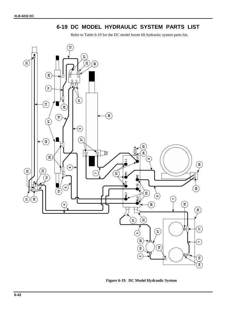
XLB-4232 DC
6-42
6-19 DC MODEL HYDRAULIC SYSTEM PARTS LIST Refer to Table 6-19 for the DC model boom lift hydraulic system parts list.
C2
C1
V1
V2
23
29
33
40
L1 L
2
R1
R2
T2
T1
BL
1
BL
2
1
23
45
6
8
8
7
9
10
11
13
1
15
14
15
16
17
18
19
20
21
21
22
23
23
24
25
26
27
28
29
30
31
32 33
35
36
37
38
39
41
42
12
21
14
Figure 6-19. DC Model Hydraulic System
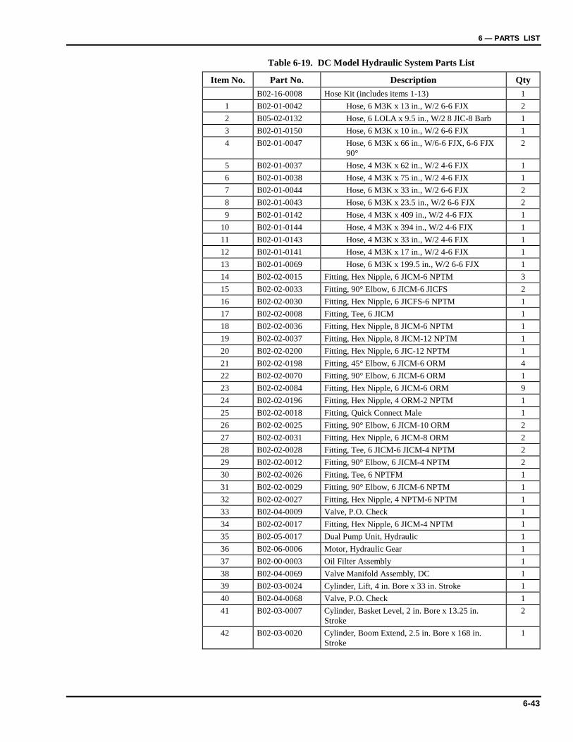
6 — PARTS LIST
6-43
Table 6-19. DC Model Hydraulic System Parts List
Item No. Part No. Description Qty B02-16-0008 Hose Kit (includes items 1-13) 1
1 B02-01-0042 Hose, 6 M3K x 13 in., W/2 6-6 FJX 2 2 B05-02-0132 Hose, 6 LOLA x 9.5 in., W/2 8 JIC-8 Barb 1 3 B02-01-0150 Hose, 6 M3K x 10 in., W/2 6-6 FJX 1 4 B02-01-0047 Hose, 6 M3K x 66 in., W/6-6 FJX, 6-6 FJX
90° 2
5 B02-01-0037 Hose, 4 M3K x 62 in., W/2 4-6 FJX 1 6 B02-01-0038 Hose, 4 M3K x 75 in., W/2 4-6 FJX 1 7 B02-01-0044 Hose, 6 M3K x 33 in., W/2 6-6 FJX 2 8 B02-01-0043 Hose, 6 M3K x 23.5 in., W/2 6-6 FJX 2 9 B02-01-0142 Hose, 4 M3K x 409 in., W/2 4-6 FJX 1
10 B02-01-0144 Hose, 4 M3K x 394 in., W/2 4-6 FJX 1 11 B02-01-0143 Hose, 4 M3K x 33 in., W/2 4-6 FJX 1 12 B02-01-0141 Hose, 4 M3K x 17 in., W/2 4-6 FJX 1 13 B02-01-0069 Hose, 6 M3K x 199.5 in., W/2 6-6 FJX 1 14 B02-02-0015 Fitting, Hex Nipple, 6 JICM-6 NPTM 3 15 B02-02-0033 Fitting, 90° Elbow, 6 JICM-6 JICFS 2 16 B02-02-0030 Fitting, Hex Nipple, 6 JICFS-6 NPTM 1 17 B02-02-0008 Fitting, Tee, 6 JICM 1 18 B02-02-0036 Fitting, Hex Nipple, 8 JICM-6 NPTM 1 19 B02-02-0037 Fitting, Hex Nipple, 8 JICM-12 NPTM 1 20 B02-02-0200 Fitting, Hex Nipple, 6 JIC-12 NPTM 1 21 B02-02-0198 Fitting, 45° Elbow, 6 JICM-6 ORM 4 22 B02-02-0070 Fitting, 90° Elbow, 6 JICM-6 ORM 1 23 B02-02-0084 Fitting, Hex Nipple, 6 JICM-6 ORM 9 24 B02-02-0196 Fitting, Hex Nipple, 4 ORM-2 NPTM 1 25 B02-02-0018 Fitting, Quick Connect Male 1 26 B02-02-0025 Fitting, 90° Elbow, 6 JICM-10 ORM 2 27 B02-02-0031 Fitting, Hex Nipple, 6 JICM-8 ORM 2 28 B02-02-0028 Fitting, Tee, 6 JICM-6 JICM-4 NPTM 2 29 B02-02-0012 Fitting, 90° Elbow, 6 JICM-4 NPTM 2 30 B02-02-0026 Fitting, Tee, 6 NPTFM 1 31 B02-02-0029 Fitting, 90° Elbow, 6 JICM-6 NPTM 1 32 B02-02-0027 Fitting, Hex Nipple, 4 NPTM-6 NPTM 1 33 B02-04-0009 Valve, P.O. Check 1 34 B02-02-0017 Fitting, Hex Nipple, 6 JICM-4 NPTM 1 35 B02-05-0017 Dual Pump Unit, Hydraulic 1 36 B02-06-0006 Motor, Hydraulic Gear 1 37 B02-00-0003 Oil Filter Assembly 1 38 B02-04-0069 Valve Manifold Assembly, DC 1 39 B02-03-0024 Cylinder, Lift, 4 in. Bore x 33 in. Stroke 1 40 B02-04-0068 Valve, P.O. Check 1 41 B02-03-0007 Cylinder, Basket Level, 2 in. Bore x 13.25 in.
Stroke 2
42 B02-03-0020 Cylinder, Boom Extend, 2.5 in. Bore x 168 in. Stroke
1
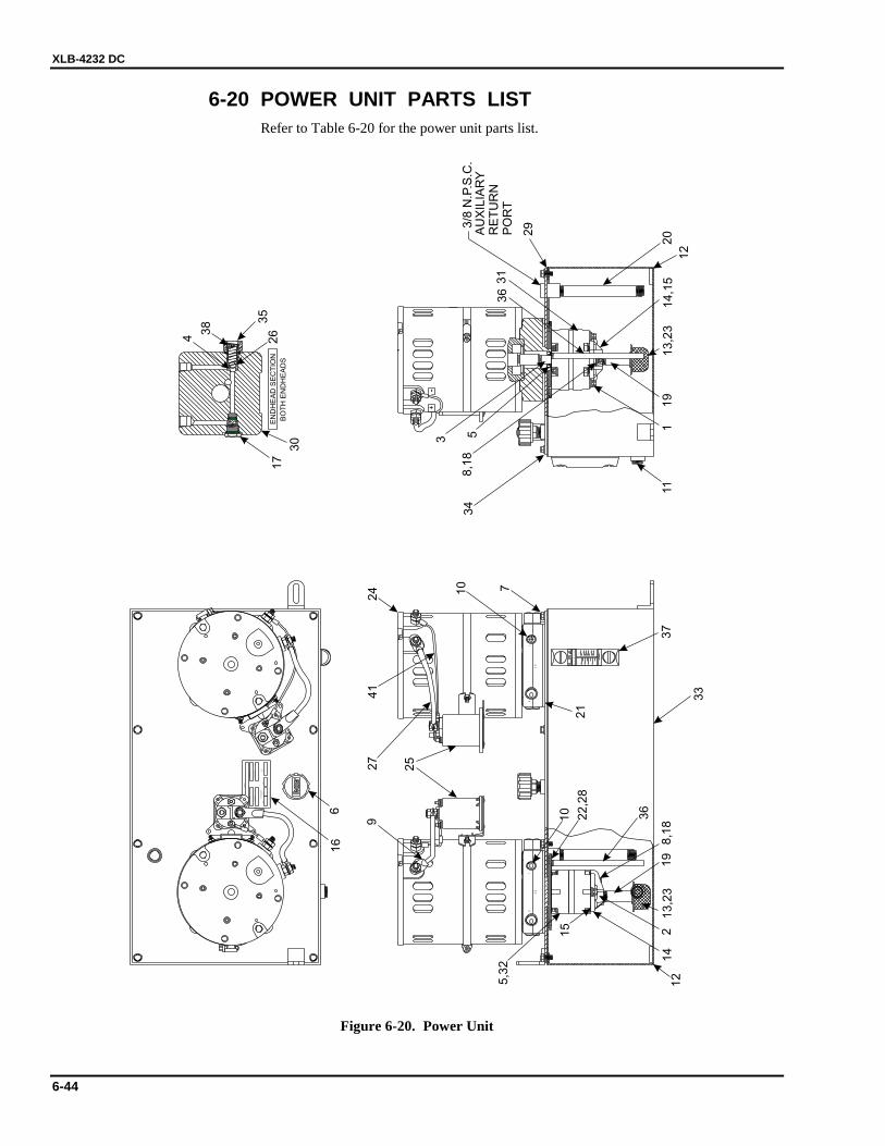
XLB-4232 DC
6-44
6-20 POWER UNIT PARTS LIST Refer to Table 6-20 for the power unit parts list.
CU
STO
MER
MO
DEL
NU
MBER
DATE
CO
DE
SERIA
LN
UM
BER
PART
NU
MBER
PERFO
RM
AN
CE
AM
PS
P.S.
I.G
.P.M
.P.
S.I.
Fenne
rFlu
idPo
we
rIn
c.,
Ro
ckf
ord
,IL
RELI
EF
PT
PT
80
60
40
20
3T
15
0
10
0
50 LG
0
A
10
0
S C
EE
L
F
20
0
2.5
1.6
EN
DH
EA
DS
EC
TIO
N
BO
TH
EN
DH
EA
DS
+-
+
+
-
3/8
N.P
.S.C
.A
UX
ILIA
RY
RE
TU
RN
PO
RT
38 3
517
264
30
111
8,1
813,2
319
20
12
13,2
3
33
8,1
8
214,1
5
16
5
10 22,2
8
366
75,3
2
19
14
15
37
12
36
34
29
31
21
10
3
41
24
27
9
25
Figure 6-20. Power Unit
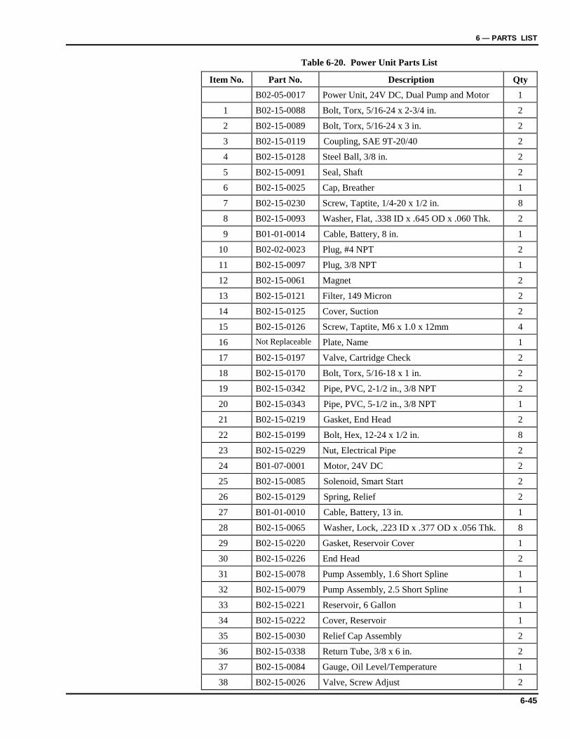
6 — PARTS LIST
6-45
Table 6-20. Power Unit Parts List
Item No. Part No. Description Qty B02-05-0017 Power Unit, 24V DC, Dual Pump and Motor 1
1 B02-15-0088 Bolt, Torx, 5/16-24 x 2-3/4 in. 2
2 B02-15-0089 Bolt, Torx, 5/16-24 x 3 in. 2
3 B02-15-0119 Coupling, SAE 9T-20/40 2
4 B02-15-0128 Steel Ball, 3/8 in. 2
5 B02-15-0091 Seal, Shaft 2
6 B02-15-0025 Cap, Breather 1
7 B02-15-0230 Screw, Taptite, 1/4-20 x 1/2 in. 8
8 B02-15-0093 Washer, Flat, .338 ID x .645 OD x .060 Thk. 2
9 B01-01-0014 Cable, Battery, 8 in. 1
10 B02-02-0023 Plug, #4 NPT 2
11 B02-15-0097 Plug, 3/8 NPT 1
12 B02-15-0061 Magnet 2
13 B02-15-0121 Filter, 149 Micron 2
14 B02-15-0125 Cover, Suction 2
15 B02-15-0126 Screw, Taptite, M6 x 1.0 x 12mm 4
16 Not Replaceable Plate, Name 1
17 B02-15-0197 Valve, Cartridge Check 2
18 B02-15-0170 Bolt, Torx, 5/16-18 x 1 in. 2
19 B02-15-0342 Pipe, PVC, 2-1/2 in., 3/8 NPT 2
20 B02-15-0343 Pipe, PVC, 5-1/2 in., 3/8 NPT 1
21 B02-15-0219 Gasket, End Head 2
22 B02-15-0199 Bolt, Hex, 12-24 x 1/2 in. 8
23 B02-15-0229 Nut, Electrical Pipe 2
24 B01-07-0001 Motor, 24V DC 2
25 B02-15-0085 Solenoid, Smart Start 2
26 B02-15-0129 Spring, Relief 2
27 B01-01-0010 Cable, Battery, 13 in. 1
28 B02-15-0065 Washer, Lock, .223 ID x .377 OD x .056 Thk. 8
29 B02-15-0220 Gasket, Reservoir Cover 1
30 B02-15-0226 End Head 2
31 B02-15-0078 Pump Assembly, 1.6 Short Spline 1
32 B02-15-0079 Pump Assembly, 2.5 Short Spline 1
33 B02-15-0221 Reservoir, 6 Gallon 1
34 B02-15-0222 Cover, Reservoir 1
35 B02-15-0030 Relief Cap Assembly 2
36 B02-15-0338 Return Tube, 3/8 x 6 in. 2
37 B02-15-0084 Gauge, Oil Level/Temperature 1
38 B02-15-0026 Valve, Screw Adjust 2

XLB-4232 DC
6-46
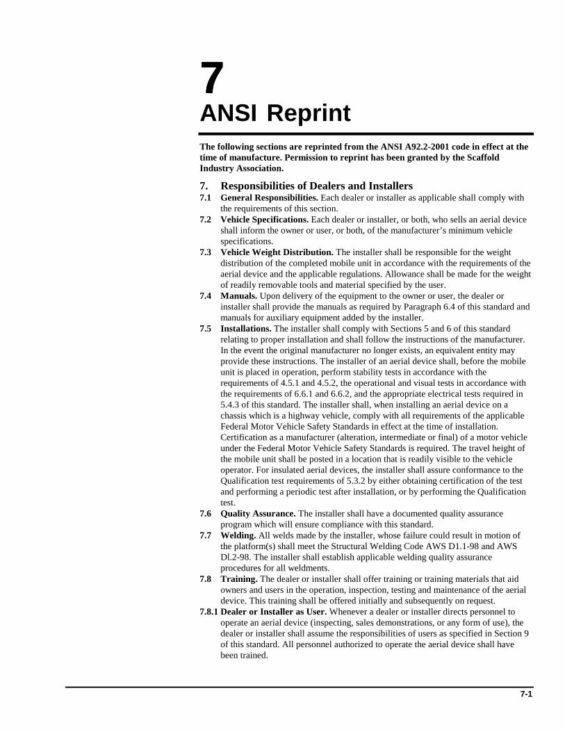
7-1
7777 ANSI Reprint The following sections are reprinted from the ANSI A92.2-2001 code in effect at the time of manufacture. Permission to reprint has been granted by the Scaffold Industry Association.
7. Responsibilities of Dealers and Installers 7.1 General Responsibilities. Each dealer or installer as applicable shall comply with
the requirements of this section. 7.2 Vehicle Specifications. Each dealer or installer, or both, who sells an aerial device
shall inform the owner or user, or both, of the manufacturer’s minimum vehicle specifications.
7.3 Vehicle Weight Distribution. The installer shall be responsible for the weight distribution of the completed mobile unit in accordance with the requirements of the aerial device and the applicable regulations. Allowance shall be made for the weight of readily removable tools and material specified by the user.
7.4 Manuals. Upon delivery of the equipment to the owner or user, the dealer or installer shall provide the manuals as required by Paragraph 6.4 of this standard and manuals for auxiliary equipment added by the installer.
7.5 Installations. The installer shall comply with Sections 5 and 6 of this standard relating to proper installation and shall follow the instructions of the manufacturer. In the event the original manufacturer no longer exists, an equivalent entity may provide these instructions. The installer of an aerial device shall, before the mobile unit is placed in operation, perform stability tests in accordance with the requirements of 4.5.1 and 4.5.2, the operational and visual tests in accordance with the requirements of 6.6.1 and 6.6.2, and the appropriate electrical tests required in 5.4.3 of this standard. The installer shall, when installing an aerial device on a chassis which is a highway vehicle, comply with all requirements of the applicable Federal Motor Vehicle Safety Standards in effect at the time of installation. Certification as a manufacturer (alteration, intermediate or final) of a motor vehicle under the Federal Motor Vehicle Safety Standards is required. The travel height of the mobile unit shall be posted in a location that is readily visible to the vehicle operator. For insulated aerial devices, the installer shall assure conformance to the Qualification test requirements of 5.3.2 by either obtaining certification of the test and performing a periodic test after installation, or by performing the Qualification test.
7.6 Quality Assurance. The installer shall have a documented quality assurance program which will ensure compliance with this standard.
7.7 Welding. All welds made by the installer, whose failure could result in motion of the platform(s) shall meet the Structural Welding Code AWS D1.1-98 and AWS Dl.2-98. The installer shall establish applicable welding quality assurance procedures for all weldments.
7.8 Training. The dealer or installer shall offer training or training materials that aid owners and users in the operation, inspection, testing and maintenance of the aerial device. This training shall be offered initially and subsequently on request.
7.8.1 Dealer or Installer as User. Whenever a dealer or installer directs personnel to operate an aerial device (inspecting, sales demonstrations, or any form of use), the dealer or installer shall assume the responsibilities of users as specified in Section 9 of this standard. All personnel authorized to operate the aerial device shall have been trained.

XLB-4232 DC
7-2
8. Responsibilities of Owners 8.1 General Responsibilities. Each owner shall comply with the requirements of this
section. The following responsibilities pertain to the owner’s inspection, testing, maintenance, modification, training, and transfer of ownership. These activities shall be performed by qualified person(s).
8.2 Inspection and Testing Classifications. 8.2.1 Initial Inspection and Test. Prior to initial use, all new or modified mobile units
shall be inspected and tested to ensure compliance with the provisions of this standard. Verification by the manufacturer, the installer or an equivalent entity(s), meets this requirement.
8.2.2 Regular Inspection and Tests. The inspection procedure for mobile units is divided into two classifications based upon the intervals at which inspections and tests shall be performed. Intervals shall be set by the owner in accordance with the manufacturer’s recommendations. Such intervals are dependent upon component function and exposure to wear, deterioration and other agents which adversely affect component life. Two classifications are designated:
(1) Frequent Inspection and Test: Daily to monthly intervals. (2) Periodic Inspection and Test: One to twelve month intervals. 8.2.3 Frequent Inspection and Test. Items determined by the owner in accordance with
the manufacturer’s recommendations for each specific aerial device shall be inspected for defects. The following tests and inspections shall be performed by the operator once daily, prior to first use:
(1) Operating controls and associated mechanisms for conditions interfering with proper operation.
(2) Visual and audible safety devices for malfunction. (3) Hydraulic or pneumatic systems for observable deterioration or excessive
leakage. (4) Fiberglass and other insulating components for visible damage or
contamination. (5) Missing or illegible operational and instructional markings. (6) Electrical systems of/or related to the aerial device for malfunction, signs of
excessive deterioration, dirt and moisture accumulation. (7) Visual inspection of bolts, pins, and other fasteners for loose, deformed or
missing fasteners and other locking devices. Any suspected items shall be carefully examined or tested and a determination made by a qualified person as to whether they constitute a safety hazard. All unsafe items shall be replaced or repaired before use.
8.2.4 Periodic Inspection or Test. An inspection of the mobile unit shall be performed at the intervals defined in 8.2.2 depending upon its activity, severity of service, and environment, or as specifically indicated below. (These inspections shall include the requirements of 8.2.3):
(1) Structural members for deformation, cracks or corrosion (2) Parts, such as pins, bearings, shafts, gears, rollers, locking devices, chains,
chain sprockets, wire and synthetic ropes, and sheaves for wear, cracks or distortion.
(3) Hydraulic and pneumatic relief valve settings. (4) Hydraulic system for proper oil level. (5) Hydraulic and pneumatic fittings, hoses, and tubing for evidence of leakage,
abnormal deformation or excessive abrasion. (6) Compressors, pumps, motors, and generators for loose fasteners, leaks,
unusual noises or vibrations, loss of operating speed, and excessive heating. (7) Hydraulic and pneumatic valves for malfunction and visible cracks in the
external valve housing, leaks, and sticking spools. (8) Visually inspect any vacuum prevention systems and verify function of such
systems on Category “A” aerial devices. (9) Hydraulic and pneumatic cylinders and holding valves for malfunction and
visible damage.
7 — ANSI REPRINT
7-3
(10) Hydraulic and pneumatic filters for cleanliness and the presence of foreign material in the system indicating other component deterioration.
(11) Electrical systems and components for deterioration or wear including those not readily visible on a frequent inspection.
(12) Performance test of all boom movements. (13) Condition and tightness of bolts and other fasteners. (14) Welds, as specified by the manufacturer. (15) Legible and proper identification, operational, and instructional markings.
(16) If the aerial device is rated as an insulated device, the electrical insulating components and system(s) shall be thoroughly inspected for lack of cleanliness and other conditions that compromise insulation. Then these components and system(s) shall be tested for compliance with the rating of the aerial device in accordance with one of the applicable methods and procedures as outlined in section 5.4.3 of this standard:
(a) If the aerial device is used for AC bare-hand work, the unit shall undergo a 60 Hz test as shown in Table 2 at least every three years;
(b) If the aerial device is used for DC bare-hand work, the unit shall undergo a DC test as shown in Table 2 at least every three years;
(c) After repair or modification of any component that crosses the insulating system(s), or the repair or replacement of an insulating component(s), the unit shall be dielectrically tested in accordance with section 5.4.3;
(d) An insulated replacement boom shall be tested to insure conformance to 5.3.3 by the supplier;
(e) Bare-hand work units shall be tested as shown in Table l after any major repair to the insulated boom or any insulated boom replacement. Any suspected items shall be carefully examined or tested and a determination made by a qualified person as to whether they constitute a safety hazard. All unsafe items shall be replaced or repaired before use.
8.3 Inspection and Test Records. (l) Items to be inspected shall be designated to the operator or other authorized
person making frequent inspections. Records of frequent inspections need not be made. However, where a safety hazard is found, it shall be reported in writing to a person responsible for the corrective action and that report and a record of the correction shall be maintained for five years, or as required by applicable regulations.
(2) Written, dated and signed reports and records shall be made of periodic inspections and tests and retained for a period of five years or as required by applicable regulations.
8.4 Maintenance. Maintenance and frequency of maintenance shall be determined by the owner in accordance with the manufacturer’s recommendations. Welding repairs of components or welds, designated as critical in the manufacturers manual, shall be made in accordance with the manufacturers recommendations. Should the original manufacturer no longer exist an equivalent entity may determine the required procedure.
8.4.1 Maintenance Training. The owner shall train their maintenance personnel in inspection and maintenance of the aerial device in accordance with the manufacturer’s recommendations and Section 8 of this standard.
8.5 Modifications. No modifications or additions which affect the stability, mechanical, hydraulic, or electrical integrity or the safe operation of the aerial device shall be made without the written approval of the manufacturer. If such modifications or changes are made, the capacity, operation, and maintenance instruction markings shall be changed accordingly. In no case shall the safety factors be reduced below those specified in this standard or below the manufacturers design safety factors, whichever are greater. Should the original manufacturer no longer exist, an equivalent entity may approve required modification.
8.6 Weight Distribution. Changes in loading or additions made to the mobile unit after the final acceptance that affect weight distribution shall meet applicable regulations
XLB-4232 DC
7-4
by governmental agencies. In no case shall axle loads of the fully loaded vehicle exceed the Gross Axle Weight Ratings (GAWR) assigned by the manufacturer. Note: Any change in weight distribution may adversely affect stability.
8.7 Transfer of Ownership. When a change in ownership of an aerial device occurs, it shall be the responsibility of the seller to provide the manufacturer's manual(s) for that aerial device to the purchaser. It is the responsibility of the purchaser to notify the manufacturer of the unit model and serial number and the name and address of the new owner within 60 days.
8.8 Markings. The markings on the aerial device shall not be removed, defaced, or altered. All missing or illegible markings shall be promptly replaced.
8.9 Parts. When parts or components are replaced they shall be identical in specification and function to the original aerial device parts or components or shall provide an equal or greater factor of safety.
8.10 Safety Bulletins. Owners shall comply with safety related bulletins as received from the manufacturer, dealer or installer.
8.11 Manuals. The owner shall insure that the operating manual(s) is stored on the mobile unit.
8.12 Training, Retraining, and Familiarization of Operators. 8.12.1 Owner as a Renter or Lessor. When an owner functions as a renter or lessor he
shall have the same responsibilities as specified under Section 11 of this standard. 8.12.2 General Training. Only personnel who have received general instructions
regarding the inspection, application and operation of aerial devices, including recognition and avoidance of hazards associated with their operation, shall operate an aerial device. Such items covered shall include, but not necessarily be limited to, the following issues and requirements:
(1) The purpose and use of manuals. (2) That operating manuals are an integral part of the aerial device and must be
properly stored on the vehicle when not in use. (3) A pre-start inspection.
(4) Responsibilities associated with problems or malfunctions affecting the operation of the aerial device.
(5) Factors affecting stability. (6) The purpose of placards and decals. (7) Workplace inspection. (8) Applicable safety rules and regulations, such as Part 4, ANSI C2-1997,
National Electrical Safety Code (applies to utility workers as defined in ANSI C2). The above standard is an example; other industries using aerial devices have safety rules pertinent to that industry.
(9) Authorization to operate. (10) Operator warnings and instructions.
(11) Actual operation of the aerial device. Under the direction of a qualified person, the trainee shall operate the aerial device for a sufficient period of time to demonstrate proficiency in the actual operation of the aerial device.
(12) Proper use of personal fall protection equipment 8.12.3 Retraining. The operator shall be retrained, when so directed by the user, based
on the user’s observation and evaluation of the operator. 8.12.4 Familiarization. When an operator is directed to operate an aerial device he/she is
not familiar with, the operator, prior to operating, shall be instructed regarding the following items and issues :
(1) The location of the manuals. (2) The purpose and function of all controls. (3) Safety devices and operating characteristics specific to the aerial device.
7 — ANSI REPRINT
7-5
9. Responsibility of Users. 9.1 General Responsibilities. Each User shall comply with the requirements of this
section. 9.2 Personnel. Only trained and authorized personnel shall be permitted to operate the
aerial device. 9.3 Training, Retraining, and Familiarization of Operators. 9.3.1 General Training. Only personnel who have received general instructions
regarding the inspection, application and operation of aerial devices, including recognition and avoidance of hazards associated with their operation, shall operate an aerial device. Such items covered shall include, but not necessarily be limited to, the following issues and requirements:
(1) The purpose and use of manuals. (2) That operating manuals are an integral part of the aerial device and must be
properly stored on the vehicle when not in use. (3) A pre-start inspection. (4) Responsibilities associated with problems or malfunctions affecting the
operation of the aerial device. (5) Factors affecting stability.
(6) The purpose of placards and decals. (7) Workplace inspection. (8) Applicable safety rules and regulations, such as Part 4, ANSI C2-1997,
National Electrical Safety Code. (applies to utility workers as defined in ANSI C2). The above standard is an example; other industries using aerial devices have safety rules pertinent to that industry.
(9) Authorization to operate. (10) Operator warnings and instructions.
(11) Actual operation of the aerial device. Under the direction of a qualified person, the trainee shall operate the aerial device for a sufficient period of time to demonstrate proficiency in the actual operation of the aerial device.
(12) Proper use of personal fall protection equipment 9.3.2 Retraining. The operator shall be retrained, when so directed by the user, based on
the user’s observation and evaluation of the operator. 9.3.3 Familiarization. When an operator is directed to operate an aerial device he/she is
not familiar with, the operator, prior to operating, shall be instructed regarding the following items and issues:
(1) The location of the manuals. (2) The purpose and function of all controls. (3) Safety devices and operating characteristics specific to the aerial device. 9.4 Application. The employer and assigned operator shall insure that the aerial device
is used only for intended applications as defined in the operating manual, and that recognized safety practices are observed.
9.5 Mobile Operation. Before and during driving, the driver shall: (1) Avoid traveling on any surface that adversely affects vehicle stability. (2) Maintain a safe distance from obstacles and overhead lines. (3) Maintain communications between the driver and the operator. (4) Under all travel conditions, the driver shall limit travel speed in accordance
with conditions of the ground surface, congestion, and slope. 9.6 Alterations. Altering or disabling of safety devices, guards, or interlocks if so
equipped shall be prohibited. 9.7 Bare-Hand Work. For bare-hand work, a Category “A” aerial device shall be used. 9.8 Lower Controls. The lower controls of aerial devices shall not be used for
continuous operation with personnel in the platform. 10. Responsibilities of Operators 10.1 General Responsibilities. Each operator shall comply with the requirements of this
section.

XLB-4232 DC
7-6
10.2 Operation. During operation of the aerial device all platform occupants shall use appropriate fall protection connected to the aerial device at the platform position.
10.3 Work Platform. The operator shall not use railings, planks, ladders or any other device in or on the work platform for achieving additional working height or reach.
10.4 Brakes. The vehicle parking brake(s) shall be set at all times that the boom is elevated except when the aerial device is being used in accordance with 9.5.
10.5 Loading. Any loading which includes a horizontal load shall be avoided unless the mobile unit is designed for that application.
10.6 Observations. Observations during operation for any defects shall be conducted on an ongoing basis.
10.6.1 Pre-start Inspection. Items determined by the owner in accordance with the manufacturer’s recommendations for each specific aerial device shall be inspected for defects prior to each day’s operation. The following tests and inspections shall be performed by the operator once daily, prior to first use:
(1) Operating controls and associated mechanisms for conditions interfering with proper operation.
(2) Visual and audible safety devices for malfunction. (3) Hydraulic or pneumatic systems for observable deterioration or excessive
leakage. (4) Fiberglass and other insulating components for visible damage or
contamination. (5) Missing or illegible operational and instructional markings. (6) Electrical systems of/or related to the aerial device for malfunction, signs of
excessive deterioration, dirt and moisture accumulation. (7) Visual inspection of bolts, pins, and other fasteners for loose, deformed or
missing fasteners and other locking devices. Any suspected items shall be carefully examined or tested and a determination made by a qualified person as to whether they constitute a safety hazard. All unsafe items shall be replaced or repaired before use.
10.7 Worksite. Before the aerial device is used the worksite shall be surveyed for hazards such as:
(1) Untamped earth fills. (2) Ditches. (3) Dropoffs and floor obstructions. (4) Debris. (5) Overhead obstructions and electrical conductors. (6) Weather conditions. (7) Presence of unauthorized persons. 10.8 Precautions. Before and during each use the operator shall: (1) Check for overhead obstructions and electrical conductors. (2) Insure that the load on the platform and/or load lifting devices are in
accordance with the manufacturer's rated capacity. (3) Insure that outriggers and stabilizers are used if the manufacturer's
instructions require their use. (4) Insure that guardrails are properly installed, and the gates are closed. (5) Use outrigger pads when necessary to provide firm footing. 10.9 Mobile Operation. Before engaging in mobile operation the operator shall
determine that the aerial device is specifically designed for mobile operation. 10.10 Personnel. Only trained and authorized personnel shall be permitted to operate the
aerial device. 10.11 Training, Retraining, and Familiarization of Operators. 10.11.1 General Training. Only personnel who have received general instructions
regarding the inspection, application and operation of aerial devices, including recognition and avoidance of hazards associated with their operation, shall operate an aerial device. Such items covered shall include, but not necessarily be limited to, the following issues and requirements:
(1) The purpose and use of manuals.
7 — ANSI REPRINT
7-7
(2) That operating manuals are an integral part of the aerial device and must be properly stored on the vehicle when not in use.
(3) A pre-start inspection. (4) Responsibilities associated with problems or malfunctions affecting the
operation of the aerial device. (5) Factors affecting stability. (6) The purpose of placards and decals. (7) Workplace inspection.
(8) Applicable safety rules and regulations, such as Part 4, ANSI C2-1997, National Electrical Safety Code (applies to utility workers as defined in ANSI C2). The above standard is an example; other industries using aerial devices have safety rules pertinent to that industry.
(9) Authorization to operate. (10) Operator warnings and instructions. (11) Actual operation of the aerial device. Under the direction of a qualified
person, the trainee shall operate the aerial device for a sufficient period of time to demonstrate proficiency in the actual operation of the aerial device.
(12) Proper use of personal fall protection equipment 10.11.2 Retraining. The operator shall be retrained, when so directed by the user, based
on the user’s observation and evaluation of the operator. 10.11.3 Familiarization. When an operator is directed to operate an aerial device he/she
is not familiar with, the operator, prior to operating, shall be instructed regarding the following items and issues:
(1) The location of the manuals. (2) The purpose and function of all controls. (3) Safety devices and operating characteristics specific to the aerial device. 11. Responsibilities of Renters, Lessors or Lessees 11.1 General Responsibilities. Each renter or lessor or lessee shall comply with the
requirements of the applicable section or sections below. 11.1.1 Lessor or Lessee as Dealer or Installer. When a lessor or lessee uses the aerial
device as a dealer or installer he shall have the same responsibilities as specified under Section 7 of this standard.
11.1.2 Lessor or Lessee as Owner. When a lessor or lessee uses the aerial device as an owner he shall have the same responsibilities as specified under Section 8 of this standard.
11.1.3 Lessor or Lessee as User. When a lessor or lessee uses the aerial device as a user he shall have the same responsibilities as specified under Section 9 of this standard.
11.1.4 Lessor or Lessee as Operator. When a lessor or lessee uses the aerial device as an operator he shall have the same responsibilities as specified under Section 10 of this standard.
11.2 Ownership Duties. The renter or lessor shall carry out the duties of ownership specified in this standard which are not assigned to the renting entity or lessee as the user.
11.3 Obligations. Upon delivery each renter or lessor of an aerial device shall provide the operators manual and the ANSI/SIA A92.2-xxxx Manual of Responsibilities for dealers, owners, users, operators, lessors and lessees of Vehicle Mounted Elevating and Rotating Aerial Devices. These manuals shall be stored on the mobile unit.
11.4 Training. The renter or lessor shall offer training or training materials that aid the renting entity or lessee in the operation, inspection, testing and maintenance of the aerial device. This training shall be offered initially and subsequently on request.
11.4.1 General training. Only personnel who have received general instructions regarding the inspection, application and operation of aerial devices, including recognition and avoidance of hazards associated with their operation, shall
XLB-4232 DC
7-8
operate an aerial device. Such items covered shall include, but not necessarily be limited to, the following issues and requirements:
(1) The purpose and use of manuals. (2) That operating manuals are an integral part of the aerial device and must
be properly stored on the vehicle when not in use. (3) A pre-start inspection. (4) Responsibilities associated with problems or malfunctions affecting the
operation of the aerial device. (5) Factors affecting stability. (6) The purpose of placards and decals. (7) Workplace inspection. (8) Applicable safety rules and regulations, such as Part 4, ANSI C2-1997,
National Electrical Safety Code (applies to utility workers as defined in ANSI C2). The above standard is an example; other industries using aerial devices have safety rules pertinent to that industry.
(9) Authorization to operate. (10) Operator warnings and instructions. (11) Actual operation of the aerial device. Under the direction of a qualified
person, the trainee shall operate the aerial device for a sufficient period of time to demonstrate proficiency in the actual operation of the aerial device.
(12) Proper use of personal fall protection equipment 11.4.2 Familiarization. When an operator is directed to operate an aerial device he/she is
not familiar with, the operator, prior to operating, shall be instructed regarding the following items and issues:
(1) The location of the manuals. (2) The purpose and function of all controls. (3) Safety devices and operating characteristics specific to the aerial device. 11.5 Communications. In the event the manufacturer or installer provides the renter or
lessor manuals, bulletins, or other materials for the information of the user of an aerial device, the renter or lessor shall pass them on to the user without any undue delay.
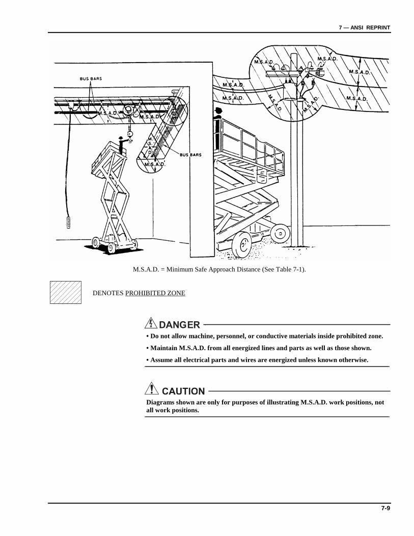
7 — ANSI REPRINT
7-9
M.S.A.D. = Minimum Safe Approach Distance (See Table 7-1).
• Do not allow machine, personnel, or conductive materials inside prohibited zone.
• Maintain M.S.A.D. from all energized lines and parts as well as those shown.
• Assume all electrical parts and wires are energized unless known otherwise.
Diagrams shown are only for purposes of illustrating M.S.A.D. work positions, not all work positions.
DENOTES PROHIBITED ZONE
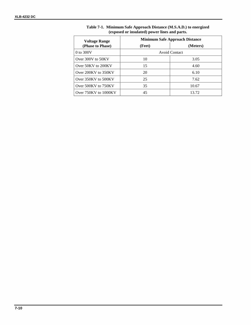
XLB-4232 DC
7-10
Table 7-1. Minimum Safe Approach Distance (M.S.A.D.) to energized (exposed or insulated) power lines and parts.
Minimum Safe Approach Distance Voltage Range (Phase to Phase) (Feet) (Meters)
0 to 300V Avoid Contact Over 300V to 50KV 10 3.05 Over 50KV to 200KV 15 4.60 Over 200KV to 350KV 20 6.10 Over 350KV to 500KV 25 7.62 Over 500KV to 750KV 35 10.67 Over 750KV to 1000KV 45 13.72


125 Taylor Parkway Archbold, OH 43502 Phone (419) 445-9675 (800) 527-5333 Fax (419) 445-0367