XII. LASER APPLICATIONS
20
XII. LASER APPLICATIONS Academic Research Staff Prof. S. Ezekiel Graduate Students R. E. Grove T. J. Ryan J. P. Sullivan L. A. Hackel J. R. Sneed F'. Y-F. \u P. D. Henshaw D. G. Youmans RESEARCH OBJECTIVES Our interest is primarily in the application of lasers to a variety of measurement problems. In certain cases, the available lasers are not very suitable and considerable research has to be done to improve the laser performance. Several projects are in progress. 1. Laser Frequency Stabilization The motivation for this work stems from the need for a long-term frequency stabi- lized laser in the precision measurement of length, i. e. , length standards. Such a laser would find applications in earth-strain seismometry, in optical communication, and in fundamental measurements, in particular, those related to experimental relativity. The task at present is to stabilize the frequency of the 5145 A argon ion laser. The stabilization scheme employs, as an absolute frequency reference, a resonance absorp- tion line, observed in a molecular beam of iodine. The absorption is measured by the resonance fluorescence induced by the laser in the molecular beam. Such an absorption line is an ideal reference element because of the isolated and unperturbed conditions in the beam. Moreover, since the molecular beam can be oriented at right angles to the laser beam, the width of the iodine resonance is limited to its natural width, which is inferred to be 100 klz from lifetime measurements. Preliminary experiments indicate that it should be possible to stabilize the frequency of the laser to one part in 1013 Thus far we have achieved a stability of 2 parts in 1011 2. High-Resolution Spectroscopy Using Molecular Beams We are investigating the use of molecular beams for high-resolution spectroscopy. A single-frequency 5145 A argon laser that can be tuned linearly over 0. 05 A is used to induce resonance fluorescence in a molecular beam of iodine. The resolution that we have achieved is less than 2 X 10 -9 and is still limited by Doppler broadening attrib- utable to molecular beam geometry. The laser, in the scanning mode, is capable of a resolution of better than 2 X 10 - 1 , as has been demonstrated with the use of a Fabry- Perot interferometer. 3. Single-Frequency cw Dye Laser Continuous dye lasers offer the possibility of having a laser line of narrow spectral This work is supported by the U. S. Air Force -Office of Scientific Research(Con- tract F44620-71-C-0051) and by the Joint Services Electronics Programs (U. S. Army, U. S. Navy, U. S. Air Force) under Contract DAAB07 -71-C-0300. QPR No. 108
Transcript of XII. LASER APPLICATIONS
XII. LASER APPLICATIONS
Academic Research Staff
Prof. S. Ezekiel
Graduate Students
R. E. Grove T. J. Ryan J. P. SullivanL. A. Hackel J. R. Sneed F'. Y-F. \uP. D. Henshaw D. G. Youmans
RESEARCH OBJECTIVES
Our interest is primarily in the application of lasers to a variety of measurementproblems. In certain cases, the available lasers are not very suitable and considerableresearch has to be done to improve the laser performance. Several projects are inprogress.
1. Laser Frequency Stabilization
The motivation for this work stems from the need for a long-term frequency stabi-lized laser in the precision measurement of length, i. e. , length standards. Such a laserwould find applications in earth-strain seismometry, in optical communication, and infundamental measurements, in particular, those related to experimental relativity.
The task at present is to stabilize the frequency of the 5145 A argon ion laser. Thestabilization scheme employs, as an absolute frequency reference, a resonance absorp-tion line, observed in a molecular beam of iodine. The absorption is measured by theresonance fluorescence induced by the laser in the molecular beam. Such an absorptionline is an ideal reference element because of the isolated and unperturbed conditions inthe beam. Moreover, since the molecular beam can be oriented at right angles to thelaser beam, the width of the iodine resonance is limited to its natural width, which isinferred to be 100 klz from lifetime measurements. Preliminary experiments indicate
that it should be possible to stabilize the frequency of the laser to one part in 1013 Thus
far we have achieved a stability of 2 parts in 1011
2. High-Resolution Spectroscopy Using Molecular Beams
We are investigating the use of molecular beams for high-resolution spectroscopy.
A single-frequency 5145 A argon laser that can be tuned linearly over 0. 05 A is usedto induce resonance fluorescence in a molecular beam of iodine. The resolution that
we have achieved is less than 2 X 10 - 9 and is still limited by Doppler broadening attrib-utable to molecular beam geometry. The laser, in the scanning mode, is capable of a
resolution of better than 2 X 10 - 1 , as has been demonstrated with the use of a Fabry-Perot interferometer.
3. Single-Frequency cw Dye Laser
Continuous dye lasers offer the possibility of having a laser line of narrow spectral
This work is supported by the U. S. Air Force -Office of Scientific Research(Con-tract F44620-71-C-0051) and by the Joint Services Electronics Programs (U. S. Army,U. S. Navy, U. S. Air Force) under Contract DAAB07 -71-C-0300.
QPR No. 108

(XII. LASER APPLICATIONS)
width anywhere in the visible spectrum. This type of laser has many applications, suchas spectroscopy and optical communication. The problem at present is that the dye laserfrequency is not very stable and the tuning of the frequency is not continuous.
We propose to investigate the sources of laser frequency jitter in a cw dye laser soas to achieve a narrow spectral line width and, in addition, to develop continuous tuning
schemes over limited ranges of approximately 1 A.
This research will complement our work in high-resolution spectroscopy usingmolecular beams.
4. Pulsed Ion Laser Holography
The purpose of this research is to investigate possibilities for generating pulsed,high-power, multicolor laser output by using a mixture of noble gases, such as argon,krypton and xenon for interferometric and holographic applications.
For pulsed color holography we need a laser that puts out 3 primary colors of equalintensity simultaneously in one short pulse. The research involves the study of excitationmechanisms in the presence of a mixture of noble gases to yield the desired laser output.
Aside from color holography, a hologram that is recorded in 2 colors (or frequen-cies) and reconstructed with only one color displays contour lines (lines of equal dis-tance from the hologram plate) superposed over the surface of the holographic image.The spacing between contour lines, which represents surface changes, is proportionalto the frequency separation of the two colors used in the recording of the hologram.
We would like to use this surface contour generation method, which requires only asingle short exposure, to study dynamic behavior of structures and materials and alsoto make growth measurement in biological subjects.
5. Flow Measurements
Laser Doppler techniques are being developed for measurement of both low-speedand high-speed fluid flow. A two-dimensional heterodyne scheme has been developedfor velocity measurement in vortex rings and in the wake of a model helicopter rotor.
For high-speed flow greater than 10 3 cm/s a scheme employing a Fabry-Perot cavity asa frequency discriminator is being investigated.
6. Closed-Loop Holographic Interferometry
We are exploring a new type of holographic interferometer. A diffuse object hasbeen locked (within tens of angstroms) to its holographically stored virtual image bymeans of a servo loop. This technique is being applied in the detection of subfringe defor-mations of diffuse surfaces and in measurements of small changes in surface thickness.
S. Ezekiel
QPR No. 108 100
(XII. LASER APPLICATIONS)
A. LASER MOLECULAR-BEAM TECHNIQUES FOR HIGTI-
RESOLUTION SPECTROSCOPY
USAF-OSR (Contract F44620-71-C-0051)
L. A. Hackel, D. G. Youmans, S. Ezekiel
A method employing a tunable single-frequency laser and a molecular beam has been
used to obtain a high-resolution optical spectrum of the hyperfine structure of 12. In
laser optical spectroscopy, the limiting factors are often Doppler and pressure broadening
of the resonance lines. Saturated absorption has recently become a popular means of
overcoming the Doppler effect.1 The molecular-beam technique, however, offers con-
trol over Doppler broadening and also lacks the pressure broadening and pressure shift
of the saturation techniques used for gas cells.
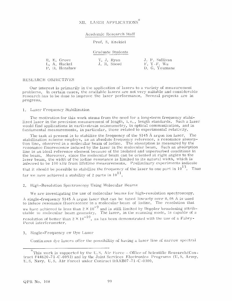
The experimental arrangement (Fig. XII-1) is similar to that used previously. A
single-frequency tunable 5145 A argon ion laser excites the I 2 molecular beam. The
induced fluorescence is detected by a photomultiplier. The excited transitions are the
12 MOLECULAR
BEAM
SINGLE-FREQUENCY APPARATUS
7145-A ARGON LASER CHOPPERI, BEAM
)ELECTRI(YSTALS
RAMP
Fig. XII-1. Schematic view of the apparatus.
hyperfine components of the P(13) (43-0) and R(15) (43-0) lines between the 1+(X) and3+ 127 g3 + (B) electronic states in 27 which fall within the bandwidth of the 5145 A laser.
Ou 2Single-frequency operation is obtained by using a composite cavity made up of two
cavities, one short and one long.4 A feedback loop with 1-kIlz bandwidth maintains the
coupling between the cavities. The laser frequency is scanned by changing the length of
QPR No. 108
(XII. LASER APPLICATIONS)
the short cavity by means of a piezoelectric crystal as shown in Fig. XII-1. In this locked
mode of operation, the system linearity is determined by the linear response of the crys-
tal and is not affected as much by the dispersion of the gain medium as it would be in an
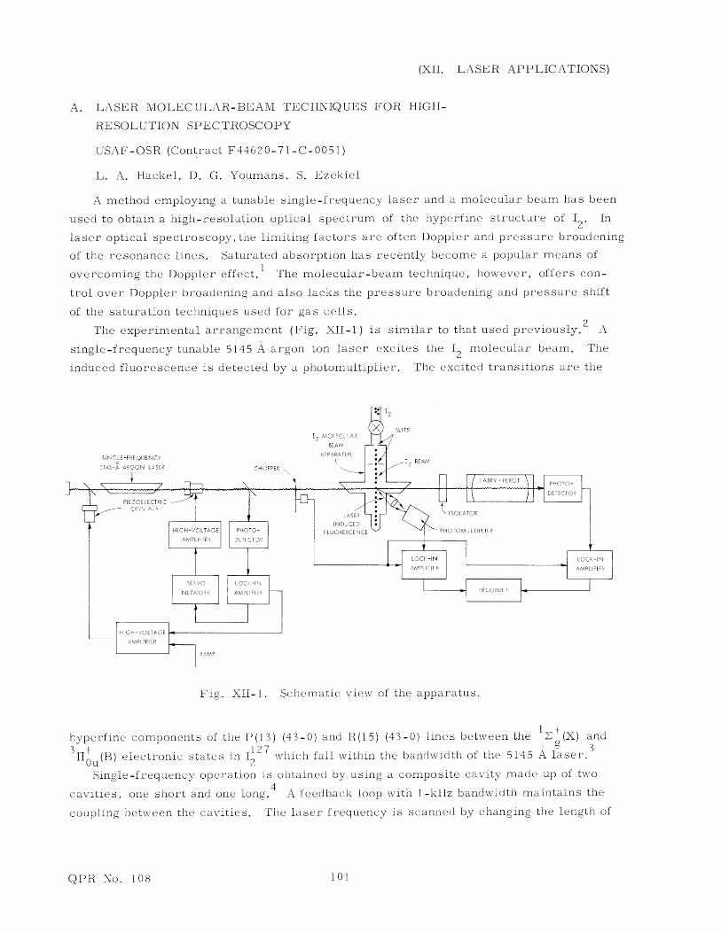
open-loop scan. Figure XII-2a shows a scan over a 1-MHz (FWMM) Fabry-Perot with
a free spectral range of 300 MHz. The data indicate that laser short-term stability is
better than 100 kHz.
The molecular beam apparatus, shown in Fig. XII-1, is a high-vacuum chamber into
which I2 molecules effuse through a narrow primary slit. A secondary slit, farther down,
collimates the beam. The degree of collimation is determined by the width of the slits
and the distance between them. The laser beam is chopped at 1 kHz. The 12 fluorescence
i- 4!
S(b)
Fig. XII-2. Simultaneous recording as a function of laser frequency.
(a) Transmission resonances of the Fabry-Perot inter-
ferometer (free spectral range 300 MHz).(b) Hyperfine structure of 12 molecular beam (T = 100 ms).
incident on a photomultiplier is synchronously detected with a lock-in amplifier. The
laser beam also excites the Fabry-Perot, and the fluorescence and Fabry-Perot data are
recorded simultaneously.
The measured width of the lines shown in Fig. XII-2b is typically 3 MHz. The slit
geometry dictated a Doppler width of 400 kHz. This contrasted sharply with lifetime
measurements in the beam which indicated a natural width of 100 kHz.
In an effort to check on the possibility of small-angle collisions in the beam appara-
tus, the primary slit was reduced by a factor of four, thereby reducing both the number
of molecules in the region between the slits and the possibility of collisions during the
transit through the primary slit. At the same time the secondary slit was widened to
QPR No. 108 102

(XII. LASER APPLICATIONS)
retain the same signal-to-noise ratio. In terms of slit geometry, the change resulted in
an increase in beam angle from one to two milliradians. With the new slit geometry the
resultant scan produced lines approximately 1. 5 MHz wide. A portion of this spectrum
is shown in Fig. XII-3. We shall try to observe the natural width of the 12 transition. In
Fig. XII-3.
Portion of 12 hyperfine structure showing
lines approximately 1. 5 MHz wide (T = 30 ms).
future experiments we shall employ narrower geometrical widths. The present resolution
puts an 800-kHz upper limit on the natural linewidth.
When a more intense and geometrically broadened 12 beam is used, other transitions,
weaker than the prominent ones, are uncovered. Figure XII-4 shows the derivative of
FREQUENCY-
Fig. XII-4. Derivative of '2 hyperfine structure showing existence
of weaker lines not clearly observable in Fig. XII-2b(T = 100 ms).
12 transitions excited in this manner. The weak lines are shown dispersed among thestronger transitions associated with the P(13) and R(15) lines.
Laser m6lecular-beam techniques are clearly useful in high-resolution optical spec-troscopy. Their application to laser frequency stabilization has already been demon-
strated. 5
References
1. P. H. Lee and M. S. Skolnick, Appl. Phys. Letters 10, 303 (1967); R. L. Bargerand J. L. Hall, Phys. Rev. Letters 22, 4 (1969); M. S. Sorem and A. L. Schawlow,Opt. Commun. 5, 148 (1972).
2. S. Ezekiel and R. Weiss, Phys. Rev. Letters 20, 91 (1968).2. S. Ezekiel and R. Weiss, Phys. Rev. Letters 20, 91 (1968).
QPR No. 108
.. .
103
(XII. LASER APPLICATIONS)
3. M. D. Levenson and A. L. Schawlow, Phys. Rev. A 6, 10 (1972).
4. P. W. Smith, IEEE J. Quant. Electronics, Vol. QE-1, No. 8, pp. 343-348, Novem-ber 1965.
5. T. J. Ryan, D. G. Youmans, L. A. Itackel, and S. Ezekiel, Appl. Phys. Letters 21,320 (1970).
B. MOLECULAR-BEAM STABILIZED ARGON LASER
USAF-OSR (Contract F44620-71 -C-0051)
D. G. Youmans, L. A. Ilackel, S. Ezekiel
We report the locking of the 5145 A argon ion laser to an 12 resonance observed in a
molecular beam. A molecular beam external reference is attractive because transitions
observed in the isolated conditions in the beam do not suffer frequency shifts caused by
collisions or collisional broadening and, if the molecular beam is excited orthogonally
by the laser, Doppler broadening can be virtually eliminated.
Resonance fluorescence induced in a molecular beam of iodine by a single-frequency1 127
5145 A argon ion laser has been reported previously. The 12 excited transitions are
the hyperfine components of the P(13) R(15) (43-0) lines between the f (X) and the3+ 2
IOu(B) electronic states falling within the Doppler width of the 5145 A laser.
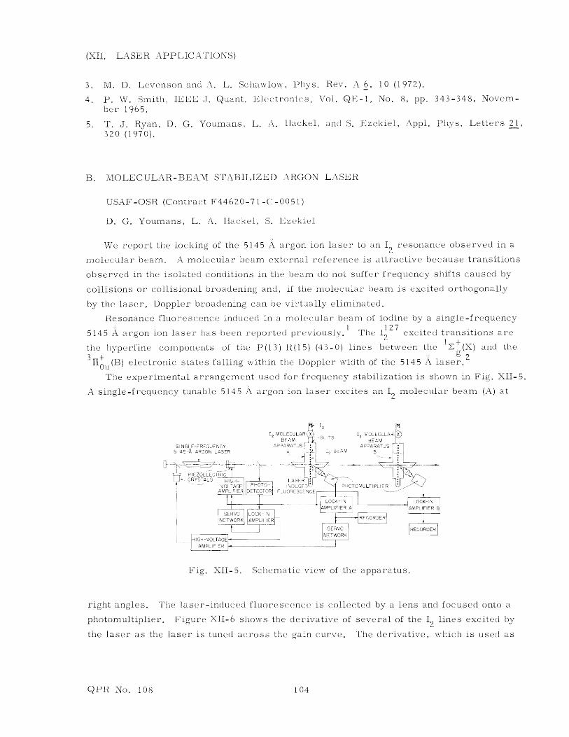
The experimental arrangement used for frequency stabilization is shown in Fig. XII-5.
A single-frequency tunable 5145 A argon ion laser excites an 12 molecular beam (A) at
2
I, MOLECULAR 'X I MOLECULAR XBEAM BEAM
SINGLE FREQUENCY APPARATUS APPARATUS F5145- ARGON LASER A
2 BEAM B
PIEZOELECTRICCRYSTALS Hi LASER
VOLTAGE PHCT INDUCED PHOTOMULTIPLIERAMPLIFIER TECTOR FLUORESCENCE
I JLOCK-1 N LOCK-INAMPLIFIER A AMPLIFIER B
SERVO REGORDER
AMPLIIEB
Fig. XII-5. Schematic view of the apparatus.
right angles. The laser-induced fluorescence is collected by a lens and focused onto a
photomultiplier. Figure XII-6 shows the derivative of several of the 12 lines excited by
the laser as the laser is tuned across the gain curve. The derivative, which is used as
QPR No. 108 104

(XII. LASER APPLICATIONS)
a frequency discriminant, is obtained by modulating the laser frequency and synchro-nously detecting the fluorescence signal in a lock-in amplifier. The laser frequency islocked to one of the 12 transitions, e. g., the second one from the left (Fig. XII-6).
-. 20 MHz
FREQUENCY-
Fig. XII-6. Derivative of 12 hyperfine structure observed in a
molecular beam (T = 30 ms).
Measurement of laser frequency stability, at present, is done by monitoring the frequencydiscriminant associated with an identical 12 transition that is excited by the stabilizedlaser in an independent molecular-beam apparatus (B) (Fig. XII-5).
Single-frequency laser operation is achieved by use of a composite cavity comprisingtwo coupled cavities, one short and one long, a method similar to that of Smith.3 A feed-back loop with a 1-kHz bandwidth maintains the coupling of the two cavities by locking thelong cavity to the short cavity. The laser frequency may thus be scanned smoothly acrossthe gain curve by linearly changing the length of the short cavity. This is accomplishedby applying a ramp voltage to the piezoelectric crystal in the short cavity. The argonlaser operates free from plasma oscillations. Techniques for suppressing plasma oscil-lations in our discharge-tube configuration have been reported previously. 4
Fig. XII-7.
Output of 1-MHz Fabry-Perot when the laser
is scanned at 4 X 10 - 5 s/MHz.
-5 M H--
The short-term jitter of the laser frequency was investigated with a scanning Fabry-Perot (Tropel Model 216) that has an instrument width of 1 MHz and a free spectral rangeof 300 MHz. Figure XII-7 shows the output of the Fabry-Perot when the laser frequencyis scanned at a rate of 4 X 10 - 5 s/MHz. The width of the Fabry-Perot resonance(Fig. XII-7) is identical with the instrument width and this puts an upper limit on laser
QPR No. 108
r
105
(XII. LASER APPLICATIONS)
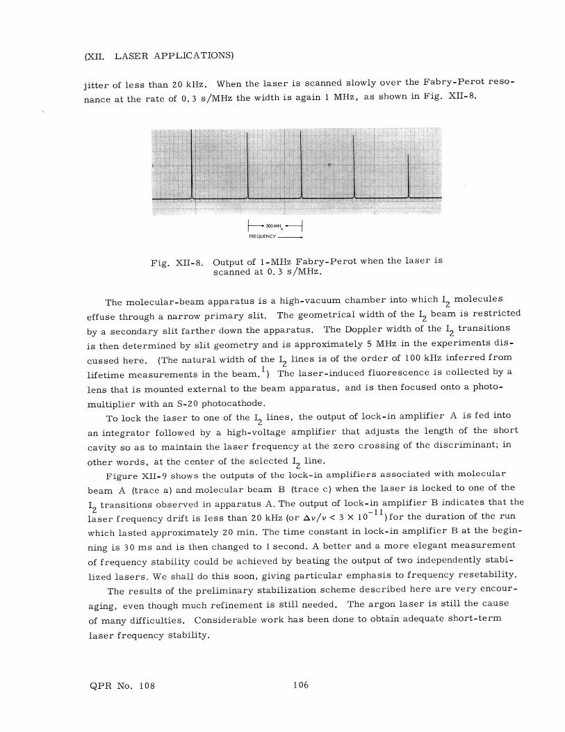
jitter of less than 20 kHz. When the laser is scanned slowly over the Fabry-Perot reso-
nance at the rate of 0. 3 s/MHz the width is again 1 MHz, as shown in Fig. XII-8.
:4 --I
S300MHzFREQUENCY
Fig. XII-8. Output of 1-MHz Fabry-Perot when the laser is
scanned at 0. 3 s/MHz.
The molecular-beam apparatus is a high-vacuum chamber into which 12 molecules
effuse through a narrow primary slit. The geometrical width of the 12 beam is restricted
by a secondary slit farther down the apparatus. The Doppler width of the 12 transitions
is then determined by slit geometry and is approximately 5 MHz in the experiments dis-
cussed here. (The natural width of the 12 lines is of the order of 100 kHz inferred from1
lifetime measurements in the beam. ) The laser-induced fluorescence is collected by a
lens that is mounted external to the beam apparatus, and is then focused onto a photo-
multiplier with an S-20 photocathode.
To lock the laser to one of the 12 lines, the output of lock-in amplifier A is fed into
an integrator followed by a high-voltage amplifier that adjusts the length of the short
cavity so as to maintain the laser frequency at the zero crossing of the discriminant; in
other words, at the center of the selected 12 line.
Figure XII-9 shows the outputs of the lock-in amplifiers associated with molecular
beam A (trace a) and molecular beam B (trace c) when the laser is locked to one of the
12 transitions observed in apparatus A. The output of lock-in amplifier B indicates that the
laser frequency drift is less than 20 kHz (or Av/v < 3 X 10- ) for the duration of the run
which lasted approximately 20 min. The time constant in lock-in amplifier B at the begin-
ning is 30 ms and is then changed to 1 second. A better and a more elegant measurement
of frequency stability could be achieved by beating the output of two independently stabi-
lized lasers. We shall do this soon, giving particular emphasis to frequency resetability.
The results of the preliminary stabilization scheme described here are very encour-
aging, even though much refinement is still needed. The argon laser is still the cause
of many difficulties. Considerable work has been done to obtain adequate short-term
laser frequency stability.
QPR No. 108
I -- L
106

(XII. LASER APPLICATIONS)
The use of a molecular-beam reference promises a high degree of long-term stability
and resetability of the laser frequency. The major drawback in this type of stabilization
LOCKTIME TELOCK
Fig. XII-9. Time recording of laser frequency drift.(a) Output of lock-in amplifier A.(b) Laser power.(c) Output of lock-in amplifier B.
T = 30 ms; later T = 1 s.Total elapsed time = 20 min.
is the nonorthogonality between laser beam and molecular beam, which causes a Doppler
shift. This Doppler shift, however, can be converted into a Doppler broadening by
reflecting the laser beam back on itself through the molecular-beam apparatus. A more
promising method for eliminating shifts caused by misalignment is to lock the laser to'
the saturated absorption dip at the center of the 12 transition in the beam. It would cer-
tainly be interesting to find out how a molecular beam reference would eventually compare5
with a saturated absorption reference in a gas cell, especially with respect to long-term
stability and resetability.
References
1. S. Ezekiel and R. Weiss, Phys. Rev. Letters 20, 91 (1968).
2. M. D. Levenson and A. L. Schawlow, Phys. Rev. A 6, 10 (1972).
3. P. W. Smith, IEEE J. Quant. Electronics, Vol. QE-1, p. 343, 1965.
4. D. C. Galehouse, U. Ingard, T. J. Ryan, and S. Ezekiel, Appl. Phys. Letters 18,13 (1971).
5. R. L. Barger and J. L. Hall, Phys. Rev. Letters 22, 4 (1969); J. L. Hall and R. L.Barger, Proc. Twenty-third Annual Symposium on Frequency Control, U. S. ArmyElectronics Command, Fort Monmouth, New Jersey, 1969.
QPR No. 108
I ~
107
(XII. LASER APPLICATIONS)
C. TWO-DIMENSIONAL LASER DOPPLER VELOCIMETER
Joint Services Electronics Programs (Contract DAAB07-71 -C -0300)
Partially supported by Naval Air Systems Command
J. P. Sullivan, S. Ezekiel
In a previous report preliminary data from a laser Doppler velocimeter (LDV)
capable of measuring two components of the velocity vector in a fluid flow were pre-
sented. 1 The present report gives a complete description of the LDV system, with
special emphasis on the data-processing equipment.
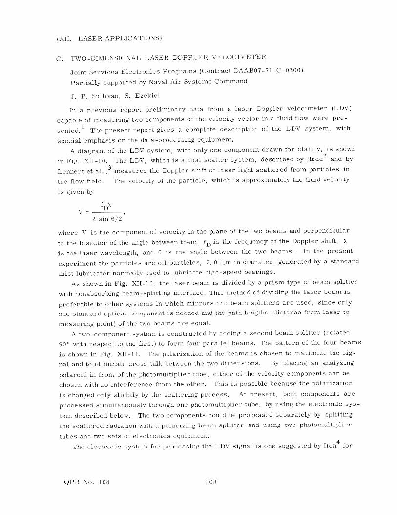
A diagram of the LDV system, with only one component drawn for clarity, is shown2
in Fig. XII-10. The LDV, which is a dual scatter system, described by Rudd and by
Lennert et al.,3 measures the Doppler shift of laser light scattered from particles in
the flow field. The velocity of the particle, which is approximately the fluid velocity,
is given by
V D
2 sin 0/2
where V is the component of velocity in the plane of the two beams and perpendicular
to the bisector of the angle between them, fD is the frequency of the Doppler shift, X
is the laser wavelength, and 0 is the angle between the two beams. In the present
experiment the particles are oil particles, 2. 0-m in diameter, generated by a standard
mist lubricator normally used to lubricate high-speed bearings.
As shown in Fig. XII-10, the laser beam is divided by a prism type of beam splitter
with nonabsorbing beam-splitting interface. This method of dividing the laser beam is
preferable to other systems in which mirrors and beam splitters are used, since only
one standard optical component is needed and the path lengths (distance from laser to
measuring point) of the two beams are equal.
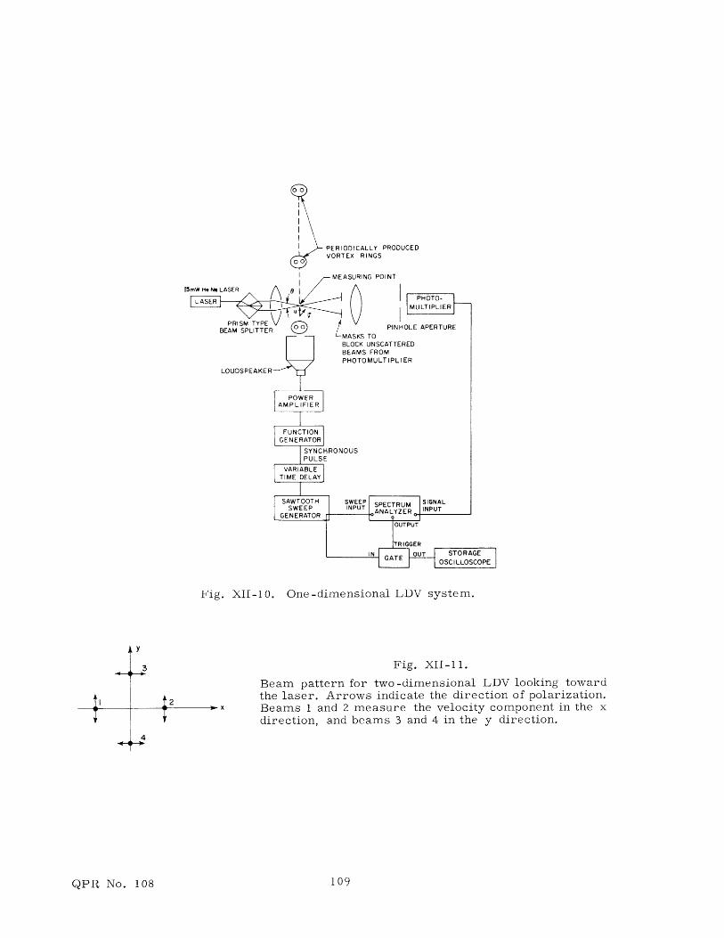
A two-component system is constructed by adding a second beam splitter (rotated
90' with respect to the first) to form four parallel beams. The pattern of the four beams
is shown in Fig. XII-11. The polarization of the beams is chosen to maximize the sig-
nal and to eliminate cross talk between the two dimensions. By placing an analyzing
polaroid in front of the photomultiplier tube, either of the velocity components can be
chosen with no interference from the other. This is possible because the polarization
is changed only slightly by the scattering process. At present, both components are
processed simultaneously through one photomultiplier tube, by using the electronic sys-
tem described below. The two components could be processed separately by splitting
the scattered radiation with a polarizing beam splitter and using two photomultiplier
tubes and two sets of electronics equipment.
The electronic system for processing the LDV signal is one suggested by Iten 4 for
QPR No. 108 108
00
PERIODICALLY PRODUCEDVORTEX RINGS
- R AQI IINJC P)IN T
Fig. XII-10. One-dimensional LDV system.
Fig. XII-11.
Beam pattern for two-dimensional LDV looking towardthe laser. Arrows indicate the direction of polarization.Beams 1 and 2 measure the velocity component in the xdirection, and beams 3 and 4 in the y direction.
QPR No. 108 109
(XII. LASER APPLICATIONS)
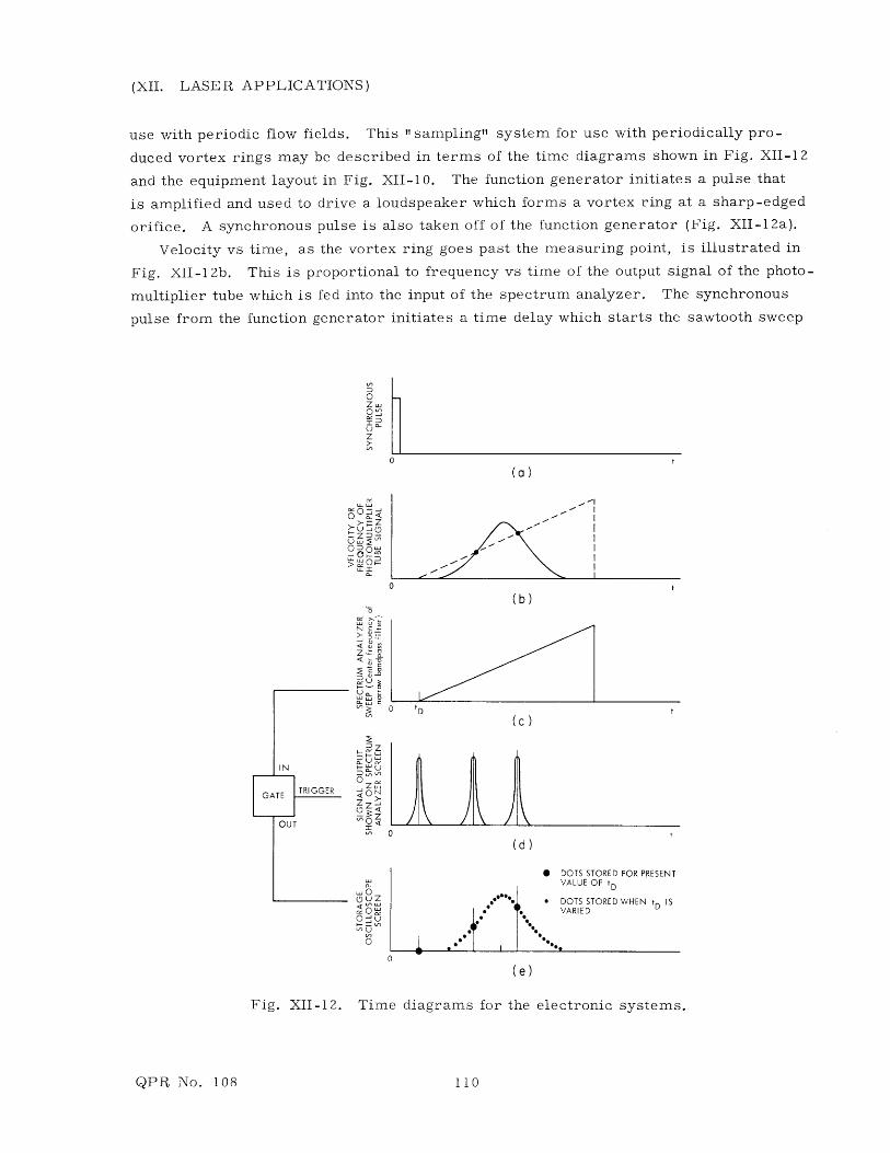
use with periodic flow fields. This "sampling" system for use with periodically pro-
duced vortex rings may be described in terms of the time diagrams shown in Fig. XII-12
and the equipment layout in Fig. XII-10. The function generator initiates a pulse that
is amplified and used to drive a loudspeaker which forms a vortex ring at a sharp-edged
orifice. A synchronous pulse is also taken off of the function generator (Fig. XII-12a).
Velocity vs time, as the vortex ring goes past the measuring point, is illustrated in
Fig. XII-12b. This is proportional to frequency vs time of the output signal of the photo-
multiplier tube which is fed into the input of the spectrum analyzer. The synchronous
pulse from the function generator initiates a time delay which starts the sawtooth sweep
O
~U-d5-ZDJ
O Do
0 0"
>a:
NO.-0
u~
N
(Da U
0oDW W
0©uz
0
,UZ< n0 W
0 U'
0"O
0 tD t(c
0
(d
0 DOTS STORED FOR PRESENTVALUE OF tD
oo*** * DOTS STORED WHEN tD IS*VARIED
(e)
Fig. XII-12. Time diagrams for the electronic systems.
QPR No. 108 110

Fig. XII-13.
Demodulationf = 500 kHzo
Af = 450 kHzfM = 33 Hz
Time scale =
of test signal.
10 MHz/cm.
U = -YO
V ZWX
32.0
U)24.0
U-
>- 16.0I-..
o 8.0
0-2.00 -1.00 0 1.00
DISTANCE , x (INCHES)
LDV
u 19.16FT/S
WYo19.75 FT/S
U LDV - to YO w 2.98%yo
Fig. XII-14. Linearity and velocity check by using a spinning disk.
QPR No. 108
LOMHz -
O.5MHz -
o -
111
(XII. LASER APPLICATIONS)
generator (Fig. XII-12c) for the spectrum analyzer after a time t D . The linear sawtooth
represents the center frequency of the narrow filter of the spectrum analyzer. When
the frequency from the photomultiplier tube is equal to the instantaneous frequency of
the narrow bandpass filter of the spectrum analyzer a pip will occur on the spectrum
analyzer face and at the spectrum analyzer output (Fig. XII-12d). This condition can
be determined by superposing Fig. XII-12c on Fig. XII-12b. The linear sawtooth is fed
to the input of a gate which is only opened when a pip occurs on the spectrum analyzer.
The output of the gate (in this case, 3 spots, see Fig. XII-12e) is stored on a storage
oscilloscope. The three spots correspond to a zero-frequency marker and 2 points on
the velocity vs time curve which we wish to determine. By varying the time delay, the
remaining points on the velocity curve can be stored.
The results of demodulating a test oscillator signal varying from 50 kHz to 950 kHz
at a rate of 33 Hz are shown in Fig. XII-13.
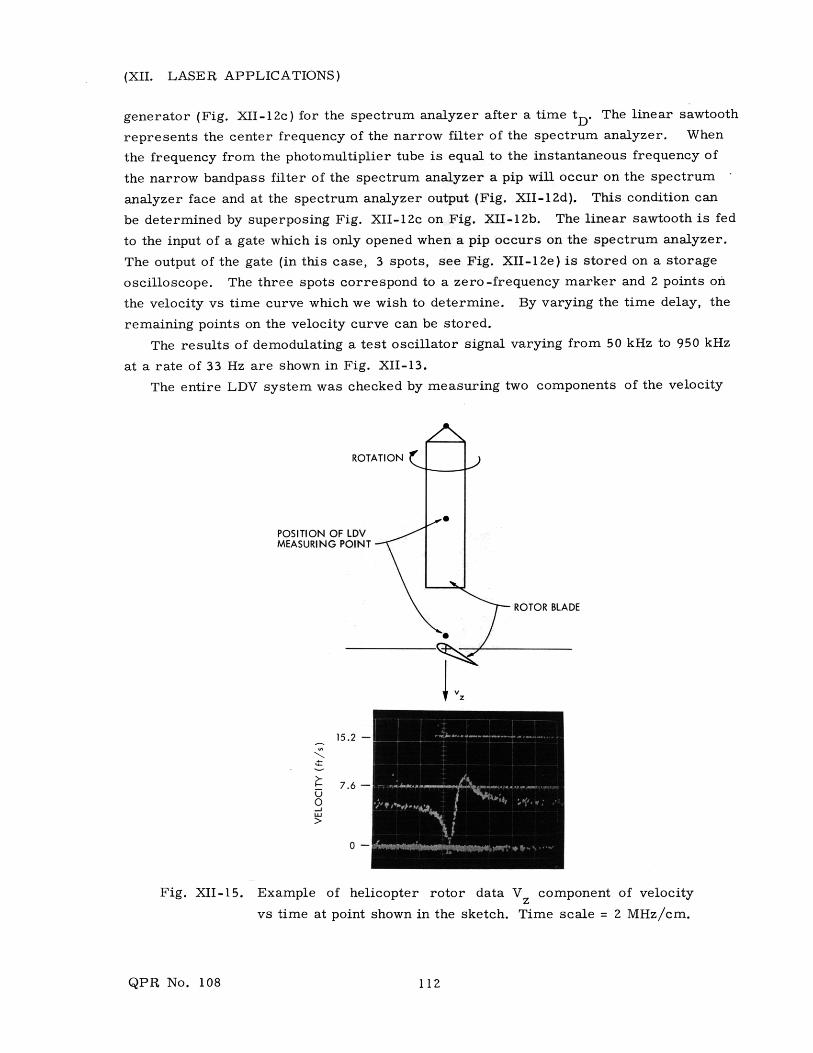
The entire LDV system was checked by measuring two components of the velocity
ROTATION (
POSITION OF LDVMEASURING POINT
. SROTOR BLADE
I V2
15.2 -
7.6 -
Fig. XII-15. Example of helicopter rotor data V z component of velocity
vs time at point shown in the sketch. Time scale = 2 MHz/cm.
QPR No. 108 112
(XII. LASER APPLICATIONS)
of a spinning disk as the disk was traversed across the measuring point. The x com-
ponent of velocity U = -wy should be a constant and the y component V = cox should vary
linearly as the disk moves in the x direction. The results of this check, shown in
Fig. XII-14, indicate that the linearity of the electronics system is excellent and that the
velocity error is within experimental error in determining the rpm of the disk. Theambiguity in determining the direction of U and V is demonstrated in Fig. XII-14. TheU component is always negative and the V component is negative for negative values
of X.
The two-component LDV system has been used for extensive velocity measurements
in periodically produced vortex rings and in the wake of a model helicopter rotor.
Examples of the data from vortex rings were given in our previous report.1
When the system is used for helicopter rotor measurements, the model rotor is
placed in the position of the vortex ring generator shown in Fig. XII-10, and a synchro-
nous signal from the rotating shaft is used to initiate the electronic data-processing
system.
An example of data from the rotor measurements is shown in Fig. XII-15. The
oscilloscope trace shows velocity vs time at a point half-way out and a little above the
rotor blade. The experimental curve of the Vz component of velocity shows the clas-
sical signature of a lifting airfoil.
References
1. Quarterly Progress Report No. 104, Research Laboratory of Electronics, M. I. T.,January 15, 1972, pp. 142-145.
2. M. J. Rudd, J. Phys. E 2, 55-58 (1969).
3. A. E. Lennert, E. B. Brayton, and F. L. Crossay, AEDC-TR-70-101, "SummaryReport of the Development of a Laser Velocimeter to Be Used in Arnold EngineeringDevelopment Center Wind Tunnels," July 1970.
4. P. Iten, Private communication.
D. MULTIPLE-FREQUENCY HOLOGRAPHY USING PULSED
ION LASERS
Joint Services Electronics Programs (Contract DAAB07-71-C-0300)
P. D. Henshaw, S. Ezekiel
The use of two-frequency holography to produce contour fringes on objects has been1-6well documented, but all schemes share a common difficulty in that the optics neces-
sary to produce the proper reconstruction geometry limit the system. Careful align-
ment is necessary to avoid poor fringe localization or even complete destruction of the
contours. We have developed a system in which alignment is not critical, fringe
QPR No. 108 113
(XII. LASER APPLICATIONS)
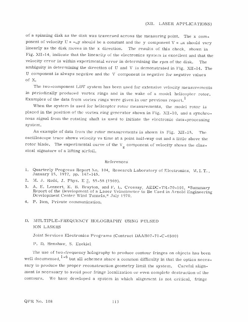
localization is guaranteed, and the contours may be viewed in white light. Because the
object and reference beams travel nearly the same distance, lasers with limited coher-
ence can be used to record the hologram. These advantages result from use of an
extremely simple recording and reconstruction geometry, which is shown in Fig. XII-16.
Let (x o , Yo, Z ) be an object point where the coordinates are defined relative to the
center of the hologram plate. Similarly, let the reference source be located at (xr, Yr'
z ). In reconstruction, let the reconstructing source be at (xc, Yc, Zc), and the image
point be at (xi, Yi, zi). For convenience we prefer the reference and reconstruction
HOLOGRAM PLATE(EMULSION FACING OBJECT)
OBJECT
LASER LIGHT (X, X 2
EXPANDING ANDCOLLIMATING OPTICS ORIGIN FOR ALL COORDINATES
(a)
OBERVER HOLOGRAM
IM
AGE
POINTSOURCE )(SUCH AS SLIDEPROJECTOR AND APERTURE)
(b)
Fig. XII-16. (a) Recording and (b) reconstruction geometry.
beams to have the same coordinates for all colors if a multicolor laser is used.
It can be shown that the image location (x i , Yi' zi) is given by1 1 1
1 1 1 + 1 (1)ci ro rr cc
X. x x x1 0 r + c (2)X z. X z 0\z X z
Yi o r cc (3)X z. X z z + zC i ro 0 rr c c
QPR No. 108 114

(XII. LASER APPLICATIONS)
By setting zr = z c = oo (using plane waves for reference and reconstruction), the mag-
nification M in the z direction becomesz
zi rM - r (4)
z z 0 k
which is equal to the ratio of the wavelengths used to record and reconstruct the holo-
gram.
Equation 2 can be rewritten
z X zx. =x --- x +- - x . (5)1 o z r k z cr c c
If several holograms are recorded at different wavelengths, then as z - 0, x. - x ando 1 0
all images coincide in the x and y directions, independent of the reconstruction wave -
length. This is exactly the requirement necessary for good contour fringes when using
two wavelengths. Figure XII-16a shows the method that we use to meet the require-
ments. The depth contours are spaced at Az = X2/ZAX, independent of the reconstruction
wavelength. 4 This means that the fringes can be viewed in white light with no blurring
of the contours. With the recording geometry shown in Fig. XII-1 6a we use a single
beam to supply both reference and object beams. The hologram itself acts as the beam
Fig. XII-17.
Hologram contour map of a silver dollar usingo
5353 A and 5396 A lines.
splitter, which means that only relative motion between the object and the hologram
plate will affect the holographic recording. This is relatively easy to eliminate by fixing
the plate to the object, thereby reducing the need for vibration isolation.
This recording geometry is ideal for pulsed holography, where the energy per pulse
is limited. In conventional hologram arrangements with two beams used, much of the
light scattered by the object is not collected by the hologram. In our case almost all
of the light reaches the hologram.
Several contour maps of coins have been made using the 5353 A and 5395 A lines
QPR No. 108
I __ _ _ _ _
MEMW
115

(XII. LASER APPLICATIONS)
from a pulsed xenon laser. The fringe spacing is 34 [m. Figure XII-17 shows a recon-
struction of a typical hologram in white light.
References
1. J. R. Varner, "Simplified Multiple-Frequency Holographic Contouring," Appl.Opt. 10, 212 (1971).
2. L. O. Heflinger and R. F. Wuerker, "Holographic Contouring via MultifrequencyLasers," Appl. Phys. Letters 15, 28 (1969).
3. W. Schmidt and A. F. Fercher, "Holographic Generation of Depth Contours Usinga Flash-Lamp-Pumped Dye Laser," Opt. Communs. 3, 363-365 (1971).
4. B. P. Hildebrand and K. A. Haines, "Multiple-Wavelength and Multiple-Source
Holography Applied to Contour Generation," J. Opt. Soc. Am. 57, 155 (1967).
5. J. S. Zelenka and J. R. Varner, "Multiple-Index Holographic Contouring," Appl.
Opt. 8, 1431 (1969).
6. J. S. Zelenka and J. R. Varner, "A New Method for Generating Depth Contours
Holographically," Appl. Opt. 7, 2107 (1968).
E. COHERENCE PROPERTIES OF A FLASH-LAMP-PUMPED
DYE AMPLIFIER
Joint Services Electronics Programs (Contract DAAB07-71-C-0300)
P. D. Henshaw, S. Ezekiel
The study of high-power ion lasers for multicolor holography has led us to investi-
gate the use of a dye cell pumped by a flash lamp as an amplifier. Our objective was
to combine the high gain of a flash-lamp-pumped dye with the relatively long coherence
length of a gas laser.
A pulsed xenon laser was used as the master oscillator. This laser appears to be
a good choice because high-power lines are available throughout the visible spectrum. 1 , 2
Other desirable characteristics are a short pulse, which is compatible with a flash-
lamp-pumped dye cell, and relatively narrow Doppler broadening attributable to the
large atomic weight of xenon.
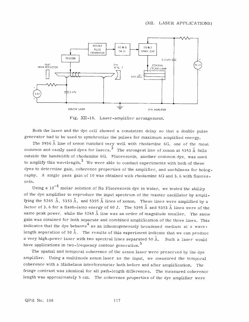
A block diagram of our apparatus is shown in Fig. XII-18. The xenon laser was
excited by a 2-mF capacitor charged to 5000 V. We found this gave laser pulses of
approximately 500 W (all lines) with a 2-vs pulsewidth. Although higher powers could
be produced, we found this combination of voltage and capacitor gave us the largest
energy pulses for the pulsewidth that we desired.
A coaxial dye cell and flash lamp (Candela Corporation CL 100E) was used as the
amplifier. The dye cell was 10 cm long and 1 cm in diameter. Dye solution was pumped
through the cell at a rate fast enough to cool it, but not so fast that turbulence destroyed
the wavefront of the xenon laser as it propagated through the cell.
QPR No. 108 116
(XII. LASER APPLICATIONS)
XENON LASER DYE AMPLIFIER
Fig. XII-18. Laser-amplifier arrangement.
Both the laser and the dye cell showed a consistent delay so that a double pulse
generator had to be used to synchronize the pulses for maximum amplified energy.
The 5956 A line of xenon matched very well with rhodamine 6G, one of the most
common and easily used dyes for lasers. 3 The strongest line of xenon at 5353 A falls
outside the bandwidth of rhodamine 6G. Fluorescein, another common dye, was used
to amplify this wavelength.3 We were able to conduct experiments with both of these
dyes to determine gain, coherence properties of the amplifier, and usefulness for holog-
raphy. A single pass gain of 10 was obtained with rhodamine 6G and 3. 6 with fluores-
cein. -4Using a 10-4 molar solution of Na Fluorescein dye in water, we tested the ability
of the dye amplifier to reproduce the input spectrum of the master oscillator by ampli-
fying the 5265 A, 5353 A, and 5395 A lines of xenon. These lines were amplified by a
factor of 3. 6 for a flash-lamp energy of 60 J. The 5395 A and 5353 A lines were of the
same peak power, while the 5265 A line was an order of magnitude smaller. The same
gain was obtained for both separate and combined amplification of the three lines. This
indicates that the dye behaves 4 as an inhomogeneously broadened medium at a wave-
length separation of 50 A. The results of this experiment indicate that we can produce
a very high-power laser with two spectral lines separated 50 A. Such a laser would
have applications in two-frequency contour generation. 5
The spatial and temporal coherence of the xenon laser were preserved by the dye
amplifier. Using a multimode xenon laser as the input, we measured the temporal
coherence with a Michelson interferometer both before and after amplification. The
fringe contrast was identical for all path-length differences. The measured coherence
length was approximately 5 cm. The coherence properties of the dye amplifier were
QPR No. 108 117
(XII. LASER APPLICATIONS)
destroyed by heating the dye cell because of repeated pulsing. A 5-10 s delay between
pulses was necessary to insure that this did not occur.
We have produced a reflection hologram of high quality, using a single pulse of
amplified light at 5956 A.
References
1. W. W. Simmons and R. S. Witte, "High Power Pulsed Xenon Ion Lasers," IEEE J.Quant. Electronics, Vol. QE-6, No. 7, pp. 466-469, July 1970.
2. J. P. Wheeler, "New Xenon Laser Line Observed," IEEE J. Quant. Electronics,Vol. QE-7, No. 8, p. 429, August 1971.
3. "Dye For Lasers," Kodak Publication No. JJ-169, Eastman Kodak Company, Roch-ester, New York, n. d.
4. H. S. Pilloff, "Simultaneous Two-Wavelength Selection in the N 2 Laser-PumpedDye Laser," Appl. Phys. Letters 21, 339-340 (1972).
5. B. P. Hildebrand and K. A. Haines, "Multiple-Wavelength and Multiple-SourceHolography Applied to Contour Generation," J. Opt. Soc. Am. 57, 155-162 (1967).
QPR No. 108 118