![ZZZ XHD FRP XD ТОВ «УКРЕЛЕКТРОАПАРАТ» ]DND]#XHD …](https://static.fdocuments.net/doc/165x107/61996368ddff7b577d79bc19/zzz-xhd-frp-xd-.jpg)
XHD Primary Belt Cleaner With 20-Ten Series Mounts 20... · XHD Primary Belt Cleaner With 20-Ten...
51
Revision M 1 27/10/2015 XHD Primary Belt Cleaner With 20-Ten Series Mounts Installation Operations Manual
-
Upload
trankhuong -
Category
Documents
-
view
217 -
download
0
Transcript of XHD Primary Belt Cleaner With 20-Ten Series Mounts 20... · XHD Primary Belt Cleaner With 20-Ten...

Revision M 1 27/10/2015
XHD Primary Belt Cleaner With 20-Ten Series Mounts
Installation Operations Manual

Revision M 2 27/10/2015
REVISION TABLE
Revision Description of Change Changed By Date
A First Issue TT 18/3/11
B Added dwg F0458 KO 7/6/12
C Removed Mt Isa’s contact detail, added dwg F0459 KO 21/06/12
D Update format of manual KO 11/9/12
E Updated drawings F0418 & F0422 KO 17/9/12
F Revised drawing F0414 KO 21/9/12
G Added Combi-Safe, TC Blade, Centre Pivot TT 12/12/12
H Updated format of manual KO 31/1/13
I Updated drawings F0419, F0421, F0452 KO 01/10/13
J Update office details KO 18/3/14
K Updated ESS & Martin Logos. Added Karratha address KO 4/6/14
L Updated office details KO 8/7/15
M Added drawings F0476 & F0477 KO 27/10/15

Revision M 3 27/10/2015
ENGINEERING SERVICES and SUPPLIES
OFFICE DETAILS
Location Address Phone & Fax
CURRUMBIN 11 – 13 Traders Way PO Box 121 Currumbin QLD 4223 [email protected]
Phone: (07) 5589 2000 Fax: (07) 5521 0347
EMERALD 8 Coaker Dr PO Box 1861 Emerald QLD 4720 [email protected]
Phone: (07) 4982 4855 Fax: (07) 4987 5118
GLADSTONE Unit 2/34 Chapple Street PO Box 1475 Gladstone QLD 4680 [email protected]
Phone: (07) 4972 3759 Fax: (07) 4972 2866
KALGOORLIE Unit A 255 Dugan St Kalgoorlie WA 6430 PO Box 10471 Kalgoorlie WA 6433 [email protected]
Phone: (08) 9021 7991 Fax: (08) 9021 7291
KARRATHA 26 Midas Road Malaga WA 6090 [email protected]
Phone: (08) 9248 4111 Fax: (08) 9272 5130
MACKAY 1 Progress Street Paget, QLD 4740 PO Box 5755 Mackay Mail Centre QLD 4741 [email protected]
Phone: (07) 4952 4600 Fax: (07) 4952 4717
MAITLAND Unit 2 Barton Court 6 Johnson Street Maitland NSW 2320 [email protected]
Phone: (02) 4932 3544 Fax: (02) 4932 3611
PERTH 26 Midas Road Malaga WA 6090 [email protected]
Phone: (08) 9248 4111 Fax: (08) 9272 5130
TOWNSVILLE 5/42 Carmel St Townsville QLD 4814 [email protected]
Phone: (07) 4755 2776 Fax: (07) 4779 6236
SOUTH AUSTRALIA 5 Cormorant Court. Middleton. SA . 5213 [email protected]
Mobile: 0408 948 175
VICTORIA Unit 4 / 314 Governor Road Braeside VIC 3195 [email protected]
Phone: (03) 9580 0388 Fax: (03) 9587 5199
WOLLONGONG Unit 1 / 20 Doyle Avenue PO Box 343 Unanderra NSW 2526 [email protected]
Phone: (02) 4272 4422 Fax: (02) 4272 4434
TOLL FREE 1800 074 446 FROM ANYWHERE IN AUSTRALIA VSS TOLL FREE 1800 300 877

Revision M 4 27/10/2015
INDEX SECTION 1
SAFETY
SECTION 2 INTRODUCTION
SECTION 3 PREPARATION FOR INSTALLATION
SECTION 4
KEYSAFE FEATURE
SECTION 5
TUNGSTEN CARBIDE TIPPED BLADES
SECTION 6 INSTALLATION
SECTION 7
COMBI-SAFE ACCESS DOOR
SECTION 8 TENSIONERS
SECTION 9 CENTRE PIVOT MAINFRAME
SECTION 10 COMMISSIONING
SECTION 11 OPERATOR TRAINING
SECTION 12
ROUTINE MAINTENANCE AND SERVICE
SECTION 13 TROUBLE SHOOTING
SECTION 14 INSTALLATION ARRANGEMENT DRAWING
SECTION 15 EXPLODED PARTS DRAWING
SECTION 16 FINAL CHECKLIST

Revision M 5 27/10/2015
WARRANTY NOTE
ESS WARRANTS the XHD 20-Ten Series Primary Cleaner to be free of defects both in materials and workmanship for a period of 12 months from the date of despatch of the product from the ESS factory. The warranty given by ESS in this regard will extend only to replacing or repairing product shown to be defective. The warranty also is subject to the following restrictions: (a) Installation of the product contrary to the instructions contained in the supplied
manual will void such warranty absolutely; (b) The warranty will not extend to any liability for injuries incurred and which result from
the use of the product contrary to the instructions in the manual; (c) Save as prescribed by law, ESS will not be liable for any damage sustained by a
purchaser or a third party by way of consequential loss arising out of defects in the product.
You are asked to note that ESS offers purchasers a service whereby either: (a) It will install the product and certify the correctness of such installation, or (b) Certify the correctness or otherwise of the installation of the product by third parties. This certification service is designed to ensure that you obtain the full benefit of the ESS warranty hereby provided. If you would like to take advantage of the installation certification service provided, please contact ESS. Refer to the Final Checklist at the back of this manual. Visit the ESS website www.esseng.com.au to register your product warranty. THE CONTENTS OF THIS MANUAL ARE COPYRIGHT TO: ESS ENGINEERING SERVICES AND SUPPLIES PTY LTD ALL RIGHTS RESERVED Information contained herein is for use in the operation of the XHD 20-Ten Series Primary Cleaner, purchased from ESS and cannot be passed on to any other party without express permission, in writing, from ESS.

Revision M 6 27/10/2015
SECTION 1 – SAFETY
All equipment installed on or around a conveyor belt must comply with AS 1755 – 2000 Conveyors – Safety requirements. Ensure that only suitably qualified and trained personnel install and service this product, and that all site and statutory safety procedures are followed. The XHD 20-Ten Series Primary Cleaner is designed to be quickly and easily serviced by appropriate personnel, however under no circumstances should any personnel attempt installation or service of this equipment whilst the conveyor belt is running. The conveyor belt drive and any associated equipment must be shut down and locked out according to plant safety procedures before attempting work requiring access to or opening of the chute or conveyor enclosure. Contact with a moving conveyor belt and its drive components can result in serious injury or death. The XHD mainframe and blade assembly can be heavy (30 to 130 kg, depending on belt width) and can require installation in awkward positions. Ensure that adequate personnel are available to safely lift the cleaner during installation, or use appropriate lifting gear. The XHD Cleaner may be inspected or the tension adjusted with the belt running as long as suitable visual access is available, but the service person should never reach into or enter the conveyor enclosure. No other service work is able to be carried out with the conveyor running. Shut down and lock out the conveyor for any work requiring any part of the body to enter the conveyor enclosure, or be exposed to moving components. The following are some of the hazards that may be present when installing this equipment:
Hazard Hazard
X Moving Conveyor - ISOLATE Other:
Hot Work Other:
Working at Heights Other:
Heavy Lift Other:
Persons Working Overhead Other:
Persons Working Below Other:
Electrical & Cabling Other:
Pinch Points Other:
Trip Hazards
Once hazards have been identified, the installer should undertake and document a comprehensive Job Hazard Analysis according to site requirements and good safe-working practice. The installer must identify all hazards and apply appropriate controls before proceeding with the installation or servicing of this equipment.
Revision M 7 27/10/2015
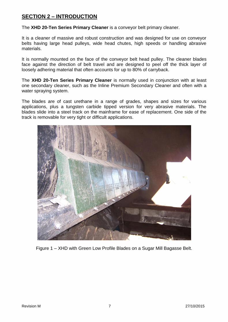
SECTION 2 – INTRODUCTION The XHD 20-Ten Series Primary Cleaner is a conveyor belt primary cleaner. It is a cleaner of massive and robust construction and was designed for use on conveyor belts having large head pulleys, wide head chutes, high speeds or handling abrasive materials. It is normally mounted on the face of the conveyor belt head pulley. The cleaner blades face against the direction of belt travel and are designed to peel off the thick layer of loosely adhering material that often accounts for up to 80% of carryback. The XHD 20-Ten Series Primary Cleaner is normally used in conjunction with at least one secondary cleaner, such as the Inline Premium Secondary Cleaner and often with a water spraying system. The blades are of cast urethane in a range of grades, shapes and sizes for various applications, plus a tungsten carbide tipped version for very abrasive materials. The blades slide into a steel track on the mainframe for ease of replacement. One side of the track is removable for very tight or difficult applications.
Figure 1 – XHD with Green Low Profile Blades on a Sugar Mill Bagasse Belt.
Revision M 8 27/10/2015
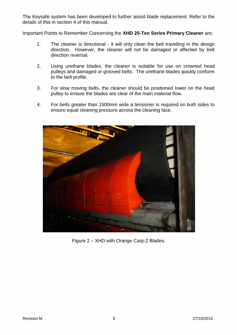
The Keysafe system has been developed to further assist blade replacement. Refer to the details of this in section 4 of this manual. Important Points to Remember Concerning the XHD 20-Ten Series Primary Cleaner are;
1. The cleaner is directional - it will only clean the belt travelling in the design direction. However, the cleaner will not be damaged or affected by belt direction reversal.
2. Using urethane blades, the cleaner is suitable for use on crowned head
pulleys and damaged or grooved belts. The urethane blades quickly conform to the belt profile.
3. For slow moving belts, the cleaner should be positioned lower on the head
pulley to ensure the blades are clear of the main material flow. 4. For belts greater than 1500mm wide a tensioner is required on both sides to
ensure equal cleaning pressure across the cleaning face.
Figure 2 – XHD with Orange Carp-2 Blades.

Revision M 9 27/10/2015
SECTION 3 - PREPARATION FOR INSTALLATION 1. Check Installation Drawings - Ensure that you have the correct drawings
and equipment for your conveyor(s).
2. Pre-assemble the Cleaner(s) and Mounts - Do this in your workshop or
similar free area, rather than at the Conveyor. This will enable you to:
verify all required equipment is present
familiarise yourself with the cleaner assembly
allow you to plan the installation, reducing installation time.
3. Assemble the Necessary Tools & Safety Equipment Required for the Installation.
4. Observe the Conveyor While Running and Conveying Material
Observe the belt splice condition
Does the belt run true, or track off to one side?
Is the Head Pulley out-of-round? Consult ESS if any UNUSUAL conditions are observed in the above. These conditions may result in recommendation of a different installation position or even a different cleaner.

Revision M 10 27/10/2015
SECTION 4 – KEYSAFE FEATURE ESS has incorporated the patented Keysafe blade removal feature in the XHD Primary Cleaner to facilitate safe and easy blade replacement. This feature is now included in all current XHD blades. What is Keysafe? The Keysafe feature is simply a hole through the blade that changes from a round bore to a slot halfway through. This allows an extraction tool with a spade tip to be inserted through the slot into the round bore. The tool is then rotated 90° and withdrawn. The spade tip engages on the shoulder of the slot to pull the blade out of the track. The advantages of this system are many:
Only one blade is withdrawn at a time.
Works from either side of the belt.
No confined space entry required.
No heavy lifts.
Hole is low on centre line of blade for best application of effort.
Optional slide hammer available for tight blades.
Tool is adjustable in length for wide belts or tight spaces.
The Keysafe feature is included in the blades at no cost to clients. The extraction tool is available for purchase from any ESS representative: P/N 36900005 Keysafe Blade Extraction Tool P/N 36900020 Keysafe Tool Slide Hammer
Figure 3 – Typical Cleaner Set-up for Keysafe
Keysafe tool inserted into Keysafe slot
Good access for blade retrieval
Older XHD Mount modified for Keysafe tool insertion

Revision M 11 27/10/2015
4.1 TAKING ADVANTAGE OF THE KEYSAFE FEATURE The Keysafe feature is provided free of charge to purchasers of genuine ESS blades, and has the potential to not only eliminate many of the safety hazards associated with belt cleaner blades changes, but also to dramatically reduce the time taken for a blade change. Task duration reductions of the order of 90% are common, with the cost saving directly to the end user. However, in order to take advantage of this feature, the installer must ensure that the service technician is able to use the Keysafe tool to remove the blades. This is accomplished very easily and at little or no additional cost, and with only a small amount of forethought during installation planning. The main requirements for use of the Keysafe are:
The tool must be able to be inserted into the Keysafe opening, in a relatively
straight line.
When the blade has been withdrawn to the end of the mainframe track, it must be
retrievable by the service technician.
A minimum of about 600 mm clear space is required outside of the chute to enable
the technician to manoeuvre the tool and slide hammer.
To facilitate the above, the ESS XHD 20-Ten Series mounts have been designed in a cutaway shape to allow alignment of the tool with the Keysafe opening. Additionally, cleaner accessories such as the XHD Stand-off Bracket have also been redesigned with the top cut away also to facilitate access for the tool. When combined with an ESS CYA Door, the mount and stand-off bracket will provide excellent access to use the tool and retrieve the blades. Clients are able to custom design similar access, and ESS can provide design assistance on tricky applications. Material fines entering the Keysafe slot can be problematic, but a couple of measures are available to overcome this. For relatively easy to move materials such as coal, simply hosing water into the slot will clear it sufficiently. The Keysafe tool has been recently redesigned to allow use of the slide hammer in the reverse direction. This means that the spade tip can be hammered in to the slot through the fines. ESS is currently working on alternative designs and measures to allow use of the Keysafe feature with even the most difficult materials, so clients are advised to prepare for use of the feature even if it is not usable at this time. The reduction in hazards and task duration will pay for the minimal preparation at the very first service.

Revision M 12 27/10/2015
SECTION 5 USE OF TUNGSTEN CARBIDE TIPPED BLADES ESS has for many years promoted urethane as the preferred material for primary cleaner blades. This is due to the combined qualities of wear resistance, good cleaning performance and, above all, safe application to the belt surface at an attack angle. However, ESS also recognises that there are some applications where urethane is not the best material due usually to a specific property of the material being handled on the conveyor. For example, some extremely sharp and abrasive materials may score the urethane surface and lead to excessive wear. Materials such as Bauxite can catch under the leading edge of urethane blades and cause erratic wear and material by-pass. In these cases, the use of Tungsten Carbide tipped blades can provide a solution. ESS offers Tungsten Carbide tipped blades for the XHD primary cleaner, and these blades are designed to slide directly into the XHD blade track. In 2011, the ESS XHD Tungsten Carbide tipped blade was redesigned for better track fit, inclusion of the Keysafe feature, and to share a replaceable tip with other ESS cleaner models. The new blade has exactly the same installation dimensions as previous versions, but cannot be mixed on the same cleaner. The new blade arrangement uses single blade units where previous versions required a joiner to form 2 or 3 blade assemblies.
Figure 4 – 2011 Model Tungsten Tipped XHD Blade, part number 36500080
Replacement Tip Cast Stainless Steel P/N 36500008sc
Revision M 13 27/10/2015
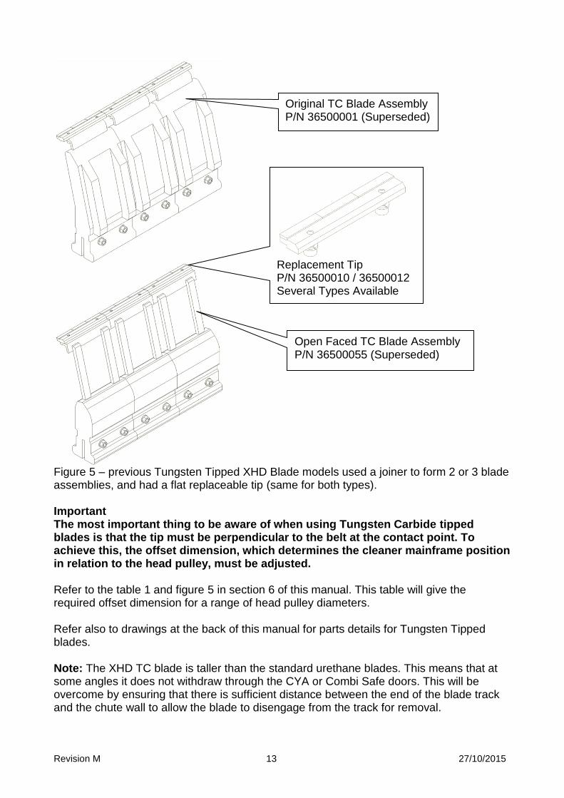
Figure 5 – previous Tungsten Tipped XHD Blade models used a joiner to form 2 or 3 blade assemblies, and had a flat replaceable tip (same for both types). Important The most important thing to be aware of when using Tungsten Carbide tipped blades is that the tip must be perpendicular to the belt at the contact point. To achieve this, the offset dimension, which determines the cleaner mainframe position in relation to the head pulley, must be adjusted. Refer to the table 1 and figure 5 in section 6 of this manual. This table will give the required offset dimension for a range of head pulley diameters. Refer also to drawings at the back of this manual for parts details for Tungsten Tipped blades. Note: The XHD TC blade is taller than the standard urethane blades. This means that at some angles it does not withdraw through the CYA or Combi Safe doors. This will be overcome by ensuring that there is sufficient distance between the end of the blade track and the chute wall to allow the blade to disengage from the track for removal.
Replacement Tip P/N 36500010 / 36500012 Several Types Available
Original TC Blade Assembly P/N 36500001 (Superseded)
Open Faced TC Blade Assembly P/N 36500055 (Superseded)
Revision M 14 27/10/2015
SECTION 6 - INSTALLATION
This section details the procedure for installing the XHD cleaner mainframe and mounts.
Danger Conveyor must be shut down and locked out before any installation or service work is performed.
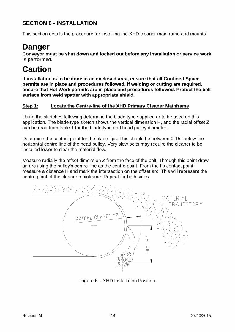
Caution If installation is to be done in an enclosed area, ensure that all Confined Space permits are in place and procedures followed. If welding or cutting are required, ensure that Hot Work permits are in place and procedures followed. Protect the belt surface from weld spatter with appropriate shield. Step 1: Locate the Centre-line of the XHD Primary Cleaner Mainframe Using the sketches following determine the blade type supplied or to be used on this application. The blade type sketch shows the vertical dimension H, and the radial offset Z can be read from table 1 for the blade type and head pulley diameter. Determine the contact point for the blade tips. This should be between 0-15° below the horizontal centre line of the head pulley. Very slow belts may require the cleaner to be installed lower to clear the material flow. Measure radially the offset dimension Z from the face of the belt. Through this point draw an arc using the pulley’s centre-line as the centre point. From the tip contact point measure a distance H and mark the intersection on the offset arc. This will represent the centre point of the cleaner mainframe. Repeat for both sides.
Figure 6 – XHD Installation Position
Revision M 15 27/10/2015
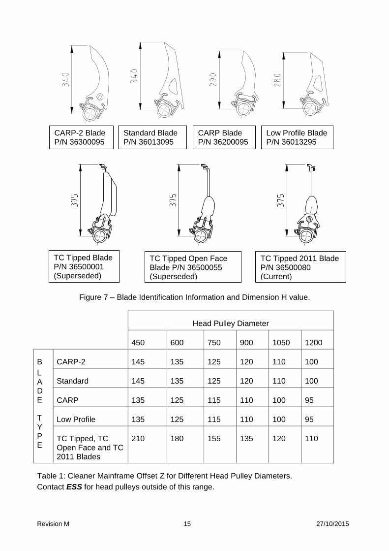
Figure 7 – Blade Identification Information and Dimension H value.
Head Pulley Diameter
450 600 750 900 1050 1200
B
L A D E T Y P E
CARP-2 145 135 125 120 110 100
Standard 145 135 125 120 110 100
CARP 135 125 115 110 100 95
Low Profile 135 125 115 110 100 95
TC Tipped, TC Open Face and TC 2011 Blades
210 180 155 135 120 110
Table 1: Cleaner Mainframe Offset Z for Different Head Pulley Diameters.
Contact ESS for head pulleys outside of this range.
CARP-2 Blade P/N 36300095
Standard Blade P/N 36013095
CARP Blade P/N 36200095
Low Profile Blade P/N 36013295
TC Tipped Blade P/N 36500001 (Superseded)
TC Tipped Open Face Blade P/N 36500055 (Superseded)
TC Tipped 2011 Blade P/N 36500080 (Current)
Revision M 16 27/10/2015
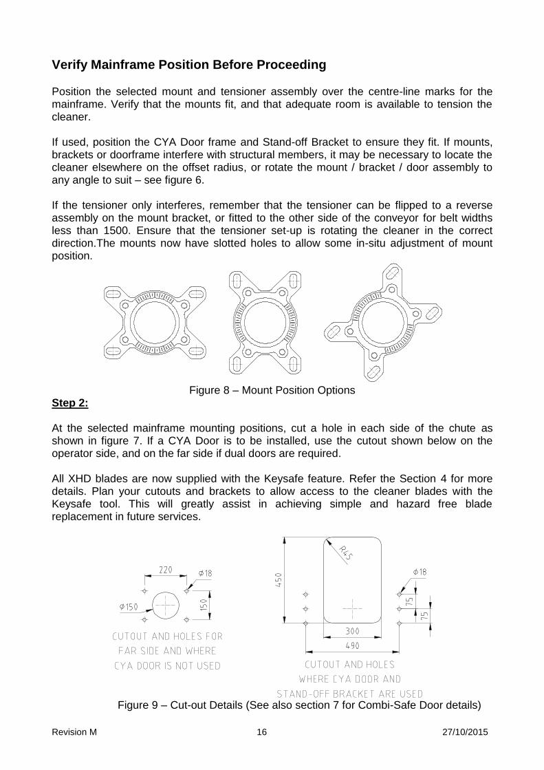
Verify Mainframe Position Before Proceeding
Position the selected mount and tensioner assembly over the centre-line marks for the mainframe. Verify that the mounts fit, and that adequate room is available to tension the cleaner. If used, position the CYA Door frame and Stand-off Bracket to ensure they fit. If mounts, brackets or doorframe interfere with structural members, it may be necessary to locate the cleaner elsewhere on the offset radius, or rotate the mount / bracket / door assembly to any angle to suit – see figure 6. If the tensioner only interferes, remember that the tensioner can be flipped to a reverse assembly on the mount bracket, or fitted to the other side of the conveyor for belt widths less than 1500. Ensure that the tensioner set-up is rotating the cleaner in the correct direction.The mounts now have slotted holes to allow some in-situ adjustment of mount position.
Figure 8 – Mount Position Options
Step 2: At the selected mainframe mounting positions, cut a hole in each side of the chute as shown in figure 7. If a CYA Door is to be installed, use the cutout shown below on the operator side, and on the far side if dual doors are required. All XHD blades are now supplied with the Keysafe feature. Refer the Section 4 for more details. Plan your cutouts and brackets to allow access to the cleaner blades with the Keysafe tool. This will greatly assist in achieving simple and hazard free blade replacement in future services.
Figure 9 – Cut-out Details (See also section 7 for Combi-Safe Door details)
Revision M 17 27/10/2015
Step 3: Remove the blades from the mainframe by first loosening and removing the blade locks. Insert the bare cleaner mainframe through the cutouts in the chute wall. Caution: Remember the XHD is a large and heavy cleaner. Use hoisting equipment or ensure adequate personnel are available to safely lift the cleaner into position. Step 4:
Slide the tensioner side and far side mounts onto the pipe ends of the mainframe and clamp or loosely bolt the mounts to the chute walls with the mainframe in the pre-selected position. If a CYA Door is to be used and the cutout has been made, fit the tensioner side mount to the appropriate stand-off bracket and clamp or bolt the stand-off bracket in the desired position.
Note: Slide CYA doorframe loosely onto the pipe end before the stand-off bracket and mount to save later removal.
Step 5: Check the mainframe position:
Does the centre-line of the mainframe lie the correct offset distance from the belt face? The offset can be checked using ESS XHD Installation Gauges – refer instruction and figure 8 following.
Is the mainframe level or equal to the pulley shaft? Is there at least 165mm clear at one end of the track to remove and replace
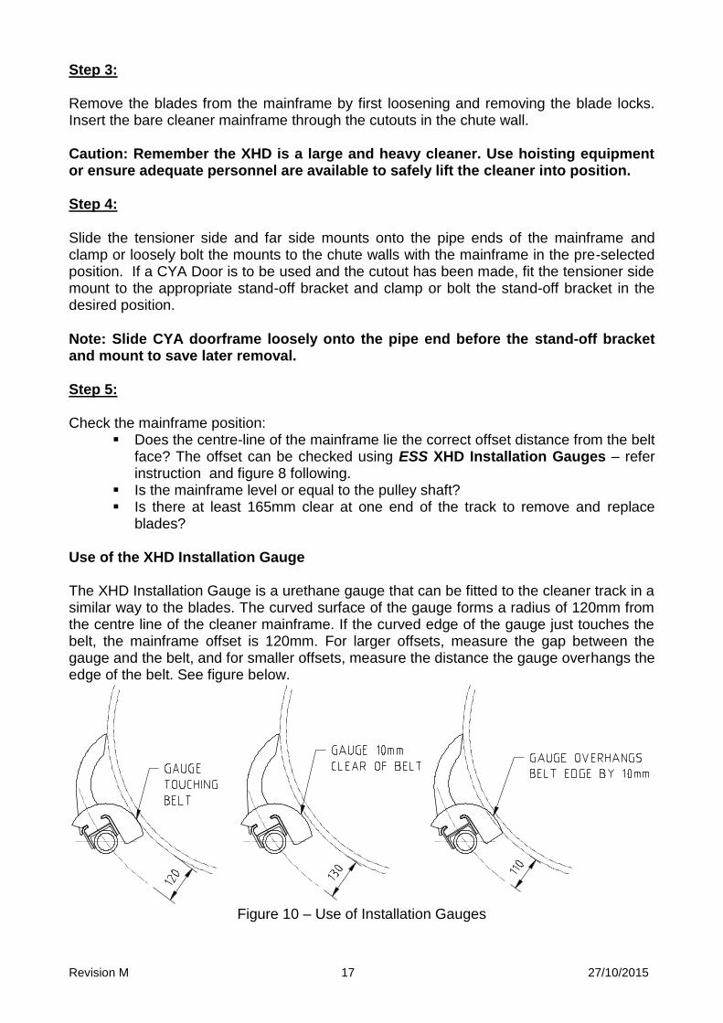
blades? Use of the XHD Installation Gauge The XHD Installation Gauge is a urethane gauge that can be fitted to the cleaner track in a similar way to the blades. The curved surface of the gauge forms a radius of 120mm from the centre line of the cleaner mainframe. If the curved edge of the gauge just touches the belt, the mainframe offset is 120mm. For larger offsets, measure the gap between the gauge and the belt, and for smaller offsets, measure the distance the gauge overhangs the edge of the belt. See figure below.
Figure 10 – Use of Installation Gauges
Revision M 18 27/10/2015
Slide the blades onto the track and fit an Installation Gauge to each end, leaving the blade locks off at this time. Check the offset as described above. Rotate the mainframe until the blade tips lightly contact the belt.
Do the blade tips all touch the belt at the same time? (+1mm). Do the tips contact the belt at the desired position, 0 to 15° below the pulley
centre line, and level across the head pulley? NOTE: Slight inconsistencies in the belt thickness and blade shape, accounting
for small gaps between blade and belt, will quickly be taken up by blade flexure on tensioning.
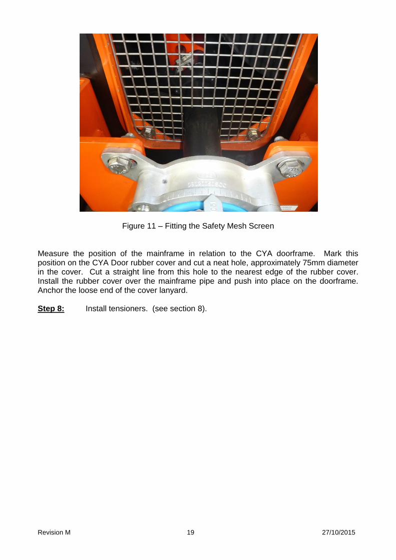
For crowned head pulleys, ensure that the outside blades on each side are an equal distance from the belt whilst the centre blade is touching. Again, these gaps will quickly close on tensioning. If any questions above have been answered “NO”, take appropriate action to correct the installation. If all questions are answered “YES”, proceed. Remove the Installation Gauges, and fit the blade locks, ensuring that the blades are centred to the belt and pulley. Step 6: Fully secure the cleaner mounts, brackets and CYA doorframe to the chute wall. The CYA doorframe is normally stitch welded to the chute wall, but may be drilled and bolted if required. Check all blades and locks are centred on the belt surface or pulley face, and the locks are secured. Step 7: If a CYA Door is used: All ESS CYA Doors for belt cleaning applications are now supplied complete with a mesh safety screen to comply with AS1755 – 2000 Conveyors Safety Requirements. The mesh screen will need to be cut away to fit over the cleaner mainframe. Do this neatly and accurately from the bottom of the screen, to avoid creating sharp edges, and to avoid creating non-compliant openings in the mesh – refer to figure 9. Re-fit the screen to the frame using the fasteners supplied. If a Combi-Safe Door is used, refer to section 7 of this manual.
Revision M 19 27/10/2015
Figure 11 – Fitting the Safety Mesh Screen Measure the position of the mainframe in relation to the CYA doorframe. Mark this position on the CYA Door rubber cover and cut a neat hole, approximately 75mm diameter in the cover. Cut a straight line from this hole to the nearest edge of the rubber cover. Install the rubber cover over the mainframe pipe and push into place on the doorframe. Anchor the loose end of the cover lanyard. Step 8: Install tensioners. (see section 8).
Revision M 20 27/10/2015
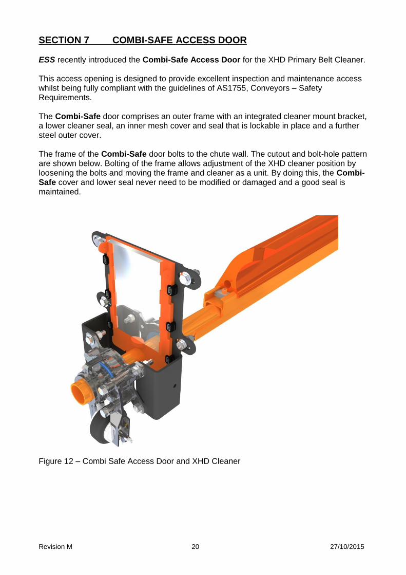
SECTION 7 COMBI-SAFE ACCESS DOOR ESS recently introduced the Combi-Safe Access Door for the XHD Primary Belt Cleaner. This access opening is designed to provide excellent inspection and maintenance access whilst being fully compliant with the guidelines of AS1755, Conveyors – Safety Requirements. The Combi-Safe door comprises an outer frame with an integrated cleaner mount bracket, a lower cleaner seal, an inner mesh cover and seal that is lockable in place and a further steel outer cover. The frame of the Combi-Safe door bolts to the chute wall. The cutout and bolt-hole pattern are shown below. Bolting of the frame allows adjustment of the XHD cleaner position by loosening the bolts and moving the frame and cleaner as a unit. By doing this, the Combi-Safe cover and lower seal never need to be modified or damaged and a good seal is maintained.
Figure 12 – Combi Safe Access Door and XHD Cleaner
Revision M 21 27/10/2015
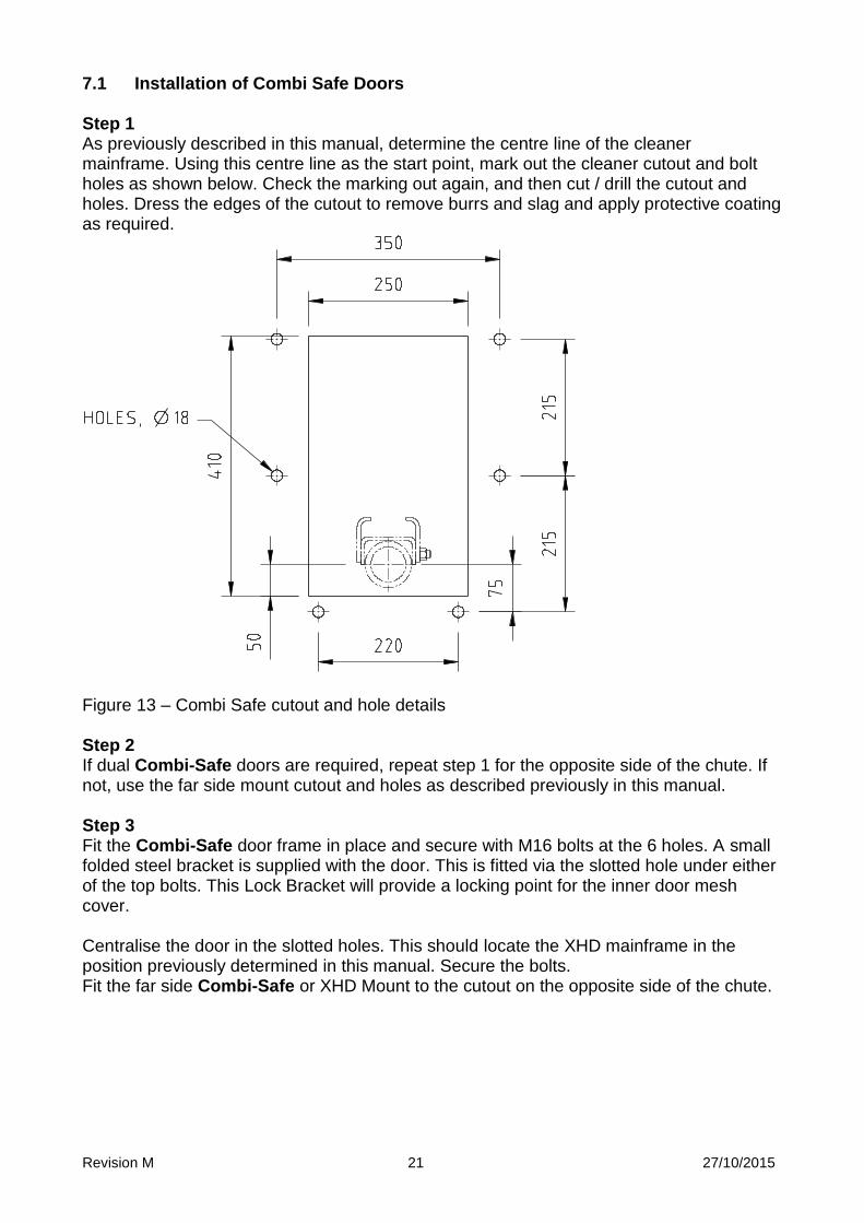
7.1 Installation of Combi Safe Doors Step 1 As previously described in this manual, determine the centre line of the cleaner mainframe. Using this centre line as the start point, mark out the cleaner cutout and bolt holes as shown below. Check the marking out again, and then cut / drill the cutout and holes. Dress the edges of the cutout to remove burrs and slag and apply protective coating as required.
Figure 13 – Combi Safe cutout and hole details Step 2 If dual Combi-Safe doors are required, repeat step 1 for the opposite side of the chute. If not, use the far side mount cutout and holes as described previously in this manual. Step 3 Fit the Combi-Safe door frame in place and secure with M16 bolts at the 6 holes. A small folded steel bracket is supplied with the door. This is fitted via the slotted hole under either of the top bolts. This Lock Bracket will provide a locking point for the inner door mesh cover. Centralise the door in the slotted holes. This should locate the XHD mainframe in the position previously determined in this manual. Secure the bolts. Fit the far side Combi-Safe or XHD Mount to the cutout on the opposite side of the chute.
Revision M 22 27/10/2015
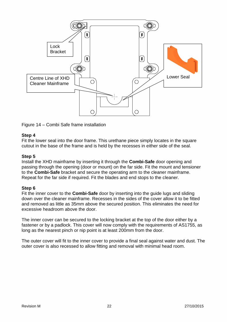
Figure 14 – Combi Safe frame installation Step 4 Fit the lower seal into the door frame. This urethane piece simply locates in the square cutout in the base of the frame and is held by the recesses in either side of the seal. Step 5 Install the XHD mainframe by inserting it through the Combi-Safe door opening and passing through the opening (door or mount) on the far side. Fit the mount and tensioner to the Combi-Safe bracket and secure the operating arm to the cleaner mainframe. Repeat for the far side if required. Fit the blades and end stops to the cleaner. Step 6 Fit the inner cover to the Combi-Safe door by inserting into the guide lugs and sliding down over the cleaner mainframe. Recesses in the sides of the cover allow it to be fitted and removed as little as 35mm above the secured position. This eliminates the need for excessive headroom above the door. The inner cover can be secured to the locking bracket at the top of the door either by a fastener or by a padlock. This cover will now comply with the requirements of AS1755, as long as the nearest pinch or nip point is at least 200mm from the door. The outer cover will fit to the inner cover to provide a final seal against water and dust. The outer cover is also recessed to allow fitting and removal with minimal head room.
Lower Seal
Lock Bracket
Centre Line of XHD Cleaner Mainframe
Revision M 23 27/10/2015
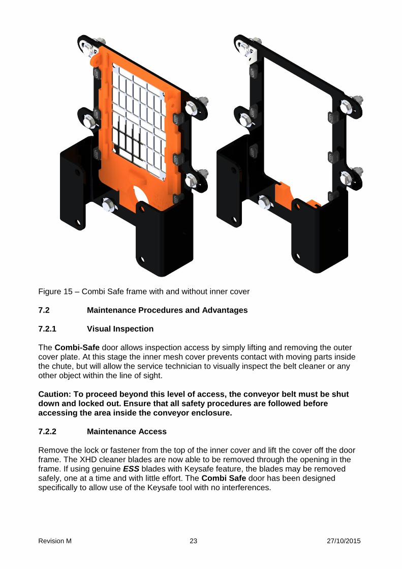
Figure 15 – Combi Safe frame with and without inner cover 7.2 Maintenance Procedures and Advantages 7.2.1 Visual Inspection The Combi-Safe door allows inspection access by simply lifting and removing the outer cover plate. At this stage the inner mesh cover prevents contact with moving parts inside the chute, but will allow the service technician to visually inspect the belt cleaner or any other object within the line of sight. Caution: To proceed beyond this level of access, the conveyor belt must be shut down and locked out. Ensure that all safety procedures are followed before accessing the area inside the conveyor enclosure. 7.2.2 Maintenance Access Remove the lock or fastener from the top of the inner cover and lift the cover off the door frame. The XHD cleaner blades are now able to be removed through the opening in the frame. If using genuine ESS blades with Keysafe feature, the blades may be removed safely, one at a time and with little effort. The Combi Safe door has been designed specifically to allow use of the Keysafe tool with no interferences.

Revision M 24 27/10/2015
If the XHD cleaner has been fitted with an ESS XHD Mandrel, the complete cleaner may be withdrawn through the Combi Safe door. Remove the tensioner and mount assembly from the Combi Safe door by first removing the four bolts. Loosen the lockscrews securing the tensioner to the mainframe and slide the mount and tensioner assembly from the mainframe. Caution: When the lockscrews are loosened, the cleaner mainframe may spin. Keep fingers clear of any pinch points. Caution: When withdrawing the tensioner, take care that the individual parts of the tensioner are supported. The parts may relax / fall when coming clear and could cause impact injury. Lift the end of the cleaner mainframe and remove the lower seal. This will allow the mainframe to rest on the Combi Safe frame at any time during withdrawal. Do not forget to re-fit the lower seal when re-installing the cleaner. Refer to the XHD Mandrel manual for more information. On completion of maintenance, re-fit the inner mesh cover and secure with the designated locking system. Set the tensioner(s) to the required setting and check the blade contact with the belt. Fit the outer cover, and remove locks or tags so that the conveyor can be returned to service.
Revision M 25 27/10/2015
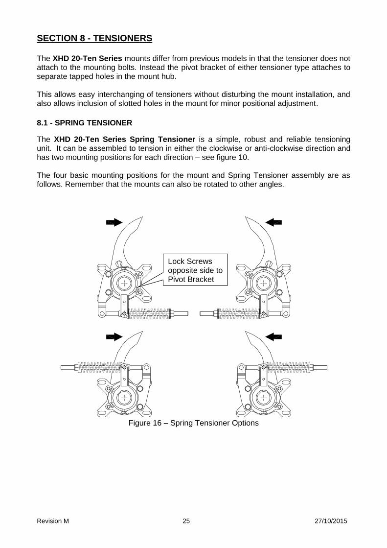
SECTION 8 - TENSIONERS
The XHD 20-Ten Series mounts differ from previous models in that the tensioner does not attach to the mounting bolts. Instead the pivot bracket of either tensioner type attaches to separate tapped holes in the mount hub.
This allows easy interchanging of tensioners without disturbing the mount installation, and
also allows inclusion of slotted holes in the mount for minor positional adjustment. 8.1 - SPRING TENSIONER
The XHD 20-Ten Series Spring Tensioner is a simple, robust and reliable tensioning unit. It can be assembled to tension in either the clockwise or anti-clockwise direction and has two mounting positions for each direction – see figure 10. The four basic mounting positions for the mount and Spring Tensioner assembly are as follows. Remember that the mounts can also be rotated to other angles.
Figure 16 – Spring Tensioner Options
Lock Screws opposite side to Pivot Bracket
Revision M 26 27/10/2015
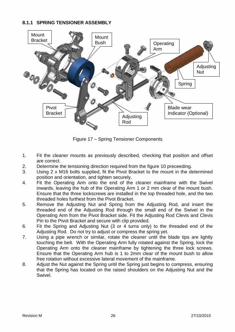
8.1.1 SPRING TENSIONER ASSEMBLY
Figure 17 – Spring Tensioner Components
1. Fit the cleaner mounts as previously described, checking that position and offset
are correct. 2. Determine the tensioning direction required from the figure 10 preceeding. 3. Using 2 x M16 bolts supplied, fit the Pivot Bracket to the mount in the determined
position and orientation, and tighten securely. 4. Fit the Operating Arm onto the end of the cleaner mainframe with the Swivel
inwards, leaving the hub of the Operating Arm 1 or 2 mm clear of the mount bush. Ensure that the three lockscrews are installed in the top threaded hole, and the two threaded holes furthest from the Pivot Bracket.
5. Remove the Adjusting Nut and Spring from the Adjusting Rod, and insert the threaded end of the Adjusting Rod through the small end of the Swivel in the Operating Arm from the Pivot Bracket side. Fit the Adjusting Rod Clevis and Clevis Pin to the Pivot Bracket and secure with clip provided.
6. Fit the Spring and Adjusting Nut (3 or 4 turns only) to the threaded end of the Adjusting Rod. Do not try to adjust or compress the spring yet.
7. Using a pipe wrench or similar, rotate the cleaner until the blade tips are lightly touching the belt. With the Operating Arm fully rotated against the Spring, lock the Operating Arm onto the cleaner mainframe by tightening the three lock screws. Ensure that the Operating Arm hub is 1 to 2mm clear of the mount bush to allow free rotation without excessive lateral movement of the mainframe.
8. Adjust the Nut against the Spring until the Spring just begins to compress, ensuring that the Spring has located on the raised shoulders on the Adjusting Nut and the Swivel.
Mount Bracket
Operating Arm
Spring
Adjusting Nut
Pivot Bracket
Mount Bush
Blade wear Indicator (Optional)
Adjusting Rod
Revision M 27 27/10/2015
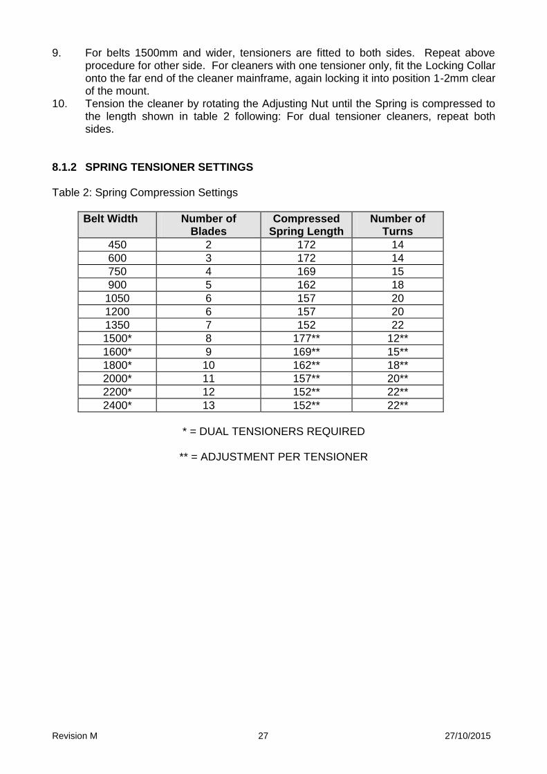
9. For belts 1500mm and wider, tensioners are fitted to both sides. Repeat above procedure for other side. For cleaners with one tensioner only, fit the Locking Collar onto the far end of the cleaner mainframe, again locking it into position 1-2mm clear of the mount.
10. Tension the cleaner by rotating the Adjusting Nut until the Spring is compressed to the length shown in table 2 following: For dual tensioner cleaners, repeat both sides.
8.1.2 SPRING TENSIONER SETTINGS Table 2: Spring Compression Settings
Belt Width Number of Blades
Compressed Spring Length
Number of Turns
450 2 172 14
600 3 172 14
750 4 169 15
900 5 162 18
1050 6 157 20
1200 6 157 20
1350 7 152 22
1500* 8 177** 12**
1600* 9 169** 15**
1800* 10 162** 18**
2000* 11 157** 20**
2200* 12 152** 22**
2400* 13 152** 22**
* = DUAL TENSIONERS REQUIRED
** = ADJUSTMENT PER TENSIONER
Revision M 28 27/10/2015
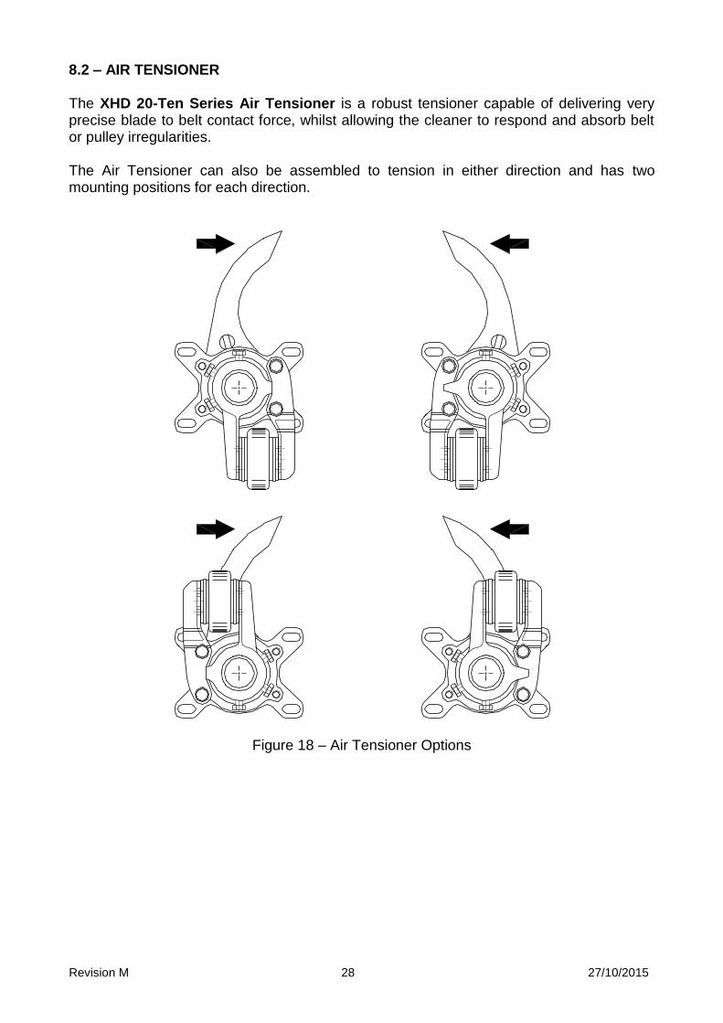
8.2 – AIR TENSIONER The XHD 20-Ten Series Air Tensioner is a robust tensioner capable of delivering very precise blade to belt contact force, whilst allowing the cleaner to respond and absorb belt or pulley irregularities. The Air Tensioner can also be assembled to tension in either direction and has two mounting positions for each direction.
Figure 18 – Air Tensioner Options
Revision M 29 27/10/2015
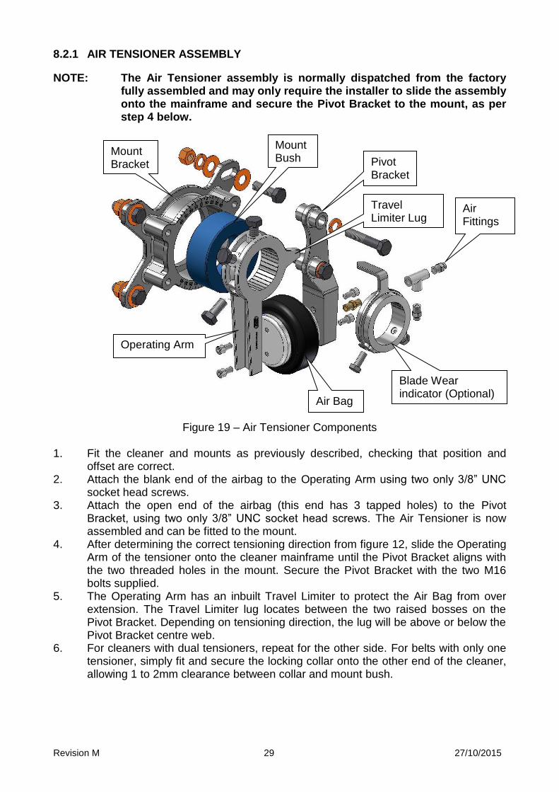
8.2.1 AIR TENSIONER ASSEMBLY
NOTE: The Air Tensioner assembly is normally dispatched from the factory fully assembled and may only require the installer to slide the assembly onto the mainframe and secure the Pivot Bracket to the mount, as per step 4 below.
Figure 19 – Air Tensioner Components 1. Fit the cleaner and mounts as previously described, checking that position and
offset are correct. 2. Attach the blank end of the airbag to the Operating Arm using two only 3/8” UNC
socket head screws. 3. Attach the open end of the airbag (this end has 3 tapped holes) to the Pivot
Bracket, using two only 3/8” UNC socket head screws. The Air Tensioner is now assembled and can be fitted to the mount.
4. After determining the correct tensioning direction from figure 12, slide the Operating Arm of the tensioner onto the cleaner mainframe until the Pivot Bracket aligns with the two threaded holes in the mount. Secure the Pivot Bracket with the two M16 bolts supplied.
5. The Operating Arm has an inbuilt Travel Limiter to protect the Air Bag from over extension. The Travel Limiter lug locates between the two raised bosses on the Pivot Bracket. Depending on tensioning direction, the lug will be above or below the Pivot Bracket centre web.
6. For cleaners with dual tensioners, repeat for the other side. For belts with only one tensioner, simply fit and secure the locking collar onto the other end of the cleaner, allowing 1 to 2mm clearance between collar and mount bush.
Pivot Bracket
Mount Bracket
Air Fittings
Operating Arm
Mount Bush
Air Bag
Blade Wear indicator (Optional)
Travel Limiter Lug
Revision M 30 27/10/2015
7. Do not install or connect air supply fittings at this stage. Using a pipe wrench or similar, grip and rotate the cleaner mainframe until the blade tips lightly touch the belt surface at the cleaning position. With the airbag fully compressed, secure the operating arm to the cleaner mainframe using the three locking screws. Ensure a clearance of 1 to 2mm between the operating arm and the mount bush to enable free rotation whilst minimising lateral movement. For dual tensioners, repeat for the other side.
8. The cleaner is now ready for the attachment of the air supply system. 8.2.2 AIR SUPPLY CONNECTION
The XHD 20-Ten Series Air Tensioner Assembly is supplied with a ¼” BSP / 6mm push fit tube connector. This fitting is simply screwed into the air bag, and the 6mm air supply tube pushed into the fitting.
For cleaners with dual tensioners, additional fittings are supplied to allow the air supply to be connected to both air bags via a tee. The 6mm tube is passed through the cleaner mainframe to provide air to the far side airbag.
Connect all air fittings using a good quality liquid compound or gas seal thread tape.
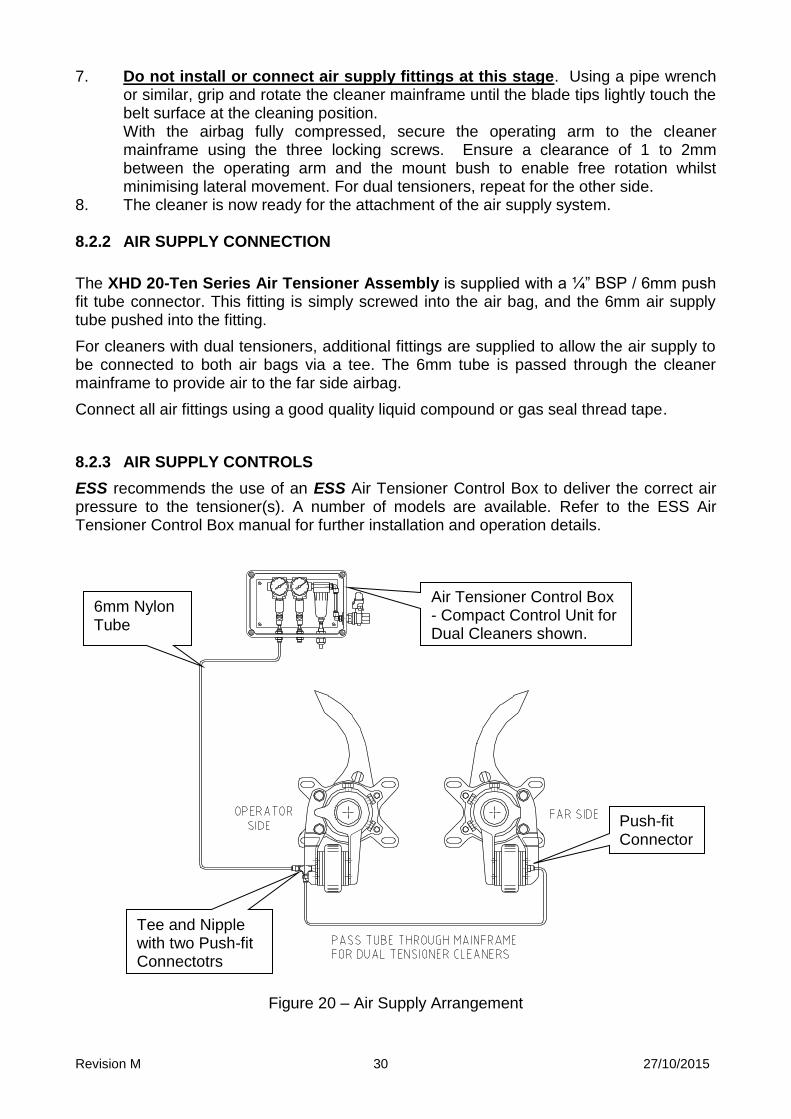
8.2.3 AIR SUPPLY CONTROLS
ESS recommends the use of an ESS Air Tensioner Control Box to deliver the correct air pressure to the tensioner(s). A number of models are available. Refer to the ESS Air Tensioner Control Box manual for further installation and operation details.
Figure 20 – Air Supply Arrangement
6mm Nylon Tube
Tee and Nipple with two Push-fit Connectotrs
Push-fit Connector
Air Tensioner Control Box - Compact Control Unit for Dual Cleaners shown. See options below.

Revision M 31 27/10/2015
Control boxes available include:
Part Number Description Enclosure Material
09000123M Air Ten Compact Control Box – 1 Cleaner Plastic
09000124M Air Ten Compact Control Box – 2 Cleaners Plastic
09000125M Air Ten Compact Control Box – 3Cleaners Plastic
09000126M Air Ten Compact Control Box – 4 Cleaners Plastic
09000115M Air Ten Control Box – 1 Cleaner Stainless Steel
09000116M Air Ten Control Box – 2 Cleaners Stainless Steel
09000117M Air Ten Control Box – 3 Cleaners Stainless Steel
09000118M Air Ten Control Box – 4 Cleaners Stainless Steel
The Air Tensioner Control Boxes are available with optional solenoid valve. Once the fittings are connected and secured, the air tensioner may be pressurised. Pressures are indicated in table 3. On completion, pressure check all fittings and connections using soapy water or equivalent to ensure no leaks are present. Rectify any leaks found – compressed air losses can account for substantial plant running costs. Table 3: Air Pressure Settings
PRESSURES
BELT WIDTH kPa
PSI
450 55 8
600 69 10
750 82 12
900 96 14
1050 110 16
1200 124 18
1350 138 20
1500 *82 *12
1600 *96 *14
1800 *96 *14
2000 *110 *16
2200 *124 *18
2400 *138 *20
* = Two Tensioners fitted.

Revision M 32 27/10/2015
8.3 OPTIONAL WEAR INDICATOR
The XHD 20-Ten Series mount set includes an optional blade wear indicator. Correctly set up, the wear indicator will provide the operator with an instant visual estimate of the wear status of the cleaning blades. It is important to note that the wear indicator should not replace or reduce the need for regular inspection of the cleaning blades.
The Wear Indicator is simply a pointer that rotates with the cleaner mainframe as the blades wear, with the amount of rotation indicated on a scale cast into the mount bracket. The scale is set out in 5° increments from 0° to 40°.
Different ESS XHD blades have varying amounts of rotational wearlife, and these can vary further with operating conditions. For example, the Standard, CARP and Low Profile blades will have approximately 25° of wearlife, whilst the CARP-2 blade can achieve up to 40° in many applications. The Wear Indicator is not used with Tungsten Carbide tipped blades, which have minimal rotation.
It is therefore essential that the operator know what type of blade is being used, and have some experience of the wearlife achieved on the belt in question. Allowing the blades to wear too far can result in blade pull-through (with mainframe damage common). Changing the blades too early will increase blade replacement costs.
8.3.1 SETTING THE WEAR INDICATOR
Setting the indicator is very simple. With a new set of blades installed and tensioned against the belt, install the indicator over the end of the cleaner mainframe with the pointer aimed at the 0 mark on the mount. Tighten the lockscrews.
As the blades wear, the indicator will rotate and show the amount of rotation on the scale. It is recommended that the operator determine the amount of rotation expected from the blades being used, and mark with paint or permanent marker the expected maximum wear life point on the scale.
It is essential that regular blade inspections are carried out, especially as the wear life approaches the expected limit.
Where the Wear Indicator is used with an Air Tensioner, and the Air Tensioner is reset during the blade wear life (see section 9.3), do not reset the Wear Indicator. It must remain at the original position in order the indicate total travel from the start point.
Figure 21 – Fitting the Wear Indicator

Revision M 33 27/10/2015
SECTION 9 - CENTRE PIVOT MAINFRAME In some applications, the migration of very abrasive fines to the centre of the belt will result in excessive wear rates on the centre blades of the XHD cleaner. This will in turn result in the centre blades losing contact with the belt surface. The outer unworn blades effectively hold the worn centre blades away from the belt. To overcome this, ESS developed the Centre Pivot Mainframe. This mainframe has a separate portion of the blade track, usually 3 blades wide, that can be rotated against the belt independently of the rest of the blade set. This separate track section has its own air bag tensioner mounted in a protected position under the mainframe. The Centre Pivot Mainframe is available for air tensioned cleaners only. In the rest position, or without any air applied, the centre blades will align with all other blades in the blade set. When air pressure is applied to the centre tensioner, the centre blades will pivot forward against the belt to take up excessive wear. On release of air pressure a spring retractor will return the blades to the base position. The set-up of the Centre Pivot Mainframe is exactly the same as described previously for the standard air tensioned XHD cleaner. Room must be available to insert the mainframe with centre tensioner into the chute, but otherwise cleaner installation is unchanged. To further compensate for centre wear, ESS offers an enlarged one-piece blade called the Mega-Blade. This blade is available in Standard and Carp-2 blade shapes. The Mega-blade has increased volume in the blade tip to reduce wear rates, plus reinforcing ribs to resist deflection under load. The Mega-blade is equivalent to 3 blades wide (about 490mm), and is designed to fit as a single unit into the Centre Pivot mainframe. The installation position of the mainframe when using Mega-blades is the same as that for the original blade type. The Mega-blade is usually combined with an equal number of standard sized blades either side to make up a complete blade set for the required belt width. Refer to the drawing at the back of this manual. 9.1 AIR CONNECTIONS AND SETTINGS FOR CENTRE PIVOT MAINFRAMES The Centre Pivot Mainframe has an additional air line connection over standard air tensioned cleaners. The extra air line is to supply air to the centre pivot airbag. The air line extends from the centre pivot air bag into the mainframe and out through the operator end of the mainframe. This air line is connected to a separate outlet from the control box and has a separate regulator to allow the pressure to the centre pivot to be independently adjusted.
Revision M 34 27/10/2015
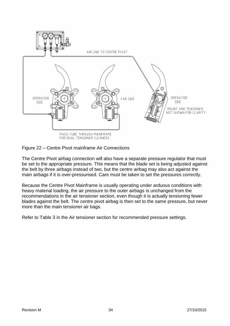
Figure 22 – Centre Pivot mainframe Air Connections The Centre Pivot airbag connection will also have a separate pressure regulator that must be set to the appropriate pressure. This means that the blade set is being adjusted against the belt by three airbags instead of two, but the centre airbag may also act against the main airbags if it is over-pressurised. Care must be taken to set the pressures correctly. Because the Centre Pivot Mainframe is usually operating under arduous conditions with heavy material loading, the air pressure to the outer airbags is unchanged from the recommendations in the air tensioner section, even though it is actually tensioning fewer blades against the belt. The centre pivot airbag is then set to the same pressure, but never more than the main tensioner air bags. Refer to Table 3 in the Air tensioner section for recommended pressure settings.

Revision M 35 27/10/2015
SECTION 10 - COMMISSIONING
Step 1: Perform Installation Check.
Double check the items in previous sections – safety, preparation, installation. Check that the cleaner is installed to specification, all fasteners have been securely tightened, and the tensioners adjusted to the correct settings.
Step 2: Is the belt empty?
Make sure there are no foreign objects such as tools or clean-up debris left on the belt. They may damage the belt cleaners or the conveyor systems.
Step 3: Load material on the conveyor.
If possible, test run conveyor with material on the belt. This helps to quickly “wear in” the blades and reduce the initial friction between the belt and the blades. The belt may also be moistened with water.
Step 4: Start the conveyor. Ensure first that all screens and safety barriers are in place. Allow only visual access to the cleaner blades, ensuring that no person can enter or reach into the conveyor enclosure. Follow all safety procedures before starting the conveyor. Step 5: Observe the cleaning action.
Observe the action of the cleaner. Look for blades that are not touching the belt. All blade tips should be in contact with the belt and peeling material from the belt. Run for several belt rotations to appraise the action and effect of the splices on the belt cleaner.
Step 5: Check the Tensioner Setting.
Refer to previous section 6 – Operation of Tensioner. After running, check and reset (if necessary) the cleaner tensioner setting. Initial running and bedding-in can loosen parts and reduce the tensioner loading. Do not over-tension - excessive pressure unnecessarily reduces the life of the blade, without any increase in the cleaner effectiveness.
Step 7: Train Operators and Maintenance Personnel.
Ensure that operators and service personnel are aware and familiar with the cleaning system. Ensure that they are aware of all safety hazards that exist around conveyor belts, and that all safety procedures are followed. Thoroughly train service personnel in inspection and maintenance of the cleaning system. Contact ESS for assistance if required.
Step 8: Return the system to production. Follow all plant procedures to return the conveyor system to operational status.

Revision M 36 27/10/2015
SECTION 11 – OPERATOR TRAINING The decision to purchase the XHD 20-Ten Series Primary Belt Cleaner is a major step toward the realisation of a clean plant. The next step is to train personnel to maintain and service the equipment (or employ ESS to maintain the belt cleaning equipment) so that it continues to operate at optimum efficiency. The benefits of efficient cleaners outweigh the cost of maintaining the cleaners many times over.If you wish to have your cleaning system maintained for you contact ESS. If not, train your own personnel as follows;
1. Ensure that personnel working around conveyors are thoroughly trained to recognise existing and potential hazards involved, and that a Job Safety Analysis is conducted to identify and control those hazards.
2. Ensure personnel are trained in correct equipment isolation and lock-out procedures.
3. Ensure that personnel have all required safety equipment and are thoroughly trained in the use of that equipment.
4. Ensure that all appropriate permits are in place, and that personnel involved are qualified to undertake the required work.
5. Provide the trainee with a copy of this manual and ensure that they read and understand the contents.
6. Provide the trainee with all relevant conveyor data, such as belt speed, width and material handled, and ensure that they understand the required belt cleaner settings and adjustments that pertain to the conveyor.
7. Instruct the trainee to look for problems existing or developing in the belt cleaning system, such as increasing carryback, irregular or excessive blade wear, blade vibration and the like. Encourage them to safely observe and try to determine the cause of the problem.
8. Ensure that the trainee is given hands-on instruction in maintenance procedures during down-time, in the company of an experienced service technician.
9. Ensure that the trainee is provided additional support and instruction at regular future intervals to ensure that all information has been understood and retained.
10. Encourage the trainee to look for and report other problems developing on the conveyor system such as excessive belt tracking, belt damage, seized idlers, missing bolts and the like.
Revision M 37 27/10/2015
SECTION 12 – ROUTINE MAINTENANCE AND SERVICE
Regular inspection and servicing is the key to effective conveyor belt cleaning. It is recommended that the cleaner be visually inspected once per week. Actual service intervals will vary considerably from plant to plant.
CAUTION
Do not reach inside the conveyor chute under any circumstances whilst the conveyor is running.
12.1 ROUTINE INSPECTION PROCEDURE Step 1: Inspect the condition of the cleaner. Open the inspection door (if safety
compliant), and observe the condition and action of the blades and cleaner. If the blades are excessively worn or damaged, schedule a blade changeout at the next available opportunity. Refer to the blade change procedure following.
Step 2: If necessary (and if plant rules allow it), hose any material build-up from the
blades or mainframe – do this through the safety mesh screen.
DO NOT REACH INTO THE CHUTE WHILST CONVEYOR IS RUNNING. Step 3: Check the tensioner settings and adjust if necessary. DO NOT OVER
TENSION – refer to the tensioner settings in Section 6 for the required belt width.
Step 4: For Air Tensioned cleaners only - Carefully inspect the air tensioner to
determine the position of the safety stop lug. If the lug is close to the raised hub of the pivot bracket, but the blades still have substantial wear life, the air tensioner will need to be reset. This job will require the conveyor to be shut down, and should be programmed for the next available opportunity. Refer to the procedure following in 9.3.
12.2 BLADE SERVICE PROCEDURE Step 1: Shut down and lock out the conveyor. Never try to replace the Blades on
an XHD Primary Cleaner with the conveyor running. Severe injury or death can result from contact with a moving conveyor belt.
Step 2: Release the tension and back blades away from the belt. For the Spring
Tensioner, release the adjusting nut. For the Air Tensioner, close the isolation valve for the cleaner in the air control box.
Step 3: Remove the safety screen to access the cleaner, then release and remove
the operator side blade lock.
Revision M 38 27/10/2015
Step 4: Slide the blade assemblies off the cleaner mainframe, utilising the Keysafe feature where possible – see section 4
. Step 5: Clean and inspect the blades – if worn excessively or otherwise damaged,
replace with new blades. Always replace blades as a full set. Step 6: Re-install (new) blades onto cleaner, followed by lock. Step 7: Re-tension cleaner onto the belt as previously described in the Tensioners
section 6. Step 8: Remove all tools or debris from belt. Replace all access screens and guards. Step 8: Remove locks or tags and restart belt. Observe cleaner action and blade
effectiveness. Replace CYA Door rubber cover if installed. Clean up work area.
12.3 RE-SETTING THE AIR TENSIONER
This procedure is used when the Air Tensioner travel limiting lug is in contact or close to contacting the Pivot Bracket hub, but substantial wear life remains in the blades.
Step 1 Shut down and lock out the conveyor. There is no need to enter the chute
to perform this task, but the technician will be required to release the lockscrews to the mainframe and may be exposed to a twisting hazard if the blades are impacted by a moving belt or material load.
Step 2 Release the air pressure by closing the isolating valve in the control box. Step 3 Release the lockscrews securing the Operating Arm to the mainframe, but do
not release the blade wear indicator (if fitted). Caution: For single tensioner cleaners, the mainframe may rotate sharply –
keep fingers clear. On dual tensioner cleaners, the opposite side tensioner will hold the mainframe in place.
Step 4 An assistant may be required for this step. Using a pipe wrench or similar,
rotate the mainframe until the blades touch the belt, and hold in that position. Fully compress the air bag, and secure the lockscrews in the Operating Arm onto the mainframe while the air bag is compressed. Release the mainframe.
Step 5 For dual tensioner cleaners, repeat for the other side. Step 6 Turn on the air supply and adjust the pressure as described in section 6. Step 7 Remove locks or tags and return the belt to service. Observe the cleaner in
operation, then replace the access door cover.
Revision M 39 27/10/2015
SECTION 13 – TROUBLE SHOOTING .
Problem: Mounts won’t fit in desired location
CAUSE
SOLUTION
Structural members in the way. Relocate the cleaner elsewhere on the offset radial. Consult ESS if unsure. Modify structural members only as a last resort, and only with plant engineer approval.
Obstructions prevent mounting to chute wall.
Provide gussets or spacers to secure mounts away from obstructions.
Problem: Blades fold under at Start-up
CAUSE
SOLUTION
Incorrect mainframe offset Relocate mounts so that the shaft is the correct radial distance from the belt face on the head pulley – see section 5.
Excessive tension Relax blade tension to recommended settings in section 6.
Belt running dry Always put material on belt for start-up or a little water if material is unavailable.
Poor belt or splice condition Repair belt, dress splices to smooth contour.
New belt with sticky surface Fit low friction blades – contact ESS for assistance.
Problem: Poor blade life
CAUSE
SOLUTION
Excessive tension Relax blade tension to recommended settings in section 6.
Improper blade application Consult ESS.
Revision M 40 27/10/2015
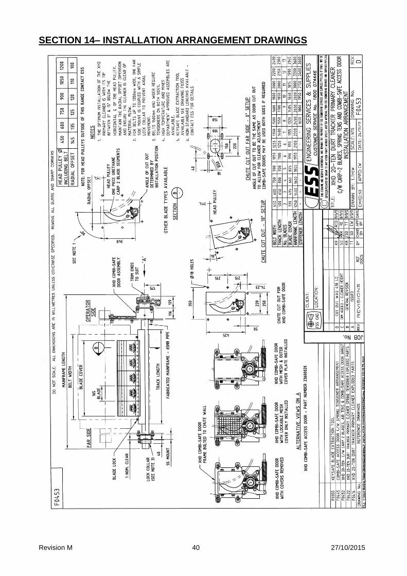
SECTION 14– INSTALLATION ARRANGEMENT DRAWINGS
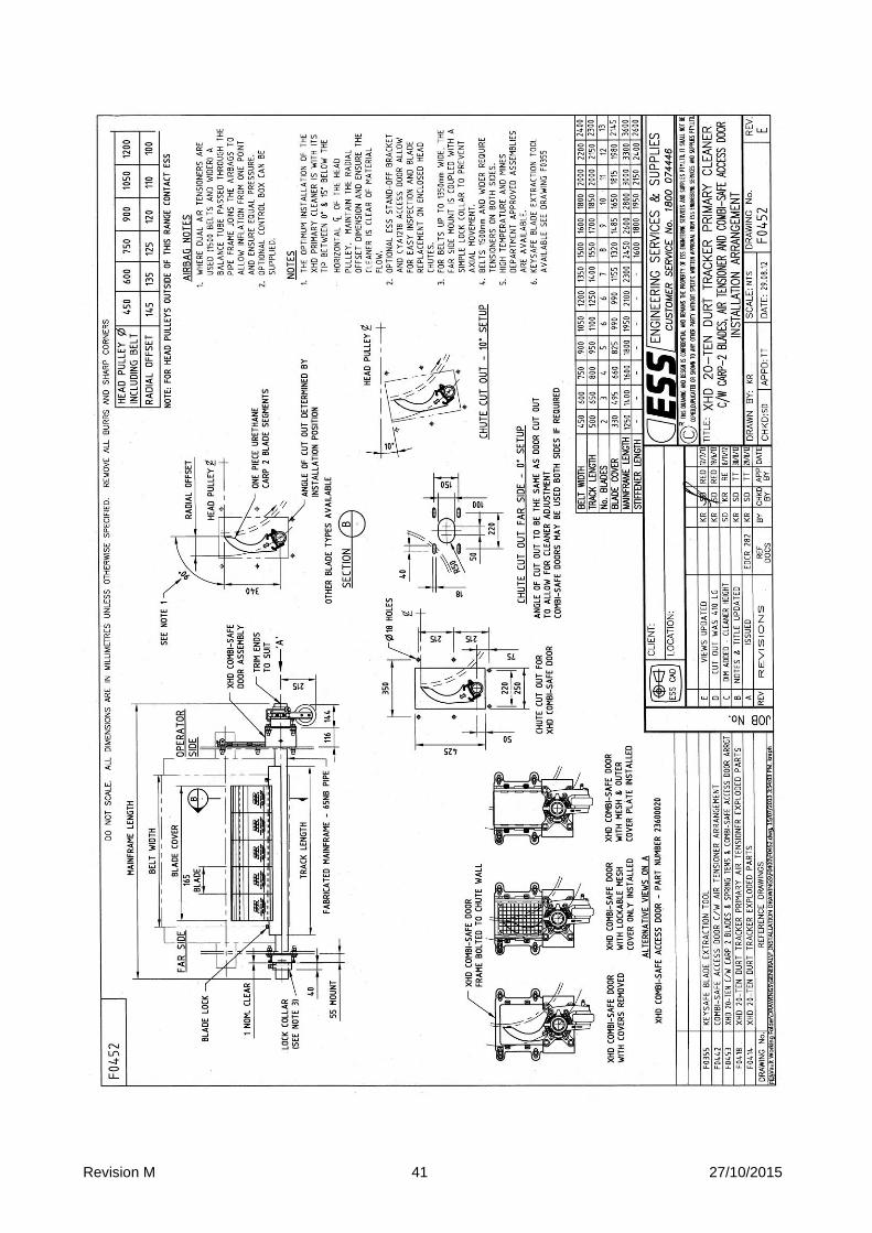
Revision M 41 27/10/2015
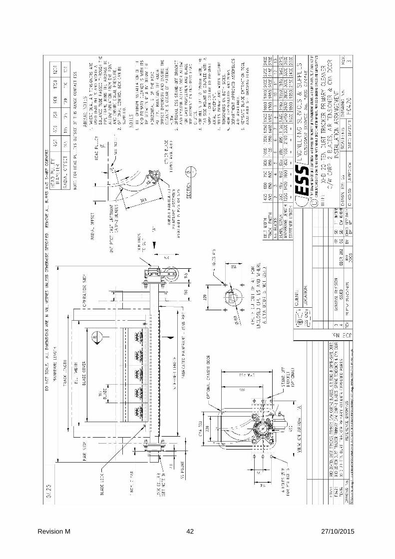
Revision M 42 27/10/2015
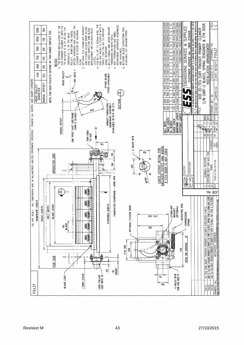
Revision M 43 27/10/2015
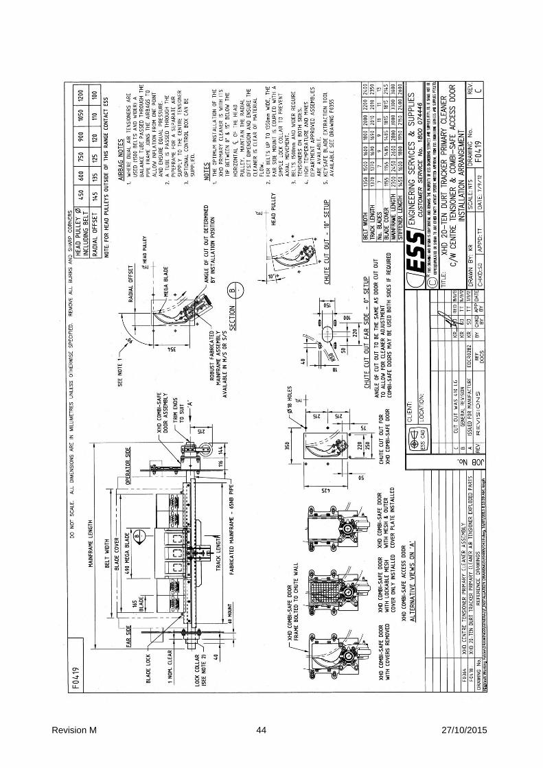
Revision M 44 27/10/2015
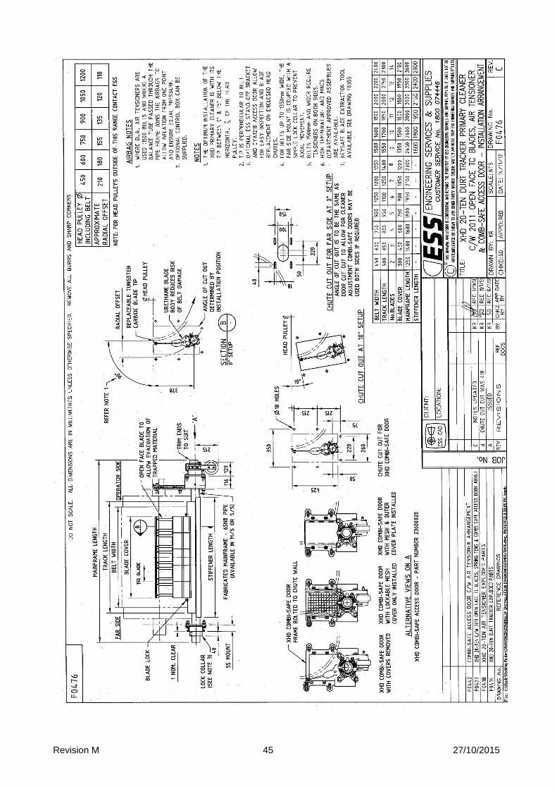
Revision M 45 27/10/2015
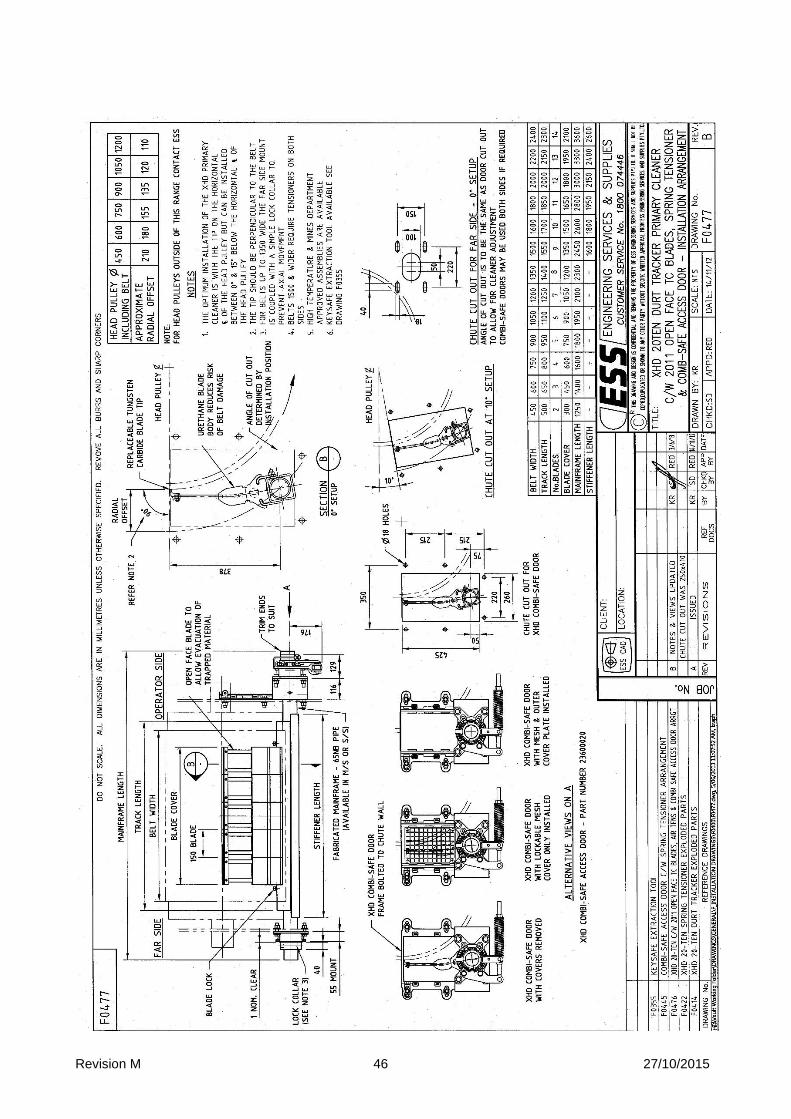
Revision M 46 27/10/2015
Revision M 47 27/10/2015
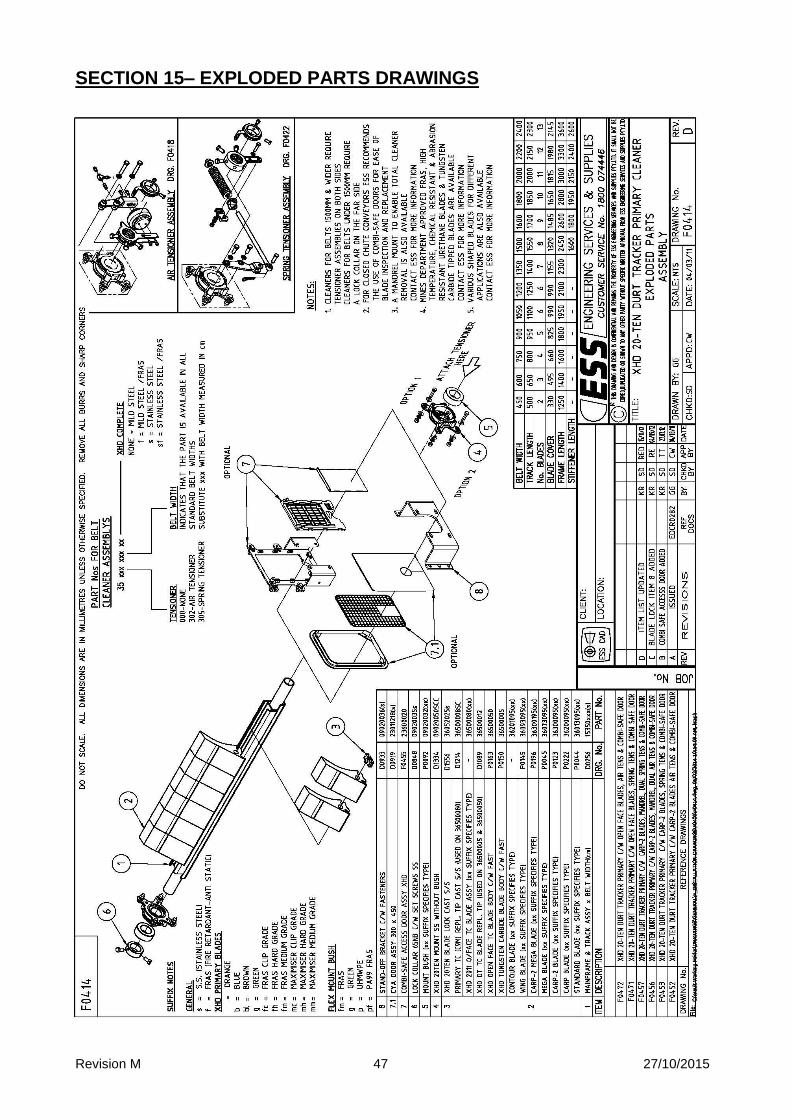
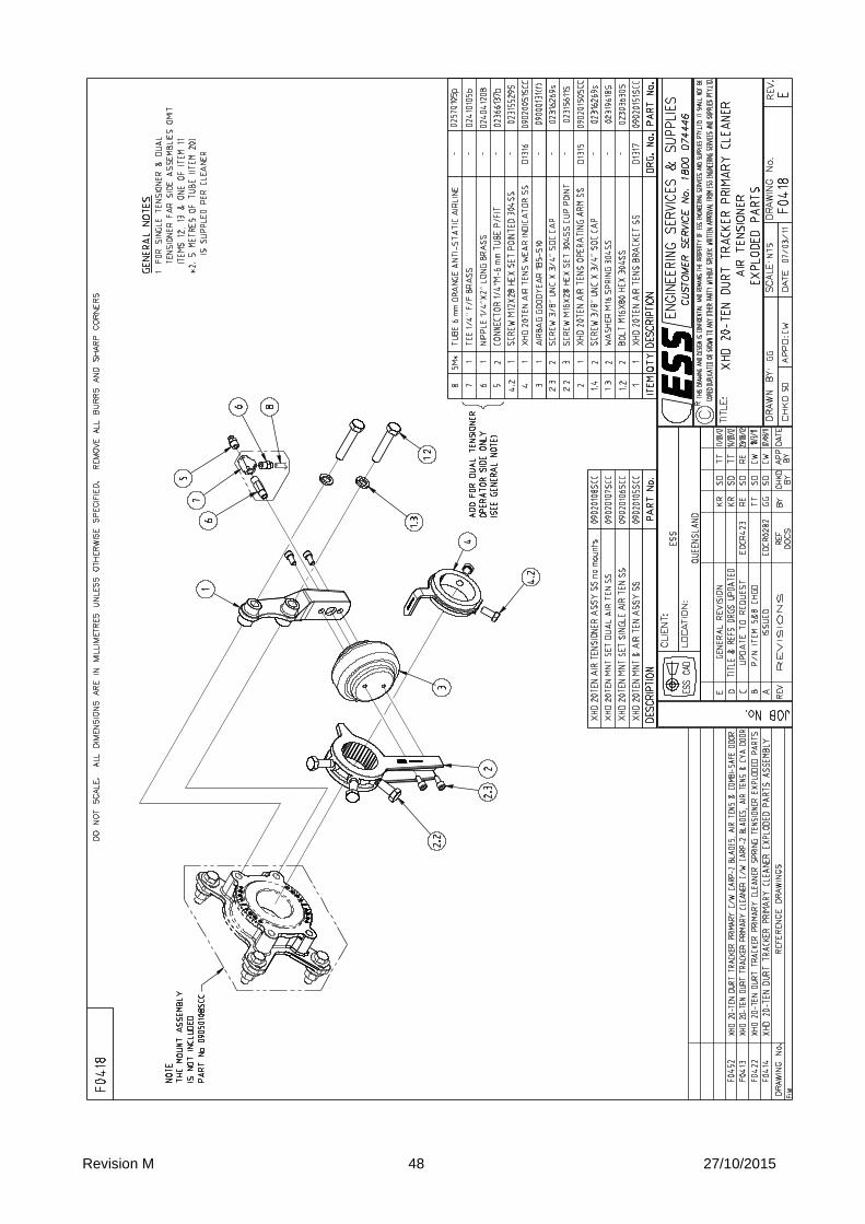
SECTION 15– EXPLODED PARTS DRAWINGS
Revision M 48 27/10/2015
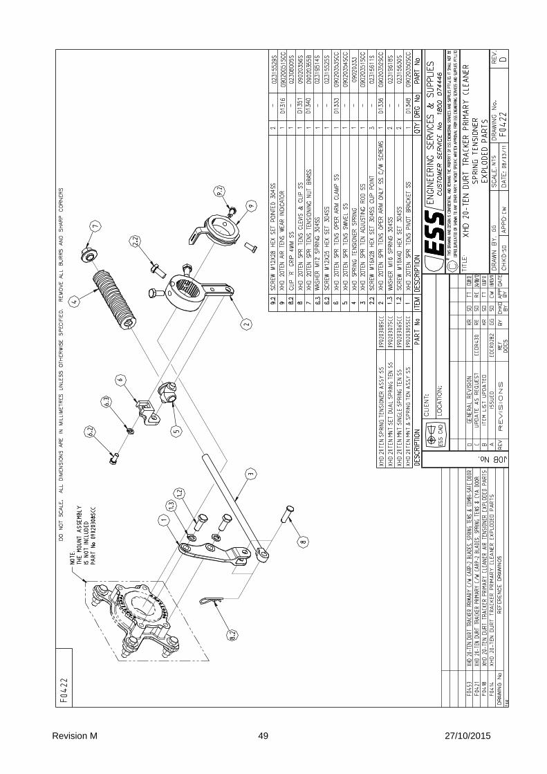
Revision M 49 27/10/2015
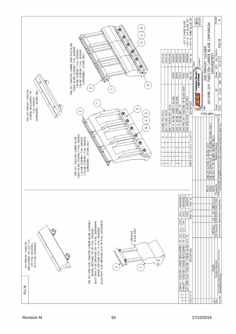
Revision M 50 27/10/2015

Revision M 51 27/10/2015
SECTION 16 FINAL CHECKLIST
Site: ____________________________ Number: _____________________ Date: ___________________ Site Equipment No./Location: _________________________ Site Contact: _________________________ Completed By: _____________________________________ ((CCiirrccllee YYeess oorr NNoo BBeellooww))
1. Was equipment to ESS Specification? _______________________________ Yes/No
Drawing No. Ref: _________________________________________Attached? Yes/No If No, WHY _______________________________________________________________________________ ________________________________________________________________________________________ Will this affect performance? Yes/No If Yes, WHY ______________________________________________________________________________ ________________________________________________________________________________________
2. Was this a standard service inspection installation? Yes/No If No, WHY _______________________________________________________________________________ ________________________________________________________________________________________
3. Was work carried out as per procedure and JSA? Yes/No If No, WHY _______________________________________________________________________________ ________________________________________________________________________________________
4. Is equipment fit for commissioning? Yes/No If No, WHY _______________________________________________________________________________ ________________________________________________________________________________________
5. Was a final inspection carried out while plant was running? Yes/No If No, WHY _______________________________________________________________________________ ________________________________________________________________________________________
6. Has anything changed from previous service / inspection / installation? Yes/No If Yes, WHAT _____________________________________________________________________________ ________________________________________________________________________________________
7. Is equipment performance to Client expectations? Yes/No If No, WHY _______________________________________________________________________________ ________________________________________________________________________________________ ESS Signature: ______________________________ Client Signature: ____________________________