
Xerox University Microfilms -...
129
THE LUNAR LASER RANGING POINTING PROBLEM Item Type text; Dissertation-Reproduction (electronic) Authors Carter, William E. (William Eugene), 1939- Publisher The University of Arizona. Rights Copyright © is held by the author. Digital access to this material is made possible by the University Libraries, University of Arizona. Further transmission, reproduction or presentation (such as public display or performance) of protected items is prohibited except with permission of the author. Download date 19/05/2018 00:39:20 Link to Item http://hdl.handle.net/10150/288113
Transcript of Xerox University Microfilms -...
THE LUNAR LASER RANGING POINTING PROBLEM
Item Type text; Dissertation-Reproduction (electronic)
Authors Carter, William E. (William Eugene), 1939-
Publisher The University of Arizona.
Rights Copyright © is held by the author. Digital access to this materialis made possible by the University Libraries, University of Arizona.Further transmission, reproduction or presentation (such aspublic display or performance) of protected items is prohibitedexcept with permission of the author.
Download date 19/05/2018 00:39:20
Link to Item http://hdl.handle.net/10150/288113
INFORMATION TO USERS
This material was produced from a microfilm copy of the original document. While the most advanced technological means to photograph and reproduce this document have been used, the quality is heavily dependent upon the quality of the original submitted.
The following explanation of techniques is provided to help you understand markings or patterns which may appear on this reproduction.
1. The sign or "target" for pages apparently lacking from the document photographed is "Missing Page(s)". If it was possible to obtain the missing page(s) or section, they are spliced into the film along with adjacent pages. This may have necessitated cutting thru an image and duplicating adjacent pages to insure you complete continuity.
2. When an image on the film is obliterated with a large round black mark, it is an indication that the photographer suspected that the copy may have moved during exposure and thus cause a blurred image. You will find a good image of the page in the adjacent frame.
3. When a map, drawing or chart, etc., was part of the material being photographed the photographer followed a definite method in "sectioning" the material. It is customary to begin photoing at the upper left hand corner of a large sheet and to continue photoing from left to right in equal sections with a small overlap. If necessary, sectioning is continued again — beginning below the first row and continuing on until complete.
4. The majority of users indicate that the textual content is of greatest value, however, a somewhat higher quality reproduction could be made from "photographs" if essential to the understanding of the dissertation. Silver prints of "photographs" may be ordered at additional charge by writing the Order Department, giving the catalog number, title, author and specific pages you wish reproduced.
5. PLEASE NOTE: Some pages may have indistinct print. Filmed as received.
Xerox University Microfilms 300 North Zeeb Road Ann Arbor, Michigan 48106

74-1993
CARTER, William Eugene, 1939-THE LUNAR LASER RANGING POINTING PROBLEM.
The University of Arizona, Ph.D., 1973 Engineering, civil
University Microfilms, A XEROX Company, Ann Arbor, Michigan
THIS DISSERTATION HAS BEEN MICROFILMED EXACTLY AS RECEIVED.

THE LUNAR LASER RANGING POINTING PROBLEM
by
William Eugene Carter
A Dissertation Submitted to the Faculty of the
DEPARTMENT OF CIVIL ENGINEERING
In Partial Fulfillment of the Requirements For the Degree of
DOCTOR OF PHILOSOPHY
In the Graduate College
THE UNIVERSITY OF ARIZONA
19 7 3

THE UNIVERSITY OF ARIZONA
GRADUATE COLLEGE
I hereby recommend that this dissertation prepared under my
direction by Will jam F P.artPr
entitled Thp lunar laser Ranging Pointing Problem
be accepted as fulfilling the dissertation requirement of the
degree of Doctor of Philosophy
L r/2 2/73 Date Dissertation Director
After inspection of the final copy of the dissertation, the
follov/ing members of the Final Examination Committee concur in
its approval and recommend its acceptance:
jri*i/73
5-IzzM
This approval and acceptance is contingent on the candidate's
adequate performance and defense of this dissertation at the
final oral examination. The inclusion of this sheet bound into
the library copy of the dissertation is evidence of satisfactory
performance at the final examination.

STATEMENT BY AUTHOR
This dissertation has been submitted in partial fulfillment of requirements for an advanced degree at The University of Arizona and is deposited in the University Library to be made available to borrowers under rules of the Library.
Brief quotations from this dissertation are allowable without special permission, provided that accurate acknowledgment of source is made. Requests for permission for extended quotation from or reproduction of this manuscript in whole or in part may be granted by the head of the major department or the Dean of the Graduate College when in his judgment the proposed use of the material is in the interests of scholarship. In all other instances, however, permission must be obtained from the author.
SIGNED:

Dedicated to my wife
Marilyn
and our daughters
Terri Lynn, Merri Sue, Pamela
iii
PREFACE
The author was employed as a Research Geodesist,
April 1969 through June 1972, at the Air Force Cambridge
Research Laboratories (AFCRL) Lunar Laser Ranging Observa
tory, Tucson, Arizona. Research funds were jointly provided
by AFCRL and the National Aeronautics and Space Administra
tion (NASA). Dr. Donald H. Eckhardt's (AFCRL) consultations
were most valuable to the author in both the theoretical and
experimental analyses associated with the laser pointing
problem.
Since July 1972 the author has been employed by the
University of Hawaii, Institute for Astronomy as the LURE
Project Manager. Project funding is provided by NASA
contract #NASW-2326, Dr. J. T. Jefferies, Principal
Investigator.
The author very gratefully acknowledges the many
valuable and pleasant associations with staff members of the
Lunar and Planetary Laboratory, Optical Sciences Center, and
the Physics, Civil Engineering, and Systems Engineering
Departments of The University of Arizona.
Very special "thank you's" to Dr. Elizabeth Roemer
and Professor Philip B. Newlin for their guidance,
patience, support, encouragement, and friendship, that made
it possible for me to complete this work.
iv

TABLE OF CONTENTS
Page
LIST OF ILLUSTRATIONS vii
ABSTRACT viii
CHAPTER
1. INTRODUCTION 1
1.1 General Historical Development of Lunar Laser Ranging 1
1.2 The Pointing Problem 7 1.2.1 Relevance 7 1.2.2 Accuracy Requirements 9
2. DEVELOPMENT OF POINTING EQUATIONS 11
2.1 Introduction 11 2.2 The Earth-Moon System 11 2.3 Topocentric Coordinate Systems 15 2.4 Angular Separation of Lunar Features ... 17 2.5 Atmospheric Refraction Effects 22
2.5.1 Introduction 22 2.5.2 Refraction Equations 23 2.5.3 Differential Refraction 25
2.6 Velocity Aberration 26
3. POINTING UNCERTAINTIES 34
3.1 Introduction 34 3.2 Lunar Coordinates 35
3.2.1 Introduction 35 3.2.2 Surface Features 35 3.2.3 Target Coordinates 38
3.3 Earth Related Errors 39 3.3.1 Introduction 39 3.3.2 Observatory Coordinates 40 3.3.3 Polar Motion 45 3.3.4 Time 46
3.4 Instrument Errors 48 3.4.1 Introduction 48 3.4.2 Optical System 49 3.4.3 Mechanical System 53
v

vi
TABLE OF CONTENTS—Continued
Page
3.5 Atmospheric Effects 66 3 • 5 • 3. Seeing 66 3.5.2 Refraction Correction
Uncertainties 68 3.6 Feature-Related Factors 70 3. 7 Conclusions 71
3.7.1 Relative Pointing Methods 71 3.7.2 Absolute Pointing Methods 71
4. EXISTING U. S. SYSTEMS 73
4.1 Introduction 73 4.2 McDonald Observatory Pointing Systems ... 73 4.3 Smithsonian Astrophysical Observatory
System 76 4.4 Air Force Cambridge Research
Laboratories Systems 78 4.4.1 Introduction 78 4.4.2 Two-Telescope System 79 4.4.3 Single Telescope System 87
5. UNIVERSITY OF HAWAII LURE OBSERVATORY 90
5.1 Introduction 90 5.2 Description of the Transmitter and
Pointing System 93 5.2.1 Introduction 93 5.2.2 Lunastat 95 5.2.3 Feed Telescope 96 5.2.4 Relative Pointing System 97 5.2.5 Absolute Pointing 104
6. REVIEW AND SUMMARY . 105
LIST OF REFERENCES 107

LIST OF ILLUSTRATIONS
Figure Page
2.1 Earth-Moon System 12
2.2 Selenocentric System 18
2.3 Transformation of Offsets to Hour Angle-Declination System 19
2.4 Celestial Sphere 30
4.1 Auxiliary Telescope Tracker-Guider System ... 83
4.2 Single Telescope System 89
5.1 University of Hawaii Laser Transmitter System 94
5.2 Lunastat System 101
5.3 Offsets in Lunastat System 103
vii

ABSTRACT
Lunar laser ranging is a recently developed tech
nique that permits accurate measurement of the distance
between Earth based observatories and retroreflector arrays
on the Moon. Current technology allows range resolutions of
a few centimeters, sufficient to allow the study of
phenomena significant to a variety of disciplines including
celestial mechanics, geophysics, physics, and geodesy.
Currently available lasers have beam divergence and
energy output limitations that make it necessary to use a
telescope to expand and collimate the outgoing laser pulse
and to collect returning photons, in order to achieve a
workable signal to noise ratio. Pointing of the trans
mitting telescope requires the most stringent accuracy—
approximately 1.0 to 1.5 arcseconds (RMS).
Errors in pointing arise from inadequacies of both
theory and instrumentation. The magnitude and significance
of the various errors may be independent or dependent upon
the basic technique and particular instrumentation used.
Two basic methods, each admitting variations of specific
techniques may be denoted as "absolute pointing" and
"relative (differential) pointing." The dominant error
sources are quite different for the two methods.
viii

ix
Starting from the basic geometrical relationships of
the problem, the mathematical structure of the problem is
developed. The parameters required to formulate the problem
are examined in order to determine the uncertainties in
their evaluation, providing an estimate of the uncertainties
resulting from inadequacies of theory.
The physical parameters that require measurement
during the actual process of pointing are identified, and
the general measuring techniques and instrumentation are
examined. An attempt is made to arrive at reasonable
estimates of currently technologically feasible accuracies
in the measurement of these parameters—yielding the
uncertainties resulting from inadequacies of instrumenta
tion.
The analysis leads to the conclusion that it should
be possible to limit the "typical" pointing uncertainty to
0.5 to 1.5 arcseconds (RMS) using relative pointing methods.
Extensive testing of a system developed at the AFCRL Lunar
Laser Ranging Observatory verify the precision (repeata
bility) of relative pointing, but a lack of sufficient range
data makes it impossible to infer the system accuracy.
Expected pointing uncertainties for absolute
methods are found to be very dependent upon the structural
flexure peculiar to the individual instrument, but generally
increase with aperture. Current technology limits the use
of absolute pointing methods to small aperture instruments,
X
less than about 60 cm diameter, for which it appears
possible to reduce uncertainties to 1 to 3 arcseconds (RMS).
A system of 40 cm aperture, designed by the author,
is currently under construction by the Institute for
Astronomy, University of Hawaii, at the Mt. Haleakala
Observatory complex, Maui, Hawaii. The system will have
instrumentation for both relative and absolute pointing
methods, designed for optimum expected performance based
upon the analysis and conclusions presented in this thesis.

CHAPTER 1
INTRODUCTION
1.1 General Historical Development of Lunar Laser Ranging
The historical development of laser ranging to
points on the moon from earth-based observatories (lunar
laser ranging) to gather information applicable to
geodetics, geophysics, relativistic physics, and celestial
mechanics is rather complex and a complete, accurate,
indisputable attribution to the numerous contributing
researchers is likely impossible. One participating
researcher's recollections are detailed in Alley (1972).
It is clear that the technique is rooted in the
explosive development of electronic distance measuring
technology spawned by World War II, and that many scientists
from several countries have made significant contributions
to formulating the basic concepts and developing these
concepts into operational methods.
In 1941 a Swedish Geodesist, Eric Bergstrand con
ceived a new technique to measure the speed of light
(Laurilla I960, p. 194). Bergstrand used an electro-optical
shutter (Kerr cell) to modulate the light from an ordinary
incandescent light bulb. The modulated light was then
collimated and projected by a parabolic mirror to a distant
1
2
cube corner array, where a portion was retroreflected back
to the instrument, collected, and directed to a photo-
multiplier for detection. The round trip travel time was
measured by a phase comparison technique. Knowing the
instrument-reflector separation allowed Bergstrand to
compute the speed of light. If it is assumed that the
speed of light is known, it is obvious that the technique
can be used to measure an unknown distance. In 1947 the AGA
Co. (Svenska Aktiebologet Gasaccumulator, Stockholm-Lidings)
licensed by Bergstrand, marketed their first production
instrument called a Geodimeter—name derived from the words
GEOdetic Distance METER. The basic instrument has since
been continually modified and improved. The more current
models use a HeNe gas laser as the light source.
In 1957 the first U.S.S.R. Sputnik was lifted into
orbit. Researchers in various disciplines recognized the
enormous potential of close orbit satellites to gather
previously unobtainable data. A whole new branch of geodesy,
known as satellite geodesy, developed (Mueller 1964). Early
techniques utilized the satellite as a "target" which was
visible, because of its high altitude, from widely separated
points on the Earth's surface. Satellites such as the Anna
series were equipped with light beacons of sufficient
brilliance to be recorded by geometric cameras from several
widely separated Earth stations simultaneously. When the
satellite was photographed against a star background it was

3
possible to determine its instantaneous topocentric coordi
nates. Simultaneous observations from two or more "known"
stations positioned the satellites and allowed observations
from unknown stations to be used to determine the precise
coordinates of those stations. In 1964 the first satellite
bearing an array of optical cube corners was put into orbit.
This satellite was subsequently sufficiently illuminated by
an earth-based laser to be photographed against a star
field, but the invention of "Q-switching" of ruby lasers
made possible techniques based on distance, rather than
directional, relationships between the satellites and
observing stations. Q-switching enabled one to produce a
very brilliant, very short pulse of monochromatic light.
The laser light could be collimated by a telescope, trans
mitted to the satellite, retroreflected to the sending
station, detected, and the round trip travel time measured
very accurately. Such ranging soon became routine. This
technique is not so very different from that of Bergstrand,
described above, and given the technological developments of
the intervening years, is a rather predictable extension of
the same basic principles. Certainly the thought of extend
ing the ranging technique to the Moon, our "natural satel
lite," follows directly.
Because of the relative remoteness of the Moon, it
was not immediately clear that lunar laser ranging was
within the then current technology or that significant

4
scientific contributions could be derived from such measure
ments. In April 1965, Rene Julian, Hughes Aircraft Co.,
undertook a feasibility study under an Air Force Cambridge
Research Laboratories Contract. His study (Julian, 1966)
was thorough and definitive, and concluded that the experi
ment was theoretically sound and feasible. During the same
period, in May 1955, a note in the Journal of Geophysical
Research (Alley, Bender, et al. 1965) suggested that the
lunar laser ranging technique could provide a long lived,
uncomplicated, passive device experiment, suited for
studying Earth-Moon physics. A formal proposal outlining
the experiment was submitted to NASA by the University of
Maryland in December 1965. Researchers from several insti
tutions contributed to this proposal (Alley, Chang, et al.
1965). These researchers subsequently organized themselves
into the Lunar ranging experiment (LURE) team.
During the ensuing months, both the AFCRL group and.
the LURE tea;?, worked with contractors on the development and
testing of suitable cube corner arrays. In March 1966 a
Russian team headed by Y. L. Kokurin published a paper
(Kokurin et al. 1966) detailing a ranging experiment in
which they had successfully detected Q-switched laser pulses
reflected directly from the Moon's natural surface. Natural
surface ranging is severely limited in accuracy due to the
lack of positional resolution, but the success of the
Russian experiment was important because it demonstrated
5
conclusively that a sufficient signal level to allow detec
tion could be attained even without the significant gain
expected from a cube corner array. In 1967 NASA assigned
the experiment a "Category I—develop for flight as soon as
possible" evaluation and in 1963 the experiment was selected
for the Apollo 11 flight. In January 1969 the LURE team
cube corner package was chosen by NASA for use, after an
AFCRL designed cube corner assembly failed testing. The
chosen package consisted of one hundred 3.8 cm diameter
aperture fused silica cube corners. The design, testing,
and expected performance are detailed in Alley (1971).
Four U. S. stations were made ready for ranging
operations: The AFCRL Lunar Laser Ranging Observatory,
Arizona; Lick Observatory, California; McDonald Observatory,
Texas; Mt. Haleakala Observatory, Hawaii. The Arizona and
Texas sites suffered poor weather during the period
immediately following deployment of the retroreflectors in
July 1969 and the Mt. Haleakala system proved inadequate for
the application. The Lick Observatory achieved the first
successful range measurements on August 1, 1969 (Faller
et al. 1969). McDonald Observatory was successful later in
August (Alley et al. 1969, p. 178) and the AFCRL site in
September (Bulletin Geodesique 1969). The Mt. Haleakala
and Lick sites had been planned for acquisition only, and
subsequently were shut down. Equipment problems plagued the
AFCRL station and only intermittent returns were recorded.

6
The station was closed in June 1972 and the equipment was
made available to an Australian team for relocation to that
country. After about a one-year shake-down period, the
McDonald Observatory system became fully operational and
presently averages more than 20 acquisitions per month with
an occasional success rate as high as "eleven evenly spaced
lunar range measurements over a nine and one-half hour
period" (Silverberg and Wiant 1971, p. 3). The Smithsonian
Astrophysical Observatory constructed a lunar ranging system
at Harvard Observatory, Massachusetts, which began ranging
attempts in 1971. After achieving a few range measurements,
lack of funding caused SAO to terminate the project.
In November 1970 French and U.S.S.R. teams cooperated
in the emplacement of a French built retroreflector package
on the Moon. The cube-corner array was mounted on the Luna
17 lunar rover vehicle—Lunahod I. U.S.S.R. and French
scientists reported (Kokurin, Kubasov, and Lobanov 19 73;
Orszag, Rosch, and Calame 1972) initial acquisitions but
have not been able to reacquire. Attempts to maKe range
measurements to the Luna 17 package by U. S. teams have been
unsuccessful, and it appears possible that the reflectors
were degraded by dust kicked up by the roving vehicle to
the point thab they are no longer functional. Two addi
tional U. S. retroreflector packages were placed on the
Moon by Apollo 14 and 15 missions. The units had 100 and
300 cube corners respectively. All three U. S.

7
retroreflector arrays are being used on a regular basis,
with no apparent deterioration. In January 1973 the
U.S.S.R. Luna 18 mission placed a second French-built
retroreflector package on the Moon. A cooperative effort
by a team of French and United States scientists led to
successful ranging on the unit, using the McDonald
Observatory system, on January 25. The signal level was
comparable to that of the Apollo 15 array. It is not yet
known if the retroreflectors will suffer significant
degradation during the exploration traverses of the
Lunahod II vehicle.
A second generation station is currently under
construction by the University of Hawaii, under a NASA
contract, on Mt. Haleakala, Maui, Hawaii. This new station
will utilize a subnanosecond pulsed NdYAG laser, dedicated
transmitting and receiving telescopes, and state of-the-art
timing electronics that have been designed to achieve a
range accuracy to + 100 p.ico-seconds (_+ 3 cm).
1.2 The Pointing Problem
1.2.1 Relevance
One important aspect of lunar laser ranging is the
accuracy of pointing of the transmitting and receiving
telescope (or telescopes) at the retroreflector. Unreliable
pointing not only reduces the number of measurements
obtained, but also limits information pertaining to'such

8
important questions as long term target deterioration,
target temperature and orientation effects on the signal
level, atmospheric limitations, minimum optical component
efficiency and related energy out requirements to achieve an
acceptable signal-to-noise ratio, and number of shots to
achieve a given statistical accuracy of range measurements.
These data become important when one tries to optimize
cost-efficiency of the experiment.
On a long term basis, a measure of the expected
target life is required to plan intelligently the number,
location, and level of funding of lunar laser ranging
observatories.
On a shorter term basis, it is important to know the
degree of degradation that optical components, including
such items as the laser rods, may suffer before the pro
ductivity of the system becomes seriously impaired and the
cost per measurement becomes unacceptable. If on a particu
lar night, the combination of weather conditions, equipment
conditions, and target cycle deterioration are such that the
expectancy of attaining a successful measurement is too
small, then it will be wise not to expend the laser life.
It is possible to measure such factors as atmospheric
transmission, seeing, reflectivity, and transmission of the
various optical components, but determination of correla
tions among them is made much more difficult, if indeed

9
possible, by a lack of knowledge about the pointing relia
bility .
1.2.2 Accuracy Requirements
Laser beam divergence, after collimation by a
transmitting telescope, can be reduced to a couple of
arcseconds or less. Assuming the atmospheric degradation
to be of the same approximate magnitude, the typical total
effective beam divergence would be approximately 3 to 4
arcseconds. If we assume that we are able to devise a
pointing method that is relatively free of systematic errors
and whose residual errors are normally distributed, 95%
reliability at the 1.5 arcsecond level would require the
standard error of a single observation (RMS) to be 0.75
arcsecond or less (Rainsford 1958, p. 3 2).
Two basic methods, each admitting variations of
specific techniques, may be denoted "absolute pointing" and
"differential (relative) pointing."
Absolute pointing requires that the apparent direc
tion of the target be determined in some topocentric
coordinate system, such as Altitude-azimuth (A,a) or hour
angle-declination (H,6) for times on a known time scale, and
that the laser light be transmitted in the proper direction
at that time.
"Differential pointing" deno tes a method where one
relates the direction of the retro reflector to that of some
10
identifiable lunar feature (or possibly a stellar image),
and using that direction as a fiducial, offsets to the
target area. Assuming a lunar feature is used, the offset
will be less than 30 arcminutes—the lunar angular diameter.
Both of these pointing methods will be investigated and
specific systems (hardware) will be described and analyzed.
The basic mathematics is presented in Chapter 2.
Sources of error involved in the pointing problem are
examined in Chapter 3. Pointing methods developed at
McDonald Observatory and at the Smithsonian Astrophysical
Observatory are described briefly, and two systems
developed at the Air Force Cambridge Research Laboratories
(AFCRL) Observatory are examined in detail in Chapter 4.
Chapter 5 contains a detailed description of a system
designed by the author and currently under construction at
the University of Hawaii Mt. Haleakala Observatory, that
will have both differential and absolute pointing capa
bilities. The author has made original contributions to
both the formulation and solving of the pointing problems
while working at the AFCRL Lunar Laser Ranging Observatory, .
Tucson, Arizona and at the University of Hawaii LURE
Observatory, Mt. Haleakala, Maui, Hawaii.

CHAPTER 2
DEVELOPMENT OF POINTING EQUATIONS
2.1 Introduction
Chapter 1 contained a brief history of the lunar
laser ranging experiment, described the pointing problem and
its importance, and briefly discussed methods of attacking
the problem, delineating in the process, two basic cate
gories of methods—absolute and differential. In this
chapter the mathematical structure of the problem is
investigated in some detail for both absolute and differen
tial methods.
2.2 The Earth-Moon System
Figure 2.1 is a sketch depicting the elements of the
Earth-Moon system significant to lunar laser ranging. At
any instant in time (T) the Earth center of mass to Moon
center of mass relationship is given by:
OM(t) = OL(T) + LT(T) - M T ( r ) (2.1)
Lunar laser ranging measures the distance (magnitude)
LT(t). This distance is
D2 = (EX.)2 + (£Y.)2 + (EZ.)2 (2.2) i l l
where X^, , Z^, designate the components of vectors
11
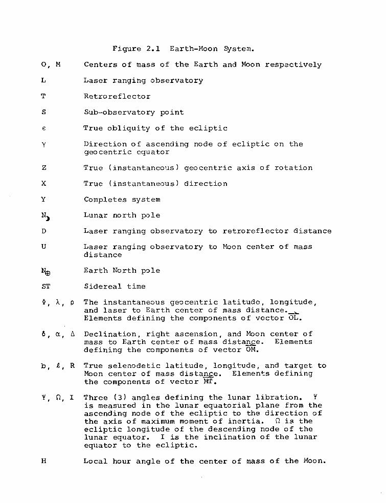
Figure 2.1 Earth-Moon System.
O, M Centers of mass of the Earth and Moon respectively
L Laser ranging observatory
T Retroreflector
S Sub-observatory point
e True obliquity of the ecliptic
Y Direction of ascending node of ecliptic on the geocentric equator
Z True (instantaneous) geocentric axis of rotation
X True (instantaneous) direction
Y Completes system
Nj Lunar north pole
D Laser ranging observatory to retroreflector distance
U Laser ranging observatory to Moon center of mass distance
Earth North pole
ST Sidereal time
X, p The instantaneous geocentric latitude, longitude, and laser to Earth center of mass distance. ^ Elements defining the components of vector OL.
6, a, A Declination, right ascension, and Moon center of mass to Earth center of mass distance. Elements defining the components of vector OM.
b, I, R True selenodetic latitude, longitude, and target to Moon center of mass distance. Elements defining the components of vector MT.
Y, Q, I Three (3) angles defining the lunar libration. Y is measured in the lunar equatorial plane from the ascending node of the ecliptic to the direction of the axis of maximum moment of inertia. ft is the ecliptic longitude of the descending node of the lunar equator. I is the inclination of the lunar equator to the ecliptic.
H Local hour angle of the center of mass of the Moon.

12
rCLIPTIC
X L U N A R \£ .QUA70R
X
Figure 2.1. Earth-Moon System.

13
1. OL 2. OM 3. MT. The components of vectors OL and OM can
be written directly by reference to Figure 2.1
OL
= p CO S$ CO S T
= pcos^sinT
Z^ = psins^
(2. 3)
OM
X2 = Acosficosa
Y_ = AcosSsina
Z^ = Asin6
(2.4)
The components of the vector MT in the geocentric (X^YjZ,)
coordinate system are not as readily obtained. Vector MT
is easily defined in a selenocentric coordinate system and
its components may be written as:
Xj = R cos b cos I
Y^ = R cos b sin SL
Zy = R sin b
(2.5)
It remains then to transform the selenocentric components
Xj, Yy , Zy , to geocentric components X^, Y^ , Z^. Examina
tion of Figure 2.1 will indicate that this may be done by
the following rotations:
X.
Y3 |= Rx (-e) Rz (-Q) Rx (I) Rz (-Y)| Y} (2. 6)
Z)
14
Equations (2.5) yield:
X^ = R cos b cos Z [cos Y cos Q - sin Y cos I sin fi]
- R cos b sin Z [sin Y cos Cl + cos Y cos I sin fi]
- R sin b sin I sin Q
= R cos b cos Z [cos e (cos Y sin fi + sin Y cos I
cos fi) + sin e sin Y sin i ] + R cos b sin cos e
(- sin Y sin + cos Y cos I cos Q) + sin e cos Y
sin i] + R sin b [cos e sin I cos 0 - sin e cos i!
= R cos b cos Z [sin e (cos Y sin 0 + sin Y cos I
cos fi) - cos e sin Y sin i] + R cos b sin Z [sin e
(- sin Y sin ft + cos Y cos I cos fl) - cos e cos Y
sin i] + R sin b [sin e sin I sin fi + cos e cos 13
{ 2 . 1 )
If all the parameters in Equations (2.3), (2.4), and
(2.7) were exactly known for the instant T, one could calcu
late appropriate , Z^ values, and Equation (2.2) could
be used to calculate D. Of course our knowledge of Earth-
Moon dynamics is not complete and what must actually be done
is to compute a best estimate value of D, using current
lunar theory, and compare this theoretical value to the
lunar laser ranging measured values. By analysis of
numerous measured-minus-theoretical differences (residuals)
made over an extended period of time, knowledge of the
various parameters of Earth-Moon physics may be improved.

15
The complexity of the relationships of the
parameters, for even a single instant T should be sufficient
to suggest the complexity of theory, the "lunar theory,"
required to describe the dynamic system. A number of
researchers have spent lifetimes at efforts to improve the
accuracy of the lunar theory and researchers at such
organizations as MIT, JPL, JILA today utilize the most
powerful computers in their attempts to perfect the
numerical models. Many Ph.D. dissertations have been
written on various facets of this problem. This disserta
tion concerns itself with the much more tractable problem
of optimizing the productivity of lunar laser ranging
stations, by reliably accurate pointing, thus providing
many points for comparison of theoretical and measured
values and hopefully helping the theorists to advance more
rapidly.
2.3 Topocentric Coordinate Systems
Two topocentric coordinate systems are of interest
in this investigation, Hour angle-declination (H,6) and
Altitude-azimuth (A,a).
The generation of a lunar ephemeris is generally
done in an inertial coordinate system and transformed to a
geocentric system. The immediate product is X, Y, Z values
for the center of mass of the Moon. The relationships
developed in Section 2.2 with the X, Y, Z coordinates of

16
the center of mass of the Moon as input, may be used to
compute the topocentric coordinate of points on the surface
of the Moon.
The X, Y, Z coordinates of Point T in an observatory
centered (topocentric) system are given by:
X2\ /X3\ /X1
Y2 ) + ( Y 3 ) " ( Y 1 * (2'8)
z2/ \z3/ XZ;L
The distance Df observatory to T, is given by:
D2 = + Yt2 + Z,r2 (2.9)
The topocentric a, 6, spherical coordinates are given by:
2+n sin 6 = -jj- (+ 28 > 5 > -28 )
YT ^T tan a = or Cotan a - (2.10) T *j, ~ ~ Y„
The topocentric coordinates (a, 6) may be trans
formed to the (H,6) system by the following rotations:
Rz (ST) | Y | (2.11)
H.6 " a.6
Where ST is the local sidereal time.
Coordinates in the hour angle-declination system
may be transformed to the Altitude-azimuth system by the

17
following rotations:
X
= Rz (-180°) Ry (90° - jzf) ( Y (2.12)
Z H.6
2.4 Angular Separation of Lunar Features
In Section 2.3 equations were derived to compute
(H,6) or (A,a) coordinates of a point on the lunar surface.
Angular separations between two points can be obtained by
differencing the respective vectorial coordinates. A
computer program developed by the author for computations of
offsets, using a dataphone connection to JOSS and Telcomp
time sharing systems, makes use of a somewhat different
technique. From topocentric coordinates of the subobserva-
tory point, i.e., the lunar surface point on a line from the
laser observatory to the Moon's center of mass, having
spherical coordinates b^, (lunar latitude, longitude)
predicted range and selenocentric direction cosines for the
target location and reference features, offsets can be
computed as detailed below. Figure 2.2 is a sketch of the
pertinent elements. (See also, Figure 2.3.)

18
LUNAR
MAJOR AXIS OF INERTIA
center of mass of the Moon.
vector from M to sub-earth point (intersection of lunar sphere and a line joining the laser observatory and M). The components of u are (cos b' cos , cos b' sin , „ • K \ u u' u u' sin /•
vector from M to target (retroreflector or topographical feature) on lunar sphere. The components of are cos b^ cos cos b^. sin sin b^.).
lunar north polar axis. The components of p are (0, 0, 1).
Position angle. Measured from to 1^. a. Jk Jk.
Dihedral angle, between planes containing u, p and u, t.
Figure 2.2 Selenocentric System

19
a = apparent angular separation of target from sub-earth point along perpendicular to u, p plane
b = apparent angular separation of target from sub-earth point in the u, p plane
x = apparent angular separation of target from sub-earth point in Hour angle
y = apparent angular separation of target from sub-earth point in declination
Figure 2.3 Transformation of Offsets to Hour Angle-Declination System

20
Derivation of Basic Equations for X-Y Offset Computations:
<LlL$l x = i slnE I t X u | |p X u I
u (t • (p x u)) = S |t x S| sin E = a
lp x "I
t • ( p X u ) . — 3.
|p x u|
T (-U ~ U , 0) (p x u ) —2 —1
Ip x u l (u2, + u?) 1/2
•1 —2 }
T JL. 2 —1 ®
a = t 1/2 . = -tl cos £u + ^2 s"*"n (2.13) + "J*
(t x u) - (P x u) = Cos E |t X u I |p X u
(t X u) • <j> x u) = |t x S| cos E = b
|p X U I
(t x u) = (t 2 u 2 ~ —3 —2 +
*—3 —1 ~ —1 —3 J +
21
(t x u) ' (p x u) = 2(—2 —3 —3 — 2 )
|p x u | / 2 2 v 1 (u1 + u2)
u_! <t_3 2L_i - t_! u_3> + 1 ^172 + °
(u^ + u2)
(U22 + U2^ ) (U 1 ) (U 3 )
b = t — t ~ , ,,, - t 3 9 9 1/2 —2 „ « 1/2 -1 0 „ 1/2
(Uj^ + u2) (u.^ + u2) (u^ + u2)
b = t 0 Cos b' - t ~ cos Z' sin b' —3 —2 u u
- t ^ sin sin b^ (2.14)
The angular offsets may be transformed to the x-y
system in the telescope focal plane, where x is essentially
the H component and y is the A6 component by a single rota-
tion about the u vector through the position angle (P).
>s (P) sin (P) R (P) u 1 1 * -Sin (P) Cos (P) 0/ Cos = ,ab,U
b sin (P) )
b co s (P) )
x = a co s (P) -
y = a sin (P) + b cos (P) J (2.15)
To compute the x-y intervals between two desired
points on the lunar surface (say the target and a guide
feature) one could compute a set of x and y values for each
point, and difference them.

22
Ax = Aa cos P - Ab sin P
Ay = Aa sin P + Ab cos P (2.16)
To convert Ax and Ay from units of lunar radius to
radians they must be multiplied by a scale factor, which is
the mean radius of the Moon divided by the current
observatory-Moon distance. It is convenient to use the
predicted round trip range, 2D .in units of light seconds.
The scale factor then becomes: 0-011595 Range
The Ax and Ay components computed by the procedure
presented above do not include refraction effects, optical
distortions, or velocity aberrations. These effects are
detailed below.
2.5 Atmospheric Refraction Effects
2.5.1 Introduction
Atmospheric refraction affects pointing in one or
more ways, depending on the particular pointing method being
used. The apparent zenith distance of the entire lunar disc
is reduced. But further, because the Moon is an extended
body, subtending an angle of approximately 30 arcminutes at
the Earth-Moon distance, features are differentially affected
as a function of zenith distance. This effect will be
referred to as differential refraction. Thirdly, since the
coefficient of refraction is a function of the wavelength of
light, a "chromatic refraction" correction may be necessary.

23
Consider an absolute pointing system. A refraction
correction should be applied for the laser wavelength and
the instantaneous zenith distance of the target. If one is
using an offset guiding method, the first-order term of the
refraction is automatically accounted for, but a differen
tial refraction correction is still necessary. Further, if
one is viewing the offset-guide feature or the target area
itself at a wavelength different from that of the laser, a
chromatic refraction correction is required. The differ
ential and chromatic refraction corrections are small com
pared with the nominal refraction correction and may be
thought of as second order effects. However, they can
individually exceed 1 arcsecond and must therefore be
considered for accurate pointing. The appropriate mathe
matical equations for computing the corrections are
presented below.
2.5.2 Refraction Equations
Determination of group refraction index by the
Barrel Sears Formula (Laurilla 1969):
(Ng - 1) (2.17)
A = 2876.04
B = 16.288
C = 0.131
\ = wavelength in microns

24
Determination of ambient refraction index by
Kohlrausch Formula (Laurilla 1969):
N = (n - 1) 10« - T -E- -5.5-10 8* e"| 6 ( , -1 ~ [l + at 760 1 + at J
P = barometric pressure in mm of mercury
e = partial pressure of water vapor in mm of mercury
a = thermal expansion coefficient of air
t = temperature in degrees centigrade
Determination of refraction by Smart Formula (Smart
1962):
R = A tan Z + B tan 3Z (2.19)
A = N(1 - H)
B = -N (H - N)
N is the index of refraction computed by Equation (2.18)
H is the ratio of the height of the homogeneous ^ atmosphere to the radius of the Earth ~ 1.4 x 10"
The formulas presented above are adequate for
observations at zenith distances smaller than 75°, suffi
cient for lunar laser ranging operations.
The refraction corrections may be applied directly
to the zenith distance, 90°-altitude, in an Altitude-azimuth
(A,a) system. If an hour angle-declination (H,6) system is
being used, the refraction affects both coordinates, except
at A = 0° or 180° when H is unaffected by refraction. The
corrections to be added to the topocentric H and 6 may be
25
computed to sufficient accuracy, by the equations:
I-R cos q jzf > 0
+R cos q jzf < 0
| -R sec 5 sin q 0*1 < H < 12*1
AH \ h b ( R sec 6 sin q 12 < H < 24 (2.20)
where q is the parallactic angle of the object observed and
R is the refraction (Woolard and Clemence, 1966, p. 92).
2.5.3 Differential Refraction
According to Section 2.5.2 refraction may be
expressed by Equation (2.19)
3 R = A tan Z + B tan Z
The differential refraction between two points on
the Moon of differing zenith distances would be given by:
4§ = A sec 2(Z) + 3 B tan 2(Z) sec 2(Z) (2.21) d A
For points on the Moon, AZ < 30 arcminutes and the
correction may be computed with sufficient accuracy using
approximation equations. Such equations are derived by
Woolard and Clemence (1966, pp. 92-93) for the more common
requirement of reducing observed quantities to geometric
quantities. We have geometric quantities and wish to compute
observable values. To the first approximation R = A tan Z.
Denoting the differences of geometric coordinates A, a, 6
by AZ = Z2 - Z^, Aa = (*2 - a^, A6 = 62 - 6-^ and the

26
differences of the observed values by AZ' = Z£ - Z|, Aa' =
- a|f A6 1 = 6^ - 6| we have
AZ' = AZ - (R2 - R )
= AZ - || AZ
AZ' = AZ - A sec 2Z AZ
. Ma - a1 ) , d(a - a1) .. Aa' = Aa 55; Aa ^ A6
A6' = 46 - S<63~ 8'- Aa - 3(6a~ A6 (2.22)
With Equations (2.20) and the setting d/dct = - 3/dH
d^da a—~ = ~ tan z cos <3 tan ® + tan s-'-n
^^ad6 a—~ = A S8C ^ (tan sin <3 cos <3 ~ tan z sin <5
tan 6 )
3 ( 6 - 6 ' ) * / , 2 „ . £ . . r7 • 1 \ ^ = A (tan Z sin q cos o + tan Z sin q sin 6;
3(6 - 61 ) „ . 2„ x = A (1 + tan Z cos q)
2.6 Velocity Aberration
Because of the finite velocity of light, the
apparent direction of the target as seen by the observer
is displaced by an amount, and in a direction dependent upon
the velocity of target relative to the observer. This dis
placement, known as velocity aberration, must be considered
in computing the direction in which the laser should be
pointed. The correction to be applied depends upon the

27
configuration of the instrumentation used, and the method of
pointing, relative or absolute.
Consider first a system in which the transmitter is
pointed by offset guiding on a visible lunar feature.
Assuming rectilinear motion of the Earth and Moon over the
time interval of the round trip light time, the relative
motion of the laser observatory and target may be described
by vectors. Julian (1966, pp. 47-60) investigated the
motions and the following closely parallels his work using
the notation developed above.
The motion may be separated into three components:
1. The orbital motion of the center of the Moon about
the center of the Earth.
2. The displacement of the retroreflectors arising from
libration of the Moon.
3. The displacement of the laser observatory by the
Earth's rotation.
Designating the vector displacement of the observa-
tory L relative to the target T by v
V = vOM + VMT ~ VOL (2.23)
where v^ is the displacement of the center of mass of the
Moon M from the center of mass of the Earth 0.
VMT "*"s < ;i-sPlacemen't °f the target from the
center of mass of the Moon.

28
vQL is the displacement of the laser observatory
from the center of mass of the Earth.
If Equation (2.23) is differentiated with respect to
time in an inertial coordinate system, it may be rewritten
in the form:
-ix. -iw V V = V0M + VMT ~ V0L (2.24)
-1 vOM as a ma9nitu<3e of 9 50 to 1100 m sec directed
along the Moon's trajectory.
-1 VMT *las a ma9nitu e °f less than 0.7 m sec in any
direction.
vQL is directed toward the East point of the
horizon and has a magnitude which is dependent upon the
latitude of the observatory and given (to 0.5 m sec"^) by
the equation
vL = 465 cos m sec-"'" (2.25)
The contribution of lunar libration vMT is insignificant and
the target may be considered as being at the center of the
Moon, with relative velocity given by:
V = vOM ~ vOL (2.26)
Formula (2.26) may be resolved into (H,6)
coordinates by reference to Figure 2.1, where L is the
laser observatory and M is the target at the center of the
Moon.

29
vr = vrm + vL cos 6 sin H
v_ = v., - v, cos H a am L
v. = v. - vT sin 6 sin H (2.27) 0 5m li
v , , v, , are the components of the Moon orbital rm' am' Om' ^
velocity. v , the velocity of the target along the radial
from the observer to the target, does not affect the pointing
problem. vL may be computed from Equation (2.25). 6, H may
be computed from Equations (2.8), (2.10), and (2.11). v am
and Vgm require further consideration.
From Figure 2.4 it is seen that
v_ = v. cos u am tm
v. = v. sin (a (2.28) Om tm
where v^m is the component of the Moon's orbital velocity
transverse to the Earth-Moon line. And from the right
spherical triangle NMQ
tan i-i = tan y cos 0 (2.29)
where Y is the inclination of the Moon's orbit to the
Earth's equatorial plane and 9 is the longitude of the Moon
measured from the ascending node of its orbit on the
Earth's equator. From the same triangle,
sin 6 = sin Y sin 0 (2.30)

Tj VERNAL
EQUINOX
z NORTH A POLE
Figure 2.4 Celestial Sphere

31
The velocity components may then be computed for
given values of vfcnif Y, and 8 as a function of H. A
peculiarity of lunar laser ranging is that both the
received and transmitted light are subject to aberration, so
in computing the direction in which the laser beam must be
transmitted relative to a guide feature, the actual relative
velocity must be doubled. The correct angular direction
correction in a, 6 components is given by
2v a a _ = a c
2v a c = 6 (2.31) 6 c
where c is the velocity of light.
The total magnitude is then given by
2 2 1/2 a = (a + a. ) (2.32) a o
If the system configuration is such that the same
telescope is used to transmit and receive the laser light,
the laser should "lead" the receive field stop by the
indicated amounts and directions. Since this is not very
convenient hardware-wise, the laser and receive optics will
usually be boresighted, in which case the aberration may
become, in times of excellent seeing, the limiting factor in
selection of the receiver field stop. In the case where
separate instruments are used to transmit and receive, only

32
the transmitter pointing must be corrected for velocity
aberration.
For systems that utilize absolute -pointing a ques
tion arises about the particular ephemeris used. Woolard
and Clemence (1966) state that,
No correction for aberration was applied to the ephemeris of the Moon computed from Brown's Tables of the Motion of the Moon. Aberration is not explicitly included in these tables; but apparently its principal effects were implicitly incorporated in the adapted values of the orbital elements. The further small periodic variations which should be included in a precise ephemeris were added in the national ephemeris beginning with 1960 (p. 139).
Second order effects include a periodic term with
an amplitude of approximately .04 arcsecond and a topocentric
correction term of 0.024 cos Z, both in longitude. These
corrections are too small to be significant to the lunar
ranging pointing problem. However, the diurnal aberration
must be taken into account. Equations (2.27) would thus
become, for absolute pointing, using Brown's (1919) Tables
of the Motion of the Moon
v„ = - vT cos H a L.
Vg = - vL sin 6 sin H (2.33)
More modern lunar ephemerides, such as the JPL (LE
series) and the MIT (Ash 1965), may or may not implicitly
include the aberration effects, and one should be careful to
find this out prior to their use, as the total correction is

approximately 1.4 arcseconds. Figure 6.2 in Julian (1966,
p. 51) is a graph of the velocity aberration correction for
a typical observing period.

CHAPTER 3
POINTING UNCERTAINTIES
3.1 Introduction
Chapter 2 developed the mathematical model and
equations reqiiired to compute theoretical apparent positions,
in topocentric coordinate systems, for lunar features. The
required parameters were assumed to be known without error,
and no mention of the expected errors, due either to theory
or instrumentation deficiencies was made. Chapter 3 under
takes the examination of the numerous sources of error with
the goal of at least enumerating the significant items and
examining them quantitatively with necessary qualifications
and constraints and arriving at some numerical estimates of
the pointing accuracies that can be achieved within the
limits of current theory and technology. Some of the error
sources are peculiar to absolute or relative pointing
methods, while others apply equally to both. Distinctions
will be made as appropriate.
34

35
3 , 2 Lunar Coordinates
3.2.1 Introduction
The pointing problem requires accurate coordinates
of lunar surface features and the retroreflectors in an
unambiguous coordinate system.
Astronomers are agreed that it would be advantageous
to use a coordinate system defined by properties of the Moon
itself, e.g., by identifying the axes of the coordinate
system with the principal axes of inertia of the Moon. The
axes would intersect at the center of mass of the Moon. One
axis would coincide with the lunar axis of rotation, the
remaining pair would lie in the equatorial plane with one
coinciding with the Earth-Moon radius vector when the Moon
stands at the mean ascending mode at perigee or apogee, and
the remaining axis would complete a right-handed system.
The selenocentric latitude and longitude would be analogous
to geocentric latitude and longitude.
3.2.2 Surface Features
The concept is quite straightforward, but the
realization of a truly selenocentric system is made diffi-
c\ilt because the system is not directly accessible for
measurements. The traditional approach has been to assign
fixed coordinates to some distinct feature near the center
of figure, thereby defining a fundamental reference point,
and then make differential measurements to various other

36
features. A limited number of measurements relative to the
fiducial feature define a triangulation network that pro
vides scale, orientation, and known points for network
densification. Observations by Franz, 1890-1894, using the
Xonigsberg Heliometer and his scalings of 150 points on Lick
Observatory plates were reduced by Schrutka-Rechtenstamm
1956-1958 to yield the Breslau selenodetic triangulation
network, which has been used as the basis for most subsequent
densification systems. The U. S. space program, with its
emphasis on lunar exploration, has created renewed interest
in increasing the accuracy and number of lunar features
coordinates. The more recent schemes include those of
Baldwin (1963), Meyer and Ruff in (1965), Gavrilov, Duma, and
Kislyuk (1967), Mills (1968), and Arthur and Bates (1968).
The coordinate systems are generally one of two
types, selenographic or true selenocentric. These terms
have been used rather imprecisely in the literature, but
will be used here to indicate systems that assume the lunar
features to be on a uniform sphere, and systems that con
sider the height of the individual features above or below
a reference sphere, respectively. Traditionally lunar
latitude (b*) and longitude (11) and direction cosines
(§, rl, C,) assume a sphere of unit radius and are related by
the equations:

§ = cos b' sin i'
V = sin b'
C = cos b' cos JL ' (3.1)
The (§, V) , Q) and (b'41 ) coordinates are not "true"
in that they are derived by assuming that the points are in
fact on a unit sphere. A projection to the sphere is
required, therefore, for those points differing in distance
from the coordinate origin. Since the viewing perspective
depends upon the librations, errors in the apparent position
will result. The magnitude of such errors depends on the
location of the point on the Moon, being least at the
center of the disk and increasing toward the limb. If one
assumed the relative position to be without error for zero
libration, the maximum error introduced by librational
effects would be approximately 0.10 arcseconds. The formal
standard errors for the coordinates show correlations with
the size of feature and its distance from the center of the
disk. If one chooses well-defined features of 10 to 20 km
diameter at distances less than 0.4 lunar diameter from the
center of disk the positional standard error (Arthur and
Bates 1958) is less than approximately 0.2 arcseconds.
Selenocentric coordinates (E, F, G,) are related to
the lunar longitude, latitude, and height (h) above a
reference sphere of radius r by

38
E = (r + h) cos b sin I
F = (r + h) sin b
G = (r + h) cos b cos 1 (3.2)
Where (r + h) = R in Equations (2.5) and b and I are the
true selenocentric latitude and longitude. The values
obtained from Equations (3.2) may be used as inpxat to
Equations (2.6). Arthur and Bates (1968) list selenocentric
coordinates for 1355 selected lunar features.
It must be remembered that the coordinate accuracies
quoted above were attained by photographic techniques, where
the image position may be measured very precisely on several
plates. Offset pointing for lunar laser ranging must be
done in real time and is subject to additional and/or some
what different error sources.
Distribution of measured features over the lunar disc
is quite adequate for lunar laser ranging purposes at nearly
all phases. Only near new moon, when one is forced to make
rather large offsets from points near the limb and contrast
in illumination drops rapxdly, is it difficult to find
suitable features. The difficulty encountered near new moon
is an important reason for developing an absolute pointing
capability.
3.2.3 Target Coordinates
The coordinate system used to locate lunar features
was discussed in Section 3.2. If such coordinates are to be
39
used to compute offsets to a retroreflector, the retro-
reflector coordinates must be accurately known in the same
system. The most obvious and practical way of obtaining
such coordinates is to locate the retroreflector relative
to local topography, in some manner.
Julian (1966) investigated the feasibility of
illuminating the retroreflectors with an Earth based laser
and photographing them against the lunar background. He
concluded that such a technique appeared to be feasible
under good seeing conditions. The method has not been
attempted since the retroreflectors have been placed on the
Moon as a part of manned Apollo flights and photographs
taken during the landing and by the orbiting command modules
have been available. Such photographs make it possible to
locate the retroreflector very precisely relative to the
local topography and only the inherent errors of the control
features are significant.
3.3 Earth Related Errors
3.3.1 Introduction
Equations (2.3) are based on the assumption that the
instantaneous orientation of the Earth in space and the
location of the observer relative to the instantaneous
absolute geocentric coordinate system are known without
error. This assumption is not strictly true. The rectangu
lar coordinates of the observer cannot be measured without

40
error. The orientation of the Earth's axis of rotation is
not constant, but undergoes secular, quasi-periodic and
random variations. This section will examine the effects of
such Earth-related errors on the lunar laser ranging point
ing problem. More specifically, since these errors are all
relatively small, of the order of a few to a few hundred
meters, they have no significant effect on relative pointing
methods, and only their effect on absolute pointing methods
will be examined.
3.3.2 Observatory Coordinates
Determination of the coordinates of points on the
physical surface of the Earth in some well-defined system
is the primary concern of applied geodesy. Such information
has importance to a wide variety of applications, e.g.,
boundary line determinations, geophysical studies, and
military operations, and societies have traditionally
expended national resources continually to increase the
number and accuracy of known points. In recent years space
technology has provided both the demand and the means for
determining the location of points relative to the center of
mass of the Earth—that is, in absolute geocentric coordi
nates (Carter 1972c).
The expected positional error for any point depends
upon the general geographic area in which the point is
located and the methods applied to locating the point. A

41
point located in the continental United States may be rather
easily and accurately tied to the North American Datum. The
North American Datum has been accurately located relative to
the center of mass of the Earth by satellite observations,
and the expected positional error ep, is thought to be 10
meters or less (Veis 1959). Stations located in less
developed areas of the world such as South America, Africa,
and large expanses of Asia are not so easily located with
comparable accuracy. Initial position uncertainties may
amount to several tens or hundreds of meters. Fortunately,
errors of this magnitude will cause a readily detected drift
in the range residuals (Faller et al. 1969), allowing the
derivation of improved station coordinates.
The range measurements, observatory to target
separations, require precise absolute geocentric rectangular
coordinates. But absolute pointing requires the establish
ment of a topocentric coordinate system relative to which
the instrument axes are oriented. The local vertical,
establishing the horizon plane, and a reference direction in
azimuth are observable quantities. Due to the asphericity
and nonhomogeneity of the Earth the local vertical, produced
as the straight line extension of the plumb line at the
station, will not generally pass through the center of mass
of the Earth. In order to compute the apparent position of
the target relative to topocentric (A,a) or (H,6) coordinate
systems, the relationship of the topocentric and geocentric

42
coordinate systems must be known. Assuming absolute geo
centric coordinates, the relative orientation, once deter
mined, will remain fixed except for minor local effects such
as periodic tilting of the vertical due to luni solar gravi
tational effects, tidal loading, and secular variations in
the vertical due to redistribution of masses within the
Earth. Tidal tilting has a maximum magnitude of approxi
mately 0.02 arcseconds. Rather large redistribution of mass
in the immediate vicinity of the station would be required
to cause a significant change in the local vertical. Such
redistribution could only be caused by readily apparent
events such as volcanic activities, or massive mining
activities. For practical purposes then, one can assume
that the topocentric coordinate systems will remain fixed
relative to the absolute geocentric coordinate system.
Astronomic latitude, longitude, and azimuth observa
tions yield instantaneous values, i.e., position and direc
tion relative to the instantaneous rotational axis of the
Earth. Classical geodesy has utilized astronomic observa
tions to establish the origin of datums and control network
distortions, by use of the LaPlace equations (Mueller 1968).
- f<G = e
UA - *.q) COS 0a = 7
aA - aQ = (XA - Xq) sin = ^tan (3.3)
43
where the subscripts A and G refer to astronomical and
geodetic values respectively, and e and are the deflection
components in the meridian and prime vertical planes
respectively.
The geodetic coordinates are relative to a particu
lar datum which assumes some Earth figure approximation,
usually an ellipsoid, and assigns values for:
A o = <*A - *G o o
= XA - XG o o
AH = Ha - H_ (3.4) O A vj
o o
The geodetic datum thus defined may not be con
centric with respect to the center of mass of the Earth.
The displacement of the center of the geodetic ellipsoid
from the center of mass may be determined from surface
gravity observations or Earth satellite observations
(Zakatov 1962, pp. 358-384; Mueller 1968, p. 28).
The uncertainties in the determination of and
\A have been investigated by a number of people. The formal
internal probable error for a set of observation (frequently
about 0.05 arcseconds or less) turns out to be an unrealis
tic index of the actual precision of the determinations.
Repeated independent determinations typically exhibit much
larger discordances. Bomford (1962, p. 281) has concluded
that the observed spread of repeated determinations can be

44
correlated qualitatively but not quantitatively, with
meteorological phenomena such as wind directions and
velocities and changes in the slope of the surfaces of equal
atmospheric density. Bomford (1962, p. 307) concluded that
time determinations at modern observatories are probably at
the 0.01 second of time, 0.15 arcsecond level, and field
determinations are likely to be about 0.02 seconds of time,
0.30 arcseconds (standard error). Latitude uncertainties
are of the same approximate magnitude (Bomford 1962, p. 386).
When combined with the uncertainties in the geo
centric coordinates the total uncertainty for each
component of the deflection would be approximately 0.3 to
0.5 arcseconds (standard error). The 95% reliability value
is approximately 0.6 to 1.0 arcseconds. Total uncertainties
are approximately 0.8 to 1.4 arcseconds for total deflection
of the vertical. For a permanent observatory where several
astronomic position determinations have been made over a
period of time and satellite observations have been made
from nearby stations, an uncertainty of approximately 1
arcsecond seems a reasonable assumption. The error intro
duced into the pointing direction depends upon the relative
directions of the target and deflections, and will have the
same effect as a dislevelment or tilt of the instrument.
A further complication arises in determining the
proper geocentric longitude to be used for lunar ranging.
McDonald ranging data requires, for best fit, the use of a

45
geocentric longitude differing approximately 0.7 arcseconds
from that obtained by direct tie to a nearby SAO satellite
tracking station. The difference represents an offset in
the "origin of longitudes."
Astronomic azimuths observed with astronomic
theodolites in low-to-moderate latitudes also have excellent
formal standard errors, but again repeated determinations
show wider spreads than expected. Extensive tests con
ducted by Northrop Corporation (Dieselman et al. 1969,
19 70) of North seeking gyros, indicated that even when a
considerable effort is made to maintain an accurate azimuth
reference, the reference will vary quasi periodically with
an amplitude of several arcseconds. The variations have
seasonal correlations, but the amplitude tends to vary and
occasional cycles are absent. Maintenance of an azimuth
reference at the one arcsecond level (95% reliability) would
require frequent redeterminations. The needed frequency of
such redeterminations would be expected to depend upon the
stability of the instrument pier, the instrument itself, and
the environment the system is exposed to.
3.3.3 Polar Motion
"Polar motion is the motion of the true celestial
pole (instantaneous rotation axis of the Earth) with
respect to a reference point fixed to the Earth's crust"
(Mueller 1968, p. 80). The observed motion is the resultant

46
of two periodic components, a 1.2 year revolution of the
true pole about the mean principal moment of inertia axis
in a counter clockwise direction, viewed from the North, and
a 1 year revolution in the same direction. The first
component is caused by elastic deformation of the Earth,
resulting in a displacement of the principal axis of inertia.
The second component is thought to arise from seasonal
redistribution of mass by meteorological and geophysical
processes. Additionally, there is some evidence that
suggests a secular term of 0.003 to 0.006 arcseconds per
year. The motion of the pole is determined by a network of
cooperating observatories, about thirty, located around the
world. The observations are used by the Bureau International
de L1Heure (BIH), located in Paris, to predict the coordi
nates of the pole.
Polar motion has an amplitude of a few tenths of an
arcsecond and may be predicted a few months in advance to a
few hundreds of an arcsecond. Discussions in Chapter 2 and
Section 3.3 specify that "true" geocentric coordinates are
assumed. The transformation from inertial to geocentric
coordinates must consider polar motion effects.
3.3.4 Time
Lunar laser ranging observations are made and
recorded relative to the observatory master clock. Range
measurements require both precise interval and epoch

47
information. VLF; Loran C, and portable clock visits are
used to relate the station clock to UTC. But the observa
tory is located on the rotating Earth and any observations
of celestial objects are made relative bo the instantaneous
pole and the Earth's rotational orientation relative to a
reference direction in space. Section 3.3.3 dealt with the
effects of polar motion. There remain variations in the
Earth rotational speed.
Three types of rotational variations have been
identified: seasonal periodic, thought to be due to
meteorological and Earth-tide effects; secular decrease in
rate due to dissipative tidal forces; and irregular fluctua
tions, thought to be related to solar activities (Marsden
and Cameron 1966; Munk and MacDonald 1960). The BIH pre
dicts the seasonal variations in the rotational speed and
its effect on Universal Time. The correction is designated
A\s and is given by
= a sin 2nt + b cos 2nt + c sin 4TTt + d cos 4trt
The coefficients a, b, c, d are determined empirically by
comparison of observations and precise atomic clocks. t is
the fraction of the tropical year from the beginning of the
Besselian year. The coordinates are determined and published
by the BIH and used by all coordinated time services to
determine UT2. Smaller terms with periods of 27.55 and
13.66 days, probably due to Earth tides induced by the Moon,

48
have also been identified and appropriate corrections may be
computed by the equations developed by Markowitz (1962,
p. 242).
Since January 1972, UTC is maintained at the funda
mental frequency of cesium, 9,192,631,770 hertz correspond
ing to the transition between the two hyperfine levels of
the ground state of the cesium atom of atomic weight 133
(Smith 1972, pp. 481-485). UT2 will drift relative to the
UTC scale. Positive or negative leap seconds will be
inserted as necessary, to maintain the difference at less
than 0.7 seconds. The correction to be applied to UTC to
obtain predicted UTO, the true instantaneous station time,
is therefore very significant and must be taken into account.
This effect is necessarily considered also in the transforma
tion from an inertial to a geocentric coordinate system.
The residuals may be expected to be a few milliseconds in
time, less than 0.1 arcseconds in the direction of pointing.
3.4 Instrument Errors
3.4.1 Introduction
A quantitative evaluation of the precision to which
an observer can center a telescope on a particular lunar
feature is indeed a complex and difficult task which, at
best, involves subjective estimates of precision. Signifi
cant parameters include the telescope aperture, design and
quality of the telescope optics, the character, definition,

49
and lighting of the particular lunar feature, atmospheric
effects, the telescope drive precision and guiding response,
the amount of tracking automation within the system, personal
influence (equation) of the observer. Some of these
parameters adnit to quantitative evaluation more readily
than others.
3.4.2 Optical System
3.4.2.1 Telescope Resolving Power. The theoretical
diffraction limited resolving power (0) of a telescope is a
function of its aperture (D) in cm and the wavelength of the o
light being observed ( X ) in Angstroms and is given by the
following equation (Jenkins and White 19 57, p. 304)
9 = • 10~3 (3.6)
0 is the angular separation in arcseconds of two images that
results in the central maximum of one diffraction pattern
and the first dark ring of the other diffraction pattern
being coincident in the telescope focal plane. The
effective resolution for offset guiding can be no better
than the diffraction limit for the telescope aperture and
will in general be somewhat less due to atmospheric seeing
and to deficiencies in the optical design and fabrication.
Several aberrations due to the optical design
increase with angular separation from the optical axis. In
order to provide a sufficient field to allow offset guiding

50
over a reasonable range of lunar phase angles, a field
radius of 15 arcminutes (approximately equal to the lunar
angular radius) is required. Two-mirror large aperture
reflecting telescopes have significant aberrations, such as
coma, astigmatism, curvature of field, and distortion that
can limit the resolution to a few arcseconds at points 15
arcminutes off axis. Even the relatively wide-field
Ritchey-Chretien design exhibits approximately one arcsecond
of astigmatism at that field angle. Catadioptric systems,
which combine reflective and refractive elements, can pro
vide better off-axis resolution. The difficulty and costs
of fabricating very precise optics increases rapidly with
aperture and field.
The ability of an observer to "center" on an image
depends not only on the optical resolution of the system,
but also on the image contrast. For high contrast
symmetrical images, such as a star viewed against the dark
sky, one can center a reticule on the Airy disc to a frac
tion of the disk diameter. Centering on lunar features
cannot be achieved with comparable accuracy. The contrast
is much lower and the blurring due to the limited resolution
further reduces contrast. The "edges" of features lose
definition, with the consequence that the limit of precision
of centering becomes much more nearly comparable with the
effective resolution of the system.

51
3.4.2. 2 Reticle Selection. The accuracy with which
an observer can center on a lunar feature will be affected
by the design of the reticle used. The variety of reticles
is dependent only upon the imagination of the draftsman,
within such technical limitations as minimum line width and
separation. Several types of reticles have been tried for
lunar ranging. Insufficient data are available for a
meaningful evaluation of their relative success and it is
quite possible that the single most important factor may be
individual observer preference. Trials of reticles at the
McDonald Observatory have included several configurations
ranging from computer drawn fiducials with short crosshairs
oriented toward the target area, to a simple single set of
crosshairs. The author has found crosshairs with short "tic"
marks at intervals of 2 to 4 arcseconds, beginning at the
center and extending several intervals along each line to be
versatile and convenient.
3.4.2.3 Aberrations. If a system uses offset
guiding as the pointing technique, errors arising from
optical aberrations must be considered. The type and magni
tude of the aberrations present in a given optical system
are a function of the type of system involved, e.g.,
Ritchey-Chretien, classical Cassegrain, refractor, as well
as any imperfections of the particular instrument used;
i.e., in general the optics will not conform to the

theoretical figures with sufficient exactness to allow use
of the theoretical aberrations. Distortion, which causes a
nonlinearity of scale in the focal surface, is of particular
concern in offset tracking. Fortunately, the focal plane
scales for the moderate to large aperture telescopes used
for lunar ranging are rather large, in the range of 1 mm
equals 10 to 30 arcseconds. Precise x-y coordinate
comparators and positional stages are readily available that
have accurate runs of + 1.0 micron or better over several
centimeters of travel. Such comparators may be used to map
accurately focal plane distortion. Some care must be taken
to assure an adequate calibration, but RMS residuals of 0.1
to 0.25 arcseconds may be achieved (Section 3.4.3.1.4).
It is also important that any change in focal length
be considered, as the focal plane scale will vary directly
with such changes. Again this is a function of the
particular instrument used. For the relatively long focal
lengths common to most telescopes used in laser ranging,
scale changes will be insignificant over a focal length
range of several mm. If the figures of reflective components
are sensitive to temperature, significant changes in the
effective focal length and/or distortion may occur, and it
may be necessary to include an appropriate correction in
the computations of offsets.
3.4.3 Mechanical System
3.4.3.1 Axis Errors. The axis system on Alt
azimuth mounted telescopes consists of the opcical axis,
horizontal axis, and vertical axis. The mean horizontal
axis is the mean rotation axis of the horizontal axis system
resulting from a rotation in altitude. The mean vertical
axis is the mean rotation axis of the vertical axis system
resulting from a rotation in azimuth.
We may think of an XYZ orthogonal coordinate system
with the Z axis oriented to the local vertical, the instru
ment's vertical axis corresponds to the Z axis, the
instrument's horizontal axis to the Y axis, and the optical
axis lies in the XZ plane. In general the instrument will
not be in perfect adjustment, the consequence being a non-
orthogonality of the system. Due to imperfections of the
bearing systems, the actual departure from orthogonality
will vary with rotations of the axis systems. The mean non-
orthogonality of the axes is referred to as primary axis
error and the variations of the orthogonality during rota
tions, due to the mechanical deficiencies of the system, as
secondary axis error (Schwebel 1970, pp. 63-69).
Equatorially mounted' instruments have analogous
axes. The Hour-angle, or polar axis, i.e., the axis set
parallel to the Earth's mean axis of rotation, corresponds

54
to the Z axis, the declination axis to the Y axis, and the
optical axis lies in the X-Z plane.
3.4,3.1.1 Primary Axis Errors*.
The primary axis errors are defined as follows:
1. Primary optical axis error (c)
c = r - 90°, (3.7)
where r is the angle between the optical axis
pointing in the target direction and the left side
of the mean horizontal (declination) axis—as seen
in the target direction.
2. Primary horizontal (declination) axis error (i)
i = 90° - j (3.8)
j is the angle formed by the left side of the mean
horizontal (declination) axis with the mean vertical
axis pointing in the zenith (p^lar axis pointing at
the celestial pole).
3. Primary vertical (polar) axis inclination v (v, ay)
v" = S~ - z" (3.9) o
For an Altitude-azimuth system v is the difference of the
vector S for the mean vertical axis and the vector Z for o
the direction of local vertical and is given by the magni
tude v and the direction av; v is the angle between the mean
vertical axis and the zenith; and av is the horizontal angle
formed by the plane through the zenith and mean vertical

axis from some starting (reference) direction. For an Hour-
angle-declination system v is the difference of the vector S
for the mean polar axis and the vector Zq for the direction
of the celestial pole and is given by the magnitude v and
the direction av» Then v is the angle between the mean
polar axis and the instantaneous celestial pole and av is
the position angle, measured in a plane perpendicular to the
polar axis, beginning at 0° on the meridian and proceeding
eastward through 360°.
In many applications, in geodesy and fundamental
astrometry one can eliminate the effects of primary axis
error by the technique of instrument reversal; i.e.,
observations are made on the target with the instrument
direct and reversed and the mean of the measurements is
used. This technique is not applicable to the lunar ranging
pointing problem and it is therefore necessary to measure
the error, often a function of the direction of pointing of
the telescope, and apply appropriate corrections to the
encoder readings.
3.4.3.1.2 Secondary Axis Errors:
For a perfect axis system, the axis of rotation
remains spatially fixed relative to its guide during a
rotation. Due to imperfections in the physical components
of the axis system, the instantaneous axis of rotation will
not be identical to the mean axis of rotation, and these

56
deviations are denoted as "secondary axis errors." A more
precise mathematical definition can be developed as
follows. If we assume that no deformations of the axis
occur during a rotation, the axis of rotation is a straight
line relative to which all parts of the axis have an equal
angular velocity. Let the vector w denote the axis of
rotation. The instantaneous axis of rotation w^ is the
rotation axis during the incremental rotation d and is
defined relative to a cartesian coordinate system (x,y,z)
by the angles 0^, jzT gives the inclination of w^ to
the x,y plane and the orientation of the w^, z plane
relative to the x axis. The x,y,z coordinate system is
fixed relative to the axis guide. The mean axis of rotation
is denoted w and is determined as follows: The vectors w m m
and w^ form an angle r^ which is given by
cos r. = cos 0. cos d cos (Y. - Y ) + sin jzf - sin l I "m l m I m
(3.10)
The direction of the mean axis is defined by the vector w J m
for which [r r]^ = minimum. The instantaneous secondary
axis error is given by
w . = w. - w (3.11) si l m
Secondary axis errors usually have significant systematic
components with periodicities and amplitudes being functions
of the mechanical design. They are amenable therefore to
computer modeling and compensation (Schwebel 19 70, p. 90).

The magnitudes of the systematic secondary axis errors thus
become less significant and their reproducibility becomes
the most important consideration. Reproducibility here is
measured by the deviations in repeated determinations of
wg^ for identical axis-guide-bearing relationship; i.e.,
some error terms may have periods greater than 360°.
Secondary axis errors may rather confidently be designed to
be less than 1 arcsecond, and modeling residuals of 0.1 to
0.25 arcsecond RMS may be expected (Schwebel 1970, p. 158).
3.4.3.1.3 Stability Errors:
In the operation of a telescope, forces will be
exerted on individual instrument parts which, because it is
not possible to make a completely rigid structure, will
result in undesired motions of certain parts. For example,
when the instrument is driven in azimuth, a torque is
applied to the fixed substructure, causing some rotational
displacement relative to a fixed reference direction. The
shaft encoder, which is rigidly mounted to the substructure
cannot detect the motion, and the indicated azimuth is
therefore in error by an amount equal to the induced rota
tion. The magnitude and duration of the rotation may be
expected to be strongly correlated to the accelerations
associated with the telescope motions and the structural
characteristics of the particular telescope. Similar
stability errors are also caused by instrument imbalance
58
and differential temperature effects. Adequate structural
rigidity, balanced loading, and symmetry of construction are
important design considerations.
3.4.3.1.4 Angle Measuring Uncertainties:
Relative pointing requires the measurement of rela
tively small angles from reference lunar features or nearby
stars. The very nature of the method limits the practical
range of offsets to a few degrees; offsets of less than one
degree will strongly predominate. The desired angular
offset may be measured in the telescope focal plane by use
of an X-Y comparator or stage. The term X-Y comparator has
traditionally been associated with laboratory housed
measuring engines specifically designed for the scaling of
photographic plates to the highest accuracy. Recently, more
versatile devices, commonly referred to as positional
stages, have been developed and marketed for a variety of
uses usually industrial in nature, e.g., numerically con
trolled production of integrated circuits. The stages do
not attain the ultimate in accuracy characteristic of X-Y
comparators, but are much more ruggedly constructed, versa
tile, and less costly. The author will use the nomenclature
"X-Y stage" throughout the remainder of this discussion as
he interprets it as a more general terminology.
The X-Y stage is a mechanical assembly and will have
limited resolution and accuracy dependent upon the

59
imperfections of the various components. Ideally, the
stage should transport the eyepiece in two orthogonal axes
located in a plane parallel to the telescope focal plane.
The resolution, (Rs), of each motion of an X-Y stage in
angular units, e.g., arcseconds, is
R _ 206265 * (Resolution of Stage) , _ » S ~~ (Effective focal length of system)
Total positioning uncertainty is then J2. • Rs.
From Equation (3.12) it is apparent that increasing
the effective focal length of the offset guiding optical
system yields a better resolution. However, as the stage
range of travel increases the cost increases rapidly. For
example, current list prices for one manufacturer's stages
having 100, 150, and 225 mm travels are $2,480, $3,580,
and $12,420 respectively (Burnette 1972).
Two basic techniques are in common current use in
the design of precise X-Y stages. The stage is driven on
precision ways by screws. The stage position may be
measured by direct reference to precise drive screws or by
auxiliary devices such as scales or dial indicators which
are read optically or electronically. In the former design
the screws are rotated by measured amounts. The number of
screw rotations times the travel per rotation equals the
stage travel. The rotation is frequently measured by a
calibrated drum, as on a micrometer, or by driving the
screws with stepping motors and counting the accumulated

60
steps. Stages having resolutions and accuracies of one to
two microns over travels of 10 to 15 cm are commercially
available from Yosemite Laboratory, Berkeley, California
and Aeroflyte Corp., Pennsylvania (Burnette 1972).
Equation (3.12) indicates a minimum effective focal
length of 280 cm per micron of stage positioning uncer
tainty is required to attain an Rs = 0.1 arcsecond for a
1 micron resolution of stage. Precise stages are factory
adjusted and checked to insure orthogonality and flatness of
travel errors comparable to the basic positioning uncer
tainties. Total uncertainties may be maintained at the
tenth arcsecond level and therefore negligible. If the X-Y
stage is operated at varying ambient temperature it may
be necessary to apply a correction for scale changes due to
the expansion and contraction of the lead screws.
Absolute pointing requires the measurement of rela
tively large angles, tens or hundreds of degrees, which may
not be made by the previously described technique. Rota
tions of the mechanical axes must be measured and the
resultant direction of the optical axis deduced. Two basic
techniques are currently in use for the accurate measuring
of axis rotation—electro-optical and electronic.
Electro-optical encoders contain a precise binary
encoded glass plate fabricated in much the same way as are
theodolite circles. The plate commonly contains 15 or 16
concentric encoded channels that are read by an

illuminator-sensor system. Additional angular resolution is
accomplished by various electronic interpolation schemes.
Encoders having 19 or 20 binary bits (2.4 and 1.2 arcsecond)
resolution and accuracy are commercially available as
standard items. Encoders having 23 bit resolution and 21
bit accuracy have been designed. Unfortunately, the cost
increases rapidly as the resolution and accuracy require
ments become more stringent, and the estimated cost to
manufacture the first two 23 bit encoders is thirty-five
thousand dollars each.
Electronic encoders that measure shaft rotation by
purely electronic techniques to a resolution of 0.4 arc-
seconds and an accuracy of 1.0 arcsecond have been
developed and are currently marketed (Goerz Inland System
Division, Kollmorgen Corporation 1972). Sinusoidal input
currents are phase shifted by an amount proportional to the
angular relationships between the encoder body and central
shaft. The phase shift is measured to derive the absolute
angle of rotation. A 720 pole unit provides the resolution
and accuracy quoted above. Units having 1100 poles and a
resolution of 0.01 arcseconds have been made. The fully
electronic devices represent the current state-of-the-art
in angular positioning of instrument axes.
Both resolution and accuracies have been quoted
because the total system performance may be limited by
either. Accuracy tolerances refer to the true error in the
62
absolute angle indicated. Resolution refers to the smallest
measurable increment of rotation and the indicated angle
will normally be "reproducible," although in error, at the
level of resolution. The devices thus admit to calibration,
allowing absolute rotation .Tieasurements to be made accurately
to the level of resolution.
3.4.3.2 Drive System.
3.4.3.2.1 Drive Train:
The telescope drive precision and guiding response
affect the observer's ability to center on a lunar feature
and maintain center as the apparent direction of the Moon
changes. The observer may be thought of as the sensing
element in a closed loop servo system. The analysis of such
a servo system is beyond the scope of this study, but a few
remarks may be made. Several methods are used to drive
telescopes and it is important in trying to estimate the
attainable precision of track that one know the type of
system used. For example, one drive system design utilizes
a gear train driven by a stepping motor. Such motors are
designed to make one step, of uniform size, each time an
electronic pulse is applied. The number of steps per
revolution of the motor, and the gear train reduction,
define the angular displacement of the telescope axis for
each step. The minimum maximum error to which such a system
can track a moving object is 1/2 step in each axis, i.e., if

63
a sensor can detect when the error reaches 1/2 step and then
takes one full step in the appropriate direction, the error
will be 1/2 step in the opposite direction. To this minimum
error must be added such additional errors as sensor resolu
tion, response time, gear train non-uniformities and back
lash.
Another common drive system utilizes D.C. torque
motors either direct coupled or gear coupled to the tele
scope axes. Unlike stepping motors, torque motors are
essentially analogue devices. The drive rate is determined
by the current supplied to the motor. Tracking is accom
plished by varying the rate of the motor. A very tight
servo loop can be attained by such a system. The limiting
factor is generally the resolution of the rate sensing
device.
The servo loop will have some minimum time required
for the system to compensate for an out of tolerance
condition—the system response time. For example, a tele
scope is subject to wind loading. When the load is applied,
the telescope may be deflected from the desired pointing
direction by a rather large amount, due to backlash in the
drives and structural flexure. Some time will be required
for the sensor to detect the misalignment and generate a
correction signal. Time is required for the drive system
to reposition the telescope as directed. Additional time is
required for the sensor to detect that the alignment is

64
within tolerance. Particularly with large aperture instru
ments, response time may be as high as a few seconds, and
errors during this period may be as large as several arc-
seconds.
3.3.3.2.2 Automation:
Tracking lunar features may be automated to varying
degrees. The classification to techniques is analogous to
that of the basic pointing problem, i.e., absolute or
relative. An absolute system would be referenced to some
topocentric coordinate system in which look angles would be
set to correspond to computed values. A relative system
would take its reference directly from some visible object,
such as an illuminated lunar feature, from which computed
offsets would be set. Examples of such systems will be
described in some detail in Chapters 4 and 5. Attention
here will be limited to how the degree of automation affects
the tracking accuracy of an observer augmented system.
The motion of a lunar feature across the sky is very
complex. If one assumes that no automation is provided and
the observer must feed in all the information about the
motion by, for example, tuning in drive rates for each axis,
the task is a very demanding one. Due to such factors as
refraction, libration, velocity aberration, orbital position
of the Moon, telescope mount type, and telescope flexure,
the required drive rates will change continually. The range

65
of accelerations depends primarily upon the type of tele
scope mount used. For an hour-angle-declination system, or
"equatorial," the acceleration will be less than 0.1 arsec/
2 sec . An observer can cope adequately with such ratfes. If
an Alt-azimuth mount is used, the acceleration in azimuth
increases without bound in the zenith, and even at zenith
distances of several degrees an observer will have diffi
culty.
Equatorial mounts suffer distortions (flexures) as
the telescope changes orientation in the Earth's gravita
tional field. Large aperture equatorially mounted tele
scopes may exhibit several arcminutes of flexure. The
flexure can be mapped as a function of hour angle and
declination but residuals, even with the most sophisticated
models, are several arcseconds.
Alt-azimuth mounts typically have much less flexure.
The design leads naturally to a very symmetrical structure
and constant loading of structural components. The most
heavily loaded axis is oriented to local vertical and with
the instrument properly balanced the loading is pure thrust
and independent of the viewing azimuth. No thrust loading
is placed on the horizontal axis. The tube assembly and
mirror support are subjected to varying loadings and will
therefore be expected to exhibit some flexure. No large
aperture Alt-azimuth optical instruments have as yet been
put into operation (several are in various stages of planning

65
and construction) so operationally verified values are not
available, but a reduction of flexure by at least one order
of magnitude, as compared to an equal aperture equatorially
mounted instrument, may be expected. If it is feasible to
automate the tracking function either by the use of an
electronic sensor closed servo loop or by computer con
trolled pointing (Erickson, Tanner, and Fujii 1970) the
Alt-azimuth mount becomes more attractive, especially if
sufficiently accurate automated pointing can be attained
that the observer can be removed from the system.
3.5 Atmospheric Effects
3.5.1 Seeing
Atmospheric conditions also affect an observer's
ability to center on a lunar feature. The phenomenon
referred to as "seeing" causes the image to jitter and/or
blur. Seeing is caused by the existence of inhomogeneities
in the density of the atmosphere across the aperture of the
telescope. One may picture the column of air through which
the observations must be made as being composed of cells of
air, of various dimensions and indices of refraction, in
motion relative to the telescope aperture. The observed
effect depends on the size of the air cells relative to the
telescope aperture, degree of atmospheric inhomogeneity, and
effective velocity. In small aperture instruments, up to
about 25 cm, seeing will usually cause the image to jitter,

67
while remaining relatively sharp. The observer then has the
task of integrating the motion to arrive at the mean posi
tion. For larger aperture telescopes, where a number of
air cells may be passing across the aperture at any instant,
seeing will usually cause the image to blur or become fuzzy.
Depending upon the severity of the atmospheric conditions
the image may be seen to fluctuate from a sharp well-defined
condition to a small blur. The observer can usually "look
through" such seeing conditions, i.e., he can concentrate
on the image while it is sharp and ignore it when it blurs.
As seeing worsens, the sharpness at the best instant
deteriorates and the frequency of occurrence of good moments
usually dwindles. Under very poor seeing conditions, stellar
images may be seen to "explode" into many small discs whose
envelope may be tens of seconds of arc. For extended bodies,
such as lunar features, seeing degrades the contrast, and
the observer's ability to center is affected accordingly.
Seeing varies widely with location and may be quite local in
nature. Quantitative measurements of seeing require careful
explanations of how the measurements were made, including
the instrumentation used, and how the data were processed to
arrive at the seeing. The angular diameter within which 90%
of the total intensity of a 5th magnitude star is contained,
is one commonly used standard. Depending upon the aperture
of the telescope the distribution of the light within the
blur region may vary greatly with time. Investigations by

68
Brown (1960) and Nettleblad (1953) show that seeing worsens
with increasing zenith distance, z, approximately propor
tionally to sec ("jz)' Faller (1972) estimated that seeing
is seldom below one second of arc and more often than not
exceeds two seconds of arc at typical observatory locations.
The extent to which seeing degrades an observer's ability to
center depends on the telescope aperture, nature of the
seeing conditions, and observer experience and skill.
Depending upon the aperture of the instrument and
size of the air cells at the instant of transmission, the
laser pulse will either "walk" randomly about the reference
direcbion or be blurred, effectively increasing the diver
gence of the beam and reducing the intensity of the light
intercepted by the retroreflector. In either case, the
expected signal-to-noise ratio of the system will be reduced.
3.5.2 Refraction Correction Uncertainties
Another atmospheric effect that weighs on the
pointing accuracy is the departure of the real atmosphere
from the model used to derive the theoretical refraction
Equations (2.17), (2.18), and (2.19). Experience has shown
that the measured refraction will in general differ from the
computed theoretical value. Geodesists and astronomers
usually attempt to minimize the effect of such errors on
their observations by designing the observational program to
balance as much of the refractional effects as possible.
The observations are made as near to the zenith as feasible
and objects are often observed in balanced pairs, equally
distant in opposite directions from the zenith.
Lunar laser ranging does not admit to such proce
dures. However, if a relative pointing method is used, the
refraction error is "automatically" corrected for, at least
in the first order. The guide feature and target will be
directionally close and therefore suffer essentially the
same refraction.
If an absolute method is used, the refraction correc
tion becomes of more concern. Refraction equations such as
(2.19) are actually the most significant terms of truncated
series. The coefficients of the first two terms are nearly
completely determined by the atmospheric conditions at the
observing point. Higher order terms depend on the assumed
distribution of air densities with height, but for zenith
distances < 75° and any reasonable distribution model, the
theoretical refraction is practically independent of the
model chosen (Woolard and Clemence 1966, p. 85). However,
even at much smaller zenith distances, significant devia
tions from the theoretical values are regularly observed.
Local anomalies due to such factors as horizontal gradients
of pressure and temperature, and atmospheric turbulence,
occur frequently and vary rapidly. Surface meteorological
data cannot provide information about such effects, and "a
precise value of refraction for an individual observation
70
cannot be reliably determined" (Woolard and Clenence, 1966,
p. 89). These errors for a single shot may certainly be as
large as several arcseconds and even during relatively
stable atmospheric conditions may be several tenths of an
arcsecond (Bomford 1962, p. 281), large enough to contribute
directly to the pointing error.
3.6 Feature-Related Factors
The size, shape, definition, and lighting of the
particular guide feature selected will certainly affect the
centering precision achieved. Small, symmetrical, well
defined (sharp-edged, high contrast) features are, for
obvious reasons, the most desirable guide features. The
selection of suitable features is further complicated by the
striking change in appearance features undergo with lunar
phase, e.g., Figure 6.13 in Baker (1961, p. 99). Indeed,
an inexperienced observer will find it difficult to recog
nize rather distinctive features when viewed under different
lighting conditions. A feature may appear flat with soft
rounded edges and of very low contrast at one phase and deep,
steep walled, with high contrast at another. Such changes
in appearance make consistent centering difficult and
highly dependent upon observer skills.

3.7 Conclusions
71
3.7.1 Relative Pointing Methods
Relative pointing methods offer the simplest and
very likely the most accurate pointing. The previous
sections indicate that the most significant uncertainties
are the observer's ability to accurately center a reticle
on a lunar feature, the resolution and response time of the
observer-instrumentation servo loop, and the magnitude and
spectrum of disturbing effects.
During periods of relatively good seeing, 1 to 3
arcseconds, it appears likely that uncertainties of approxi
mately 0.5 to 1.5 arcseconds (RMA) may be achieved. If
seeing deteriorates to 5 to 6 arcseconds, the pointing
uncertainty may well equal or exceed the seeing.
3.7.2 Absolute Pointing Methods
Absolute pointing methods greatly reduce the impact
of uncertainties in personal equations of observers, but
they are subject to several sources of error that can be
circumvented by use of differential methods. Compensation
for atmospheric refraction effects, knowledge of the exact
target and observatory spatial relationship, measurement of
large angular rotations to orient the transmitter, all
become important and difficult considerations. Absolute
pointing below the 5 to 10 arcsecond (RMS) uncertainty level

72
is not currently technologically feasible with large
aperture instruments.
Small aperture instruments, less than about 60 cm,
specifically designed and constructed to the highest
attainable specifications may make pointing with uncer
tainties of 1.0 to 3.0 arcseconds (RMS) feasible. The
system described in Chapter 5, currently under construction,
should provide a much clearer understanding of present
technologically attainable pointing accuracies.

CHAPTER 4
EXISTING U. S. SYSTEMS
4,1 Introduction
Several relative pointing systems have been built by
the various organizations participating in the Lunar Ranging
Experiment. In this chapter we will survey briefly the
techniques and instrumentation developed for the McDonald
Observatory and the Smithsonian Astrophysical Observatory
(SAO) and will then discuss the AFCRL systems in much more
detail. Information on the McDonald Observatory and SAO
systems is a synopsis of numerous operational reports,
personal correspondence with staff members of the Observa
tories, and working visits to the Observatories. Informa
tion concerning the AFCRL systems comes directly from the
author's design, development, and operational experiences
with the systems.
4.2 McDonald Observatory Pointing Systems
A group at the McDonald Observatory has been making
range measurements on a regular basis since August 1969.
The laser is coupled into the telescope and guiding is per
formed from the coude room. The 107 inch telescope has
computer controlled drives with shaft encoder readouts.
Programs have been written to provide absolute pointing at
73

74
celestial objects, including the Moon and, more specifically,
selected points on the lunar surface. The accuracy of
absolute pointing is severely limited by structural flexures
of the massive telescope assembly. For lunar laser ranging
an observer guides visually on a lighted feature and applies
minor corrections to the computer generated pointing.
Without auxiliary optics, the coude field was only a few
arcminutes in diameter. Visual guiding could be used only
when the target was in or near the lighted portion of the
Moon. The desired offsets were made by means of specially
prepared reticles inserted into the focal plane. The
reticles consisted of feature outlines at proper relative
orientations and separation for the appropriate librations
and range. The reticles were generated by a computer pro
gram. The system suffered from limited offset range and
from the fact that the reticles were only exactly correct
for an instant, and changes occurring over the period of a
measurement were significant. Correction for atmospheric
dispersion and velocity aberration required the observer to
offset the reticle slightly on the guide feature. A certain
amount of "searching" was required to acquire the target,
and the number of measured returns was notably dependent
upon the observer and the magnitude of the offsets required.
When the target was in the dark portion of the Moon
and the offset to a lighted guide feature was too large for
the limited field of view, a different technique was used.
75
The telescope was pointed at a reference feature and then
offset, using the encoders, by an appropriate amount to be
pointed at the target. The computer control continued to
drive the telescope at the computed lunar rate in order to
"track" the target. The flexure problem was then reduced to
a differential one, but the encoder errors were significant.
Even though the target efficiency and background level should
result in a greatly improved signal to noise ratio for lunar
night measurements, relatively few acquisitions were made by
this technique. Clearly, the pointing accuracy was not as
good as with the previously described technique.
In February 1971 a new pointing system was installed
at the McDonald Observatory. The new system utilizes a
precise X-Y stage to measure the offsets. Auxiliary optics
have been installed to provide a larger field of view,
approximately 15 arcminutes. The stage is rotated about the
optical axis by clock drives to compensate for the coude
image rotation. Some difficulties involving calibration of
the stage were encountered, but these have apparently been
solved, and a marked improvement in the number of successful
measurements has been achieved during lunar phases requiring
relatively large offsets.
A very useful innovation tried and proven with the
McDonald pointing system was the installation of cube corner
reflectors at the exit aperture of the transmitting tele
scope, in order to retroreflect a portion of the transmitted

76
beam. If a selected cube corner is used, the reflected beam
is true, directionally, to a fraction of an arcsecond. The
reflected laser light appears as a small dot in the focal
plane of the telescope, having an angular diameter of 5 to
10 arcseconds depending upon the laser beam divergence and
the cube corner aperture. The true transmitted direction of
each pulse is therefore readily observed. Once the
stability of the laser is confirmed, a small HeNe gas laser
may be superimposed on the p\ilsed laser to provide a con
tinuous fiducial in the observer's field of view. The
system has proven to be accurate, reliable, and convenient,
and was adapted to the AFCRL system also (Carter, Eckhardt,
and Robinson 1972, p. 179).
4.3 Smithsonian Astrophysical Observatory System
A group at the Smithsonian Astrophysical Observatory
(SAO) built a lunar laser ranging system based on the opera
tional philosophy that measurements could be made from a
number of stations most economically if a relatively small,
transportable transmitter was used in conjunction with
already existing moderate-to-large aperture telescopes as
receivers. The transmitter could be co-located on a
temporary basis, at an observatory where time on a suitable
telescope was available.
The transmitter developed is described in some
detail by Lehr et al. (1972). The major components are a

77
high powered (20 joules or more) Neodymium-Glass frequency
double Q-switched laser, timing and control electronics, and
a refracting coude telescope of 21-cm aperture. The tele
scope has a polar axis mount (H,6) and is designed to allow
convenient change of the elevation of the polar axis over a
wide range, since its use at various latitudes was antici
pated. The tube actually contains two 21-cm aperture
refractor telescopes, one used for transmitting the laser
pulse and the other for pointing.
Pointing is done by the differential method of
offset guiding. A precise X-Y stage is mounted on the
backplate of the telescope tube. The offsets are measured
by dial indicators that record the X-Y traverses of the
stage. The two telescopes, transmitter and guider, are
boresighted by use of an offsetting retroreflector. The
retroreflector is placed in the path of the transmitted
laser pulse and a portion of the light is intercepted, dis
placed a sufficient amount to allow it to enter the guide
telescope, and exited parallel to the entering direction.
The alignment is checked periodically but correction cannot
be determined during actual ranging operations. The system
is relatively insusceptible to pointing errors arising from
flexure-induced boresight drifts, because it is a small
aperture instrument of low mass, and both telescopes are
fully integrated into a common, structurally stable tube

78
assembly. Further, refractors are inherently less sensitive
to component misalighment, another favorable characteristic.
Testing of the SAO system has suffered a number of
problems that have, at this writing, prevented the acquisi
tion of significant range data. The system operational
tests have been conducted at the Agassiz Observatory,
Harvard, Massachusetts. The number of nights of acceptable
weather conditions is small. The problem has been com
pounded by stringent FAA controls on allowable ranging
schedules due to the heavy air traffic in the Boston area.
Technical difficulties with the laser have made it necessary
to curtail the repetition rate of pulses, limiting the
number of actual shots fired even further. As a conse
quence, insufficient ranging attempts have been made to make
any meaningful evaluation of the operation's pointing
accuracy.
4.4 Air Force Cambridge Research Laboratories Systems
4.4.1 Introduction
Upon completion of a feasibility study (Julian 1966)
steps were taken under sponsorship of AFCRL to establish an
observatory in anticipation of the eventual emplacement of
retroreflector arrays on the iMoon. The system would have
the interim capability of ranging to the natural surface.

79
A suitable site was located at the Lunar and
Planetary Laboratory (LPL), The University of Arizona,
Catalina Observatory, near Tucson, Arizona. Contracts were
entered into with The University of Arizona for construction
of a telescope and observatory, and with Hughes Aircraft
Inc. for the design, fabrication, and installation of a ruby
laser system complete with logic, control, and timing
electronics and directly compatible with the LPL telescope.
The AFCRL Lunar Laser Ranging Observatory began
operations in 1969 and development continued until the Air
Force terminated the project in June 1972. Two different
ranging systems were developed during the life span of the
project. The following sections will discuss the two
systems in considerable detail, with emphasis on those
factors pertinent to the pointing problem.
4.4.2 Two-Telescope System
4.4.2.1 General Description. A 150-cm aperture,
metal mirror, infrared telescope costing approximately one
hundred thousand dollars had been developed for use in
research programs by LPL. A very significant reason for the
relatively low cost of this particular instrument was the
use of lightweight, inexpensive, metal optics of the
inverted Dall-Kirkham Cassegrain design, having a spherical
primary and an elliptical secondary mirror.

80
The design theoretically achieves a near diffraction
limited image on-axis, but coma enters rapidly at off-axis
field points, and at only one arcminute off axis the blur
spot from a point source is approximately 10 arcseconds in
diameter. Reference to the discussion in Chapter 3 should
make it obvious that such a telescope could not be used for
relative pointing methods over the target and guide
separations required for lunar laser ranging. The 150-cm
telescope could be used to collimate and transmit the out
going laser pulse, and to collect return photons for detec
tion by a photomultiplier tube, but pointing by offset
guiding required an auxiliary telescope.
Additionally, the 150-cm telescope did not have
accurate scales or encoders for even moderately precise
absolute pointing, since these are not needed in normal
astronomical observational work. An electronic tracker that
controlled both axis drives in a closed servo loop was
developed at LPL in an effort to meet the requirements of
the lunar ranging project. The tracker-sensor which is
further detailed in Section 4.4.2.3 shared the auxiliary
telescope optics.
4.4.2.2 Total System Performance. The 150-cm
telescope and auxiliary guide-tracker systems were completed
in early 1969 and the laser system was installed in July
1969. Attempts to range on the natural surface of the Moon
81
near the subearth point were begun immediately. Attention
was shifted to the Apollo 11 retroreflector array immediately
upon its deployment.
A number of technical problems plagued the opera
tion. The metal optics never did provide the image quality
expected. Repeated attempts to construct a higher quality
set of 150-cm metal optics were unsuccessful. As a result,
the transmitted laser pulse had excessive divergence, in the
range of 7 to 15 arcseconds. Energy density at the retro-
reflector was correspondingly reduced, and the signal-to-
noise level was marginal.
The laser pulses were longer than the design specifi
cations; and the operating energy level had to be reduced to
prevent excessive damage to system components. Cooling pro
vided the laser was inadequate, requiring reduction of the
repetition rate. The net result was that the laser did not
provide the expected power output, and the signal-to-noise
problem was further aggravated.
The logic, control, power, and detector electronics
were all very unreliable, having a high rate of failure,
susceptibility to noise, and instabilities. Numerous hours
of observing were lost due to electronic malfunctions.
Pointing problems, largely due to inadequacies in
the mechanical and electronic components and flexure related
boresight drifts, were also encountered.

82
After it became abundantly clear that a major re
design and reconstruction of the system was required if
better than sporadic results were to be expected, the
Observatory was closed for approximately 9 months to effect
improvements.
4.4.2.3 Description of Auxiliary Telescope System.
Figure 4.1 is a schematic representation of the auxiliary
telescope tracking and offset guiding system. The basic
25-cm telescope is a Schmidt-Cassegrain type marketed by the
Celestron Company. The system has a focal ratio of 13.5.
The collected light impinged on a pellicle beamsplitter,
providing two images, one for electronic tracking and one
for offset guiding by an observer.
The electronic tracker used an ITT F4011 image
dissector tube having a 0.025-inm round aperture. The
aperture was electronically positioned by X-Y deflection
coils to view a desired area of the photocathode. The
same set of scan coils was used to generate an X-Y
orthogonal scan pattern corresponding to (H,6) components.
The scan was centered on a star or lunar contrasting feature
smaller than the full scan width. The output was processed
and the telescope driven to maintain balanced signal levels
on both the positive and negative portions of the scan in
each axiSo By changing the currents applied to the

Figure 4.1 Auxiliary Telescope Tracker-Guider System
1. Corrector Plate 2. 25 cm Primary Mirror 3. Secondary Mirror 4. Pellicle 3eamsplitter 5. Image Dissector Tube 6. Viewing Microscope 7. 150 cm Primary Mirror (Metal) 8. 25 cm Secondary Mirror 9. Transmit/Receive Mirror 10. Laser Diverging Lens 11. Viewing Eyepiece

83
C3
Figure 4.1 Auxiliary Telescope Tracker-^uider System

84
deflection coils, the image could be repositioned within the
field without exiting the track mode.
The image formed for offset guiding was viewed
through a microscope mounted on the X-Y stage. The stage
was positioned by use of dial indicators. The lunar image
was approximately 30 mm in diameter and the stage travel in
each axis was 25 mm. Gross repositioning of the stage was
accomplished by hand-operated wheels attached to the lead
screws. Variable rate clock drives were available for
correcting the eyepiece position to account for the slowly
varying offsets.
4.4.2.4 Experimental Results and Conclusions. It
has already been stated in Section 4.4.1 that due to the
inconsistent operation of other critical subsystems, it was
not possible to deduce the achieved pointing accuracy from
the return signal level. "However, a considerable effort was
made to determine the pointing precision.
The Apollo 11 site is located near the crater Moltke.
Moltke is a well defined, easily recognized crater with an
approximate diameter of 5.5 arcseconds or 6 km. The crater
was chosen as an appropriate fiducial to be used in
calibrating the offset guider in preparation of the Apollo
11 experiment. A system of approximately 40 craters and
peaks were selected as possible guide features. The list
was subdivided into several subsets consisting of 5 to 10

85
features that could be observed in a period of 4 to 5
minutes. The apparent X-Y coordinates of each feature of
the set were measured and the time of observation recorded.
Each set of measurements began and ended with the crater
Moltke, thus providing a measure of the tracking drift
during the measuring interval. Several hundred measurements
were made over the range of phase in which Moltke was
illuminated. These observations were used along with the
theoretical offsets to generate residuals. A Telcomp
library least squares program was used to find the best fit
plate scale and coordinate system orientation. The adjust
ment indicated a systematic difference in the scale along
the X and Y directions, and a small rotation of the stage
coordinate system. The program used to compute the offset
was modified to take these effects into account. The data
were also subdivided chronologically and adjusted using the
same computer program to determine the consistency of the
data and attempt to identify any systematic changes in
parameters that might be correlated with lunar phase angle,
declination, or altitude. An error in the application of
the refraction correction was found as a result of these
computations. The error was corrected and the adjustments
recomputed.
A few features had consistently high residuals.
After thorough rechecking of the system no correctable

86
causes were identified and these features were simply
eliminated from the list of guide features.
The residuals were examined further for correlation
with recorded estimates of the seeing. Seeing data con
sisted exclusively of observer estimates. For estimated
seeing in the 1 to 4 arcsecond range, no correlation was
found. For seeing worse than 4 to 5 arcseconds, residuals
were noticeably worse but highly inconsistent, i.e.,
repeated observations on the same feature yielded widely
differing residuals.
Eliminating observations made during periods of
seeing estimated to be worse than 4 arcseconds, the remain
ing observations were readjusted. The standard error of a
single observation derived from this final solution was 0.82
arcsecond.
This figure should be interpreted as a measure of
the precision or repeatability of offset guiding, and not a
measure of the accuracy. The observations were all made by
the author and therefore give no means to determine effects
of a personal equation. It was hoped that it would be
possible to correlate such measurements with return signal
strength to determine systematic errors. Unfortunately this
was precluded by unreliable performances of other system
components.
It appears that the auxiliary telescope system would
have been adequate for the pointing problem, except for the

87
flexure related changes in bore sighting relative to the
main instrument.
4.4.3 Single Telescope System
4.4.3.1 General Description. Based on the opera
tional experience gained with the initial AFCRL system, a
new system was conceived.
A new set of 150 cm optics was designed and
constructed. The new primary was a lightweight, center-
mounted, composite stainless-steel-CerVit assembly designed
to interface to the existing telescope body. The structural
design was the author's and is detailed by Carter (1972a).
The optical design was modified by R. A. Buchroeder, Optical
Sciences Center, The University of Arizona, from that by
Chre'tien (Buchroeder et al. 1972). The design provides a
30 arcminute field of view. The primary aberration is
astigmatism of magnitude approximately one arcsecond at
15 arcminutes off-axis. The design proved successful and a
brief report of the completed telescope imaging qualities is
given by Carter (1972b).
The high quality wide field made it feasible to do
offset guiding and tracking in the main field, thus
eliminating the requirement for an auxiliary telescope.
A newly designed laser was relocated at the top of the
declination cube, vacating the Cassegrain position for
installation of the offset guider. The laser receiver

83
package and offset guider and tracker units were interfaced
to the 152 cm telescope optics by means of a dichroic beam
splitter. Figure 4.2 details the system configuration.
4.4.3.2 Total System Performance. Prior to the
completion of the system the Air Force decided to terminate
participation in the lunar laser ranging experiment effec
tive June 30, 1972. The system was fully completed with
just three lunations remaining prior to the shut down date.
The laser still failed to perform to design specifications
and valuable time was lost in making further modifications.
Successful range measurements were finally made on two
consecutive nights in June on the Apollo 15 target. The
target area was lighted at the time and pointing was done
simply by observing directly the distinctive lunar
topography in the immediate vicinity.

Figure 4.2 Single Telescope System
1. 152-cm f/2.5 hyperboloid CER-VIT primary mirror.
2. 40-cm hyperboloid CER-VIT secondary mirror.
3. 23 x 15-cm elliptical dichroic beamsplitter (99% reflectivity at 694.3 nm).
4. 23 x 15-cm elliptical compensator plate.
5. 14-cm field lens.
6. 76-mm dichroic cube beamsplitter.
7. Nikkor-H 35-mm f/1.8 camera lens and portrait attachment.
8. Spherical aberration corrector plate.
9. Field flattener and reference reticle.
10. 40X microscope on X-Y stage.
11. Field flattener bonded to face of image dissector tube.
12. ITTF4011 image dissector tube.
13. Laser interfacing lenses.
14. Retroreflector.

89
Figure 4.2 Single Telescope System

CHAPTER 5
UNIVERSITY OF HAWAII LURE OBSERVATORY
5.1 Introduction
The University of Hawaii's Institute for Astronomy
is currently constructing a lunar laser ranging observatory
at the summit of Mt. Haleakala, Maui, Hawaii. The project
is funded by NASA under contract NASW-2326, with J. T.
Jefferies as Principal Investigator. The design, construc
tion, and operation of the station is being closely
coordinated with the LURE team and many of the major
components of the system are being built by D. Currie et al.
at the Department of Physics and Astronomy, University of
Maryland; J. Faller et al. at Wesleyan University and JILA,
University of Colorado; and by H. Plotkin et al., NASA
Goddard Space Center, Maryland.
Currie's group is developing a state-of-the-art
master clock that is capable of measuring the interval
between two events occurring within a few seconds of one
another to approximately 200 picoseconds. The clock will
be driven by a crystal oscillator and will be traceable to
UTC at the 1 to 3 microsecond level. The basic operating
principles are essentially the same as those developed by
E. G. G. Corporation and used in their Model TDC 100
90

91
interval timer. Additionally, the group is developing a
computer system, both hardware and software, that will
perform such tasks as generating precise range predictions,
recording the times of events provided by the master clock,
determining range residuals in real time and generating a
histogram of the recorded events on a CRT display, and
preparing data for transmittal to analysts. The computer
is a Nova 1200 (Data General Corp.).
Faller's group is building a unique multi-lens
telescope (Lurescope) to be used as the receiver. The
telescope, described in Faller (1972), consists of an array
of 80 achromatic objective lenses, each of 19-cm aperture,
mounted on a common faceplate. The light collected by each
element passes through a field stop, is collimated, and then
routed to a common lens, where the bundle is focused to form
the final image. The instrument has a collecting area
equivalent to that of a conventional reflecting telescope of
170-cm aperture.
The Lurescope has an Alt-azimuth mount. The
vertical axis has oil bearings, while the horizontal axis
has mechanical bearings. The drives are torque motors
coupled to the axes by metal rollers. Twenty-bit (1.2 arc-
second ) shaft encoders measure the rotations about each
axis. Pointing is done by the absolute method. The system
includes a Super Nova computer and associated software to
92
control the Lurescope. The same computer will be used to
control the transmitter and offset-tracker-guider function.
Plotkin's group is responsible for the development
of a siaitable laser. The laser is actually being
constructed by GTE Sylvania Inc., Electronic Systems Group,
Mountain View, California. The laser utilizes a design
developed by Sylvania under a previous contract from the
Office of Naval Research. It is a solid state frequency o
doubled (5320 A) NdYAG laser that outputs 200 picosecond
pulses (FWHM) of 350 millijoules at a repetition rate of
3 pulses per second.
The University of Hawaii's group is responsible for
the development of a suitable transmitter and associated
pointing system, detector package, construction and opera
tion of the observatory, and complete integration of the
various components into an operating system. The author is
the LURE Project Manager at the University of Hawaii and
heads a team of approximately nine scientists, engineers,
and technicians. The author has personally developed the
conceptual design for the transmitter and pointing systems,
drafted the technical specifications used in contracting
for system components, and designed, in detail, system
components to be built in-house.

93
5.2 Description of the Transmitter and Pointing System
5.2.1 Introduction
Figure 5.1 is a conceptual sketch of the laser
transmitter and pointing system. The collimated laser light
is routed by a turning prism to a diverging lens. The
diverging lens creates a diverging cone of light that
appears to emanate from a point lying in the focal plane of
the telescope objective. The diverging light is routed, by
reflection from a dichroic beamsplitter to the objective,
of 40-cm diameter. The objective recollimates the expanded
beam and transmits it toward the Alt-azimuth mounted
optically flat first surface mirror (Lunastat). The
reflected beam is directed by accurate positioning of the
flat, to exit the enclosing observatory dome through a
window of 30-inch diameter. A portion of the transmitted
beam is intercepted by a cube corner and retroreflected. A
portion (approximately 0.2%) of the reflected light passes
through the dichroic beamsplitter and is routed to the
pointing ocular which is mounted on a precise, computer
controlled X-Y stage used for pointing. The entire system,
including the laser, is mounted on a common rigid frame
concrete instrument pier.

Figure 5.1 University of Hawaii Laser Transmitter System
1. Dome Window
2. 68-cm Diameter (Afa) Mounted Flat
3. Retroreflector
4. Two Element 40-cm Diameter Objective
5. Dichroic Beamsplitter
6. Turning Mirror
7. Three Corrector Plates
8. Cube Dichroic Beamsplitter
9. Image Dissector Tube
10. Viewing Eyepiece
11. Laser Diverging Lens

94
Figure 5.1 University of Hawaii Laser Transmitter System

95
5.2.2 Lunastat
The Lunastat is being constructed by Goerz-Inland
Systems Division, Kollmorgen Corporation, Pittsburgh,
Pennsylvania. The design utilizes previously developed
units consisting of mechanical axis, direct coupled torque
motor drive, d.c. tachometer, and Inductosyn electronic
shaft encoder. The axis wobble is typically 0.5 to 1.0
arcseconds and the encoder has a resolution of 0.35 arc
second. Pointing uncertainty is double that of the basic
Lunastat positioning due to reflection. The electronic
logic, control, and readout units are standard production
items. Both manual and computer co ntrol modes are available.
A two axis electronic level is being built into the instru
ment to provide a real time measurement of tilt, and
appropriate corrections will be made in formulation of the
pointing commands.
A 70 cm diameter ultralight weight (56 pounds) fused
quartz optical flat, loaned for the duration of the project
by the Optical Sciences Center, The University of Arizona,
is the principal optical component.
The Lunastat design uses stabilized castings and
maximum symmetry of construction to minimize structural
flexure and temperature related distortions of the mount.

96
5.2.3 Feed Telescope
The principal imagery element of the feed telescope
is the 40 cm diameter f/11 achromatic objective. The two
elements of the objective are widely airspaced, by
approximately 20 cm, for the purpose of eliminating
spherochromatism. The objective is diffraction-limited,
monchroinatically, over the visible spectrum, and image
splitting by wavelength selection allows the objective to
be used simultaneously for three distinct piirposes—
transmitting laser pulses, visual viewing, and electronic
viewing.
The laser transmitting and two viewing optical paths
are interfaced to the objective by use of a 2.5-cm thick,
33-cm diameter fused quartz beamsplitter located approxi
mately 152 cm from the objective. The beamsplitter is
dielectric coated to have 99.8% reflection at the laser o
wavelength of 5320 A, and approximately 70 to 80% transmis-o
sion of the incident light in the 4000 to 5200 A region.
Light passing through the beamsplitter does suffer signifi
cant optical aberrations, and an array of three optically
flat corrector plates is used to compensate these aberra
tions. This light is further subdivided, by use of a
dichroic beamsplitter, and routed to an ocular and image
dissector tube mounted on the X-Y stage.
The feed telescope body and optical mounts are
being constructed by the University of Hawaii in-house.

97
The optical components are being fabricated by Hudson
Precision Optical Co. Inc., Hudson, New Hampshire.
The feed telescope optics were designed by R. A.
Buchroeder and are detailed by him (Buchroeder 1972).
5.2.4 Relative Pointing System
The feed telescope, described in Section 5.2.3, has
a nominal focal plane scale of 48 arcsec/mm, resulting in a
lunar image approximately 3.8 cm in diameter. A precise
X-Y positioning stage, purchased from the Yosemite Labora
tory, Berkeley, California is attached rigidly to the tele
scope tube and carries a package containing both an
observer eyepiece and an image dissector tube, ITT F4012 RP.
The stage is mounted on precision ways and is driven by
hand-lapped lead screws, which translate the stage 0.254 cm
per rotation. The screws are driven by stepping motors,
Superior Electric Inc. type LS50-1006, having 500 steps per
rotation with provision for half stepping. Each whole step
corresponds to approximately 0.22 arcseconds. If driven in
half step increments, the stage has a resolution of 0.11 arc-
seconds. The stage has been calibrated using a laser
interferometer with a resolution of 0.000254 mm. Maximum
deviation from linearity over the entire 10 cm travel, each
axis, is 0.0020 mm. Orthogonality of the axes is better
than 10 arcseconds and flatness of travel is better than
0.0020 mm over the entire travel. Total positioning

98
uncertainty over the full 10 cm x 10 cm field is less than
5 0.25 arcseconds. Temperature effects, about 1 part in 10
per degree C, are insignificant over a range of + 3 C
expected for the observatory ambient temperature.
Positioning of the stage may be controlled from a
manual control panel or by computer command. A one pulse
per rotation shaft encoder is mounted on each drive motor.
The total number of steps is recorded and the position is
inferred directly. Whole numbers of rotations are checked
for coincidence with the encoder pulse as a check against
loss or addition of spurious counts. The laser will be
aligned to the center of the stage travel as nearly as
conveniently possible, and the actual coordinates will serve
as fiducial. Offsets thus will be measured relative to the
laser coordinates. Star fields and lunar features will be
used to calibrate the focal plane distortions. The optical
design yields an effectively flat focal surface, but
fabrication deficiencies may result in significant devia
tions.
Use of two modes of relative pointing is anticipated.
The modes differ, however, only in the means used to
generate the basic lunar rate, i.e., by computer control or
electronic tracker control of the Lunastat. The first
method would use absolute pointing continually to update the
pointing, and the observer would be required only to apply
small corrections as required for deficiencies in the
99
pointing. It is the ultimate goal that computer pointing
be developed to the level of accuracy that the observer may
be eliminated from the system and truly absolute pointing
methods used. The second method uses an image dissector
tube, in much the same manner as the AFCRL system described
in Chapter 4, to lock on to a reference lunar feature. The
observer still must make small pointing corrections as the
offset changes with time. Comparison of electronic
tracking and computer pointing will be used to improve the
absolute pointing program model.
5.2.4.1 Lunastat Orientation. Discussion of the
coordinate transformations required to determine topocentric
(H,6) and (A,a) coordinates for lunar features, and deriva
tion of appropriate eqiiations for computing the apparent
angular separations of lunar features for a direct (H,6)
system were presented in Chapter 2. Mention was made in
Chapter 4 that the McDonald system, even though the basic
telescope mounting is (H,6)f had the complication of image
rotation as a function of hour angle because the observa
tions are made from a fixed coude position. The Lunastat
system described here may be characterized as a coude (A,a)
system. The mathematical expressions which describe the
required angular orientation of the Lunastat and the focal
plane image rotations become even more complex than for the
equatorial coude.

100
In Figure 5.2 the Lunastat is assumed to be located
at the origin of the (A;a) coordinate system. The vector M
is the desired pointing direction, with spherical components
(A,a). The vector T is the direction to the center of the
telescope reticle, taken to be colinear with but anti-
directional to the X axis, assuming the alignment to be
without error. L is the normal to the Lunastat flat mirror
and it is desired to determine the direction of L such that
the observer views an objected located at (A,a).
T + c" = M
„
c = M - T
M - T T + M L = T + C/2 = T + . = 1 +
T + M . ( 5 . 1 ) |L | |T" + M|
(X, Y, Z)f = (-1, 0, 0)
(X, Y, Z)^ = (cos A cos a, cos A sin a, sin A)
(y v 7)^- _ f (Cos A cos a^-1, Cos A sin a. sin a! t 9 T — o Q O . 1 / O
[ ( ( c o s A c o s a ) - l ) * + ( c o s A sin a) +(sin A) "J (5.2)
or
Al = sin-"'" Z
a^ = tan-^ Y/X
aL = cotan-^ y ^ (5.3)

101
Z (Zenith)
X (North)
Y (East)
Figure 5.2 Lunastat System
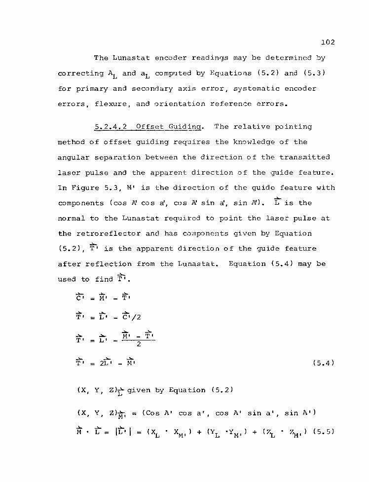
102
The Lunastat encoder readings may be determined by
correcting and a^ computed by Equations (5.2) and (5.3)
for primary and secondary axis error, systematic encoder
errors, flexure, and orientation reference errors.
5.2.4.2 Offset Guiding. The relative pointing
method of offset guiding requires the knowledge of the
angular separation between the direction of the transmitted
laser pulse and the apparent direction of the guide feature.
In Figure 5.3, M' is the direction of the guide feature with
components (cos A1 cos a', cos A1 sin a1, sin A'). L is the
normal to the Lunastat required to point the laser pulse at
the retroreflector and has components given by Equation
(5.2), T1 is the apparent direction of the guide feature
after reflection from the Lunastat. Equation (5.4) may be
used to find T1.
C~' = M' .w
- T'
T' = LT« - ~C' /2
T"
4 A II M". rn | — X
2
T' = 2L1 — M1 (5.4)
(X, Y, Z)^-given by Equation (5.2)
(X, Y, = (Cos A' cos a', cos A' sin a', sin A')
M • L = |L' | = (XL • XM. ) + (Yl .Ym, ) + {2^ ' ZM, ) (5.5)

103
Z (Zenith)
X (North)
Figure 5.3 Offsets in Lunastat System

104
XL,' = *L ' le' I \
YL. = I
= Vl?' I / (5.6)
5.2.5 Absolute Pointing
Every effort has been made to design in, within the
budgetary, technological, and scheduling constraints, an
absolute pointing capability with uncertainties less than
1.0 to 1.5 arcseconds (RMS). The Lunastat, feed telescope,
offset guiding assembly, and the laser are all mounted on a
single concrete rigid frame instrument pier. Electronic
levels are mounted in the base of the Lunastat, and their
outputs are readable by the computer. The observer's eye
piece is of the autocollimation type to allow precise align
ment of the Lunastat and feed telescope and a convenient
method to check the alignment stability. The electronic
tracker error signals and encoder readings will be recorded
along with timing information and compared with the computer-
generated pointing values. Meteorological instruments will
be read directly by the computer and used to compute refrac
tion corrections. Encoder errors and flexure will be
modeled.

CHAPTER 6
REVIEW AND SUMMARY
Reliably accurate pointing is required to optimize
the cost efficiency and the scientific productivity of the
lunar laser ranging experiment. Physical constraints and
present technological limitations require a pointing accuracy
of approximately 0.7 5 arcseconds (RMS).
Two basic methods of pointing, "absolute" and
"differential" may be denoted. Certain errors affect both
methods while others are peculiar to either absolute or
differential methods.
The mathematical structure of the problem is detailed
in Chapter 2, and the uncertainties that affect the two
methods of pointing are identified and evaluated in Chapter
3. The investigation concludes that sufficiently accurate
absolute pointing is not presently technologically feasible
with moderate to large aperture astronomical telescopes due
to large uncertainties arising from flexure. Expected
accuracies of relative methods are found to be 0.5 to 1.5
arcseconds (RMS) limited primarily by lunar phase angle and
atmospheric effects and observer personal equation uncer
tainties.
1 0 5

106
In Chapter 4, several relative pointing systems that
have been developed by research groups at McDonald
Observatory, Smithsonian Astrophysical Observatory, and the
AFCRL Lunar Laser Ranging Observatory are described.
Operational tests of the AFCRL system suggest an offset
guiding precision of approximately 0.8 arcseconds. Insuffi
cient range data are available to deduce the pointing
accuracy. A similar system is in use at the McDonald
Observatory, with satisfactory results. Unfortunately,
present techniques are not workable near new moon, a 6 to 7
day period in each lunar cycle. For this reason, develop
ment of absolute pointing remains attractive.
A second generation lunar laser ranging station is
currently under construction by the University of Hawaii,
Institute for Astronomy, at the summit of Mt. Haleakala,
Maui, Hawaii. The transmitter, which will include facilities
for both relative and absolute pointing is described in
Chapter 5. Present plans are for the system to be opera
tional by the end of the 19 73 calendar year.

LIST OF REFERENCES
Alley, C. O., 1971, Apollo Laser Ranging Retro-reflector Experiment, University of Maryland, Department of Physics and Astronomy, Final Report Contract NAS 9-7809.
Alley, C. 0., 1972, "Story of the Development of Apollo 11 Laser Ranging Retro-reflector Experiment," Adventure in Experimental Physics, 132-134, 137-149.
Alley, C. 0., Bender, P. L., Chang, R. F., Currie, D. G., Dicke, R. H., Faller, J. E., Kaula, W. M., MacDonald, C. J. F., Mulholland, J. D., Plotkin, H. H., Poultney, S. K., Wilkinson, D. T., Winer, I., Carrion, W., Johnson, T., Spadir, P., Robinson, L., Wampler, E. J., Wieber, D., Silverberg, E., Steggerda, C. , Mullendore, J., Rayner, J., Williams, W., Warner, B., Richardson, H., and Bopp, B., 1969, "Laser Ranging Retroreflector," Apollo 11 Preliminary Science Report NASA SP-214, 163-182.
Alley, C. 0., Bender, P. L., Dicke, R. H., Faller, J. E., Franken, P. H., Plotkin, H. H., and Wilkinson, D. T., 1965, "Optical Radar Using a Corner Reflector on the Moon," Journal of Geophysical Research, Vol. 70, 2267.
Alley, C. 0., Chang, R. F., Currie, D. G., Faller, J. E., Bender, P. L., and Poultney, S. K., 1965 (Revised February 11, 1966), "Laser Ranging to Optical Retro-reflectors on the Moon," University of Maryland Proposal to NASA.
Arthur, D. W. G., and Bates, P., 1968, "The Tucson Selenodetic Triangulation," Communication of the Lunar and Planetary Laboratory No. 131, University of Arizona.
Ash, M. E., 1965, Generation of the Lunar Ephemeris on an Electronic Computer, Massachusetts Institute of Technology, Lincoln Laboratory Technical Report 400.
Baker, R. H., 1961, Introduction to Astronomy, Sixth Edition, D. Van Nostrand Company, Inc., Princeton, New Jersey.
107

108
Baldwin, R. B., 1963, The Measure of the Moon, University of Chicago Press.
Bomford, G., 1962, Geodesy, Oxford University Press, London, England.
Brown, D. C., 1960, Results in Geodetic Photogrammetry II, RCA Data Processing Technical Report 65.
Brown, E. W., 1919, Tables of the Motion of the Moon, Yale University Press, New Haven.
Buchroeder, R. A.; 1972, 16-inch f/11 Refractor Lunar Laser Transmitter System, Design Report prepared for University of Hawaii, Institute for Astronomy.
Buchroeder, R. A., Elmore, L., Shack, R. V., and Slater, P. N., 1972, "The Design, Construction, and Testing of the Optics for a 147-cm-Aperture Telescope," Optical Sciences Center Report 79, University of Arizo na.
Bulletin Geodesique, 1969, 94, 443.
Burnette, R., 1972, "Yosemite Laboratory Technical Brochure and PMCR List."
W. E., 1972a, "Lightweight Center-Mounted 152-cm f/2. 5 Cer-Vit Mirror," Applied Optics, Vol. 11, 467.
W. E., 1972b, "Timing and Geodesy," Proceeding of IEEE, Vol. 60, No. 5, 610-613.
W. E., 1972c, "Operational Tests of the AFCRL 152-cm Telescope," Applied Optics, Vol. 11, 1651.
W. E., Eckhardt, D. H. , and Robinson, W. G. , 1972, "AFCRL Lunar Laser Instrumentation Status Report," Space Research XII, Akademie-Verlag Berlin, 177-186.
Dieselman, J., McLaughlin, R., Millo, K., and Fitzgerald, C., 19 69, "Gyrocompassing and Astro Azimuth Measurement Results," Report No. PPD-69-E-10275, Northrop Corporation, Electronics Division, Norwood, Massachusetts.
Dieselman, J., McLaughlin, R., Millo, K., and Thompson, L. B., 1970, "Recent Developments in the Testing of High Performance Gyrocompass Devices," Northrop Corporation, Electronics Division, Norwood, Massachusetts.
Carter,
Carter,
Carter,
Carter,

109
Erickson, J. D., Tanner, P., and Fujii, C., 1970, "An Advanced Automatic Telescope Control Program," Report of the Mt. Haleakala Observatory No. 1386-27-T.
J., 1972, "The Apollo Retroreflector Arrays and A New Multi-lensed Receiver Telescope," Space Research XII, Akademie-Verlag Berlin, 211-217.
J., Winer, I., Carrion, W. , Johnson, T., Spadin, P., Robinson, L., Wampler, E., and Wieber, D., 1969, "Laser Beam Directed at the Lunar Retro-reflector Array: Observations of bhe First Returns," Science, Vol. 166, 99.
uavriiov, I. V., Du.ua, A. S. , and Kislyuk, V. S. , 1967, "Catalogue of Selenocentric Positions of 500 Basic Points on the Moon's Surface," Figures and Motion of the Moon, edited by A. A. Yakoukin.
Goerz Inland System Division, Xollmorgen Corporation, 1972, Technical Brochure.
Faller,
Faller,
Jenkins, F. A., and White, H. E., 1957, Fundamentals of Optics, Third Edition, McGraw-Hill Book Company Inc.
Julian, R. S., 1966, Feasibility Study of Laser Ranging Systems, Prepared for Air Force Cambridge Research Laboratories, Office of Aerospace Research, United States Air Force, Bedford, Massachusetts, Contract AF19(628)-5172.
Kokurin, Y. L., Kurbasov, V. V., and Lobanov, V. F., 1973, Space Research XIII, Akademie-Verlag, Berlin.
Kokurin, Y. L., Kurbasov, V. V., Lobanov, V. F., Mosherin, V. M., Sukhanovakiy, A. N., and Chernvkh, N. S., 1966, JETP Letters, Vol. 3, No. 5, 139.
Laurilla, S. H. , I960, Electronic Surveying and Mapping, Institute of Geodesy, Photogrammetry and Cartography No. 11, Ohio State University.
Laurilla, S. H. , 1969, "Statistical Analysis of Refractive Index Through the Troposphere and Stratosphere," Bulletin Geodesique No. 92, 132-153.

110
Lehr, C. G., Pearlman, M. R., Monjes, J. A., and Hagen, W. F. , 19 72 , "Transportable Lunar-Ranging System~ 11
Applied Optics, Vol. 11, No. 2.
Markowitz, W., 1962, "The Atomic Time Scale , 11 Institute of Radio Engineers Transact ions , I-ll, 3-4, 239-242.
Marsden, B. G., and Cameron, A. G. w., eds., 1966, The Earth-Moon System, Plenum Press , New York .
Meyer, D. L., and Ruffin , B. W., 1965, Coordinat e s of Lunar Features, Group I and II Solutions, ACIC Technical Paper No. 15, Aeronautical Chart and Information Center, u. s. Air Force, St. Louis, Missouri.
Mills, c. A. , 19 68, "Absolute Coordinates of Lunar Features , II," Icarus, 8, 90-116.
Mueller, I. I., 1964, Introduction to Satell ite Geodesy, Freder ick Unger Publishing Co., New York.
Mueller, I. I . , 1968, Spher ical and Practical Astronoilly as Applied to Geodesy , Frederick Unger Publishing Co., New York.
Munk, w. H., and MacDonald , G. J. F., 1960, The Ro ·tation of the Earth, A Geophysical Disc11ssion, Cambridge University Press , Lo ndon .
Nettleblad, F. , 1953, Studies of Astronomical Scintillation, Lund Observat ory Publications II 130.
Orszag 1
A., Ro·sch, J. 1
and Cal ame, o., 19721
"'rhe Laser Tel emetry Station o f the Pic-du-Midi Observatory and the Acquisition of the French Retroreflectors of Luna 17," Space Research XII , Akademie-Ver1ag Berlin, 205-209.
Rainsfo rd , H. F. , 19581
Adjustments and Least Squ ares, Frederi ck Unger Publishing Co., New York.
Schwebel, R., 1970, "On the Investigation of Ins trumental Erro rs of Universal and Transit Instruments by Means of Autoco1limation, 11 AFCRL-70-0097 Translations No. 49 from German Geodetic Commission at the Bavarian Acad emy o f Science s
1 Ser C: Dissertation Vol. 117.

I l l
Silverberg, E. C., and Wiant, J. R., 1971, "Report on the Lunar Ranging at McDonald Observatory for the Period August 15, 1971, to November 15, 1971," McDonald Observatory Research Memorandum #72-001.
Smart, W. M., 1962, Text Book on Spherical Astronomy, Cambridge University Press.
Smith, H., 1972, "International Time and Frequency Coordination," Proceedings of the IEEE, Vol. 60, No. 5, 479-487.
Veis, G., 1969, "The Determination of the Radius of the Earth and Other Geodetic Parameters as Derived from Optical Satellite Data," Bulletin Geodesique, 92, 253-275.
Woolard, E. W., and Clemence, G. M., 1966, Spherical Astronomy, Academic Press, New York and London.
Zakatov, P. S., 1962, A Course in Higher Geodesy, Translated from Russian, Published for the National Science Foundation Washington, D. C., by the Israel Program for Scientific Translation, Jerusalem.


![Microfilms Drouin - Québec - [A]institutdrouin.com/microfilms/MF-Quebec.pdf · 2015. 1. 16. · Microfilms Drouin - Québec A Abbotsford (comté de Rouville) (Saint-Paul) 1856-12-15](https://static.fdocuments.net/doc/165x107/60afb93291213a1e803bfaca/microfilms-drouin-qubec-a-2015-1-16-microfilms-drouin-qubec-a-abbotsford.jpg)


