Xenex Conventional Fire Detection & Alarm System - Gent (ni · XENEX SYSTEM ARCHITECTURE...
23
Xenex Conventional Fire Detection & Alarm System 2/1 two
Transcript of Xenex Conventional Fire Detection & Alarm System - Gent (ni · XENEX SYSTEM ARCHITECTURE...
Xenex
Convent ional
Fi re Detect ion &
Alarm System
2/1tw
o


2/3
X E N E X S Y S T E M A R C H I T E C T U R E
C O N V E N T I O N A L F I R E D E T E C T I O N
two
Repeat Panel
Smoke Detector
BeamTransmitter
AlarmSounder
SounderStrobe
AlarmSounder
AlarmSounder
SmokeDetector
HeatDetector
CallPoint
End ofLine
SmokeDetector
CallPoint
SmokeDetector
CallPoint
4 ZoneControl
Panel
SoundersCircuits
1 N/O, 1 N/C relay contactsto auxiliaryequipmentsuch as doorholders ormanned centrelink.
Class Change
DuctDetector
End ofLine
End ofLine
End of Line
BeamReceiver
End ofLine
End ofLine
3 Core Cable
Polarised Relay(to switch 230V equipment
eg. door holders)
24V
Beam Control Unit (24v required)
SounderStrobe
All cables are 2 core unless otherwise stated.
Note: This schematic is for guidance only please refer to product instructions during installation.

X E N E X C O N T R O L P A N E L
C O N V E N T I O N A L F I R E D E T E C T I O N
two
2/4
19
89 89 For flush mounting, aperture size 378mm x 245mm x 60mm
197
395 87
274
Dimensions of all panels (inc Repeat panel) (mm)
Xenex Control Panel
The Xenex panel complies fullywith the European standardEN 54 Parts 2 & 4 and can beused on installations meetingBS 5839: Part 1.
Each panel contains its ownintegral power supply andbattery support for up to eightalarm sounder circuits, twoauxiliary relay contacts, a zonedisablement facility and a oneman test and commission facility,all simplifying system design,installation and commissioning.
ORDER CODES
1 Zone 13270-01
2 Zone 13270-02
4 Zone 13270-04
8 Zone 13270-08
Flush Surround 13270-29
8 Zone 13271-08Repeat Panel
2.1Ah 12V SLA 4015-502Battery
2.8Ah 12V SLA 4015-509Battery
Technical Specification *Note: Maximum of 1, 8 zone repeat panel per system.
No. of Zones 1 2 4 8 *8 Zone Repeat
Maximum Load per Zone 3mA 3mA 3mA 3mA N/A
No. of Sounder Circuits 2 2 4 8 N/A
Max. Sounder Circuit Load 500 mA per circuit, max 1A combined 500 mA per circuit, max 1.5A combined N/A
Batteries 2 x 12V, 2.1 Ah 2 x 12V, 2.8 Ah 2 x 12V, 2.1 Ah
Battery Standby 72 hours as standard (Max load 1mA per zone + 1.5A alarm load) 72 hours(Using Batteries specified above)
Aux. Relay Contacts 1 N/O and 1 N/C pair, 1A at 24V N/A
Packaged Weight 6.6 Kg 6.6 Kg 6.6 Kg 7.2 Kg 5.1 Kg
Relevant Standard EN 54 Parts 2 & 4
Approvals LPCB
Cable Entry 13 Top and 13 Rear
Cable Type BS 6387, 2 core, min 1.5mm2 CSA
Class Change Facility Via normally open push button switch located no more than 100m from panel N/A
Ambient Temperature Indoor, 0 - 40ºC
Note: For maximum system loading table see page 2/19.

A
C
B
A B C
12 Zone 500 355 105
16 Zone 570 420 110
24 Zone 570 420 110
REPEAT PANEL
12 Zone 370 295 80
16 Zone 500 355 105
24 Zone 500 355 105
Technical SpecificationNo. of Zones 12 16 24
Maximum Load per Zone 1.6mA 1.6mA 0.8mA
No. of Sounder Circuits 2 (extra sounder circuits may be added using 4 way sounder cards)
Max. Sounder Circuit Load 1A per circuit
Batteries 2 x 7Ah,12V 2 x 7Ah,12V 2 x 12Ah,12V
Battery Standby 24 hours - For 48 hour or 72 hour requirements consult Gent
Aux. Relay Contacts Common fire contacts - Operates on fire condition
All contacts rated at Zonal fire contacts - Per zone, operates on fire condition
30 Vd.c. 1A maximumAlarm contacts - Operates with alarm sounders
Fault contacts - Operates on any fault condition
Approx. Weight 15kg 17kg 17.5kg
Relevant Standard BS 5839 : Part 4 1988
Cable Entry Top and bottom
Class Change Facility Yes
Note: If additional sounder circuits are required an extra power supply unit may be needed.
For larger applications a 12,16or 24 zone conventional panelis available together withcomplementary repeat panels.The panel complies with BS 5839and includes facilities such asone man zone test, bomb alertand zoned or two stage alarmoutputs as required.
For larger panel sizes or flushmounting versions pleasecontact Gent.
ORDER CODES
12 Zone 13275-12
16 Zone 13275-16
24 Zone 13275-24
REPEAT PANEL
12 Zone 03276-12
16 Zone 03276-16
24 Zone 03276-24
4 Way Extension 03277-04Sounder Card
2/5C O N V E N T I O N A L F I R E D E T E C T I O N
two
1 2 - 2 4 Z O N E C O N T R O L P A N E L S
24 Zone Control Panel
Dimensions (mm)
M A N U A L C A L L P O I N T S
C O N V E N T I O N A L F I R E D E T E C T I O N
two
2/6
Technical SpecificationNominal Voltage 24V d.c.
Ingress Protection IP54 with gasket
Approx. Weight 0.15 Kg
Ambient Temperature 0ºC to 50ºC
Relevant Standard EN 54 Part 11
Approvals , LPC Applied for
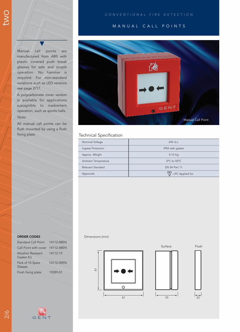
Manual Call Point
Dimensions (mm)
Manual call points aremanufactured from ABS withplastic covered push breakglasses for safe and simpleoperation. No hammer isrequired. For non-standardvariations such as LED versionssee page 2/17.
A polycarbonate cover versionis available for applicationssusceptible to inadvertentoperation, such as sports halls.
Note:
All manual call points can beflush mounted by using a flushfixing plate.
ORDER CODES
Standard Call Point 14112-08EN
Call Point with cover 14112-48EN
Weather Resistant 14112-19Gasket Kit
Pack of 10 Spare 14112-09ENGlasses
Flush fixing plate 19289-01
20
FlushSurface
5587
87

C O N V E N T I O N A L F I R E D E T E C T I O N
two
2/7
S M O K E D E T E C T O R S
Technical SpecificationType Ionisation Optical
Nominal Voltage 9 - 24V d.c. 9 - 24V d.c.
Quiescent Current 15µA 60µA
Ingress Protection IP30 IP30
Approx. Weight 0.11 Kg 0.11 Kg
Ambient Temperature -20ºC to +70ºC
Relevant Standards EN 54 Part 7
Approvals LPCB approved
104
73 w
ith b
ase
1046
17830-01 Ionisation Detector
Dimensions (mm)
The use of the diodebase, allows monitoringof a removed detectorto comply with BS 5839.N.B. Maximum of 20 perzone.
Smoke detectors for generalfire detection applications.
Ionisation smoke detectors aremore suited to fast burning,high energy fires whilst opticalsmoke detectors are suited forslow smouldering fires.
ABS casing with red LED fireindicator.
ORDER CODES
Ionisation 17830-01
Optical 17840-01
Common Base 17800-02
Common Base 17801-02 with Diode
Base less Diode 17800-01(surface cabling)
Base with Diode 17801-01(surface cabling)
Remote LED module 17899-01
Remote relay module 17888-44
S P E C I A L F E AT U R E
2/8
H E A T D E T E C T O R S
C O N V E N T I O N A L F I R E D E T E C T I O N
two
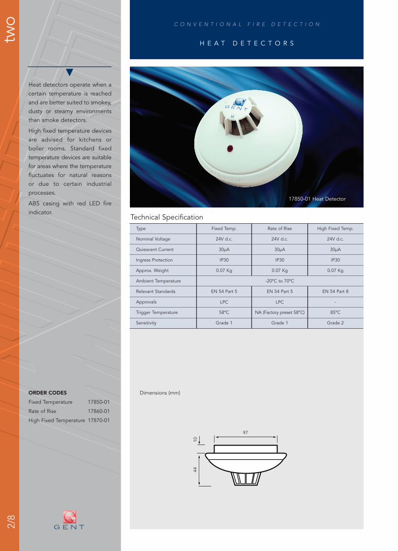
Heat detectors operate when acertain temperature is reachedand are better suited to smokey,dusty or steamy environmentsthan smoke detectors.
High fixed temperature devicesare advised for kitchens orboiler rooms. Standard fixedtemperature devices are suitablefor areas where the temperaturefluctuates for natural reasonsor due to certain industrialprocesses.
ABS casing with red LED fireindicator.
ORDER CODES
Fixed Temperature 17850-01
Rate of Rise 17860-01
High Fixed Temperature 17870-01
Technical SpecificationType Fixed Temp. Rate of Rise High Fixed Temp.
Nominal Voltage 24V d.c. 24V d.c. 24V d.c.
Quiescent Current 30µA 30µA 30µA
Ingress Protection IP30 IP30 IP30
Approx. Weight 0.07 Kg 0.07 Kg 0.07 Kg
Ambient Temperature -20ºC to 70ºC
Relevant Standards EN 54 Part 5 EN 54 Part 5 EN 54 Part 8
Approvals LPC LPC -
Trigger Temperature 58ºC NA (Factory preset 58°C) 85ºC
Sensitivity Grade 1 Grade 1 Grade 2
97
4410
17850-01 Heat Detector
Dimensions (mm)

2/9C O N V E N T I O N A L F I R E D E T E C T I O N
two
B E A M S M O K E D E T E C T O R S
Optical smoke beam detectorsare suitable for large openareas where installation ofsingle point detectors may bedifficult or uneconomical.
Sheet steel case in an ivoryfinish.
Adjustable brackets.
Note: An additional 24V d.c.power supply is required.
ORDER CODES
Beam Detector 07011-41
Technical SpecificationNominal Voltage 24V d.c.
Quiescent Current Receiver: - 8mA
Transmitter: - 5mA
Ingress Protection IP 50
Approx. Packaged Weight 3.2 Kg
Ambient Temperature -20ºC to 55ºC
Relevant Standards BS 5839 Part 5
Beam Length 10m - 100m
Mounting Height 2.7m - 25m
65
210
95
101
85
260
07011-41 Beam Detector
Dimensions (mm)

two
2/10
D U C T S M O K E D E T E C T O R
C O N V E N T I O N A L F I R E D E T E C T I O N
Technical SpecificationIngress Protection IP54
Ambient Temperature -10ºC to +60ºC
Approx. Weight Approx 700 g
Finish ABS plastic (Grey)
Air Velocity 1M/S to 20M/S
Quiescent Current 90µA
17815-01 Duct Detector
120300
Dimensions (mm)
110
The duct detector kit iscomprised of a conventionaldetector and duct detectorhousing.
The duct detector is mountedon the outside of the airduct with the Venturi tubeprotruding through a hole intothe duct. A sample of the airinside the duct is fed into thesmoke detector via the Venturitube and then returned to theduct through the Venturi tube.
When the smoke density in thesampled air reaches the triggerlevel of the smoke detector analarm will be signalled on thefire alarm control panel.
ORDER CODES
Duct Detector 17815-01
Venturi Tube, 2.8m 781458
Venturi Tube, 1.5m 781457
Venturi Tube, 0.6m 781456
Mounting Kit 781459For round and installedair ducts.
Remote Relay Module 17899-44

S 3 E L E C T R O N I C S O U N D E R S / S T R O B E S
C O N V E N T I O N A L F I R E D E T E C T I O N
two
2/11
� Very low power consumption means more sounders and strobes per circuit
� The strobe option is equivalent to a standard 3w xenon strobe and uses 1/20th of the power
� 32 sounder tones are available
� Voice enhanced sounders are available in the range
� 4 voice phrases and a bell sound are available as standard
� All sound and strobe signals are synchronised to better than +/- 30mS over 20 minutes
� Sounders are compatible with 12V and 24V systems
� A third wire option allows the selection of 2 alternative sounds. Ideal for class change applications
� Products incorporate innovative design features for which multiple patents arepending
Order Codes
IP31 Low Profile Sounders
C3-SN-ST-RR Sounder/Strobe RedC3-SN-ST-WR Sounder/Strobe WhiteC3-SN-R Sounder RedC3-SN-W Sounder White
IP65 Low Profile Sounders
C3IP-SN-ST-RR Sounder/Strobe RedC3IP-SN-ST-WR Sounder/Strobe WhiteC3IP-SN-R Sounder RedC3IP-SN-W Sounder White
IP65 Strobe only
C2IP-ST-RR Strobe Red Body/ Red Lens
Remote Control
S3-CONTROL HandiLink IR Remote Control
Technical Specification - 1.0 Sounders & StrobesType Sounder Sounder/Strobe Strobe Only
Sound Output at 1m See Tone Table See Tone Table N/A
Strobe Flash Rate See Tone Table See Tone Table Variable
Strobe Output N/A Equivalent to a 3w Equivalent to a 3wXenon Strobe Xenon Strobe
Average Current See Tone Table See Tone Table 6 mA
Synchronisation Sound & Strobe synchronisation better than ±30mS over20 minutes with all units powered from the same circuit
Operating Voltage 10.8V – 28.8V 10.8V – 28.8V 10.8V – 28.8VRange
Maximum Reverse 30V/20µA 30V/20µA 30V/20µAMonitoring Voltage
Ingress Protection IP65C with the Deep Base IP31C with the Shallow Base
Approx Weight 0.3Kg 0.3Kg 0.3Kg
Operating Temperature -10ºC to 50ºC -10ºC to 50ºC -10ºC to 50ºC
Relevant Standards EN54: Pt 3 EN54: Pt 3 N/A(Sounder only)
IR Control Operating 3m 3m N/ADistance
Approvals LPCB Applied for
The S-cubed range of alarmsounders incorporate sound,speech and strobe effects all inone range of alarm devices. Therange offers all variants in thechoice of 2 colours red or whitewith either a shallow baseversion sealed to IP31 or a deepbase version sealed to IP65.All the low profile soundershave the option of an integralstrobe.
As an aid to commissioningthere is the option to use theHandiLink IR remote control toselect sounder tones and adjustthe volume remotely. This meansphysical access is not requiredto make this adjustment. Thisfacility is only active when thesounders are turned on from thefire alarm panel.

S 3 E L E C T R O N I C S O U N D E R S / S T R O B E S
C O N V E N T I O N A L F I R E D E T E C T I O N
two
2/12
Signal 1 Strobe Description SW1 Graphical 12V With Without 24V With Without Signal 2 Strobe Signal 3 StrobeSwitch representation dBA @1m Strobe Strobe dBA @1m Strobe Strobe
mA mA mA mA mA
Tone 1 1Hz Alternating tone 800/ 970Hz @ 2Hz - FP 1063.1 101.8 16.5 7.4 101.8 9.5 3.4 Tone 3 0.5Hz Tone 6 1HzTelecoms BS 5839: Part 1
Tone 2 1Hz Alternating tone 800/ 970Hz @ 1Hz - 101.7 16.5 7.3 101.7 9.5 3.4 Tone 3 0.5Hz Tone 6 1HzBS 5839: Part 1
Tone 3 1Hz Intermittent tone 970Hz @ 1Hz LF back up alarm 101.6 15.5 4.5 101.6 8.2 2.0 Tone 5 0.8Hz Tone 6 1Hz- BS 5839: Part 1
Tone 4 1Hz Intermittent tone 2850Hz @ 1Hz HF back up 103.7 15.8 5.5 103.7 8.5 2.5 Tone 3 0.5Hz Tone 6 1Hzalarm - 2nd tone BS 5839: Part 1
Tone 5 0.8Hz Intermittent tone 970Hz 0.25s - on, 1s off - 101.2 12.0 2.0 101.4 6.0 1.0 Tone 2 0.5Hz Tone 6 1HzBS 5839: Part 1
Tone 6 1Hz Continuous @ 970Hz - BS 5839: Part 1 102.0 16.5 8.0 102.1 9.8 3.7 Tone 3 0.5Hz Tone 1 1Hz
Tone 7 0.5Hz Slow sweep 300Hz- 1200Hz over 2s - Vds2300 99.3 13.0 7.9 99.3 7.0 3.7 Tone 3 0.5Hz Tone 6 1HzSignal
Tone 8 1Hz Fast sweep 800Hz - 970Hz @ 7Hz - 93.5 16.3 8.2 93.7 9.4 3.7 Tone 3 0.5Hz Tone 6 1HzBS 5839: Part 1
Tone 9 1Hz Medium sweep 800Hz - 970Hz @ 1Hz - 94.1 16.5 8.7 94.3 9.5 4.0 Tone 3 0.5Hz Tone 6 1HzBS 5839: Part 1
Tone 10 1Hz Continuous @ 2850Hz 104.4 16.5 9.7 104.7 10.2 4.4 Tone 3 0.5Hz Tone 6 1Hz
Tone 11 1Hz Sweep 2400 - 2850Hz @ 7Hz 100.2 16.5 11.2 100.8 10.6 5.4 Tone 12 0.5Hz Tone 10 1Hz
Tone 12 1Hz Sweep 2400 - 2850Hz @ 1Hz 101.9 16.5 12.0 102.7 11.5 5.8 Tone 3 0.5Hz Tone 10 1Hz
Tone 13 0.86Hz Slow whoop 500Hz - 1200Hz over 3s 98.8 15.5 7.5 99.2 8.7 3.5 Tone 3 0.5Hz Tone 6 1Hzwith 0.5s off
Tone 14 1Hz Sweep 1200Hz @ 1200Hz - 500Hz @ 1Hz with 96.6 16.2 7.3 98.1 9.5 3.5 Tone 3 0.5Hz Tone 6 1Hz10ms silence - German DIN tone evacuate
Tone 15 1Hz Alternating tone 2400/ 2850Hz @ 2Hz 101.7 16.5 12.0 102.5 11.8 6.2 Tone 12 0.5Hz Tone 10 1Hz
Tone 16 1Hz Alternating tone 554Hz for 100mS then 440Hz 89.3 15.8 5.2 89.6 8.7 2.5 Tone 3 0.5Hz Tone 6 1Hzfor 400ms - French AFNOR tone
Tone 17 1Hz Alternating tone 440Hz / 554Hz @ 2Hz - Turn 90.1 15.8 5.7 90.3 8.9 2.8 Tone 19 0.5Hz Tone 18 1Hzout Sweden
Tone 18 1Hz Continuous 700Hz - All clear Sweden 95.9 16.2 7.0 96.3 9.8 3.3 Tone 1 0.5Hz Tone 3 1Hz
Tone 19 Intermittent tone 700Hz 6s On 12s Off - Pre- vital 95.9 6.1 4.0 96.3 5.0 2.3 Tone 17 0.5Hz Tone 18 1Hzmessage Sweden
Tone 20 1Hz Intermittent tone 1000Hz @ 1Hz - Local warning 100.6 15.5 5.8 101.0 8.5 2.7 Tone 17 0.5Hz Tone 25 1HzSweden
Tone 21 1Hz Rising 1s, constant 4s, fall 1s @ 1000Hz - 100.9 16.0 10.0 101.2 10.0 4.0 Tone 3 0.5Hz Tone 6 1HzIndustrial alarm Germany
Tone 22 Intermittent tone 700Hz 4s On , 4s Off - 101.4 8.7 5.7 101.9 6.4 3.0 Tone 19 Tone 6 1HzIndustrial alarm Germany
Tone 23 Sync. Emergency evacuation to ISO 8201 - ISO 8201 104.0 12.0 4.0 104.5 6.0 1.5 Tone 3 0.5Hz Tone 6 1Hzpulses Tone
Tone 24 1Hz Slow whoop 500Hz - 1000Hz over 4.5s - 99.6 16.0 7.2 100.2 9.5 3.4 Tone 3 0.5Hz Tone 6 1HzEvacuate Netherlands
Tone 25 1Hz Siren (ramp up from 500Hz - 1200Hz in 3s then 98.2 16.0 7.5 98.5 9.5 3.5 Tone 3 0.5Hz Tone 6 1Hzramp down 1200Hz - 500Hz in 3s)
Tone 26 1Hz Fast whoop 500Hz - 1000Hz @ 7Hz 95.8 15.8 7.0 96.0 8.7 3.3 Tone 24 0.5Hz Tone 25 1Hz
Tone 27 Sync. US temporal tone LF 100.6 12.0 3.0 100.6 5.5 1.0 Tone 3 0.5Hz Tone 6 1Hzpulses
Tone 28 Sync. US temporal tone HF 99.0 11.8 2.5 99.0 5.3 0.8 Tone 4 0.5Hz Tone 6 1Hzpulses
Tone 29 1Hz LF buzz 800Hz- 970Hz @ 50Hz 98.8 16.3 9.4 99.2 10.0 4.3 Tone 3 0.5Hz Tone 6 1Hz
Tone 30 1Hz Alternate 2500/ 3100 @ 2Hz - Security alarm 101.6 16.5 13.0 102.2 10.8 6.4 Tone 3 0.5Hz Tone 31 1Hz
Tone 31 1Hz Alternate 2500 / 3100 @ 4Hz 101.2 16.5 13.0 102.0 10.8 6.4 Tone 3 0.5Hz Tone 8 1Hz
Tone 32 1Hz Define during manufacture - default is a fast siren 98.8 16.0 7.5 99.2 9.5 3.5 Tone 3 0.5Hz Tone 6 1Hz
The current data in the table are for Red strobe only.Note also the nominal sound frequencies stated in the table are based on the resonance frequency of the transducer.
Tone Table for Sounder Only and Sounder/Strobe Variants
6 5 4 3 2 1ON
6 5 4 3 2 1ON
6 5 4 3 2 1ON
6 5 4 3 2 1ON
6 5 4 3 2 1ON
6 5 4 3 2 1ON
6 5 4 3 2 1ON
6 5 4 3 2 1ON
6 5 4 3 2 1ON
6 5 4 3 2 1ON
6 5 4 3 2 1ON
6 5 4 3 2 1ON
6 5 4 3 2 1ON
6 5 4 3 2 1ON
6 5 4 3 2 1ON
6 5 4 3 2 1ON
6 5 4 3 2 1ON
6 5 4 3 2 1ON
6 5 4 3 2 1ON
6 5 4 3 2 1ON
6 5 4 3 2 1ON
6 5 4 3 2 1ON
6 5 4 3 2 1ON
6 5 4 3 2 1ON
6 5 4 3 2 1ON
6 5 4 3 2 1ON
6 5 4 3 2 1ON
6 5 4 3 2 1ON
6 5 4 3 2 1ON
6 5 4 3 2 1ON
6 5 4 3 2 1ON
6 5 4 3 2 1ON
0.5Hz6s - On
12s - Off
1Hz6s - On
12s - Off
1Hz4s - On4s - Off

S 3 V O I C E E N H A N C E D S O U N D E R S
C O N V E N T I O N A L F I R E D E T E C T I O N
two
2/13
Technical Specification - 1.1 Voice Enhanced Sounders & StrobesType Voice Enhanced Sounder Voice Enhanced Sounder/ Strobe
Sound Output at 1m See Table 3 See Table 3
Strobe Flash Rate See Table 3 See Table 3
Strobe Output Equivalent to a 3w Xenon Strobe
Average Current See Table 3 See Table 3
Synchronisation Sound & Strobe synchronisation better than ± 30mS over 20 minuteswith all units powered from the same circuit
Message and Attention 10 Seconds 10 SecondsTone Period
Operating Voltage 10.8V – 28.8V 10.8V – 28.8VRange
Maximum Reverse 30V/20µA 30V/20µAMonitoring Voltage
Ingress Protection IP65C with the Deep Base IP31C with the Shallow Base
Approx Weight 0.3 Kg 0.3 Kg
Operating Temperature -10ºC to 50ºC -10ºC to 50ºC
IR Control Operating 3m 3mDistance
Table 1
Message No. Speech Message
M1 Attention please this is an emergency please leave the building by the nearest available exit. (female voice)
M2 An incident has been reported in this building please await further instructions. (female voice)
M3 This is a test message no action is required. (female voice)
M4 This is a fire alarm! please leave the building immediately by the nearest available exit. (male voice)
Complex Tone No. Description of Tone
Alarm Bell (equivalent to 8" Solenoid Bell)
CT0 12V 105dBA @ 1m with strobe 14.2mA (without strobe 4.5mA)
24V 105.5dBA @ 1m with strobe 12mA (without strobe 4.5mA)
Standard messages and complex tones (Voice IC 2202- 001)
Table 2
Tone Description Graphical representation
Tone 1 Alternating tone 800/ 970Hz @ 2Hz - FP 1063.1 Telecoms
Tone 2 Intermittent tone 970Hz @ 1Hz LF back up alarm - BS 5839: Part 1
Tone 3 Intermittent tone 970Hz 0.25s on, 1s off - BS 5839: Part 1
Tone 4 Continuous @ 970Hz - BS 5839: Part 1
Tone 5 Fast sweep 800Hz - 970Hz @ 7Hz - BS 5839: Part 1
Tone 6 Medium sweep 800Hz - 970Hz @ 1Hz - BS 5839: Part 1
Tone 7 Sweep 1200Hz @ 1200Hz - 500Hz @ 1Hz with 10ms silence - German DIN tone evacuate
Tone 8 Alternating tone 440Hz / 554Hz @ 2Hz - Turn out Sweden
Tone 9 Intermittent tone 1000Hz @ 1Hz - Local warning Sweden
Tone 10 Intermittent Tone 700Hz 4s On , 4s Off - Industrial alarm Germany
Tone 11 Fast whoop 500Hz - 1000Hz @ 7Hz
Tone 12 US temporal tone LF
Tone 13 US temporal tone HF
Tone 14 Define during manufacture - default is a fast siren
Note: The nominal sound frequencies stated in the table are based on the resonance frequencyof the transducer.
Conventional Speech Sounder and StrobeNote: Only the messages and complex tones specified in table 1 are applicable to this S-cubed product.
How to select a speech messageand attention tone
1. Select the required speechmessage and tone from thesignal 1 column of table 3referring to table 1 and 2 formessage and tone descriptions.
2. If the third wire option is usedthe two alternative messages andtones for your first selection areshown on the right hand side oftable 3.
3. After making a selection set theswitch SW1 as shown in the SW1column of table 3.
Order CodesIP31 Low Profile Sounders
C3-VO-R Voice Sounder RedC3-VO-W Voice Sounder WhiteC3-VO-ST-RR Voice Sounder/Strobe
RedC3-VO-ST-WR Voice Sounder/Strobe
White
IP65 Low Profile Sounders
C3IP-VO-R Voice Sounder RedC3IP-VO-W Voice Sounder WhiteC3IP-VO-ST-RR Voice Sounder/Strobe
RedC3IP-VO-ST-WR Voice Sounder/Strobe
White
Remote Control
S3-CONTROL HandiLink IR Remote Control

S 3 V O I C E E N H A N C E D S O U N D E R S
C O N V E N T I O N A L F I R E D E T E C T I O N
two
2/14
Signal 1 Strobe Attention SW1 12V With Strobe Without 24V With Without Signal 2 Strobe Attention Signal 3 Strobe AttentionMessage Tone Switch dBA @1m mA Strobe mA dBA @1m Strobe mA Strobe mA Message Tone Message Tone
M1 1Hz Tone 1 101.8 16.5 7.4 101.8 9.5 3.4 M2 0.5Hz Tone 2 M3 1Hz Tone 4
M1 1Hz Tone 6 94.1 16.5 8.7 94.3 9.5 4.0 M2 0.5Hz Tone 3 M3 1Hz Tone 4
M1 1Hz Tone 11 95.8 15.8 7.0 96.0 8.7 3.3 M2 0.5Hz Tone 9 M3 1Hz Tone 4
M1 1Hz Tone 5 93.5 16.3 8.2 93.7 9.4 3.7 M2 0.5Hz Tone 3 M3 1Hz Tone 4
M1 1Hz Tone 8 90.1 15.8 5.7 90.3 8.9 2.8 M2 0.5Hz Tone 9 M3 1Hz Tone 4
M1 1Hz Tone 7 96.6 16.2 7.3 98.1 9.5 3.5 M2 0.5Hz Tone 10 M3 1Hz Tone 4
M1 1Hz Tone 12 100.6 12.0 3.0 100.6 5.5 1.0 M2 0.5Hz Tone 13 M3 1Hz Tone 4
M1 1Hz Tone 14 98.8 16.0 7.5 99.2 9.5 3.5 M2 0.5Hz Tone 14 M3 1Hz Tone 14
M4 1Hz Tone 1 101.8 16.5 7.4 101.8 9.5 3.4 M5 0.5Hz Tone 2 M6 1Hz Tone 4
M4 1Hz Tone 6 94.1 16.5 8.7 94.3 9.5 4.0 M5 0.5Hz Tone 3 M6 1Hz Tone 4
M4 1Hz Tone 11 95.8 15.8 7.0 96.0 8.7 3.3 M5 0.5Hz Tone 9 M6 1Hz Tone 4
M4 1Hz Tone 5 93.5 16.3 8.2 93.7 9.4 3.7 M5 0.5Hz Tone 3 M6 1Hz Tone 4
M4 1Hz Tone 8 90.1 15.8 5.7 90.3 8.9 2.8 M5 0.5Hz Tone 9 M6 1Hz Tone 4
M4 1Hz Tone 7 96.6 16.2 7.3 98.1 9.5 3.5 M5 0.5Hz Tone 10 M6 1Hz Tone 4
M4 1Hz Tone 12 100.6 12.0 3.0 100.6 5.5 1.0 M5 0.5Hz Tone 13 M6 1Hz Tone 4
M4 1Hz Tone 14 98.8 16.0 7.5 99.2 9.5 3.5 M2 0.5Hz Tone 14 M3 1Hz Tone 14
Ml 1Hz CT0 M2 0.5Hz CT0~ M3 1Hz CT0
M1 1Hz CT1 M2 0.5Hz CT1~ M3 1Hz CT1
M1 1Hz CT2 M2 0.5Hz CT2~ M3 1Hz CT2
M1 1Hz CT3 M2 0.5Hz CT3~ M3 1Hz CT3
M1 1Hz CT4 M2 0.5Hz CT4~ M3 1Hz CT4
M1 1Hz CT5 M2 0.5Hz CT5~ M3 1Hz CT5
M1 1Hz CT6 M2 0.5Hz CT6~ M3 1Hz CT6
M1 1Hz CT7 M2 0.5Hz CT7~ M3 1Hz CT7
- 1Hz CT0 - 0.5Hz CT0~ - 1Hz CT0
- 1Hz CT1 - 0.5Hz CT1~ - 1Hz CT1
- 1Hz CT2 - 0.5Hz CT2~ - 1Hz CT2
- 1Hz CT3 - 0.5Hz CT3~ - 1Hz CT3
- 1Hz CT4 - 0.5Hz CT4~ - 1Hz CT4
- 1Hz CT5 - 0.5Hz CT5~ - 1Hz CT5
- 1Hz CT6 - 0.5Hz CT6~ - 1Hz CT6
- 1Hz CT7 - 0.5Hz CT7~ - 1Hz CT7
Tone
onl
y
Decibel (dBA) and current (mA) values Intermittent 1S On and 1S Off
6 5 4 3 2 1ON
6 5 4 3 2 1ON
6 5 4 3 2 1ON
6 5 4 3 2 1ON
6 5 4 3 2 1ON
6 5 4 3 2 1ON
6 5 4 3 2 1ON
6 5 4 3 2 1ON
6 5 4 3 2 1ON
6 5 4 3 2 1ON
6 5 4 3 2 1ON
6 5 4 3 2 1ON
6 5 4 3 2 1ON
6 5 4 3 2 1ON
6 5 4 3 2 1ON
6 5 4 3 2 1ON
6 5 4 3 2 1ON
6 5 4 3 2 1ON
6 5 4 3 2 1ON
6 5 4 3 2 1ON
6 5 4 3 2 1ON
6 5 4 3 2 1ON
6 5 4 3 2 1ON
6 5 4 3 2 1ON
6 5 4 3 2 1ON
6 5 4 3 2 1ON
6 5 4 3 2 1ON
6 5 4 3 2 1ON
6 5 4 3 2 1ON
6 5 4 3 2 1ON
6 5 4 3 2 1ON
6 5 4 3 2 1ON
Refer to decibel (dBA) and current (mA) values
stated in table 1.
Note: Only the complex tones (CTn) and speech
messages (Mn) specified in table 1 are valid.
The highlighted row in this table show the factory
default setting of the S-cubed unit.
Att
enti
on
tone
fo
llow
ed b
y sp
eech
mes
sag
eTable 3 - Tone/Voice table for Voice and Voice/Strobe Variants

two
2/15
B E L L S
C O N V E N T I O N A L F I R E D E T E C T I O N
Technical SpecificationType 24V d.c. 230V a.c.
Ingress Protection Standard IP40 Standard IP41
Special IP55 Special IP55
Approx. Weight 1.1 Kg 1.25 Kg
Ambient Temperature Indoor, -10ºC to 55ºC
Sound Output at 1m 93dBA 96dBA
Current at Nominal Voltage 30mA 30mA
Relevant Standard EN 54 Part 3
155 85
155
130
12141-04 Bell
Dimensions (mm)
An electric bell for a widerange of uses.
Metal casing available in red orgrey finish.
Suitable for semi flush orsurface mounting.
ORDER CODES
24V d.c. Bell, Red 12141-04
24V d.c. Bell, Red, IP55 12143-04
230V a.c. Bell, Red 12142-09
230V a.c. Bell, Red, IP55 12144-09
24V d.c. Bell, Grey 12141-54
230V a.c Bell, Grey 12142-59
230V a.c Bell, Grey IP55 12144-59
Gent bell installed at the DjangologyArts Centre, Nottingham.

C O N V E N T I O N A L F I R E D E T E C T I O N
two
2/16
E L E C T R O N I C S O U N D E R
93Shallow Base
Sounder BaseBedhead Sounder
Deep Base
30
42
Technical SpecificationType Shallow Base Deep Base Bedhead Sounder Base
IP Rating IP54 IP65 IP54 IP54
Approximate Weight 0.24kg 0.26kg 0.11kg 0.15kg
Operation Continuous Continuous Continuous Continuous
Operating Voltage Range 9 - 28V d.c. 9 - 28V d.c. 9 - 28V d.c. 9 - 28V d.c.
Typical Sound Output 93dBA 93dBA 94dBA 87dBA@ 1m, 12V d.c.
Typical Sound Output 100dBA 100dBA 97dBA 93dBA@ 1m, 24V d.c.
Current Consumption 8mA @ 12V, 18mA @24V
IP Rating IP54 IP65 IP54 IP54
Approximate Weight 0.29kg 0.31kg 0.11kg 0.15kg
Ambient Temperature -25ºC to +80ºC -40ºC to +80ºC
Finish ABS plastic
74451-24NM Shallow Base Sounder
Dimensions (mm)
73
86112
105
‘Squashni’ sounders areuseful for small rooms suchas Halls of Residences.They may be used with adetector which reduces thenumber of fixing points oras a standalone sounderwith a cover plate.
S P E C I A L F E AT U R E
A versatile 24V electronicsounder for use in a widerange of applications.
Sound signals may be set in 3ways; continuous, intermittentor warble.
ORDER CODES
Shallow Base (Red) 74451-24NM
Deep Base 74452-24NM(IP65 Red)
Bedhead Sounder 02519-52(White)
Sounder Base 02601-31
Shallow Base 74451-55NM(White)
Deep Base 74452-55NM(IP65 White)
SOUNDER BASE
DETECTOR BASE
DETECTOR

two
2/17
S I R E N
C O N V E N T I O N A L F I R E D E T E C T I O N
Technical SpecificationType 230V a.c. 230V a.c. Weatherproof 24Vdc Siren
Ingress Protection IP44 IP65 IP44
Approx. Weight 0.5 Kg 1.7 Kg 0.21 Kg
Sound Output at 1m 100dBA 120dBA 103dBA
Current Consumption 85mA 460mA 500mA
Output Frequency 1000Hz 1800Hz 1000Hz
Ambient Temperature Indoor, -30ºC to 80ºC Indoor/Outdoor, -30ºC to 80ºC Indoor -30ºC to 80ºC
Relevant Standard EN 54 Part 3
Rating Continuous
Finish High impact ABS (RAL 9002 grey) Grey stove enamel High Impact ABS (RAL 9002 grey)
130
70
89
195
84 92
133
LOW VOLTAGE MODEL MAINS VOLTAGE MODEL
WEATHERPROOF VERSION
02702-01 Siren
Dimensions (mm)
A range of electric motordriven sirens which areparticularly well suited fornoisy industrial environments.
A weatherproof version isavailable for outdoor use.
ORDER CODES
230V a.c. Siren 02702-01
230V a.c. Siren 02701-01Weatherproof
24V d.c. Siren 02703-01
D O O R R E L E A S E
C O N V E N T I O N A L F I R E D E T E C T I O N
two
2/18
Technical SpecificationType 24V d.c. 230V a.c.
Approx. Weight Door plate, 0.07 Kg Door holder, 0.53 Kg
Current Consumption 22mA 17.5mA
Ambient Temperature Indoor/Outdoor, -10º to + 50ºC
Nominal Magnetic Pull 11 Kgf
Relevent Standard BS 5839: Part 3
Finish Moulded ABS
23
96 45
96 72 d
ia
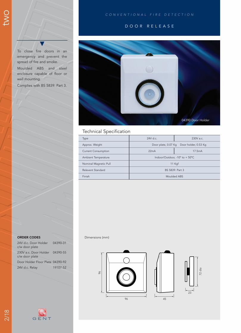
04390 Door Holder
Dimensions (mm)
To close fire doors in anemergency and prevent thespread of fire and smoke.
Moulded ABS and steelenclosure capable of floor orwall mounting.
Complies with BS 5839: Part 3.
ORDER CODES
24V d.c. Door Holder 04390-31c/w door plate
230V a.c. Door Holder 04390-55c/w door plate
Door Holder Floor Plate 04390-92
24V d.c. Relay 19107-52

C O N V E N T I O N A L F I R E D E T E C T I O N
two
2/19
R E L A Y S
Technical SpecificationCoil Voltage 24V d.c. (mini) 12V d.c. 24V d.c. 230V a.c.
Coil Current 22mA 100mA 50mA 30mA
Contact Rating 240V a.c. 2A 6A 6A 6A
Contact Rating 24V d.c 3A 5A 5A 5A
Profile Low High High High
Max. Capacity 4 mini relays 2 base or relay/mini mixture
Ambient Temperature Indoor/Outdoor, 0 - 40ºC, IP67
75125
50
125
25
19100-12 Low Profile Enclosure
Dimensions (mm)
Low profile enclosure to housemini relays for light loads ordeep enclosure for heavy dutyapplications involving relaysand timers.
All purpose polycarbonateconstruction.
Suitable for activating classchange or ‘start work’ signals.
ORDER CODES
24V d.c. Relay 19107-52c/w enclosure
High Profile Enclosure 19100-02
Low Profile Enclosure 19100-12
24V d.c. Mini Relay 19102-52
24V d.c. Relay 19104-52
230V a.c. Relay 19104-55
24V d.c. Timer 19106-02
24V d.c. Pulsar 19106-03
12V d.c. Relay 19104-30

2/20
To supply additional standbypower for control panels orrelays.
Protected against over-voltageand reverse polarity connections.
Fault monitoring to complywith BS 5839.
ORDER CODESPower Supply Units (less cells)
24V, 1.25A charger 05211-24Continuous rating 0.625A
24V, 4.0A charger 05214-24Continuous rating 2.0A
24V, 6.0A charger 05216-24
C O N V E N T I O N A L F I R E D E T E C T I O N
two
P O W E R S U P P L I E S
Technical SpecificationMains Input 230V a.c. 230V a.c.
Output Current 6A 4A 1.25A
Output Voltage 27.5V d.c. 27.6V d.c.
Operating Temperature -10º to +40ºC -10º to +50ºC
Max. Battery Capacity 2 x 12V/24Ah 2 x 12V/12Ah 2 x 12V/7Ah
Approx. Weight 8.5 Kg 12Kg 7.5Kg
408 190
380
05216-24 Power Supply Unit
Dimensions (mm)
C O N V E N T I O N A L F I R E D E T E C T I O N
two
2/21
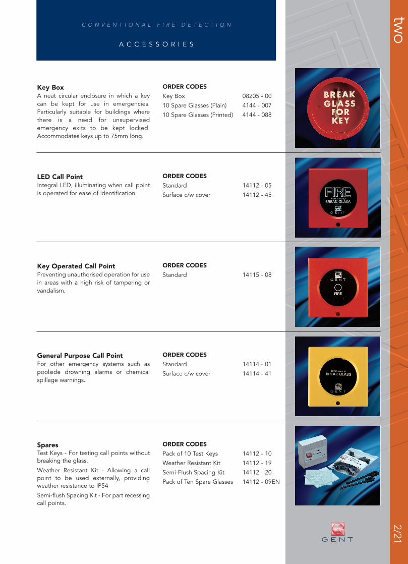
Key BoxA neat circular enclosure in which a keycan be kept for use in emergencies.Particularly suitable for buildings wherethere is a need for unsupervisedemergency exits to be kept locked.Accommodates keys up to 75mm long.
A C C E S S O R I E S
ORDER CODES
Key Box 08205 - 00
10 Spare Glasses (Plain) 4144 - 007
10 Spare Glasses (Printed) 4144 - 088
LED Call PointIntegral LED, illuminating when call pointis operated for ease of identification.
ORDER CODES
Standard 14112 - 05
Surface c/w cover 14112 - 45
Key Operated Call PointPreventing unauthorised operation for usein areas with a high risk of tampering orvandalism.
ORDER CODES
Standard 14115 - 08
General Purpose Call PointFor other emergency systems such aspoolside drowning alarms or chemicalspillage warnings.
ORDER CODES
Standard 14114 - 01
Surface c/w cover 14114 - 41
SparesTest Keys - For testing call points withoutbreaking the glass.
Weather Resistant Kit - Allowing a callpoint to be used externally, providingweather resistance to IP54
Semi-flush Spacing Kit - For part recessingcall points.
ORDER CODES
Pack of 10 Test Keys 14112 - 10
Weather Resistant Kit 14112 - 19
Semi-Flush Spacing Kit 14112 - 20
Pack of Ten Spare Glasses 14112 - 09EN

2/22
C O N V E N T I O N A L F I R E D E T E C T I O N
two
M A X I M U M S Y S T E M L O A D I N G
No. Quiescent Total LoadLoad (µA) (µA)
(a) (b) (a x b)
Ionisation Smoke Detector 15
Optical Smoke Detector 60
Fixed Temperature Heat Detector 30
Rate of Rise Heat Detector 30
High Temperature Heat Detector 30
24V d.c. Duct Detector 90
Grand Total
Zone Loading
Notes:1. If detector removal monitoring is
required to comply with BS 5839, adetector base with diode should beused and the maximum number ofdetectors should not exceed 20 perzone.
To calculate the maximum zone loading complete the table below and ensure that thegrand total does not exceed system limits (see pages 2/3 - 2/4).
To calculate the maximum sounder loading complete the table below and ensure that thegrand total does not exceed system limits (see pages 2/4 - 2/5).
Note:1. Sirens will require a separate power
supply.
2. Xenon flashers may require a separatepower supply.
No. Quiescent Total Load(mA) (mA)
(a) (b) (a x b)
24V d.c. Electronic Sounder 18
Sounder Base 18
24V d.c. Bell 30
S3 Sounder Strobe *24V d.c. Xenon (Low current) 45
*See tone table for specific quiescent currents. Grand Total
Sounder Circuit Loading
2. Any number of manual call points maybe included in zone calculations.
3. Beam detectors will require a separatepower supply.

2/23C O N V E N T I O N A L F I R E D E T E C T I O N
two
N O T E S