
XD3200 - Mitsubishi Electric This User Manual is important to you. Please read it before using your...
53
XD3200 This User Manual is important to you. Please read it before using your projector. DLP™ PROJECTOR MODEL XD3200U User Manual
Transcript of XD3200 - Mitsubishi Electric This User Manual is important to you. Please read it before using your...

XD3200This User Manual is important to you.Please read it before using your projector.
DLP™ PROJECTORMODEL
XD3200UUser Manual
EN-2
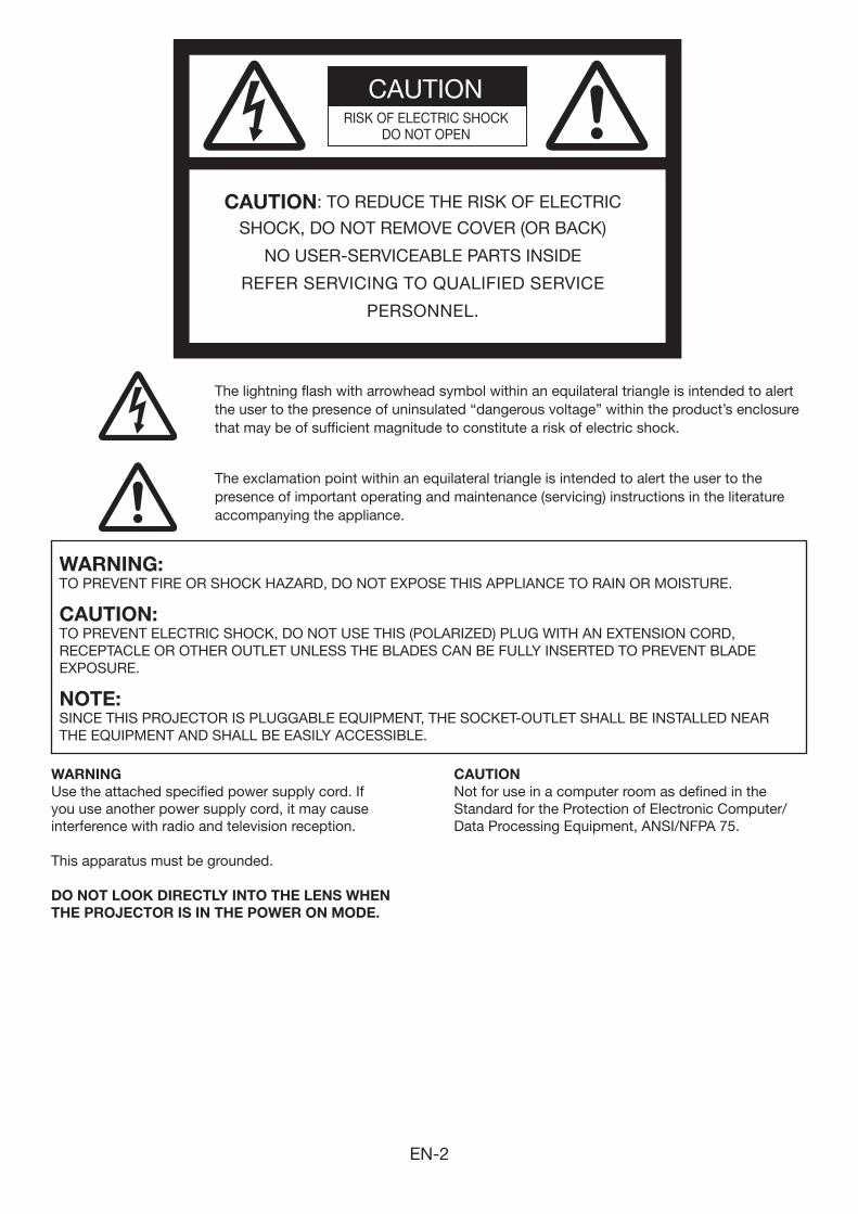
CAUTIONRISK OF ELECTRIC SHOCK
DO NOT OPEN
CAUTION: TO REDUCE THE RISK OF ELECTRIC
SHOCK, DO NOT REMOVE COVER (OR BACK)
NO USER-SERVICEABLE PARTS INSIDE
REFER SERVICING TO QUALIFIED SERVICE
PERSONNEL.
The lightning flash with arrowhead symbol within an equilateral triangle is intended to alert the user to the presence of uninsulated “dangerous voltage” within the product’s enclosure that may be of sufficient magnitude to constitute a risk of electric shock.
The exclamation point within an equilateral triangle is intended to alert the user to the presence of important operating and maintenance (servicing) instructions in the literature accompanying the appliance.
WARNING:TO PREVENT FIRE OR SHOCK HAZARD, DO NOT EXPOSE THIS APPLIANCE TO RAIN OR MOISTURE.
CAUTION:TO PREVENT ELECTRIC SHOCK, DO NOT USE THIS (POLARIZED) PLUG WITH AN EXTENSION CORD, RECEPTACLE OR OTHER OUTLET UNLESS THE BLADES CAN BE FULLY INSERTED TO PREVENT BLADE EXPOSURE.
NOTE:SINCE THIS PROJECTOR IS PLUGGABLE EQUIPMENT, THE SOCKET-OUTLET SHALL BE INSTALLED NEAR THE EQUIPMENT AND SHALL BE EASILY ACCESSIBLE.
WARNINGUse the attached specified power supply cord. If you use another power supply cord, it may cause interference with radio and television reception.
This apparatus must be grounded.
DO NOT LOOK DIRECTLY INTO THE LENS WHEN THE PROJECTOR IS IN THE POWER ON MODE.
CAUTIONNot for use in a computer room as defined in the Standard for the Protection of Electronic Computer/Data Processing Equipment, ANSI/NFPA 75.
EN-3
ContentsImportant safeguards ........................................................................................................................4Preparing your projector ....................................................................................................................6Using the remote control ...................................................................................................................9Setting up your projector .................................................................................................................10Viewing computer images ...............................................................................................................13Viewing video images ......................................................................................................................19Menu operation ...............................................................................................................................25Adjusting projected images .............................................................................................................33Advanced features ..........................................................................................................................37Indicators .........................................................................................................................................42Replacing the lamp .........................................................................................................................43Maintenance ....................................................................................................................................45Troubleshooting ...............................................................................................................................46Specifications ..................................................................................................................................50
Trademark, Registered trademark• DLP™,DigitalMicromirrorDevice,DMDandBrilliantColor™arealltrademarksofTexasInstruments.• HDMI,theHDMIlogoandHigh-DefinitionMultimediaInterfacearetrademarksorregisteredtrademarksofHDMI
Licensing LLC.• ThetrademarkofPJLinkistrademarkappliedforregistrationorregisteredtrademarkinJapan,theUnitedStates,
and other countries and areas.• Otherbrandorproductnamesaretrademarksorregisteredtrademarksoftheirrespectiveholders.
EN-4
Important safeguardsPlease read all these instructions regarding your projector and retain them for future reference. Follow all warnings and instructions marked on the projector.
1. Read instructions All the safety and operating instructions should be
read before the appliance is operated.
2. Retain instructions The safety and operating instructions should be
retained for future reference.
3. Warnings All warnings on the appliance and in the operating
instructions should be adhered to.
4. Instructions All operating instructions must be followed.
5. Cleaning Unplug this projector from the wall outlet before
cleaning it. Do not use liquid aerosol cleaners. Use a damp soft cloth for cleaning.
6. Attachments and equipment Never add any attachments and/or equipment
without the approval of the manufacturer as such additions may result in the risk of fire, electric shock or other personal injury.
7. Water and moisture Do not use this projector near water or in contact
with water.
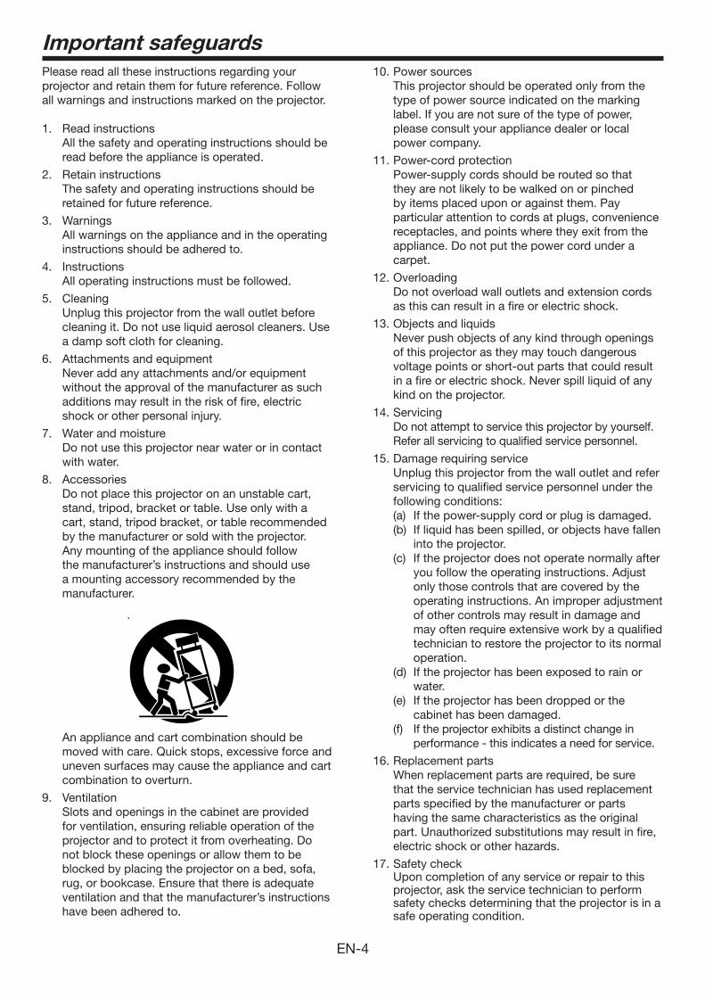
8. Accessories Do not place this projector on an unstable cart,
stand, tripod, bracket or table. Use only with a cart, stand, tripod bracket, or table recommended by the manufacturer or sold with the projector. Any mounting of the appliance should follow the manufacturer’s instructions and should use a mounting accessory recommended by the manufacturer.
10. Power sources This projector should be operated only from the
type of power source indicated on the marking label. If you are not sure of the type of power, please consult your appliance dealer or local power company.
11. Power-cord protection Power-supply cords should be routed so that
they are not likely to be walked on or pinched by items placed upon or against them. Pay particular attention to cords at plugs, convenience receptacles, and points where they exit from the appliance. Do not put the power cord under a carpet.
12. Overloading Do not overload wall outlets and extension cords
as this can result in a fire or electric shock.
13. Objects and liquids Never push objects of any kind through openings
of this projector as they may touch dangerous voltage points or short-out parts that could result in a fire or electric shock. Never spill liquid of any kind on the projector.
14. Servicing Do not attempt to service this projector by yourself.
Refer all servicing to qualified service personnel.
15. Damage requiring service Unplug this projector from the wall outlet and refer
servicing to qualified service personnel under the following conditions:(a) If the power-supply cord or plug is damaged.(b) If liquid has been spilled, or objects have fallen
into the projector.(c) If the projector does not operate normally after
you follow the operating instructions. Adjust only those controls that are covered by the operating instructions. An improper adjustment of other controls may result in damage and may often require extensive work by a qualified technician to restore the projector to its normal operation.
(d) If the projector has been exposed to rain or water.
(e) If the projector has been dropped or the cabinet has been damaged.
(f) If the projector exhibits a distinct change in performance - this indicates a need for service.
16. Replacement parts When replacement parts are required, be sure
that the service technician has used replacement parts specified by the manufacturer or parts having the same characteristics as the original part. Unauthorized substitutions may result in fire, electric shock or other hazards.
17. Safety check Upon completion of any service or repair to this
projector, ask the service technician to perform safety checks determining that the projector is in a safe operating condition.
An appliance and cart combination should be moved with care. Quick stops, excessive force and uneven surfaces may cause the appliance and cart combination to overturn.
9. Ventilation Slots and openings in the cabinet are provided
for ventilation, ensuring reliable operation of the projector and to protect it from overheating. Do not block these openings or allow them to be blocked by placing the projector on a bed, sofa, rug, or bookcase. Ensure that there is adequate ventilation and that the manufacturer’s instructions have been adhered to.
EN-5
Important safeguards (continued)
WARNING:Unplug immediately if there is something wrong with your projector.Do not operate if smoke, strange noise or odor comes out of your projector. It might cause fire or electric shock. In this case, unplug immediately and contact your dealer.
Never remove the cabinet.This projector contains high voltage circuitry. An inadvertent contact may result in an electric shock. Except as specifically explained in the User Manual do not attempt to service this product by yourself. Please contact your dealer when you want to fix, adjust or inspect the projector.
Do not modify this equipment.It can lead to fire or electric shock.
Do not keep using the damaged projector.If the projector is dropped and the cabinet is damaged, unplug the projector and contact your dealer for inspection. It may lead to fire if you keep using the damaged projector.
Do not face the projector lens to the sun.It can lead to fire.
Use correct voltage.If you use incorrect voltage, it can lead to fire.
Do not place the projector on uneven surface. Place the projection on a leveled and stable surface only. Please do not place equipment on unstable surfaces.
Do not look into the lens when it is operating.It may hurt your eyes. Never let children look into the lens when it is on.
Do not touch the air outlet grille and bottom plate, which become hot.Do not touch them or put other equipment in front of the air outlet grille. The air outlet grille and bottom plate, when heated, may cause injury or damage to other equipment. Also, do not set the projector on the desk which is easily affected by heat.
Do not look into the air outlet grille when projector is operating.Heat, dust, etc. may blow out of it and hurt your eyes.
Do not insert your fingers in the space between the lens and the cabinet. The lens may shift causing injury or damage to the projector.
Do not block the air inlet and outlet grilles.If they are blocked, heat may be generated inside the projector, causing deterioration in the projector quality and fire.
Do not use flammable solvents (benzene, thinner, etc.) and flammable aerosols near the projector.Flammable substances may ignite causing fire or breakdown because the temperature inside the projector rises very high while the lamp is illuminating.
Do not use the projector with condensation on it. It can lead to breakdown or other failure.
Place of installationFor safety’s sake, refrain from setting the projector at any place subjected to high temperature and high humidity. Please maintain an operating temperature, humidity, and altitude as specified below.• Operatingtemperature:between+41°F(+5°C)and
+95°F(+35°C)• Operatinghumidity:between30%and90%• Neverputanyheat-producingdeviceunderthe
projector so that the projector does not overheat.• Donotattachtheprojectortoaplacethatis
unstable or subjected to vibration.• Donotinstalltheprojectornearanyequipmentthat
produces a strong magnetic field. Also refrain from installing near the projector any cable carrying a large current.
• Placetheprojectoronasolid,vibrationfreesurface; otherwise it may fall, causing serious injury to a child or adult, and serious damage to the product.
• Donotstandtheprojector;itmayfall,causingserious injury and damage to the projector.
• Slantingtheprojectormorethan±10°(rightandleft)or±15°(frontandrear)maycausetroubleorexplosion of the lamp.
• Donotplacetheprojectornearair-conditioningunit, heater, or humidifier to avoid hot or moist air to the exhaust and ventilation hole of the projector.
EN-6
Preparing your projector
1
2
3
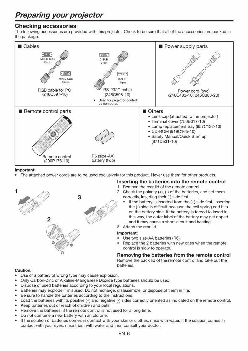
Checking accessoriesThe following accessories are provided with this projector. Check to be sure that all of the accessories are packed in the package.
Cables
Remote control parts
Remote control(290P176-10)
RS-232C cable(246C598-10)
R6 (size-AA) battery (two)
RGB cable for PC (246C597-10)
Others• Lens cap (attached to the projector)• Terminal cover (750B017-10)• Lamp replacement tray (857C132-10)• CD-ROM (919C165-10)• Safety Manual/Quick Start up
(871D531-10)
Mini D-SUB15-pin
Mini D-SUB15-pin
D-SUB 9-pin
Power supply parts
Power cord (two)(246C483-10, 246C383-20)
• Used for projector control by computer.
D-SUB 9-pin
Important:• Theattachedpowercordsaretobeusedexclusivelyforthisproduct.Neverusethemforotherproducts.
Inserting the batteries into the remote control1. Remove the rear lid of the remote control.2. Checkthepolarity(+),(-)ofthebatteries,andsetthem
correctly, inserting their (-) side first.• Ifthebatteryisinsertedfromthe(+)sidefirst,inserting
the (-) side is difficult because the coil spring end hits on the battery side. If the battery is forced to insert in this way, the outer label of the battery may get ripped and it may cause a short-circuit and heating.
3. Attach the rear lid.
Important:• Usetwosize-AAbatteries(R6).• Replacethe2batterieswithnewoneswhentheremote
control is slow to operate.
Removing the batteries from the remote controlRemove the back lid of the remote control and take out the batteries.
Caution: • Useofabatteryofwrongtypemaycauseexplosion.• OnlyCarbon-ZincorAlkaline-ManganeseDioxidetypebatteriesshouldbeused.• Disposeofusedbatteriesaccordingtoyourlocalregulations.• Batteriesmayexplodeifmisused.Donotrecharge,disassemble,ordisposeoftheminfire.• Besuretohandlethebatteriesaccordingtotheinstructions.• Loadthebatterieswithitspositive(+)andnegative(-)sidescorrectlyorientedasindicatedontheremotecontrol.• Keepbatteriesoutofreachofchildrenandpets.• Removethebatteries,iftheremotecontrolisnotusedforalongtime.• Donotcombineanewbatterywithanoldone.• Ifthesolutionofbatteriescomesincontactwithyourskinorclothes,rinsewithwater.Ifthesolutioncomesin
contact with your eyes, rinse them with water and then consult your doctor.
EN-7
Overview
5 63 94 10
1 2 7 8
54
7
10
6
9
11
8
1
2
3
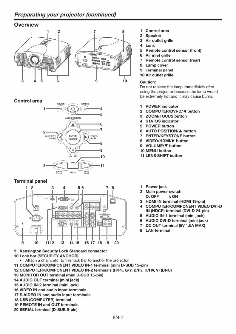
1 Control area2 Speaker3 Air outlet grille4 Lens5 Remote control sensor (front)6 Air inlet grille7 Remote control sensor (rear)8 Lamp cover9 Terminal panel10 Air outlet grille
Caution:Do not replace the lamp immediately after using the projector because the lamp would be extremely hot and it may cause burns.
Control area1 POWER indicator2 COMPUTER/DVI-D/ button3 ZOOM/FOCUS button4 STATUS indicator5 POWER button6 AUTO POSITION/ button7 ENTER/KEYSTONE button8 VIDEO/HDMI/ button9 VOLUME/ button10 MENU button11 LENS SHIFT button
1 2 3 4 6
16
75 8
1112 13 14 15 18 19 20109 17
1 Power jack2 Main power switch O: OFF I: ON3 HDMI IN terminal (HDMI 19-pin)4 COMPUTER/COMPONENT VIDEO DVI-D
IN (HDCP) terminal (DVI-D 24-pin)5 AUDIO IN-1 terminal (mini jack)6 AUDIO DVI-D terminal (mini jack)7 DC OUT terminal (5V 1.5A MAX)8 LAN terminal
Terminal panel
Preparating your projector (continued)
9 Kensington Security Lock Standard connector10 Lock bar (SECURITY ANCHOR)
• Attachachain,etc.tothislockbartoanchortheprojector.11 COMPUTER/COMPONENT VIDEO IN-1 terminal (mini D-SUB 15-pin)12 COMPUTER/COMPONENT VIDEO IN-2 terminals (R/PR, G/Y, B/PB, H/HV, V) (BNC)13 MONITOR OUT terminal (mini D-SUB 15-pin)14 AUDIO OUT terminal (mini jack)15 AUDIO IN-2 terminal (mini jack)16 VIDEO IN and audio input terminals17 S-VIDEO IN and audio input terminals18 USB (COMPUTER) terminal 19 REMOTE IN and OUT terminals20 SERIAL terminal (D-SUB 9-pin)
EN-8
1
Preparating your projector (continued)
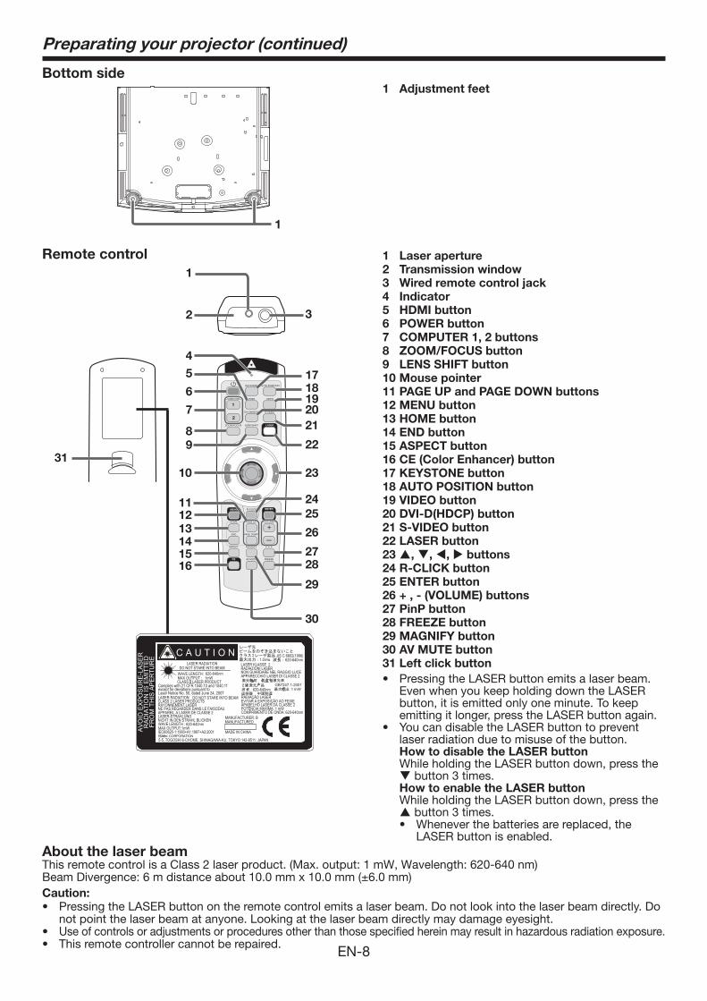
Bottom side1 Adjustment feet
31
COMPUTER HDMI VIDEO
KEYSTONE AUTO POSITION
DVI-D(HDCP) S-VIDEO
FREEZE
MAGNIFY
AV MUTE
PAGE UPHOME
PAGE DOWNEND
1
2
P in P
VOLUME
4
7
8
10
111213
1819
22
23
2425
26
2728
6
9
1415
5 17
16
29
30
CE
ASPECT
MENU ENTER
ZOOM/FOCUS LENS SHIFT LASER 2120
R-CLICK
1
2 3
Remote control 1 Laser aperture2 Transmission window3 Wired remote control jack4 Indicator5 HDMI button6 POWER button7 COMPUTER 1, 2 buttons8 ZOOM/FOCUS button9 LENS SHIFT button10 Mouse pointer11 PAGE UP and PAGE DOWN buttons12 MENU button13 HOME button14 END button15 ASPECT button16 CE (Color Enhancer) button17 KEYSTONE button18 AUTO POSITION button19 VIDEO button20 DVI-D(HDCP) button21 S-VIDEO button22 LASER button23 , , , buttons24 R-CLICK button25 ENTER button26 + , - (VOLUME) buttons27 PinP button28 FREEZE button29 MAGNIFY button30 AV MUTE button31 Left click button• PressingtheLASERbuttonemitsalaserbeam.
Even when you keep holding down the LASER button, it is emitted only one minute. To keep emitting it longer, press the LASER button again.
• YoucandisabletheLASERbuttontopreventlaser radiation due to misuse of the button.
How to disable the LASER button While holding the LASER button down, press the button 3 times.
How to enable the LASER button While holding the LASER button down, press the button 3 times.• Wheneverthebatteriesarereplaced,the
LASER button is enabled.About the laser beamThis remote control is a Class 2 laser product. (Max. output: 1 mW, Wavelength: 620-640 nm)BeamDivergence:6mdistanceabout10.0mmx10.0mm(±6.0mm)Caution:• Pressing the LASER button on the remote control emits a laser beam. Do not look into the laser beam directly. Do
not point the laser beam at anyone. Looking at the laser beam directly may damage eyesight. • Use of controls or adjustments or procedures other than those specified herein may result in hazardous radiation exposure.• This remote controller cannot be repaired.
EN-9
Using the remote control
30°30° 30°30°
20°
10°
20°
10°
20°
20°
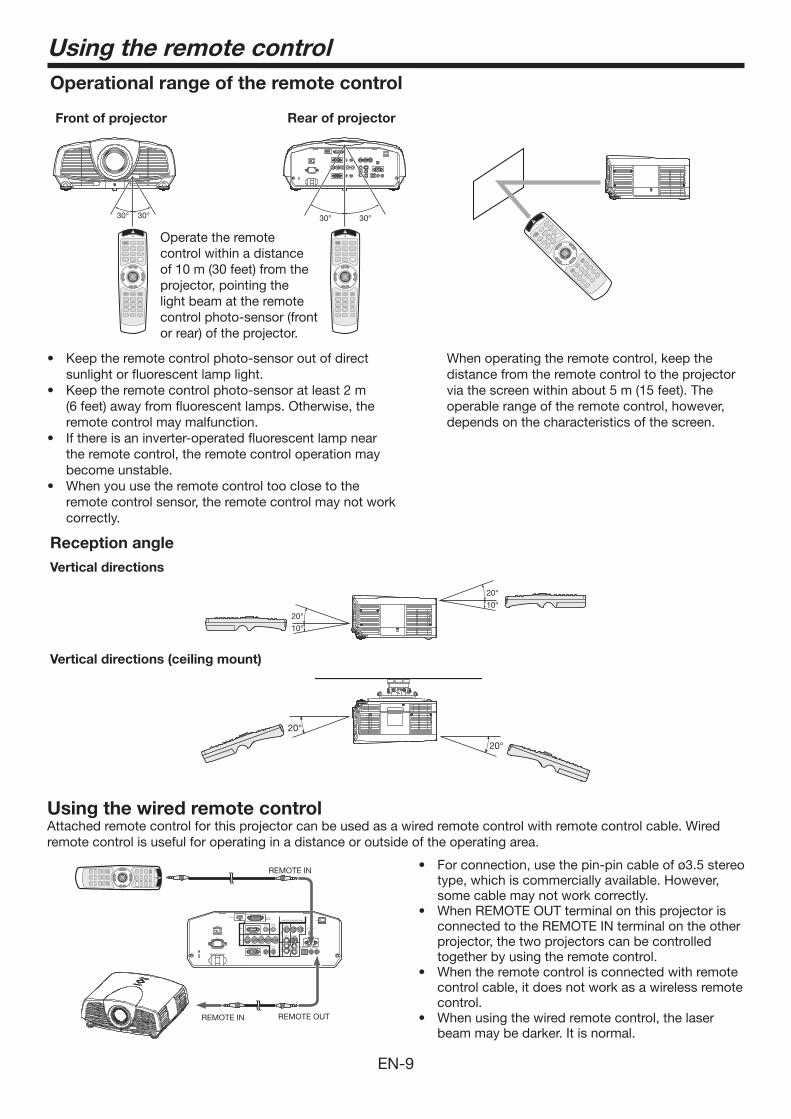
Operational range of the remote control
• Keeptheremotecontrolphoto-sensoroutofdirectsunlight or fluorescent lamp light.
• Keeptheremotecontrolphoto-sensoratleast2m(6 feet) away from fluorescent lamps. Otherwise, the remote control may malfunction.
• Ifthereisaninverter-operatedfluorescentlampnearthe remote control, the remote control operation may become unstable.
• Whenyouusetheremotecontroltooclosetotheremote control sensor, the remote control may not work correctly.
Reception angleVertical directions
Vertical directions (ceiling mount)
Front of projector Rear of projector
Operate the remote control within a distance of 10 m (30 feet) from the projector, pointing the light beam at the remote control photo-sensor (front or rear) of the projector.
When operating the remote control, keep the distance from the remote control to the projector via the screen within about 5 m (15 feet). The operable range of the remote control, however, depends on the characteristics of the screen.
Using the wired remote controlAttached remote control for this projector can be used as a wired remote control with remote control cable. Wired remote control is useful for operating in a distance or outside of the operating area.
• Forconnection,usethepin-pincableofø3.5stereotype, which is commercially available. However, some cable may not work correctly.
• WhenREMOTEOUTterminalonthisprojectorisconnected to the REMOTE IN terminal on the other projector, the two projectors can be controlled together by using the remote control.
• Whentheremotecontrolisconnectedwithremotecontrol cable, it does not work as a wireless remote control.
• Whenusingthewiredremotecontrol,thelaserbeam may be darker. It is normal.
REMOTE IN
REMOTE OUTREMOTE IN
EN-10
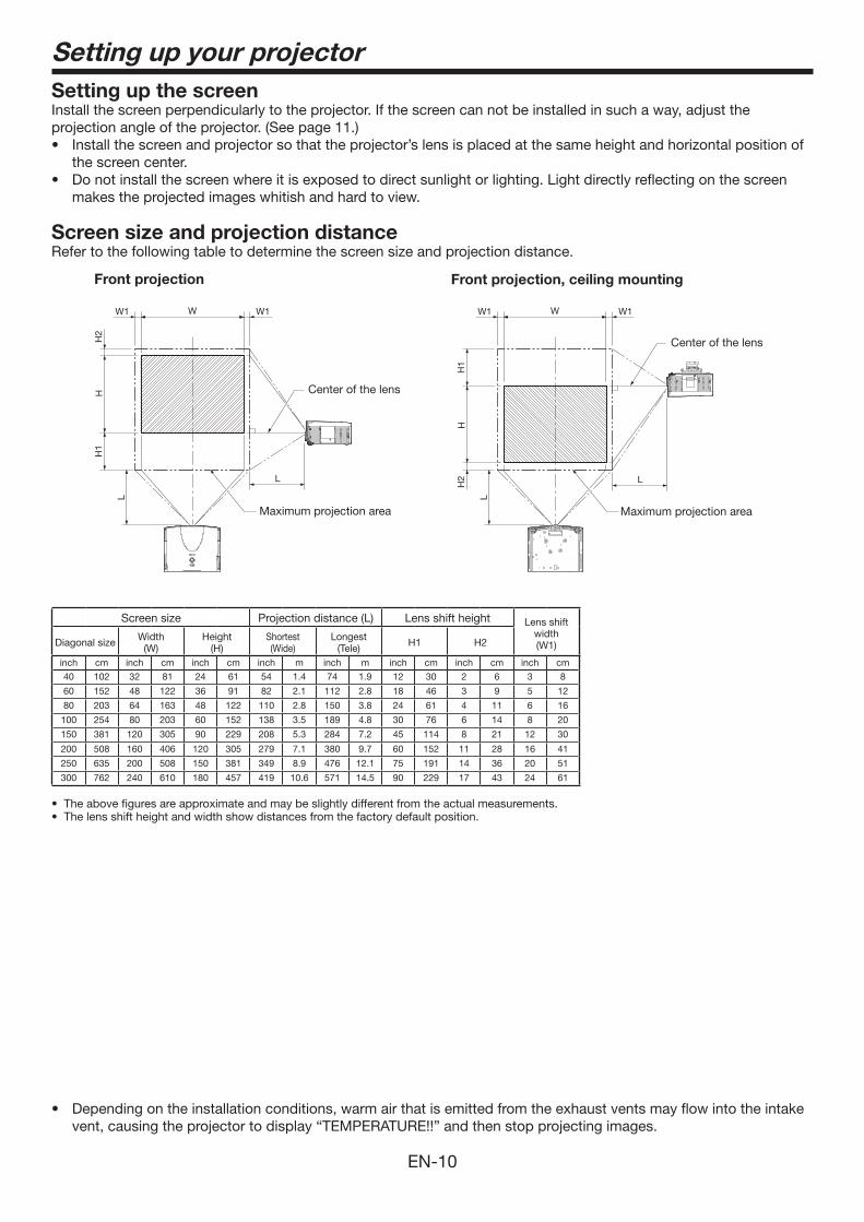
Setting up your projectorSetting up the screenInstall the screen perpendicularly to the projector. If the screen can not be installed in such a way, adjust the projection angle of the projector. (See page 11.)• Installthescreenandprojectorsothattheprojector’slensisplacedatthesameheightandhorizontalpositionof
the screen center. • Donotinstallthescreenwhereitisexposedtodirectsunlightorlighting.Lightdirectlyreflectingonthescreen
makes the projected images whitish and hard to view.
Screen size and projection distance Refer to the following table to determine the screen size and projection distance.
L
L
W1W1
H1
H2
H
W
LL
W1W1
H1
H2
H
W
Center of the lens
Center of the lens
Maximum projection area Maximum projection area
Front projection Front projection, ceiling mounting
• Dependingontheinstallationconditions,warmairthatisemittedfromtheexhaustventsmayflowintotheintakevent, causing the projector to display “TEMPERATURE!!” and then stop projecting images.
Screen size Projection distance (L) Lens shift height Lens shift width (W1)Diagonal size Width
(W)Height
(H)Shortest (Wide)
Longest (Tele) H1 H2
inch cm inch cm inch cm inch m inch m inch cm inch cm inch cm
40 102 32 81 24 61 54 1.4 74 1.9 12 30 2 6 3 8
60 152 48 122 36 91 82 2.1 112 2.8 18 46 3 9 5 12
80 203 64 163 48 122 110 2.8 150 3.8 24 61 4 11 6 16
100 254 80 203 60 152 138 3.5 189 4.8 30 76 6 14 8 20
150 381 120 305 90 229 208 5.3 284 7.2 45 114 8 21 12 30
200 508 160 406 120 305 279 7.1 380 9.7 60 152 11 28 16 41
250 635 200 508 150 381 349 8.9 476 12.1 75 191 14 36 20 51
300 762 240 610 180 457 419 10.6 571 14.5 90 229 17 43 24 61
• Theabovefiguresareapproximateandmaybeslightlydifferentfromtheactualmeasurements.• Thelensshiftheightandwidthshowdistancesfromthefactorydefaultposition.
EN-11
Setting up your projector (continued)
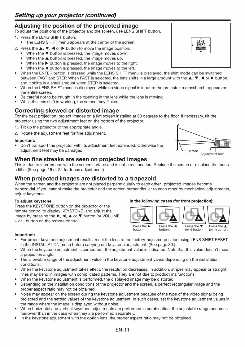
Adjusting the position of the projected imageTo adjust the positions of the projector and the screen, use LENS SHIFT button.
1. Press the LENS SHIFT button.• The LENS SHIFT menu appears at the center of the screen.
2. Press the , , or button to move the image position.• When the button is pressed, the image moves down.• When the button is pressed, the image moves up.• When the button is pressed, the image moves to the right.• When the button is pressed, the image moves to the left.
• WhentheENTERbuttonispressedwhiletheLENSSHIFTmenuisdisplayed,theshiftmodecanbeswitchedbetween FAST and STEP. When FAST is selected, the lens shifts in a large amount with the , , or button, and it shifts in a small amount when STEP is selected.
• WhentheLENSSHIFTmenuisdisplayedwhilenovideosignalisinputtotheprojector,acrosshatchappearsonthe entire screen.
• Becarefulnottobecaughtintheopeninginthelenswhilethelensismoving.• Whilethelensshiftisworking,thescreenmayflicker.
Correcting skewed or distorted imageFor the best projection, project images on a flat screen installed at 90 degrees to the floor. If necessary, tilt the projector using the two adjustment feet on the bottom of the projector.
1. Tilt up the projector to the appropriate angle.
2. Rotate the adjustment feet for fine adjustment.
Important:• Don’ttransporttheprojectorwithitsadjustmentfeetextended.Otherwisethe
adjustment feet may be damaged.
When fine streaks are seen on projected imagesThis is due to interference with the screen surface and is not a malfunction. Replace the screen or displace the focus a little. (See page 16 or 22 for focus adjustment.)
When projected images are distorted to a trapezoidWhen the screen and the projector are not placed perpendicularly to each other, projected images become trapezoidal. If you cannot make the projector and the screen perpendicular to each other by mechanical adjustments, adjust keystone.
To adjust keystone: Press the KEYSTONE button on the projector or the remote control to display KEYSTONE, and adjust the image by pressing the , , or button (or VOLUME +or-buttonontheremotecontrol).
LENSSHIFT
FASTSELECT:ENTER
Adjustment feet Screen
In the following cases (for front projection):
Press the (or -) button.
Press the (or+)button.
Press the button.
Press the button.
Important:• Forproperkeystoneadjustmentresults,resetthelenstothefactory-adjustedpositionusingLENSSHIFTRESET
in the INSTALLATION menu before carrying out keystone adjustment. (See page 30.)• When the keystone adjustment is carried out, the adjustment value is indicated. Note that this value doesn’t mean
a projection angle. • Theallowablerangeoftheadjustmentvalueinthekeystoneadjustmentvariesdependingontheinstallation
conditions. • Whenthekeystoneadjustmenttakeseffect,theresolutiondecreases.Inaddition,stripesmayappearorstraight
lines may bend in images with complicated patterns. They are not due to product malfunctions. • Whenthekeystoneadjustmentisperformed,thedisplayedimagemaybedistorted.• Dependingontheinstallationconditionsoftheprojectorandthescreen,aperfectrectangularimageandthe
proper aspect ratio may not be obtained.• Noisemayappearonthescreenduringthekeystoneadjustmentbecauseofthetypeofthevideosignalbeing
projected and the setting values of the keystone adjustment. In such cases, set the keystone adjustment values in the range where the image is displayed without noise.
• Whenhorizontalandverticalkeystoneadjustmentsareperformedincombination,theadjustablerangebecomesnarrower than in the case when they are performed separately.
• Inthekeystoneadjustmentwiththeoptionlens,theproperaspectratiomaynotbeobtained.
EN-12
Setting up your projector (continued)
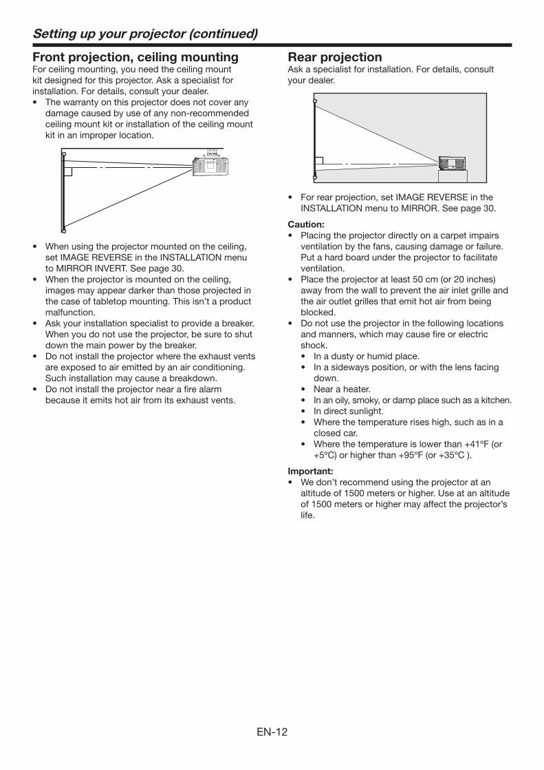
Front projection, ceiling mountingFor ceiling mounting, you need the ceiling mount kit designed for this projector. Ask a specialist for installation. For details, consult your dealer.• Thewarrantyonthisprojectordoesnotcoverany
damage caused by use of any non-recommended ceiling mount kit or installation of the ceiling mount kit in an improper location.
• Whenusingtheprojectormountedontheceiling,set IMAGE REVERSE in the INSTALLATION menu to MIRROR INVERT. See page 30.
• Whentheprojectorismountedontheceiling,images may appear darker than those projected in the case of tabletop mounting. This isn’t a product malfunction.
• Askyourinstallationspecialisttoprovideabreaker. When you do not use the projector, be sure to shut
down the main power by the breaker.• Donotinstalltheprojectorwheretheexhaustvents
are exposed to air emitted by an air conditioning. Such installation may cause a breakdown.• Donotinstalltheprojectornearafirealarm
because it emits hot air from its exhaust vents.
Rear projectionAsk a specialist for installation. For details, consult your dealer.
• Forrearprojection,setIMAGEREVERSEintheINSTALLATION menu to MIRROR. See page 30.
Caution:• Placingtheprojectordirectlyonacarpetimpairs
ventilation by the fans, causing damage or failure. Put a hard board under the projector to facilitate ventilation.
• Placetheprojectoratleast50cm(or20inches)away from the wall to prevent the air inlet grille and the air outlet grilles that emit hot air from being blocked.
• Donotusetheprojectorinthefollowinglocationsand manners, which may cause fire or electric shock.• Inadustyorhumidplace.• Inasidewaysposition,orwiththelensfacing
down.• Nearaheater.• Inanoily,smoky,ordampplacesuchasakitchen.• Indirectsunlight.• Wherethetemperatureriseshigh,suchasina
closed car. • Wherethetemperatureislowerthan+41ºF(or
+5ºC)orhigherthan+95ºF(or+35ºC).
Important:• Wedon’trecommendusingtheprojectoratan
altitude of 1500 meters or higher. Use at an altitude of 1500 meters or higher may affect the projector’s life.
EN-13
2
1
Viewing computer images
2
1
AUDIO OUT
AUDIO IN-1/2
2
1
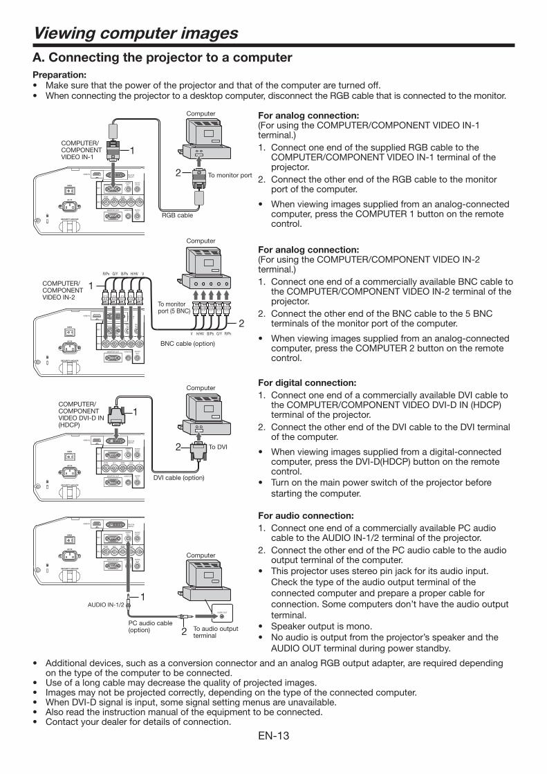
A. Connecting the projector to a computerPreparation: • Makesurethatthepoweroftheprojectorandthatofthecomputerareturnedoff.• Whenconnectingtheprojectortoadesktopcomputer,disconnecttheRGBcablethatisconnectedtothemonitor.
For analog connection: (For using the COMPUTER/COMPONENT VIDEO IN-1 terminal.)1. Connect one end of the supplied RGB cable to the
COMPUTER/COMPONENT VIDEO IN-1 terminal of the projector.
2. Connect the other end of the RGB cable to the monitor port of the computer.
• Whenviewingimagessuppliedfromananalog-connectedcomputer, press the COMPUTER 1 button on the remote control.
For analog connection: (For using the COMPUTER/COMPONENT VIDEO IN-2 terminal.)1. Connect one end of a commercially available BNC cable to
the COMPUTER/COMPONENT VIDEO IN-2 terminal of the projector.
2. Connect the other end of the BNC cable to the 5 BNC terminals of the monitor port of the computer.
• Whenviewingimagessuppliedfromananalog-connectedcomputer, press the COMPUTER 2 button on the remote control.
For digital connection: 1. Connect one end of a commercially available DVI cable to
the COMPUTER/COMPONENT VIDEO DVI-D IN (HDCP) terminal of the projector.
2. Connect the other end of the DVI cable to the DVI terminal of the computer.
• Whenviewingimagessuppliedfromadigital-connectedcomputer, press the DVI-D(HDCP) button on the remote control.
• Turn on the main power switch of the projector before starting the computer.
For audio connection: 1. Connect one end of a commercially available PC audio
cable to the AUDIO IN-1/2 terminal of the projector. 2. Connect the other end of the PC audio cable to the audio
output terminal of the computer.• Thisprojectorusesstereopinjackforitsaudioinput.
Check the type of the audio output terminal of the connected computer and prepare a proper cable for connection. Some computers don’t have the audio output terminal.
• Speakeroutputismono.• Noaudioisoutputfromtheprojector’sspeakerandthe
AUDIO OUT terminal during power standby.
COMPUTER/COMPONENT VIDEO IN-1
COMPUTER/COMPONENT VIDEO DVI-D IN (HDCP)
To monitor port
RGB cable
DVI cable (option)
To DVI
Computer
PC audio cable (option) To audio output
terminal
2
1R/PR G/Y B/PB H/HV V
V H/HV B/PB G/Y R/PR
COMPUTER/COMPONENT VIDEO IN-2
• Additionaldevices,suchasaconversionconnectorandananalogRGBoutputadapter,arerequireddependingon the type of the computer to be connected.
• Useofalongcablemaydecreasethequalityofprojectedimages.• Imagesmaynotbeprojectedcorrectly,dependingonthetypeoftheconnectedcomputer.• WhenDVI-Dsignalisinput,somesignalsettingmenusareunavailable.• Alsoreadtheinstructionmanualoftheequipmenttobeconnected.• Contactyourdealerfordetailsofconnection.
To monitor port (5 BNC)
Computer
Computer
Computer
BNC cable (option)
EN-14
Viewing computer images (continued)
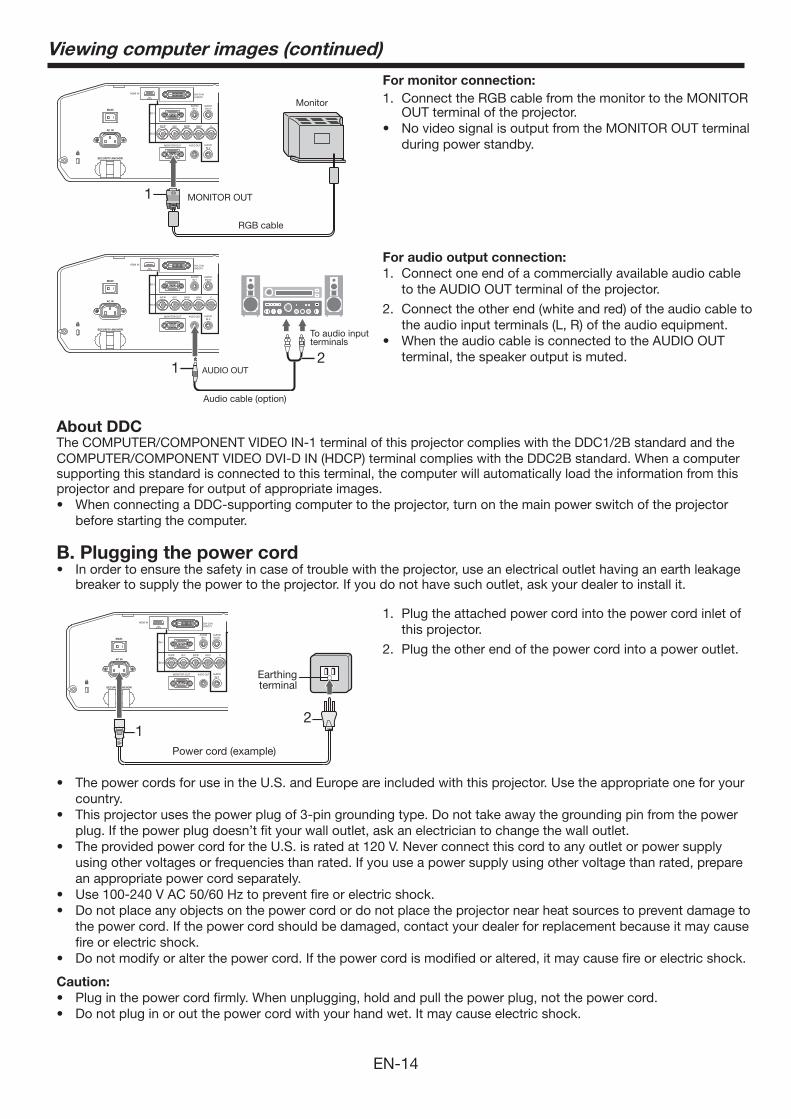
1. Plug the attached power cord into the power cord inlet of this projector.
2. Plug the other end of the power cord into a power outlet.
• ThepowercordsforuseintheU.S.andEuropeareincludedwiththisprojector.Usetheappropriateoneforyourcountry.
• Thisprojectorusesthepowerplugof3-pingroundingtype.Donottakeawaythegroundingpinfromthepowerplug. If the power plug doesn’t fit your wall outlet, ask an electrician to change the wall outlet.
• TheprovidedpowercordfortheU.S.isratedat120V.Neverconnectthiscordtoanyoutletorpowersupplyusing other voltages or frequencies than rated. If you use a power supply using other voltage than rated, prepare an appropriate power cord separately.
• Use 100-240 V AC 50/60 Hz to prevent fire or electric shock.• Do not place any objects on the power cord or do not place the projector near heat sources to prevent damage to
the power cord. If the power cord should be damaged, contact your dealer for replacement because it may cause fire or electric shock.
• Do not modify or alter the power cord. If the power cord is modified or altered, it may cause fire or electric shock.
Caution:• Plug in the power cord firmly. When unplugging, hold and pull the power plug, not the power cord.• Do not plug in or out the power cord with your hand wet. It may cause electric shock.
21
Earthing terminal
Power cord (example)
About DDCThe COMPUTER/COMPONENT VIDEO IN-1 terminal of this projector complies with the DDC1/2B standard and the COMPUTER/COMPONENT VIDEO DVI-D IN (HDCP) terminal complies with the DDC2B standard. When a computer supporting this standard is connected to this terminal, the computer will automatically load the information from this projector and prepare for output of appropriate images. • When connecting a DDC-supporting computer to the projector, turn on the main power switch of the projector
before starting the computer.
1
Monitor
For monitor connection: 1. Connect the RGB cable from the monitor to the MONITOR
OUT terminal of the projector.• NovideosignalisoutputfromtheMONITOROUTterminal
during power standby.
For audio output connection: 1. Connect one end of a commercially available audio cable
to the AUDIO OUT terminal of the projector.
2. Connect the other end (white and red) of the audio cable to the audio input terminals (L, R) of the audio equipment.
• WhentheaudiocableisconnectedtotheAUDIOOUTterminal, the speaker output is muted.
AUDIO OUT2
1
Audio cable (option)
To audio input terminals
MONITOR OUT
RGB cable
B. Plugging the power cord• Inordertoensurethesafetyincaseoftroublewiththeprojector,useanelectricaloutlethavinganearthleakage
breaker to supply the power to the projector. If you do not have such outlet, ask your dealer to install it.
EN-15
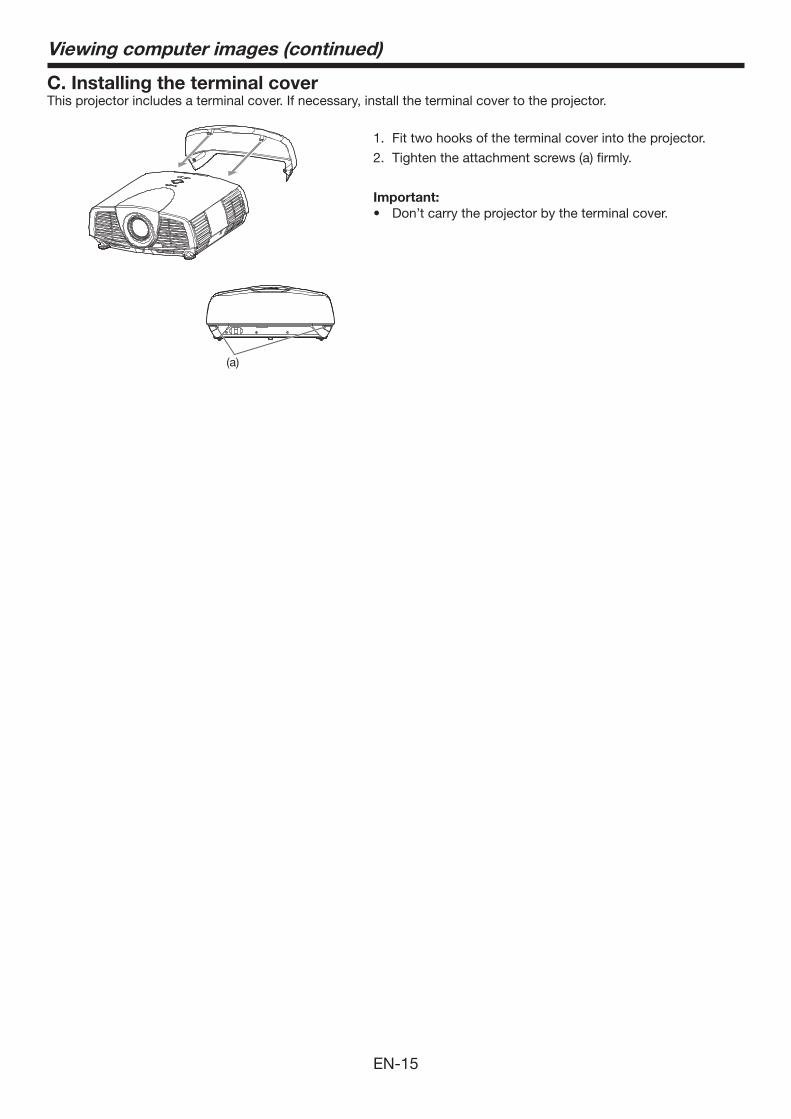
C. Installing the terminal coverThis projector includes a terminal cover. If necessary, install the terminal cover to the projector.
1. Fit two hooks of the terminal cover into the projector.
2. Tighten the attachment screws (a) firmly.
Important:• Don’t carry the projector by the terminal cover.
(a)
Viewing computer images (continued)
EN-16
Viewing computer images (continued)
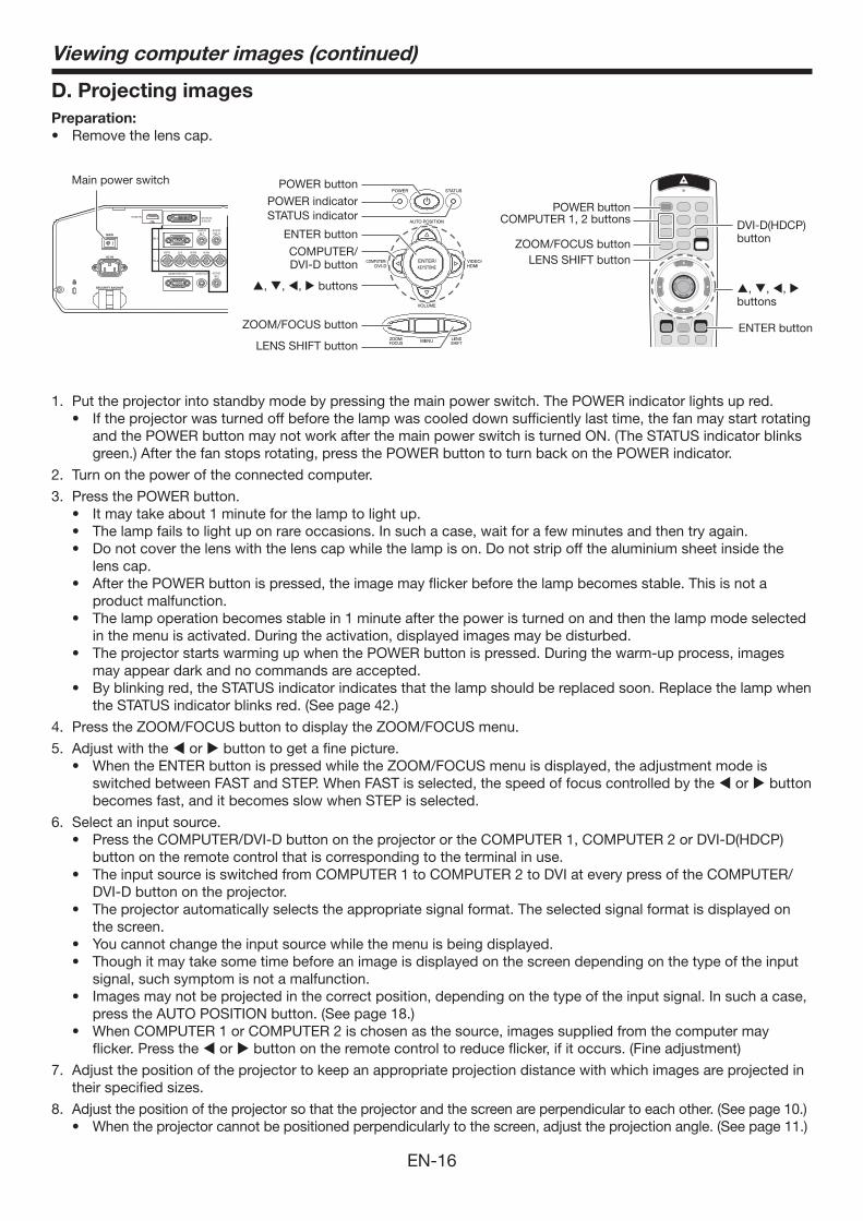
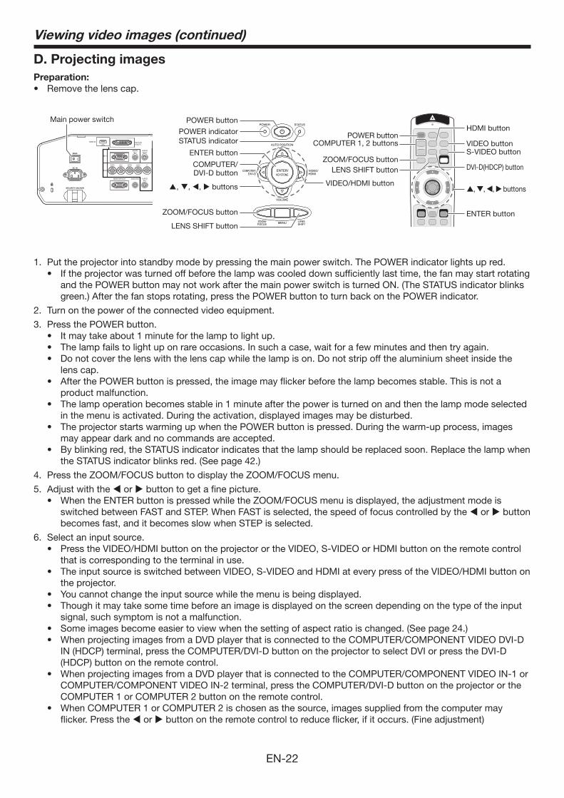
D. Projecting imagesPreparation:• Removethelenscap.
POWER button
COMPUTER/DVI-D button
COMPUTER 1, 2 buttons
LENS SHIFT button
POWER button
ZOOM/FOCUS button
LENS SHIFT button
Main power switch
ZOOM/FOCUS button
DVI-D(HDCP) button
POWER indicatorSTATUS indicator
ENTER button
, , , buttons
ENTER button
, , , buttons
1. Put the projector into standby mode by pressing the main power switch. The POWER indicator lights up red. • Iftheprojectorwasturnedoffbeforethelampwascooleddownsufficientlylasttime,thefanmaystartrotating
and the POWER button may not work after the main power switch is turned ON. (The STATUS indicator blinks green.) After the fan stops rotating, press the POWER button to turn back on the POWER indicator.
2. Turn on the power of the connected computer.
3. Press the POWER button.• Itmaytakeabout1minuteforthelamptolightup.• Thelampfailstolightuponrareoccasions.Insuchacase,waitforafewminutesandthentryagain.• Donotcoverthelenswiththelenscapwhilethelampison.Donotstripoffthealuminiumsheetinsidethe
lens cap. • AfterthePOWERbuttonispressed,theimagemayflickerbeforethelampbecomesstable.Thisisnota
product malfunction. • Thelampoperationbecomesstablein1minuteafterthepoweristurnedonandthenthelampmodeselected
in the menu is activated. During the activation, displayed images may be disturbed.• TheprojectorstartswarmingupwhenthePOWERbuttonispressed.Duringthewarm-upprocess,images
may appear dark and no commands are accepted.• Byblinkingred,theSTATUSindicatorindicatesthatthelampshouldbereplacedsoon.Replacethelampwhen
the STATUS indicator blinks red. (See page 42.)
4. Press the ZOOM/FOCUS button to display the ZOOM/FOCUS menu.
5. Adjust with the or button to get a fine picture. • WhentheENTERbuttonispressedwhiletheZOOM/FOCUSmenuisdisplayed,theadjustmentmodeis
switched between FAST and STEP. When FAST is selected, the speed of focus controlled by the or button becomes fast, and it becomes slow when STEP is selected.
6. Select an input source. • PresstheCOMPUTER/DVI-DbuttonontheprojectorortheCOMPUTER1,COMPUTER2orDVI-D(HDCP)
button on the remote control that is corresponding to the terminal in use. • TheinputsourceisswitchedfromCOMPUTER1toCOMPUTER2toDVIateverypressoftheCOMPUTER/
DVI-D button on the projector. • Theprojectorautomaticallyselectstheappropriatesignalformat.Theselectedsignalformatisdisplayedon
the screen.• Youcannotchangetheinputsourcewhilethemenuisbeingdisplayed.• Thoughitmaytakesometimebeforeanimageisdisplayedonthescreendependingonthetypeoftheinput
signal, such symptom is not a malfunction. • Imagesmaynotbeprojectedinthecorrectposition,dependingonthetypeoftheinputsignal.Insuchacase,
press the AUTO POSITION button. (See page 18.)• WhenCOMPUTER1orCOMPUTER2ischosenasthesource,imagessuppliedfromthecomputermay
flicker. Press the or button on the remote control to reduce flicker, if it occurs. (Fine adjustment)
7. Adjust the position of the projector to keep an appropriate projection distance with which images are projected in their specified sizes.
8. Adjust the position of the projector so that the projector and the screen are perpendicular to each other. (See page 10.) • When the projector cannot be positioned perpendicularly to the screen, adjust the projection angle. (See page 11.)
EN-17
Viewing computer images (continued)
9. Press the ZOOM/FOCUS button to display the ZOOM/FOCUS menu.
10. Adjust with the or button to get an approximate size. • WhentheENTERbuttonispressedwhiletheZOOM/FOCUSmenuisdisplayed,theadjustmentmodeis
switched between FAST and STEP. When FAST is selected, the speed of zoom controlled by the or button becomes fast, and it becomes slow when STEP is selected.
11. Press the LENS SHIFT button. The LENS SHIFT menu appears at the center of the screen.
12.Press the or button to adjust the vertical position and or button to adjust the horizontal position of the displayed image.• Whentheimageisnotdisplayedwithinthescreen,adjusttheprojectionangle.Inaddition,performthe
keystone adjustment, if necessary. (See page 11.)
Repeat steps 4, 5 and 9 to 12, if necessary.
Important:• Focus,zoomandlensshiftadjustmentispossibleinthenormalpicturemodeonly.• Whena16:9imageiskeptdisplayedforalongtimebeforedisplaying4:3image,theafterimagesoftheblackbars
may appear on the 4:3 image screen. Consult your dealer in this case.
To stop projecting:13. Press the POWER button.
• Aconfirmationmessageisdisplayed.• Tocanceltheprocedure,leavetheprojectorforawhileorpressanybuttonexceptthePOWERbutton.
14. Press the POWER button again. • Thelampgoesoutandtheprojectorgoesintoastandbymode.Inthisstandbymode,theSTATUSindicator
blinks green.
15. Wait about 2 minutes for the STATUS indicator to be turned off. • Duringthisperiodof2minutesinthestandbymode,theintakefanandexhaustfanrotatetocoolthelamp.• Theairoutletfansrotatefasterasthetemperaturearoundtheprojectorrises.• Thoughthefansmakeloudsoundsduringcooling,suchsymptomisnotamalfunction.
16. Turn off the main power switch. • ThePOWERindicatorwillgoout.• Ifthemainpowerswitchshouldbeturnedofforthepowercordshouldbeunpluggedaccidentallywhileeither
the air inlet fan or the air outlet fans are operating or the lamp is on, allow the projector to cool down for 10 minutes with the power off. To light the lamp again, press the POWER button. If the lamp doesn’t light up immediately, repeat pressing the POWER button 2 or 3 times. If it should still fail to light up, replace the lamp.
• Coverthelenswiththelenscaptoprotectitfromdust.• Forsafety’ssake,unplugthepowercordfromtheoutlet.• Whenyourepeatturningoffthemainswitchwithin30minutesfromthelampillumination,anerrormayoccur
in the clock function of this product.
Instant Shut DownYou can turn off this projector just by turning off the power switch or unplugging the power cord without pressing the POWER button. • Don’tshutdowntheprojectorwhiletheSTATUSindicatorisblinkingafterthelamplightsupbecausethelamp’s
life may be shortened. • Don’tturntheprojectorbackonrightaftershuttingitdownbecausethelamp'slifemaybeshortened.(Waitabout
10 minutes before turning the projector back on.) • Beforeshuttingdowntheprojector,besuretoclosethemenuscreen.Ifyoushutdowntheprojectorwithout
closing the menu, the setting data of the menu may not be saved. • Ifyoushutdowntheprojectorwhilecontrollingtheprojectorusingthenetworkfunction,theapplicationsoftware
such as ProjectorView may fail. For details, see “User Guide of LAN Control Utility” contained in the CD-ROM.
EN-18
AV muteThe video and audio signals are temporarily muted when the AV MUTE button is pressed. To cancel muting, press the AV MUTE button again.• Ittakesseveralsecondsbeforemutingiscompletelycanceled.• IfAVMUTEMODEintheINSTALLATIONmenuissettoIMAGE,thesplashscreenwillappearwhentheAVMUTE
button is pressed. • Youcanalterthesplashscreenoptionally.Seepage37.• TheaudiofromtheAUDIOOUTterminalisalsomutedbypressingtheAVMUTEbutton.
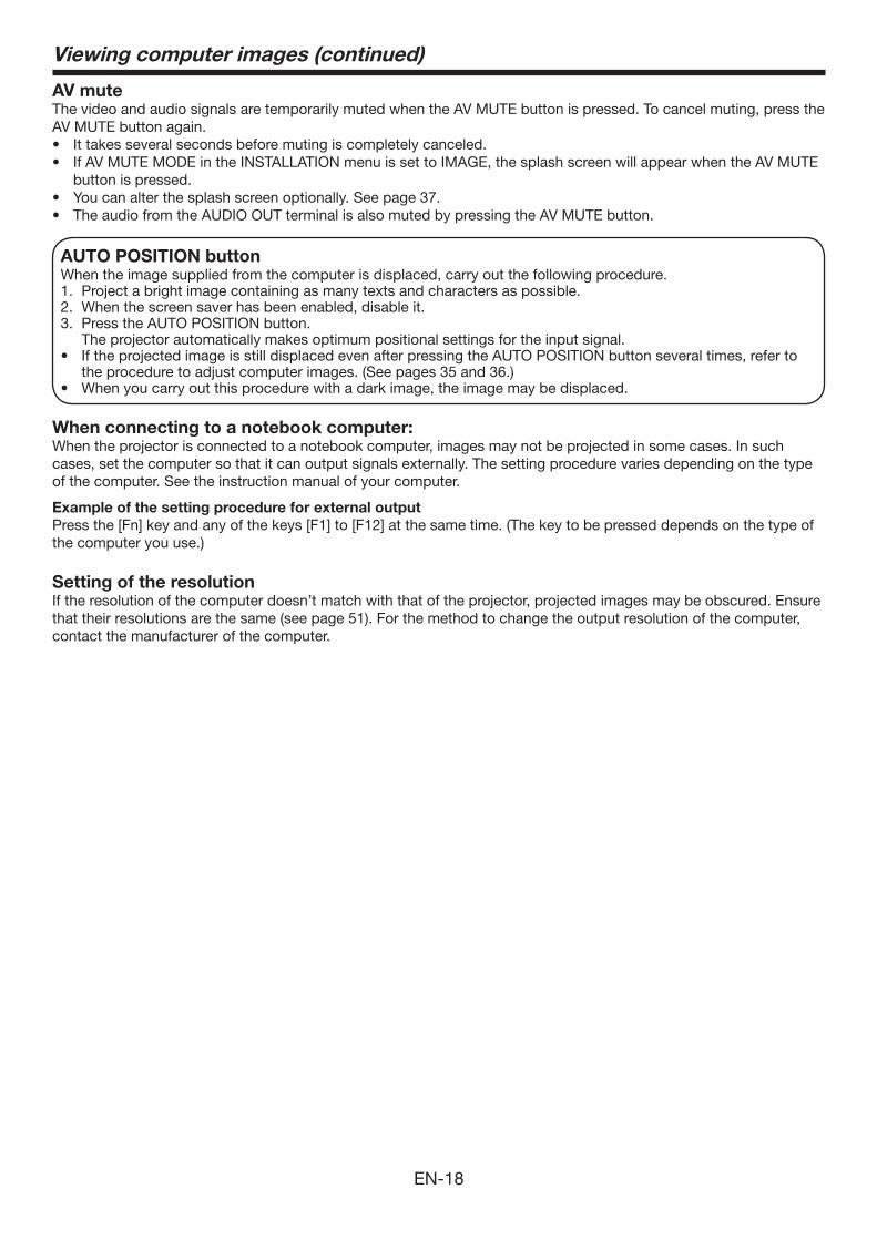
AUTO POSITION button When the image supplied from the computer is displaced, carry out the following procedure. 1. Project a bright image containing as many texts and characters as possible. 2. When the screen saver has been enabled, disable it. 3. Press the AUTO POSITION button. The projector automatically makes optimum positional settings for the input signal. • IftheprojectedimageisstilldisplacedevenafterpressingtheAUTOPOSITIONbuttonseveraltimes,referto
the procedure to adjust computer images. (See pages 35 and 36.)• Whenyoucarryoutthisprocedurewithadarkimage,theimagemaybedisplaced.
When connecting to a notebook computer:When the projector is connected to a notebook computer, images may not be projected in some cases. In such cases, set the computer so that it can output signals externally. The setting procedure varies depending on the type of the computer. See the instruction manual of your computer.
Example of the setting procedure for external outputPress the [Fn] key and any of the keys [F1] to [F12] at the same time. (The key to be pressed depends on the type of the computer you use.)
Setting of the resolutionIf the resolution of the computer doesn’t match with that of the projector, projected images may be obscured. Ensure that their resolutions are the same (see page 51). For the method to change the output resolution of the computer, contact the manufacturer of the computer.
Viewing computer images (continued)
EN-19
Viewing video images
Connecting to a video player, etc.
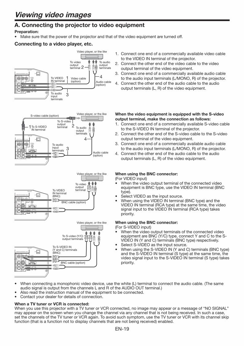
1. Connect one end of a commercially available video cable to the VIDEO IN terminal of the projector.
2. Connect the other end of the video cable to the video output terminal of the video equipment.
3. Connect one end of a commercially available audio cable to the audio input terminals (L/MONO, R) of the projector.
4. Connect the other end of the audio cable to the audio output terminals (L, R) of the video equipment.
When the video equipment is equipped with the S-video output terminal, make the connection as follows: 1. Connect one end of a commercially available S-video cable
to the S-VIDEO IN terminal of the projector. 2. Connect the other end of the S-video cable to the S-video
output terminal of the video equipment. 3. Connect one end of a commercially available audio cable
to the audio input terminals (L/MONO, R) of the projector. 4. Connect the other end of the audio cable to the audio
output terminals (L, R) of the video equipment.
When using the BNC connector:(For VIDEO input)• When the video output terminal of the connected video
equipment is BNC type, use the VIDEO IN terminal (BNC type).
• SelectVIDEOastheinputsource.• When using the VIDEO IN terminal (BNC type) and the
VIDEO IN terminal (RCA type) at the same time, the video signal input to the VIDEO IN terminal (RCA type) takes priority.
When using the BNC connector:(For S-VIDEO input)• When the video output terminals of the connected video
equipment are BNC (Y/C) type, connect Y and C to the S-VIDEO IN (Y and C) terminals (BNC type) respectively.
• SelectS-VIDEOastheinputsource.• When using the S-VIDEO IN (Y and C) terminals (BNC type)
and the S-VIDEO IN terminal (S type) at the same time, the video signal input to the S-VIDEO IN terminal (S type) takes priority.
• Whenconnectingamonophonicvideodevice,usethewhite(L)terminaltoconnecttheaudiocable.(Thesameaudio signal is output from the channels L and R of the AUDIO OUT terminal.)
• Alsoreadtheinstructionmanualoftheequipmenttobeconnected.• Contactyourdealerfordetailsofconnection.
When a TV tuner or VCR is connected:When you use this projector with a TV tuner or VCR connected, no image may appear or a message of “NO SIGNAL” may appear on the screen when you change the channel via any channel that is not being received. In such a case, set the channels of the TV tuner or VCR again. To avoid such symptom, use the TV tuner or VCR with its channel skip function (that is a function not to display channels that are not being received) enabled.
A. Connecting the projector to video equipmentPreparation:• Make sure that the power of the projector and that of the video equipment are turned off.
3
4
1 2
1 4
2
3
To VIDEO IN terminal
To video output terminal
Video player, or the like
To S-VIDEO IN terminal
S-video cable (option)
To S-video output terminal
Video player, or the like
Audio cable(option)
To audio input terminals
To audio output terminals
To audio input terminals
Audio cable (option)
To audio output terminals
To VIDEO IN terminal (BNC)
BNC cable (option)
To video output terminal
Video player, or the like
To S-VIDEO IN (Y and C) terminals (BNC)
BNC cable (option)
To S-video (Y/C) output terminals
Video player, or the like
Video cable(option)
EN-20
Viewing video images (continued)
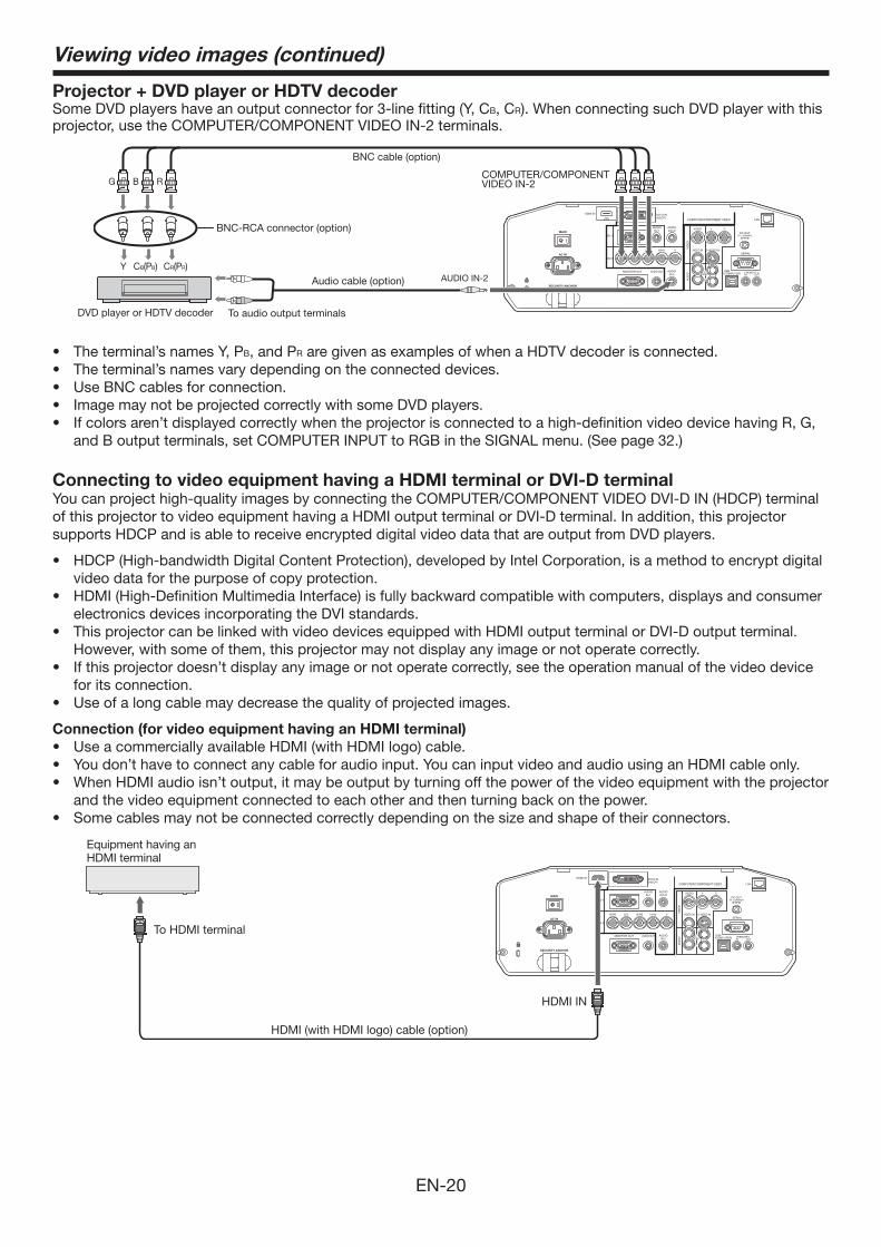
Projector + DVD player or HDTV decoderSome DVD players have an output connector for 3-line fitting (Y, CB, CR). When connecting such DVD player with this projector, use the COMPUTER/COMPONENT VIDEO IN-2 terminals.
CB(PB)Y CR(PR)
B G R
AUDIO IN-2
BNC cable (option)
DVD player or HDTV decoder
BNC-RCA connector (option)
COMPUTER/COMPONENT VIDEO IN-2
Audio cable (option)
To audio output terminals
• Theterminal’snamesY,PB, and PR are given as examples of when a HDTV decoder is connected.• Theterminal’snamesvarydependingontheconnecteddevices.• UseBNCcablesforconnection.• ImagemaynotbeprojectedcorrectlywithsomeDVDplayers.• Ifcolorsaren’tdisplayedcorrectlywhentheprojectorisconnectedtoahigh-definitionvideodevicehavingR,G,
and B output terminals, set COMPUTER INPUT to RGB in the SIGNAL menu. (See page 32.)
Connecting to video equipment having a HDMI terminal or DVI-D terminalYou can project high-quality images by connecting the COMPUTER/COMPONENT VIDEO DVI-D IN (HDCP) terminal of this projector to video equipment having a HDMI output terminal or DVI-D terminal. In addition, this projector supports HDCP and is able to receive encrypted digital video data that are output from DVD players.
• HDCP (High-bandwidth Digital Content Protection), developed by Intel Corporation, is a method to encrypt digital video data for the purpose of copy protection.
• HDMI (High-Definition Multimedia Interface) is fully backward compatible with computers, displays and consumer electronics devices incorporating the DVI standards.
• This projector can be linked with video devices equipped with HDMI output terminal or DVI-D output terminal. However, with some of them, this projector may not display any image or not operate correctly.
• If this projector doesn’t display any image or not operate correctly, see the operation manual of the video device for its connection.
• Use of a long cable may decrease the quality of projected images.
Connection (for video equipment having an HDMI terminal)• Use a commercially available HDMI (with HDMI logo) cable.• Youdon’thavetoconnectanycableforaudioinput.YoucaninputvideoandaudiousinganHDMIcableonly.• WhenHDMIaudioisn’toutput,itmaybeoutputbyturningoffthepowerofthevideoequipmentwiththeprojector
and the video equipment connected to each other and then turning back on the power.• Somecablesmaynotbeconnectedcorrectlydependingonthesizeandshapeoftheirconnectors.
Equipment having an HDMI terminal
To HDMI terminal
HDMI IN
HDMI (with HDMI logo) cable (option)
EN-21
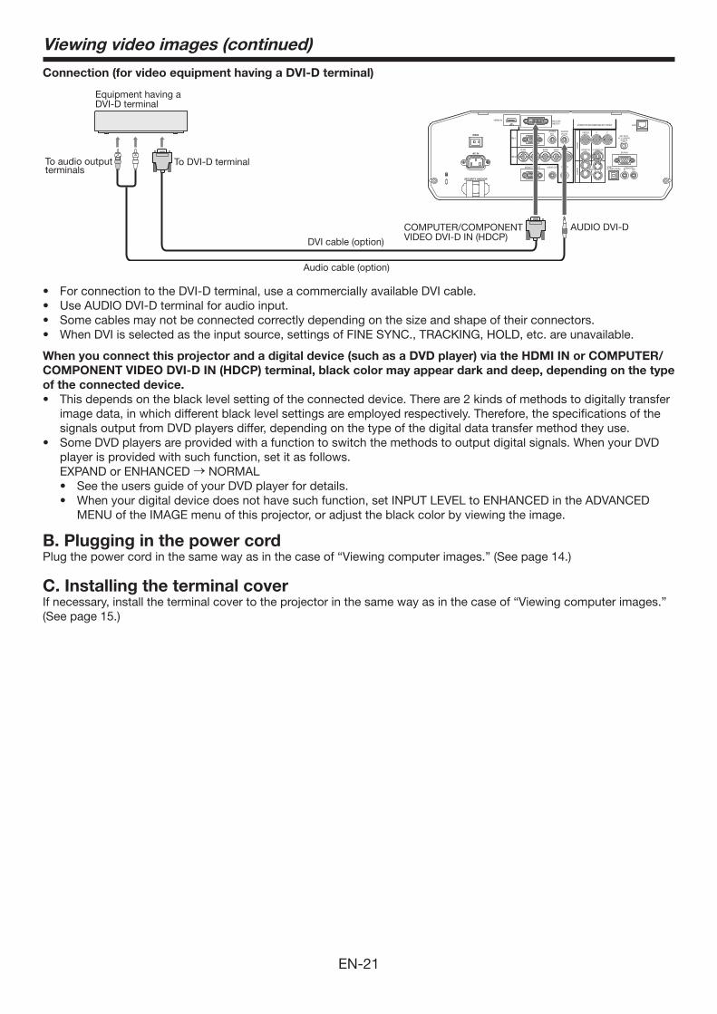
Connection (for video equipment having a DVI-D terminal)
Equipment having a DVI-D terminal
Audio cable (option)
To DVI-D terminal
DVI cable (option)
COMPUTER/COMPONENT VIDEO DVI-D IN (HDCP)
To audio output terminals
AUDIO DVI-D
• ForconnectiontotheDVI-Dterminal,useacommerciallyavailableDVIcable.• UseAUDIODVI-Dterminalforaudioinput.• Somecablesmaynotbeconnectedcorrectlydependingonthesizeandshapeoftheirconnectors.• WhenDVIisselectedastheinputsource,settingsofFINESYNC.,TRACKING,HOLD,etc.areunavailable.
When you connect this projector and a digital device (such as a DVD player) via the HDMI IN or COMPUTER/COMPONENT VIDEO DVI-D IN (HDCP) terminal, black color may appear dark and deep, depending on the type of the connected device. • Thisdependsontheblacklevelsettingoftheconnecteddevice.Thereare2kindsofmethodstodigitallytransfer
image data, in which different black level settings are employed respectively. Therefore, the specifications of the signals output from DVD players differ, depending on the type of the digital data transfer method they use.
• SomeDVDplayersareprovidedwithafunctiontoswitchthemethodstooutputdigitalsignals.WhenyourDVDplayer is provided with such function, set it as follows.
EXPAND or ENHANCED → NORMAL• SeetheusersguideofyourDVDplayerfordetails.• Whenyourdigitaldevicedoesnothavesuchfunction,setINPUTLEVELtoENHANCEDintheADVANCED
MENU of the IMAGE menu of this projector, or adjust the black color by viewing the image.
B. Plugging in the power cordPlug the power cord in the same way as in the case of “Viewing computer images.” (See page 14.)
C. Installing the terminal coverIf necessary, install the terminal cover to the projector in the same way as in the case of “Viewing computer images.” (See page 15.)
Viewing video images (continued)
EN-22
Viewing video images (continued)
D. Projecting imagesPreparation:• Removethelenscap.
POWER button
COMPUTER/DVI-D button
COMPUTER 1, 2 buttons
LENS SHIFT button
POWER button
ZOOM/FOCUS button
LENS SHIFT button
Main power switch
ZOOM/FOCUS button
POWER indicatorSTATUS indicator
ENTER button
, , , buttons
ENTER button
, , , buttonsVIDEO/HDMI button
DVI-D(HDCP) button
S-VIDEO buttonVIDEO button
HDMI button
1. Put the projector into standby mode by pressing the main power switch. The POWER indicator lights up red. • Iftheprojectorwasturnedoffbeforethelampwascooleddownsufficientlylasttime,thefanmaystartrotating
and the POWER button may not work after the main power switch is turned ON. (The STATUS indicator blinks green.) After the fan stops rotating, press the POWER button to turn back on the POWER indicator.
2. Turn on the power of the connected video equipment.
3. Press the POWER button.• Itmaytakeabout1minuteforthelamptolightup.• Thelampfailstolightuponrareoccasions.Insuchacase,waitforafewminutesandthentryagain.• Donotcoverthelenswiththelenscapwhilethelampison.Donotstripoffthealuminiumsheetinsidethe
lens cap. • AfterthePOWERbuttonispressed,theimagemayflickerbeforethelampbecomesstable.Thisisnota
product malfunction. • Thelampoperationbecomesstablein1minuteafterthepoweristurnedonandthenthelampmodeselected
in the menu is activated. During the activation, displayed images may be disturbed.• TheprojectorstartswarmingupwhenthePOWERbuttonispressed.Duringthewarm-upprocess,images
may appear dark and no commands are accepted.• Byblinkingred,theSTATUSindicatorindicatesthatthelampshouldbereplacedsoon.Replacethelampwhen
the STATUS indicator blinks red. (See page 42.)
4. Press the ZOOM/FOCUS button to display the ZOOM/FOCUS menu.
5. Adjust with the or button to get a fine picture. • WhentheENTERbuttonispressedwhiletheZOOM/FOCUSmenuisdisplayed,theadjustmentmodeis
switched between FAST and STEP. When FAST is selected, the speed of focus controlled by the or button becomes fast, and it becomes slow when STEP is selected.
6. Select an input source. • PresstheVIDEO/HDMIbuttonontheprojectorortheVIDEO,S-VIDEOorHDMIbuttonontheremotecontrol
that is corresponding to the terminal in use. • TheinputsourceisswitchedbetweenVIDEO,S-VIDEOandHDMIateverypressoftheVIDEO/HDMIbuttonon
the projector. • Youcannotchangetheinputsourcewhilethemenuisbeingdisplayed.• Thoughitmaytakesometimebeforeanimageisdisplayedonthescreendependingonthetypeoftheinput
signal, such symptom is not a malfunction. • Someimagesbecomeeasiertoviewwhenthesettingofaspectratioischanged.(Seepage24.)• WhenprojectingimagesfromaDVDplayerthatisconnectedtotheCOMPUTER/COMPONENTVIDEODVI-D
IN (HDCP) terminal, press the COMPUTER/DVI-D button on the projector to select DVI or press the DVI-D (HDCP) button on the remote control.
• WhenprojectingimagesfromaDVDplayerthatisconnectedtotheCOMPUTER/COMPONENTVIDEOIN-1orCOMPUTER/COMPONENT VIDEO IN-2 terminal, press the COMPUTER/DVI-D button on the projector or the COMPUTER 1 or COMPUTER 2 button on the remote control.
• WhenCOMPUTER1orCOMPUTER2ischosenasthesource,imagessuppliedfromthecomputermayflicker. Press the or button on the remote control to reduce flicker, if it occurs. (Fine adjustment)
EN-23
7. Adjust the position of the projector to keep an appropriate projection distance with which images are projected in their specified sizes.
8. Adjust the position of the projector so that the projector and the screen are perpendicular to each other. (See page 10.) • Whentheprojectorcannotbepositionedperpendicularlytothescreen,adjusttheprojectionangle.(Seepage
11.)
9. Press the ZOOM/FOCUS button to display the ZOOM/FOCUS menu.
10. Adjust with the or button to get an approximate size. • When the ENTER button is pressed while the ZOOM/FOCUS menu is displayed, the adjustment mode is
switched between FAST and STEP. When FAST is selected, the speed of zoom controlled by the or button becomes fast, and it becomes slow when STEP is selected.
11. Press the LENS SHIFT button. The LENS SHIFT menu appears at the center of the screen.
12. Press the or button to adjust the vertical position and or button to adjust the horizontal position of the displayed image.• Whentheimageisnotdisplayedwithinthescreen,adjusttheprojectionangle.Inaddition,performthe
keystone adjustment, if necessary. (See page 11.)
Repeat steps 4, 5 and 9 to 12, if necessary.
Important:• Focus,zoomandlensshiftadjustmentispossibleinthenormalpicturemodeonly.
To stop projecting:13. Press the POWER button.
• Aconfirmationmessageisdisplayed.• Tocanceltheprocedure,leavetheprojectorforawhileorpressanybuttonexceptthePOWERbutton.
14. Press the POWER button again. • Thelampgoesoutandtheprojectorgoesintoastandbymode.Inthisstandbymode,theSTATUSindicator
blinks green.
15. Wait about 2 minutes for the STATUS indicator to be turned off. • Duringthisperiodof2minutesinthestandbymode,theintakefanandexhaustfanrotatetocoolthelamp.• Theairoutletfansrotatefasterasthetemperaturearoundtheprojectorrises.• Thoughthefansmakeloudsoundsduringcooling,suchsymptomisnotamalfunction.
16. Turn off the main power switch. • ThePOWERindicatorwillgoout.• Ifthemainpowerswitchshouldbeturnedofforthepowercordshouldbeunpluggedaccidentallywhileeither
the air inlet fan or the air outlet fans are operating or the lamp is on, allow the projector to cool down for 10 minutes with the power off. To light the lamp again, press the POWER button. If the lamp doesn’t light up immediately, repeat pressing the POWER button 2 or 3 times. If it should still fail to light up, replace the lamp.
• Coverthelenswiththelenscaptoprotectitfromdust.• Forsafety’ssake,unplugthepowercordfromtheoutlet.• Whenyourepeatturningoffthemainswitchwithin30minutesfromthelampillumination,anerrormayoccur
in the clock function of this product.
Instant Shut DownYou can turn off this projector just by turning off the power switch or unplugging the power cord without pressing the POWER button. • Don’tshutdowntheprojectorwhiletheSTATUSindicatorisblinkingafterthelamplightsupbecausethelamp’s
life may be shortened. • Don’tturntheprojectorbackonrightaftershuttingitdownbecausethelamp’slifemaybeshortened.(Waitabout
10 minutes before turning the projector back on.) • Beforeshuttingdowntheprojector,besuretoclosethemenuscreen.Ifyoushutdowntheprojectorwithout
closing the menu, the setting data of the menu may not be saved. • Ifyoushutdowntheprojectorwhilecontrollingtheprojectorusingthenetworkfunction,theapplicationsoftware
such as ProjectorView may fail. For details, see “User Guide of LAN Control Utility” contained in the CD-ROM.
Viewing video images (continued)
EN-24
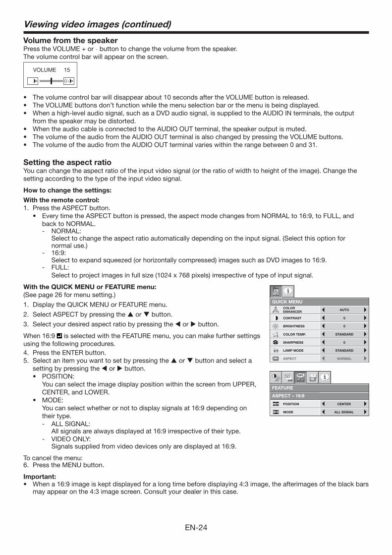
Volume from the speakerPresstheVOLUME+or- button to change the volume from the speaker.The volume control bar will appear on the screen.
VOLUME 15
• Thevolumecontrolbarwilldisappearabout10secondsaftertheVOLUMEbuttonisreleased.• TheVOLUMEbuttonsdon’tfunctionwhilethemenuselectionbarorthemenuisbeingdisplayed.• Whenahigh-levelaudiosignal,suchasaDVDaudiosignal,issuppliedtotheAUDIOINterminals,theoutput
from the speaker may be distorted.• WhentheaudiocableisconnectedtotheAUDIOOUTterminal,thespeakeroutputismuted.• ThevolumeoftheaudiofromtheAUDIOOUTterminalisalsochangedbypressingtheVOLUMEbuttons.• ThevolumeoftheaudiofromtheAUDIOOUTterminalvarieswithintherangebetween0and31.
Setting the aspect ratioYou can change the aspect ratio of the input video signal (or the ratio of width to height of the image). Change the setting according to the type of the input video signal.
How to change the settings:With the remote control:1. Press the ASPECT button.
• EverytimetheASPECTbuttonispressed,theaspectmodechangesfromNORMALto16:9,toFULL,andback to NORMAL. - NORMAL: Select to change the aspect ratio automatically depending on the input signal. (Select this option for
normal use.) - 16:9: Select to expand squeezed (or horizontally compressed) images such as DVD images to 16:9. - FULL: Select to project images in full size (1024 x 768 pixels) irrespective of type of input signal.
With the QUICK MENU or FEATURE menu:(See page 26 for menu setting.)
1. Display the QUICK MENU or FEATURE menu.
2. Select ASPECT by pressing the or button.
3. Select your desired aspect ratio by pressing the or button.
When 16:9 is selected with the FEATURE menu, you can make further settings using the following procedures.4. Press the ENTER button. 5. Select an item you want to set by pressing the or button and select a
setting by pressing the or button.• POSITION: You can select the image display position within the screen from UPPER,
CENTER, and LOWER.• MODE: You can select whether or not to display signals at 16:9 depending on
their type.- ALL SIGNAL: All signals are always displayed at 16:9 irrespective of their type. - VIDEO ONLY: Signals supplied from video devices only are displayed at 16:9.
To cancel the menu:6. Press the MENU button.
Important:• Whena16:9imageiskeptdisplayedforalongtimebeforedisplaying4:3image,theafterimagesoftheblackbars
may appear on the 4:3 image screen. Consult your dealer in this case.
NORMALASPECT
LAMP MODE STANDARD
QUICK MENU
CONTRAST
BRIGHTNESS
0
0
STANDARD
COLOR
0COLOR
COLOR TEMP.
0SHARPNESS
AUTOCOLORENHANCER
SELECTUSER MENU
OKDETAIL MENU
Viewing video images (continued)
ASPECT – 16:9
ALL SIGNAL
CENTERPOSITION
MODE
FEATURE
opt.
EN-25
Menu operationYou can make various settings using the displayed menus.
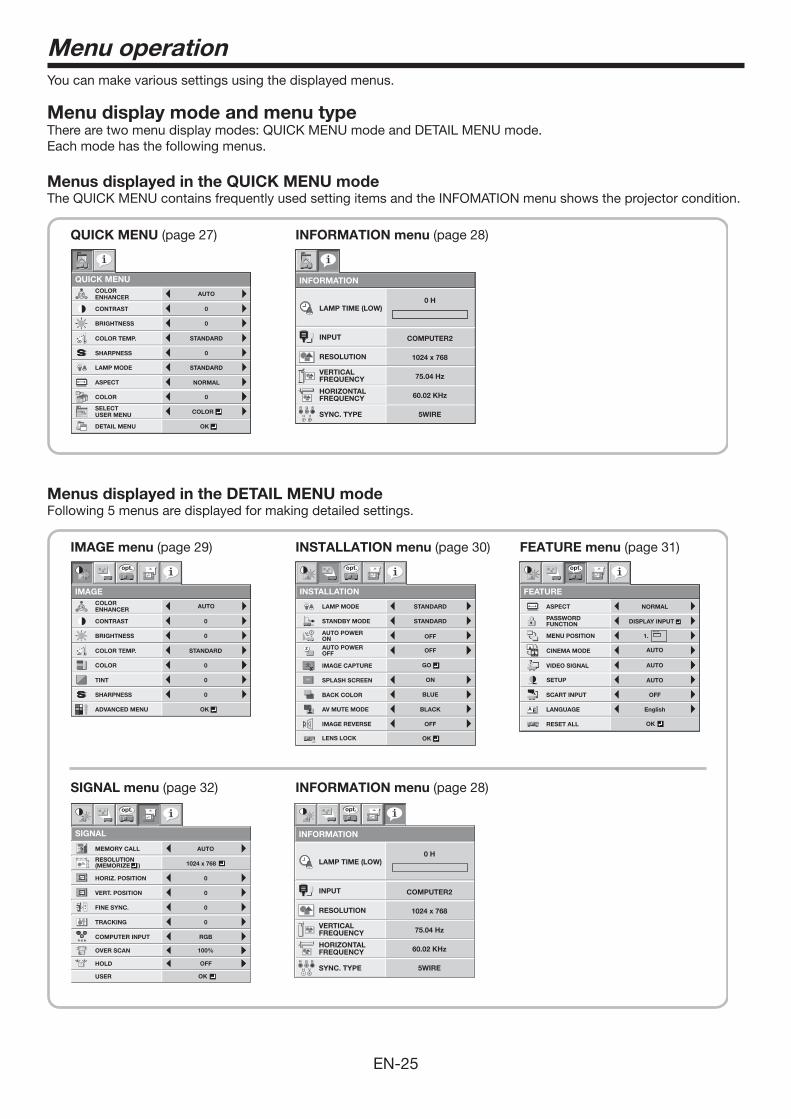
Menu display mode and menu typeThere are two menu display modes: QUICK MENU mode and DETAIL MENU mode.Each mode has the following menus.
Menus displayed in the QUICK MENU modeThe QUICK MENU contains frequently used setting items and the INFOMATION menu shows the projector condition.
QUICK MENU (page 27) INFORMATION menu (page 28)
INFORMATION
LAMP TIME (LOW)
INPUT
RESOLUTION
VERTICALFREQUENCY
HORIZONTALFREQUENCY
SYNC. TYPE 5WIRE
60.02 KHz
75.04 Hz
1024 x 768
COMPUTER2
0 H
R G
H V
B
NORMALASPECT
LAMP MODE STANDARD
QUICK MENU
CONTRAST
BRIGHTNESS
0
0
STANDARD
COLOR
0COLOR
COLOR TEMP.
0SHARPNESS
AUTOCOLORENHANCER
SELECTUSER MENU
OKDETAIL MENU
Menus displayed in the DETAIL MENU modeFollowing 5 menus are displayed for making detailed settings.
FEATURE menu (page 31)
SIGNAL menu (page 32) INFORMATION menu (page 28)
IMAGE menu (page 29) INSTALLATION menu (page 30)
R G BR G B
SIGNAL
HORIZ. POSITION 0
VERT. POSITION 0
TRACKING 0
COMPUTER INPUT RGB
FINE SYNC. 0
USER
opt.
OK
OFFHOLD
100%OVER SCAN
MEMORY CALL AUTO
RESOLUTION(MEMORIZE ) 1024 x 768V
H
AU
IMAGE
opt.
CONTRAST
BRIGHTNESS
0
0
STANDARD
0
0COLOR
TINT
COLOR TEMP.
0SHARPNESS
AUTOCOLORENHANCER
OKADVANCED MENU
INSTALLATION
opt.
LAMP MODE
OFFAUTO POWER ON
STANDARD
STANDBY MODE STANDARD
ON ON
AUTO POWER OFF OFF
BACK COLOR
SPLASH SCREEN
BLUE
OFF
BLACKAV MUTE MODE
IMAGE REVERSE
GO
LENS LOCK OK
INFORMATION
opt.
LAMP TIME (LOW)
INPUT
RESOLUTION
VERTICALFREQUENCY
HORIZONTALFREQUENCY
SYNC. TYPE 5WIRE
60.02 KHz
75.04 Hz
1024 x 768
COMPUTER2
0 H
R G
H V
B
IMAGE CAPTURE
FEATURE
NORMAL
opt.
MENU POSITION
VIDEO SIGNAL?
ASPECT
RESET ALL
EnglishLANGUAGEA Ë
OK
SCART INPUT
DISPLAY INPUTPASSWORDFUNCTION
CINEMA MODE
1.
SETUP AUTO
OFF
AUTO
AUTO
EN-26
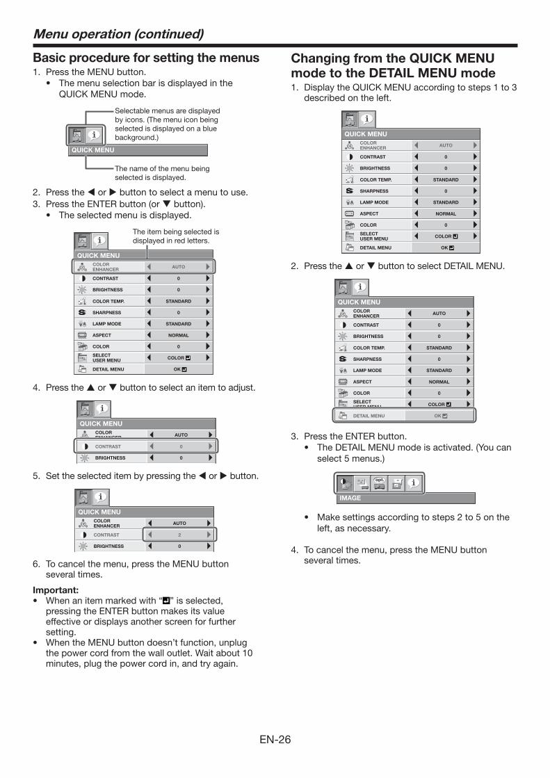
Basic procedure for setting the menus1. Press the MENU button.
• ThemenuselectionbarisdisplayedintheQUICK MENU mode.
QUICK MENU
Selectable menus are displayed by icons. (The menu icon being selected is displayed on a blue background.)
The name of the menu being selected is displayed.
2. Press the or button to select a menu to use.3. Press the ENTER button (or button).
• Theselectedmenuisdisplayed.
NORMALASPECT
LAMP MODE STANDARD
QUICK MENU
CONTRAST
BRIGHTNESS
0
0
STANDARD
COLOR
0COLOR
COLOR TEMP.
0SHARPNESS
AUTOCOLORENHANCER
SELECTUSER MENU
OKDETAIL MENU
The item being selected is displayed in red letters.
4. Press the or button to select an item to adjust.
NORMALASPECT
LAMP MODE STANDARD
QUICK MENU
CONTRAST
BRIGHTNESS
0
0
STANDARD
COLOR
0COLOR
COLOR TEMP.
0SHARPNESS
AUTOCOLORENHANCER
SELECTUSER MENU
OKDETAIL MENU
5. Set the selected item by pressing the or button.
NORMALASPECT
LAMP MODE STANDARD
QUICK MENU
CONTRAST
BRIGHTNESS
2
0
STANDARD
COLOR
0COLOR
COLOR TEMP.
0SHARPNESS
AUTOCOLORENHANCER
SELECTUSER MENU
OKDETAIL MENU
6. To cancel the menu, press the MENU button several times.
Important:• When an item marked with “ ” is selected,
pressing the ENTER button makes its value effective or displays another screen for further setting.
• When the MENU button doesn’t function, unplug the power cord from the wall outlet. Wait about 10 minutes, plug the power cord in, and try again.
Changing from the QUICK MENU mode to the DETAIL MENU mode1. Display the QUICK MENU according to steps 1 to 3
described on the left.
NORMALASPECT
LAMP MODE STANDARD
QUICK MENU
CONTRAST
BRIGHTNESS
0
0
STANDARD
COLOR
0COLOR
COLOR TEMP.
0SHARPNESS
AUTOCOLORENHANCER
SELECTUSER MENU
OKDETAIL MENU
2. Press the or button to select DETAIL MENU.
NORMALASPECT
LAMP MODE STANDARD
QUICK MENU
CONTRAST
BRIGHTNESS
0
0
STANDARD
COLOR
0COLOR
COLOR TEMP.
0SHARPNESS
AUTOCOLORENHANCER
SELECTUSER MENU
OKDETAIL MENU
3. Press the ENTER button.• TheDETAILMENUmodeisactivated.(Youcan
select 5 menus.)
IMAGE
opt.
• Makesettingsaccordingtosteps2to5ontheleft, as necessary.
4. To cancel the menu, press the MENU button several times.
Menu operation (continued)
EN-27
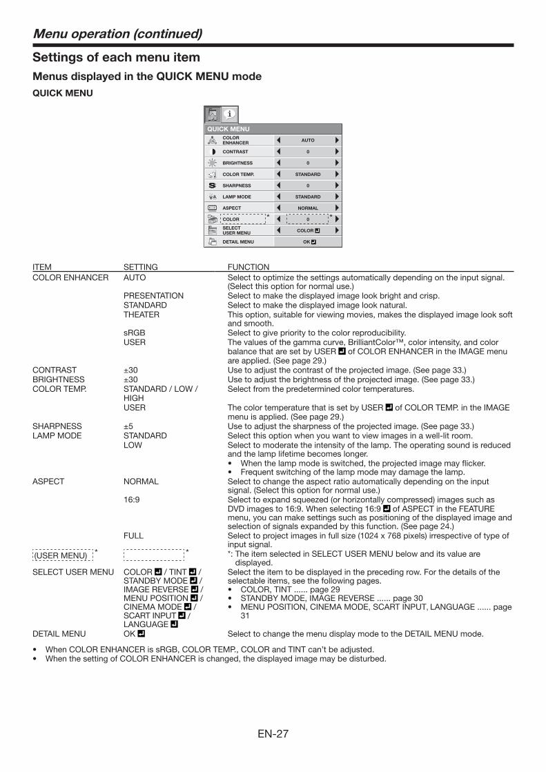
Settings of each menu itemMenus displayed in the QUICK MENU modeQUICK MENU
NORMALASPECT
LAMP MODE STANDARD
QUICK MENU
CONTRAST
BRIGHTNESS
0
0
STANDARD
COLOR
0COLOR
COLOR TEMP.
0SHARPNESS
AUTOCOLORENHANCER
SELECTUSER MENU
OKDETAIL MENU
* *
ITEM SETTING FUNCTIONCOLOR ENHANCER AUTO Select to optimize the settings automatically depending on the input signal.
(Select this option for normal use.)PRESENTATION Select to make the displayed image look bright and crisp.STANDARD Select to make the displayed image look natural.THEATER This option, suitable for viewing movies, makes the displayed image look soft
and smooth.sRGB Select to give priority to the color reproducibility.USER The values of the gamma curve, BrilliantColor™, color intensity, and color
balance that are set by USER of COLOR ENHANCER in the IMAGE menu are applied. (See page 29.)
CONTRAST ±30 Use to adjust the contrast of the projected image. (See page 33.)BRIGHTNESS ±30 Use to adjust the brightness of the projected image. (See page 33.)COLOR TEMP. STANDARD / LOW /
HIGHSelect from the predetermined color temperatures.
USER The color temperature that is set by USER of COLOR TEMP. in the IMAGE menu is applied. (See page 29.)
SHARPNESS ±5 Use to adjust the sharpness of the projected image. (See page 33.)LAMP MODE STANDARD Select this option when you want to view images in a well-lit room.
LOW Select to moderate the intensity of the lamp. The operating sound is reduced and the lamp lifetime becomes longer.• Whenthelampmodeisswitched,theprojectedimagemayflicker.• Frequentswitchingofthelampmodemaydamagethelamp.
ASPECT NORMAL Select to change the aspect ratio automatically depending on the input signal. (Select this option for normal use.)
16:9 Select to expand squeezed (or horizontally compressed) images such as DVD images to 16:9. When selecting 16:9 of ASPECT in the FEATURE menu, you can make settings such as positioning of the displayed image and selection of signals expanded by this function. (See page 24.)
FULL Select to project images in full size (1024 x 768 pixels) irrespective of type of input signal.
(USER MENU) * * *: The item selected in SELECT USER MENU below and its value are displayed.
SELECT USER MENU COLOR / TINT /STANDBY MODE /IMAGE REVERSE /MENU POSITION /CINEMA MODE /SCART INPUT /LANGUAGE
Select the item to be displayed in the preceding row. For the details of the selectable items, see the following pages.• COLOR,TINT......page29• STANDBYMODE,IMAGEREVERSE......page30• MENUPOSITION,CINEMAMODE,SCARTINPUT, LANGUAGE ...... page
31
DETAIL MENU OK Select to change the menu display mode to the DETAIL MENU mode.
• WhenCOLORENHANCERissRGB,COLORTEMP.,COLORandTINTcan’tbeadjusted.• WhenthesettingofCOLORENHANCERischanged,thedisplayedimagemaybedisturbed.
Menu operation (continued)
EN-28
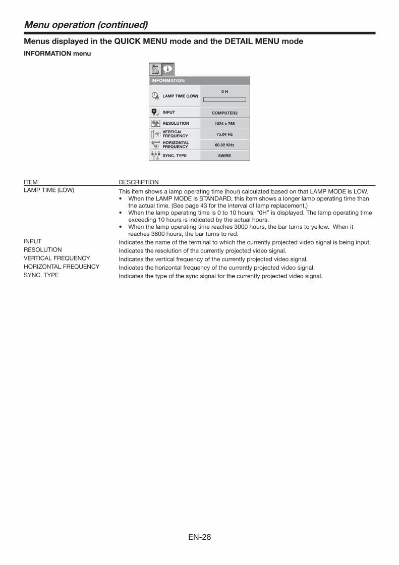
Menus displayed in the QUICK MENU mode and the DETAIL MENU modeINFORMATION menu
INFORMATION
LAMP TIME (LOW)
INPUT
RESOLUTION
VERTICALFREQUENCY
HORIZONTALFREQUENCY
SYNC. TYPE 5WIRE
60.02 KHz
75.04 Hz
1024 x 768
COMPUTER2
0 H
R G
H V
B
ITEM DESCRIPTIONLAMP TIME (LOW) This item shows a lamp operating time (hour) calculated based on that LAMP MODE is LOW.
• WhentheLAMPMODEisSTANDARD,thisitemshowsalongerlampoperatingtimethanthe actual time. (See page 43 for the interval of lamp replacement.)
• Whenthelampoperatingtimeis0to10hours,“0H”isdisplayed.Thelampoperatingtimeexceeding 10 hours is indicated by the actual hours.
• Whenthelampoperatingtimereaches3000hours,thebarturnstoyellow.Whenitreaches 3800 hours, the bar turns to red.
INPUT Indicates the name of the terminal to which the currently projected video signal is being input.RESOLUTION Indicates the resolution of the currently projected video signal. VERTICAL FREQUENCY Indicates the vertical frequency of the currently projected video signal. HORIZONTAL FREQUENCY Indicates the horizontal frequency of the currently projected video signal. SYNC. TYPE Indicates the type of the sync signal for the currently projected video signal.
Menu operation (continued)
EN-29
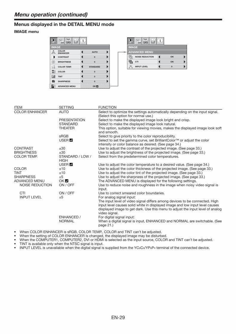
Menus displayed in the DETAIL MENU modeIMAGE menu
IMAGE
opt.
CONTRAST
BRIGHTNESS
0
0
STANDARD
0
0COLOR
TINT
COLOR TEMP.
0SHARPNESS
AUTOCOLORENHANCER
OKADVANCED MENU
IMAGE
ADVANCED MENU
opt.
ON
ON
NOISE REDUCTION
CTI
INPUT LEVEL 0
ITEM SETTING FUNCTIONCOLOR ENHANCER AUTO Select to optimize the settings automatically depending on the input signal.
(Select this option for normal use.)PRESENTATION Select to make the displayed image look bright and crisp.STANDARD Select to make the displayed image look natural.THEATER This option, suitable for viewing movies, makes the displayed image look soft
and smooth.sRGB Select to give priority to the color reproducibility.USER Select to set the gamma curve, set BrilliantColor™ or adjust the color
intensity or color balance as desired. (See page 34.)CONTRAST ±30 Use to adjust the contrast of the projected image. (See page 33.)BRIGHTNESS ±30 Use to adjust the brightness of the projected image. (See page 33.)COLOR TEMP. STANDARD / LOW /
HIGHSelect from the predetermined color temperatures.
USER Use to adjust the color temperature to a desired value. (See page 34.) COLOR ±10 Use to adjust the color thickness of the projected image. (See page 33.)TINT ±10 Use to adjust the color tint of the projected image. (See page 33.) SHARPNESS ±5 Use to adjust the sharpness of the projected image. (See page 33.)ADVANCED MENU OK The ADVANCED MENU is displayed for the following settings. NOISE REDUCTION ON / OFF Use to reduce noise and roughness in the image when noisy video signal is
input. CTI ON / OFF Use to correct smeared color boundaries. INPUT LEVEL ±5 For analog signal input:
The input level of video signal differs among devices to be connected. High input level causes solid white in displayed image and low input level causes displayed image to get dark. Use this menu to adjust the input level of analog video signal.
ENHANCED / NORMAL
For digital signal input: When a digital signal is input, ENHANCED and NORMAL are switchable. (See page 21.)
• WhenCOLORENHANCERissRGB,COLORTEMP.,COLORandTINTcan’tbeadjusted.• WhenthesettingofCOLORENHANCERischanged,thedisplayedimagemaybedisturbed.• WhentheCOMPUTER1,COMPUTER2,DVIorHDMIisselectedastheinputsource,COLORandTINTcan’tbeadjusted.• TINTisavailableonlywhentheNTSCsignalisinput.• INPUTLEVELisunavailablewhenthedigitalsignalissuppliedfromtheYCBCR/YPBPR terminal of the connected device.
Menu operation (continued)
EN-30
INSTALLATION menu
INSTALLATION
opt.
LAMP MODE
OFFAUTO POWER ON
STANDARD
STANDBY MODE STANDARD
ON SPLASH SCREEN ON
AUTO POWER OFF OFF
BACK COLOR BLUE
OFFIMAGE REVERSE
BLACKAV MUTE MODE
IMAGE CAPTURE GO
LENS LOCK OK
INSTALLATION
LENS LOCK
opt.
OFF
OFF
OK
ZOOM/FOCUS LOCK
LENS SHIFT LOCK
LENS SHIFT RESET
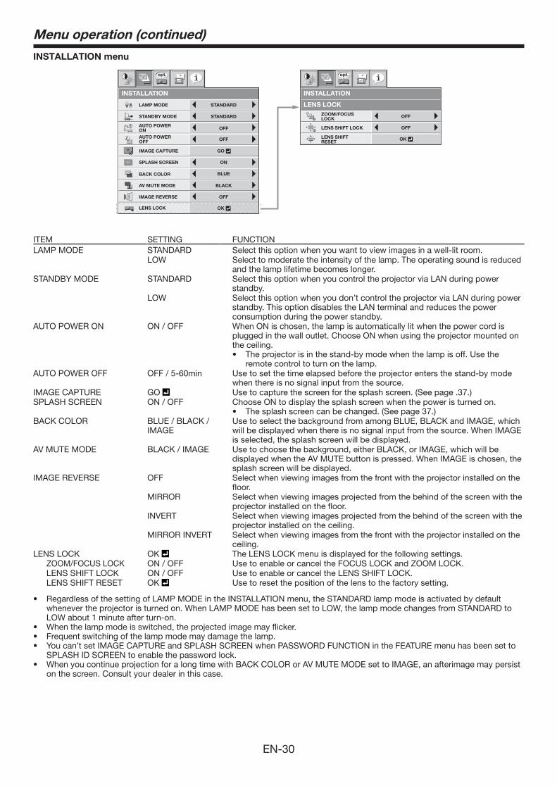
ITEM SETTING FUNCTIONLAMP MODE STANDARD Select this option when you want to view images in a well-lit room.
LOW Select to moderate the intensity of the lamp. The operating sound is reduced and the lamp lifetime becomes longer.
STANDBY MODE STANDARD Select this option when you control the projector via LAN during power standby.
LOW Select this option when you don’t control the projector via LAN during power standby. This option disables the LAN terminal and reduces the power consumption during the power standby.
AUTO POWER ON ON / OFF When ON is chosen, the lamp is automatically lit when the power cord is plugged in the wall outlet. Choose ON when using the projector mounted on the ceiling.• Theprojectorisinthestand-bymodewhenthelampisoff.Usethe
remote control to turn on the lamp. AUTO POWER OFF OFF / 5-60min Use to set the time elapsed before the projector enters the stand-by mode
when there is no signal input from the source. IMAGE CAPTURE GO Use to capture the screen for the splash screen. (See page .37.)SPLASH SCREEN ON / OFF Choose ON to display the splash screen when the power is turned on.
• Thesplashscreencanbechanged.(Seepage37.)BACK COLOR BLUE / BLACK /
IMAGEUse to select the background from among BLUE, BLACK and IMAGE, which will be displayed when there is no signal input from the source. When IMAGE is selected, the splash screen will be displayed.
AV MUTE MODE BLACK / IMAGE Use to choose the background, either BLACK, or IMAGE, which will be displayed when the AV MUTE button is pressed. When IMAGE is chosen, the splash screen will be displayed.
IMAGE REVERSE OFF Select when viewing images from the front with the projector installed on the floor.
MIRROR Select when viewing images projected from the behind of the screen with the projector installed on the floor.
INVERT Select when viewing images projected from the behind of the screen with the projector installed on the ceiling.
MIRROR INVERT Select when viewing images from the front with the projector installed on the ceiling.
LENS LOCK OK The LENS LOCK menu is displayed for the following settings. ZOOM/FOCUS LOCK ON / OFF Use to enable or cancel the FOCUS LOCK and ZOOM LOCK. LENS SHIFT LOCK ON / OFF Use to enable or cancel the LENS SHIFT LOCK. LENS SHIFT RESET OK Use to reset the position of the lens to the factory setting.
• RegardlessofthesettingofLAMPMODEintheINSTALLATIONmenu,theSTANDARDlampmodeisactivatedbydefaultwhenever the projector is turned on. When LAMP MODE has been set to LOW, the lamp mode changes from STANDARD to LOW about 1 minute after turn-on.
• Whenthelampmodeisswitched,theprojectedimagemayflicker.• Frequentswitchingofthelampmodemaydamagethelamp.• Youcan’tsetIMAGECAPTUREandSPLASHSCREENwhenPASSWORDFUNCTIONintheFEATUREmenuhasbeensetto
SPLASH ID SCREEN to enable the password lock.• WhenyoucontinueprojectionforalongtimewithBACKCOLORorAVMUTEMODEsettoIMAGE,anafterimagemaypersist
on the screen. Consult your dealer in this case.
Menu operation (continued)
EN-31
FEATURE menu
FEATURE
NORMAL
opt.
MENU POSITION
VIDEO SIGNAL?
ASPECT
RESET ALL
EnglishLANGUAGEA Ë
OK
SCART INPUT
DISPLAY INPUTPASSWORDFUNCTION
CINEMA MODE
1.
SETUP AUTO
OFF
AUTO
AUTO
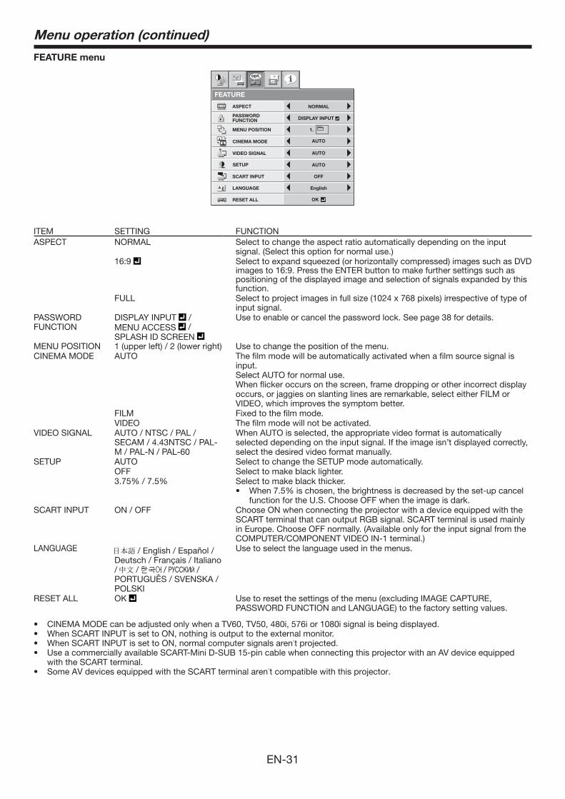
ITEM SETTING FUNCTIONASPECT NORMAL Select to change the aspect ratio automatically depending on the input
signal. (Select this option for normal use.) 16:9 Select to expand squeezed (or horizontally compressed) images such as DVD
images to 16:9. Press the ENTER button to make further settings such as positioning of the displayed image and selection of signals expanded by this function.
FULL Select to project images in full size (1024 x 768 pixels) irrespective of type of input signal.
PASSWORD FUNCTION
DISPLAY INPUT /MENU ACCESS / SPLASH ID SCREEN
Use to enable or cancel the password lock. See page 38 for details.
MENU POSITION 1 (upper left) / 2 (lower right) Use to change the position of the menu. CINEMA MODE AUTO The film mode will be automatically activated when a film source signal is
input.Select AUTO for normal use.When flicker occurs on the screen, frame dropping or other incorrect display occurs, or jaggies on slanting lines are remarkable, select either FILM or VIDEO, which improves the symptom better.
FILM Fixed to the film mode.VIDEO The film mode will not be activated.
VIDEO SIGNAL AUTO / NTSC / PAL / SECAM / 4.43NTSC / PAL-M / PAL-N / PAL-60
When AUTO is selected, the appropriate video format is automatically selected depending on the input signal. If the image isn’t displayed correctly, select the desired video format manually.
SETUP AUTO Select to change the SETUP mode automatically.OFF Select to make black lighter. 3.75%/7.5% Select to make black thicker.
• When7.5%ischosen,thebrightnessisdecreasedbytheset-upcancelfunction for the U.S. Choose OFF when the image is dark.
SCART INPUT ON / OFF Choose ON when connecting the projector with a device equipped with the SCART terminal that can output RGB signal. SCART terminal is used mainly in Europe. Choose OFF normally. (Available only for the input signal from the COMPUTER/COMPONENT VIDEO IN-1 terminal.)
LANGUAGE / English / Español / Deutsch / Français / Italiano / / / / PORTUGUÊS / SVENSKA / POLSKI
Use to select the language used in the menus.
RESET ALL OK Use to reset the settings of the menu (excluding IMAGE CAPTURE, PASSWORD FUNCTION and LANGUAGE) to the factory setting values.
• CINEMAMODEcanbeadjustedonlywhenaTV60,TV50,480i,576ior1080isignalisbeingdisplayed.• WhenSCARTINPUTissettoON,nothingisoutputtotheexternalmonitor.• WhenSCARTINPUTissettoON,normalcomputersignalsaren’t projected. • UseacommerciallyavailableSCART-MiniD-SUB15-pincablewhenconnectingthisprojectorwithanAVdeviceequipped
with the SCART terminal.• SomeAVdevicesequippedwiththeSCARTterminalaren’t compatible with this projector.
Menu operation (continued)
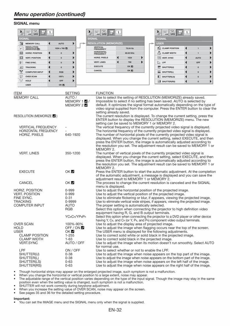
EN-32
SIGNAL menu
USER
1
CLAMP WIDTH
CLAMP POSITION
1
LPF OFF
SHUTTER(U) 0
SHUTTER(L) 0
VERT. SYNC AUTO?
SHUTTER(LS) 0
SHUTTER(RS) 0
SIGNAL
opt.
SIGNAL
VERTICAL FREQUENCYHORIZONTAL FREQUENCY
75.04 Hz
HORIZ. PIXELS 1024
60.02 KHz
CANCEL
opt.
OK
OKEXECUTE
768VERT. LINES
RESOLUTION (MEMORIZE)
R G BR G B
SIGNAL
HORIZ. POSITION 0
VERT. POSITION 0
TRACKING 0
COMPUTER INPUT RGB
FINE SYNC. 0
USER
opt.
OK
OFFHOLD
100%OVER SCAN
MEMORY CALL AUTO
RESOLUTION(MEMORIZE ) 1024 x 768V
H
AU
ITEM SETTING FUNCTIONMEMORY CALL AUTO /
MEMORY 1 / MEMORY 2
Use to select the setting of RESOLUTION (MEMORIZE) already saved. Impossible to select if no setting has been saved. AUTO is selected by default. It optimizes the signal format automatically depending on the type of video signal supplied from the computer. Press the ENTER button to clear the setting already saved.
RESOLUTION (MEMORIZE ) The current resolution is displayed. To change the current setting, press the ENTER button to display the RESOLUTION (MEMORIZE) menu. The new setting can be saved to MEMORY 1 or MEMORY 2.
VERTICAL FREQUENCY - The vertical frequency of the currently projected video signal is displayed. HORIZONTAL FREQUENCY - The horizontal frequency of the currently projected video signal is displayed. HORIZ. PIXELS 640-1920 The number of horizontal pixels of the currently projected video signal is
displayed. When you change the current setting, select EXECUTE, and then press the ENTER button, the image is automatically adjusted according to the resolution you set. The adjustment result can be saved to MEMORY 1 or MEMORY 2.
VERT. LINES 350-1200 The number of vertical pixels of the currently projected video signal is displayed. When you change the current setting, select EXECUTE, and then press the ENTER button, the image is automatically adjusted according to the resolution you set. The adjustment result can be saved to MEMORY 1 or MEMORY 2.
EXECUTE OK Press the ENTER button to start the automatic adjustment. At the completion of the automatic adjustment, a message is displayed and you can save the adjustment result to MEMORY 1 or MEMORY 2.
CANCEL OK The process to change the current resolution is canceled and the SIGNAL menu is displayed.
HORIZ. POSITION 0-999 Use to adjust the horizontal position of the projected image. VERT. POSITION 0-999 Use to adjust the vertical position of the projected image. FINE SYNC. 0-31 Use to eliminate flickering or blur, if appears, viewing the projected image. TRACKING 0-9999 Use to eliminate vertical wide stripes, if appears, viewing the projected image.COMPUTER INPUT AUTO The proper setting is automatically selected.
RGB Select this option when connecting the projector to high definition video equipment having R, G, and B output terminals.
YCBCR/YPBPR Select this option when connecting the projector to a DVD player or other device having Y, CB, and CR (or Y, PB, and PR) component video output terminals.
OVER SCAN 100%-90% Use to adjust the display area of projected image.HOLD OFF / ON Use to adjust the image when flagging occurs near the top of the screen.USER OK The USER menu is displayed for the following adjustments. CLAMP POSITION 1-255 Use to correct solid white or solid black in the projected image. CLAMP WIDTH 1-63 Use to correct solid black in the projected image. VERT.SYNC AUTO / OFF Use to adjust the image when its motion doesn’t run smoothly. Select AUTO
for normal use. LPF ON / OFF Use to select whether or not to enable the LPF. SHUTTER(U) 0-38 Use to adjust the image when noise appears on the top part of the image. SHUTTER(L) 0-38 Use to adjust the image when noise appears on the bottom part of the image. SHUTTER(LS) 0-63 Use to adjust the image when noise appears on the left half of the image. SHUTTER(RS) 0-63 Use to adjust the image when noise appears on the right half of the image.
• Thoughhorizontalstripsmayappearontheenlargedprojectedimage,suchsymptomisnotamalfunction.• Whenyouchangethehorizontalorverticalpositiontoalargeextent,noisemayappear.• Theadjustablerangeoftheverticalpositionvariesdependingonthetypeoftheinputsignal.Thoughtheimagemaystayinthesame
position even when the setting value is changed, such symptom is not a malfunction.• SHUTTERwillnotworkcorrectlyduringkeystoneadjustment.• WhenyouincreasethesettingvalueofOVERSCAN,noisemayappearonthescreen.• Seepages35and36forthedetailedsettingprocedure.
Important:• YoucansettheIMAGEmenuandtheSIGNALmenuonlywhenthesignalissupplied.
Menu operation (continued)
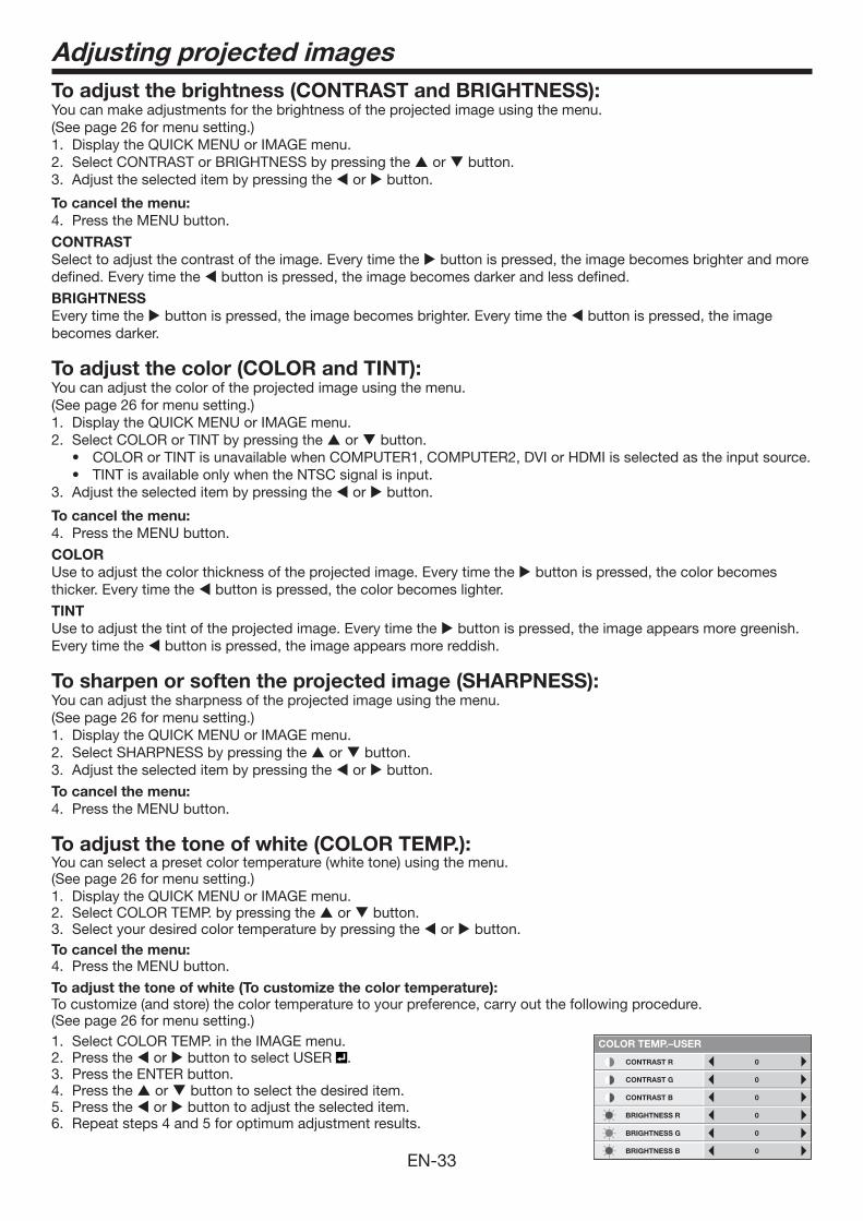
EN-33
Adjusting projected imagesTo adjust the brightness (CONTRAST and BRIGHTNESS):You can make adjustments for the brightness of the projected image using the menu. (See page 26 for menu setting.) 1. Display the QUICK MENU or IMAGE menu. 2. Select CONTRAST or BRIGHTNESS by pressing the or button. 3. Adjust the selected item by pressing the or button.
To cancel the menu:4. Press the MENU button.
CONTRAST Select to adjust the contrast of the image. Every time the button is pressed, the image becomes brighter and more defined. Every time the button is pressed, the image becomes darker and less defined.
BRIGHTNESSEvery time the button is pressed, the image becomes brighter. Every time the button is pressed, the image becomes darker.
To adjust the color (COLOR and TINT):You can adjust the color of the projected image using the menu. (See page 26 for menu setting.) 1. Display the QUICK MENU or IMAGE menu. 2. Select COLOR or TINT by pressing the or button.
• COLORorTINTisunavailablewhenCOMPUTER1,COMPUTER2,DVIorHDMIisselectedastheinputsource.• TINTisavailableonlywhentheNTSCsignalisinput.
3. Adjust the selected item by pressing the or button.
To cancel the menu:4. Press the MENU button.
COLOR Use to adjust the color thickness of the projected image. Every time the button is pressed, the color becomes thicker. Every time the button is pressed, the color becomes lighter.
TINTUse to adjust the tint of the projected image. Every time the button is pressed, the image appears more greenish.Every time the button is pressed, the image appears more reddish.
To sharpen or soften the projected image (SHARPNESS):You can adjust the sharpness of the projected image using the menu. (See page 26 for menu setting.) 1. Display the QUICK MENU or IMAGE menu. 2. Select SHARPNESS by pressing the or button. 3. Adjust the selected item by pressing the or button.
To cancel the menu:4. Press the MENU button.
To adjust the tone of white (COLOR TEMP.): You can select a preset color temperature (white tone) using the menu. (See page 26 for menu setting.) 1. Display the QUICK MENU or IMAGE menu. 2. Select COLOR TEMP. by pressing the or button. 3. Select your desired color temperature by pressing the or button. To cancel the menu:4. Press the MENU button.
To adjust the tone of white (To customize the color temperature): To customize (and store) the color temperature to your preference, carry out the following procedure. (See page 26 for menu setting.) 1. Select COLOR TEMP. in the IMAGE menu. 2. Press the or button to select USER . 3. Press the ENTER button.4. Press the or button to select the desired item. 5. Press the or button to adjust the selected item. 6. Repeat steps 4 and 5 for optimum adjustment results.
CONTRAST B 0
BRIGHTNESS R 0
CONTRAST R
COLOR TEMP.–USER
0
CONTRAST G 0
BRIGHTNESS G 0
BRIGHTNESS B 0
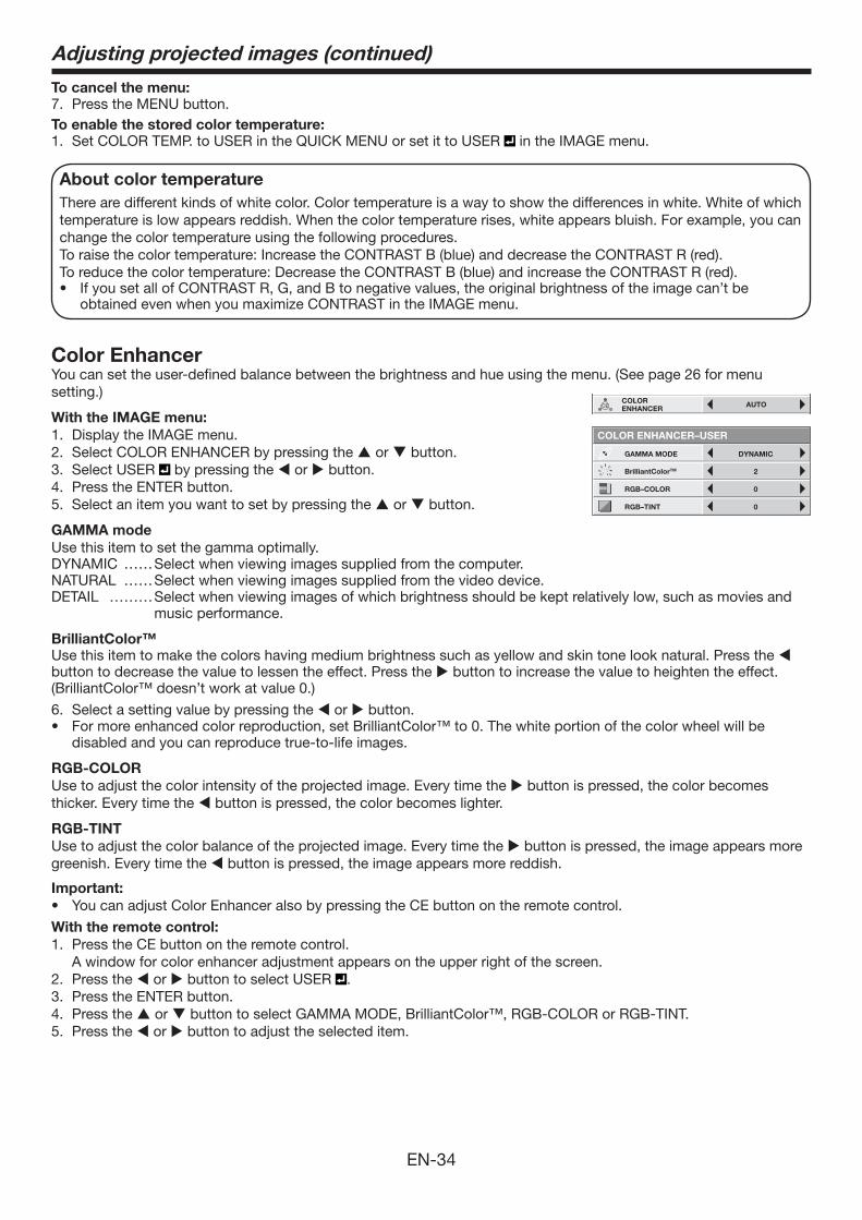
EN-34
To cancel the menu:7. Press the MENU button. To enable the stored color temperature: 1. Set COLOR TEMP. to USER in the QUICK MENU or set it to USER in the IMAGE menu.
About color temperatureThere are different kinds of white color. Color temperature is a way to show the differences in white. White of which temperature is low appears reddish. When the color temperature rises, white appears bluish. For example, you can change the color temperature using the following procedures. To raise the color temperature: Increase the CONTRAST B (blue) and decrease the CONTRAST R (red).To reduce the color temperature: Decrease the CONTRAST B (blue) and increase the CONTRAST R (red).• IfyousetallofCONTRASTR,G,andBtonegativevalues,theoriginalbrightnessoftheimagecan’tbe
obtained even when you maximize CONTRAST in the IMAGE menu.
Color EnhancerYou can set the user-defined balance between the brightness and hue using the menu. (See page 26 for menu setting.)
With the IMAGE menu:1. Display the IMAGE menu.2. Select COLOR ENHANCER by pressing the or button.3. Select USER by pressing the or button.4. Press the ENTER button.5. Select an item you want to set by pressing the or button.
GAMMA modeUse this item to set the gamma optimally.DYNAMIC ��Select when viewing images supplied from the computer.NATURAL ��Select when viewing images supplied from the video device.DETAIL ���Select when viewing images of which brightness should be kept relatively low, such as movies and
music performance.
BrilliantColor™Use this item to make the colors having medium brightness such as yellow and skin tone look natural. Press the button to decrease the value to lessen the effect. Press the button to increase the value to heighten the effect.(BrilliantColor™ doesn’t work at value 0.)
6. Select a setting value by pressing the or button. • Formoreenhancedcolorreproduction,setBrilliantColor™to0.Thewhiteportionofthecolorwheelwillbe
disabled and you can reproduce true-to-life images.
RGB-COLOR Use to adjust the color intensity of the projected image. Every time the button is pressed, the color becomes thicker. Every time the button is pressed, the color becomes lighter.
RGB-TINTUse to adjust the color balance of the projected image. Every time the button is pressed, the image appears more greenish. Every time the button is pressed, the image appears more reddish.
Important:• You can adjust Color Enhancer also by pressing the CE button on the remote control.
With the remote control:1. Press the CE button on the remote control. A window for color enhancer adjustment appears on the upper right of the screen. 2. Press the or button to select USER .3. Press the ENTER button.4. Press the or button to select GAMMA MODE, BrilliantColor™, RGB-COLOR or RGB-TINT. 5. Press the or button to adjust the selected item.
IMAGE
opt.
CONTRAST
BRIGHTNESS
0
0
STANDARD
0
0COLOR
TINT
COLOR TEMP.
0SHARPNESS
AUTOCOLORENHANCER
OKADVANCED MENU
RGB–TINT 0
GAMMA MODE DYNAMIC
COLOR ENHANCER–USER
RGB–COLOR 0
BrilliantColorTM 2
Adjusting projected images (continued)
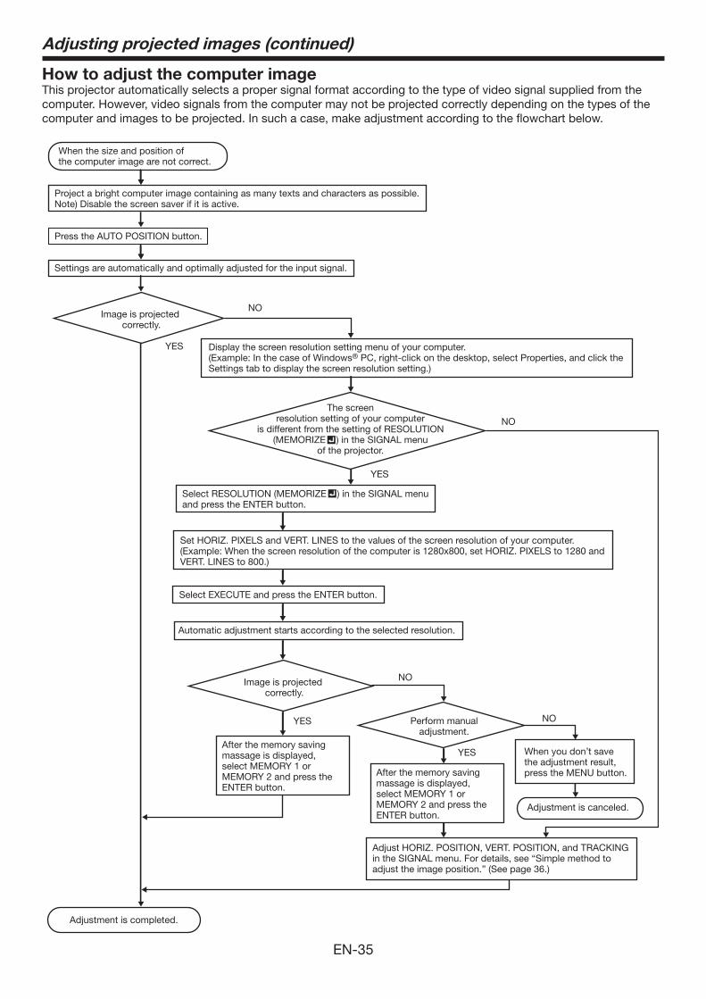
EN-35
Adjusting projected images (continued)
How to adjust the computer imageThis projector automatically selects a proper signal format according to the type of video signal supplied from the computer. However, video signals from the computer may not be projected correctly depending on the types of the computer and images to be projected. In such a case, make adjustment according to the flowchart below.
Adjustment is completed.
When the size and position of the computer image are not correct.
Project a bright computer image containing as many texts and characters as possible.Note) Disable the screen saver if it is active.
Press the AUTO POSITION button.
Settings are automatically and optimally adjusted for the input signal.
Image is projected correctly.
YES
NO
Display the screen resolution setting menu of your computer. (Example: In the case of Windows® PC, right-click on the desktop, select Properties, and click the Settings tab to display the screen resolution setting.)
The screen resolution setting of your computer
is different from the setting of RESOLUTION (MEMORIZE ) in the SIGNAL menu
of the projector.
Select RESOLUTION (MEMORIZE ) in the SIGNAL menu and press the ENTER button.
Set HORIZ. PIXELS and VERT. LINES to the values of the screen resolution of your computer. (Example: When the screen resolution of the computer is 1280x800, set HORIZ. PIXELS to 1280 and VERT. LINES to 800.)
Select EXECUTE and press the ENTER button.
Automatic adjustment starts according to the selected resolution.
Image is projected correctly.
Perform manual adjustment.
After the memory saving massage is displayed, select MEMORY 1 or MEMORY 2 and press the ENTER button.
After the memory saving massage is displayed, select MEMORY 1 or MEMORY 2 and press the ENTER button.
When you don’t save the adjustment result, press the MENU button.
Adjustment is canceled.
Adjust HORIZ. POSITION, VERT. POSITION, and TRACKING in the SIGNAL menu. For details, see “Simple method to adjust the image position.” (See page 36.)
YES
NO
YES
NO
YES
NO
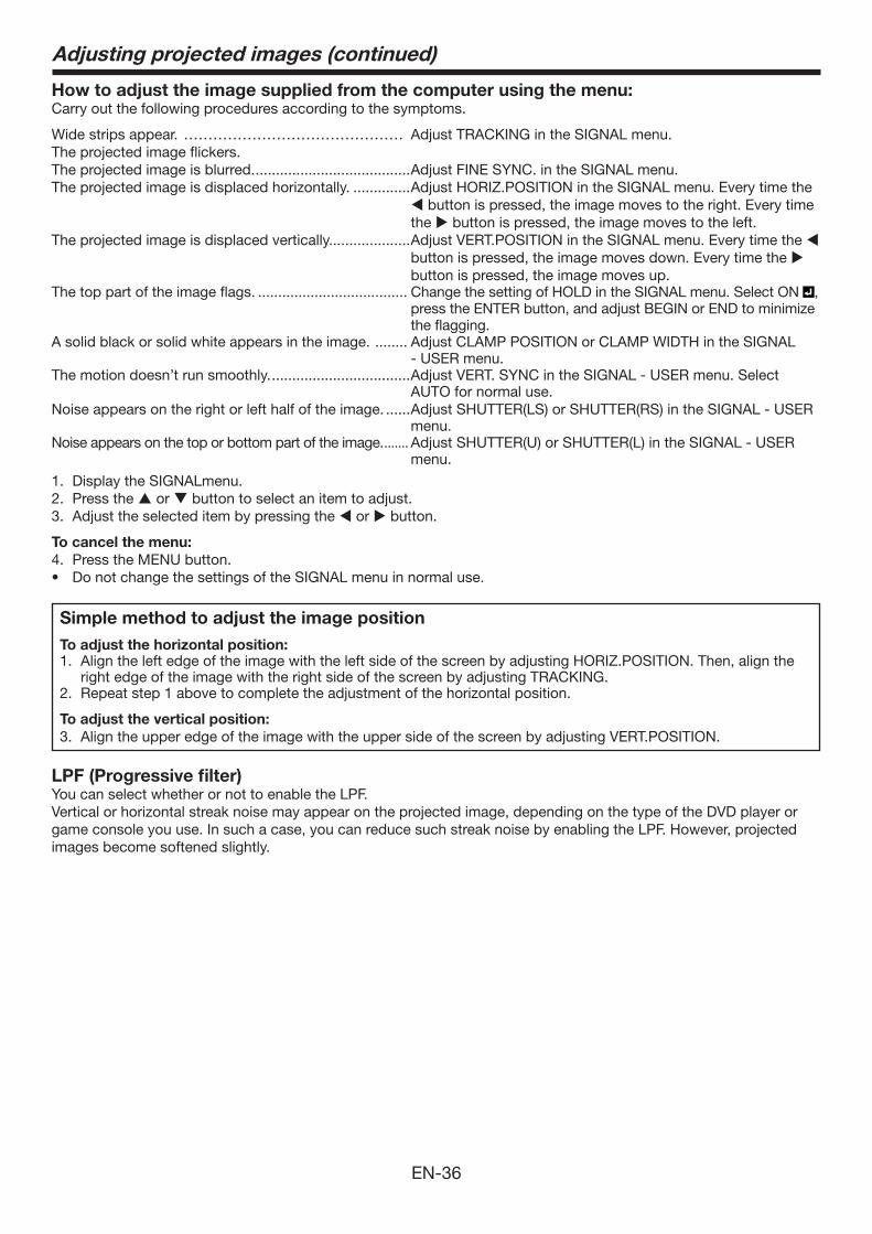
EN-36
How to adjust the image supplied from the computer using the menu:Carry out the following procedures according to the symptoms.
Wide strips appear. ��������������� Adjust TRACKING in the SIGNAL menu. The projected image flickers. The projected image is blurred. ......................................Adjust FINE SYNC. in the SIGNAL menu. The projected image is displaced horizontally. ..............Adjust HORIZ.POSITION in the SIGNAL menu. Every time the
button is pressed, the image moves to the right. Every time the button is pressed, the image moves to the left.
The projected image is displaced vertically....................Adjust VERT.POSITION in the SIGNAL menu. Every time the button is pressed, the image moves down. Every time the button is pressed, the image moves up.
The top part of the image flags. ..................................... Change the setting of HOLD in the SIGNAL menu. Select ON , press the ENTER button, and adjust BEGIN or END to minimize the flagging.
A solid black or solid white appears in the image. ........ Adjust CLAMP POSITION or CLAMP WIDTH in the SIGNAL - USER menu.
The motion doesn’t run smoothly. ..................................Adjust VERT. SYNC in the SIGNAL - USER menu. Select AUTO for normal use.
Noise appears on the right or left half of the image. ......Adjust SHUTTER(LS) or SHUTTER(RS) in the SIGNAL - USER menu.
Noise appears on the top or bottom part of the image. ....... Adjust SHUTTER(U) or SHUTTER(L) in the SIGNAL - USER menu.
1. Display the SIGNALmenu. 2. Press the or button to select an item to adjust. 3. Adjust the selected item by pressing the or button.
To cancel the menu:4. Press the MENU button. • DonotchangethesettingsoftheSIGNALmenuinnormaluse.
Simple method to adjust the image positionTo adjust the horizontal position: 1. Align the left edge of the image with the left side of the screen by adjusting HORIZ.POSITION. Then, align the
right edge of the image with the right side of the screen by adjusting TRACKING. 2. Repeat step 1 above to complete the adjustment of the horizontal position.
To adjust the vertical position: 3. Align the upper edge of the image with the upper side of the screen by adjusting VERT.POSITION.
LPF (Progressive filter) You can select whether or not to enable the LPF. Vertical or horizontal streak noise may appear on the projected image, depending on the type of the DVD player or game console you use. In such a case, you can reduce such streak noise by enabling the LPF. However, projected images become softened slightly.
Adjusting projected images (continued)
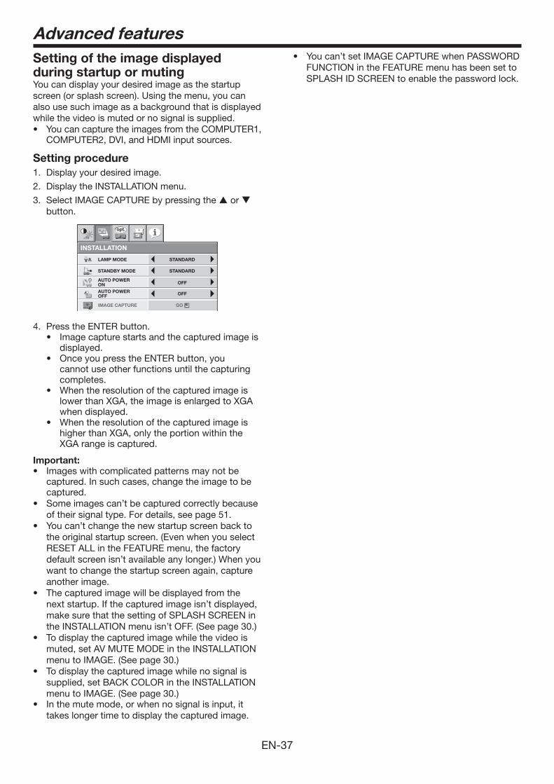
EN-37
Setting of the image displayed during startup or mutingYou can display your desired image as the startup screen (or splash screen). Using the menu, you can also use such image as a background that is displayed while the video is muted or no signal is supplied.• Youcancapture the images from the COMPUTER1,
COMPUTER2, DVI, and HDMI input sources.
Setting procedure 1. Display your desired image.
2. Display the INSTALLATION menu.
3. Select IMAGE CAPTURE by pressing the or button.
INSTALLATION
opt.
LAMP MODE
OFFAUTO POWER ON
STANDARD
STANDBY MODE STANDARD
ON SPLASH SCREEN ON
AUTO POWER OFF OFF
BACK COLOR BLUE
OFFIMAGE REVERSE
BLACKAV MUTE MODE
IMAGE CAPTURE GO
LENS LOCK OK
4. Press the ENTER button.• Imagecapturestartsandthecapturedimageis
displayed. • OnceyoupresstheENTERbutton,you
cannot use other functions until the capturing completes.
• Whentheresolutionofthecapturedimageislower than XGA, the image is enlarged to XGA when displayed.
• Whentheresolutionofthecapturedimageishigher than XGA, only the portion within the XGA range is captured.
Important:• Imageswithcomplicatedpatternsmaynotbe
captured. In such cases, change the image to be captured.
• Some images can’t be captured correctly because of their signal type. For details, see page 51.
• You can’t change the new startup screen back to the original startup screen. (Even when you select RESET ALL in the FEATURE menu, the factory default screen isn’t available any longer.) When you want to change the startup screen again, capture another image.
• The captured image will be displayed from the next startup. If the captured image isn’t displayed, make sure that the setting of SPLASH SCREEN in the INSTALLATION menu isn’t OFF. (See page 30.)
• To display the captured image while the video is muted, set AV MUTE MODE in the INSTALLATION menu to IMAGE. (See page 30.)
• To display the captured image while no signal is supplied, set BACK COLOR in the INSTALLATION menu to IMAGE. (See page 30.)
• Inthemutemode,orwhennosignalisinput,ittakes longer time to display the captured image.
Advanced features• Youcan’tsetIMAGECAPTUREwhenPASSWORD
FUNCTION in the FEATURE menu has been set to SPLASH ID SCREEN to enable the password lock.
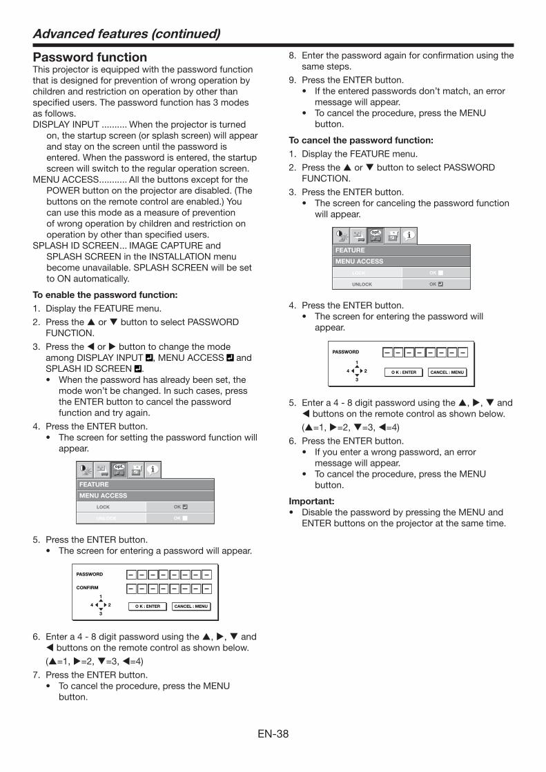
EN-38
Password functionThis projector is equipped with the password function that is designed for prevention of wrong operation by children and restriction on operation by other than specified users. The password function has 3 modes as follows.DISPLAY INPUT .......... When the projector is turned
on, the startup screen (or splash screen) will appear and stay on the screen until the password is entered. When the password is entered, the startup screen will switch to the regular operation screen.
MENU ACCESS ........... All the buttons except for the POWER button on the projector are disabled. (The buttons on the remote control are enabled.) You can use this mode as a measure of prevention of wrong operation by children and restriction on operation by other than specified users.
SPLASH ID SCREEN ... IMAGE CAPTURE and SPLASH SCREEN in the INSTALLATION menu become unavailable. SPLASH SCREEN will be set to ON automatically.
To enable the password function:1. Display the FEATURE menu.
2. Press the or button to select PASSWORD FUNCTION.
3. Press the or button to change the mode among DISPLAY INPUT , MENU ACCESS and SPLASH ID SCREEN .• When the password has already been set, the
mode won’t be changed. In such cases, press the ENTER button to cancel the password function and try again.
4. Press the ENTER button.• The screen for setting the password function will
appear.
MENU ACCESS
FEATURE
opt.
LOCK
UNLOCK
OK
OK
5. Press the ENTER button.• The screen for entering a password will appear.
PASSWORD
CONFIRM
1
3
24 O K : ENTER CANCEL : MENU
6. Enter a 4 - 8 digit password using the , , and buttons on the remote control as shown below.
(=1, =2, =3, =4)
7. Press the ENTER button.• To cancel the procedure, press the MENU
button.
Advanced features (continued)
8. Enter the password again for confirmation using the same steps.
9. Press the ENTER button. • If the entered passwords don’t match, an error
message will appear. • To cancel the procedure, press the MENU
button.
To cancel the password function: 1. Display the FEATURE menu.
2. Press the or button to select PASSWORD FUNCTION.
3. Press the ENTER button.• The screen for canceling the password function
will appear.
MENU ACCESS
FEATURE
opt.
LOCK
UNLOCK
OK
OK
4. Press the ENTER button.• The screen for entering the password will
appear.
PASSWORD
1
3
24 O K : ENTER CANCEL : MENU
5. Enter a 4 - 8 digit password using the , , and buttons on the remote control as shown below.
(=1, =2, =3, =4)
6. Press the ENTER button.• If you enter a wrong password, an error
message will appear.• To cancel the procedure, press the MENU
button.
Important:• Disable the password by pressing the MENU and
ENTER buttons on the projector at the same time.
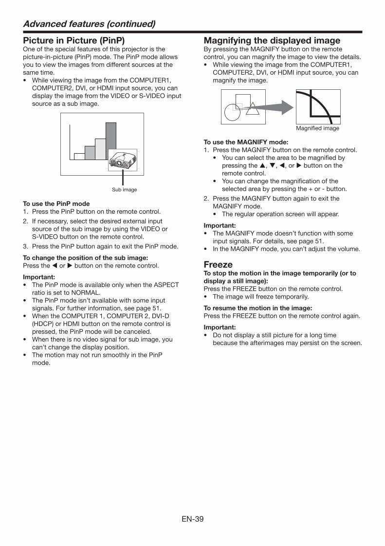
EN-39
Picture in Picture (PinP) One of the special features of this projector is the picture-in-picture (PinP) mode. The PinP mode allows you to view the images from different sources at the same time. • WhileviewingtheimagefromtheCOMPUTER1,
COMPUTER2, DVI, or HDMI input source, you can display the image from the VIDEO or S-VIDEO input source as a sub image.
Sub image
To use the PinP mode1. Press the PinP button on the remote control.
2. If necessary, select the desired external input source of the sub image by using the VIDEO or S-VIDEO button on the remote control.
3. Press the PinP button again to exit the PinP mode.
To change the position of the sub image:Press the or button on the remote control.
Important:• ThePinPmodeisavailableonlywhentheASPECT
ratio is set to NORMAL. • The PinP mode isn’t available with some input
signals. For further information, see page 51. • When the COMPUTER 1, COMPUTER 2, DVI-D
(HDCP) or HDMI button on the remote control is pressed, the PinP mode will be canceled.
• Whenthereisnovideosignalforsubimage,youcan’t change the display position.
• The motion may not run smoothly in the PinP mode.
Advanced features (continued)
Magnifying the displayed imageBy pressing the MAGNIFY button on the remote control, you can magnify the image to view the details.• WhileviewingtheimagefromtheCOMPUTER1,
COMPUTER2, DVI, or HDMI input source, you can magnify the image.
Magnified image
To use the MAGNIFY mode:1. Press the MAGNIFY button on the remote control.
• You can select the area to be magnified by pressing the , , , or button on the remote control.
• You can change the magnification of the selectedareabypressingthe+or-button.
2. Press the MAGNIFY button again to exit the MAGNIFY mode.• The regular operation screen will appear.
Important:• The MAGNIFY mode doesn’t function with some
input signals. For details, see page 51.• In the MAGNIFY mode, you can’t adjust the volume.
FreezeTo stop the motion in the image temporarily (or to display a still image):Press the FREEZE button on the remote control.• The image will freeze temporarily.
To resume the motion in the image:Press the FREEZE button on the remote control again.
Important:• Donotdisplayastillpictureforalongtime
because the afterimages may persist on the screen.
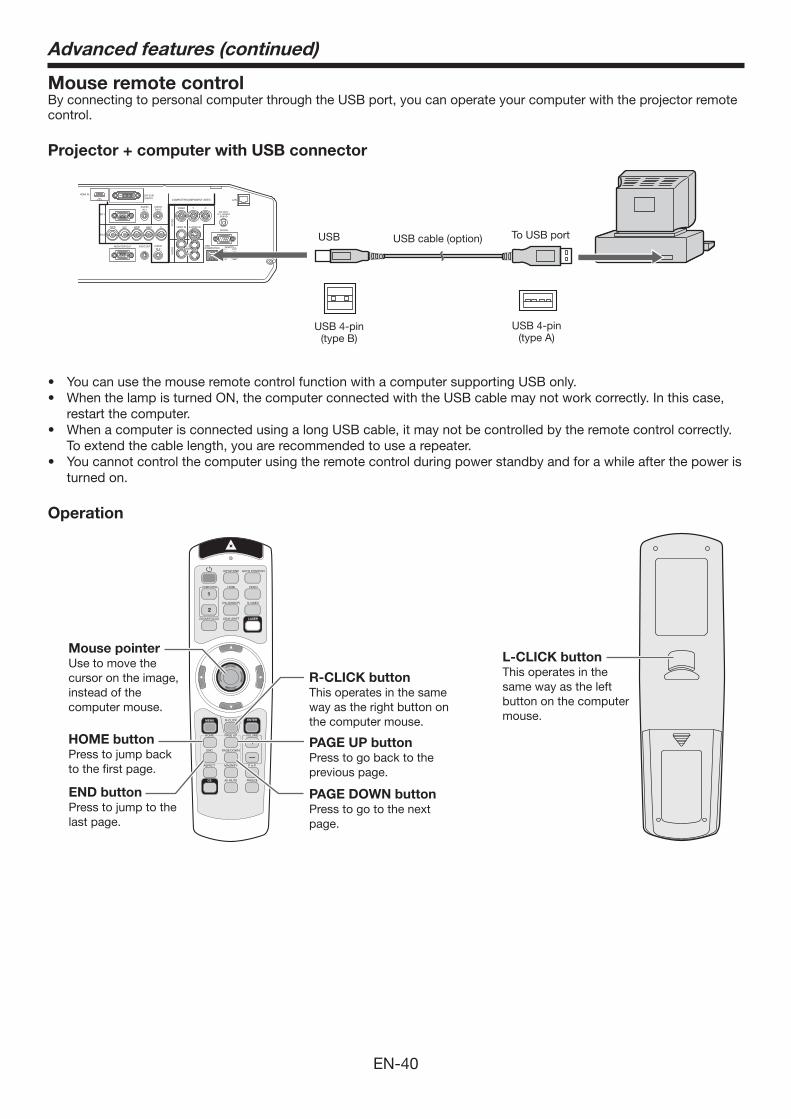
EN-40
Mouse remote controlBy connecting to personal computer through the USB port, you can operate your computer with the projector remote control.
Projector + computer with USB connector
USB cable (option)
USB 4-pin(type B)
USB 4-pin(type A)
To USB portUSB
• Youcanuse the mouse remote control function with a computer supporting USB only. • WhenthelampisturnedON,thecomputerconnectedwiththeUSBcablemaynotworkcorrectly.Inthiscase,
restart the computer.• WhenacomputerisconnectedusingalongUSBcable,itmaynotbecontrolledbytheremotecontrolcorrectly.
To extend the cable length, you are recommended to use a repeater.• Youcannotcontrolthecomputerusingtheremotecontrolduringpowerstandbyandforawhileafterthepoweris
turned on.
Operation
COMPUTER HDMI VIDEO
KEYSTONE AUTO POSITION
DVI-D(HDCP) S-VIDEO
FREEZE
MAGNIFY
AV MUTE
PAGE UPHOME
PAGE DOWNEND
1
2
P in P
VOLUME
CE
ASPECT
MENU ENTER
ZOOM/FOCUS LENS SHIFT LASER
R-CLICK
Mouse pointerUse to move the cursor on the image, instead of the computer mouse.
R-CLICK buttonThis operates in the same way as the right button on the computer mouse.
L-CLICK buttonThis operates in the same way as the left button on the computer mouse.
HOME buttonPress to jump back to the first page.
END buttonPress to jump to the last page.
PAGE UP buttonPress to go back to the previous page.
PAGE DOWN buttonPress to go to the next page.
Advanced features (continued)
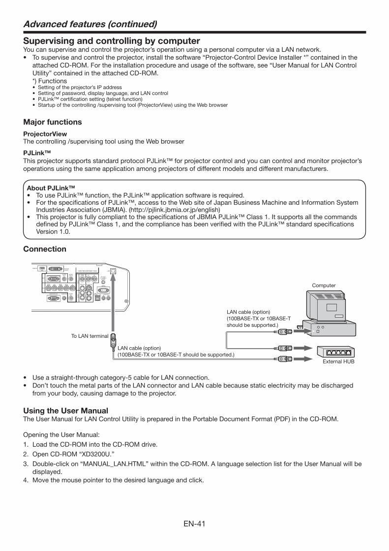
EN-41
Supervising and controlling by computerYou can supervise and control the projector’s operation using a personal computer via a LAN network. • Tosuperviseandcontroltheprojector,installthesoftware“Projector-ControlDeviceInstaller*”containedinthe
attached CD-ROM. For the installation procedure and usage of the software, see “User Manual for LAN Control Utility” contained in the attached CD-ROM.
*) Functions• Settingoftheprojector’sIPaddress• Settingofpassword,displaylanguage,andLANcontrol• PJLink™certificationsetting(telnetfunction)• Startupofthecontrolling/supervisingtool(ProjectorView)usingtheWebbrowser
Major functionsProjectorViewThe controlling /supervising tool using the Web browser
PJLink™This projector supports standard protocol PJLink™ for projector control and you can control and monitor projector’s operations using the same application among projectors of different models and different manufacturers.
About PJLink™• TousePJLink™function,thePJLink™applicationsoftwareisrequired.• ForthespecificationsofPJLink™,accesstotheWebsiteofJapanBusinessMachineandInformationSystem
Industries Association (JBMIA). (http://pjlink.jbmia.or.jp/english)• ThisprojectorisfullycomplianttothespecificationsofJBMIAPJLink™Class1.Itsupportsallthecommands
defined by PJLink™ Class 1, and the compliance has been verified with the PJLink™ standard specifications Version 1.0.
Connection
Computer
To LAN terminal
LAN cable (option)(100BASE-TX or 10BASE-T should be supported.)
LAN cable (option)(100BASE-TX or 10BASE-T should be supported.)
External HUB
• Useastraight-throughcategory-5cableforLANconnection.• Don’ttouchthemetalpartsoftheLANconnectorandLANcablebecausestaticelectricitymaybedischarged
from your body, causing damage to the projector.
Using the User ManualThe User Manual for LAN Control Utility is prepared in the Portable Document Format (PDF) in the CD-ROM.
Opening the User Manual:
1. Load the CD-ROM into the CD-ROM drive.
2. Open CD-ROM “XD3200U.”
3. Double-click on “MANUAL_LAN.HTML” within the CD-ROM. A language selection list for the User Manual will be displayed.
4. Move the mouse pointer to the desired language and click.
Advanced features (continued)
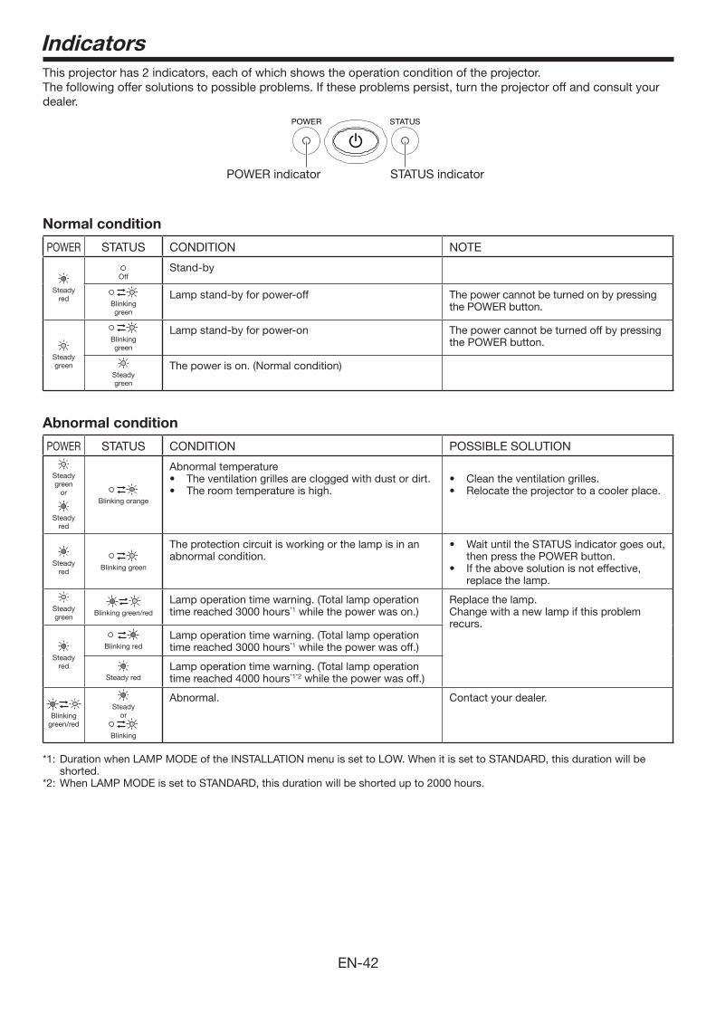
EN-42
IndicatorsThis projector has 2 indicators, each of which shows the operation condition of the projector. The following offer solutions to possible problems. If these problems persist, turn the projector off and consult your dealer.
POWER indicator STATUS indicator
Normal condition
POWER STATUS CONDITION NOTE
Steadyred
OffStand-by
Blinkinggreen
Lamp stand-by for power-off The power cannot be turned on by pressing the POWER button.
Steadygreen
Blinkinggreen
Lamp stand-by for power-on The power cannot be turned off by pressing the POWER button.
Steadygreen
The power is on. (Normal condition)
Abnormal condition
POWER STATUS CONDITION POSSIBLE SOLUTION
Steady green
or
Steady red
Blinking orange
Abnormal temperature• Theventilationgrillesarecloggedwithdustordirt.• Theroomtemperatureishigh.
• Cleantheventilationgrilles.• Relocatetheprojectortoacoolerplace.
Steady red
Blinking green
The protection circuit is working or the lamp is in an abnormal condition.
• WaituntiltheSTATUSindicatorgoesout,then press the POWER button.
• Iftheabovesolutionisnoteffective,replace the lamp.
Steady green
Blinking green/red
Lamp operation time warning. (Total lamp operation time reached 3000 hours*1 while the power was on.)
Replace the lamp.Change with a new lamp if this problem recurs.
Steady red
Blinking redLamp operation time warning. (Total lamp operation time reached 3000 hours*1 while the power was off.)
Steady redLamp operation time warning. (Total lamp operation time reached 4000 hours*1*2 while the power was off.)
Blinking green/red
Steady or
Blinking
Abnormal. Contact your dealer.
*1: Duration when LAMP MODE of the INSTALLATION menu is set to LOW. When it is set to STANDARD, this duration will be shorted.
*2: When LAMP MODE is set to STANDARD, this duration will be shorted up to 2000 hours.

EN-43
Replacing the lampThis projector is equipped with a lamp to project images. This lamp is a consumable. It may burn out or its brightness may decrease during use. In such cases, replace the lamp with a new one as soon as possible. Be sure to replace the lamp with a new lamp separately sold that is exclusive to this projector. Contact your dealer for purchase of the lamp.
Spare lamp VLT-XD3200LP
Warning:• Becarefulnottodropthelampfixingscrewsintotheinsideoftheprojector.Don’tputametalpieceorflammable
object into the projector. Using the projector with any foreign object present inside may result in electric shock or fire. When you can’t remove the foreign object from the inside, contact your dealer for removal.
• Besuretoinstallthelampsecurely.Whenthelampisn’tinstalledproperly,itwon’tilluminate.Improperinstallationmay also result in fire.
• Don’tshaketheremovedlampordon’tliftitaboveyourface.Youmaybeinjuredinyoureyebyflyingorfallingglass fragments.
• Don’treplacethelampimmediatelyafterusebecausethelampcoverisveryhot.Youmaygetburned.Turnoffthepower using the POWER button. After the lamp goes out, wait about 2 minutes until the intake and exhaust fans for cooling the lamp stop rotating. Then turn off the main power switch, unplug the power cord, and wait at least 1 hour to allow the lamp to cool down enough to the touch.
• Do not touch the lamp directly. It may break and cause injury or burn.
Interval of lamp replacementThe recommended interval of lamp replacement is about 4000 hours*1*2 of consecutive use. Such interval differs depending on the operating environment and may be shorter than 4000 hours*1*2. Decrease in luminescence and/or color brightness indicates that the lamp needs to be replaced. When the lamp operation time exceeds 3000 hours*1, the indicator will blink alternately between green and red (while the lamp is lit; when the lamp is not lit, the indicator will be lit red only) and the lamp replacement message will appear on the screen for 1 minute everytime the lamp is turned on. When the lamp has been used for about 3800 hours*1, the replacement message (LAMP EXCHANGE) will appear on the screen for 1 minute every 20 hours*1 thereafter. When the lamp operation time exceeds 4000 hours*1*2, the projector automatically shuts off and can’t be used until the lamp is replaced and the lamp operation time is reset.*1: Duration when LAMP MODE of the INSTALLATION menu is set to LOW. When it is set to STANDARD, this duration will be
shorted.*2: When LAMP MODE is set to STANDARD, this duration will be shorted to 2000 hours.
Caution:• Don’tremovethelampforanypurposeotherthanreplacement.Unnecessaryremovalofthelampmayresultina
breakdown.• Thisprojectorusesahigh-pressuremercurylampasthelightsource.Thehigh-pressuremercurylampmay
explode or fail to illuminate permanently because of an impact, scratch, or deterioration through use. The period of time until explosion or permanent failure to illuminate varies considerably from lamp to lamp, depending on operation conditions. Therefore, the lamp may explode soon after the start of use.
• Thepossibilityofexplosionofthelampincreasesifyouuseitbeyonditsreplacementperiod.Whentheinstructionof lamp replacement appears, replace it with a new one immediately even if the lamp is still lighting normally.
• Whenthehigh-pressuremercurylampexplodes,glassfragmentswillscatterinsideoroutsidethelampboxandthe gas charged inside the lamp will diffuse inside or outside the projector. The gas inside the lamp contains mercury. Be careful not to breathe it or avoid it from entering your eye or mouth. If you should breathe it or if it should enter your eye or mouth, see a doctor immediately.
• Intheeventthatthehigh-pressuremercurylampexploded,glassfragmentsmayhavebeenscatteredinsidetheprojector. Ask your dealer to replace the lamp and to inspect the inside of the projector. When you clean or replace the lamp by yourself, be sure to hold the handle of the lamp. You may get injured by glass fragments.
• Whenremovingthelampfromtheceiling-mountedprojector,usethelampreplacementtraypackedwiththeprojector or option lamp to prevent glass fragments from scattering.
• Besuretousethelampexclusivetothisprojector,VLT-XD3200LP.Useofotherlampsmaycauseafailureoftheprojector.
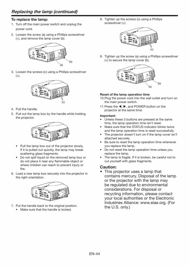
EN-44
Replacing the lamp (continued)
To replace the lamp:1. Turn off the main power switch and unplug the
power cord.
2. Loosen the screw (a) using a Phillips screwdriver (+),andremovethelampcover(b).
(a)(b)
3. Loosen the screws (c) using a Phillips screwdriver (+).
(c)
4. Pull the handle.
5. Pull out the lamp box by the handle while holding the projector.
• Pull the lamp box out of the projector slowly. If it is pulled out quickly, the lamp may break scattering glass fragments.
• Do not spill liquid on the removed lamp box or do not place it near any flammable object or where children can reach to prevent injury or fire.
6. Load a new lamp box securely into the projector in the right orientation.
7. Put the handle back to the original position.• Make sure that the handle is locked.
8. Tighten up the screws (c) using a Phillips screwdriver(+).
(c)
9. Tighten up the screw (a) using a Phillips screwdriver (+)tosecurethelampcover(b).
(a)(b)
Reset of the lamp operation time10. Plug the power cord into the wall outlet and turn on
the main power switch.11. Press the , , and POWER button on the
projector at the same time.
Important:• Unlessthese3buttonsarepressedatthesame
time, the lamp operation time isn’t reset.• Make sure that the STATUS indicator blinks twice
and the lamp operation time is reset successfully.• The projector doesn’t turn on if the lamp cover isn’t
attached securely.• Be sure to reset the lamp operation time whenever
you replace the lamp.• Do not reset the lamp operation time unless you
replace the lamp.• The lamp is fragile. If it is broken, be careful not to
cut yourself with glass fragments.
Caution:• This projector uses a lamp that
contains mercury. Disposal of the lamp or the projector with the lamp may be regulated due to environmental considerations. For disposal or recycling information, please contact your local authorities or the Electronic Industries Alliance: www.eiae.org. (For the U.S. only.)
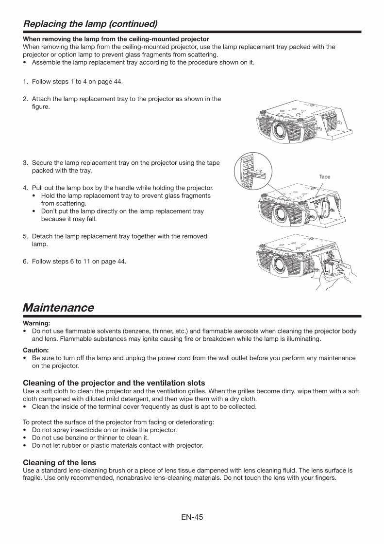
EN-45
When removing the lamp from the ceiling-mounted projectorWhen removing the lamp from the ceiling-mounted projector, use the lamp replacement tray packed with the projector or option lamp to prevent glass fragments from scattering.• Assemblethelampreplacementtrayaccordingtotheprocedureshownonit.
1. Follow steps 1 to 4 on page 44.
2. Attach the lamp replacement tray to the projector as shown in the figure.
3. Secure the lamp replacement tray on the projector using the tape packed with the tray.
4. Pull out the lamp box by the handle while holding the projector.• Hold the lamp replacement tray to prevent glass fragments
from scattering.• Don’t put the lamp directly on the lamp replacement tray
because it may fall.
5. Detach the lamp replacement tray together with the removed lamp.
6. Follow steps 6 to 11 on page 44.
MaintenanceWarning:• Do not use flammable solvents (benzene, thinner, etc.) and flammable aerosols when cleaning the projector body
and lens. Flammable substances may ignite causing fire or breakdown while the lamp is illuminating.
Caution:• Be sure to turn off the lamp and unplug the power cord from the wall outlet before you perform any maintenance
on the projector.
Cleaning of the projector and the ventilation slotsUse a soft cloth to clean the projector and the ventilation grilles. When the grilles become dirty, wipe them with a soft cloth dampened with diluted mild detergent, and then wipe them with a dry cloth.• Clean the inside of the terminal cover frequently as dust is apt to be collected.
To protect the surface of the projector from fading or deteriorating:• Do not spray insecticide on or inside the projector.• Do not use benzine or thinner to clean it.• Do not let rubber or plastic materials contact with projector.
Cleaning of the lensUse a standard lens-cleaning brush or a piece of lens tissue dampened with lens cleaning fluid. The lens surface is fragile. Use only recommended, nonabrasive lens-cleaning materials. Do not touch the lens with your fingers.
Replacing the lamp (continued)
Tape
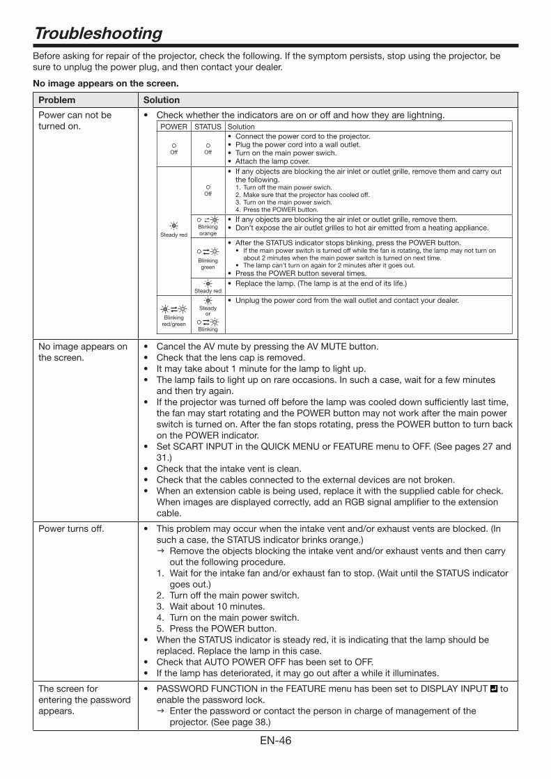
EN-46
TroubleshootingBefore asking for repair of the projector, check the following. If the symptom persists, stop using the projector, be sure to unplug the power plug, and then contact your dealer.
No image appears on the screen.
Problem Solution
Power can not be turned on.
• Checkwhethertheindicatorsareonoroffandhowtheyarelightning.POWER STATUS Solution
Off Off
• Connectthepowercordtotheprojector.• Plugthepowercordintoawalloutlet.• Turnonthemainpowerswich.• Attachthelampcover.
Steady red
Off
• Ifanyobjectsareblockingtheairinletoroutletgrille,removethemandcarryoutthe following.
Turn off the main power swich.1. Make sure that the projector has cooled off. 2. Turn on the main power swich.3. Press the POWER button.4.
Blinking orange
• Ifanyobjectsareblockingtheairinletoroutletgrille,removethem.• Don’texposetheairoutletgrillestohotairemittedfromaheatingappliance.
Blinking green
• AftertheSTATUSindicatorstopsblinking,pressthePOWERbutton.• Ifthemainpowerswitchisturnedoffwhilethefanisrotating,thelampmaynotturnon
about 2 minutes when the main power switch is turned on next time.• Thelampcan’tturnonagainfor2minutesafteritgoesout.
• PressthePOWERbuttonseveraltimes.
Steady red• Replacethelamp.(Thelampisattheendofitslife.)
Blinking red/green
Steadyor
Blinking
• Unplugthepowercordfromthewalloutletandcontactyourdealer.
No image appears on the screen.
• CanceltheAVmutebypressingtheAVMUTEbutton.• Checkthatthelenscapisremoved.• Itmaytakeabout1minuteforthelamptolightup.• Thelampfailstolightuponrareoccasions.Insuchacase,waitforafewminutes
and then try again. • Iftheprojectorwasturnedoffbeforethelampwascooleddownsufficientlylasttime,
the fan may start rotating and the POWER button may not work after the main power switch is turned on. After the fan stops rotating, press the POWER button to turn back on the POWER indicator.
• SetSCARTINPUTintheQUICKMENUorFEATUREmenutoOFF.(Seepages27and31.)
• Checkthattheintakeventisclean.• Checkthatthecablesconnectedtotheexternaldevicesarenotbroken.• Whenanextensioncableisbeingused,replaceitwiththesuppliedcableforcheck.
When images are displayed correctly, add an RGB signal amplifier to the extension cable.
Power turns off. • Thisproblemmayoccurwhentheintakeventand/orexhaustventsareblocked.(Insuch a case, the STATUS indicator brinks orange.) Remove the objects blocking the intake vent and/or exhaust vents and then carry
out the following procedure. 1. Wait for the intake fan and/or exhaust fan to stop. (Wait until the STATUS indicator
goes out.) 2. Turn off the main power switch. 3. Wait about 10 minutes.4. Turn on the main power switch.5. Press the POWER button.
• WhentheSTATUSindicatorissteadyred,itisindicatingthatthelampshouldbereplaced. Replace the lamp in this case.
• CheckthatAUTOPOWEROFFhasbeensettoOFF.• Ifthelamphasdeteriorated,itmaygooutafterawhileitilluminates.
The screen for entering the password appears.
• PASSWORDFUNCTIONintheFEATUREmenuhasbeensettoDISPLAYINPUT to enable the password lock. Enter the password or contact the person in charge of management of the
projector. (See page 38.)
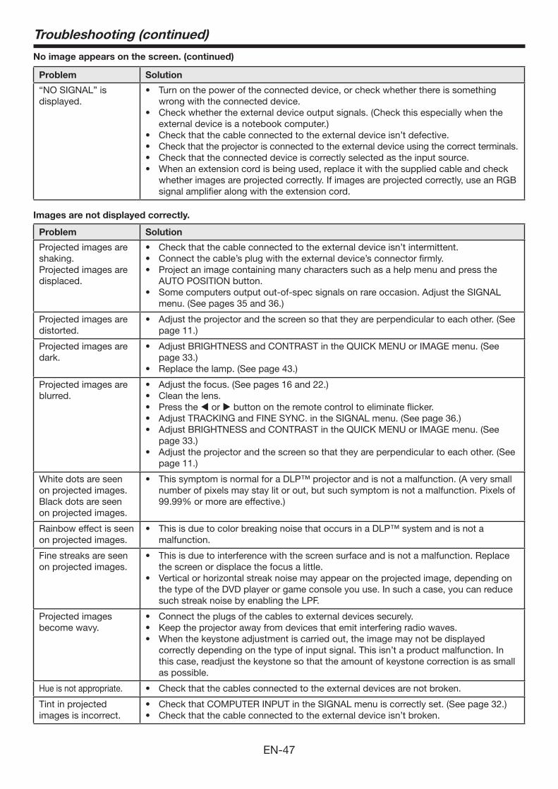
EN-47
Troubleshooting (continued)
No image appears on the screen. (continued)
Problem Solution
“NO SIGNAL” is displayed.
• Turnonthepoweroftheconnecteddevice,orcheckwhetherthereissomethingwrong with the connected device.
• Checkwhethertheexternaldeviceoutputsignals.(Checkthisespeciallywhentheexternal device is a notebook computer.)
• Checkthatthecableconnectedtotheexternaldeviceisn’tdefective.• Checkthattheprojectorisconnectedtotheexternaldeviceusingthecorrectterminals.• Checkthattheconnecteddeviceiscorrectlyselectedastheinputsource.• Whenanextensioncordisbeingused,replaceitwiththesuppliedcableandcheck
whether images are projected correctly. If images are projected correctly, use an RGB signal amplifier along with the extension cord.
Images are not displayed correctly.
Problem Solution
Projected images are shaking.Projected images are displaced.
• Checkthatthecableconnectedtotheexternaldeviceisn’tintermittent.• Connectthecable’splugwiththeexternaldevice’sconnectorfirmly.• Projectanimagecontainingmanycharacterssuchasahelpmenuandpressthe
AUTO POSITION button.• Somecomputersoutputout-of-specsignalsonrareoccasion.AdjusttheSIGNAL
menu. (See pages 35 and 36.)
Projected images are distorted.
• Adjusttheprojectorandthescreensothattheyareperpendiculartoeachother.(Seepage 11.)
Projected images are dark.
• AdjustBRIGHTNESSandCONTRASTintheQUICKMENUorIMAGEmenu.(Seepage 33.)
• Replacethelamp.(Seepage43.)
Projected images are blurred.
• Adjustthefocus.(Seepages16and22.)• Cleanthelens.• Pressthe or button on the remote control to eliminate flicker. • AdjustTRACKINGandFINESYNC.intheSIGNALmenu.(Seepage36.)• AdjustBRIGHTNESSandCONTRASTintheQUICK MENU or IMAGE menu. (See
page 33.)• Adjusttheprojectorandthescreensothattheyareperpendiculartoeachother.(See
page 11.)
White dots are seen on projected images. Black dots are seen on projected images.
• ThissymptomisnormalforaDLP™projectorandisnotamalfunction.(Averysmallnumber of pixels may stay lit or out, but such symptom is not a malfunction. Pixels of 99.99%ormoreareeffective.)
Rainbow effect is seen on projected images.
• ThisisduetocolorbreakingnoisethatoccursinaDLP™systemandisnotamalfunction.
Fine streaks are seen on projected images.
• Thisisduetointerferencewiththescreensurfaceandisnotamalfunction.Replacethe screen or displace the focus a little.
• Verticalorhorizontalstreaknoisemayappearontheprojectedimage,dependingonthe type of the DVD player or game console you use. In such a case, you can reduce such streak noise by enabling the LPF.
Projected images become wavy.
• Connecttheplugsofthecablestoexternaldevicessecurely.• Keeptheprojectorawayfromdevicesthatemitinterferingradiowaves.• Whenthekeystoneadjustmentiscarriedout,theimagemaynotbedisplayed
correctly depending on the type of input signal. This isn’t a product malfunction. In this case, readjust the keystone so that the amount of keystone correction is as small as possible.
Hue is not appropriate. • Checkthatthecablesconnectedtotheexternaldevicesarenotbroken.
Tint in projected images is incorrect.
• CheckthatCOMPUTERINPUTintheSIGNALmenuiscorrectlyset.(Seepage32.)• Checkthatthecableconnectedtotheexternaldeviceisn’tbroken.
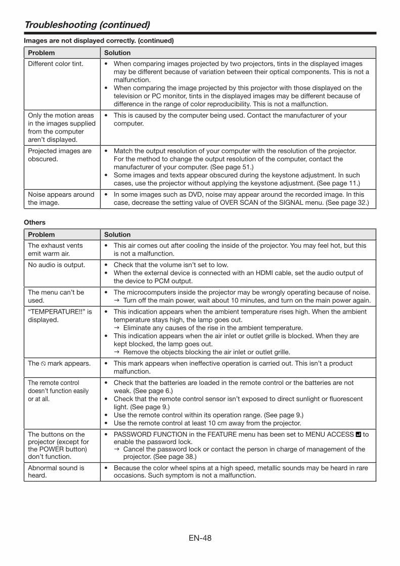
EN-48
Troubleshooting (continued)
Images are not displayed correctly. (continued)
Problem Solution
Different color tint. • Whencomparingimagesprojectedbytwoprojectors,tintsinthedisplayedimagesmay be different because of variation between their optical components. This is not a malfunction.
• Whencomparingtheimageprojectedbythisprojectorwiththosedisplayedonthetelevision or PC monitor, tints in the displayed images may be different because of difference in the range of color reproducibility. This is not a malfunction.
Only the motion areas in the images supplied from the computer aren’t displayed.
• Thisiscausedbythecomputerbeingused.Contactthemanufacturerofyourcomputer.
Projected images are obscured.
• Matchtheoutputresolutionofyourcomputerwiththeresolutionoftheprojector.For the method to change the output resolution of the computer, contact the manufacturer of your computer. (See page 51.)
• Someimagesandtextsappearobscuredduringthekeystoneadjustment.Insuchcases, use the projector without applying the keystone adjustment. (See page 11.)
Noise appears around the image.
• InsomeimagessuchasDVD,noisemayappeararoundtherecordedimage.Inthiscase, decrease the setting value of OVER SCAN of the SIGNAL menu. (See page 32.)
Others
Problem Solution
The exhaust vents emit warm air.
• Thisaircomesoutaftercoolingtheinsideoftheprojector.Youmayfeelhot,butthisis not a malfunction.
No audio is output. • Checkthatthevolumeisn’tsettolow.• WhentheexternaldeviceisconnectedwithanHDMIcable,settheaudiooutputof
the device to PCM output.
The menu can’t be used.
• Themicrocomputersinsidetheprojectormaybewronglyoperatingbecauseofnoise. Turn off the main power, wait about 10 minutes, and turn on the main power again.
“TEMPERATURE!!” is displayed.
• Thisindicationappearswhentheambienttemperatureriseshigh.Whentheambienttemperature stays high, the lamp goes out. Eliminate any causes of the rise in the ambient temperature.
• Thisindicationappearswhentheairinletoroutletgrilleisblocked.Whentheyarekept blocked, the lamp goes out. Remove the objects blocking the air inlet or outlet grille.
The mark appears. • Thismarkappearswhenineffectiveoperationiscarriedout.Thisisn’taproductmalfunction.
The remote control doesn’t function easily or at all.
• Checkthatthebatteriesareloadedintheremotecontrolorthebatteriesarenotweak. (See page 6.)
• Checkthattheremotecontrolsensorisn’texposedtodirectsunlightorfluorescentlight. (See page 9.)
• Usetheremotecontrolwithinitsoperationrange.(Seepage9.)• Usetheremotecontrolatleast10cmawayfromtheprojector.
The buttons on the projector (except for the POWER button) don’t function.
• PASSWORDFUNCTIONintheFEATUREmenuhasbeensettoMENUACCESS to enable the password lock. Cancel the password lock or contact the person in charge of management of the
projector. (See page 38.)
Abnormal sound is heard.
• Becausethecolorwheelspinsatahighspeed,metallicsoundsmaybeheardinrareoccasions. Such symptom is not a malfunction.

EN-49
Troubleshooting (continued)
If the following problem occurs after the lamp is replaced, check the following first.
Problem Solution
The projector does not turn on.
• Fitthelampcoversecurely.(Seepages43and44.)• Resetthelampoperatingtime.(Seepage44.)
The STATUS indicator blinks.
• Resetthelampoperatingtime.(Seepage44.)
Kensington LockThis projector has a Kensington Security Standard connector for use with Kensington MicroSaver Security System. Refer to the information that came with the Kensington System for instructions on how to use it to secure the projector. Please contact Kensington Technology Group below.Kensington Technology Group2855 Campus DriveSan Mateo, CA 94403, U.S.A.
Phone:+1-(650)572-2700 Fax:+1-(650)572-9675
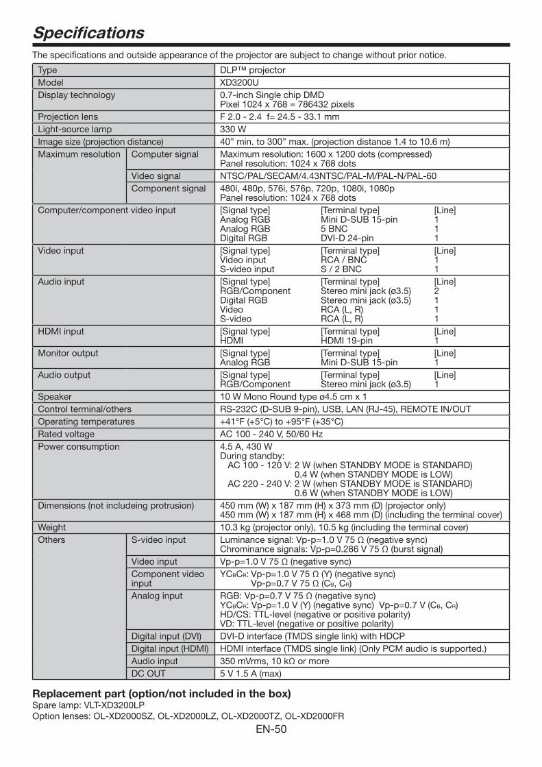
EN-50
SpecificationsThe specifications and outside appearance of the projector are subject to change without prior notice.
Type DLP™ projectorModel XD3200UDisplay technology 0.7-inch Single chip DMD
Pixel 1024 x 768 = 786432 pixelsProjection lens F 2.0 - 2.4 f= 24.5 - 33.1 mmLight-source lamp 330 WImage size (projection distance) 40” min. to 300” max. (projection distance 1.4 to 10.6 m)Maximum resolution Computer signal Maximum resolution: 1600 x 1200 dots (compressed)
Panel resolution: 1024 x 768 dotsVideo signal NTSC/PAL/SECAM/4.43NTSC/PAL-M/PAL-N/PAL-60 Component signal 480i, 480p, 576i, 576p, 720p, 1080i, 1080p
Panel resolution: 1024 x 768 dotsComputer/component video input [Signal type] [Terminal type] [Line]
Analog RGB Mini D-SUB 15-pin 1Analog RGB 5 BNC 1Digital RGB DVI-D 24-pin 1
Video input [Signal type] [Terminal type] [Line]Video input RCA / BNC 1 S-video input S / 2 BNC 1
Audio input [Signal type] [Terminal type] [Line]RGB/Component Stereominijack(ø3.5) 2DigitalRGB Stereominijack(ø3.5) 1Video RCA (L, R) 1S-video RCA (L, R) 1
HDMI input [Signal type] [Terminal type] [Line]HDMI HDMI 19-pin 1
Monitor output [Signal type] [Terminal type] [Line]Analog RGB Mini D-SUB 15-pin 1
Audio output [Signal type] [Terminal type] [Line]RGB/Component Stereominijack(ø3.5) 1
Speaker 10WMonoRoundtypeø4.5cmx1Control terminal/others RS-232C (D-SUB 9-pin), USB, LAN (RJ-45), REMOTE IN/OUTOperating temperatures +41°F(+5°C)to+95°F(+35°C) Rated voltage AC 100 - 240 V, 50/60 HzPower consumption 4.5 A, 430 W
During standby: AC 100 - 120 V: 2 W (when STANDBY MODE is STANDARD)
0.4 W (when STANDBY MODE is LOW)AC 220 - 240 V: 2 W (when STANDBY MODE is STANDARD)
0.6 W (when STANDBY MODE is LOW)Dimensions (not includeing protrusion) 450 mm (W) x 187 mm (H) x 373 mm (D) (projector only)
450 mm (W) x 187 mm (H) x 468 mm (D) (including the terminal cover)Weight 10.3 kg (projector only), 10.5 kg (including the terminal cover)Others S-video input Luminance signal: Vp-p=1.0 V 75 Ω (negative sync)
Chrominance signals: Vp-p=0.286 V 75 Ω (burst signal)Video input Vp-p=1.0 V 75 Ω (negative sync)Component video input
YCBCR: Vp-p=1.0 V 75 Ω (Y) (negative sync) Vp-p=0.7 V 75 Ω (CB, CR)
Analog input RGB: Vp-p=0.7 V 75 Ω (negative sync)YCBCR: Vp-p=1.0 V (Y) (negative sync) Vp-p=0.7 V (CB, CR)HD/CS: TTL-level (negative or positive polarity)VD: TTL-level (negative or positive polarity)
Digital input (DVI) DVI-D interface (TMDS single link) with HDCPDigital input (HDMI) HDMI interface (TMDS single link) (Only PCM audio is supported.)Audio input 350 mVrms, 10 kΩ or more DC OUT 5 V 1.5 A (max)
Replacement part (option/not included in the box)Spare lamp: VLT-XD3200LPOption lenses: OL-XD2000SZ, OL-XD2000LZ, OL-XD2000TZ, OL-XD2000FR
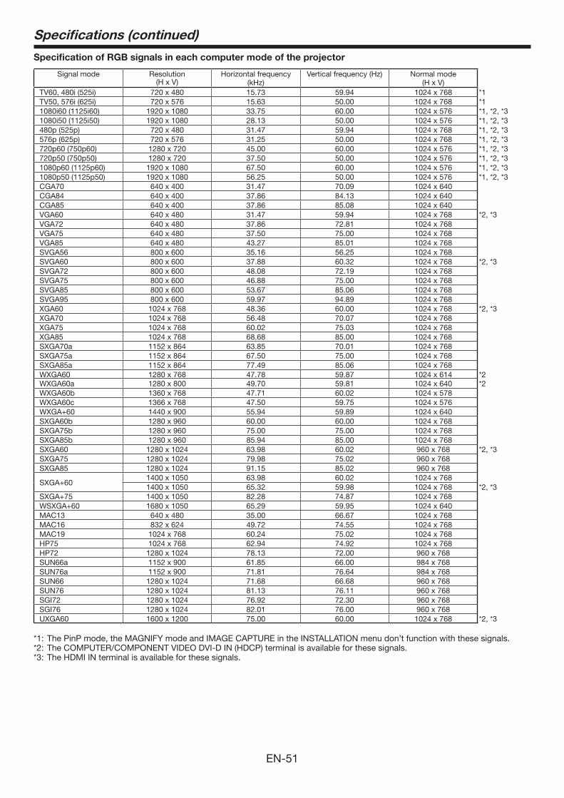
EN-51
Specifications (continued)
Specification of RGB signals in each computer mode of the projector
Signal mode Resolution(H x V)
Horizontal frequency (kHz)
Vertical frequency (Hz) Normal mode(H x V)
TV60, 480i (525i) 720 x 480 15.73 59.94 1024 x 768 *1TV50, 576i (625i) 720 x 576 15.63 50.00 1024 x 768 *11080i60 (1125i60) 1920 x 1080 33.75 60.00 1024 x 576 *1, *2, *31080i50 (1125i50) 1920 x 1080 28.13 50.00 1024 x 576 *1, *2, *3480p (525p) 720 x 480 31.47 59.94 1024 x 768 *1, *2, *3576p (625p) 720 x 576 31.25 50.00 1024 x 768 *1, *2, *3720p60 (750p60) 1280 x 720 45.00 60.00 1024 x 576 *1, *2, *3720p50 (750p50) 1280 x 720 37.50 50.00 1024 x 576 *1, *2, *31080p60 (1125p60) 1920 x 1080 67.50 60.00 1024 x 576 *1, *2, *31080p50 (1125p50) 1920 x 1080 56.25 50.00 1024 x 576 *1, *2, *3CGA70 640 x 400 31.47 70.09 1024 x 640CGA84 640 x 400 37.86 84.13 1024 x 640CGA85 640 x 400 37.86 85.08 1024 x 640VGA60 640 x 480 31.47 59.94 1024 x 768 *2, *3VGA72 640 x 480 37.86 72.81 1024 x 768VGA75 640 x 480 37.50 75.00 1024 x 768VGA85 640 x 480 43.27 85.01 1024 x 768SVGA56 800 x 600 35.16 56.25 1024 x 768SVGA60 800 x 600 37.88 60.32 1024 x 768 *2, *3SVGA72 800 x 600 48.08 72.19 1024 x 768SVGA75 800 x 600 46.88 75.00 1024 x 768SVGA85 800 x 600 53.67 85.06 1024 x 768SVGA95 800 x 600 59.97 94.89 1024 x 768XGA60 1024 x 768 48.36 60.00 1024 x 768 *2, *3XGA70 1024 x 768 56.48 70.07 1024 x 768XGA75 1024 x 768 60.02 75.03 1024 x 768XGA85 1024 x 768 68.68 85.00 1024 x 768SXGA70a 1152 x 864 63.85 70.01 1024 x 768SXGA75a 1152 x 864 67.50 75.00 1024 x 768SXGA85a 1152 x 864 77.49 85.06 1024 x 768WXGA60 1280 x 768 47.78 59.87 1024 x 614 *2WXGA60a 1280 x 800 49.70 59.81 1024 x 640 *2WXGA60b 1360 x 768 47.71 60.02 1024 x 578WXGA60c 1366 x 768 47.50 59.75 1024 x 576WXGA+60 1440 x 900 55.94 59.89 1024 x 640SXGA60b 1280 x 960 60.00 60.00 1024 x 768SXGA75b 1280 x 960 75.00 75.00 1024 x 768SXGA85b 1280 x 960 85.94 85.00 1024 x 768SXGA60 1280 x 1024 63.98 60.02 960 x 768 *2, *3SXGA75 1280 x 1024 79.98 75.02 960 x 768SXGA85 1280 x 1024 91.15 85.02 960 x 768
SXGA+601400 x 1050 63.98 60.02 1024 x 7681400 x 1050 65.32 59.98 1024 x 768 *2, *3
SXGA+75 1400 x 1050 82.28 74.87 1024 x 768WSXGA+60 1680 x 1050 65.29 59.95 1024 x 640MAC13 640 x 480 35.00 66.67 1024 x 768MAC16 832 x 624 49.72 74.55 1024 x 768MAC19 1024 x 768 60.24 75.02 1024 x 768HP75 1024 x 768 62.94 74.92 1024 x 768HP72 1280 x 1024 78.13 72.00 960 x 768SUN66a 1152 x 900 61.85 66.00 984 x 768SUN76a 1152 x 900 71.81 76.64 984 x 768SUN66 1280 x 1024 71.68 66.68 960 x 768SUN76 1280 x 1024 81.13 76.11 960 x 768SGI72 1280 x 1024 76.92 72.30 960 x 768SGI76 1280 x 1024 82.01 76.00 960 x 768UXGA60 1600 x 1200 75.00 60.00 1024 x 768 *2, *3
*1: The PinP mode, the MAGNIFY mode and IMAGE CAPTURE in the INSTALLATION menu don’t function with these signals.*2: The COMPUTER/COMPONENT VIDEO DVI-D IN (HDCP) terminal is available for these signals.*3: The HDMI IN terminal is available for these signals.
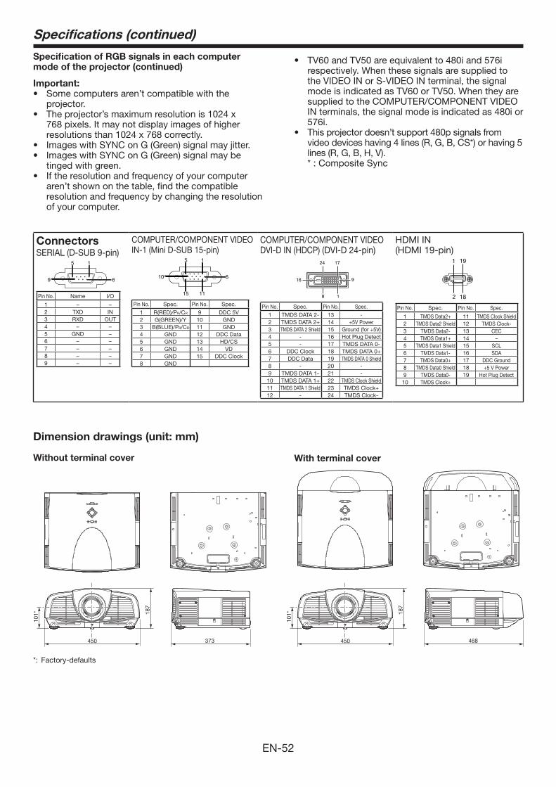
EN-52
450
187
101*
373
Dimension drawings (unit: mm)
Specifications (continued)
Specification of RGB signals in each computer mode of the projector (continued)
Important:• Some computers aren’t compatible with the
projector.• The projector’s maximum resolution is 1024 x
768 pixels. It may not display images of higher resolutions than 1024 x 768 correctly.
• Images with SYNC on G (Green) signal may jitter.• Images with SYNC on G (Green) signal may be
tinged with green.• If the resolution and frequency of your computer
aren’t shown on the table, find the compatible resolution and frequency by changing the resolution of your computer.
• TV60andTV50areequivalentto480iand576irespectively. When these signals are supplied to the VIDEO IN or S-VIDEO IN terminal, the signal mode is indicated as TV60 or TV50. When they are supplied to the COMPUTER/COMPONENT VIDEO IN terminals, the signal mode is indicated as 480i or 576i.
• Thisprojectordoesn’tsupport480psignalsfromvideo devices having 4 lines (R, G, B, CS*) or having 5 lines (R, G, B, H, V).
* : Composite Sync
468450
187
101*
Without terminal cover With terminal cover
ConnectorsSERIAL (D-SUB 9-pin)
15
69
Pin No. Name I/O
1 – –2 TXD IN3 RXD OUT4 – –5 GND –6 – –7 – –8 – –9 – –
COMPUTER/COMPONENT VIDEO IN-1 (Mini D-SUB 15-pin)
15
11
610
15
Pin No. Spec. Pin No. Spec.
1 R(RED)/PR/CR 9 DDC 5V2 G(GREEN)/Y 10 GND3 B(BLUE)/PB/CB 11 GND4 GND 12 DDC Data5 GND 13 HD/CS6 GND 14 VD7 GND 15 DDC Clock8 GND
COMPUTER/COMPONENT VIDEO DVI-D IN (HDCP) (DVI-D 24-pin)
1724
16 9
8 1
Pin No. Spec. Pin No. Spec.
1 TMDS DATA 2- 13 -2 TMDS DATA2+ 14 +5VPower3 TMDS DATA 2 Shield 15 Ground(for+5V)4 - 16 Hot Plug Detect5 - 17 TMDS DATA 0-6 DDC Clock 18 TMDS DATA0+7 DDC Data 19 TMDS DATA 0 Shield8 - 20 -9 TMDS DATA 1- 21 -10 TMDS DATA1+ 22 TMDS Clock Shield11 TMDS DATA 1 Shield 23 TMDS Clock+12 - 24 TMDS Clock-
HDMI IN(HDMI 19-pin)
191
2 18
Pin No. Spec. Pin No. Spec.
1 TMDSData2+ 11 TMDS Clock Shield2 TMDS Data2 Shield 12 TMDS Clock-3 TMDS Data2- 13 CEC4 TMDSData1+ 14 –5 TMDS Data1 Shield 15 SCL6 TMDS Data1- 16 SDA7 TMDSData0+ 17 DDC Ground8 TMDS Data0 Shield 18 +5VPower9 TMDS Data0- 19 Hot Plug Detect10 TMDSClock+
*: Factory-defaults

1 Zusho Baba, Nagaokakyo-City, Kyoto JapanMITSUBISHI ELECTRIC CORPORATION
A


