XCP Pro User Manual
67
XC series Edit Tool XCP Pro User Manual Xinje Electronic Co., Ltd.
-
Upload
mihai-bartos -
Category
Documents
-
view
304 -
download
6
Transcript of XCP Pro User Manual
XC series Edit Tool XCP Pro
User Manual
Xinje Electronic Co., Ltd.


XCP Pro User Manual
2
Catalog
1、Use explanation ...............................................................................................4
1-2. Install steps ...............................................................................................5
1-3. Uninstall steps...........................................................................................7
2、Basic operation ................................................................................................9
2-1. Open and close the XCP Pro ..................................................................10
2-3. Add and delete the PLC mode.............................................................13
3、Basic introduction of edit environment.......................................................15
3-1.The basic form of interface......................................................................16
3-2. Conventional Toolbar .............................................................................17
3-3. PLC Toolbar.........................................................................................17
3-4. Ladder Chart Input Bar...........................................................................18
3-5. Other .......................................................................................................19
3-6. Menu Bar Introduction ...........................................................................19
3-6-1. “File” ...................................................................................................19
3-6-2. “Edit”...................................................................................................20
3-6-3. “Search/Replace” ................................................................................20
3-6-4. “View”.................................................................................................21
3-6-5. “PLC Operate” ....................................................................................21
3-6-6. “PLC Setting”......................................................................................22
3-6-7. “Option” ..............................................................................................22
3-6-8. “Window”............................................................................................22
3-6-9. “Help”..................................................................................................23
3-7. Project bar...............................................................................................23
3-8. Shortcut key instruction..........................................................................24
4、Simple function realization ..........................................................................24
4-1. Online .....................................................................................................25
4-2. Download/Upload program, PLC state control ......................................27
4-3. Set PLC initial value, upload/download data ......................................28
4-3-1. Initial value settings ............................................................................28
4-3-2. Upload/Download data........................................................................29
4-4. PLCand module information enquiry..................................................29
4-4-1. PLC main unit information ..............................................................29
4-4-2. BD board information ......................................................................30
4-4-3. Expansion module information ...........................................................30
4-4-4. Scan cycle............................................................................................31
4-4-5. Clock information ...............................................................................31
4-4-6. Error information.................................................................................31
XCP Pro User Manual
3
4-5. PLC Initialization ................................................................................32
4-6. Lock/Unlock program.............................................................................32
4-6-1. Password settings ................................................................................32
4-6-2. Lock/Unlock........................................................................................33
4-6-3. The default password decryption settings ...........................................33
4-7. Print ........................................................................................................33
5、Programme operation...................................................................................34
5-1. Programme mode....................................................................................35
5-2. Input instruction......................................................................................36
5-2-1. Instruction prompt ...............................................................................36
5-2-2. Input node............................................................................................37
5-2-3. Input loop ............................................................................................38
5-2-4. Special instruction ...............................................................................40
5-3. Ladder chart edit .....................................................................................44
5-3-1. Horizontal line and vertical line operation..........................................44
5-3-2. Node and row operation ......................................................................45
5-3-3. Edit comment ......................................................................................46
5-3-4. Ladder chart copy and cut ...................................................................48
5-3-5. Ladder chart instruction management .................................................49
5-4. Relevant config.......................................................................................51
5-4-1. PLCserial port settings ........................................................................51
5-4-2. Password settings ................................................................................52
5-4-3. BD board settings ................................................................................53
5-4-4. Can-bus comunication config..............................................................54
5-4-5. Power-off retentive save memory settings ..........................................55
5-4-6. Expansion module settings..................................................................56
5-4-7. I/O settings .......................................................................................56
5-4-8. Comunication mode settings ...............................................................58
5-4-9. TCP/IP settings.................................................................................59
5-4-10. Function block list.............................................................................59
5-5. Soft element monitor ..............................................................................61
5-5-1. Soft element comment.........................................................................61
5-5-2. Free monitor ........................................................................................62
5-5-3. Data monitor........................................................................................62
5-5-4. Ladder chart monitor...........................................................................63
5-5-5. Information bar....................................................................................64
5-5-6. Status bar .............................................................................................65
XCP Pro User Manual
4
1、Use explanation
This chapter focuses on XC XCP Pro PC software installation system requirements, installation
and unloading steps.
1-1.Install system requirements
1-2.Install steps
1-3.Uninstall steps
XCP Pro User Manual
5
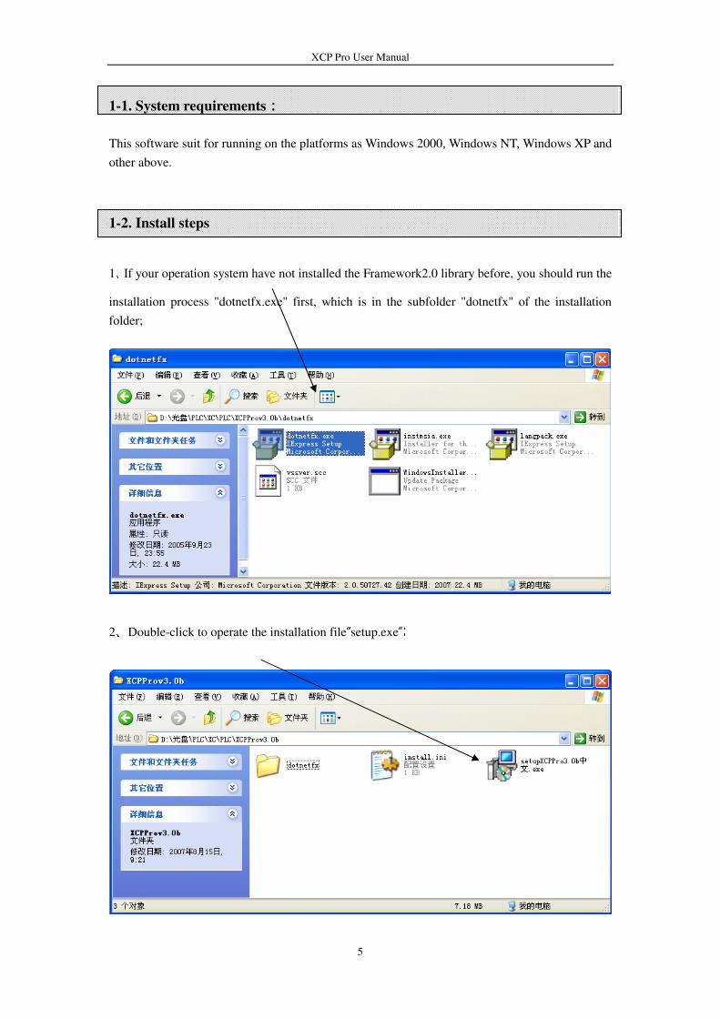
1-1. System requirements:
This software suit for running on the platforms as Windows 2000, Windows NT, Windows XP and
other above.
1-2. Install steps
1、If your operation system have not installed the Framework2.0 library before, you should run the
installation process "dotnetfx.exe" first, which is in the subfolder "dotnetfx" of the installation
folder;
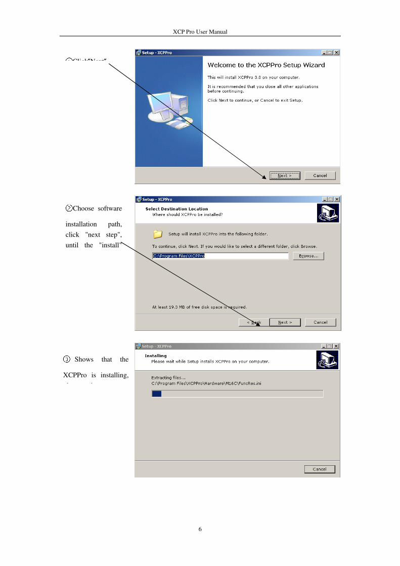
2、Double-click to operate the installation file“setup.exe”;
XCP Pro User Manual
6
①Click“Next”.
②Choose software
installation path,
click "next step",
until the "install"
③ Shows that the
XCPPro is installing,
please wait.
XCP Pro User Manual
7
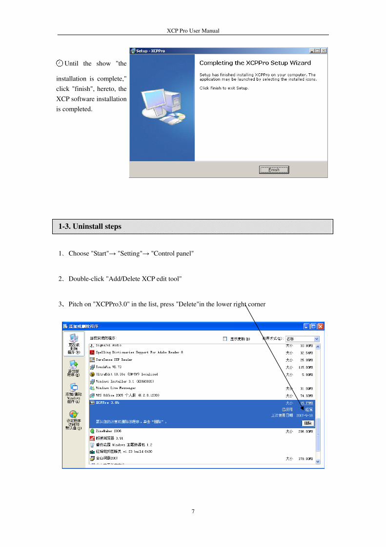
1-3. Uninstall steps
1、Choose "Start"→ "Setting"→ "Control panel"
2、Double-click "Add/Delete XCP edit tool"
3、Pitch on "XCPPro3.0" in the list, press "Delete"in the lower right corner
④Until the show "the
installation is complete,"
click "finish", hereto, the
XCP software installation
is completed.
XCP Pro User Manual
8
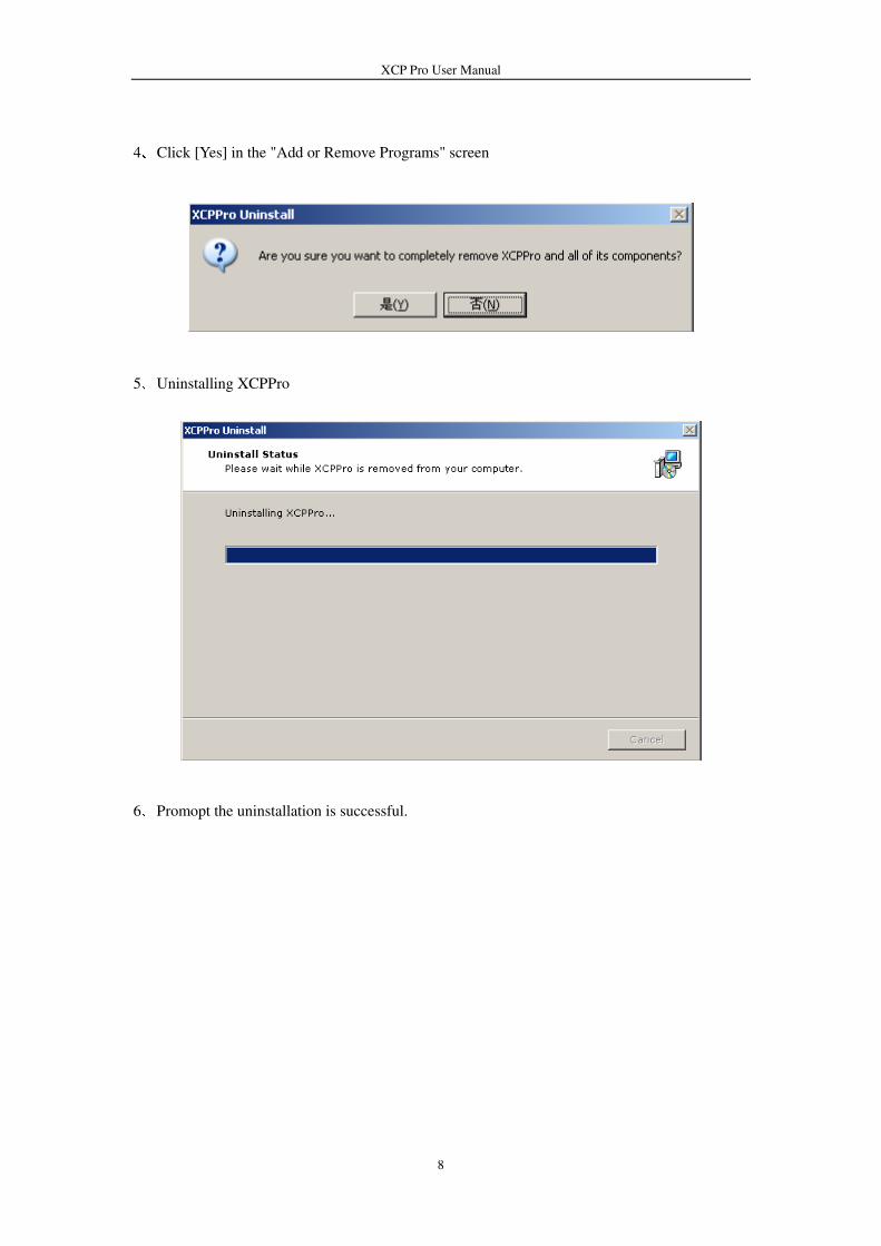
4、Click [Yes] in the "Add or Remove Programs" screen
5、Uninstalling XCPPro
6、Promopt the uninstallation is successful.

XCP Pro User Manual
9
2、Basic operation
This chapter focuses on the most basic operations in XCP Pro, including open and close software,
create and open the project, add and delete PLC type in the same project.
2-1.Open and close the XCP Pro
2-2.Create and open the project
2-3.Add and delete PLC type
XCP Pro User Manual
10
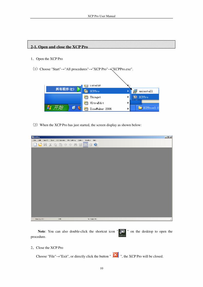
2-1. Open and close the XCP Pro
1、Open the XCP Pro (1)Choose "Start"→"All procedures"→"XCP Pro"→"XCPPro.exe".
(2)When the XCP Pro has just started, the screen display as shown below:
Note: You can also double-click the shortcut icon " " on the desktop to open the
procedure.
2、Close the XCP Pro
Choose "File"→"Exit", or directly click the button " ", the XCP Pro will be closed.
XCP Pro User Manual
11
2-2. Create and open the project
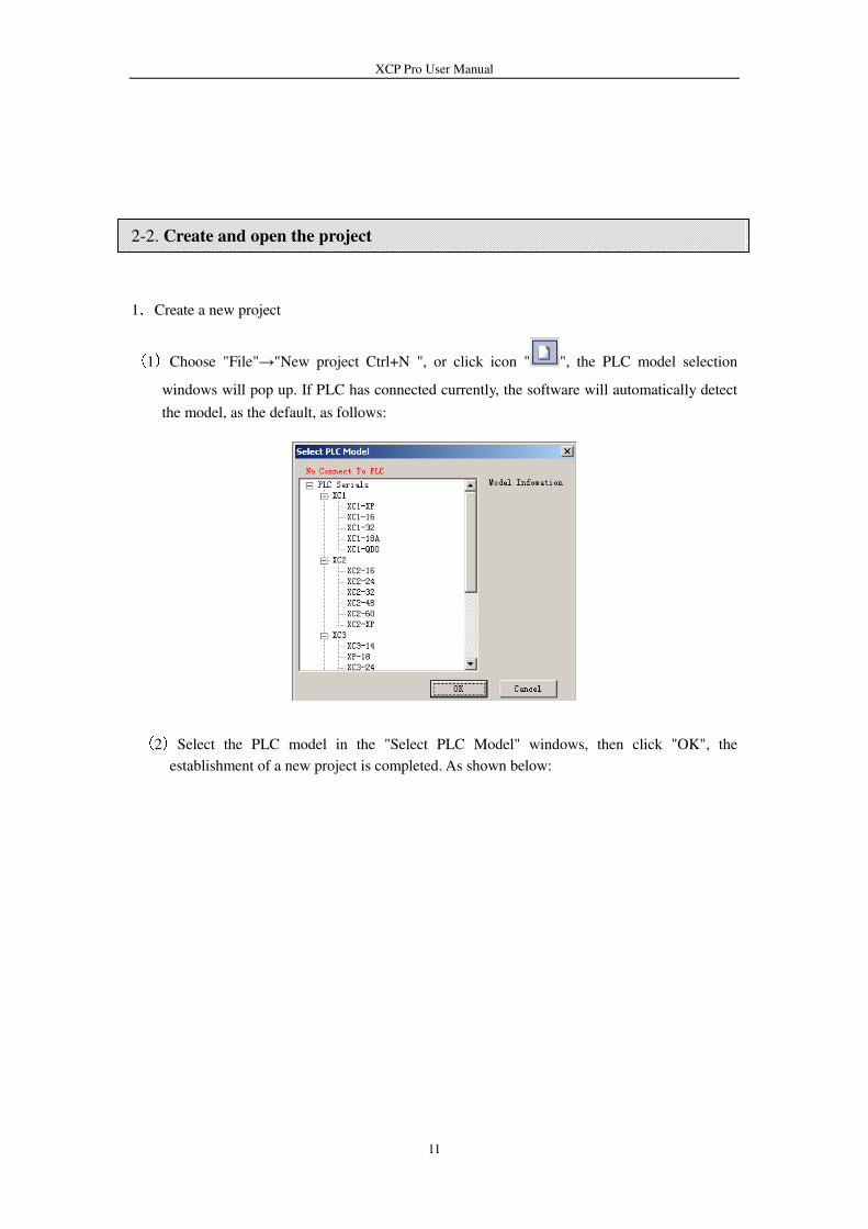
1、Create a new project (1)Choose "File"→"New project Ctrl+N ", or click icon " ", the PLC model selection
windows will pop up. If PLC has connected currently, the software will automatically detect
the model, as the default, as follows:
(2)Select the PLC model in the "Select PLC Model" windows, then click "OK", the
establishment of a new project is completed. As shown below:
XCP Pro User Manual
12
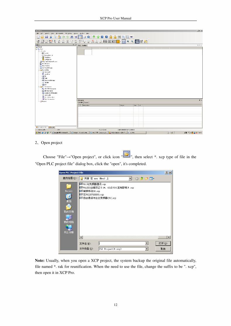
2、Open project
Choose "File"→"Open project", or click icon " ", then select *. xcp type of file in the
"Open PLC project file" dialog box, click the "open", it's completed.
Note: Usually, when you open a XCP project, the system backup the original file automatically,
file named *. rak for reunification. When the need to use the file, change the suffix to be ". xcp",
then open it in XCP Pro.
XCP Pro User Manual
13
2-3. Add and delete the PLC mode
When project new created, it is defaulted for PLC1. When user needs to edit a number of
PLCs, they can add multi-object to a interface.
1、 Add PLC
Method 1:Click "File"→"Add PLC".
Method 2:In project column which is on the left side, right-click "PLC1"→"Add PLC", as
follows:
When PLC is added successfully, it will be named "PLC2" acquiescently, and the project column
in the left side will change also, as shown below:
When edit different PLCs, only need to click the plc simply. What's more, users can also modify
appropriate name, edit communication mode, change models or delete operation on the
corresponding PLC .
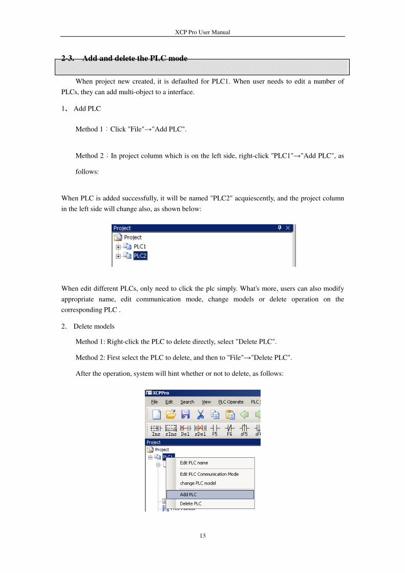
2、 Delete models
Method 1: Right-click the PLC to delete directly, select "Delete PLC".
Method 2: First select the PLC to delete, and then to "File"→"Delete PLC".
After the operation, system will hint whether or not to delete, as follows:

XCP Pro User Manual
14
To confirm the deletion, click "OK", otherwise, click "Cancel."
Note: The code between different PLC editor objects can copy each other, the code between
different projects can also copy and paste.

XCP Pro User Manual
15
3、Basic introduction of edit environment
This chapter focuses on basic structure of XCP Pro software, the main function of the Toolbar, the
menu bar, the project bar, and shortcut key in common use.
3-1.The basic form of interface
3-2.Conventional Toolbar
3-3.PLCToolbar
3-4.Ladder input Toolbar
3-5.Else
3-6.Menu bar
3-7.Project bar
3-8.Shortcut key introduction
XCP Pro User Manual
16
3-1.The basic form of interface
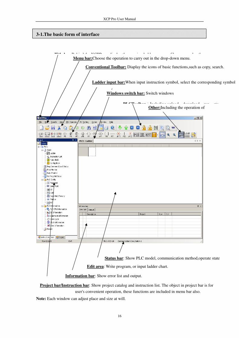
Note: Each window can adjust place and size at will.
Title bar:Behind the XCPPro,display the opening ladder program file name and path. Menu bar:Choose the operation to carry out in the drop-down menu.
Conventional Toolbar: Diaplay the icons of basic functions,such as copy, search.
Project bar/Instruction bar: Show project catalog and instruction list. The object in project bar is for
user's convenient operation, these functions are included in menu bar also.
Ladder input bar:When input instruction symbol, select the corresponding symbol
icon.
PLCToolbar:Including upload、download、run、etc. Other:Including the operation of
Information bar: Show error list and output.
Status bar: Show PLC model, communication method,operate state
Windows switch bar: Switch windows
Edit area: Write program, or input ladder chart.
XCP Pro User Manual
17
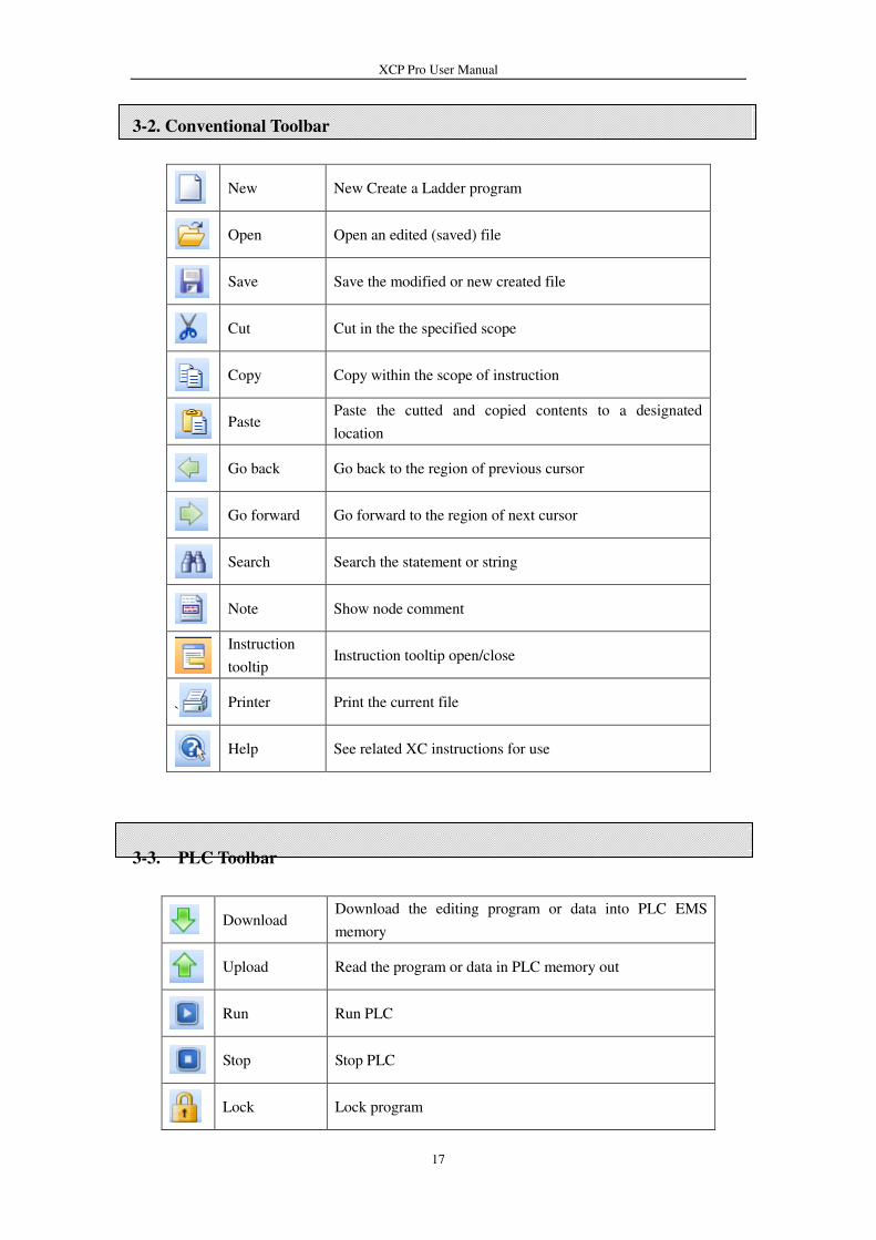
3-2. Conventional Toolbar
New New Create a Ladder program
Open Open an edited (saved) file
Save Save the modified or new created file
Cut Cut in the the specified scope
Copy Copy within the scope of instruction
Paste
Paste the cutted and copied contents to a designated
location
Go back Go back to the region of previous cursor
Go forward Go forward to the region of next cursor
Search Search the statement or string
Note Show node comment
Instruction
tooltip Instruction tooltip open/close
` Printer Print the current file
Help See related XC instructions for use
3-3. PLC Toolbar
Download
Download the editing program or data into PLC EMS
memory
Upload Read the program or data in PLC memory out
Run Run PLC
Stop Stop PLC
Lock Lock program
XCP Pro User Manual
18
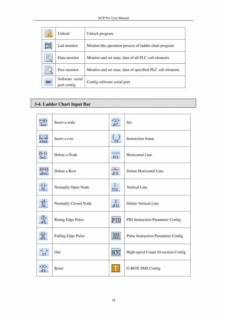
Unlock Unlock program
Lad monitor Monitor the operation process of ladder chart program
Data monitor Monitor and set state, data of all PLC soft elements
Free monitor Monitor and set state, data of specified PLC soft elements
Software serial
port config Config software serial port
3-4. Ladder Chart Input Bar
Insert a node
Set
Insert a row
Instruction frame
Delete a Node
Horizontal Line
Delete a Row
Delete Horizontal Line
Normally Open Node
Vertical Line
Normally Closed Node
Delete Vertical Line
Rising Edge Pulse
PID Instruction Parameter Config
Falling Edge Pulse
Pulse Instruction Parameter Config
Out
High-speed Count 24-section Config
Reset
G-BOX SMS Config
XCP Pro User Manual
19
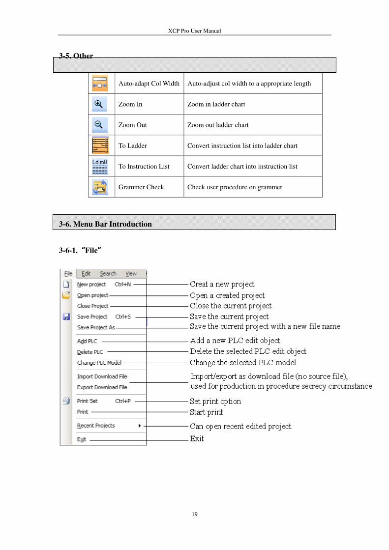
3-5. Other
Auto-adapt Col Width Auto-adjust col width to a appropriate length
Zoom In Zoom in ladder chart
Zoom Out Zoom out ladder chart
To Ladder Convert instruction list into ladder chart
To Instruction List Convert ladder chart into instruction list
Grammer Check Check user procedure on grammer
3-6. Menu Bar Introduction
3-6-1. “File”
XCP Pro User Manual
20
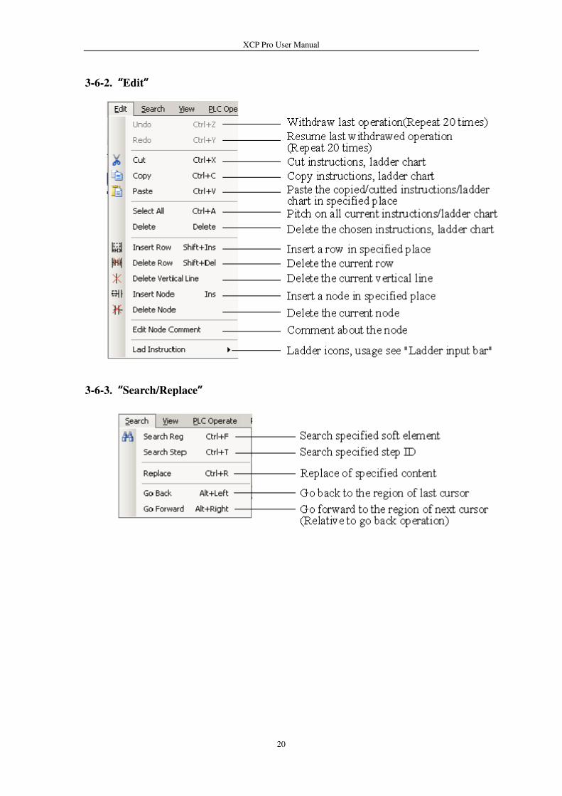
3-6-2. “Edit”
3-6-3. “Search/Replace”
XCP Pro User Manual
21
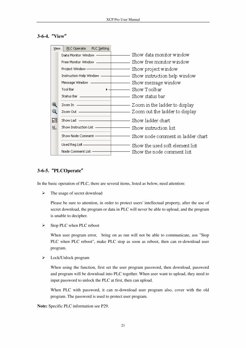
3-6-4. “View”
3-6-5. “PLCOperate”
In the basic operation of PLC, there are several items, listed as below, need attention:
� The usage of secret download
Please be sure to attention, in order to protect users' intellectual property, after the use of
secret download, the program or data in PLC will never be able to upload, and the program
is unable to decipher.
� Stop PLC when PLC reboot
When user program error, bring on as run will not be able to communicate, use "Stop
PLC when PLC reboot", make PLC stop as soon as reboot, then can re-download user
program.
� Lock/Unlock program
When using the function, first set the user program password, then download, password
and program will be download into PLC together. When user want to upload, they need to
input password to unlock the PLC at first, then can upload.
When PLC with password, it can re-download user program also, cover with the old
program. The password is used to protect user program.
Note: Specific PLC information see P29.
XCP Pro User Manual
22
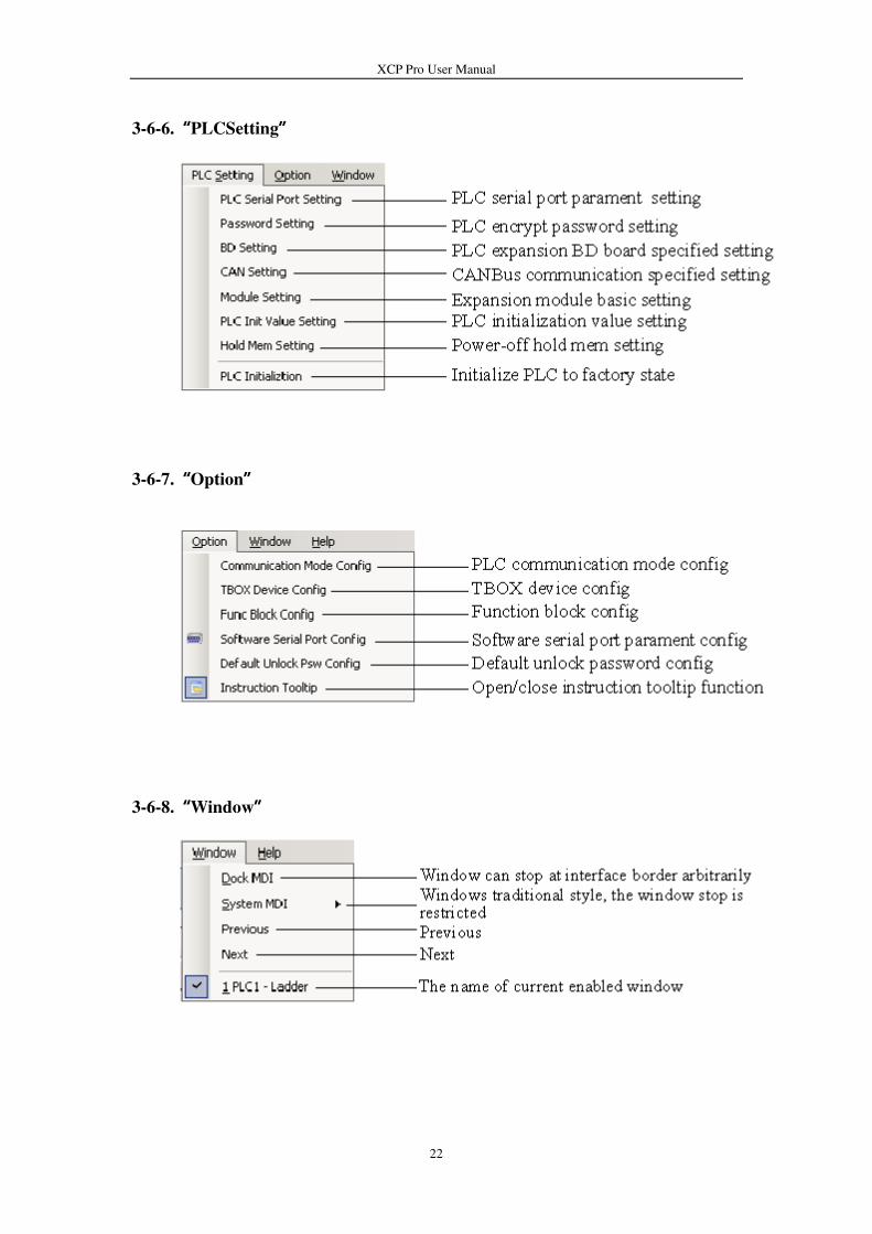
3-6-6. “PLCSetting”
3-6-7. “Option”
3-6-8. “Window”
XCP Pro User Manual
23
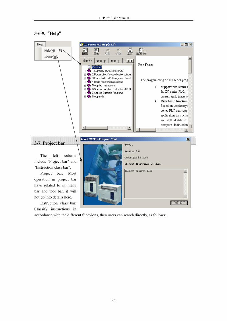
3-6-9. “Help”
3-7. Project bar
The left column
includs "Project bar" and
"Instruction class bar".
Project bar: Most
operation in project bar
have related to in menu
bar and tool bar, it will
not go into details here.
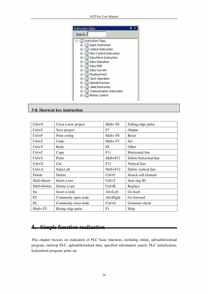
Instruction class bar:
Classify instructions in
accordance with the different funcyions, then users can search directly, as follows:
XCP Pro User Manual
24
3-8. Shortcut key instruction
4、Simple function realization
This chapter focuses on realization of PLC basic functions, including online, upload/download
program, run/stop PLC, upload/download data, specified information search, PLC initialization,
lock/unlock program, print, etc.
Ctrl+N Creat a new project Shift+ F6 Falling edge pulse
Ctrl+S Save project F7 Output
Ctrl+P Print config Shift+ F8 Reset
Ctrl+Z Undo Shift+ F7 Set
Ctrl+Y Redo F8 Other
Ctrl+C Copy F11 Horizontal line
Ctrl+V Paste Shift+F11 Delete horizontal line
Ctrl+X Cut F12 Vertical line
Ctrl+A Select all Shift+F12 Delete vertical line
Delete Delete Ctrl+F Search soft element
Shift+Insert Insert a raw Ctrl+T Sear step ID
Shift+Delete Delete a raw Ctrl+R Replace
Ins Insert a node Alt+Left Go back
F5 Commonly open node Alt+Right Go forward
F6 Commonly close node Ctrl+G Grammer check
Shift+ F5 Rising edge pulse F1 Help
XCP Pro User Manual
25
4-1. Online
1、 Click menu bar, "option"→"software serial port config", or click icon " "。
4-1.Online
4-2.Upload/download program, and PLC status control
4-3.Set PLC initialize value, upload/download data
4-4.PLC and module information enquire
4-5.PLC initialization
4-6.Lock/Unlock program
4-7.Print
XCP Pro User Manual
26
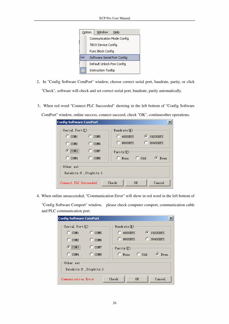
2、In "Config Software ComPort" window, choose correct serial port, baudrate, parity, or click
"Check", software will check and set correct serial port, baudrate, parity automatically.
3、When red word "Connect PLC Succeeded" showing in the left bottom of "Config Software
ComPort" window, online success, connect succeed, check "OK", continueother operations.
4、When online unsucceeded, "Communication Error" will show in red word in the left bottom of
"Config Software Comport" window, please check computer comport, communication cable
and PLC communication port.
XCP Pro User Manual
27
4-2. Download/Upload program, PLC state control
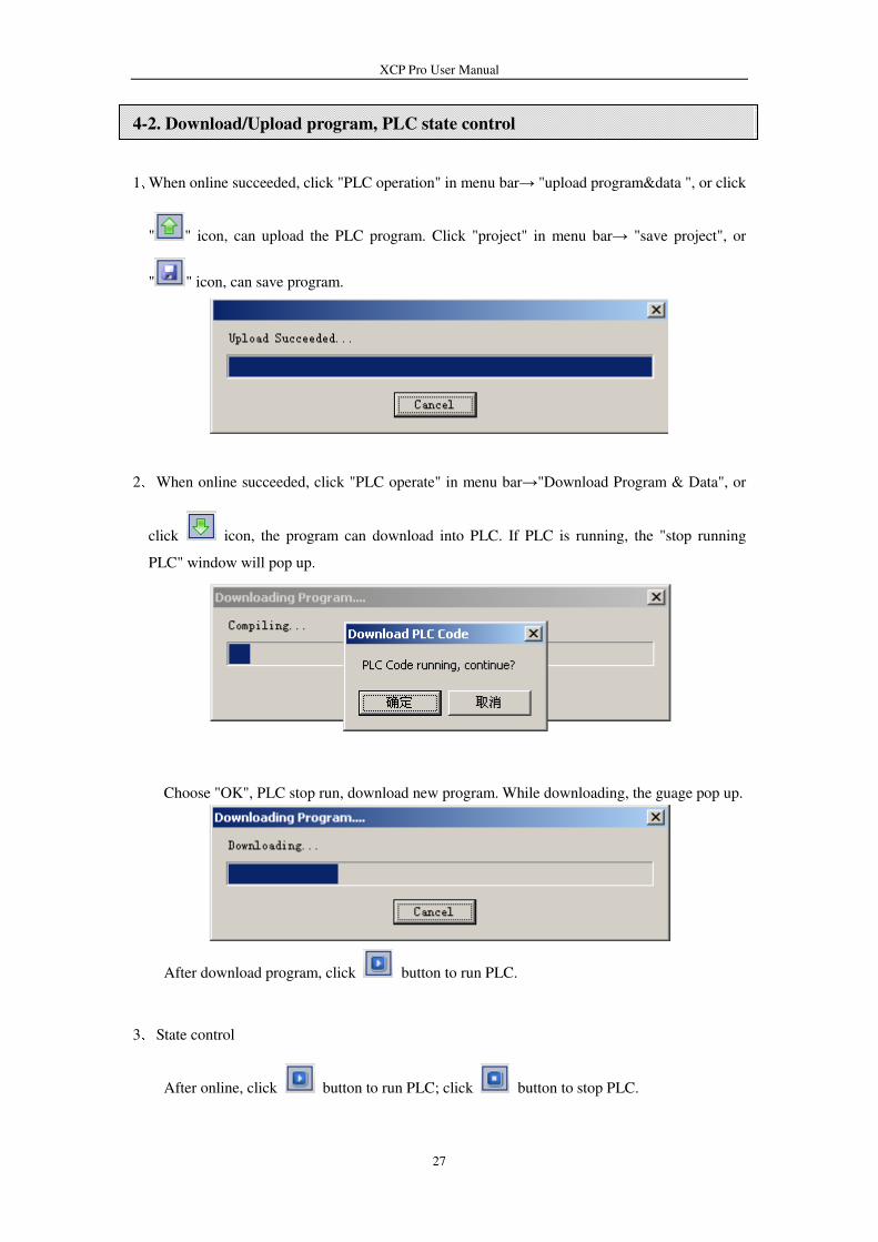
1、When online succeeded, click "PLC operation" in menu bar→ "upload program&data ", or click
" " icon, can upload the PLC program. Click "project" in menu bar→ "save project", or
" " icon, can save program.
2、When online succeeded, click "PLC operate" in menu bar→"Download Program & Data", or
click icon, the program can download into PLC. If PLC is running, the "stop running
PLC" window will pop up.
Choose "OK", PLC stop run, download new program. While downloading, the guage pop up.
After download program, click button to run PLC.
3、State control
After online, click button to run PLC; click button to stop PLC.
XCP Pro User Manual
28
4-3. Set PLC initial value, upload/download data
4-3-1. Initial value settings
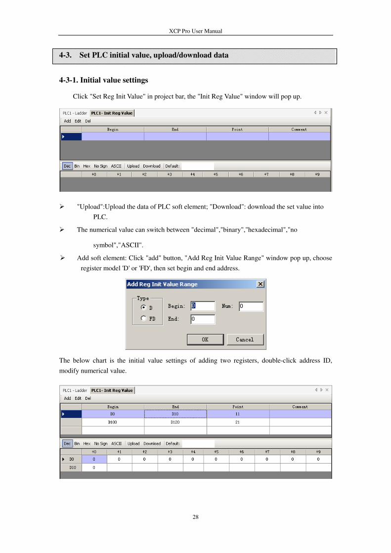
Click "Set Reg Init Value" in project bar, the "Init Reg Value" window will pop up.
� "Upload":Upload the data of PLC soft element; "Download": download the set value into
PLC.
� The numerical value can switch between "decimal","binary","hexadecimal","no
symbol","ASCII".
� Add soft element: Click "add" button, "Add Reg Init Value Range" window pop up, choose
register model 'D' or 'FD', then set begin and end address.
The below chart is the initial value settings of adding two registers, double-click address ID,
modify numerical value.
XCP Pro User Manual
29
4-3-2. Upload/Download data
Method 1: If the operation object is a part of address, set initial value at first, then click "upload"、"download" button.
Method 2: If operation object is the whole address, click "PLC operate" in menu bar→"Upload
data","Download data".
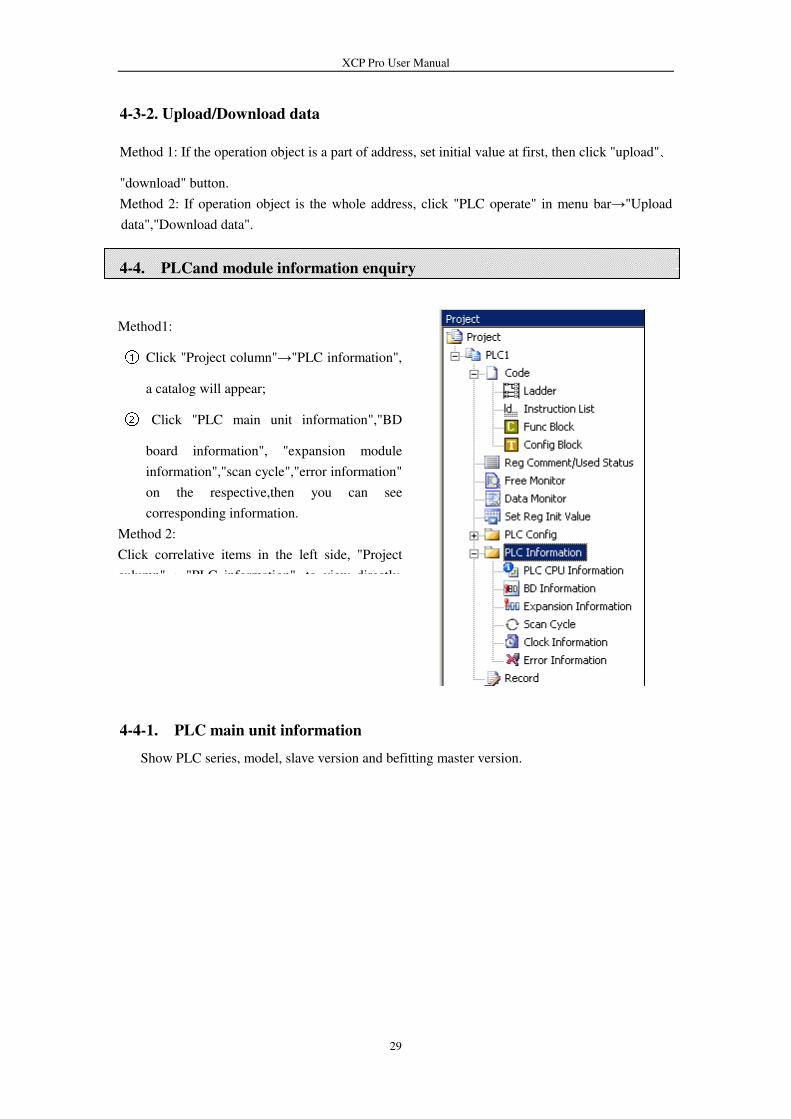
4-4. PLCand module information enquiry
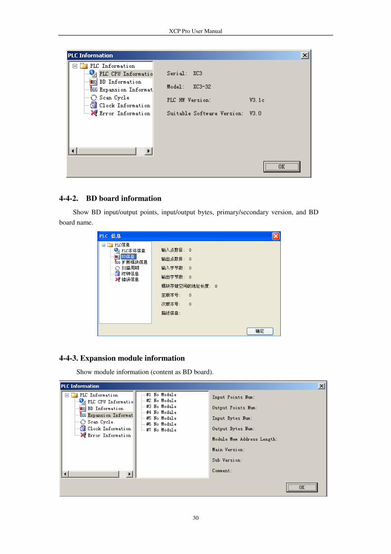
4-4-1. PLC main unit information
Show PLC series, model, slave version and befitting master version.
Method1: ① Click "Project column"→"PLC information",
a catalog will appear; ② Click "PLC main unit information","BD
board information", "expansion module
information","scan cycle","error information"
on the respective,then you can see
corresponding information.
Method 2:
Click correlative items in the left side, "Project
culumn"→ "PLC information", to view directly,
XCP Pro User Manual
30
4-4-2. BD board information
Show BD input/output points, input/output bytes, primary/secondary version, and BD
board name.
4-4-3. Expansion module information
Show module information (content as BD board).
XCP Pro User Manual
31
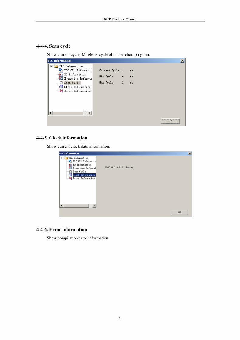
4-4-4. Scan cycle
Show current cycle, Min/Max cycle of ladder chart program.
4-4-5. Clock information
Show current clock date information.
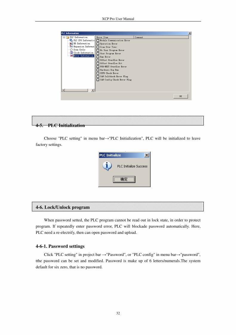
4-4-6. Error information
Show compilation error information.
XCP Pro User Manual
32
4-5. PLC Initialization
Choose "PLC setting" in menu bar→"PLC Initialization", PLC will be initialized to leave
factory settings.
4-6. Lock/Unlock program
When password setted, the PLC program cannot be read out in lock state, in order to protect
program. If repeatedly enter password error, PLC will blockade password automatically. Here,
PLC need a re-electrify, then can open password and upload.
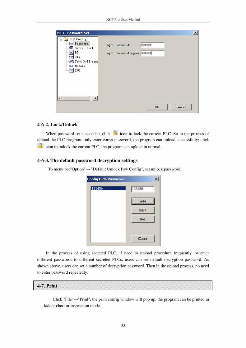
4-6-1. Password settings
Click "PLC setting" in project bar →"Password", or "PLC config" in menu bar→"password",
tthe password can be set and modified. Password is make up of 6 letters/numerals.The system
default for six zero, that is no password.
XCP Pro User Manual
33
4-6-2. Lock/Unlock
When password set succeeded, click icon to lock the current PLC. So in the process of
upload the PLC program, only enter corret password, the program can upload successfully; click
icon to unlock the current PLC, the program can upload in normal.
4-6-3. The default password decryption settings
To menu bar"Option"→ "Default Unlock Psw Config", set unlock password.
In the process of using secreted PLC, if need to upload procedure frequently, or enter
different passwords to different secreted PLCs, users can set default decryption password. As
shown above, users can set a number of decryption password. Then in the upload process, no need
to enter password repeatedly.
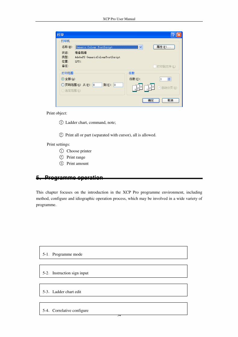
4-7. Print
Click "File"→"Print", the print config window will pop up, the program can be printed in
ladder chart or instruction mode.
XCP Pro User Manual
34
Print object: ① Ladder chart, command, note; ② Print all or part (separated with cursor), all is allowed.
Print settings: ① Choose printer ② Print range ③ Print amount
5、Programme operation
This chapter focuses on the introduction in the XCP Pro programme environment, including
method, configure and idiographic operation process, which may be involved in a wide variety of
programme.
5-1.Programme mode
5-2.Instruction sign input
5-3.Ladder chart edit
5-4.Correlative configure
XCP Pro User Manual
35
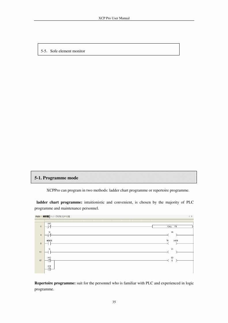
5-1. Programme mode
XCPPro can program in two methods: ladder chart programme or repertoire programme.
ladder chart programme: intuitionistic and convenient, is chosen by the majority of PLC
programme and maintenance personnel.
Repertoire programme: suit for the personnel who is familiar with PLC and experienced in logic
programme.
5-5.Sofe element monitor
XCP Pro User Manual
36
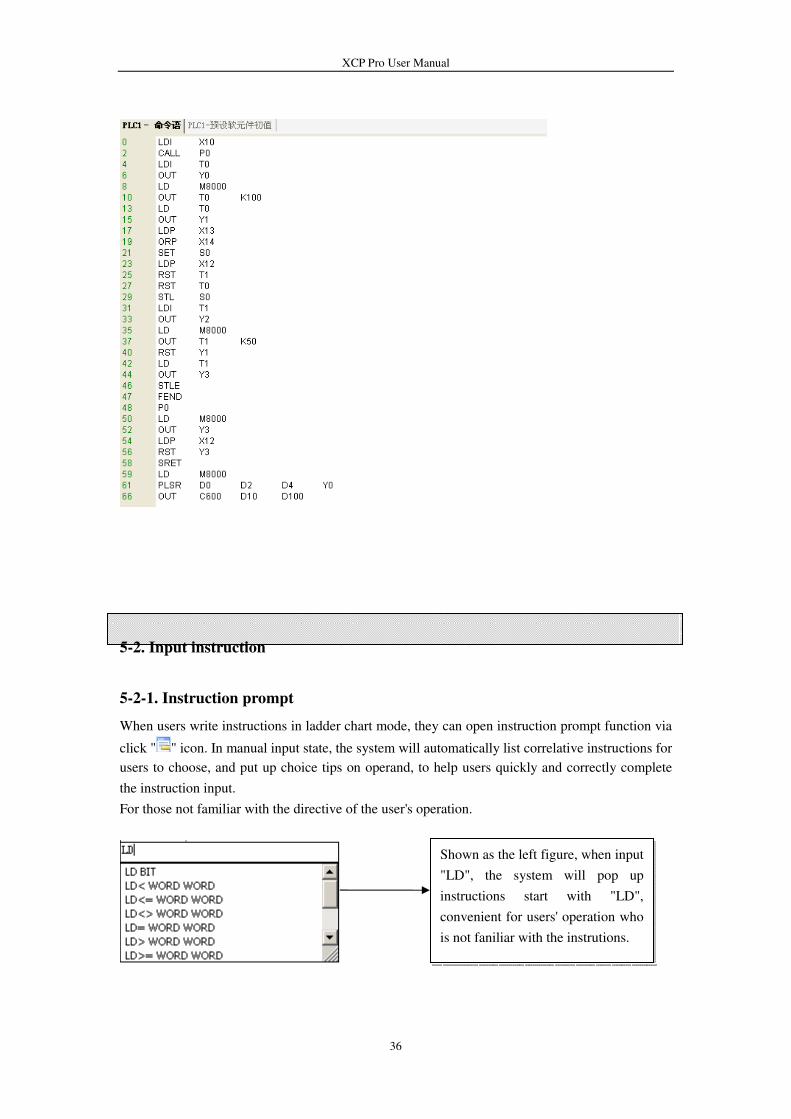
5-2. Input instruction
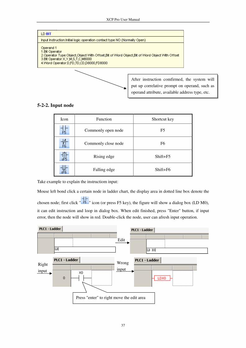
5-2-1. Instruction prompt
When users write instructions in ladder chart mode, they can open instruction prompt function via
click " " icon. In manual input state, the system will automatically list correlative instructions for
users to choose, and put up choice tips on operand, to help users quickly and correctly complete
the instruction input.
For those not familiar with the directive of the user's operation.
Shown as the left figure, when input
"LD", the system will pop up
instructions start with "LD",
convenient for users' operation who
is not faniliar with the instrutions.
XCP Pro User Manual
37
5-2-2. Input node
Take example to explain the instructiom input:
Mouse left bond click a certain node in ladder chart, the display area in dotted line box denote the
chosen node; first click " " icon (or press F5 key), the figure will show a dialog box (LD M0),
it can edit instruction and loop in dialog box. When edit finished, press "Enter" button, if input
error, then the node will show in red. Double-click the node, user can afresh input operation.
Icon Function Shortcut key
Commonly open node F5
Commonly close node F6
Rising edge Shift+F5
Falling edge Shift+F6
Edit
After instruction comfirmed, the system will
put up correlative prompt on operand, such as
operand attribute, available address type, etc.
Right
input
Wrong
input
Press "enter" to right move the edit area
XCP Pro User Manual
38
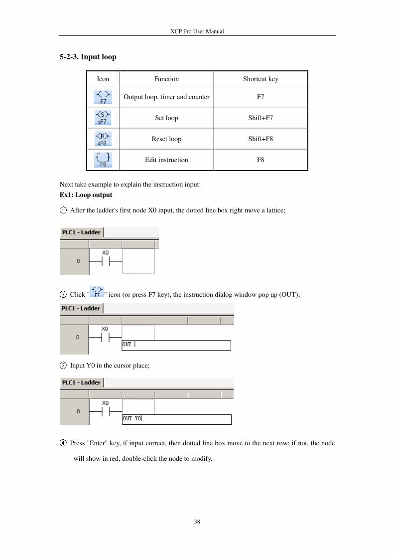
5-2-3. Input loop
Next take example to explain the instruction input:
Ex1: Loop output ① After the ladder's first node X0 input, the dotted line box right move a lattice;
② Click " " icon (or press F7 key), the instruction dialog window pop up (OUT);
③ Input Y0 in the cursor place;
④ Press "Enter" key, if input correct, then dotted line box move to the next row; if not, the node
will show in red, double-click the node to modify.
Icon Function Shortcut key
Output loop, timer and counter F7
Set loop Shift+F7
Reset loop Shift+F8
Edit instruction F8
XCP Pro User Manual
39
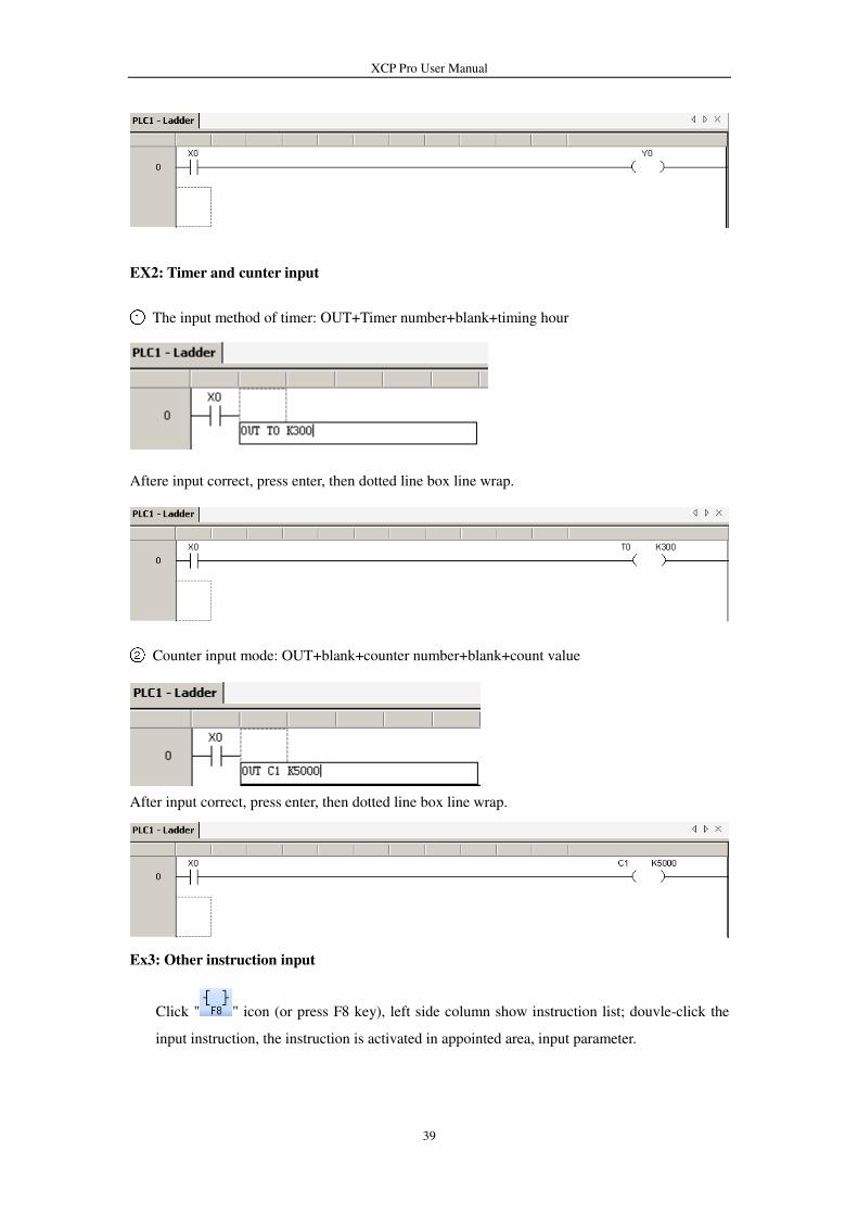
EX2: Timer and cunter input ① The input method of timer: OUT+Timer number+blank+timing hour
Aftere input correct, press enter, then dotted line box line wrap.
② Counter input mode: OUT+blank+counter number+blank+count value
After input correct, press enter, then dotted line box line wrap.
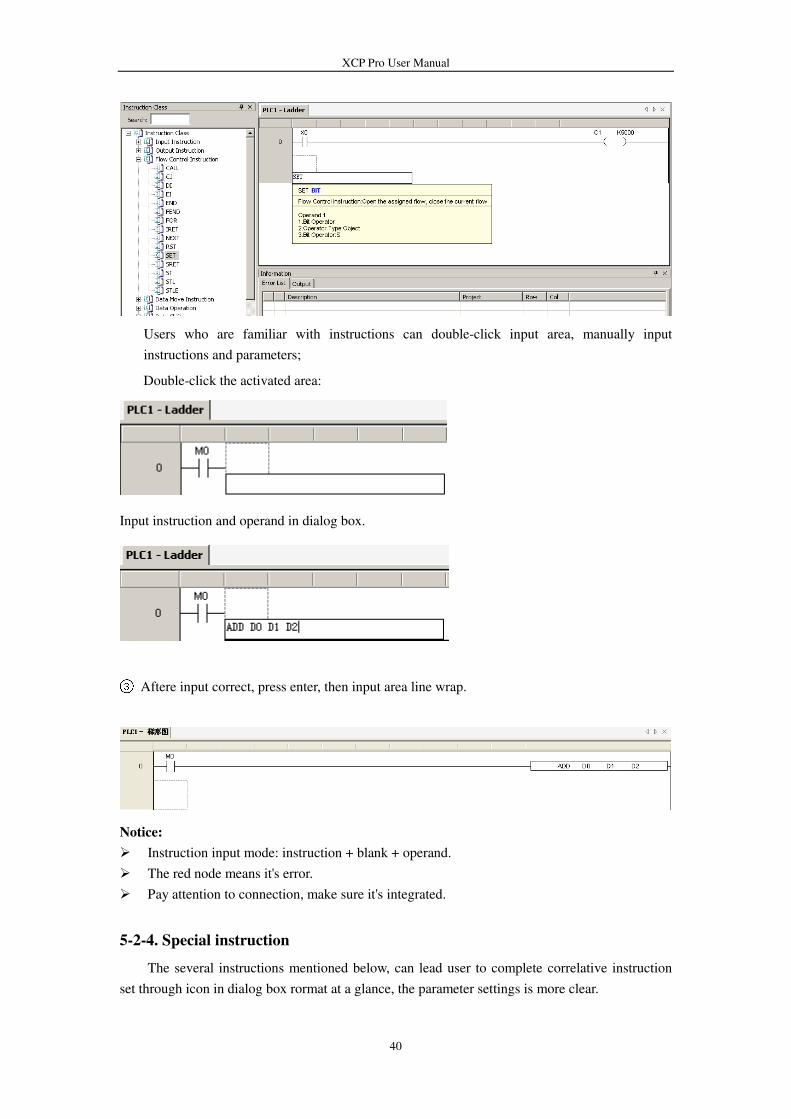
Ex3: Other instruction input
① Click " " icon (or press F8 key), left side column show instruction list; douvle-click the
input instruction, the instruction is activated in appointed area, input parameter.
XCP Pro User Manual
40
① Users who are familiar with instructions can double-click input area, manually input
instructions and parameters;
Double-click the activated area:
Input instruction and operand in dialog box.
③ Aftere input correct, press enter, then input area line wrap.
Notice:
� Instruction input mode: instruction + blank + operand.
� The red node means it's error.
� Pay attention to connection, make sure it's integrated.
5-2-4. Special instruction
The several instructions mentioned below, can lead user to complete correlative instruction
set through icon in dialog box rormat at a glance, the parameter settings is more clear.
XCP Pro User Manual
41
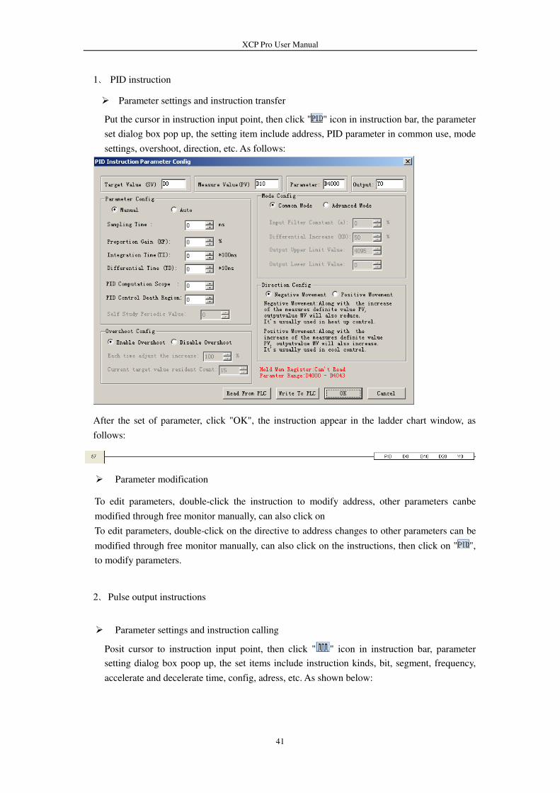
1、 PID instruction
� Parameter settings and instruction transfer
Put the cursor in instruction input point, then click " " icon in instruction bar, the parameter
set dialog box pop up, the setting item include address, PID parameter in common use, mode
settings, overshoot, direction, etc. As follows:
After the set of parameter, click "OK", the instruction appear in the ladder chart window, as
follows:
� Parameter modification
To edit parameters, double-click the instruction to modify address, other parameters canbe
modified through free monitor manually, can also click on
To edit parameters, double-click on the directive to address changes to other parameters can be
modified through free monitor manually, can also click on the instructions, then click on " ",
to modify parameters.
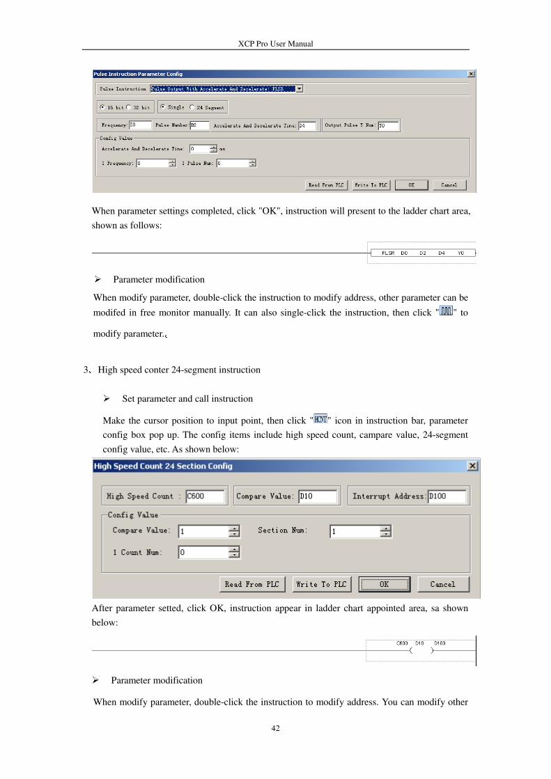
2、Pulse output instructions
� Parameter settings and instruction calling
Posit cursor to instruction input point, then click " " icon in instruction bar, parameter
setting dialog box poop up, the set items include instruction kinds, bit, segment, frequency,
accelerate and decelerate time, config, adress, etc. As shown below:
XCP Pro User Manual
42
When parameter settings completed, click "OK", instruction will present to the ladder chart area,
shown as follows:
� Parameter modification
When modify parameter, double-click the instruction to modify address, other parameter can be
modifed in free monitor manually. It can also single-click the instruction, then click " " to
modify parameter.。
3、High speed conter 24-segment instruction
� Set parameter and call instruction
Make the cursor position to input point, then click " " icon in instruction bar, parameter
config box pop up. The config items include high speed count, campare value, 24-segment
config value, etc. As shown below:
After parameter setted, click OK, instruction appear in ladder chart appointed area, sa shown
below:
� Parameter modification
When modify parameter, double-click the instruction to modify address. You can modify other
XCP Pro User Manual
43
parameter via free monitor manually, and also can click the instruction first, then click " " to
modify parameter.
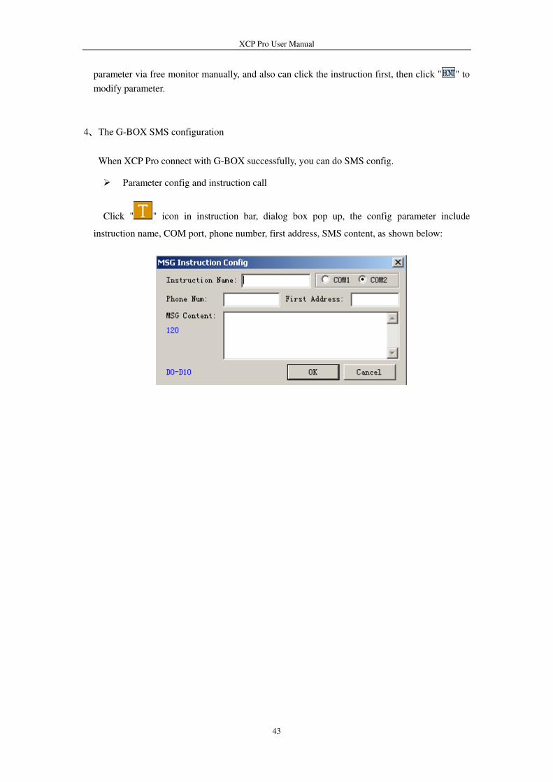
4、The G-BOX SMS configuration
When XCP Pro connect with G-BOX successfully, you can do SMS config.
� Parameter config and instruction call
Click " " icon in instruction bar, dialog box pop up, the config parameter include
instruction name, COM port, phone number, first address, SMS content, as shown below:
XCP Pro User Manual
44
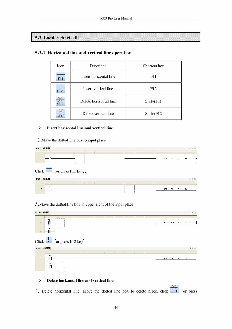
5-3. Ladder chart edit
5-3-1. Horizontal line and vertical line operation
� Insert horizontal line and vertical line ① Move the dotted line box to input place
Click (or press F11 key)。
②Move the dotted line box to upper right of the input place
Click (or press F12 key)
� Delete horizontal line and vertical line ① Delete horizontal line: Move the dotted line box to delete place, click (or press
Icon Functions Shortcut key
Insert horizontal line F11
Insert vertical line F12
Delete horizontal line Shift+F11
Delete vertical line Shift+F12
XCP Pro User Manual
45
Shift+F11 key). ② Delete vertical line: Move the dotted line box to upper right of the delete place, click (or
press Shift+F12 key).
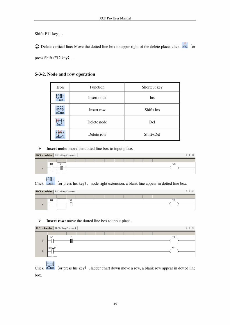
5-3-2. Node and row operation
� Insert node: move the dotted line box to input place.
Click (or press Ins key),node right extension, a blank line appear in dotted line box.
� Insert row: move the dotted line box to input place.
Click (or press Ins key), ladder chart down move a row, a blank row appear in dotted line
box.
Icon Function Shortcut key
Insert node Ins
Insert row Shift+Ins
Delete node Del
Delete row Shift+Del
XCP Pro User Manual
46
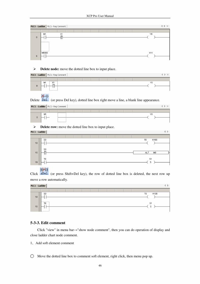
� Delete node: move the dotted line box to input place.
Delete (or press Del key), dotted line box right move a line, a blank line appearance.
� Delete row: move the dotted line box to input place.
Click (or press Shift+Del key), the row of dotted line box is deleted, the next row up
move a row automatically.
5-3-3. Edit comment
Click "view" in menu bar→"show node comment", then you can do operation of display and
close ladder chart node comment.
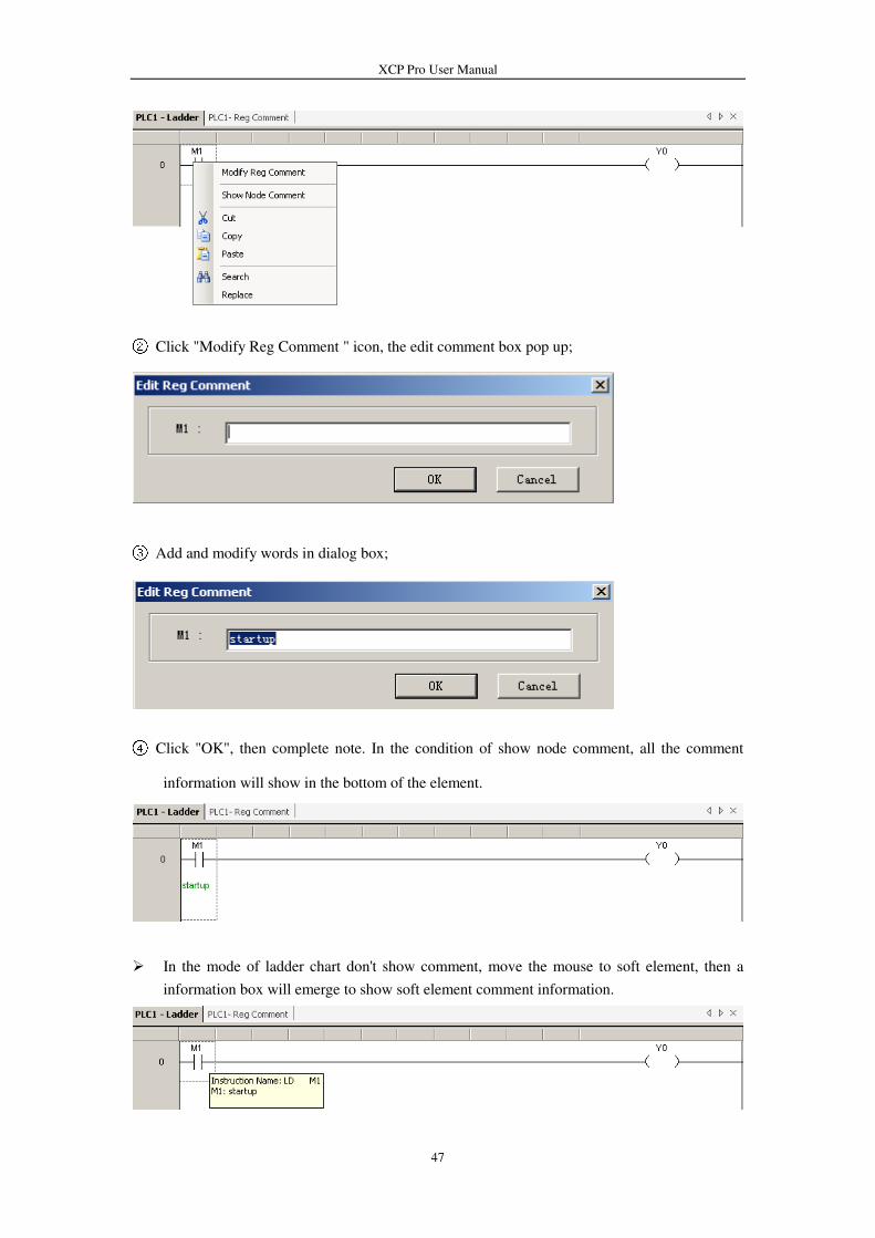
1、Add soft element comment ① Move the dotted line box to comment soft element, right click, then menu pop up.
XCP Pro User Manual
47
② Click "Modify Reg Comment " icon, the edit comment box pop up;
③ Add and modify words in dialog box;
④ Click "OK", then complete note. In the condition of show node comment, all the comment
information will show in the bottom of the element.
� In the mode of ladder chart don't show comment, move the mouse to soft element, then a
information box will emerge to show soft element comment information.
XCP Pro User Manual
48
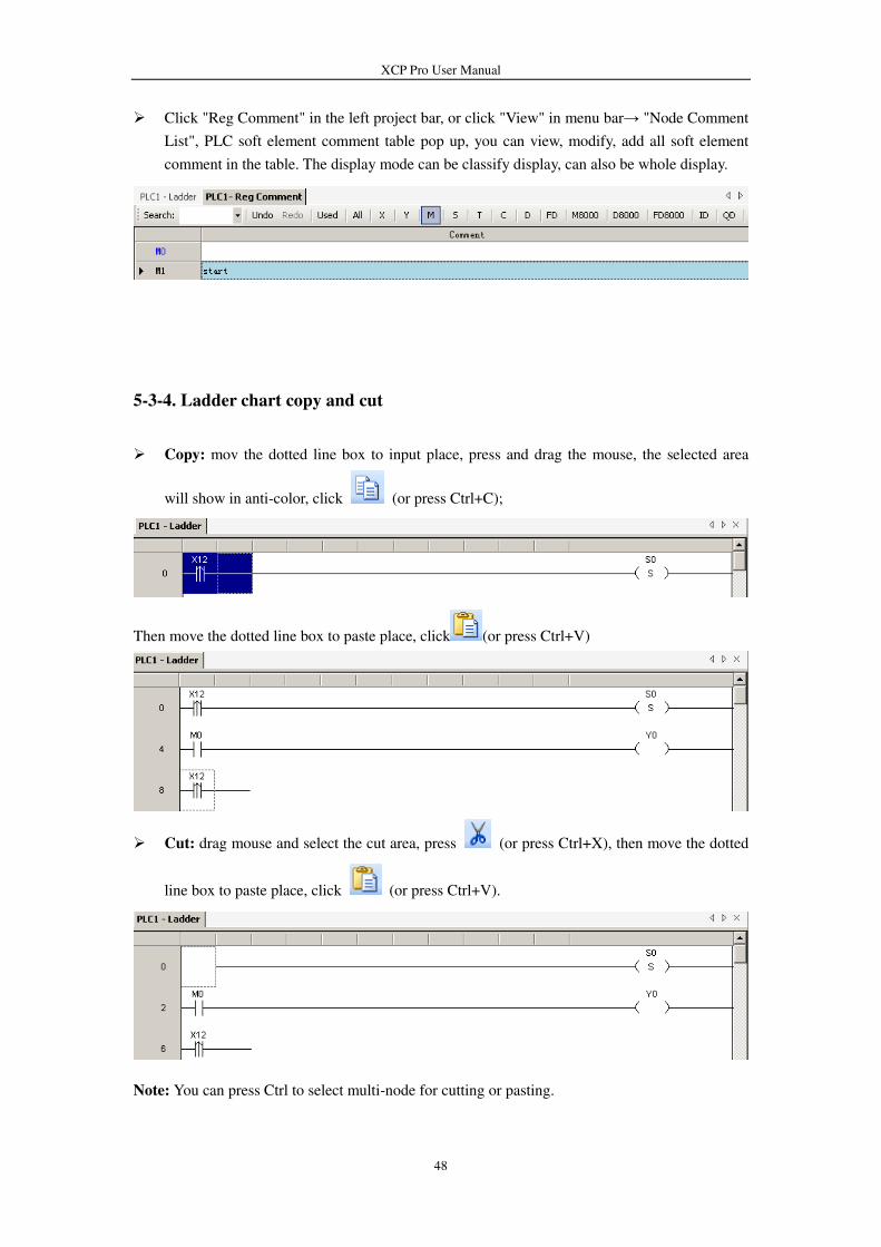
� Click "Reg Comment" in the left project bar, or click "View" in menu bar→ "Node Comment
List", PLC soft element comment table pop up, you can view, modify, add all soft element
comment in the table. The display mode can be classify display, can also be whole display.
5-3-4. Ladder chart copy and cut
� Copy: mov the dotted line box to input place, press and drag the mouse, the selected area
will show in anti-color, click (or press Ctrl+C);
Then move the dotted line box to paste place, click (or press Ctrl+V)
� Cut: drag mouse and select the cut area, press (or press Ctrl+X), then move the dotted
line box to paste place, click (or press Ctrl+V).
Note: You can press Ctrl to select multi-node for cutting or pasting.
XCP Pro User Manual
49
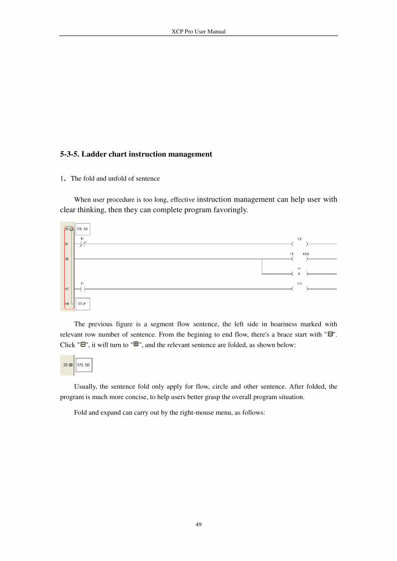
5-3-5. Ladder chart instruction management
1、The fold and unfold of sentence
When user procedure is too long, effective instruction management can help user with
clear thinking, then they can complete program favoringly.
The previous figure is a segment flow sentence, the left side in hoariness marked with
relevant row number of sentence. From the begining to end flow, there's a brace start with " ".
Click " ", it will turn to " ", and the relevant sentence are folded, as shown below:
Usually, the sentence fold only apply for flow, circle and other sentence. After folded, the
program is much more concise, to help users better grasp the overall program situation.
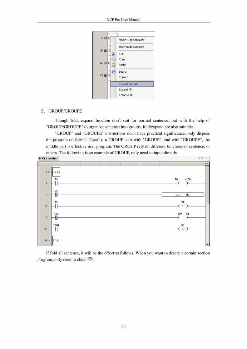
Fold and expand can carry out by the right-mouse menu, as follows:
XCP Pro User Manual
50
2、 GROUP/GROUPE
Though fold, expand function don't suit for normal sentence, but with the help of
"GROUP/GROUPE" to organize sentence into groups, fold/expand are also suitable.
"GROUP" and "GROUPE" instructions don't have practical significance, only dispose
the program on formal. Usually, a GROUP start with "GROUP", end with "GROUPE", the
middle part is effective user program. The GROUP rely on different functions of sentence, or
others. The following is an example of GROUP, only need to input directly.
If fold all sentence, it will be the effect as follows. When you want to descry a certain section
program, only need to click " ".
XCP Pro User Manual
51
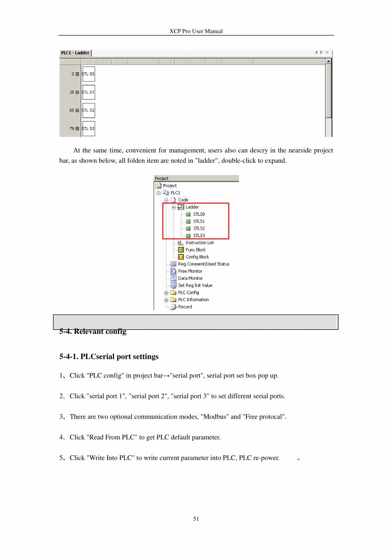
At the same time, convenient for management, users also can descry in the nearside project
bar, as shown below, all folden item are noted in "ladder", double-click to expand.
5-4. Relevant config
5-4-1. PLCserial port settings
1、Click "PLC config" in project bar→"serial port", serial port set box pop up.
2、Click "serial port 1", "serial port 2", "serial port 3" to set different serial ports.
3、There are two optional communication modes, "Modbus" and "Free protocal".
4、Click "Read From PLC" to get PLC default parameter.
5、Click "Write Into PLC" to write current parameter into PLC, PLC re-power. 。

XCP Pro User Manual
52
5-4-2. Password settings
Click "PLC Config" in project bar→"Password", password set box pop up for password
setting and modification, work toghter with lock/unlock functions.
Modbus
communication
Free protocal
communication
XCP Pro User Manual
53
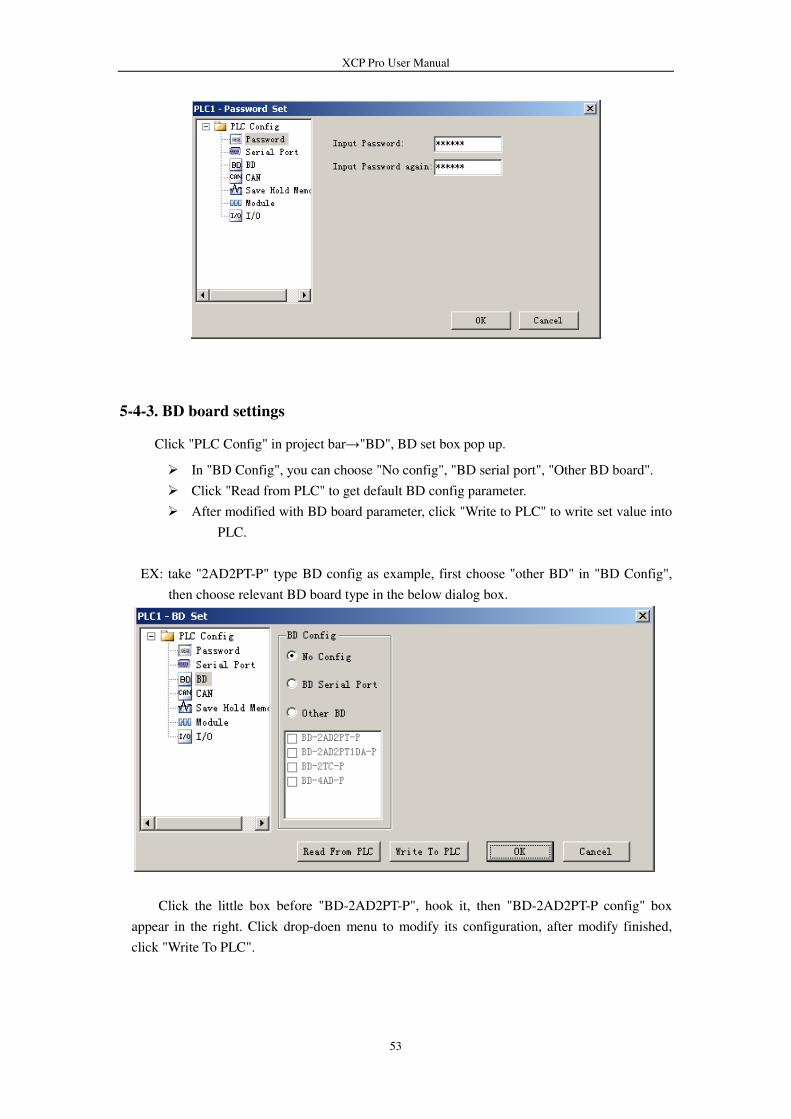
5-4-3. BD board settings
Click "PLC Config" in project bar→"BD", BD set box pop up.
� In "BD Config", you can choose "No config", "BD serial port", "Other BD board".
� Click "Read from PLC" to get default BD config parameter.
� After modified with BD board parameter, click "Write to PLC" to write set value into
PLC.
EX: take "2AD2PT-P" type BD config as example, first choose "other BD" in "BD Config",
then choose relevant BD board type in the below dialog box.
Click the little box before "BD-2AD2PT-P", hook it, then "BD-2AD2PT-P config" box
appear in the right. Click drop-doen menu to modify its configuration, after modify finished,
click "Write To PLC".
XCP Pro User Manual
54
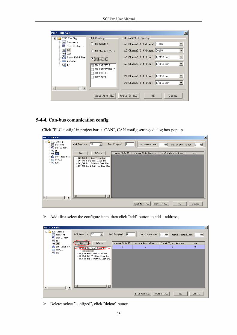
5-4-4. Can-bus comunication config
Click "PLC config" in project bar→"CAN", CAN config settings dialog box pop up.
� Add: first select the configure item, then click "add" button to add address;
� Delete: select "configed", click "delete" button.
XCP Pro User Manual
55
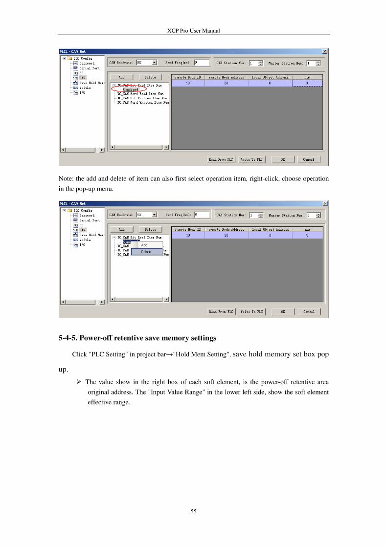
Note: the add and delete of item can also first select operation item, right-click, choose operation
in the pop-up menu.
5-4-5. Power-off retentive save memory settings
Click "PLC Setting" in project bar→"Hold Mem Setting", save hold memory set box pop
up.
� The value show in the right box of each soft element, is the power-off retentive area
original address. The "Input Value Range" in the lower left side, show the soft element
effective range.
XCP Pro User Manual
56
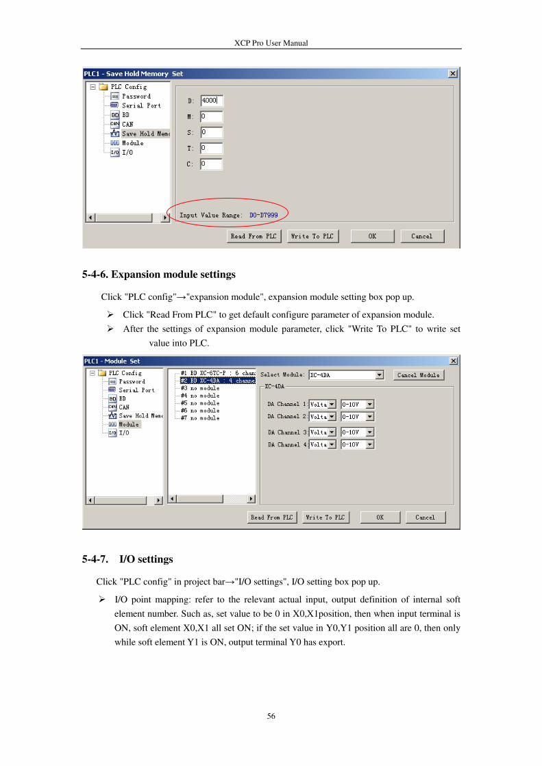
5-4-6. Expansion module settings
Click "PLC config"→"expansion module", expansion module setting box pop up.
� Click "Read From PLC" to get default configure parameter of expansion module.
� After the settings of expansion module parameter, click "Write To PLC" to write set
value into PLC.
5-4-7. I/O settings
Click "PLC config" in project bar→"I/O settings", I/O setting box pop up.
� I/O point mapping: refer to the relevant actual input, output definition of internal soft
element number. Such as, set value to be 0 in X0,X1position, then when input terminal is
ON, soft element X0,X1 all set ON; if the set value in Y0,Y1 position all are 0, then only
while soft element Y1 is ON, output terminal Y0 has export.
XCP Pro User Manual
57
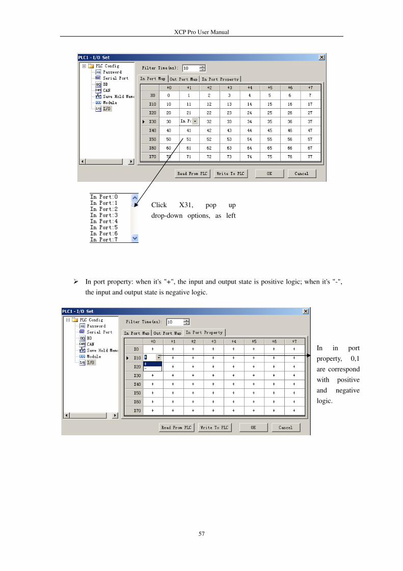
� In port property: when it's "+", the input and output state is positive logic; when it's "-",
the input and output state is negative logic.
Click X31, pop up
drop-down options, as left
In in port
property, 0,1
are correspond
with positive
and negative
logic.
XCP Pro User Manual
58
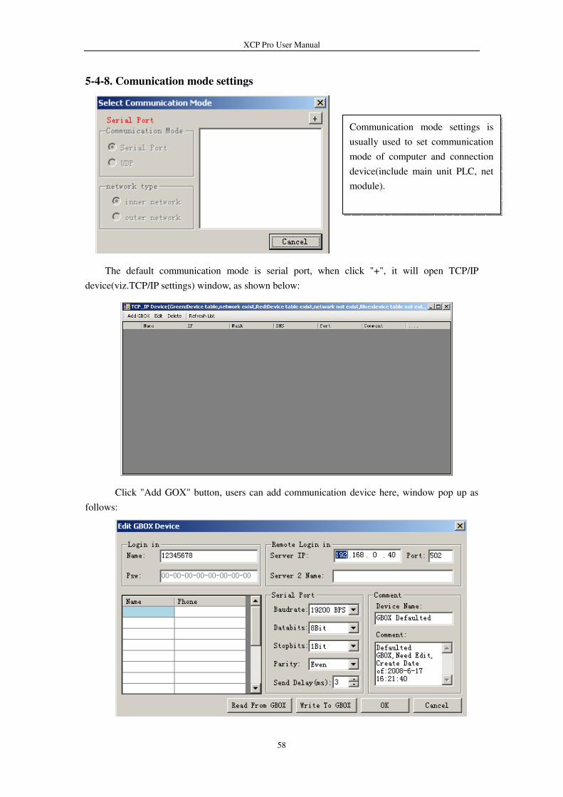
5-4-8. Comunication mode settings
The default communication mode is serial port, when click "+", it will open TCP/IP
device(viz.TCP/IP settings) window, as shown below:
Click "Add GOX" button, users can add communication device here, window pop up as
follows:
Communication mode settings is
usually used to set communication
mode of computer and connection
device(include main unit PLC, net
module).
XCP Pro User Manual
59
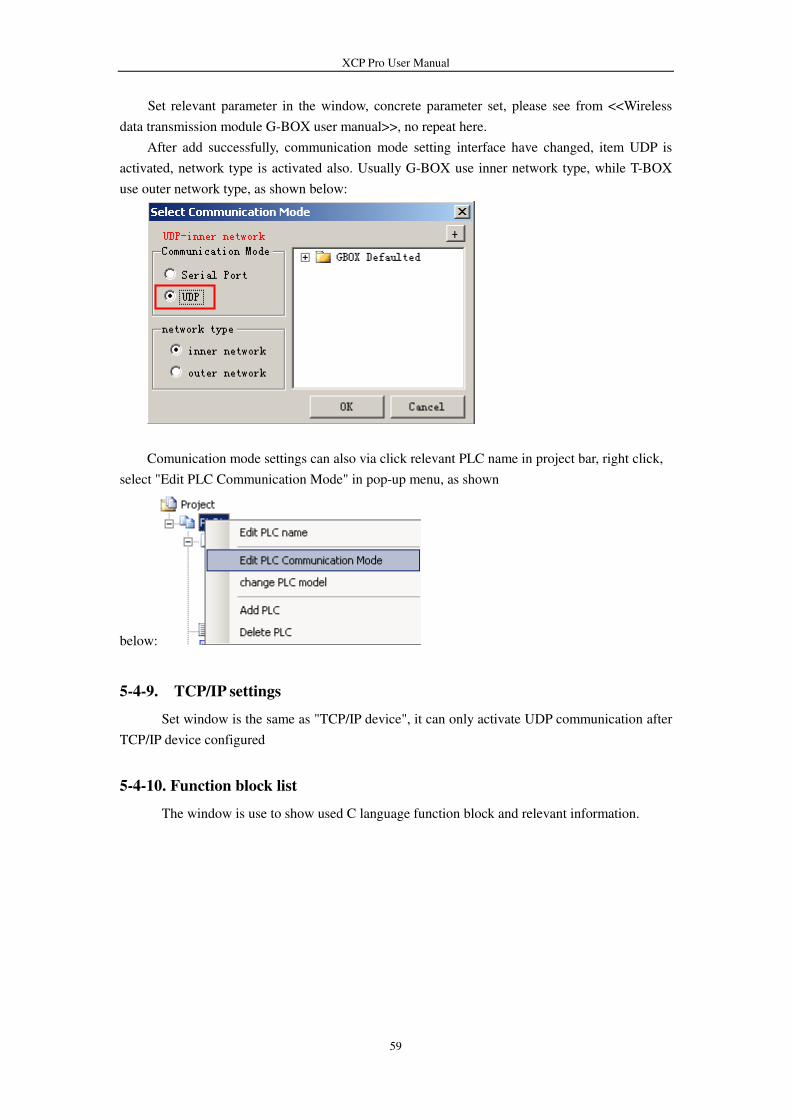
Set relevant parameter in the window, concrete parameter set, please see from <<Wireless
data transmission module G-BOX user manual>>, no repeat here.
After add successfully, communication mode setting interface have changed, item UDP is
activated, network type is activated also. Usually G-BOX use inner network type, while T-BOX
use outer network type, as shown below:
Comunication mode settings can also via click relevant PLC name in project bar, right click,
select "Edit PLC Communication Mode" in pop-up menu, as shown
below:
5-4-9. TCP/IP settings
Set window is the same as "TCP/IP device", it can only activate UDP communication after
TCP/IP device configured
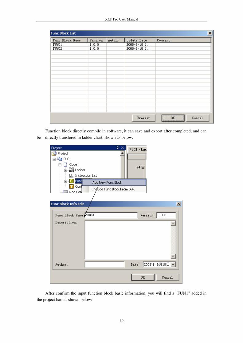
5-4-10. Function block list
The window is use to show used C language function block and relevant information.
XCP Pro User Manual
60
Function block directly compile in software, it can save and export after completed, and can
be directly transfered in ladder chart, shown as below:
After confirm the input function block basic information, you will find a "FUN1" added in
the project bar, as shown below:
XCP Pro User Manual
61
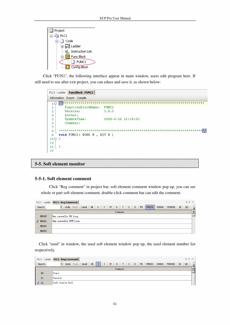
Click "FUN1", the following interface appear in main window, users edit program here. If
still need to use after exit project, you can educe and save it, as shown below:
5-5. Soft element monitor
5-5-1. Soft element comment
Click "Reg comment" in project bar, soft element comment window pop up, you can see
whole or part soft element comment, double-click comment bar can edit the comment.
Click "used" in window, the used soft element window pop up, the used element number list
respectively.
XCP Pro User Manual
62
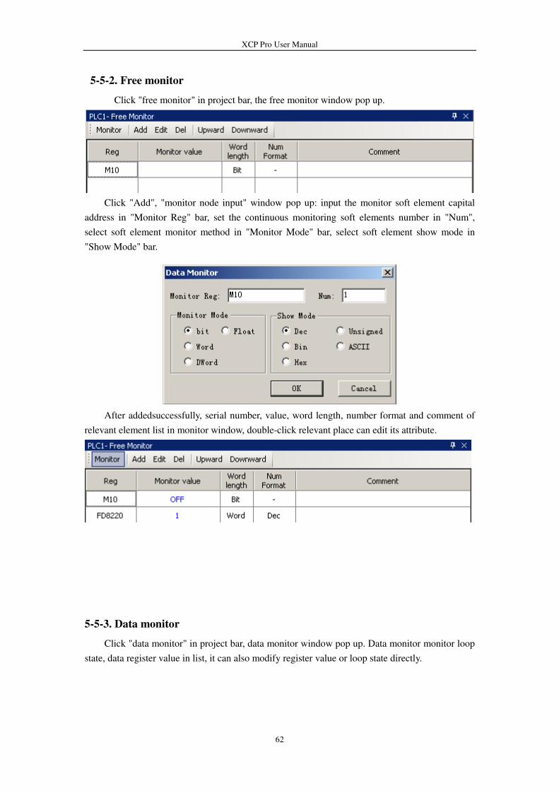
5-5-2. Free monitor
Click "free monitor" in project bar, the free monitor window pop up.
Click "Add", "monitor node input" window pop up: input the monitor soft element capital
address in "Monitor Reg" bar, set the continuous monitoring soft elements number in "Num",
select soft element monitor method in "Monitor Mode" bar, select soft element show mode in
"Show Mode" bar.
After addedsuccessfully, serial number, value, word length, number format and comment of
relevant element list in monitor window, double-click relevant place can edit its attribute.
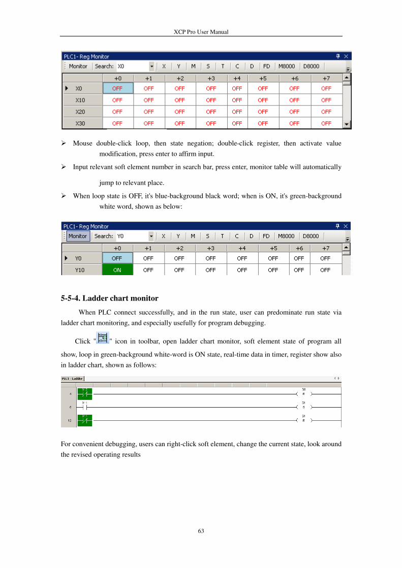
5-5-3. Data monitor
Click "data monitor" in project bar, data monitor window pop up. Data monitor monitor loop
state, data register value in list, it can also modify register value or loop state directly.
XCP Pro User Manual
63
� Mouse double-click loop, then state negation; double-click register, then activate value
modification, press enter to affirm input.
� Input relevant soft element number in search bar, press enter, monitor table will automatically
jump to relevant place.
� When loop state is OFF, it's blue-background black word; when is ON, it's green-background
white word, shown as below:
5-5-4. Ladder chart monitor
When PLC connect successfully, and in the run state, user can predominate run state via
ladder chart monitoring, and especially usefully for program debugging.
Click " " icon in toolbar, open ladder chart monitor, soft element state of program all
show, loop in green-background white-word is ON state, real-time data in timer, register show also
in ladder chart, shown as follows:
For convenient debugging, users can right-click soft element, change the current state, look around
the revised operating results
XCP Pro User Manual
64
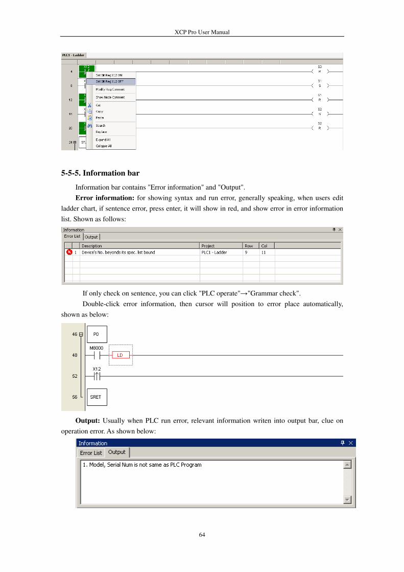
5-5-5. Information bar
Information bar contains "Error information" and "Output".
Error information: for showing syntax and run error, generally speaking, when users edit
ladder chart, if sentence error, press enter, it will show in red, and show error in error information
list. Shown as follows:
If only check on sentence, you can click "PLC operate"→"Grammar check".
Double-click error information, then cursor will position to error place automatically,
shown as below:
Output: Usually when PLC run error, relevant information writen into output bar, clue on
operation error. As shown below:
XCP Pro User Manual
65
The display of information, data monitor and free monitor can switch via button in below of
window, shown as below:
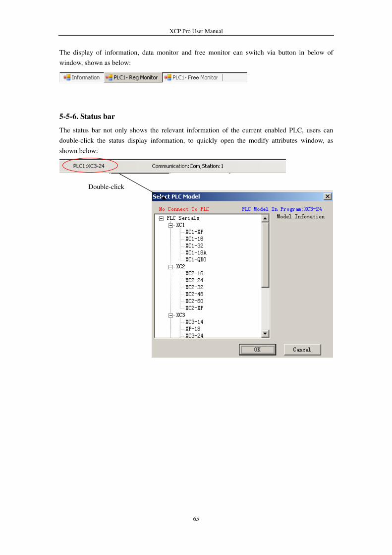
5-5-6. Status bar
The status bar not only shows the relevant information of the current enabled PLC, users can
double-click the status display information, to quickly open the modify attributes window, as
shown below:
Double-click

XCP Pro User Manual
信捷科技电子有限公司 江苏省无锡市蠡园开发区 创意产业园 7号楼四楼 邮编: 214072 电话: (0510)85134136 传真: (0510)85111290
Xinje Electronic Co., Ltd.
4th Floor Building 7,Orignality Industry
park, Liyuan Development Zone, Wuxi
City, Jiangsu Province 214072
Tel: (510)85134136
Fax: (510)85111290