X-shooter: Backbone and UV-Blue and Visible spectrographs ... · X-shooter: Backbone and UV-Blue...
13
X-shooter: Backbone and UV-Blue and Visible spectrographs. Final AIV and Measured Performance. Per Kjærgaard Rasmussen a , Filippo M. Zerbi b,c , Hans Dekker c , Joel Vernet c , Jeppe J. Andersen a , Vincenzo De Caprio d , Paolo Dimarcantonio e , Sandro D’Odorico c , Jean-Louis Lizon c , Christian Lucuix c , Niels Michaelsen a , Emilio Molinari b , Preben Nørregaard a , Alberto Riva b , Marco Riva b , Paolo Santin e , Anton N. Sørensen a , Paolo Spanò b , Dennis Wistisen a , a Niels Bohr Institute, Juliane Maries Vej 30, 2100 Copenhagen - Denmark b INAF Osservatorio Astronomico di Brera, Via E. Bianchi 46, 23807 Merate (LC) - Italy c European Southern Observatory, Karl-Schwarzschild-Str. 2, 85748 Garching b. München - Germany d INAF – IASF, Instituto di Astrofisica Spazialoe e Fisica Cosmica, Via E. Bassini 15, 20133 Milano - Italy e INAF Osservatorio Astronomico di Trieste, Via Tiepolo 11, 34143 Trieste - Italy ABSTRACT X-shooter is a wide band (U to K) intermediate resolution (4000-14000) single object three-arms spectrograph for the VLT. Currently in the last phase of integration, X-shooter will see the first light at ESO Paranal as the first of the VLT second generation instruments in the last quarter of 2008. We describe in this paper the final steps in the integration and testing phase of the central Backbone with its key functions (including the active flexure compensation mirrors) and of the two UV-Blue and Visible spectroscopic arms. We report on the stability results of the preslit optics and of the spectrographs and on the remarkable efficiency which is derived from the measurements of the optical components of the instrument. Keywords: ESO VLT, medium resolution spectrograph, faint object spectroscopy 1-INTRODUCTION X-shooter is a single object medium resolution spectrograph for the VLT aimed at the highest possible efficiency. The instrument will be mounted at the Cassegrain focus and consists of three individual spectrographs covering the UV-blue (UVB), visible (VIS) and near infrared region (from 330nm to 2.4 μm) mounted on a common “Backbone” structure. The optical design for all spectrographs is the so-called 4C design, and is described in an earlier paper 1 . A Figure 1 Functional diagram of X-shooter Table 1 – X-shooter Main Characteristics Spectral format: Prism cross-dispersed echelle Wavelength range: 300-2400nm split in 3 arms, UVB: 300-550nm, VIS: 550-1000nm, NIR: 1000-2400nm Spectral resolution (1” slit): UVB and NIR: 5000, VIS: 7000 Std. Slits: 0.4”-1.5” x 11” IFU: 4 x 1.8” input area, 12 x 0.6” exit slit (3 slices) Detectors: UVB: 2kx4k E2V, VIS: 2kx4k MIT/LL NIR: 2kx2k Rockwell Hawaii2RG MBE (used area 1kx1k) Auxiliary Functions: Calibration unit, Acquisition camera (1.5’x1.5’), ADC for UVB and VIS, Automatic Flexure Compensating System
Transcript of X-shooter: Backbone and UV-Blue and Visible spectrographs ... · X-shooter: Backbone and UV-Blue...
X-shooter: Backbone and UV-Blue and Visible spectrographs. Final AIV and Measured Performance.
Per Kjærgaard Rasmussena, Filippo M. Zerbib,c, Hans Dekkerc, Joel Vernetc, Jeppe J. Andersena, Vincenzo De Capriod, Paolo Dimarcantonioe, Sandro D’Odoricoc, Jean-Louis Lizonc, Christian Lucuixc, Niels Michaelsena, Emilio Molinarib, Preben Nørregaarda, Alberto Rivab, Marco Rivab,
Paolo Santine, Anton N. Sørensena, Paolo Spanòb, Dennis Wistisena,
aNiels Bohr Institute, Juliane Maries Vej 30, 2100 Copenhagen - Denmark bINAF Osservatorio Astronomico di Brera, Via E. Bianchi 46, 23807 Merate (LC) - Italy
cEuropean Southern Observatory, Karl-Schwarzschild-Str. 2, 85748 Garching b. München - Germany
dINAF – IASF, Instituto di Astrofisica Spazialoe e Fisica Cosmica, Via E. Bassini 15, 20133 Milano - Italy
eINAF Osservatorio Astronomico di Trieste, Via Tiepolo 11, 34143 Trieste - Italy
ABSTRACT
X-shooter is a wide band (U to K) intermediate resolution (4000-14000) single object three-arms spectrograph for the VLT. Currently in the last phase of integration, X-shooter will see the first light at ESO Paranal as the first of the VLT second generation instruments in the last quarter of 2008. We describe in this paper the final steps in the integration and testing phase of the central Backbone with its key functions (including the active flexure compensation mirrors) and of the two UV-Blue and Visible spectroscopic arms. We report on the stability results of the preslit optics and of the spectrographs and on the remarkable efficiency which is derived from the measurements of the optical components of the instrument. Keywords: ESO VLT, medium resolution spectrograph, faint object spectroscopy
1-INTRODUCTION X-shooter is a single object medium resolution spectrograph for the VLT aimed at the highest possible efficiency. The instrument will be mounted at the Cassegrain focus and consists of three individual spectrographs covering the UV-blue (UVB), visible (VIS) and near infrared region (from 330nm to 2.4 µm) mounted on a common “Backbone” structure. The optical design for all spectrographs is the so-called 4C design, and is described in an earlier paper1. A
Figure 1 Functional diagram of X-shooter
Table 1 – X-shooter Main Characteristics Spectral format: Prism cross-dispersed echelle Wavelength range: 300-2400nm split in 3 arms, UVB: 300-550nm, VIS: 550-1000nm, NIR: 1000-2400nm Spectral resolution (1” slit): UVB and NIR: 5000, VIS: 7000 Std. Slits: 0.4”-1.5” x 11” IFU: 4 x 1.8” input area, 12 x 0.6” exit slit (3 slices) Detectors: UVB: 2kx4k E2V, VIS: 2kx4k MIT/LL NIR: 2kx2k Rockwell Hawaii2RG MBE (used area 1kx1k) Auxiliary Functions: Calibration unit, Acquisition camera (1.5’x1.5’), ADC for UVB and VIS, Automatic Flexure Compensating System

prism cross dispersed echelle spectral format is used for all three spectrographs. The Backbone houses all common functions like splitting the light (using dichroics), the calibration system, the atmospheric dispersion correctors (ADCs), the active flexure compensation system (AFC), and the target acquisition. An Integral Field Unit, which will be described in a separate paper, is also available in the Backbone. The instrument has been built by ESO and four national partners (Denmark, France, Italy, and the Netherlands), who contributed the larger fraction of the hardware and software of the instrument covering the direct costs and the FTEs. A functional diagram of X-shooter is shown in Figure 1, the main characteristics are given in Table 1. The project has been described earlier, see the papers from the 2006 SPIE meeting on astronomical instrumentation2,3 and also some more recent papers, focusing on the more recent development and on the expected performance4,5. The current status is that ESO has now accepted and received the integrated and well tested subunits (Backbone and spectrographs). Final integration is now ongoing at ESO. The two CCD detectors for the UVB and VIS spectrographs have been installed and tested. Also the infrared Rockwell Hawaii2 detector has been installed and tested. Sample spectra have been obtained in all three arms, and performance in terms of spectral resolution, efficiency, stability, and flexure has been measured. The instrument is scheduled for first light at a unit VLT telescope in the 4th quarter of 2008. After a further commissioning the instrument is expected to be released for the common user around May 2009.
Figure 2 X-Shooter mounted on the VLT telescope simulator at ESO.
VIS Spectrograph NIR Spectrograph
UVB Spectrograph Top ring
Electronics cabinets Backbone
Electronics cabinets

The fully cryogenic infrared spectrograph will be described in a separate SPIE paper. In parallel with the mentioned hardware the instrument control electronics and the instrument control SW was developed and tested. Finally also an advanced data reduction pipeline has been developed which delivers a fully reduced and calibrated one-dimensional as well as a 2-d spectrum. The reduction pipeline is based on a physical model of the spectrograph6.
2-INSTRUMENT OVERVIEW 2.1 The Backbone
The focal plane of the VLT falls inside the Backbone. Here the so-called Acquisition and Guide unit is placed where the light can be directed to the Acquisition and Guiding camera or passed on to the Preslit Optical Table. In this latter unit the light is directed into the three spectrographs via dichroics and folding mirrors. The folding mirrors are mounted on piezo driven tip-tilt tables from Physik Instrumente, which is the heart of the active flexure compensating system. After the light is split for the UVB and VIS arms, it passes the ADCs and the preslit re-imaging optics, manufactured by Winlight Systems, which converts the VLTs F/13.4 beam to the F/6.5 beams feeding the two optical spectrographs. The calibration system comes in two parts: two units on the side of the Backbone housing different light sources and a unit in front of the A&G system (before the focal plan) housing a shutter and a carriage with mirrors directing the light into the instrument.
Acquisition & Guiding System
The mode of operation of the Acquisition and Guiding (A&G) System is determined by a slide moving across the telescope focal plane. The slide carries the Integral Field Unit, a downward-looking pellicle and a 45 degree mirror. Via the mirror, the A&G System re-images the telescope focal plane onto an ESO NTCCD camera. The mirror has three positions, one reflecting the full 90x90 arcsecond field for acquisition, one with a 15x10 arcsecond slot allowing field viewing during spectrosopy and the last position having a 0.5 arcsecond / 0.25mm pinhole as an alignment reference. The challenge of producing this special mirror was accepted by Kugler GmbH. The mirror substrate is aluminium, machined to a flatness of <160nm over 20mm and a Ra < 6nm. The pellicle allows imaging of the individual spectrograph slits by selecting an appropriate filter. In addition, viewing the pupil stops and the surface of the first dichroic is possible by inserting a stacked lens and filter into the filter wheel. The lenses for the A&G camera and auxiliary functions were manufactured and coated by SESO. The filter wheel of the A&G camera has 12 positions, which are filled by a Bessel set from Chroma Technology Corp. and a SDSS set manufactured by Asahi Spectra Co. The A&G system resides on a dedicated platform, which allowed the first phase of the AIT to be performed outside the backbone.
Figure 3 The Pre-slit Optical Table during AIT. The dichroic box in the center is surrounded by folding mirrors and the ADC units on both sides. The A&G table with TCCD camera and filter-wheel is visible above.

Figure 4 The backbone during AIT. Positioned in horizontal orientation on a rolling carriage, this allowed easy access to all sides and testing of flexure at maximum Zenith distance. Autocollimator towers are mounted for definition of the axes.
2.2 The UVB and VIS Spectrographs
The UVB and VIS spectrographs are very similar as regards volumes and deployment of the element. They are built according to the same scheme of the 4C optical design, with the optimization for the wavelength regime obtained using different materials and coatings. Such a similarity prompted for a parallel development of the mechanical design aimed to use as much as possible identical components and solutions.
.
Figure 5 The optical layout of the VIS spectrograph.
Alignment
A rough outline of the alignment process starts with a mechanical definition of the telescope focal plane with respect to the VLT mounting flange. This is followed by establishing the optical axis using an auto-collimating telescope and precisely located towers locating the spectrograph slit planes. The dichroics and folding mirrors were aligned using first a laser roughly co-aligned with the optical axis, followed by using the autocollimator. After this, the ADC units were inserted and aligned. The A&G table could now be installed in the backbone, with special attention to matching the reference pinhole postion to the optical axis and focal plane. Finally, the calibration system is inserted, with lamp units and stops on the outside of the backbone and pupil imagers inside.

The Benches The benches of the UV and VIS spectrographs are almost identical. A bench consists of two main parts which both are made in aluminum (AlMg4.5Mn). The first part is the bottom plate, which is milled out of one piece. This part contains the mounting interface to the Backbone on the one side, and provides the mounting bench on the other side for most of the optical supports. The second part of the bench is a box structure with two internal walls and a cylindrical piece with the mounting flange for the CCD cryostat. One of the walls carry the holder for the main mirror, the other wall stiffens the structure at the cylindrical piece. The second part is welded together. The two parts are bolted and glued together before the final milling of the internal surfaces. The overall dimensions of the benches are (WxHxD) 1300x580x450 mm. The wall thickness is designed to be 12 mm all over and the weight of the whole structure is about 125 kg. Basically each bench is mounted directly on the sides of the Backbone by three M 16 bolts. A fourth point is added in form of a Ø12mm aluminum rod placed where the gravitational induced stress is highest. Three adjustable hard points on the bench with mating reference points on the Backbone ensures the reference between the bench and the Backbone.
Figure 6 Left: The two spectrograph benches. Right: the two parts of the bench mentioned in the text.
The Optics Spectrograph optics (mirrors, corrector lenses, prisms, cameras) have been manufactured by Winlight System (France), together with optical components of the preslit arms. The diffraction gratings have been mastered and replicated onto Zerodur substrates by Newport, Inc. (US). After manufacturing and preliminary tests done in the workshop, all components have been functionally testes in Merate and in Copenhagen for final acceptance, to check both optical and mechanical performances (e.g., mechanical stability for the atmospheric dispersion corrector). Optical performances like wavefront errors were tested with a phase-shifting interferometer, while efficiencies on some components (mirrors, gratings) have been measured with a suited setup of a spectrophotometer. All measurements were found in agreement with the test results at the factory.
The Optics Mechanical Supports
With few exceptions the mechanical supports for the optics follow a single concept, customized for the specific need, already described in details in [2]. The support consists in a pad (invar or steel according to the specific application) glued on the optical component and dynamically coupled with an aluminum frame connected to the instrument bench.

Figure 7: The interferometric setup for the spectrograph main mirror (left) and its WFE results (right).
The dynamical coupling, made of lubricated (graphite) shaft and pre-loaded springs (see [2] for details), absorbs the differential expansion between the glass element and the aluminum frame preserving the needed stiffness under operation conditions and allowing the needed adjustments during integration and alignment. The size and load of the support is customize to the optical element it has to hold. In Fig. 8 the prism-grating unit and the main collimator mirror solutions are shown. The right panel shows the details of one of the 3 main mirror supports.
Figure 8: Mechanical mounts of the prism-grating unit, the main collimator mirror, and details of one of the mirror supports. The Slit Carriages The entrance slit is selected among predefined slits in a slit plate. This plate is mounted in the Slit Carriage which is mounted on SKF high precision rails. The carriage is driven by a SD40-2 unit. The iris-type exposure shutter is mounted on top of the slit carriage. Also this unit carries a field lens and the first folding mirror. Important design parameters are the accuracy of the movement of the slit carriage (reproducibility ±0.6µm corresponding to ±0.02") and vignetting constraints. The SD40-2 X-shooter contains in total 13 motor driven movements of which 6 are linear and 7 are rotational movements. All movements are driven by the same "SD40-2" Servo-drive unit. This unit is developed to match the X-shooter moving functions and rely on a previous ESO design. On the top of a Maxon A-max 32 DC motor a planetary gearbox (1:14) is mounted together with a tacho at the rear end. A slide clutch protects the motor if the limit switch

fails or the movement is blocked. The torque is transferred through an internal gear to an output axle. A Heidenhain RODI020 encoder is mounted directly on the opposite end of this output axle. Two connectors connect the SD40-2 to the electronics controller and to thè initialization and limit switches.
Figure 9: Slit carriage with SD-40-2 drive.
The Camera and the Cryostats
X-shooter UVB and VIS arms are equipped with modified standard ESO bath cryostats (Fig. 10). The modification consists in bending the connection between the detector head and the bath allowing the bath to stay almost vertical when the instrument is in the rest position. This was done in order to avoid LN2 spilling.
Figure 10 The cryostat-camera head assembly with the inserted wedge and its connection to the spectrograph bench.
The camera and the cryostat are coupled in each of the X-shooter spectrographs. Indeed the last element (singlet or doublet) of the camera optical train acts as cryostat window. In both spectrographs (see Fig. 11 below for VIS case) the last lens of camera train is mounted inside an aluminum barrel. The vacuum sealing is obtained via a Vitton o-

ring (30% compression) positioned between the last lens of the doublet (VIS case) or the last lens (UVB case) and the front face of the vacuum barrel. A retaining flange, on the front face of the lens, maintains the initial position of the camera lens before the vacuum is made.
Figure 11: The vacuum barrel/field lens unit for the VIS spectrograph. Right: as manufactured with field lens mounted. Spectrographic cameras
The movable part of the spectroscopic camera is a result of an in-house modification of the one provided by the vendor of the optics which showed some reliability problems. In the current design the SD40-2 servo motor moves a gear fixed on the shaft of a spindle. It is maintained by an L shaped plate connected to the fixed vacuum barrel. On the other tip of the shaft there is a ball-screw bearing which is fixed on a ring clamped to the focusing barrel and drives it along the main axis (focusing motion). In this way the the rotation of the shaft is smoothly translated in a linear motion of the focusing barrel. On the clamped ring a small aluminium block activates the two limit switches positioned on the main barrel.
Figure 12: Left: the complete spectrographic camera unit with the vacuum barrel/field lens unit and the focussing barrel. Right: details of the focussing mechanism.
For good mechanical stability, the two cameras are directly bolted onto the vacuum barrel/field lens unit (see Fig. 12 above) for which 8 threaded holes (M4) have been reserved. This is done to simplify the optical alignment between the main camera optical train and the last lens which act as cryostat window and hence is part of the cryostat itself. The camera is however electrically isolated from the spectrograph body.
3-CHARACTERIZATION MEASUREMENTS
3.1 Mechanical Flexures
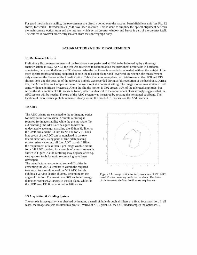
Preliminary flexure measurements of the backbone were performed at NBI, to be followed up by a thorough charcterisation at ESO. At NBI, the test was restricted to rotation about the instrument center axis in horizontal orientation, i.e. a zenith distance of 90 degrees. Also the backbone is essentially unloaded, without the weight of the three spectrographs and being supported at both the telescope flange and lower end. In essence, the measurement only examines the flexure of the Pre-slit Optical Table. Cameras were placed on rigid towers at the UVB and VIS slit positions and the position of the reference pinhole was recorded during a full revolution of the backbone. During this, the Active Flexure Compensation mirrors were kept at a constant setting. The image motion was similar in both arms, with no significant hysteresis. Along the slit, the motion is 0.02 arcsec, 10% of the tolerated amplitude, but across the slit a motion of 0.08 arcsec is found, which is identical to the requirement. This strongly suggests that the AFC system will be needed. Flexure of the A&G system was measured by rotating the horizontal backbone. The location of the reference pinhole remained steady within 0.1 pixel (0.015 arcsec) on the A&G camera.
3.2 ADCs
Figure 13: Image motion for two revolutions of VIS ADC barrel #2 after centering inside the backbone. The dotted circle represents the 5µm / 0.02 arcsec requirement.
3.3 Acquisition & Guiding System
The on-axis image quality was checked by imaging a small pinhole through all filters at a fixed focus position. In all cases, the image analysis resulted in a profile FWHM of ≤ 1.5 pixel, i.e. the CCD undersamples the optics PSF.
The ADC prisms are cemented to the re-imaging optics for maximum transmission. Accurate centering is required for image stability while the prisms rotate. To aid centering, the ADCs are designed to have an undeviated wavelength matching the 405nm Hg line for the UVB arm and the 633nm HeNe line for VIS. Each lens group of the ADC can be translated in the two lateral directions, using pairs of fine pitch pushing screws. After centering, all four ADC barrels fulfilled the requirement of less than 5 µm image wobble radius for a full ADC rotation. An example of a measurement is shown in Figure .As the centering may degrade after e.g. earthquakes, tools for rapid re-centering have been developed. The manufacturer encountered some difficulties in cementing the ADC elements to within the required tolerance. As a result, one of the VIS ADC barrels exhibits a varying degree of coma, depending on the angle of rotation. The worst case 80% encircled energy diameter reaches 0.24 arcsec in the slit plane, while for the UVB arm, EE80 remains below 0.09 arcsec.

The A&G slide and filter wheel motions have been tested at temperatures from -10°C to +20°C with satisfactory results. The use of the A&G slide requires moving to 5 pre-determined positions with good repeatability. A test of the positioning accuracy following an initialisation resulted in an RMS error of 0.4 milliarcsec, some 100mm away from the initialisation point. For arbitrary positioning, a periodic error with an amplitude of 6 milliarcsec is present in the worm drive must be taken into account. The time to move to an adjacent position on the focal plane mirror is less than 10 seconds. Any filter position can be moved into the beam in less than 4 seconds. The observed image offset due to filter wedge was typically 0.1 pixel, or 0.02 arcsec. 3.5 Active Flexure Compensation (AFC)
X-shooter consists of three spectrographs, each with its own slit. The image of the object in the Cassegrain focal plane is relayed to the slit plane via dichroics, re-imaging optics, and (in the case of the UVB and VIS arms) ADCs. All are located in the Backbone, see Fig. 1. During “operational conditions” (ZD 0 – 60 degrees, temperature 0-15 degC, gradients of up to 5 degC/night), the projected position of each of the three slits in the Cassegrain focal plane must be maintained to better than 0.08 arcsec (goal 0.04) from its position at Zenith. This specification was derived from spectrophotometric accuracy requirements. Extensive analysis was done during the Final Design; it was found that the mechanical and thermal stability of the backbone would not be sufficient to guarantee that these requirements will be respected using only a passive structure. X-shooter is therefore equipped with an Active Flexure Compensation (AFC) system that actively maintains co-alignment of the 3 spectrograph slits, regardless of the orientation of the instrument with respect to gravity, or distortions due to thermal gradients. The principle is based on minimizing the amount of shift between lines in arc spectra taken using a 250 µm (0.5 arcsec) pinhole in the 45 degree A&G mirror, and similar spectra taken with a pinhole in each of the 3 slit units. The individual steps in the AFC and acquisition process are:
1. Take an arc spectrum of the spectrograph only (select pinhole in the slit unit, larger aperture in the A&G unit). Only the central 1000 x 1000 window of the CCDs is read in fast readout mode. Including wiping and other overheads, readout takes about 7 sec.
2. Take an arc spectrum, using the pinhole in the A&G slide, the image of which is passed by a larger aperture in slit unit.
3. Analyze the amount of shift between the spectra taken in steps 1 and 2. The shift is measured using autocorrelation of about 10 lines in one or two orders near the center of the wavelength range of each arm. In case shifts are zero, it means that the image of the alignment pinhole coincides with the position of the pinhole in the slits.
4. Correct any shifts by applying offsets to the tip-tilt tables. 5. Repeat steps 2 – 4 (optional). 6. Proceed with object acquisition and object centroiding. The alignment pinhole is visible in the field of the
A&G camera and acts as reference during the centroiding. The effects of differential atmospheric refraction between the off-axis guide probe of the VLT, the selected filter of the A&G unit and the center wavelengths of the spectrographs are taken into account by the software.
Steps 1 – 5 are expected to take between 60 – 90 seconds. It is planned to perform AFC whenever the telescope slews to a new object, and for long observations on the same object at least once per hour. After a slew operation, AFC will run in parallel to telescope Active Optics, which typically lasts 2 minutes, and so it will not add time overheads. The image taken under step 1 is also stored and appended to the science frame(s), since it contains useful information on spectrograph drift and flexure. An example of arc spectra taken with this scheme is given in Fig. 14. Further testing is planned and will address simultaneous execution in all 3 arms using the same lamp, line selection in view of blending, tuning of exposure times to minimize possible remanence effects, especially in the NIR, and elimination of step 5.

Figure 14: Example of a pinhole arc spectrum obtained during the AFC procedure. Boxes show 11 lines used for the cross-correlation. The first tests shows that flexures can be corrected to better than 0.1 pix in two iterations.
4-MEASURED PERFORMANCES
4.1 Predicted Efficiency
Compared to efficiencies predicted at Final Design Review in June 2006, most delivered optical components are well above specifications in terms of efficiency. In particular, critical components such as dichroics and gratings are of extremely good quality. As a result, the predicted total efficiency, obtained by multiplying actual measured efficiencies of individual components, is very high as can be judged from Figure 15. Based on these values, we have computed the expected limiting AB magnitudes at blaze in 1 hour for a S/N of 10 per spectral bin using a first version of the Exposure Time Calculator (ETC), see Figure 16. The model for the ETC uses the as-built values for optics and detector efficiency/noise but still contains some assumptions that need confirmation during
Figure 15: Total efficiency at blaze (atmosphere + telescope + instrument, excluding slit losses) obtained by combining actual measured efficiencies of individual optical components.
Figure 16: Limiting AB magnitude of X-shooter per spectral bin at S/N=10 in a 1 hour exposure. In black: UVB arm. In gray: the VIS arm. Other parameters: air mass 1.2, 0.8” seeing, 1” slit, 2x binning in spectral direction.

commissioning, like the quality of the spectral extraction and sky subtraction, and the values of background in the infrared bands. The decrease in efficiency to the blue of the UVB range is due to the atmospheric absorption, at the red side of the VIS band it is due to the decrease in efficiency of the CCD.
4.2 Spectral and Spatial resolution
Image quality performances of both spectrographs are well within specifications. The spectral resolution measured with a 1.0” slit is ~5000 for the UVB spectrograph and ~8000 for the VIS spectrograph. With a 0.6” slit, UVB and VIS spectrographs reach R~8000 and R~14000 respectively, see Fig. 17. Figure 17: Spectral resolution in UVB (grey) and VIS arms (black). The circles represent the median for spectral resolution as measured on a large number of non-blended Th-Ar lines. The short horizontal lines represent the minimum specification for these slit widths. The curves are predictions for other slit widths, using a simple model tuned to match the measurements with 0.6 and 1 arcsec slit widths. X-Shooter has a number of user-selectable slit widths between 0.5 and 1.5 arcsec, and a 5 arcsec slit for flux calibration.
5-CONCLUSIONS The final AIV and the measured performance of the Backbone and the UVB and VIS spectrographs has proven our basic instrument concept, and shows that this part of the X-shooter instrument is fully compliant with the design specifications, and for the measured efficiencies, even higher than expected. We are now looking forward to the upcoming installation of the instrument at the VLT, and to deliver a well tested instrument with unprecedented efficiency for single target observations to the ESO community by the first half of 2009.
01,0002,0003,0004,0005,0006,0007,0008,0009,000
10,00011,00012,00013,00014,00015,000
0.4 0.6 0.8 1 1.2 1.4 1.6 1.8 2
Slit width (")
Res
olu
tion
4

REFERENCES
[1] P. Spano, B. Delabre, A. N. Sørensen, F. Rigal, A. de Ugarte Postigo, R. Mazzoleni, G. Sacco, P. Conconi, V. De Capprio, N. Michaelsen, The optical design of X-Shooter for the VLT, Proc. SPIE Vol. 6269, 62692X, (2006).
[2] N. Michaelsen, V. De Caprio, N. C. Jessen, J. Lizon, R. Mazzoleni, M. Riva, P, Spano, A. N. Sørensen, M. Tintori, D. W. Wistisen, H. Dekker, P. Kjærgaard Rasmussen, F. M. Zerbi, S. D’Odorico, The X-Shooter spectrograph: a new concept of mechanical assembly for a multiple-arm Cassegrain instrument, Proc. SPIE Vol. 6269, 62692Z, (2006)
[3] S. D’Odorico, H. Dekker, R. Mazzoleni, J. Vernet, I. Guinouard, P. Groot, F. Hammer, P. Kjærgaard Rasmussen, L. Kaper, R. Navarro, R. Pallavicini, C. Peroux, F. M. Zerbi, X-shooter, UV to K band, intermediate resolution, high efficiency spectrograph for the VLT: status report at the Final Design Review, Proc. SPIE Vol. 6269, 626933, (2006).
[4] L. Kaper, S. D’Odorico, F. Hammer, R. Pallavicini, P. K. Rasmussen, H. Dekker, P. Francois, P. Goldoni, I. Guinouard, P. J. Groot, J, Hjorth, M. Horrobin, R. Navaro, F. Royer, P. Santin, J. Vernet, F. Zerbi, X-shooter: a medium-resolution, wide-band spectrograph for the VLT, ESO Workshop “Science with the VLT in the ELT era”, arXiv: 0803.0609v1 (2008).
[5] J. Vernet, H. Dekker, S. D’Odorico, R. Pallavicini, P. Kjærgaard Rasmussen, L. Kaper, F. Hammer, P. Groot and the X-shooter team, Comming soon on stage: X-shooter, The Messenger, 130, 5 (2007).
[6] P. Bristow, F. Kerber, M. R. Rosa, Advanced Calibration techniques for Astronomical Spectrographs, The Messenger, 131, 2 (2008).