X-ray Optics at NASA/MSFC
36
Sandia Apr 2015 X-ray Optics at NASA/MSFC Brian Ramsey X-ray Astronomy Group Astrophysics Office NASA / Marshall Space Flight Center
Transcript of X-ray Optics at NASA/MSFC

X-Ray Astronomy GroupSandia Apr 2015
X-ray Optics at NASA/MSFC
Brian Ramsey
X-ray Astronomy Group
Astrophysics Office
NASA / Marshall Space Flight Center

X-Ray Astronomy GroupSandia Apr 2015
X-Ray Astronomy
Birth of X-Ray Astronomy
• In 1962, Riccardo Giacconi and colleagues at AS&E flew sounding rocket to look at x-ray fluorescence from the moon
• Lunar signal was overshadowed by very strong emission from the Scorpious region
• Discovered the first extra-solar x-ray source, Sco X-1, and pervasive x-ray background
• This was the effective birth of x-ray astronomy

X-Ray Astronomy GroupSandia Apr 2015
X-Ray Astronomy
First X-Ray Satellite
The UHURU spacecraft was launched in 1970
It weighed just 140 pounds, not much more than the rocket experiment
It operated for 3 years and discovered 339 sources in the whole sky

X-Ray Astronomy GroupSandia Apr 2015
Today .. The Chandra Observatory
• School-bus-size x-ray observatory
• 100,000 times more powerful than UHURU
• Uses special mirrors to form highly detailed images
• In deep fields, more than 1000 new sources per square degree

X-Ray Astronomy GroupSandia Apr 2015
X-Ray Optics
Why focus x rays ?1) Imaging - obvious
2) Background reduction
- Signal from cosmic sources very faint, observed against a large background
- Background depends on size of detector and amount of sky viewed
> Concentrate flux from small area of sky on to small detector
enormous increase in sensitivity
First dedicated x-ray astronomy satellite – UHURU mapped 340 sources with large area detector (no optics)
Chandra observatory - ~ same collecting area as UHURU
5 orders of mag more sensitivity --- 1,000 sources / sq degree in deep fields
1 background count / keV year !
X-Ray Optics has revolutionized x-ray astronomy

X-Ray Astronomy GroupSandia Apr 2015
X-ray Optics

X-Ray Astronomy GroupSandia Apr 2015
Approaches (flown so far [Soft X Ray])
Classical Optical Grinding and Polishing
Chandra, Rosat, Einstein
Advantage: Superb angular resolution
Disadvantage: High cost, large mass, difficult to nest
Electroformed Nickel Replication *XMM, JETX/Swift, SAX
Advantage: High nesting factor, good resolution
Disadvantage: Significant mass (high density of nickel)
Segmented foil
ASTRO-E, ASCA, BBXRT
Advantage: Light weight, low cost
Disadvantage: Relatively poor angular resolution (few-arc-minute-level)

X-Ray Astronomy GroupSandia Apr 2015
7. Electroform NiCo
shell onto mandrel
(+)(+) (-)
6. Ultrasonic clean
and passivation
8. Separate optic
from mandrel in
cold water bath
1. CNC machine
mandrel from
aluminum bar
2. Chemical clean
and activation
& electroless nickel
(EN) plate
3. Diamond-turn
to ~ 600Å, sub-
micron figure
accuracy
4.Superpolish
to 3 - 4Å rms
finish
5. Metrology
on mandrel
Shell Fabrication
Mandrel Preparation
Electroformed Nickel Replication

X-Ray Astronomy Group
MSFC Infrastructure

X-Ray Astronomy GroupSandia Apr 2015
Electroform Ni/Co
shell onto mandrel
Mandrel - machining Al bar,
electroless Nickel coating,
diamond turning and
polishing
Metrology on
mandrel
MSFC Developments : Electroformed Nickel Replication
(+)(+) (-)
Separate optic
from mandrel in
cold water bath
Mandrel polishing
X-ray mandrel
Metrology
X-ray shell electroforming
Replicated X-ray shells

X-Ray Astronomy GroupSandia Apr 2015
ENR Development at MSFC
Nickel is a heavy material (9 g / cm3). For light-weight optics, shells must be very thin (~ 0.1 mm [0.004”] at ~0.25-m diameter to meet Con X HXT weight budget) yet strong enough to withstand the stresses of fabrication and subsequent handling without being permanently deformed at the micron level.
Adhesion / Release
• Reduce adhesion of plated shell to mandrel so that shell can release easily
Material Properties
• Develop nickel alloy with much higher strength than pure nickel
Stress Control
• Small amount of stress distorts thin-shell optics
• Fine tune plating bath chemistry and keep electric fields uniform
X-Ray Astronomy GroupSandia Apr 2015
ENR Development
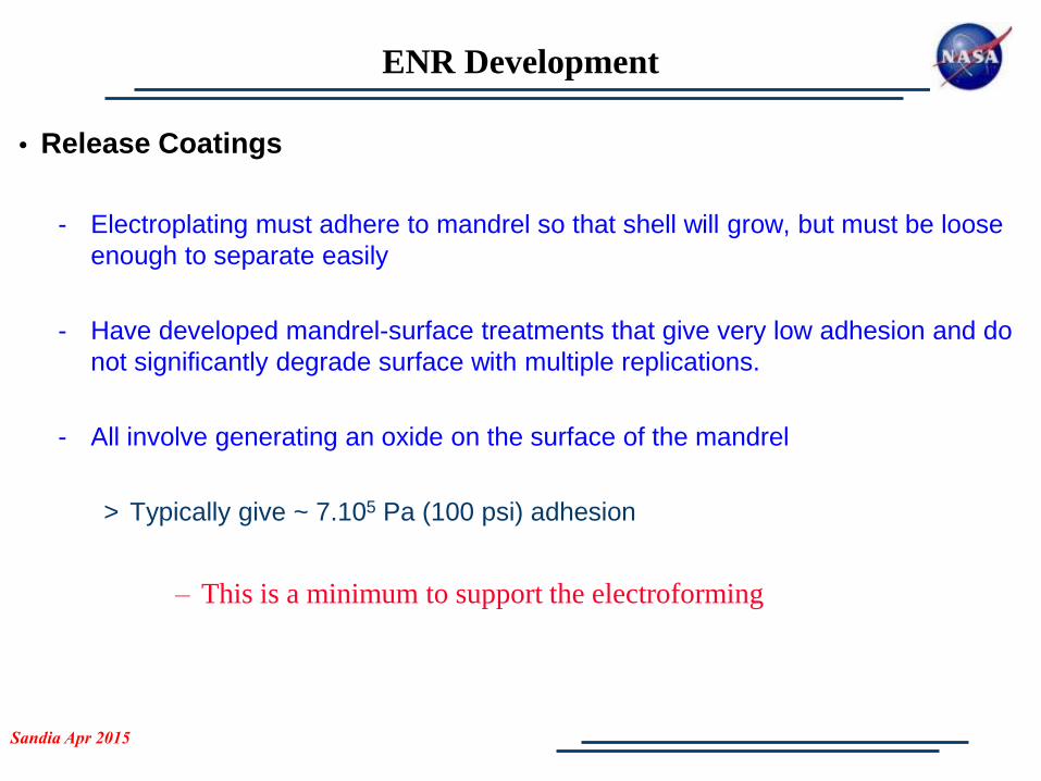
• Release Coatings
- Electroplating must adhere to mandrel so that shell will grow, but must be loose
enough to separate easily
- Have developed mandrel-surface treatments that give very low adhesion and do
not significantly degrade surface with multiple replications.
- All involve generating an oxide on the surface of the mandrel
> Typically give ~ 7.105 Pa (100 psi) adhesion
– This is a minimum to support the electroforming

X-Ray Astronomy GroupSandia Apr 2015
ENR Development
Thin shells can experience large strain stresses under separation
from a mandrel
Stress =(CTE al-CTEni). T.Youngs mod
Example at right, show 0.25-mm-thick shell released from treated
mandrel .. Stress ~ 35 MPa (5 ksi)
A shell 0.12-mm thick would experience twice this stress
Small stresses, well below the yield stress
of a material can cause microyielding, of
importance to high-resolution optics
We have developed alloys with higher
yield strengths than pure nickel
Have made shells from this alloy,
just 0.075-mm-thick (0.003”)
Permanent Strain Versus Applied Stress
0
20
40
60
80
100
120
0.0 10.0 20.0 30.0 40.0 50.0 60.0
Stress (ksi)
Str
ain
(p
pm
)
Nickel Cobalt Alloy Regular Nickel

X-Ray Astronomy GroupSandia Apr 2015
ENR Development
Plating stress control
Need to control the stress to ~ 10’s psi to maintain 10-arcsec-
level figure …adjust chemistry of bath to give flat uniform
stress
Stress still varies with plating current density, so in turn need
to control field … use models of plating bath to fine-tune
layout of shields which modify field
50M1 S12-S13
12.00
12.20
12.40
12.60
12.80
13.00
13.20
13.40
13.60
13.80
14.00
0 5 10 15 20 25
Inches from "P"
Inches/1
000
Thickness 50M1S13 Thickness 50M1S12
"P "H"S13
S12
Resulting deposit is very uniform,
so stress variations are very low
04/08/03 STRESS Bath - 62 3300 Liter; 120 F; 1.5
V Input Agitation; Gauge 191
0.00
0.50
1.00
1.50
2.00
10 11 12 13 14 15 16 17
Current Density ASF
Str
ess k
si

X-Ray Astronomy GroupSandia Apr 2015
ENR Development

X-Ray Astronomy GroupSandia Apr 2015
Replicated X-ray optic projects at MSFC
Non-astronomical applications
Astronomical applicationsFOXSIART-XC
ART-XC eROSITA
Navigator
Neutron imaging
HEROES
Medical imaging
MicroX

X-Ray Astronomy GroupSandia Apr 2015
Description:
ART-XC is a medium energy x-ray telescope that will fly aboard the Russian Spectrum-Rontgen-Gamma Mission.
ART-XC will fly in 2016 and during its 7-year mission will conduct a 4-year survey of the sky, with an additional 3 years for follow-on studies
MSFC will provide x-ray optics modules for the ART-XC instrument.
Delivery of the optics is scheduled for late Summer 2014
ART-XC
Customer:
Space Research Institute of the Russian Academy of Sciences (IKI)
Funded under an International Reimbursable Agreement between NASA and IKI

X-Ray Astronomy GroupSandia Apr 2015
ART-XC Optics Configuration
Parameter Value
Number of Mirror Modules 7=4+3 (plus 1 spare)
Number of Shells per Module 28
Shell Coating > 10 nm of iridium (> 90% bulk density)
Shell Total Length, inner and outer diameters
580 mm, 50 mm, 150 mm
Encircled Half Energy Width 25 arcsec HPD on axis (measured)
Mirror Module Effective Area ≥ 65 cm2 at 8 keV (on axis)
Module Focal Length 2700±1 mm
MSFC has designed and is fabricating
four ART x-ray optics modules under an International Reimbursable Agreement between
NASA and with IKI (delivery – August 2014)
three + one spare ART modules under Agreement regarding Cooperation on the ART-XC
Instrument onboard the SRG Mission between NASA and IKI (delivery – October 2014)

X-Ray Astronomy GroupDoE Workshop in X-Ray Optics
Description:
FOXSI is a sounding rocket based payload consisting of x-ray optics (provided by MSFC) and focal plane detectors provided by ISAS/Japan.
FOXSI has 7 mirror modules each with 7 (10 Foxsi-2) nested shells. Measured FWHM = 6-7 arcsec (with 5 arcsec detector).
FOXSI designed to make hard-x-ray observations (5-15 keV) of solar nanoflares, thought to play an important role in heating the corona to millions of degrees.
FOXSI was launched from White Sands missile range on 2 Nov, 2012, for a ~ 6 min flight.
FOXSI-2 version had successful flight from White Sands on 11 Dec, 2014
Customer:
University of California, Berkeley
P.I. Sam Krucker
Funded by the Science Mission Directorate, through the low-cost access to space program.
Focusing Optics X-ray Solar Imager (FOXSI)

X-Ray Astronomy GroupSandia Apr 2015
FOXSI
Mirror shell alignment and installation station
Module net angular resolution after
detector resolution removed

X-Ray Astronomy GroupSandia Apr 2015
Description:
Micro-X is a sounding rocket based payload consisting of x-ray optics (provided by MSFC) and a calorimeter detector led by MIT
Micro-X will fly in early 2017 and make high-spectral-resolution images of supernova remnants Puppis A and Cas A.
The 0.5m diameter optics are under construction at MSFC. Completion schedule for 2016.
Micro-X
Customer:
Massachusetts Institute of Technology / Tali Figueroa
Funded by the Science Mission Directorate, through the low-cost access to space program.
Micro-X mandrel on diamond turning machine

X-Ray Astronomy GroupSandia Apr 2015
High Energy Replicated Optics to Explore The Sun
HEROES mission, a collaboration with GSFC, was part of the Hands On Project Experience (HOPE), with the primary goal of training NASA scientists and engineers to fly a hard x-ray (20-75 keV) telescope on a balloon platform.
Launch (9/21/2013) Flight
Heliophysics- Investigate electron acceleration in the
non-flaring solar corona by searching for the hard X-ray signature of energetic electrons.
- Investigate the acceleration and transport of energetic electrons in solar flares.
Crab Nebula 2-10 keV
Chandra
Astrophysics Investigate the scale of high energy
processes in a pulsar wind nebula.
Investigate the hard X-ray properties of astrophysical targets such as X-ray binaries and active galactic nuclei.
22

X-Ray Astronomy GroupSandia Apr 2015
HEROES Optics
Mirror shells per module 14 (6 mod), 13 (2 mod)
Inner, outer shell diameters 50, 94 mm
Total shell length 610 mm
Focal length 6 m
CoatingSputtered iridium,
~ 20 nm thick
Number of mirror modules 8
Effective area~ 85 cm2 at 40 keV,
~ 40 cm2 at 60 keV
Angular resolution (module) ~25 arcsec FWHM
Field of View9 arcmin at 40 keV
5 arcmin at 60 keV
23

X-Ray Astronomy GroupSandia Apr 2015
Spinoff Application: Neutron Microscopy

X-Ray Astronomy GroupSandia Apr 2015
Applications:
Fuel cell development (resolving
concentration gradients in electrodes
requires the highest possible spatial
resolution )
Lithium-air batteries development
(lithium-air batteries have 10x
storage capacity of commercial
lithium-ion batteries )
Non-destructive evaluation of
nuclear fuel rods life cycle
Also: –Understand targeted drug delivery
–Advance oil and gas recovery
–Improve the safety of nuclear fuel cladding by imaging the grain structure
of ZrH
–Develop additive manufacturing of metal alloys
–Reveal solar cell morphologies to reduce the cost of large area solar
arrays
–Enhance efficiency of room temp. magnetic refrigeration by imaging 3D
magnetic structures
–Solve protein structures in solution, 2/3 of all proteins can’t be
crystallized
–Understand polymer and block copolymer self-assembly and hydrogels
–Distinguish internal structure and morphology of graded nanoparticles
–Understand magnetic nanoparticles for hyperthermic cancer treatment,
MRI contrast agents
-And more …
Optics for new cold neutron imaging instrument at NIST
Source for funding – NIST director’s fund
• Task 1 (Demonstration of high resolution
neutron optics)
• Task 2 (Neutron optics with magnification 1)
• Task 3 (Neutron optics with large
magnification)
Status – Negotiations on an Interagency
Agreement for Task 1
Future home for our
opticsNIST Beamline Hall
Left:The FOXSI optic, with
7 nested mirrors
Right: 2 parabolic sections
from one FOXSI shell
were used to create a
1:1 prototype neutron
microscope
Neutron microscope prototype

X-Ray Astronomy GroupSandia Apr 2015
Development a grazing incidence optics for medical applications – radionuclide imaging in
small animals to perform functional analysis
Collaborators
Lawrence Livermore National LaboratoriesHarvard-Smithsonian Center for Astrophysics
University of California @ San Franciso
Funded by – National Institute of Health
Radionuclide imaging X-ray optics
Optics
Novel use of reflective optics
Can provide 100 µm spatial resolution which is 10 fold better resolution compared to existing techniques in the
field
~60 mm in length and ~30 mm in diameter; much smaller in size compared to the astronomical optics regularly
fabricated at MSFC
Nested shells - Confocal hyperbola and ellipse geometry
Geometry details
Total length = 3 m
Object distance (u) = 0.6 m
Image distance (v) = 2.4 m
Magnification = 4
Reflection angle = 0.5 deg
Image
Optics
u v
Object
26

X-Ray Astronomy GroupSandia Apr 2015
New Developments: Differential Deposition
• What
• Differential deposition is a technique for correcting figure errors in optics
• How
• Use physical vapor deposition to selectively deposit material on the mirror
surface to smooth out figure imperfections
• Why
• Can be used on any type of optic, full-shell or segmented, mounted or
unmounted
• Can be used to correct a wide range of spatial errors. Could be used in
conjunction with other techniques… e.g. active optics.
• Technique has been used by various groups working on synchrotron optics
to achieve sub-μradian-level slope errors
27

X-Ray Astronomy GroupSandia Apr 2015
Coating Configuration
28

X-Ray Astronomy GroupSandia Apr 2015
Surface profile metrology
Develop correction profile “Hitmap”
Simulations – translation velocity of shell
Differential deposition
Surface profile metrology
X-ray testing
Process Sequence - Differential Deposition
29

X-Ray Astronomy GroupSandia Apr 2015
Process Sequence – Differential Deposition
Simulated correction sequence showing parabolic axial figure profile before (top left) and
after 3 stages of correction using a beam of FWHM = 14mm, 5.2 mm and 1.7 mm
respectively. The dotted line gives the desired figure and the solid line gives the figure
obtained at each stage. Overall, resolution improved from 7.8 arcsec to 0.9 arcsec HEW (2
bounce equivalent).
30

X-Ray Astronomy GroupSandia Apr 2015
• Variation of sputtered beam profile along the length of mirror – particularly for short
focal length mirrors – Model and correct
• Deviation in the simulated sputtered beam profile from actual profile, beam non-
uniformities, etc. – Quantify and correct
• Positional inaccuracy of the slit with respect to mirror – Model effects to derive
requirements
• Metrology uncertainty – Upgrade metrology system
• Stress effects – Quantify and control stress
Possible Practical Limitations We Are Addressing
31

X-Ray Astronomy GroupSandia Apr 2015
Coating Systems (DC magnetron)
Vertical chamber for
segmented optics Horizontal chamber for 0.25-m-
scale full shell optics
32

X-Ray Astronomy GroupSandia Apr 2015
Coating Systems
X-ray mirror held in a rotating and
translating collet
Sputtering target
Mask
X-ray mirror
Horizontal differential-deposition chamber
Sputtering head with copper mask
positioned inside shell
33

X-Ray Astronomy GroupSandia Apr 2015
Test # 1: 150 mm diameter shell P-end, 2 stages of correction
0
50
100
150
200
250
300
350
400
360.57
116.00
64.36
Ang
str
om
s
RMS value of higher-order frequencies
pre-correction
post1-correction
post2-correction
0 20 40 60 80 100 120 140 160 180-2000
-1500
-1000
-500
0
500
1000
1500
mm
Ang
str
om
s
Profile pre- & post- correction
pre-correction
post1-correction
post2-correction
complete profile only higher-order frequencies0
1
2
3
4
5
6
7
8Calculated HPD
7.08
3.68
2.87
6.71
2.95
1.86
arc
-seco
nds
pre-correction
post1-correction
post2-correction
0 20 40 60 80 100 120 140 160 180-800
-600
-400
-200
0
200
400
600
800
mm
Ang
str
om
s
Higher-frequencies of profile
pre-correction
post1-correction
post2-correction
2 bounce equivalent
ƛ < 4 cm
ƛ < 4 cm

X-Ray Astronomy GroupSandia Apr 2015
0 20 40 60 80 100 120 140 160 180-5000
-4000
-3000
-2000
-1000
0
1000
2000
3000
mm
Ang
stro
ms
Profile pre- & post- correction
pre-correction
post1-correction
post2-correction
Test # 2: 150 mm diameter shell - 2 stages of correction
0 20 40 60 80 100 120 140 160 180-800
-600
-400
-200
0
200
400
600
800
mm
Ang
stro
ms
Higher-frequencies of profile
pre-correction
post1-correction
post2-correction
complete profile only higher-order frequencies0
2
4
6
8
10
12
10.40
6.356.90 6.91
3.17
1.71
arc
-sec
on
ds
Calculated HPD
pre-correction
post1-correction
post2-correction
0
50
100
150
200
250
300
350327.20
107.76
62.46
Ang
str
om
s
RMS value of higher-order frequencies
pre-correction
post1-correction
post2-correction
2 bounce equivalent
ƛ < 4 cm
ƛ < 4 cm
ƛ < 4 cm
X-Ray Astronomy GroupSandia Apr 2015
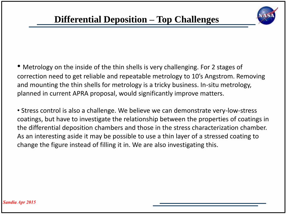
Differential Deposition – Top Challenges
• Metrology on the inside of the thin shells is very challenging. For 2 stages of
correction need to get reliable and repeatable metrology to 10’s Angstrom. Removing and mounting the thin shells for metrology is a tricky business. In-situ metrology, planned in current APRA proposal, would significantly improve matters.
• Stress control is also a challenge. We believe we can demonstrate very-low-stress coatings, but have to investigate the relationship between the properties of coatings in the differential deposition chambers and those in the stress characterization chamber. As an interesting aside it may be possible to use a thin layer of a stressed coating to change the figure instead of filling it in. We are also investigating this.