X-ray NAVigation for Autonomous XNAV Position Determination
30
XNAV XNAV X-ray NA V igation for Autonomous Position Determination March 29, 2011 National Academies Panel on Robotics, Communication and Navigation Dr. Darryll J. Pines Farvardin Professor and Dean A. James Clark School of Engineering, University of Maryland pines@umd.edu
Transcript of X-ray NAVigation for Autonomous XNAV Position Determination
XNAVXNAVX-ray NAVigation for Autonomous Position Determination
March 29, 2011National Academies
Panel on Robotics, Communication and Navigation
Dr. Darryll J. PinesyFarvardin Professor and Dean
A. James Clark School of Engineering, University of [email protected]

OutlineOutline
•Motivation•What is a Pulsar•History of X-ray NavigationHistory of X ray Navigation•Evolution of a DARPA ProgramXNAV DARPA P•XNAV DARPA Program
•Navigation Results from Tracking Pulsars•Summary/Future thoughts
MotivationMotivation
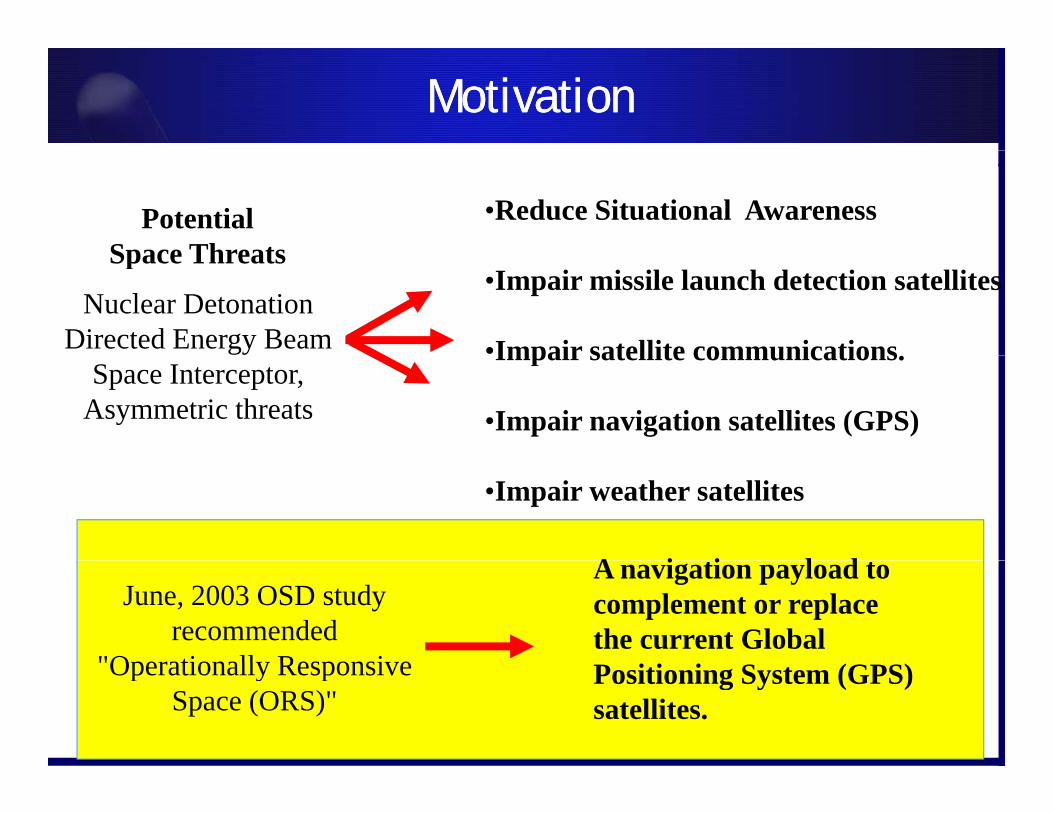
•Reduce Situational AwarenessPotentialSpace Threats
Nuclear DetonationDirected Energy Beam
•Impair missile launch detection satellites
•Impair satellite communications
Space Threats
Space Interceptor, Asymmetric threats
Impair satellite communications.
•Impair navigation satellites (GPS)
•Impair weather satellites
A i ti l d tJune, 2003 OSD study
recommended "Operationally Responsive
A navigation payload to complement or replace the current Global
"Operationally Responsive Space (ORS)"
Positioning System (GPS) satellites.
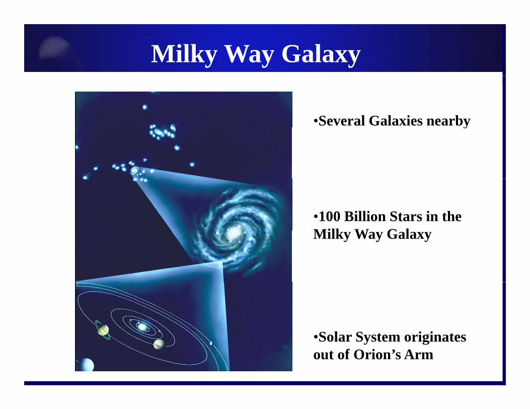
Milky Way Galaxy200 Billion Stars
•Several Galaxies nearbyy
•100 Billion Stars in the Milk W G lMilky Way Galaxy
S l S t i i t•Solar System originates out of Orion’s Arm

X-ray Pulsars As Navigation BeaconsX-ray Pulsars As Navigation Beacons
XX--ray Pulsarsray Pulsars• Intense magnetic fields
accelerate charged Rotation Axis
Radio Beam
X-ray and Gamma-rayPhotons
gparticles
• X-rays are emitted and can be seen periodically
Magnetic Pole
Magnetic Pole
Radio Beam
Magnetic Field
Neutron Star
Radio Beamp yas beams sweep past observers line-of-sight
• Extremely stable -X-ray and Gamma-rayPhotons
Radio Beam
yNature’s Galactic “Lighthouses”
Navigation AccuracyNavigation Accuracy• Governed by pulsar
position location accuracy and timing of arrival of photons
crnttt obsb
ˆ
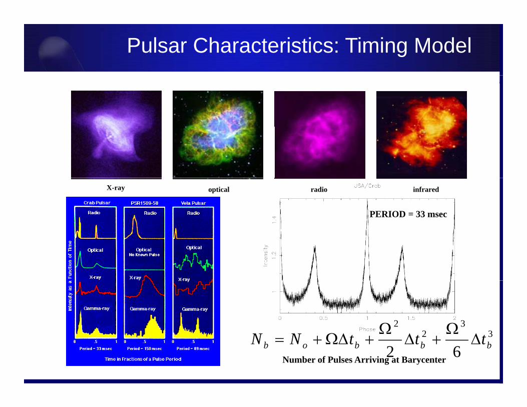
Pulsar Characteristics: Timing Model
PERIOD = 33 msec
X-ray optical radio infrared
33
22 32
62 bbbob tttNN
Number of Pulses Arriving at Barycenter

X-ray Sky X-ray Sky
Catalogued by various telescope missionsCatalogued by various telescope missions• ROSAT mission catalogued 105,924 X-ray objects
– ATNF has detected over 1400 radio pulsars• Working catalogue contains 737 objects
– 79 Rotation powered pulsars
Crab Nebula
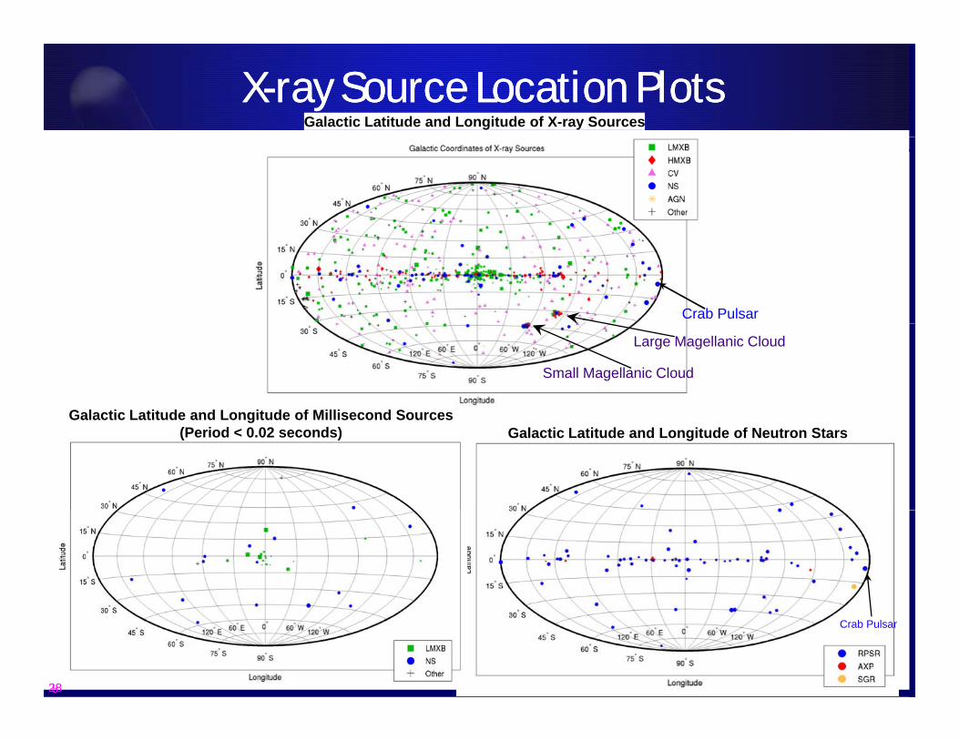
X-ray Source Location PlotsX-ray Source Location PlotsGalactic Latitude and Longitude of X-ray Sources
Crab Pulsar
Galactic Latitude and Longitude of Millisecond Sources
Large Magellanic Cloud
Small Magellanic Cloud
Galactic Latitude and Longitude of Neutron StarsGalactic Latitude and Longitude of Millisecond Sources
(Period < 0.02 seconds)
8
Crab Pulsar
28
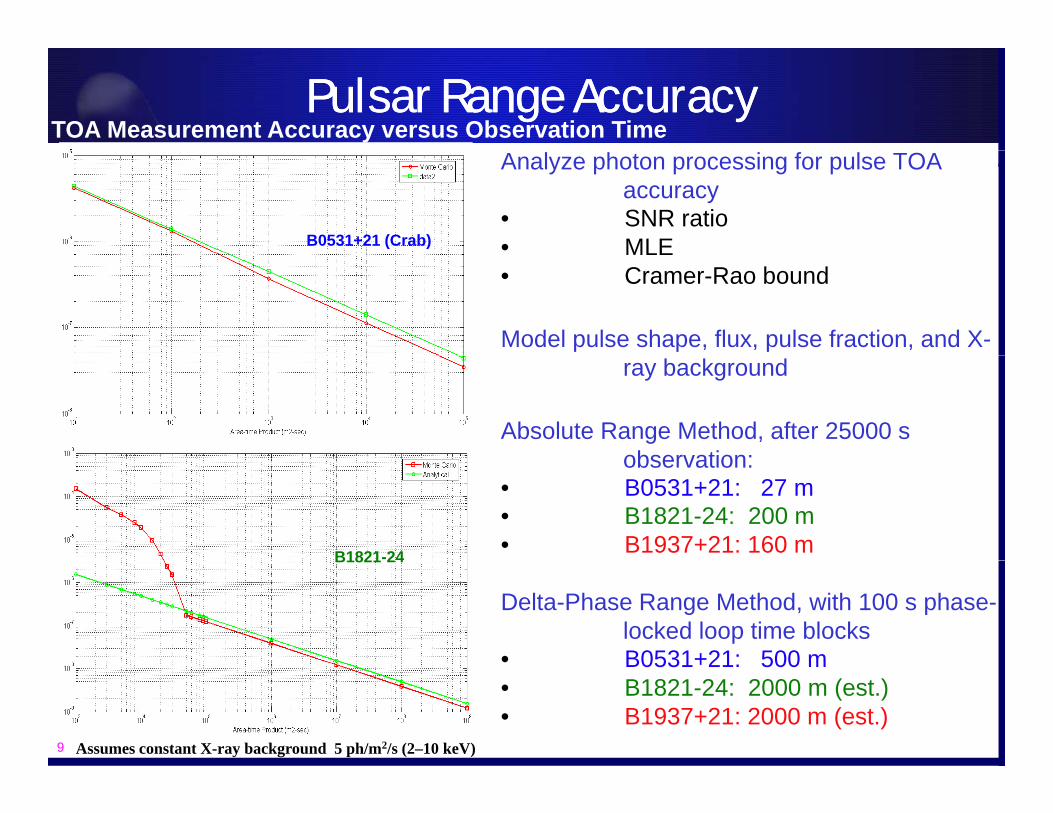
Pulsar Range AccuracyPulsar Range AccuracyTOA Measurement Accuracy versus Observation Time
Analyze photon processing for pulse TOA accuracy
• SNR ratio• MLEB0531+21 (Crab) MLE• Cramer-Rao bound
Model pulse shape, flux, pulse fraction, and X-ray background
Absolute Range Method, after 25000 s observation:observation:
• B0531+21: 27 m• B1821-24: 200 m• B1937+21: 160 mB1821-24
Delta-Phase Range Method, with 100 s phase-locked loop time blocks
• B0531+21: 500 m
B1821 24
9
B0531+21: 500 m• B1821-24: 2000 m (est.)• B1937+21: 2000 m (est.)
Assumes constant X-ray background 5 ph/m2/s (2–10 keV)
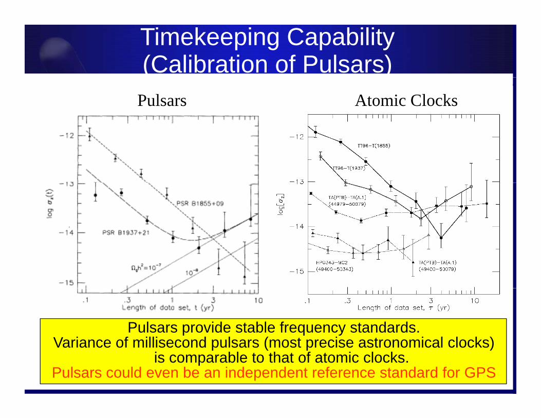
Timekeeping Capability(Calibration of Pulsars)( )
Pulsars Atomic Clocks
Pulsars provide stable frequency standards.Variance of millisecond pulsars (most precise astronomical clocks)Variance of millisecond pulsars (most precise astronomical clocks)
is comparable to that of atomic clocks.Pulsars could even be an independent reference standard for GPS

Timekeeping Ability of Different ClocksTimekeeping Ability of Different Clocks
What is the fundamentalfundamental timekeeping limit?
Allan, 97

History of X-ray NavigationHistory of X-ray Navigation
1930’s Various Theoretical predictions of neutron stars.1967 A. Hewish & J. Bell Discovery of radio pulsars1971 Reichley, Downs & Morris Described using radio pulsars as clocks
Historical Contributions to X-ray Navigation
y, g p1974 Downs Radio Pulsars for Interplanetary Navigation1980 Downs and Reichley Techniques for measuring arrival times of pulsars1981 Chester and Butman Described spacecraft navigation using X-ray pulsars1988 Wallace Planned use of radio stars for all weather navigation1993 Wood Proposed vehicle attitude and navigation using X ray pulsars1993 Wood Proposed vehicle attitude and navigation using X-ray pulsars 1996 Hanson Doctoral thesis on X-ray attitude determination1999 USA Exp. Earth orbit vehicle attitude determination using X-ray sources2005 Sheikh et. Al Navigation using X-ray sources

Evolution of a ProgramEvolution of a Program
2000: Sheikh takes ENAE 741 class and does a project on Pulsar Navigation
X-ray Source Navigation for Autonomous Position Determination Program
2000: Sheikh takes ENAE 741 class and does a project on Pulsar Navigation2001: Sheikh starts working on project under Dr. Pines2002: UMD meets with NRL to discuss X-ray navigation and processing data sets from 1999 USA experiment.2003 Sh ikh ti f i l d t f USA d t tt d i ti2003: Sheikh processes time of arrival data from USA and gets pretty good navigation results. 2003: Pines interviews at DARPA and starts in October.2004: Program approved by DARPA Director in February.2004: Workshop on X-ray Sensors is held in May2004: BAA released in August2004: Sheikh wins GNC best paper award2004: Proposals due in Novemberp2005: Contracts awarded to two teams in May2005: NASA and other agencies get interested in XNAV2006: Phase I near completion2007: Phase II hardware build to be initiated with possible transfer to NASA management2007: Phase II hardware build to be initiated with possible transfer to NASA management2007: Phase II not funded2008-11: Elements of program still funded by NASA and DARPA (XTIM, XNAV elements)

XNAV Program VisionXNAV Program VisionProvide a GPS-free, spacecraft autonomous navigation capability
with a position accuracy < 30 m SEPProvide this capability anywhere in the solar systemProvide this capability anywhere in the solar system
• Develop a revolutionary navigation capability exploiting celestial X-ray sources such as periodic X- Rotation Axis
X-ray and Gamma-rayPhotons
ray pulsars for time, position and attitude determination. Develop high fidelity catalog of candidate
sources
Magnetic Pole
Magnetic Pole
Radio Beam
Magnetic Field
Neutron StarRadio Beam
sources. Develop new X-ray sensors to meet stringent
imaging and timing requirements. Develop advanced navigation algorithms
i i i f i
X-ray and Gamma-rayPhotons
incorporating X-ray photon time of arrival data.
• System capable of operating in various orbit scenarios:sce os: LEO, HEO, GEO, Cislunar, Interplanetary
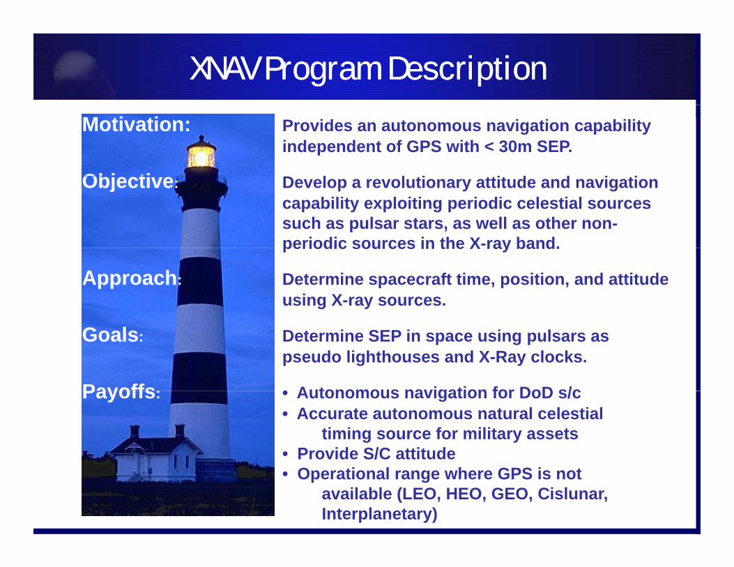
XNAV Program DescriptionXNAV Program Description
Motivation: Provides an autonomous navigation capability independent of GPS with < 30m SEP.
Obj ti D l l ti ttit d d i tiObjective: Develop a revolutionary attitude and navigation capability exploiting periodic celestial sources such as pulsar stars, as well as other non-periodic sources in the X-ray band.periodic sources in the X ray band.
Approach: Determine spacecraft time, position, and attitude using X-ray sources.
Goals: Determine SEP in space using pulsars as pseudo lighthouses and X-Ray clocks.
Payoffs: • Autonomous navigation for DoD s/cPayoffs: • Autonomous navigation for DoD s/c• Accurate autonomous natural celestial
timing source for military assets• Provide S/C attitude • Operational range where GPS is not
available (LEO, HEO, GEO, Cislunar, Interplanetary)

Elements of Operational SystemElements of Operational System
Pulsar DetectionNotional X-Ray Detector System
Notional Satellite
PulsarTiming Models
PulsarCatalogue
Navigation Algorithms
vc
rnrc
GMrnr
Dccrnt sun
b 2322 1ˆln
2ˆ2
1ˆ
Crab NebulaLocation and Properties
X-ray Imager and Photon Counter
TECHNICAL ISSUES TO BE ADDRESSED
• Determination of Source locations
Development of Pulsar Timing Models• Pulsars can be viewed in optical, radio,
i f d X d
PULSAR SOURCES
• Development of Pulsar Timing Models
• Detector design and performance
• Development of Navigation Algorithms
infrared, X-ray, and gamma-ray wavelengths
• X-ray pulsars are bright in the X-ray band
• Evaluation of System Performance
• Evaluation of Terrestial, LEO, GEO, HEO, Interplanetary Applications
band
• X-ray pulsars can only be viewed outside the earth’s atmosphere
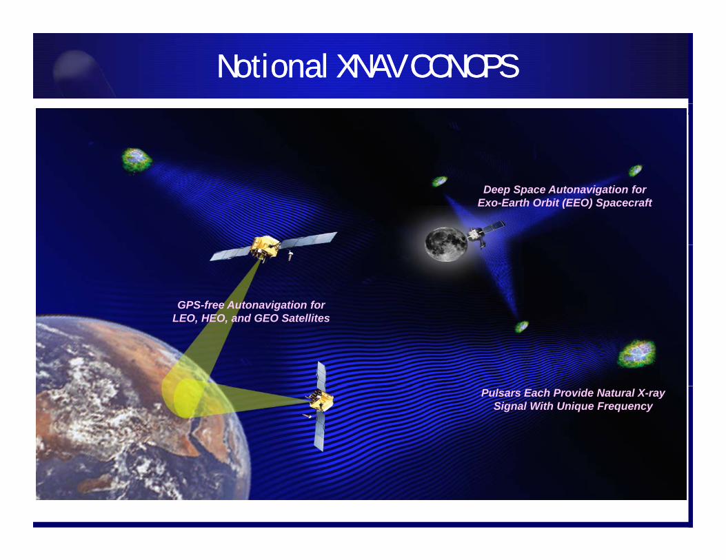
Notional XNAV CONOPSNotional XNAV CONOPS
Deep Space Autonavigation for Exo-Earth Orbit (EEO) Spacecraft
GPS-free Autonavigation for LEO HEO d GEO S t llitLEO, HEO, and GEO Satellites
Pulsars Each Provide Natural X-ray Signal With Unique Frequency

XNAV AnimationXNAV Animation

XNAV Performers/Gov. Teams at a GlanceXNAV Performers/Gov. Teams at a Glance
XNAV Phase 1 performer teams:XNAV Phase 1 performer teams:• Team 1: Naval Research Lab (prime)
Subcontractors:Brookhaven National Lab– Brookhaven National Lab
– MIT/LL– MIT
• Team 2: Ball Aerospace (prime)Associate contractorsAssociate contractors:– National Institute of Standards and Technology– Los Alamos National Lab– Johns Hopkins University Applied Physics Lab
UCBerkeley Univ of Leicester via subcontract to LANL– UCBerkeley, Univ. of Leicester via subcontract to LANL
• NASA Goddard Space Flight Center (GSFC) X-ray Test Facility
Position Updates From Delta-RangePosition Updates From Delta-Range
– Accumulate photons over short time blocks– Compute phase and delta-phase over time
NASA
Bl d d i d– Continually correct position estimate
ObservationEnd
Blend dynamics andmeasurements in
Kalman Filter
Continually correct position estimate– Correct only along line of sight to pulsar
IndividualMeasurement
End
Blocks
NASA
Actual Path
Estimated Path
ObservationStart
NASA/CXC/ASU/J.Hester et al.
Position Updates
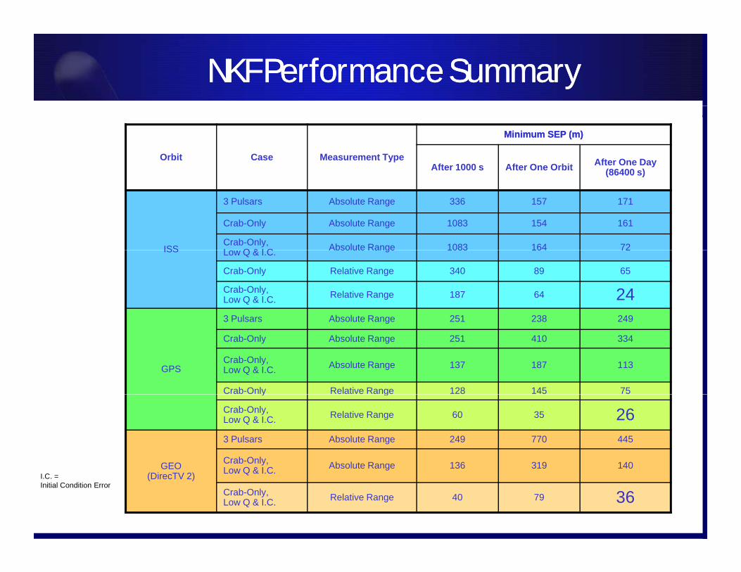
NKF Performance SummaryNKF Performance Summary
Orbit Case Measurement Type
Minimum SEP (m)Minimum SEP (m)
After 1000 s After One Orbit After One Day (86400 s)
ISS
3 Pulsars Absolute Range 336 157 171
Crab-Only Absolute Range 1083 154 161
Crab-Only,L Q & I C Absolute Range 1083 164 72ISS Low Q & I.C. Absolute Range 1083 164 72
Crab-Only Relative Range 340 89 65
Crab-Only,Low Q & I.C. Relative Range 187 64 243 Pulsars Absolute Range 251 238 249
GPS
g
Crab-Only Absolute Range 251 410 334
Crab-Only,Low Q & I.C. Absolute Range 137 187 113
Crab-Only Relative Range 128 145 75y g
Crab-Only,Low Q & I.C. Relative Range 60 35 26
GEO
3 Pulsars Absolute Range 249 770 445
Crab-Only, Absolute Range 136 319 140GEO(DirecTV 2) Low Q & I.C. Absolute Range 136 319 140
Crab-Only,Low Q & I.C. Relative Range 40 79 36
I.C. = Initial Condition Error
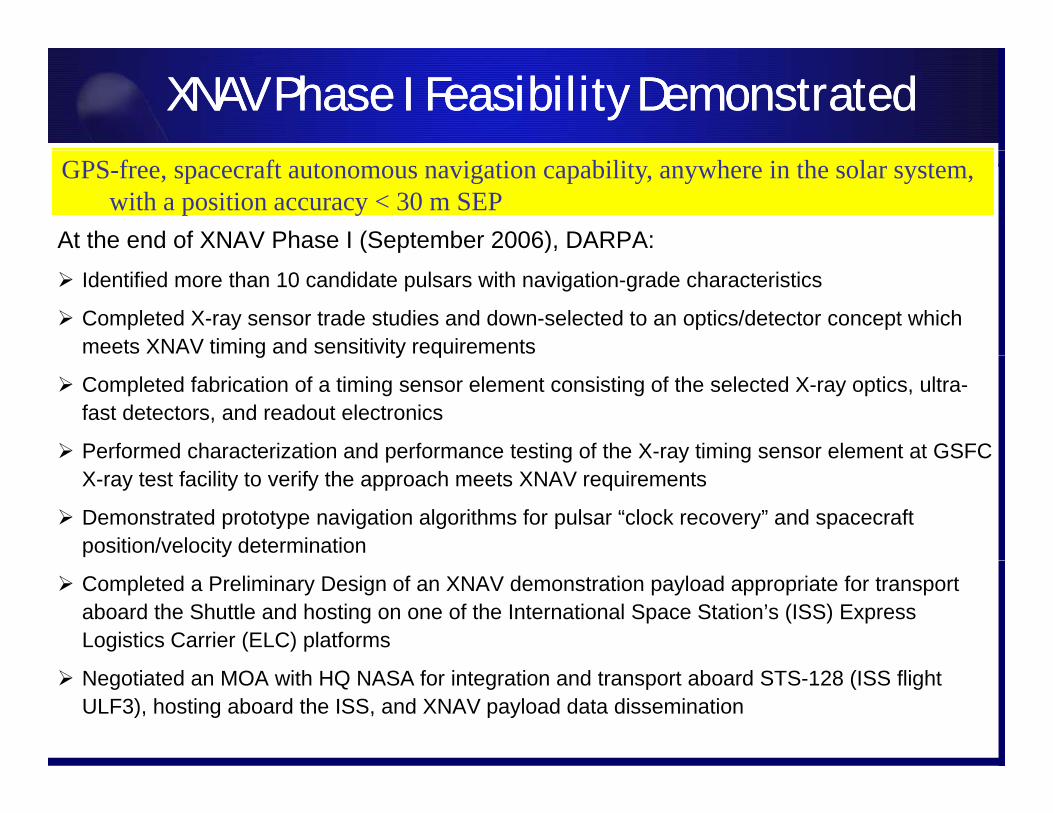
XNAV Phase I Feasibility DemonstratedXNAV Phase I Feasibility Demonstrated
At the end of XNAV Phase I (September 2006), DARPA:
GPS-free, spacecraft autonomous navigation capability, anywhere in the solar system, with a position accuracy < 30 m SEP
( ) Identified more than 10 candidate pulsars with navigation-grade characteristics
Completed X-ray sensor trade studies and down-selected to an optics/detector concept which meets XNAV timing and sensitivity requirementsg y q
Completed fabrication of a timing sensor element consisting of the selected X-ray optics, ultra-fast detectors, and readout electronics
Performed characterization and performance testing of the X-ray timing sensor element at GSFC Performed characterization and performance testing of the X ray timing sensor element at GSFC X-ray test facility to verify the approach meets XNAV requirements
Demonstrated prototype navigation algorithms for pulsar “clock recovery” and spacecraft position/velocity determination
Completed a Preliminary Design of an XNAV demonstration payload appropriate for transport aboard the Shuttle and hosting on one of the International Space Station’s (ISS) Express Logistics Carrier (ELC) platforms
Negotiated an MOA with HQ NASA for integration and transport aboard STS-128 (ISS flight ULF3), hosting aboard the ISS, and XNAV payload data dissemination

For Official Use Only
XNAV Program ScheduleXNAV Program Schedule
PHASE IConcept Feasibility
BAA PADSigned
OnContract
CoDR Nominal Launch
PSRPDR Mid-Term Review
TRRCDR
Concept FeasibilityCharacterize Pulsars
Attitude/position AlgorithmPrototype Detector Design
Prototype Sensor DesignCONOPS Development CoDR
PDR
PHASE IIDevelopment
Pulsar Characterization / NavDesign Development
CDRG0/No-Go
P-IIGo/No-Go
Pre-Ship ReviewDesign DevelopmentFabrication / Assembly / Test
NASA–ISS Mission SupportMission Ops Development
Payload Processing
G0/No-Go
PHASE IIIMission Operations
Initial DeploymentData Collection and Analysis
Data Collection& Analysis
NASA / AF Tech Support
$M Phase I Phase II Phase III
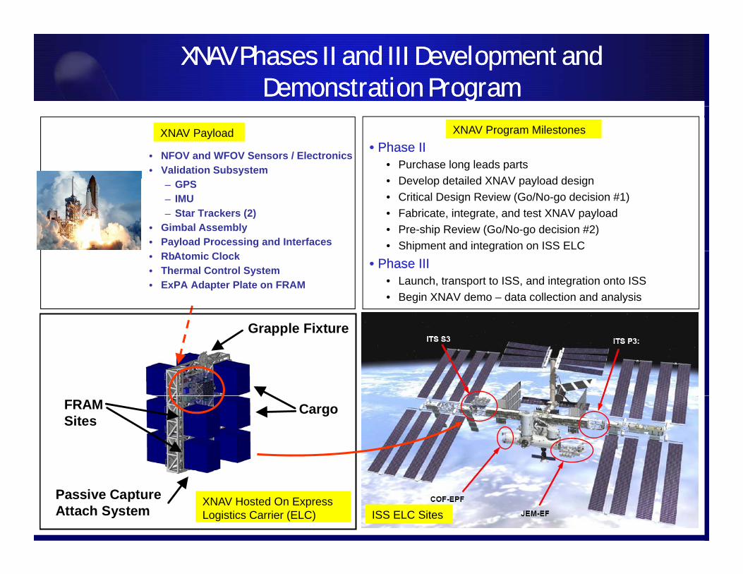
XNAV Phases II and III Development and Demonstration Program
XNAV Phases II and III Development and Demonstration Program
•• Phase IIPhase II• Purchase long leads parts
De elop detailed XNAV pa load design
XNAV Payload XNAV Program Milestones
• NFOV and WFOV Sensors / Electronics• Validation Subsystem
• Develop detailed XNAV payload design• Critical Design Review (Go/No-go decision #1)• Fabricate, integrate, and test XNAV payload• Pre-ship Review (Go/No-go decision #2)• Shipment and integration on ISS ELC
– GPS– IMU– Star Trackers (2)
• Gimbal Assembly • Payload Processing and Interfaces
G l Fi t
p g•• Phase IIIPhase III
• Launch, transport to ISS, and integration onto ISS• Begin XNAV demo – data collection and analysis
• RbAtomic Clock• Thermal Control System• ExPA Adapter Plate on FRAM
Grapple Fixture
CargoFRAMSites
Passive CaptureAttach System
XNAV Hosted On Express Logistics Carrier (ELC) ISS ELC Sites
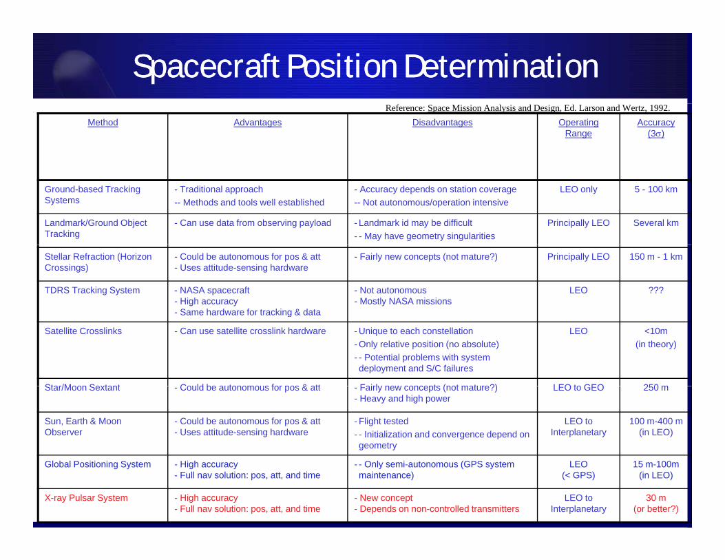
Spacecraft Position Determination Spacecraft Position Determination
Method Advantages Disadvantages Operating Range
Accuracy(3)
Reference: Space Mission Analysis and Design, Ed. Larson and Wertz, 1992.
Ground-based Tracking Systems
- Traditional approach-- Methods and tools well established
- Accuracy depends on station coverage-- Not autonomous/operation intensive
LEO only 5 - 100 km
Landmark/Ground Object Tracking
- Can use data from observing payload - Landmark id may be difficult- - May have geometry singularities
Principally LEO Several km
Stellar Refraction (Horizon Crossings)
- Could be autonomous for pos & att - Uses attitude-sensing hardware
- Fairly new concepts (not mature?) Principally LEO 150 m - 1 km
TDRS Tracking System - NASA spacecraft- High accuracy- Same hardware for tracking & data
- Not autonomous- Mostly NASA missions
LEO ???
g
Satellite Crosslinks - Can use satellite crosslink hardware - Unique to each constellation- Only relative position (no absolute)- - Potential problems with system deployment and S/C failures
LEO <10m(in theory)
Star/Moon Sextant Could be autonomous for pos & att Fairly new concepts (not mature?) LEO to GEO 250 mStar/Moon Sextant - Could be autonomous for pos & att - Fairly new concepts (not mature?)- Heavy and high power
LEO to GEO 250 m
Sun, Earth & Moon Observer
- Could be autonomous for pos & att- Uses attitude-sensing hardware
- Flight tested- - Initialization and convergence depend on geometry
LEO to Interplanetary
100 m-400 m(in LEO)
Global Positioning System - High accuracy- Full nav solution: pos, att, and time
- - Only semi-autonomous (GPS system maintenance)
LEO(< GPS)
15 m-100m(in LEO)
X-ray Pulsar System - High accuracy- Full nav solution: pos, att, and time
- New concept- Depends on non-controlled transmitters
LEO to Interplanetary
30 m(or better?)
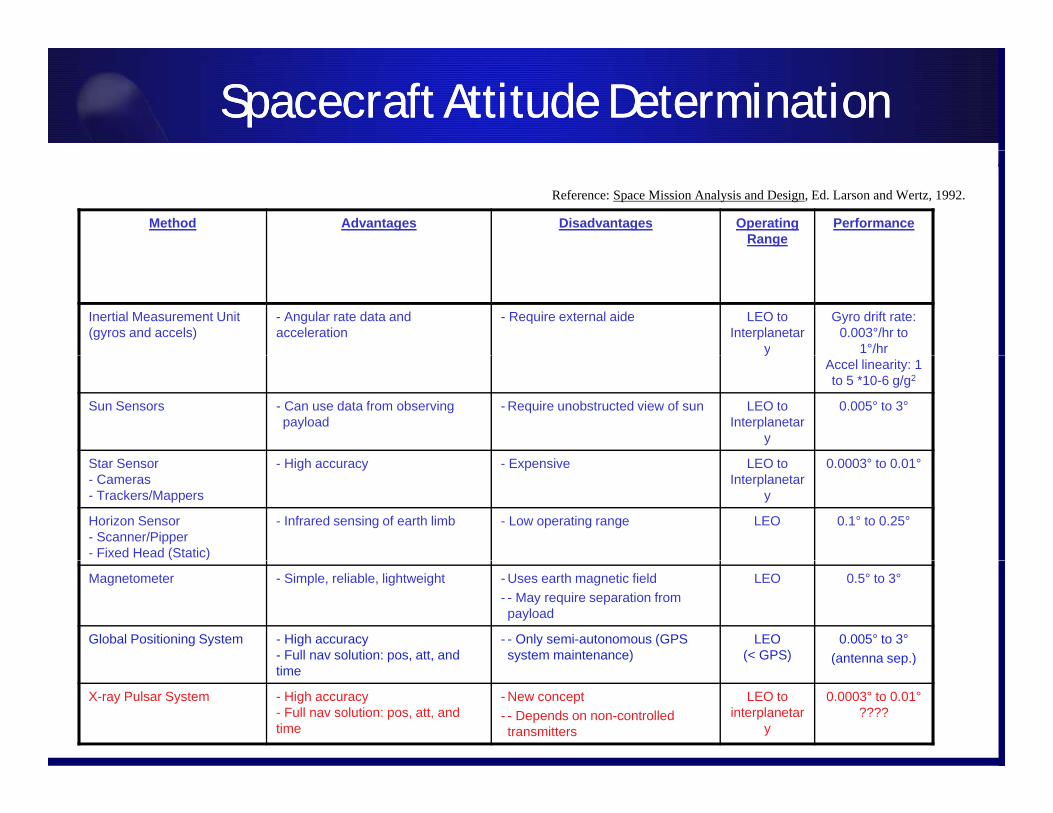
Spacecraft Attitude DeterminationSpacecraft Attitude Determination
Method Advantages Disadvantages Operating Range
Performance
Reference: Space Mission Analysis and Design, Ed. Larson and Wertz, 1992.
Inertial Measurement Unit (gyros and accels)
- Angular rate data and acceleration
- Require external aide LEO to Interplanetar
y
Gyro drift rate: 0.003°/hr to
1°/hryAccel linearity: 1 to 5 *10-6 g/g2
Sun Sensors - Can use data from observing payload
- Require unobstructed view of sun LEO to Interplanetar
y
0.005° to 3°
Star Sensor- Cameras- Trackers/Mappers
- High accuracy - Expensive LEO to Interplanetar
y
0.0003° to 0.01°
Horizon Sensor- Scanner/Pipper- Fixed Head (Static)
- Infrared sensing of earth limb - Low operating range LEO 0.1° to 0.25°
Magnetometer - Simple, reliable, lightweight - Uses earth magnetic field- - May require separation from payload
LEO 0.5° to 3°
Global Positioning System - High accuracy- Full nav solution: pos, att, and
- - Only semi-autonomous (GPS system maintenance)
LEO(< GPS)
0.005° to 3°(antenna sep.)
time( p )
X-ray Pulsar System - High accuracy- Full nav solution: pos, att, and time
- New concept- - Depends on non-controlled transmitters
LEO to interplanetar
y
0.0003° to 0.01°????
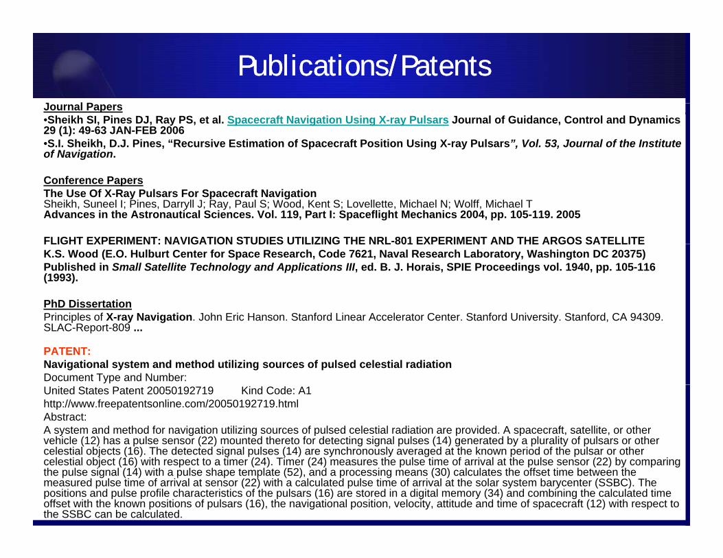
Publications/PatentsPublications/PatentsJ l PJournal Papers•Sheikh SI, Pines DJ, Ray PS, et al. Spacecraft Navigation Using X-ray Pulsars Journal of Guidance, Control and Dynamics 29 (1): 49-63 JAN-FEB 2006•S.I. Sheikh, D.J. Pines, “Recursive Estimation of Spacecraft Position Using X-ray Pulsars”, Vol. 53, Journal of the Institute of Navigation.
Conference PapersThe Use Of X-Ray Pulsars For Spacecraft Navigation Sheikh, Suneel I; Pines, Darryll J; Ray, Paul S; Wood, Kent S; Lovellette, Michael N; Wolff, Michael T Advances in the Astronautical Sciences. Vol. 119, Part I: Spaceflight Mechanics 2004, pp. 105-119. 2005
FLIGHT EXPERIMENT: NAVIGATION STUDIES UTILIZING THE NRL-801 EXPERIMENT AND THE ARGOS SATELLITEFLIGHT EXPERIMENT: NAVIGATION STUDIES UTILIZING THE NRL 801 EXPERIMENT AND THE ARGOS SATELLITEK.S. Wood (E.O. Hulburt Center for Space Research, Code 7621, Naval Research Laboratory, Washington DC 20375)Published in Small Satellite Technology and Applications III, ed. B. J. Horais, SPIE Proceedings vol. 1940, pp. 105-116 (1993).
PhD DissertationP i i l f X N i ti J h E i H St f d Li A l t C t St f d U i it St f d CA 94309Principles of X-ray Navigation. John Eric Hanson. Stanford Linear Accelerator Center. Stanford University. Stanford, CA 94309. SLAC-Report-809 ...
PATENT:Navigational system and method utilizing sources of pulsed celestial radiationDocument Type and Number:United States Patent 20050192719 Kind Code: A1 http://www.freepatentsonline.com/20050192719.html Abstract:A system and method for navigation utilizing sources of pulsed celestial radiation are provided. A spacecraft, satellite, or other vehicle (12) has a pulse sensor (22) mounted thereto for detecting signal pulses (14) generated by a plurality of pulsars or other celestial objects (16). The detected signal pulses (14) are synchronously averaged at the known period of the pulsar or otherj ( ) g p ( ) y y g p pcelestial object (16) with respect to a timer (24). Timer (24) measures the pulse time of arrival at the pulse sensor (22) by comparing the pulse signal (14) with a pulse shape template (52), and a processing means (30) calculates the offset time between the measured pulse time of arrival at sensor (22) with a calculated pulse time of arrival at the solar system barycenter (SSBC). Thepositions and pulse profile characteristics of the pulsars (16) are stored in a digital memory (34) and combining the calculated time offset with the known positions of pulsars (16), the navigational position, velocity, attitude and time of spacecraft (12) with respect to the SSBC can be calculated.
Summary• XNAV provides a autonomous navigation capability for DoD
missions:• Not instantaneous like GPS. Requires long term observations
(100s to 1000s seconds)• Superior alternative to optical star cameras
• Higher accuracy due to extremely short wavelengths (sub-arcseconds)
• Inherently radiation hardened due to their relatively large feature sizes, making them useful in high radiation environments.C b bli d d b l /S /M /E h i• Cannot be blinded by laser/Sun/Moon/Earth crossings, eliminating need for keep out zones.
• Low risk of damage by contaminants (X-rays get through)Ti b tt i l t t i t i l k• Time accuracy better or equivalent to cesium atomic clocks
• Supports future growth in non-LEO DoD assets• Has lead to a revolution in spacecraft position, attitude and time
determination (Europe, Russia, and China).
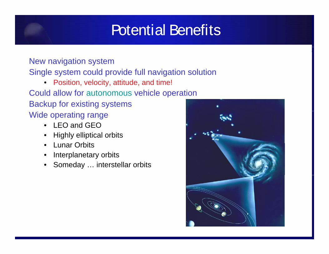
Potential BenefitsPotential Benefits
New navigation systemSingle system could provide full navigation solution
• Position, velocity, attitude, and time!Could allow for autonomous vehicle operationBackup for existing systemsWide operating range
• LEO and GEO• Highly elliptical orbits
L O bit• Lunar Orbits• Interplanetary orbits • Someday … interstellar orbits
XTIMXTIM
X-ray Timing SystemDerek Trouneaur
• Goals: create a universal timescale, Pulsar Time. • Benefits:Benefits:
• Stability: Slave an atomic clock to an ensemble of pulsars over long observation times (weeks to months)
• Autonomy: independent precise measurement of time NoAutonomy: independent precise measurement of time. No regular communication with other assets.
• Universality: Celestial sources making them available to any user Could be used to correlate events measured between twouser. Could be used to correlate events measured between two s/c.