
X-ray Magnetic Resonance Fusion to Internal Markers and Utility in Congenital Heart...
36
X-ray Magnetic Resonance Fusion to Internal Markers and Utility in Congenital Heart Disease Catheterization Dori et al: New XMRF Method and Clinical Utility Yoav Dori, MD, PhD From the Department of Cardiology, The Children’s Hospital of Philadelphia, Philadelphia, PA Marily Sarmiento, MSEE, MBA From Siemens Healthcare, Malvern, PA Andrew C. Glatz, MD; Matthew J. Gillespie, MD; Virginia M. Jones, RN, BSN; Matthew A. Harris, MD; Kevin K. Whitehead, MD, PhD; Mark A. Fogel, MD; Jonathan J. Rome, MD From the Department of Cardiology, The Children’s Hospital of Philadelphia, Philadelphia, PA Correspondence to: Yoav Dori MD PhD 34 th Street and Civic Center Boulevard Philadelphia, PA 19104 Phone: 267-426-9202 Fax: 215-590-5415 E-mail: [email protected] Journal Subject Codes: 30, 124 A A A A PA A A A A A A From Siemens Healthcare Malvern PA G R M From Siemens Healthcare, Malvern, PA Glatz, MD; Matth ew J. Gillespie, MD; Virginia M. Jones, R Matthew A. Harris, MD; Kevin K. Whitehead, MD, PhD; by guest on June 29, 2018 http://circimaging.ahajournals.org/ Downloaded from by guest on June 29, 2018 http://circimaging.ahajournals.org/ Downloaded from by guest on June 29, 2018 http://circimaging.ahajournals.org/ Downloaded from
Transcript of X-ray Magnetic Resonance Fusion to Internal Markers and Utility in Congenital Heart...

X-ray Magnetic Resonance Fusion to Internal Markers and Utility in
Congenital Heart Disease Catheterization
Dori et al: New XMRF Method and Clinical Utility
Yoav Dori, MD, PhD
From the Department of Cardiology, The Children’s Hospital of Philadelphia,
Philadelphia, PA
Marily Sarmiento, MSEE, MBA
From Siemens Healthcare, Malvern, PA
Andrew C. Glatz, MD; Matthew J. Gillespie, MD; Virginia M. Jones, RN, BSN;
Matthew A. Harris, MD; Kevin K. Whitehead, MD, PhD;
Mark A. Fogel, MD; Jonathan J. Rome, MD
From the Department of Cardiology, The Children’s Hospital of Philadelphia,
Philadelphia, PA
Correspondence to: Yoav Dori MD PhD 34th Street and Civic Center Boulevard Philadelphia, PA 19104 Phone: 267-426-9202 Fax: 215-590-5415 E-mail: [email protected]
Journal Subject Codes: 30, 124
A A A A A
PAAAAAAAFrom Siemens Healthcare Malvern PA
G R
M
From Siemens Healthcare, Malvern, PA
Glatz, MD; Matthew J. Gillespie, MD; Virginia M. Jones, R
Matthew A. Harris, MD; Kevin K. Whitehead, MD, PhD;
by guest on June 29, 2018http://circim
aging.ahajournals.org/D
ownloaded from
by guest on June 29, 2018
http://circimaging.ahajournals.org/
Dow
nloaded from
by guest on June 29, 2018http://circim
aging.ahajournals.org/D
ownloaded from

Abstract
Background X-ray magnetic resonance fusion (XMRF) allows for utilization of 3D
data during cardiac catheterization. However, to date, technical requirements have
limited the use of this modality in clinical practice. Here we report on a new internal
marker XMRF method that we have developed and describe how we used XMRF during
cardiac catheterization in congenital heart disease.
Methods and Results XMRF was performed in a phantom and in 23 patients presenting
for cardiac catheterization who also needed cardiac MRI for clinical reasons. The
registration process was performed in less than 5 minutes per patient with minimal
radiation (0.004 – 0.024 mSv) and without contrast. Registration error was calculated in
a phantom and in 8 patients using the maximum distance between angiographic and 3D
model boundaries. In the phantom the measured error in the AP projection had a mean of
1.15 mm (standard deviation 0.73). The measured error in patients had a median of 2.15
mm (IQR 1.65 – 2.56 mm). Internal markers included bones, airway, image artifact,
calcifications, and the heart and vessel borders. The MRI data was used for road
mapping in 17/23 (74%) cases and camera angle selection in 11/23 (48%) cases.
Conclusions Internal markers based registration can be performed quickly, with
minimal radiation, without the need for contrast, and with clinically acceptable accuracy
using commercially available software. We have also demonstrated several potential
uses for XMRF in routine clinical practice. This modality has the potential to reduce
radiation exposure and improve catheterization outcomes.
Key Words: x-ray magnetic resonance fusion, magnetic resonance imaging, registration,
catheterization
r patient with mimmmmmm
ation nnnn nn erererererererrororororororor r rrrrr wawawawawawawasss s s s s ccccccc
n 8 patients using the maximum distance between angiograph
e h
r
nd the heart and vessel borders The MRI data was used for r
n 8 patients using the maximum distance between angiograph
es. In the phantom the measured error in the AP projection h
rd deviation 0.73). The measured error in patients had a me
2.56 mm). Internal markers included bones, airway, image
nd the heart and vessel borders The MRI data was used for r
by guest on June 29, 2018http://circim
aging.ahajournals.org/D
ownloaded from
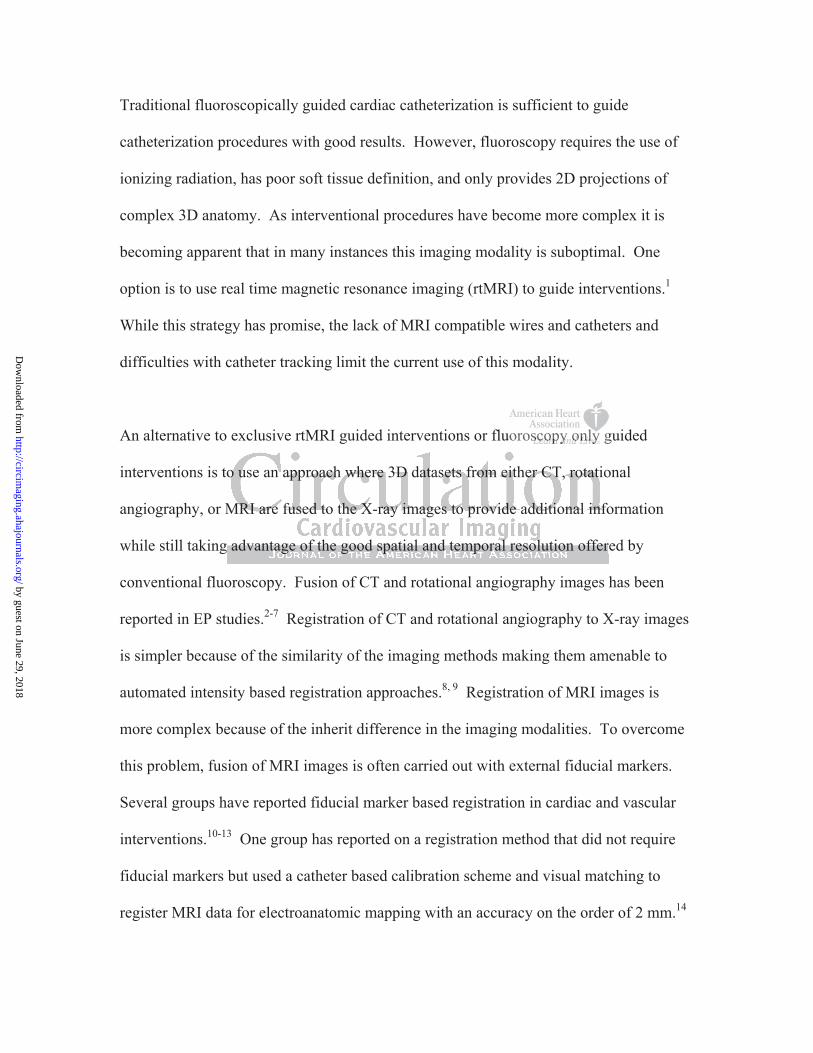
Traditional fluoroscopically guided cardiac catheterization is sufficient to guide
catheterization procedures with good results. However, fluoroscopy requires the use of
ionizing radiation, has poor soft tissue definition, and only provides 2D projections of
complex 3D anatomy. As interventional procedures have become more complex it is
becoming apparent that in many instances this imaging modality is suboptimal. One
option is to use real time magnetic resonance imaging (rtMRI) to guide interventions.1
While this strategy has promise, the lack of MRI compatible wires and catheters and
difficulties with catheter tracking limit the current use of this modality.
An alternative to exclusive rtMRI guided interventions or fluoroscopy only guided
interventions is to use an approach where 3D datasets from either CT, rotational
angiography, or MRI are fused to the X-ray images to provide additional information
while still taking advantage of the good spatial and temporal resolution offered by
conventional fluoroscopy. Fusion of CT and rotational angiography images has been
reported in EP studies.2-7 Registration of CT and rotational angiography to X-ray images
is simpler because of the similarity of the imaging methods making them amenable to
automated intensity based registration approaches.8, 9 Registration of MRI images is
more complex because of the inherit difference in the imaging modalities. To overcome
this problem, fusion of MRI images is often carried out with external fiducial markers.
Several groups have reported fiducial marker based registration in cardiac and vascular
interventions.10-13 One group has reported on a registration method that did not require
fiducial markers but used a catheter based calibration scheme and visual matching to
register MRI data for electroanatomic mapping with an accuracy on the order of 2 mm.14
oroscscscscscscs opopopopopopopy y y y y y y onononononononlylylylylylyly g
o o
M o
advantage of the good spatial and temporal resolution off r
o use an approach where 3D datasets from either CT, rotatio
MRI are fused to the X-ray images to provide additional info
advantage of the good spatial and temporal resolution offer
by guest on June 29, 2018http://circim
aging.ahajournals.org/D
ownloaded from

Accurate registration of MRI data to rotation angiography volumes has also been reported
in neurological interventions.15
In this paper we report on an internal marker XMRF method that we have developed that
does not require contrast or external fiducial markers, requires only minimal radiation
exposure, and can be done with commercially available software making it feasible to
now perform XMRF on a routine clinical basis. We then describe some of the uses we
found for this modality during cardiac catheterization in congenital heart disease.
Methods
Patient selection
XMRF was performed on patients presenting to our catheterization laboratory between
3/1/10 and 8/1/10 who also needed cardiac MRI for clinical reasons or who had
undergone MRI examination in the past year. In this study we did not target a specific
patient population and only excluded patients who had contraindicating findings on MRI
such as significant artifact from metallic devices.
MRI
MRI scans were performed on a Magnetom Avanto 1.5 T Siemens scanner. All patients
underwent cardiac MRI consisting of (1) balanced steady-state free precession (bright
blood) transverse stack which extended from the thoracic inlet to the superior portion of
the liver , (2) half-Fourier single-shot turbo spin-echo (dark blood) transverse stack
spanning the same region, (3) balanced steady-state free precession cine imaging
o r
0 h
ormed on patients presenting to our catheterization laborator
0 who also needed cardiac MRI for clinical reasons or who h
by guest on June 29, 2018http://circim
aging.ahajournals.org/D
ownloaded from

including a 2 chamber view, 4 chamber view, and short axis stack for anatomy and to
quantify ventricular function, (4) velocity-encoded cine (VEC) imaging of the ascending
aorta, vena cava, pulmonary arteries, and in some cases pulmonary veins for flow
quantification, and (5) Angiography High Spatial and Temporal Resolution MRA (syngo
TWIST) of the heart and great vessels for anatomy. Typical imaging parameters are
listed in Table 1. The images were then electronically transmitted to the workstation in
the fluoroscopy suite for review and rendering. The sequences that were selected for
registration were volume rendered and cropped using the syngo InSpace workstation.
For phantom experiments MRI scanning consisted of a balanced steady-state free
precession (bright blood) transverse stack of the phantom and Angiography High Spatial
and Temporal Resolution MRA imaging of the phantom without contrast injection.
XMRF protocol
XMRF procedures were performed using a Siemens Axiom Artis cardiac X-Ray system
connected by a Miyabi sliding table to the MRI scanner (Siemens, Erlangen, Germany).
In cases where MRI and catheterization were performed sequentially, the patients were
positioned on the Miyabi sliding table prior to the MRI procedure by the cathlab staff.
Patients that were small (usually age < 4) received general endotracheal anesthesia and
were positioned on the Miyabi table with arms elevated during both procedures. Larger
patients received conscious sedation and were positioned with the arms down during the
MRI scan. The arms were elevated after transfer to the cathlab prior to the registration
process. Patients were transferred to the X-ray room after completing the MRI study by
means of the sliding table. In those cases where the two studies were done separately the
ced steady staaaaaaatetettttt
d Angngngngngngngioioioioioioiogrgrgrgrgrgrgrapapapapapapaphyhyhyhyhyhyhy H
e jesolution MRA imaging of the phantom without contrast inj
by guest on June 29, 2018http://circim
aging.ahajournals.org/D
ownloaded from

patients were positioned on the MRI and X-ray table in the normal fashion making sure
that the patients were supine and aligned along the long axis of the table during both
procedures. The patients were then moved to isocenter, and a rotational angiography spin
was performed without using radiation (blank spin). This produces a parameter file
containing the bed and gantry coordinates and the dimensions of a theoretical X-ray
space derived from geometrical considerations. This file was then used for the first step
of the registration process.
Registration
The image registration protocol is shown in Figure 1. Image registration was carried out
with the commercially available ‘Siemens syngo InSpace 3D/3D fusion’, ‘iPilot
dynamic’, and ‘register to patient’ functionalities (Siemens, Erlangen, Germany). The
syngo InSpace 3D/3D fusion functionality was used for the first portion of the
registration process, which is divided into two steps. First the software uses an automatic
linear transformation algorithm to translate the MRI coordinate system into the X-ray
space and to scale the MRI dataset. This step, which is essential for completion of the
fusion process, does not utilize any of the rotational angiography pixel information but
rather is based solely on geometric considerations derived from the gantry and table
position when the patient’s region of interest is in isocenter. Normally, 3D rotational
angiography pixel information is present from a radio-contrast spin, allowing for the
second step which involves either automatic intensity based registration or visual
matching manual registration of the 3D angiography pixel data to the 3D MRI data.
However, in the method we have developed, since the rotational angiography spins were
regisisisisisisi ttttttrararararararatititititiitiononononononon w w wwwwwasa
r
egister to patient’ functionalities (Siemens, Erlangen, Germ
D/3D fusion functionality was used for the first portion of th
rcially available ‘Siemens syngo InSpace 3D/3D fusion’, ‘iP
egister to patient’ functionalities (Siemens, Erlangen, Germ
D/3D fusion functionality was used for the first portion of th
by guest on June 29, 2018http://circim
aging.ahajournals.org/D
ownloaded from

acquired with blocked radiation that do not contain any pixel information, the second
3D/3D registration step was bypassed. Consequently, an additional step was needed to
accurately register the MRI data. This was achieved using the ‘register to patient’ and
‘iPilot dynamic’ functionalities, which have algorithms to automatically register the live
2D fluoroscopy image to the 3D data set in any camera angel and also allows for
visualization and fading between the live 2D and 3D data sets as well as having
functionalities for 2D/3D visual matching manual registration. In the current software
version only the AP camera is registered. The manual registration step involves
translation along the three spatial coordinates of the internal marker of choice as seen on
the MRI image to match the internal marker as seen on the X-ray image. Two orthogonal
maximal field of view fluoroscopy images, one in the AP projection (0 degrees) and the
second with the AP camera in the lateral projection (90 degrees) were used for this
purpose. Upon completion of the registration process the fused 3D MRI and live
fluoroscopy images were displayed during the catheterization using ‘iPilot dynamic’,
which was also used to correct for mis-registration due to patient motion.
Patients were meticulously positioned before both procedures so that rotation of the MRI
volume was not needed. Once the registration process was completed all sequences from
the MRI scan were registered as well and all the sequences were registered to the camera
and to the table so that rotation of the camera or movement of the table produced an
equivalent movement in the registered MRI volume (Figure 1 bottom).
marker of choioiiiiiicecccccc
-ray y y y y y y imimimimimimmagagagagagagage.e.e.e.e.e.e. T T T T T T Twowwwww
f e
A fo
c d
f view fluoroscopy images, one in the AP projection (0 degre
AP camera in the lateral projection (90 degrees) were used fo
completion of the registration process the fused 3D MRI and
by guest on June 29, 2018http://circim
aging.ahajournals.org/D
ownloaded from
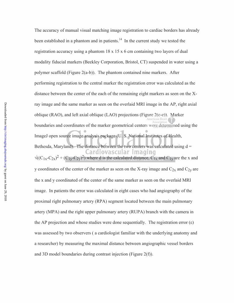
The accuracy of manual visual matching image registration to cardiac borders has already
been established in a phantom and in patients.14 In the current study we tested the
registration accuracy using a phantom 18 x 15 x 6 cm containing two layers of dual
modality fiducial markers (Beekley Corporation, Bristol, CT) suspended in water using a
polymer scaffold (Figure 2(a-b)). The phantom contained nine markers. After
performing registration to the central marker the registration error was calculated as the
distance between the center of the each of the remaining eight markers as seen on the X-
ray image and the same marker as seen on the overlaid MRI image in the AP, right axial
oblique (RAO), and left axial oblique (LAO) projections (Figure 2(c-e)). Marker
boundaries and coordinates of the marker geometrical centers were determined using the
ImageJ open source image analysis package (U. S. National Institutes of Health,
Bethesda, Maryland). The distance between the two centers was calculated using d =
((C1x-C2x)2 + (C1y-C2y)2) where d is the calculated distance, C1x and C1y are the x and
y coordinates of the center of the marker as seen on the X-ray image and C2x and C2y are
the x and y coordinated of the center of the same marker as seen on the overlaid MRI
image. In patients the error was calculated in eight cases who had angiography of the
proximal right pulmonary artery (RPA) segment located between the main pulmonary
artery (MPA) and the right upper pulmonary artery (RUPA) branch with the camera in
the AP projection and whose studies were done sequentially. The registration error ( )
was assessed by two observers ( a cardiologist familiar with the underlying anatomy and
a researcher) by measuring the maximal distance between angiographic vessel borders
and 3D model boundaries during contrast injection (Figure 2(f)).
gure 2(c e)). MMMMMMMa
s weeeeererererererere dededededededetetetetetetetermrmrmrmrmrmrmiiiiinini
rce image analysis package (U. S. National Institutes of Hea
a u
a
rce image analysis package (U. S. National Institutes of Hea
and). The distance between the two centers was calculated u
C1y-C2y)2) where d is the calculated distance, C1x and C1y a
by guest on June 29, 2018http://circim
aging.ahajournals.org/D
ownloaded from

Registration was performed to internal markers including the heart and vessel borders,
bones, conduit calcification, imaging artifact, and airway. Registration to bone was
performed with a T1 weighted short stack (3-5 slices, TR 2000, TE 45, inversion time
900, slice thickness 3 mm, bandwidth 500, matrix 256 x 256, flip angel 150, FOV 200 x
200) of either the sternum and anterior aspect of the rib cage or the spine and posterior rib
cage (Figure 3(a-h)). Registration to the airway was done with a dark blood short stack
(3-4 slices, 3 mm per slice) centered on the carina (Figure 3(i-l)). Artifacts included
susceptibility artifact from sternal wires and stents (Figure 4(a-d)). Registration was also
performed to a ring of calcification in the distal end of a right ventricle to pulmonary
artery (RV-PA) conduit (Figure 4(e-f)). Registration to the heart and vessel borders was
performed with either volume rendered MRI (VRT) images or maximal intensity
projection (MIP) rendered MRI images showing the largest cross section of the heart and
great vessels in the AP projection (Figure 5).
Statistical methods
Summary data are presented as frequency with percentage of total for count data, median
with range for non-normally distributed continuous variables, and mean with standard
deviation for normally distributed continuous variables.
This study was conducted with approval from our Institutional Review Board (IRB # 10-
007587).
t ventricle to pppppppuuluuuuu
eart t anananananannd d ddddd vevevevevevevesssssssssssssseleleeleee b
e n
t
h
either volume rendered MRI (VRT) images or maximal inten
rendered MRI images showing the largest d cross section of t
he AP projection (Figure 5).
by guest on June 29, 2018http://circim
aging.ahajournals.org/D
ownloaded from
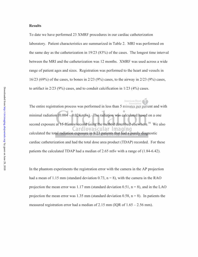
Results
To date we have performed 23 XMRF procedures in our cardiac catheterization
laboratory. Patient characteristics are summarized in Table 2. MRI was performed on
the same day as the catheterization in 19/23 (83%) of the cases. The longest time interval
between the MRI and the catheterization was 12 months. XMRF was used across a wide
range of patient ages and sizes. Registration was performed to the heart and vessels in
16/23 (69%) of the cases, to bones in 2/23 (9%) cases, to the airway in 2/23 (9%) cases,
to artifact in 2/23 (9%) cases, and to conduit calcification in 1/23 (4%) cases.
The entire registration process was performed in less than 5 minutes per patient and with
minimal radiation (0.004 – 0.024 mSv). The radiation was calculated based on a one
second exposure at 15 frames/second using the method described elsewhere.16 We also
calculated the total radiation exposure in 8/23 patients that had a purely diagnostic
cardiac catheterization and had the total dose area product (TDAP) recorded. For these
patients the calculated TDAP had a median of 2.65 mSv with a range of (1.84-6.42).
In the phantom experiments the registration error with the camera in the AP projection
had a mean of 1.15 mm (standard deviation 0.73, n = 8), with the camera in the RAO
projection the mean error was 1.17 mm (standard deviation 0.51, n = 8), and in the LAO
projection the mean error was 1.35 mm (standard deviation 0.58, n = 8). In patients the
measured registration error had a median of 2.15 mm (IQR of 1.65 – 2.56 mm).
minututututututu eseseseseseses p p p p pppererererererer p p p ppppatatataaaatiei
n
t n
n (0.004 – 0.024 mSv). The radiation was calculated based
at 15 frames/second using the method described elsewhere.
tal radiation exposure in 8/23 patients that had a purely diagn
by guest on June 29, 2018http://circim
aging.ahajournals.org/D
ownloaded from

XMRF was mainly used for roadmapping and for camera angel selection. In 17/23 cases
the overlaid images were utilized for roadmapping during the procedure. Roadmaps for
the entire catheterization procedure were created prior to the start of the catheterization
and stored as a collection of bookmarks that were retrieved when the structure of interest
was reached. An example of how XMRF was used for roadmapping is depicted in Figure
6. Whole volume rendered images or images that were cut to delineate certain structures
were utilized for this purpose (Figure 6(a-c)). The figure shows the heart of a patient
with a small RV-PA conduit and left pulmonary artery (LPA) stenosis. A coronal cut-
plane was created prior to the catheterization and used as a roadmap for navigation from
the inferior vena cave (IVC) to the conduit (Figure 6(b), 6(e)). After entering the conduit
an oblique cut-plane showing the LPA was loaded and used as a roadmap to enter the
LPA (Figure 6(c), 6(f)). In 10/23 cases it was felt that the anatomic structures of interest
would not have easily been entered without the roadmap unless contrast injection was
performed. In those cases where devices were placed the XMRF roadmaps were used
for preliminary device positioning although in all instances final device positions were
performed based on contrast angiograms.
Camera angle selection based on the MRI data was performed in 11/23 cases (Table 3).
The relevant anatomic information was obtained by viewing the 3D reconstructed image
from different angles and then choosing the camera angle that would best profile the
structure of interest. The camera was then rotated to the desired position and the fused
image reviewed to assure that there was nothing on the fluoroscopy image that could
interfere with the angiogram and to confirm that the chosen angle produced the desired
oadmap for navavavvvvvii
). AfAfAfAfAfAfA teteteteteteter rr rrrr enenenenenenenteteteteteteteririririririringn
lane showing the LPA was loaded and used as a roadmap to
) r
e c
lane showing the LPA was loaded and used as a roadmap to
), 6(f)). In 10/23 cases it was felt that the anatomic structur
easily been entered without the roadmap unless contrast injec
by guest on June 29, 2018http://circim
aging.ahajournals.org/D
ownloaded from

result. In the majority of these cases it was felt that the 3D anatomy would not have
been obtained by a single contrast injection using conventional camera angles (Figure 7).
Although not a major focus of this work we also used the non fused 3D MRI anatomical
data prior to the catheterization procedures to perform preliminary catheter and device
selection and sizing based on MRI measurements. An example demonstrating how the
non fused 3D MRI anatomical data was used is shown in Figure 8. The figure depicts a
case with stenosis in the proximal pulmonary arteries and the proximal RV-PA conduit.
After reviewing the MRI data we determined that three stents would be needed each with
a different length and diameter.
Discussion
The syngo InSpace 3D/3D fusion functionality was designed to enable accurate
registration of previously acquired MRI data to 3D syngo rotational angiography datasets.
However, this requires a significant amount of radiation and contrast making it
impractical for routine use in children. Here we report on a method we have developed
to perform the registration process using the same commercially available software tools
but with minimal radiation and without the need for contrast injection making it feasible
to perform XMRF on a routine clinical basis. Furthermore, we have shown that the
registration in a phantom and in patients is accurate with error values similar to those that
have been previously reported.14
s would be neeeeeeeeddddddd
a race 3D/3D fusion functionality was designed to enable accur
by guest on June 29, 2018http://circim
aging.ahajournals.org/D
ownloaded from

The current registration software requires that we perform a blank spin to acquire the
table coordinates and the dimensions of the X-ray space. However, in practice this step
could be easily eliminated because the registration parameters are derived exclusively
from geometrical consideration, such as the geometry of the gantry and the relative table
position, that are fixed once the patient is placed in isocenter. Furthermore, the
registration parameters for all possible camera angles can be derived from similar
geometrical considerations, which will likely increase the accuracy of the registration
process in off axis (steep) camera angels. Although, at more extreme camera angles other
factors affecting the X-ray beam, such as X-ray beam distortion, also need to be
considered.
Rigid body registration algorithms result in an MRI volume whose shape is fixed in time.
In reality, there are non periodic changes in the geometry of the heart and vessels due to
physiological factors, such as change in preload, and due to distortion of the vessel
conformation by stiff wires and catheters (Figure 8(c)). In addition, there are periodic
changes from respiratory and cardiac motion that produce a time varying registration
error. The magnitude of the periodic errors in most cases does not exceed the error
tolerance for most of the interventions we encounter in CHD. In contrast, the non
periodic errors, especially those due to anatomy distortion by stiff wires and catheters,
can be significant limiting the utility of this modality in certain situations. In these cases
non rigid registration algorithms would need to be employed.
ion, also needd t ttttttoo
t f
a s
tration algorithms result in an MRI volume whose shape is f
are non periodic changes in the geometry of the heart and ves
by guest on June 29, 2018http://circim
aging.ahajournals.org/D
ownloaded from

Fiducial marker based registration has been shown to be accurate to high spatial
resolution under certain conditions but this method has several drawbacks. First, it
requires that the MRI scan immediately precede catheterization as the markers need to
remain attached during both procedures. Second, skin mobility and movement of internal
organs relative to the skin can make this method inaccurate. Third, the need to include
the markers in the MRI images requires a larger scanned volume increasing imaging time
and could result in reduced imaging resolution. Fourth, fiducial markers can interfere
with the catheterizers view and obstruct important structures during contrast angiograms.
Last, fiducial marker based registration requires propriety software that is not currently
commercially available.
Internal marker based registration offers several advantages over fiducial marker based
registration. Internal markers are inherently more stable. They allow for easy correction
of patient motion and they do not interfere with contrast angiograms. Furthermore,
internal marker based registration alleviates the constraint imposed by fiducial marker
based registration namely the need to perform the MRI and the catheterization
successively. In this study the heart and vessel borders were the most frequently used
markers. In addition, we report on registration to other possible internal markers as a
proof of concept and to show the generalizability of our methodology. In two cases
where the heart and vessel borders were not clearly visible due to the presence of
significant pulmonary edema registration was done to the airway. Registration to the
imaging artifact, stent, and calcification were easy to implement and subjectively
accurate, but although more common in pediatric patients, these markers are not routinely
ftware that is nonononononono
b a
e s
based registration offers several advantages over fiducial ma
ernal markers are inherently more stable. They allow for eas
by guest on June 29, 2018http://circim
aging.ahajournals.org/D
ownloaded from

present. In addition, the flexibility of our methodology allows for switching between
MRI volumes and markers quickly as well as for using multiple markers simultaneously.
MRI is able to provide diagnostic quality 3D images in most cases even in the present of
metallic artifact. In contrast to rotational angiography or CT, MRI does not require
ionizing radiation and it provides hemodynamic data. Furthermore, the 3D anatomy of
the entire circulatory system is obtained with a single contrast injection allowing us to
roadmap the entire procedure and select camera angels for all vessels prior to the start of
the procedure. However, there are certain conditions, such as in the presence of
epicardial pacemaker leads or stainless steel coils, where MRI is either contraindicated or
non-diagnostic. In these cases other modalities like CT or rotational angiography can be
used if 3D data are needed.16
The ability to roadmap without the need for contrast offers a distinct advantage in certain
cases because contrast is known to significantly affect hemodynamics. Furthermore, the
ability to roadmap the entire procedure and store the roadmaps as bookmarks has the
potential to save time, reduce radiation exposure and contrast load. But, there are two
limitations to this roadmapping modality that need to be considered. First, the spatial
resolution of MRI is on the order of one millimeter making contrast injections necessary
for roadmapping in very small vessels. Second, as previously mentioned the presence of
stiff wires or catheters can significantly alter the geometry of the vessels making
roadmapping based on previously acquired images inaccurate.
s in the presennnnnnncceccccc
RI is eieieieieieieithththththththererererererer cc c ccccononononononontrtra
I r
a
In these cases other modalities like CT or rotational angiogr
are needed.16
by guest on June 29, 2018http://circim
aging.ahajournals.org/D
ownloaded from

In all cases where the non fused 3D MRI anatomical data was used for initial
approximate sizing of devices, the actual final device sizing was obtained from
measurements performed on contrast angiograms. Care needs to be taken in trying to
size devices based on MRI data. The diameter of vessels in volume rendered datasets
highly depends on thresholding levels and is consequently not reliable.17 Sizing from
non-contrast images, such as cine or bright blood images is potentially more accurate
however, one needs to take into account that the MRI images are averaged over multiple
heart cycles and not obtained instantaneously as is the case in angiography. In contrast to
device diameter, sizing of device lengths can be more reliably determined from volume
rendered MRI data as this dimension is less dependent on rendering levels. Further
studies will need to be conducted to determine if accurate sizing of devices based on MRI
image can be reliably done.
The TDAP that we calculated in this study is lower than the results reported in the
literature by Bacher et al. of 4.6 mSv with range (0.6 - 23.2) for all types of congenital
heart disease diagnostic procedures.18 However, certain limitations in the study make it
impossible to say with certainty if these results are significant. First, in this study we
only had a small number of patients with each type of disease and of those only a small
number that had purely diagnostic procedures. Second, because we only studied patients
that needed both a catheterization and MRI there is a significant selection bias in the
cases that we evaluated. Last, in this study there was a large variation in patient size and
age. Further studies will need to be conducted to determine the true effect of the XMRF
modality on radiation exposure.
y determined fffffffrorrrrrr
ndeririiiiiingngngngngngng l l l l l levevevevevevevelelelelelelels.s.s.s.s.s.s. F
d b
i
d to be conducted to determine if accurate sizing of devices bf
iably done.
by guest on June 29, 2018http://circim
aging.ahajournals.org/D
ownloaded from

In this study we describe the new XMRF method that we have developed and show how
the XMRF modality can be utilized during cardiac catheterization. In addition, the
substantial hemodynamic and 3D anatomic information obtained from the MRI scans
could allow us to plan the catheterization and may allow us to performed a more targeted
catheterization aimed at only obtaining missing information. Further studies are currently
underway to determine the effect of this modality on catheterization outcomes.
Limitations of current study
In this study we describe the XMRF registration process and retrospectively discuss our
early experience with this new modality in a relatively small number of patients and as
such has several inherit limitations. Because of the way patients were selected there may
be significant selection bias. The clinical portion of the study is descriptive in nature, as
such we cannot draw definitive conclusions about the effect of this modality on
catheterization outcomes. In particular our assessments of the advantage we derived
from XMRF in specific cases were inherently subjective.
In patients the registration error was calculated only in the AP projection during one
phase of the cardiac cycle. Although we did perform angiograms in other angles and
have subjectively seen accurate registration in off axis angles the small number of
overlaid angiograms at each angle does not allow us to comment on the accuracy of the
registration in all angles. However, it is likely that the registration error will increase
with steeper camera angels. We can also not comment on the dependence of the error on
retroroooooosssssspepepepepepepectctctctctctctivivivivivivivelelelelelelelyy yyy
e
e
l i
with this new modality in a relatively small number of patie
inherit limitations. Because of the way patients were selecte
lection bias. The clinical portion of the study is descriptive i
by guest on June 29, 2018http://circim
aging.ahajournals.org/D
ownloaded from

the temporal proximity of the MRI and catheterization studies as most of the MRI and
catheterization cases were performed on the same day, and although we demonstrated the
feasibility of using internal markers other than the heart and vessel borders, the small
number of cases that were performed using these markers make it impossible to comment
on the accuracy of the registration to each of the different markers. In addition, in this
work we did not account for periodic changes from respiratory and heart motion in the
error calculation. In reality, these factors produce a time varying error (t) that would
need to be calculated using more elaborate methods. Further studies will need to be
conducted to determine how these different factors affect the registration process and
utility.
Conclusions
XMRF to internal markers can be performed quickly, with clinically acceptable accuracy,
without the need for contrast, with minimal radiation exposure and using commercially
available software tools making it feasible to now perform XMRF on a routine clinical
basis. XMRF was used for camera angle selection, preliminary device positioning, and
for roadmapping. This modality has the potential to reduce radiation exposure and
improve catheterization outcomes.
registration ppppppprorororrorr
a bal markers can be performed quickly, with clinically acceptab
by guest on June 29, 2018http://circim
aging.ahajournals.org/D
ownloaded from

Disclosures
None.
References 1. Saikus CE, Lederman RJ. Interventional cardiovascular magnetic resonance
imaging: A new opportunity for image-guided interventions. JACC Cardiovasc Imaging. 2009;2:1321-1331
2. Knecht S, Skali H, O'Neill MD, Wright M, Matsuo S, Chaudhry GM, Haffajee CI, Nault I, Gijsbers GH, Sacher F, Laurent F, Montaudon M, Corneloup O, Hocini M, Haissaguerre M, Orlov MV, Jais P. Computed tomography-fluoroscopy overlay evaluation during catheter ablation of left atrial arrhythmia. Europace. 2008;10:931-938
3. Sra J, Krum D, Malloy A, Vass M, Belanger B, Soubelet E, Vaillant R, Akhtar M. Registration of three-dimensional left atrial computed tomographic images with projection images obtained using fluoroscopy. Circulation. 2005;112:3763-3768
4. Sra J, Narayan G, Krum D, Akhtar M. Registration of 3d computed tomographic images with interventional systems: Implications for catheter ablation of atrial fibrillation. J Interv Card Electrophysiol. 2006;16:141-148
5. Sra J, Narayan G, Krum D, Malloy A, Cooley R, Bhatia A, Dhala A, Blanck Z, Nangia V, Akhtar M. Computed tomography-fluoroscopy image integration-guided catheter ablation of atrial fibrillation. J Cardiovasc Electrophysiol. 2007;18:409-414
6. Li JH, Haim M, Movassaghi B, Mendel JB, Chaudhry GM, Haffajee CI, Orlov MV. Segmentation and registration of three-dimensional rotational angiogram on live fluoroscopy to guide atrial fibrillation ablation: A new online imaging tool. Heart Rhythm. 2009;6:231-237
7. Orlov MV. How to perform and interpret rotational angiography in the electrophysiology laboratory. Heart Rhythm. 2009;6:1830-1836
8. Tomazevic D, Likar B, Pernus F. 3-d/2-d registration by integrating 2-d information in 3-d. IEEE Trans Med Imaging. 2006;25:17-27
9. Tomazevic D, Likar B, Slivnik T, Pernus F. 3-d/2-d registration of ct and mr to x-ray images. IEEE Trans Med Imaging. 2003;22:1407-1416
10. de Silva R, Gutierrez LF, Raval AN, McVeigh ER, Ozturk C, Lederman RJ. X-ray fused with magnetic resonance imaging (xfm) to target endomyocardial injections: Validation in a swine model of myocardial infarction. Circulation. 2006;114:2342-2350
11. Gutierrez LF, Ozturk C, McVeigh ER, Lederman RJ. A practical global distortion correction method for an image intensifier based x-ray fluoroscopy system. MedPhys. 2008;35:997-1007
12. Gutierrez LF, Silva R, Ozturk C, Sonmez M, Stine AM, Raval AN, Raman VK, Sachdev V, Aviles RJ, Waclawiw MA, McVeigh ER, Lederman RJ. Technology
eeeeeeelelelelelelelet t tttt t E,E,E,E,E,E,E, V V VVV V Vaiaiaiaiaiaiaillllllllllllllananananananantttt tt RRRRRRRd tomomomomomomomogrgrgrgrgrgrgrapapapapapapaphihihihihihihic c c c c c c imim
n images obtained using fluoroscopy. Ci l ti . 2005 112r o
w nor
V gatheter ablation of atrial fibrillation J Cardiovasc Electrophy
n images obtained using fluoroscopy. Circulation. 2005;112rayan G, Krum D, Akhtar M. Registration of 3d computed to
with interventional systems: Implications for catheter ablationon. J Interv Card Electrophysiol. 2006;16:141-148rayan G, Krum D, Malloy A, Cooley R, Bhatia A, Dhala A,
V, Akhtar M. Computed tomography-fluoroscopy image integatheter ablation of atrial fibrillation J Cardiovasc Electrophy
by guest on June 29, 2018http://circim
aging.ahajournals.org/D
ownloaded from

preview: X-ray fused with magnetic resonance during invasive cardiovascular procedures. Catheter Cardiovasc Interv. 2007;70:773-782
13. Rhode KS, Hill DL, Edwards PJ, Hipwell J, Rueckert D, Sanchez-Ortiz G, Hegde S, Rahunathan V, Razavi R. Registration and tracking to integrate x-ray and mr images in an xmr facility. IEEE Trans Med Imaging. 2003;22:1369-1378
14. Ector J, De Buck S, Adams J, Dymarkowski S, Bogaert J, Maes F, Heidbuchel H. Cardiac three-dimensional magnetic resonance imaging and fluoroscopy merging: A new approach for electroanatomic mapping to assist catheter ablation. Circulation. 2005;112:3769-3776
15. Levitt MR, Ghodke BV, Cooke DL, Hallam DK, Kim LJ, Sekhar LN. Endovascular procedures with cta and mra roadmapping. J Neuroimaging. 2010 Jul 23. [Epub ahead of print]
16. Glatz AC, Zhu X, Gillespie MJ, Hanna BD, Rome JJ. Use of angiographic ct imaging in the cardiac catheterization laboratory for congenital heart disease. JACC Cardiovasc Imaging. 2010;3:1149-1157
17. Valverde I, Parish V, Hussain T, Rosenthal E, Beerbaum P, Krasemann T. Planning of catheter interventions for pulmonary artery stenosis: Improved measurement agreement with magnetic resonance angiography using identical angulations. Catheter Cardiovasc Interv. 2011;77:400-408
18. Bacher K, Bogaert E, Lapere R, De Wolf D, Thierens H. Patient-specific dose and radiation risk estimation in pediatric cardiac catheterization. Circulation. 2005;111:83-89
ry stenosis: Impmpmpmpmpmpmpgigigigigigigiogogogogogogogrararararararaphphphphphphphy y y y y y y usususususususinininininnngg g g g g g 0-4008 8 88 8 88
K, Bogaert E, Lapere R, De Wolf D, Thierens H. Patient-specfK, Bogaert E, Lapere R, De Wolf D, Thierens H. Patient-specfrisk estimation in pediatric cardiac catheterization. Circulat:83-89
by guest on June 29, 2018http://circim
aging.ahajournals.org/D
ownloaded from

Table 1. List of MRI typical imaging parameters.
Bright blood (SSFP)
Dark blood (SE)
Cine (SSFP)
VEC Twist
TR 120 800 30 30 2.5
TE 1.2 20 1.5 2.5 1
BW 1200 800 1200 400 800
ST (mm) 3 3 4-6 4-5 1.5
flip angel 90 180 90 25 25
matrix 100x128 100x128 128x176 128x176 192x192
FOV 150x200 150x200 190x220 150x200 200x300
BW - bandwidth, ST - slice thickness, VEC - velocity encoded phase contrast, FOV - field of view.
200000000
xxxxxxx171717171717176 6 666 66 191919191919192x2x2x2x2x2x2x1111111
202020202020200000000 33
rtv
50x200 150x200 190x220 150x200 200x350x200 150x200 190x220 150x200 200x3
th, ST - slice thickness, VEC - velocity encoded phase contrview.
by guest on June 29, 2018http://circim
aging.ahajournals.org/D
ownloaded from

Table 2. Summary of patient characteristics. Demographics data are reported as median
with range and anatomical category data are reported as frequency with percentage of
total count.
Characteristic n=23
Demographics:
Gender male 14/23 (61%)
Age (years) 3.59 (0.4-43.8)
Weight (kg) 13.7 (3.6-90.1)
Height (cm) 86 (25.2-169.4)
Anatomic Category:
Glenn 7/23 (31%)
TGA 1/23 (4%)
Truncus 3/23 (13%)
Fontan 3/23 (13%)
TOF 8/23 (35%)
DILV 1/23 (4%)
TGA - transposition of the great arteries, TOF - Tetralogy of Fallot, DILV - double inlet left ventricle.
)g ( ) ( )
/ ( )
g ( ) ( )
Anatomic Category:
Glenn 7/23 (31%)
TGA 1/23 (4%)
/ ( )
by guest on June 29, 2018http://circim
aging.ahajournals.org/D
ownloaded from
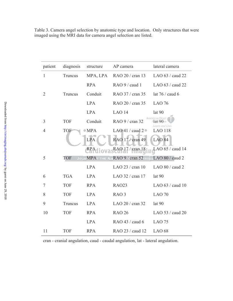
Table 3. Camera angel selection by anatomic type and location. Only structures that were imaged using the MRI data for camera angel selection are listed.
patient diagnosis structure AP camera lateral camera
1 Truncus MPA, LPA RAO 20 / cran 13 LAO 63 / caud 22
RPA RAO 9 / caud 1 LAO 63 / caud 22
2 Truncus Conduit RAO 37 / cran 35 lat 76 / caud 6
LPA RAO 20 / cran 35 LAO 76
LPA LAO 14 lat 90
3 TOF Conduit RAO 9 / cran 32 lat 90
4 TOF MPA LAO 41 / caud 2 LAO 118
LPA RAO 17 / cran 49 LAO 84
RPA RAO 17 / cran 18 LAO 65 / caud 14
5 TOF MPA RAO 9 / cran 52 LAO 80 / caud 2
LPA LAO 23 / cran 10 LAO 80 / caud 2
6 TGA LPA LAO 32 / cran 17 lat 90
7 TOF RPA RAO23 LAO 63 / caud 10
8 TOF LPA RAO 3 LAO 70
9 Truncus LPA LAO 20 / cran 32 lat 90
10 TOF RPA RAO 26 LAO 53 / caud 20
LPA RAO 43 / caud 6 LAO 75
11 TOF RPA RAO 23 / caud 12 LAO 68
cran - cranial angulation, caud - caudal angulation, lat - lateral angulation.
lalalalalalalat t ttttt 90909090909090
T
T / d
a
aTOF MPA RAO 9 / cran 52
TOF MPA LAO 41 / caud 2 LAO 118
LPA RAO 17 / cran 49 LAO 84
RPA RAO 17 / cran 18 LAO 65 / ca
LAO 80 / ca
by guest on June 29, 2018http://circim
aging.ahajournals.org/D
ownloaded from

Figure Legends
Figure 1 illustrates the XMRF registration protocol. The images at the bottom of the
figure show the result of the registration process as seen with the AP camera in the AP
(bottom left) projection and with the AP camera rotated to the lateral projection (bottom
right).
Figure 2 illustrates the method used for error calculation. Figure 2(a-b) show the volume
rendered MRI image of the phantom in the AP and lateral projections. Figure 2(c)
depicts the AP projection of four dual modality markers enclosed by the box in (a) fused
to the X-ray image. In 2(d) a magnified view of a overlaid marker is seen. In 2(e) the
same marker is seen with a light blue dashed line surrounding the marker as seen on the
MRI image and a yellow solid line surrounding the same marker as seen on the X-ray
image. The error was calculated as the distance between the center of the two circular
regions (light green bar). Figure 2(f) depicts contrast injection into the proximal RPA
with an insert showing a magnified view of the RPA. The yellow arrow points to the
location where the error was measured and the green bar indicates the magnitude of the
error at this location.
Figure 3 shows XMRF to the spinal cord 2(a-d), sternum 2(e-h), and the airway 2(i-l).
Figures 4(a-b) show XMRF to imaging artifact from sternal wires that resulted in indents
on a RV-PA conduit. In Figures 4(c-d) susceptibility artifact from a stent produced a gap
ojections. Figggggggururuuuuu
osed d d d d dd bybybybybybyby t t t t t tthehehehehehehe b bbbbbboxoxooooo
g
a t
ge. In 2(d) a magnified view of a overlaid marker is seen. I
een with a light blue dashed line surrounding the marker as
a yellow solid line surrounding the same marker as seen on t
by guest on June 29, 2018http://circim
aging.ahajournals.org/D
ownloaded from

in the MRI image of the LPA in a patient with a Glenn shunt. The insert in image 4d
shows a close up view of the stent registered between the two PA stumps. Figures 4(e-f)
depicts registration to distal conduit calcification. The arrow in figure 4(e) points
toward a ring of calcification that formed at the distal end of a RV-PA conduit. All
images are in the AP projection.
Figure 5 depicts XMRF to heart and vessel borders using volume rendered MRI (VRT)
image 5(b) and maximal intensity projection (MIP) rendered image showing the largest
cross sectional of the heart and great vessels 5(c). In 5(a) the dashed line traces the heart
border and the left lateral border of the aorta on the X-ray image. Figures 5(d-e) show
the registered VRT and MIP images. All images are in the AP projection.
Figure 6 depicts images of a patient with a small RV-PA conduit that were stored as a
collection of bookmarks for roadmapping 6(a-c) and the same images during the
catheterization process 6(d-f). In 6(b) the pathway from the IVC to the entrance to the
conduit is shown (dashed arrow) on an image that was created with an AP cut plane. The
corresponding catheter course is shown in 6(e). Figure 6(c) shows a roadmap image that
was created with an oblique cut plane exposing the PA confluence and a hypoplastic
LPA. The corresponding catheter course with the tip of the catheter positioned in the
distal LPA is shown in 6(f).
Figure 7 demonstrates how camera angle selection was utilized in a patient with complex
PA anatomy. In this case the LPA originated from the proximal RPA and immediately
dashed line trtrrrrrracaaaaaa
age. . F FFFFFFigigigigigigigururururururureseseseseseses 5 555555(d(
R
t
RT and MIP images. All images are in the AP projection.
images of a patient with a small RV-PA conduit that were st
by guest on June 29, 2018http://circim
aging.ahajournals.org/D
ownloaded from

took a 90 degree turn as it headed to the left. There was also proximal LPA hypoplasia.
Figures 7(a-d) correspond to the AP camera and 7(e-h) to the lateral camera. The
anatomy is show in the conventional camera angles 7(a-b, e-f) and in the angle that was
chosen for the contrast angiogram 7(c) and 7(g). The corresponding contrast angiograms
are shown in 7(d) and 7(h).
Figure 8 shows the anatomy of a patient with an RV-PA conduit and bilateral proximal
branch pulmonary artery stenosis (yellow arrows). The volume rendered MRI images
8(a-b) show the three stenotic regions. Figure 8(c) was taken after a Palmaz XL 40 mm
x 10 mm stent (Cordis) was placed using a 18 x 3.5 BiB (NuMed Inc.) balloon in the
proximal conduit (cyan arrow), a Genesis 3910B stent (Cordis) was placed with a 10x3.5
BiB in the proximal RPA (red arrow), and simultaneously, a Genesis 2910B stent was
placed using a 12x3 BiB in the proximal LPA (light green arrow). Figure 8(c) also
illustrates an example of a non periodic error due to distortion of the distal RPA by a stiff
wire resulting in the wire appearing to be outside of the vessel (light blue arrow).
n after a Palmmmazazaaaaa
Meddddddd I I I I I I Incncncncncncnc.).).).).).).) b b b b b bbalalalalalalallololololololoo
t w
m
2 c
t (cyan arrow), a Genesis 3910B stent (Cordis) was placed w
mal RPA (red arrow), and simultaneously, a Genesis 2910B
2x3 BiB in the proximal LPA (light green arrow). Figure 8(c
by guest on June 29, 2018http://circim
aging.ahajournals.org/D
ownloaded from

by guest on June 29, 2018http://circim
aging.ahajournals.org/D
ownloaded from

by guest on June 29, 2018http://circim
aging.ahajournals.org/D
ownloaded from

by guest on June 29, 2018http://circim
aging.ahajournals.org/D
ownloaded from

by guest on June 29, 2018http://circim
aging.ahajournals.org/D
ownloaded from

by guest on June 29, 2018http://circim
aging.ahajournals.org/D
ownloaded from

by guest on June 29, 2018http://circim
aging.ahajournals.org/D
ownloaded from

by guest on June 29, 2018http://circim
aging.ahajournals.org/D
ownloaded from

by guest on June 29, 2018http://circim
aging.ahajournals.org/D
ownloaded from
Harris, Kevin K. Whitehead, Mark A. Fogel and Jonathan J. RomeYoav Dori, Marily Sarmiento, Andrew C. Glatz, Matthew J. Gillespie, Virginia M. Jones, Matthew A.
CatheterizationX-ray Magnetic Resonance Fusion to Internal Markers and Utility in Congenital Heart Disease
Print ISSN: 1941-9651. Online ISSN: 1942-0080 Copyright © 2011 American Heart Association, Inc. All rights reserved.
TX 75231is published by the American Heart Association, 7272 Greenville Avenue, Dallas,Circulation: Cardiovascular Imaging
published online May 2, 2011;Circ Cardiovasc Imaging.
http://circimaging.ahajournals.org/content/early/2011/04/29/CIRCIMAGING.111.963868World Wide Web at:
The online version of this article, along with updated information and services, is located on the
http://circimaging.ahajournals.org/content/suppl/2011/04/29/CIRCIMAGING.111.963868.DC1Data Supplement (unedited) at:
http://circimaging.ahajournals.org//subscriptions/
is online at: Circulation: Cardiovascular Imaging Information about subscribing to Subscriptions:
http://www.lww.com/reprints Information about reprints can be found online at: Reprints:
document. Permissions and Rights Question and Answer this process is available in the
located, click Request Permissions in the middle column of the Web page under Services. Further information aboutnot the Editorial Office. Once the online version of the published article for which permission is being requested is
can be obtained via RightsLink, a service of the Copyright Clearance Center,Circulation: Cardiovascular Imaging Requests for permissions to reproduce figures, tables, or portions of articles originally published inPermissions:
by guest on June 29, 2018http://circim
aging.ahajournals.org/D
ownloaded from

Supplemental Material
Video1.movThe movie depicts a registered MRI volume following the C-arm as it is rotated from the lateral to the anterior-posterior (AP) projection of a patient with Tetralogy of Fallot with pulmonary atresia and an apical muscular ventricular septal defect status post device closure.
Video2.movThis movie was taken in a patient with a complex RV to PA conduit, two large aorto-pulmonary collateral vessels from the descending aorta to the RPA, and a hypoplastic LPA and left lung. Prior to the catheterization bookmarks were created for navigation to the conduit and to the LPA using cut planes through the MRI volume. Contrast injections in the proximal conduit, LPA, and RPA confirm the accuracy of the MRI overlay.