X-BT - Hilti - Eesti Applications 7 2. APPLICATIONS 2.1 Grating fastening system (X-BT M8-15-6...
88
X-BT Hilti X-BT Threaded Fastener Specification July 2015 *) *) Updated editorially March 2017
Transcript of X-BT - Hilti - Eesti Applications 7 2. APPLICATIONS 2.1 Grating fastening system (X-BT M8-15-6...

X-BTHilti X-BT Threaded Fastener Specification
July 2015 *)*) Updated editorially March 2017

2 Contents
1. Introduction page 4 1.1 Definitions and general terminology 4 1.2 The X-BT system 4 1.3 X-BT system features and benefits – simplified fastening to steel 5 1.4 Installation method and anchoring mechanism 6 1.5 X-BT and X-BT-ER applications 6 2. Applications page 7 2.1 Grating fastening system 7 2.2 X-BT and MQ installation channel system 9 2.3 Fastening instrumentation, junction boxes and lighting 10 2.4 Fastening cable/conduit connectors 11 2.5 Fastening cable tray supports 11 2.6 X-BT for fastening and connecting earthing devices 12 2.6.1 Functional bonding and terminal connection in a circuit 12 2.6.2 Protective bonding circuit 12-13 2.6.3 Lightning protection 13
3. Technical data page 14 3.1 Product data 14 3.1.1 Material specifications 14 3.1.2 Fastening tool 14 3.1.3 Approvals 15 3.2 Load data 16 3.2.1 Loads - steel base material 16 3.2.2 Loads - cast iron base material 16-17 3.3 Application requirements and limits 17 3.3.1 Thickness of fastened material - X-BT 17 3.3.2 Thickness of cable lug - X-BT-ER 17 3.3.3 Spacing and edge distance 17 3.3.4 Application limit/thickness of base material 17 3.3.5 Fastener selection 18 3.3.6 Cartridge selection and tool energy setting 18 3.3.7 Installation details - X-BT 18 3.3.8 Installation for electrical connections - X-BT-ER 19 3.3.9 Fastening quality assurance 19
4. Method statement page 20 4.1 Instructions for use - X-BT M6/W6 SN12-R 20 4.2 Instructions for use - X-BT M8/M10/W10 SN12-R 20 4.3 Instructions for use - X-BT-ER M6/W6/M8 21 4.4 Instructions for use - X-BT-ER M10/W10 21

Contents
Contents 3
5. Performance (technical reports) page 22 5.1 Nomenclature and symbols / design concepts 22-23 5.2 Static capacity of the X-BT threaded stud 24 5.2.1 Tensile load deformation behavior of the
X-BT threaded stud fastenings 24 5.2.2 Pullout strength of X-BT threaded stud fastenings 25 5.2.3 Shear strength of X-BT threaded stud fastenings 26 5.2.4 Effect of edge distance/spacing on pull-out strength
of X-BT fastenings 27-28 5.2.5 Holding mechanisms X-BT threaded stud fastenings 29 5.3 Corrosion resistance 30 5.3.1 X-BT threaded stud fastening corrosion data 30-31 5.3.2 Contact corrosion – X-BT stainless steel
stud in carbon steel 32 5.3.3 Corrosion data from field tests at Helgoland
island (North Sea) 33 5.4 Effect of X-BT threaded stud fastenings on steel base material 34 5.4.1 Fatigue classification in compliance with Eurocode 3 35 5.4.2 Approved fatigue categories by GL and DNV 36-37 5.5 Technical data for X-BT fastenings made to cast iron with spheroidal graphite 38 5.5.1 Cast iron specification 38 5.5.2 Grounding and bonding restrictions 38 5.5.3 Performance review 39-40 5.6 Vibration effects on X-BT threaded stud fastenings 41 5.7 Temperature resistance of X-BT threaded stud fastenings 42-43 5.8 X-BT-ER stainless steel threaded studs electrical performances 44 5.8.1 Contact resistance 44 5.8.2 Effect of X-BT-ER fasteners on integrity of pipe flange 44 5.8.3 Permanent current 45 5.8.4 Short circuit current 46-47 5.8.5 Lightning current 48 5.9 X-BT in stainless steel base material 49 5.10 X-BT under shock loading 50 5.11 X-BT stud in steel with a thickness of less than 8 mm 51 5.11.1 Pull-out capacity in thin steel 51 5.11.2 Shear load capacity in thin steel 51-52 5.11.3 X-BT electrical conductivity in thin steel 52 5.12 Chemical resistance of SN 12 sealing washer 53 5.13 Material safety data sheet of SN 12 sealing washer 54-60
6. Approvals page 62 6.1 American Bureau of Shipping (ABS) 62-64 6.2 Lloyd’s Register 65-66 6.3 DNV-GL 67-70 6.4 Russian Maritime Register 71-72 6.5 Bureau Veritas (BV) 73-76 6.6 ICC Evaluation Services (ICC-ES) 77-84
7. Customer testimonials page 86
4 Introduction
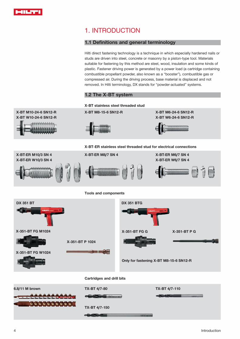
1. INTRODUCTION1.1 Definitions and general terminology
Hilti direct fastening technology is a technique in which especially hardened nails or studs are driven into steel, concrete or masonry by a piston-type tool. Materials suitable for fastening by this method are steel, wood, insulation and some kinds of plastic. Fastener driving power is generated by a power load (a cartridge containing combustible propellant powder, also known as a “booster”), combustible gas or compressed air. During the driving process, base material is displaced and not removed. In Hilti terminology, DX stands for “powder-actuated” systems.
1.2 The X-BT system
X-BT stainless steel threaded stud
X-BT-ER stainless steel threaded stud for electrical connections
Tools and components
Cartridges and drill bits
X-BT M10-24-6 SN12-RX-BT W10-24-6 SN12-R
X-BT-ER M10/3 SN 4X-BT-ER W10/3 SN 4
X-BT M8-15-6 SN12-R
X-BT-ER M8/7 SN 4
X-351-BT FG M1024
DX 351 BT
X-351-BT FG W1024
X-351-BT P 1024
X-351-BT FG G
DX 351 BTG
Only for fastening X-BT M8-15-6 SN12-R
X-351-BT P G
X-BT M6-24-6 SN12-RX-BT W6-24-6 SN12-R
X-BT-ER M6/7 SN 4X-BT-ER W6/7 SN 4
6.8/11 M brown TX-BT 4/7-80
TX-BT 4/7-150
TX-BT 4/7-110

Introduction
Introduction 5
1.3 X-BT system features and benefits – simplified fastening to steel
No reworkStud welding or through-bolting, for example, may require reworking of the protec-tive surface coating. With X-BT, the stud is set into a small pre-drilled hole and the drill entry point is then completely sealed by the stud washer during setting.
Simple and fastA minimal amount of training is all that’s required for a user to be able to drive up to 100 studs per hour.
High corrosion resistanceX-BT studs are made of high grade A4 (316 SS equivalent) stainless steel, making them the right choice for almost every corrosive environments.
High loading and pull-out valuesX-BT delivers performance comparable to methods such as stud welding.
Fasten to all steel shapesUnlike clamps, which are limited by the configuration of the base steel, the X-BT is ideal for use on hollow sections, channel sections, wide flanges and angles.
Fasten to all steel gradesIn addition to fastening to standard construction steel, the X-BT can also be used to fasten to high strength and thick steel.
PortableThe fastening tool’s self-contained energy source eliminates the need for electrical cords and heavy welding equipment.
No through-penetrationThe special process of drilling and driving results in secure fastening of the stud without through-penetration of the base material.
Rework
Corrosion
Loosening
Through-penetration

Introduction
6 Introductions
1.4 Installation method and anchoring mechanism
The blunt-tipped fastener X-BT with a shank diameter of 4.5 mm is driven in a pre-drilled 4.0 mm diameter hole. This leads to displacement of the base material. Part of the base steel is punched down into the pre-drilled hole, generating high temperatures and causing friction welding. Due to elasticity of the base steel, additional clamping effects are also superposed. Displaced base material can be clearly seen in the photograph. Base material adhering to the fastener shank indicates a welding effect.(For more details regarding installation, please refer to Part 4 – Method statement)
1.5 X-BT and X-BT-ER applications
Metal / fiberglass grating to steel for upstream and high corrosion environment
Mechanical and electrical for petro chemical industry, shipbuilding, etc.
Fastening Hilti MQ installation channel system, metal brackets, clips, metal tracks, etc. to steel
Functional and protective bonding and lightning protection
X-BT-ER M10X-BT-ER W10X-BT-ER M8X-BT-ER M6X-BT-ER W6
X-BT M10X-BT W10X-BT M8X-BT M6X-BT W6
X-BT M8 +X-FCM-R
X-BT M10X-BT W10X-BT M6X-BT W6

Applications
Applications 7
2. APPLICATIONS2.1 Grating fastening system(X-BT M8-15-6 SN12-R and X-FCM-R)
An all stainless steel fastening system designed for attaching metal and fiber-glass grating to coated steel and/or high-strength steel
L
HG
8m
m[ 5
/16"
]
o 18.5
o 52 [2.047"]
8.6
[ 0.3
39"]
o 10.3
L +
4L
1.6
19.5
16
5 [0.197"]
HILTI
[0.782"]
[0.406"]
[ 0.6
30"]
[ 0.7
68"]
[ 0.1
57"]
[ 0.0
63"]
X-FCM-R grating disc
Important: The X-FCM-R system is not designed or intended to resist shear loads.
X-SEA-R 30 M8 extension adaptorFor use with X-FCM-R grating fasteners for fastening of grating with a height in excess of 50 mm/1.97 in.
Fastener selection
Designation L (mm/in.) Grating height, HG, range (mm/in.)
Grating height with X-SEA-R 30 M8
X-FCM-R 25/30 23/0.91 25–30/0.98–1.18 55–60/2.16–2.36X-FCM-R 1"–1¼" 27/1.06 29–34/1.14–1.34 59–64/2.32–2.52X-FCM-R 35/40 33/1.30 35–40/1.38–1.57 65–70/2.56–2.75X-FCM-R 45/50 43/1.69 45–50/1.77–1.97 75–80/2.91–3.15

8 Applications
Installation details
Hand start to ensure no cross threading, then tighten using screwdriver with torque clutch.
Tightening torque: 5–8 Nm [3.7–5.9 ft-lb]
Tightening tool:• Screwdriver with torque release coupling (TRC)• 5 mm Allen-type bit
Hilti screwdriver Torque settingSF 121-A 6 - 10SF 150-A 5 - 8SF 14 5 - 8SF 14-A 6 - 10SF 18-A 5 - 8SFC 18-A 5 - 8SF 22-A 5 - 8
Installation instructions
1 2 3.0
43.1 5
Pre-drill until shoulder grinds a shiny ring.The drill hole and the area around drilled hole must be clean and free from liquids and debris.
Drive fastener only with DX 351 BT G tool and 6.8/11M brown cartridge.
Tighten X-FCM-R with 5 mm Allen-type bit.
Lay grating section in final position.
Expand grating openings if necessary.
Pre-drill with TX-BT 4/7 step shank drill bit.

Applications
Applications 9
2.2 X-BT and MQ installation channel system
MQ installation channel on coated steel (electrical installation and small-bore piping)
Note: In case of applied shear load, the X-BT should be placed according to illus-tration (end of slotted hole)
Two X-BT studs in one slotted hole One X-BT stud in each slotted hole
Fastening MQ brackets and bases for raised floor

10 Applications
2.3 Fastening instrumentation, junction boxes and lighting
X-BT stainless steel threaded stud for attaching instrumentation, junction boxes and lighting to coated steel and high-strength steel
Installation instructions
Drive X-BT studs with DX 351 BT tool and X-BT cartridge.
Position unit on studs and hold in place. Fit washers and start tightening by hand to avoid cross threading.
Tighten using a screwdriver with torque clutch. (Trec ≤ 8 Nm / 5.9 ft-Ib)
Mark location of each fastening.
Pre-drill with TX-BT 4/7 step shank drill bit.
Pre-drill until shoulder grinds a shiny ring.The drill hole and the area around drilled hole must be clean and free from liquids and debris.
1 2.0 2.1
3 4 5

Applications
Applications 11
2.4 Fastening cable/conduit connectors
X-BT threaded stud for cable/conduit connectors.Stainless steel threaded stud for fastening cable and conduit connectors (T-bars) to coated steel and/or high-strength steel
Installation instructions
1 2.0 2.1
3 4 5
Mark location of each fastening.
Pre-drill with TX-BT 4/7 step shank drill bit.
Pre-drill until shoulder grinds a shiny ring.The drill hole and the area around drilled hole must be clean and free from liquids and debris
Drive fastener only with DX 351 BT tool and 6.8/M brown cartridge.
Screw on the connector and hand tighten. (Trec ≤ 8 Nm / 5.9 ft-Ib)
Align connectors.
2.5 Fastening cable tray supports
X-BT stainless steel stud for fastening cable trays to coated and / or high-strength steel
Installation instructions
1 2

12 Applications
Fasteners
Single point connection
Single point connection
Functional and protective bonding in pipe (Outer diameter of installed surface ≥ 150mm)
Protective bonding circuit – Double point connection
X-BT-ER M10/3 SN 4X-BT-ER W10/3 SN 4
X-BT-ER M6/7 SN 4X-BT-ER W6/7 SN 4
X-BT-ER M8/7 SN 4
2.6 X-BT-ER stainless steel threaded studs for electricalconnections
2.6.2 Protective bonding circuit
For discharging short circuit current while protecting electrical equipment or earth / ground or bond cable trays and ladders.
2.6.1 Functional bonding and terminal connection in a circuit
For low permanent current due to static charge built up in pipes or for low perma-nent current when closing an electrical circuit
Recommended electrical connectors:• X-BT-ER M10/3 SN 4• X-BT-ER W10/3 SN 4• X-BT-ER M8/7 SN 4• X-BT-ER M6/7 SN 4• X-BT-ER W6/7 SN 4
Recommended electrical connectors:• X-BT-ER M10/3 SN 4• X-BT-ER W10/3 SN 4• X-BT-ER M8/7 SN 4• X-BT-ER M6/7 SN 4• X-BT-ER W6/7 SN 4
Max. short circuit current for period of 1s = 1250A
Max. allowable permanent current = 40A
Ø 1
2
[ 0
.472
"]
Ø 4
.5
[ 0
.177
"]
24 [0.945"] 4[0.158"]
4[0.158"]
2 [0.079"]
31.3 [1.232"]
3
4
65 51 27
M8
Ø 1
2[ 0
.472
"]
M10
/W
10
Ø 4
.5
[ 0
.177
"]
24 [0.945"] 5[0.197"]
5[0.197"]
2.4 [0.094"]
31.3 [1.232"]
1 2 3
4
65 5
Ø 1
2
[ 0
.472
"]
M6/
W6
Ø 4
.5
[ 0
.177
"]
20 [0.787"] 5[0.197"]
5[0.197"]
1.6[0.062"]
31.3 [1.232"]
3
4
65 571
Please refer to Part 5.8.2 for additional technical information with regards to the effect of X-BT-ER fasteners on integrity of pipe flange.
Note:• Recommended connected cable size (tested to 40A) according to IEC/EN 60204-1:
≤ 10mm2 copper (≤ 8AWG). Fastening of thicker cable is acceptable provided the maximum permanent current of 40A is not exceeded and the provisions on cable lug thickness are observed.
Note:• Recommended connected cable size (tested to 1250A for 1s) following IEC/EN
60947-7-2: ≤ 10mm2 copper (≤ 8AWG). Fastening of thicker cable is acceptable provided the maximum current of 1250A for a period of 1 second is not exceeded and the provisions on cable lug thickness are observed.
• Recommended connected cable size (tested to 750A for 4s) according to UL 467: ≤ 10AWG

Applications 13
Applications
When one nut is utilized and cable lug is in contact with base material.
• Cable lug must be in direct contact with non-coated base material.• Extra M10/W10 SS washer to be used and installed between lock washer and
cable lug.• Base material must not contact the X-BT-ER SN washer, lock washer and nut.• Cable lug thickness = 2mm to 12mm. Cable lug hole diameter ≥ 13mm.• Max. tightening torque = 8Nm.
Double-point connection
Single point connection
2.6.3 Lightning protection
For high temporary current due to lightning.
Recommended electrical connectors:• X-BT-ER M8/7 SN 4• X-BT-ER M6/7 SN 4• X-BT-ER W6/7 SN 4
Recommended electrical connectors:• X-BT-ER M10/3 SN 4• X-BT-ER W10/3 SN 4• X-BT-ER M8/7 SN 4• X-BT-ER M6/7 SN 4• X-BT-ER W6/7 SN 4
Recommended electrical connectors:• X-BT-ER M10/3 SN 4• X-BT-ER W10/3 SN 4• X-BT-ER M8/7 SN 4• X-BT-ER M6/7 SN 4• X-BT-ER W6/7 SN 4
Max. short circuit current for period of 1s = 1800A
Maximum tested current ≤ 100kA for 2ms
Maximum current (According to EN50164-1 and EN 50164-1/prA:2005):≤ 50kA for 2ms
Note:• Recommended connected cable size (tested to 1800A for 1s) following IEC/EN
60947-7-2: ≤ 16mm2 copper (≤ 6AWG). Fastening of thicker cable is acceptable provided the maximum current of 1800A for a period of 1 second is not exceeded and the provisions on cable lug thickness are observed.

14 Technical Data
3. TECHNICAL DATA3.1 Product data
3.1.1 X-BT material specifications
① Shank: CR500 (CrNiMo alloy) equivalent to A4 / AISI S31803 (1.4462) grade 316 material N 08926 (HCR, 1.4529)1) available on request② Threaded sleeve: S31609 (X5CrNiMo 17-12-2+2H, 1.4401)③ SN12-R washers: S31635 (X2CrNiMo 17-12-2, 1.4404)④ Sealing washers: Elastomer, black, resistant to UV, salt water, water, ozone,
oils, etc.⑤ Guide washer: plasticDesignation according to Unified Numbering System (UNS)1) For high corrosion resistance HCR material inquire at Hilti.
3.1.2 X-BT-ER material specifications
① Shank: CR500 (CrNiMo alloy) equivalent to A4 / AISI S31803 (1.4462) grade 316 material② Threaded sleeve: X5CrNiMo 17-12-2+2H, 1.4401③ SN12-R washers: S31635 (X2CrNiMo 17-12-2, 1.4404)④ Sealing washers: Elastomer, black, resistant to UV, salt water, water, ozone,
oils, etc.⑤ Nuts: A4 / AISI grade 316 material⑥ Lock washers: A4 / AISI grade 316 material⑦ Guide sleeve: plastic
3.1.3 Fastening tool
DX 351-BT / BTG, see fastener selection in section 3.3.5.
X-BT W10-24-6 SN12-RX-BT M10-24-6 SN12-R
X-BT M8-15-6 SN12-R X-BT W10-24-6-RX-BT M10-24-6-R
X-BT-ER M10/3 SN 4X-BT-ER W10/3 SN 4
X-BT M8-15-6-R
X-BT-ER M8/7 SN 4
X-BT W6-24-6 SN12-RX-BT M6-24-6 SN12-R
X-BT-ER M6/7 SN 4X-BT-ER W6/7 SN 4
Ø 1
2
[ 0
.472
"]
M6/
W6
Ø 4
.5
[ 0
.177
"]
20 [0.787"] 5[0.197"]
5[0.197"]
1.58 [0.062"]
31.3 [1.232"]
3
4
65 551
Ø 1
2
[ 0
.472
"]
Ø 4
.5
[ 0
.177
"]
24 [0.945"] 4[0.158"]
4[0.158"]
2 [0.079"]
31.3 [1.232"]
3
4
65 51 27
M8
Ø 1
2[ 0
.472
"]
M10
/W
10
Ø 4
.5
[ 0
.177
"]
24 [0.945"] 5[0.197"]
5[0.197"]
2.4 [0.094"]
31.3 [1.232"]
1 2 3
4
65 5
Ø 1
2
[ 0
.472
"]
M6/
W6
Ø 4
.5
[ 0
.177
"]
20 [0.787"] 5[0.197"]
5[0.197"]
1.6[0.062"]
31.3 [1.232"]
3
4
65 571
Technical Data 15
Technical Data
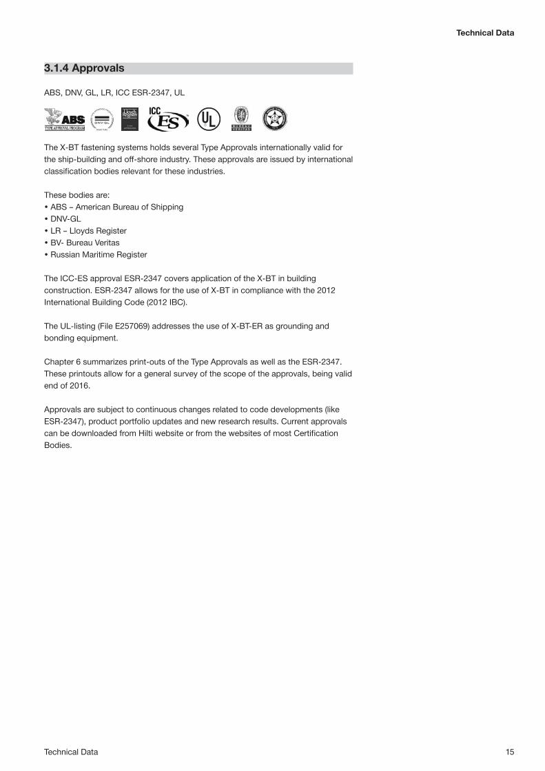
3.1.4 Approvals
ABS, DNV, GL, LR, ICC ESR-2347, UL
The X-BT fastening systems holds several Type Approvals internationally valid for the ship-building and off-shore industry. These approvals are issued by international classification bodies relevant for these industries.
These bodies are: • ABS – American Bureau of Shipping• DNV-GL• LR – Lloyds Register• BV- Bureau Veritas• Russian Maritime Register
The ICC-ES approval ESR-2347 covers application of the X-BT in building construction. ESR-2347 allows for the use of X-BT in compliance with the 2012 International Building Code (2012 IBC).
The UL-listing (File E257069) addresses the use of X-BT-ER as grounding and bonding equipment.
Chapter 6 summarizes print-outs of the Type Approvals as well as the ESR-2347. These printouts allow for a general survey of the scope of the approvals, being valid end of 2016.
Approvals are subject to continuous changes related to code developments (like ESR-2347), product portfolio updates and new research results. Current approvals can be downloaded from Hilti website or from the websites of most Certification Bodies.

16 Technical Data
3.2 Load data
3.2.1 Loads - steel base materialRecommended loads – steel base materialSteel grade: S235, S355, grade 50Europe, USA A36 and stronger steelTension, Nrec [kN/lb] 1.8 / 405 2.3 / 517Shear, Vrec [kN/lb] 2.6 / 584 3.4 / 764Moment, Mrec [Nm/ftlb] 8.2 / 6 8.2 / 6Torque, Trec [Nm/ftlb] 8 / 5.9 8 / 5.9
Conditions for recommended loads• Global factor of safety for static pull-out > 3 (based on 5% fractile value)
≥ 5 (based on mean value)• Minimum edge distance = 6 mm [1/4"].• Effect of base metal vibration and stress considered.• Redundancy (multiple fastening) must be provided.• The recommended loads in the table refer to the resistance of the individual fasten-
ing and may not be the same as the loads FN and FV acting on the fastened part.
Note: If relevant, prying forces need to be considered in design, see example. Moment acting on fastener shank only in case of a gap between base and fastened material.
Design resistance - steelSteel grade: Europe S235 S355Tension, NRd [kN] 2.9 3.7Shear, VRd [kN] 4.2 5.4Moment, MRd [Nm] 18.4 18.4
Cyclic loading• Anchorage of X-BT threaded stud in steel base material has been shown in
laboratory testing to be resistant to cyclic loading.• Fatigue strength is governed by fracture of the shank. The characteristic number
of loads cycles NK at 1.8 kN amounts to approximately 0.5 million, based on laboratory testing. Ask Hilti for more detailed test data if high cyclic loading has to be considered in the design.
3.2.2 Loads – cast iron base material*Recommended loads – cast iron base material*Tension, Nrec [kN/lb] 0.5 / 115 Shear, Vrec [kN/lb] 0.75 / 170 Moment, Mrec [Nm/ftlb] 8.2 / 6
Design resistance – cast iron*Tension, NRd [kN] 0.8 Shear, VRd [kN] 1.2 Moment, MRd [Nm] 13.1 *Requirements of spheroidal graphite cast iron base material
Subject RequirementsCast iron Spheroidal graphite cast iron according to EN 1563Strength class EN-GJS-400 to EN-GJS-600 according to EN 1563Chemical analysisand amount of carbon 3.3 - 4.0 mass percentageMicrostructure From IV to VI (spherical) according to EN ISO 945-1:2010 Minimum size 7 according to figure 4 of EN ISO 945-1:2010Material thickness tII ≥ 20 mm
V
N
M
Z3
FNFVZ1
Z2
Example:

Technical Data 17
Technical Data
3.3 Application requirements and limits
3.3.1 Thickness of fastened material - X-BT
X-BT M8: 2.0 ≤ tI ≤ 7 mmX-BT M10 / X-BT W10: 2.0 ≤ tI ≤ 15 mmX-BT M6 / X-BT W6: 1.0 ≤ tI ≤ 14 mm t N
UT
t WAS
HER t I
L g
X-BT-ER M10/W10tcl ≤ 3mm (0.12”)
X-BT-ER M8 / X-BT-ER M6/W6tcl ≤ 7mm (0.28”)
3.3.4 Application limit/thickness of base material
tII ≥ 8 mm [5/16”] → No through-penetration. No limits with regard to steel strength.
8 mm [5/16"]
Recommended interaction formula for combined loading - steel and cast iron base materialCombined loading situation Interaction formula
V–N (shear and tension) VVrec
+ NNrec
≤ 1.2 with VVrec
≤ 1.0 and NNrec
≤ 1.0
V–M (shear and bending) VVrec
+ MMrec
≤ 1.2 with VVrec
≤ 1.0 and MMrec
≤ 1.0
N–M (tension and bending) NNrec
+ MMrec
≤ 1.0
V–N–M (shear, tension and bending) VVrec
+ NNrec
+ MMrec
≤ 1.0
3.3.3 Spacing, edge distances and base material thicknessEdge distance: ≥ 6 mm Spacing: ≥ 15 mm
[1/4"][5/8"] [5/8"][1/4"]
3.3.2 Thickness of cable lug - X-BT-ER
Outer diameter of installedsurface (e.g. pipe flange) ≥150mm

18 Technical Data
3.3.5 Fastener selection
3.3.6 Cartridge selection and tool power setting
6.8/11 M high-precision brown cartridge Fine adjustment by installation tests on site
The recommended tool energy setting = 1 (if required, increase of energy setting based on job site tests).
Fastener Item number Fastening tool Fastening components Cartridge Step shank drill bit
For grating application
6.8/11 M brownHigh Precision(item no: 412689 )
TX-BT 4/7-80(item no: 377079)
TX-BT 4/7-110(item no: 377080)
TX-BT 4/7-150(item no: 377081)
X-BT M8-15-6 SN12-R 377074
Tool:DX 351 BTG
Fastener guide:X-351-BT FG G (item no: 378675)Piston:X-351-BT P G (item no: 378677)
X-BT M8-15-6-R (without washer) * 2034770Fastener guide:X-351-BT FG G (item no: 378675)Piston:X-351-BT P G (item no: 361211)
For multi-purpose fastening application
X-BT M10-24-6 SN12-R 377078
Tool: DX 351 BT
Fastener guide:X-351-BT FG M1024 (item no: 378674)
Piston:X-351-BT P 1024 (item no: 378676)
X-BT M10-24-6-R (without washer) * 2034771
X-BT M8-24-6 SN12-R ** -
X-BT M6-24-6 SN12-R 432266
X-BT W10-24-6 SN12-R 377076 Fastener guide:X-351-BT FG W1024 (item no: 378673)
Piston:X-351-BT P 1024 (item no: 378676)
X-BT W10-24-6-R (without washer) * 2034772
X-BT W6-24-6 SN12-R 432267
For electrical connection application
X-BT-ER M10/3 SN 4 2103094
Tool: DX 351 BT
Fastener guide:X-351-BT FG M1024 (item no: 378674)
Piston:X-351-BT P 1024 (item no: 378676)
X-BT-ER M8/7 SN 4 2103095
X-BT-ER M6/7 SN 4 2107275
X-BT-ER W10/3 SN 4 2103093 Fastener guide:X-351-BT FG W1024 (item no: 378673)Piston:X-351-BT P 1024 (item no: 378676)X-BT-ER W6/7 SN 4 2103096
Note: For High Corrosion Resistance HCR material inquire at Hilti (X-BT only).The three step shank drills only differ in their length. Their optimized use depends on the accessibility condition on the jobsite. X-BT-MR-N is available on request for applications in crane and machinery manufacturing. * NQA-1-2000 compliant** Please contact Hilti for availability.

Technical Data 19
Technical Data
Pre-drill until the bit shoulder grinds a shiny ring (to ensure proper drilling depth).
Tightening torque, Trec ≤ 8Nm [5.9 ft-lb]!
Hilti screwdriver Torque settingSF 121-A 11SF 150-A 9SF 180-A 8SF 144-A 9SF 22-A 9
3.3.7 Installation details - X-BT X-BT with washer Fastened material hole diameter ≥ 13 mm (> 1/2") X-BT without washer Fastened material hole diameter ≥ 11 mm (> 3/8") for X-BT M/W10 ≥ 9 mm (> 5/16") for X-BT M8X-BT M6 / X-BT W6 Fastened material with pre-drilled hole diameter < 7 mm (9/32") Fastened material with pre-drilled hole diameter ≥ 7 mm (9/32") + washer
Note: pre drill hole diameter ≤ 10 mm (3/8").
Before fastener installation The drilled hole must be clear of liquids and debris. The area around the drilled hole must be free from liquids and debris.
h NVS
3.3.9 Fastening quality assurance
Fastening inspection
X-BT M8hNVS = 15.7–16.8 mm
X-BT M10 / X-BT W10 and X-BT M6 / X-BT W6X-BT-ER M/W10, X-BT-ER M8 and X-BT-ER M/W6hNVS = 25.7 –26.8 mm
3.3.8 Installation for electrical connections - X-BT-ER
Single point connection for all X-BT-ER
Double point connection only for X-BT-ER M6/W6 and X-BT-ER M8

20 Method statement
6
7
X-BT
1
-
+8a
426375 A319.11.2015
4263
75 A
3-11
.2015
X-BT M8/M10/W10 SN12-R
3
10
8b
4
5
DX 351-BTGDX 351-BT
2
≤ 8 Nm
100x
≤ 200 N
9
X-BT M8-15-6SN12-RX-BT M10-24-6SN12-RX-BT W10-24-6SN12-R
DX 351 BTG
DX 351 BT
DX 351 BT
X BT 4000-A /SF BT 22-A / SF BT 18-A
TX-BT 4/7-110
TX-BT 4/7-80
TX-BT 4/7-80
Ø ≥13 mm ½"
2-10 mm5 ⁄64 - 3 ⁄8"
X-BT
: 26.
8 m
mX-
BT: 2
5.7m
m
X-BT
: 26.
8 m
mX-
BT: 2
5.7m
m
SF BT 22-ASF BT 18-A
SFC 14-A 6SFC 18-A 3SFC 22-A 3
Printed: 07.12.2016 | Doc-Nr: PUB / 5139154 / 000 / 01
4. METHOD STATEMENT
4.1 Instructions for use - X-BT M6/W6 SN12-R
4.2 Instructions for use - X-BT M8/M10/W10 SN12-RX-
BT: 2
6.8
mm
6
7
1
-
+8a
441636 A222.01.2015
4416
36 A
2-01
.2015
X-BT M6/W6SN12-R
3
10
8b
4
5
DX 351 BT
2
≤ 8 Nm
100x
≤ 200 N
9
X-BT
: 25.
7mm
Ø ≥13 mm 1/2"
2-10 mm5/64 - 3/8"
X-BT
: 26.
8 m
mX-
BT: 2
5.7m
m
X-BT M6-24-6SN12-R
X-BT W6-24-6SN12 -R
DX 351 BT TX-BT 4/7-80
X-BT M6/W6
SF BT 22-ASF BT 18-A
X BT 4000-A /SF BT 22-A / SF BT 18-A
SFC 14-A 6SFC 18-A 3SFC 22-A 3
Printed: 07.12.2016 | Doc-Nr: PUB / 5260598 / 000 / 00
Instructions for use are subject to continuous changes related to code developments, product portfolio updates, and new research results.Current instruction for use can be downloaded from Hilti website.

Method statement
Method statement 21
≤ 200 N
2114
473 A
5-11
.2015
2114473 A519.11.2015
X-BT-ER M10/W10
≥ 8 mm 5/16"
≤ 3 mm
DX 351 BT
100x
X-BT-ER
X-BT
: 26.
8 m
m
X-BT
: 26.
8 m
m
+
X-BT
: 25.
7 m
m
-X-
BT: 2
5.7
mm
Tinst
min. 8 Nmmax. 20 Nm
X-BT-ER M10/W10
2
3
4
9a 9b
10
11
8a
7
6
5 8b
1
SF BT 22-ASF BT 18-A
DX 351 BT
X BT 4000-A /SF BT 22-A / SF BT 18-ATX-BT 4/7-80
Printed: 07.12.2016 | Doc-Nr: PUB / 5216978 / 000 / 04
≤ 200 N
2105
086 A
5-11
.2015
2105086 A519.11.2015
X-BT-ER M6/W6/M8
X-BT-ER M6/W6 X-BT-ER M8
≥ 8 mm 5/16"
≤ 7 mm
DX 351 BT
100x
X-BT-ER
X-BT
: 26.
8 m
m
X-BT
: 26.
8 m
m+
X-BT
: 25.
7 m
m
-
X-BT
: 25.
7 m
m
Tinst
min. 8 Nmmax. 20 Nm
1
2
3
4
9a 9b
10
11
8a
7
6
5 8b
SF BT 22-ASF BT 18-A
DX 351 BT
X BT 4000-A /SF BT 22-A / SF BT 18-ATX-BT 4/7-80
Printed: 07.12.2016 | Doc-Nr: PUB / 5216976 / 000 / 03
4.3 Instructions for use - X-BT-ER M6/W6/M8
4.4 Instructions for use - X-BT-ER M10/W10
Instructions for use are subject to continuous changes related to code developments, product portfolio updates, and new research results.Current instruction for use can be downloaded from Hilti website.

22 Performance
5. PERFORMANCE (TECHNICAL REPORTS)
5.1 Nomenclature and symbols, design concepts
The symbols and nomenclature used in the technical data are listed below.
Fastener test data and performanceN and V Tensile and shear forces in a general senseF Combined force (resulting from N and V) in a general senseNs and Vs Tensile and shear forces acting on a fastening in a design calculationFs Combined force (resulting from Ns and Vs) in a design calculationNu and Vu Ultimate tensile and shear forces that cause failure of the fastening, statistically,
the reading for one specimenNu,m and Vu,m Average ultimate tensile and shear forces that cause failure of the fastening, statistically, the average for a sample of several specimensS The standard deviation of the sampleNRk and VRk Characteristic tensile and shear resistance of the fastening, statistically, the 5 %
fractile. For example, the characteristic strength of a fastening whose ultimate strength can be described by a standard Gauss type distribution is calculated by: NRk = Nu,m - k x S where k is a function of the sample size, n and the desired confidence interval.
Nrec and Vrec Recommended maximum tensile and shear loads for the fastener shank: Nrec = NRk and Vrec = VRk where is the overall factor of safety
Mrec Recommended working moment for the fastener shank Mrec = MRk where MRk is the characteristic moment resistance of the fastener
shank and is an overall factory of safety. Unless otherwise stated on the product data sheets, the Mrec values in this manual include a safety factor of “2” for static loading.
NRd and VRd Tensile and shear design force on the fastener shank
Fastening detailshET Penetration of the fastener point below the surface of the base materialhNVS Nail head standoff above the surface fastened into (with nails, this is the surface of
the fastened material, with threaded studs, the surface of the base material).tll Thickness of the base materialtl Thickness of the fastened material∑ tl Total thickness of the fastened material (where more than one layer is fastened)tcl Thickness of cable lug (for X-BT-ER)
Characteristics of steel and other metalsfy and fu Yield strength and ultimate strength of metals (in N/mm2 or MPa)

Performance
Performance 23
This summary is intended to be representative of the test(s) carried out. It is not intended to be a full and complete test report.
Working load concept
Ns ≤ Nrec = NRk
where is an overall factor of safety including allowance for:• errors in estimation of load• deviations in material and work-
manship
and Ns is, in general, a characteristic acting load.
Ns ≅ Nsk
Partial safety concept
NSd ≤ NRdNSd = NSk × NRd = NRk /
where is a partial factor of safety to allow for errors in estimation on the acting load.
is a partial factor of safety to allow for deviations in material and workmanship.
Design concepts
The recommended working loads (Nrec and Vrec) are generally suitable for use in typical working load designs.

24 Performance
This summary is intended to be representative of the test(s) carried out. It is not intended to be a full and complete test report.
5.2 Static capacity of the X-BT threaded stud
5.2.1 Tensile load deformation behavior of X-BT threadedstud fastenings
Load-displacement behavior of blunt-tip stainless steel threaded studs, Report No. XE_02_03; Reinhard Buhri; January 2002Evaluation report on 5S (X-BT)-fastenings, Report No. XE_02_36; Hermann Beck, July 2002
Base material Steel, 20mm thick, fu = 385 MPa (S235) and fu = 630 MPa (S355)Number of fastenings in test 11 (6 in S235, 5 in S355)
➊ Displacement sensor➋ Base steel➌ X-BT-M10-24-6➍ Special nut, M10➎ Loading plate
Conclusions• Very stiff up to maximum load• Significant resistance to pull-out even after relatively large displacement• Ultimate pull-out loads increase with increasing base steel strength• The continued resistance during pull-out and the dependency of ultimate pull-out
load on base steel strength indicates that the fastener fuses with the base steel
➊
➋
➊ Load-displacement curve of one speci-men selected as being representative for the five specimens tested.
➋ Load-displacement curve of one speci-men selected as being representative for the six specimens tested.
➋
➊
➌➍
➎

Performance
Performance 25
This summary is intended to be representative of the test(s) carried out. It is not intended to be a full and complete test report.
5.2.2 Pull-out strength of X-BT threaded stud fastenings
Load behavior on special steel constructions, Report No. XE_01_57; Reinhard Buhri; 30 November 2001Pull-out strength of blunt tip stainless steel threaded studs, Report No. XE_02_23; Reinhard Buhri; 9 April 2002
Base material Steel, 6, 8, 10, 12 and 15 mm thick, S235 and S355Number of fastenings in test 200 total, (20 per situation of thickness and steel grade)
Ultimate pull-out load as a function of base steel thicknessX-BT threaded studs in S235 [A36] steel
Ultimate pull-out loadas a function of base steel ultimate tensile strength
Conclusions• For steel thickness ≥ 8 mm, 5% fractile pull-out ≥ 6kN without regard to steel grade• Lower pull-out values with S235/A36• Higher pull-out values with thermomechanical hot-rolled fine-grain steel according
to ABS and EN 10025-4 and quenched and tempered high-grade steel according to EN 10025-6

26 Performance
5.2.3 Shear strength of X-BT threaded stud fastenings
Evaluation report on 5S fastenings, Report No. XE_02_36; Hermann Beck; 4 July 2002Load behavior on static shear loading, Report No. XE_01_45; Reinhard Buhri; 10 October 2001
Base material Steel, 8 to10 mm thick, S235 and S355Fastened material Steel, 15 mm thickNumber of fastenings in test 12 (S235) and 8 (S355)
Conclusions• Shear strength of the fastening increases with base material strength• Failure mode with high-strength steel (S355, Grade 50) predominately fastener
fracture• Failure mode with lower-strength steel (S235, A36) predominately base metal
failure and pull-out
➊ S355 steel Load-displacement curve of one speci-men selected as being representative for the eight specimens tested.
➋ S235 steel Load-displacement curve of one speci-men selected as being representative for the twelve specimens tested.
Average ultimate shear Vu,m [kN (lbs)] Deformation at Vu,m [mm (in)] Mode of failure➊ S355 (fu = 630MPa) 16.77 (3770.0) 2.45 (0.096) 12% base steel failure + pull-out 88% fastener fracture➋ S235 (fu = 390MPa) 12.02 (2702.2) 2.42 (0.095) 67% base steel failure + pull-out 33% fastener fracture
Load-displacement behavior
➊
➋
This summary is intended to be representative of the test(s) carried out. It is not intended to be a full and complete test report.

Performance 27
5.2.4 Effect of edge distance/spacing on pull-out strengthof X-BT fastenings
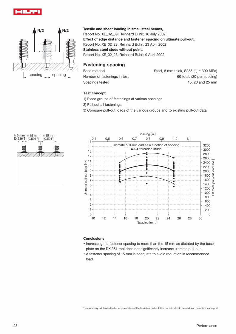
Tensile and shear loading in small steel beams, Report No. XE_02_39; Reinhard Buhri; 16 July 2002Effect of edge distance and fastener spacing on ultimate pull-out, Report No. XE_02_28; Reinhard Buhri; 23 April 2002Stainless steel studs without point, Report No. XE_02_23; Reinhard Buhri; 9 April 2002
Edge distanceBase material Steel, 8 mm thick, S235 (fu = 390MPa)Number of fastenings in test 120 total, (20 per edge distance)Edge distances tested 3, 4, 5, 6, 7, 8 and 25 mm
Test concept1) Place groups of fastenings at various edge distances2) Pull out all fastenings3) Compare ultimate pull-out loads for the various groups to existing ultimate pull-
out data
edge distance
N/2N/2
Conclusions• Increasing the edge distance to more than 6 mm does not result in increased
ultimate pull-out.• An edge distance of 6mm is adequate to avoid reduction in recommended load.
This summary is intended to be representative of the test(s) carried out. It is not intended to be a full and complete test report.
Performance
28 Performance
N/2
spacingspacing
N/2
Conclusions• Increasing the fastener spacing to more than the 15 mm as dictated by the base-
plate on the DX 351 tool does not significantly increase ultimate pull-out.• A fastener spacing of 15 mm is adequate to avoid reduction in recommended
load.
Tensile and shear loading in small steel beams, Report No. XE_02_39; Reinhard Buhri; 16 July 2002Effect of edge distance and fastener spacing on ultimate pull-out, Report No. XE_02_28; Reinhard Buhri; 23 April 2002Stainless steel studs without point, Report No. XE_02_23; Reinhard Buhri; 9 April 2002
Fastening spacingBase material Steel, 8 mm thick, S235 (fu = 390 MPa)Number of fastenings in test 60 total, (20 per spacing)Spacings tested 15, 20 and 25 mm
Test concept1) Place groups of fastenings at various spacings2) Pull out all fastenings3) Compare pull-out loads of the various groups and to existing pull-out data
This summary is intended to be representative of the test(s) carried out. It is not intended to be a full and complete test report.
Performance 29
This summary is intended to be representative of the test(s) carried out. It is not intended to be a full and complete test report.
Performance
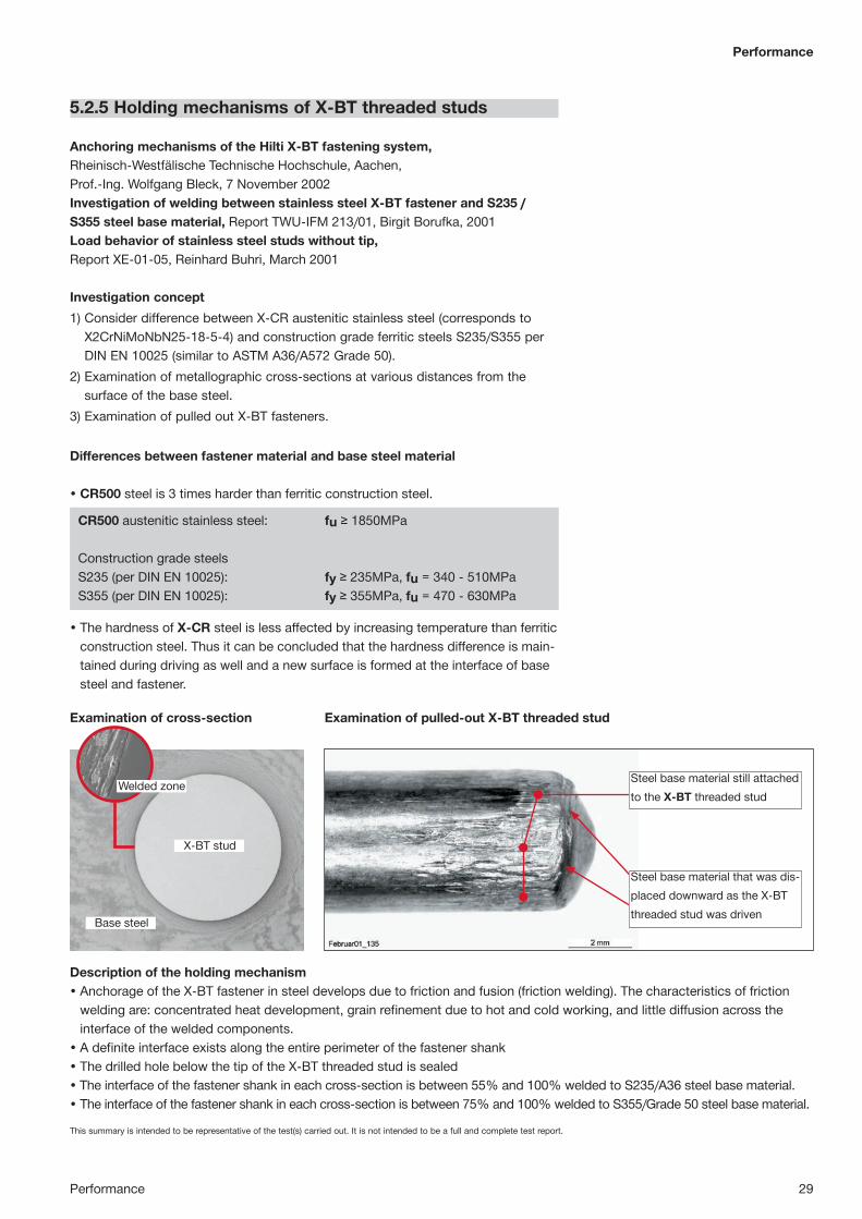
5.2.5 Holding mechanisms of X-BT threaded studs
Anchoring mechanisms of the Hilti X-BT fastening system, Rheinisch-Westfälische Technische Hochschule, Aachen, Prof.-Ing. Wolfgang Bleck, 7 November 2002Investigation of welding between stainless steel X-BT fastener and S235 / S355 steel base material, Report TWU-IFM 213/01, Birgit Borufka, 2001Load behavior of stainless steel studs without tip, Report XE-01-05, Reinhard Buhri, March 2001
Investigation concept1) Consider difference between X-CR austenitic stainless steel (corresponds to
X2CrNiMoNbN25-18-5-4) and construction grade ferritic steels S235/S355 per DIN EN 10025 (similar to ASTM A36/A572 Grade 50).
2) Examination of metallographic cross-sections at various distances from the surface of the base steel.
3) Examination of pulled out X-BT fasteners.
Differences between fastener material and base steel material
• CR500 steel is 3 times harder than ferritic construction steel.
CR500 austenitic stainless steel: fu ≥ 1850MPa
Construction grade steelsS235 (per DIN EN 10025): fy ≥ 235MPa, fu = 340 - 510MPaS355 (per DIN EN 10025): fy ≥ 355MPa, fu = 470 - 630MPa
• The hardness of X-CR steel is less affected by increasing temperature than ferritic construction steel. Thus it can be concluded that the hardness difference is main-tained during driving as well and a new surface is formed at the interface of base steel and fastener.
Welded zone
X-BT stud
Base steel
Steel base material still attached to the X-BT threaded stud
Steel base material that was dis-placed downward as the X-BT threaded stud was driven
Description of the holding mechanism• Anchorage of the X-BT fastener in steel develops due to friction and fusion (friction welding). The characteristics of friction
welding are: concentrated heat development, grain refinement due to hot and cold working, and little diffusion across the interface of the welded components.
• A definite interface exists along the entire perimeter of the fastener shank• The drilled hole below the tip of the X-BT threaded stud is sealed• The interface of the fastener shank in each cross-section is between 55% and 100% welded to S235/A36 steel base material.• The interface of the fastener shank in each cross-section is between 75% and 100% welded to S355/Grade 50 steel base material.
Examination of cross-section Examination of pulled-out X-BT threaded stud

This summary is intended to be representative of the test(s) carried out. It is not intended to be a full and complete test report.
30 Performance
5.3 Corrosion resistance
5.3.1 X-BT threaded stud fastening corrosion data
Blunt-tip stainless steel stud with sealing washer, Report No. XE_02_13; Reinhard Buhri; June 2002
Corrosion data
Base material Steel, 8 mm thick, S235 (fu = 385 MPa) and S355 (fu = 630 MPa)Number of fastenings in test 120 total, (60 per steel grade)Salt spray test 90 days, performed according to DIN 50 021SS / ASTM G 8585)
Test concept
1) Make 60 fastenings in steel of each grade (S235 and S355 steel).2) Perform pullout tests of 30 fastenings from each steel grade before performing
the salt spray test.3) Perform pullout tests of 30 fastenings from each steel grade after the salt spray
test.4) Compare the ultimate pull-out loads before and after the 90 day
salt spray test for each steel grade.5) Examine the area around the fastening points after pulling out the fasteners
Pull-out test results for S355 steel
Summary of results from the pull-out tests• Similar results for S235 steel grade.
-2 0 2 4 6 8 10 12 14 16 18 20 22 24 26 28 30 32 34Ultimate pull-out loads [kN]
-3
-2
-1
0
1
2
3
Theo
retic
al q
uant
ile
0.01
0.05
0.25
0.50
0.75
0.90
0.99
pull-out after 5 years of corrosion field testreference values before test
Acc
umul
ated
freq
uenc
y [%
]
0
500
1000
1500
2000
2500
3000
3500
4000
4500
5000
5500
6000
5000
7000
7500
Ultimate pull-out loads [lbs.]

This summary is intended to be representative of the test(s) carried out. It is not intended to be a full and complete test report.
Performance
Performance 31
Observations and examination
After 90 days of salt spray, the bottom side of the 8 mm [5/16"] steel plate was examined. No evidence of damage or corrosion could be found.
Corrosion resistance of Hilti CR500 stainless steel in comparison with AISI 304 and AISI 316; FMPA Baden-Württemberg; Report No. VI.10.1.7c; July 2000
Prepared X-BT fastenings after driving
Drilled holes after 90 days salt spray test and after pull-out of the X-BT fas-teners. These holes appear clean and no evidence of corrosion is visible.
Sealing washer
Shank made of nitrogen-alloyed austenitic stainless steel CR500
Threaded sleeve and washer of X2CrNiMo17132 / X5CrNiMo17-12-2+2H (conforms to A4 and A316)
Black elastomer sealing washer
Potential-static test carried out with rods and nails in synthetic sea water as per ASTM D 1141
Conclusions from the tests• Ultimate pull-out of the fastenings was not affected by 90 days of salt spray test.• After 90 days salt spray test no corrosion was found in the drilled holes. This is
strong evidence that the sealing washer provides an effective seal.• After 90 days salt spray test, there was no evidence of corrosion on the bottom
side of the steel plate. This shows that drilling the hole and driving the fastener does not cause damage on the bottom side.
• CR 500 is at least as resistant as AISI grade 316.

This summary is intended to be representative of the test(s) carried out. It is not intended to be a full and complete test report.
32 Performance
5.3.2 Contact corrosion – X-BT stainless steel stud in carbon steel
Corrosion behavior of X-CR fasteners, Report No. VI.10.1.7; FMPA Stuttgart; May 1994.Corrosion behavior of stainless steel DX fasteners in carbon steel; G. Felder and M. Siemers, Schaan, September 2005
General commentsTwo materials of different resistance/polarity exposed to the same media, in direct electrical contact, lead to accelerated corrosion of an electrochemically “less noble” material in contact with a “noble” material. The material loss of the noble partner is reduced, the loss of surface area of the less noble partner is increased. Prerequisite for this form of corrosion is an electrically conductive connection between these two materials.
Whether contact corrosion occurs depends also on the surface area ratio.
If the surface of the less “noble” material (1) is greater than that of the more “noble” material (2), it will act as a very small cathode and the current density on the “large anodic” less noble material will be very small. Further, this also implies a very low rate of corrosion of the “less noble” material due to electrochemical effects.
However, if the surface of the less “noble” material (1) is smaller than that of the more “noble” material (2), the rate of corrosion of the “less noble” material will be very high.
Hilti X-BT in carbon steel
Where stainless steels are concerned, contact corrosion is not a matter of concern. Stainless steels are higher in the galvanic series, i.e. more noble than most generally used materials such as aluminium, zinc and steel. Stainless steel in contact with these materials thus gains cathodic protection. Contact therefore generally has a favorable effect on the corrosion properties of stainless steels.
Due to the electrochemical effects as described above, the “noble” stainless steel fastener induces a very low rate of corrosion of the “less noble” base material and fastened material, or possibly no corrosion at all. This behavior has also been confirmed in a number of salt spray tests and in long-term tests with exposure to sea water in the tidal zone on an island in the North Sea. In all of these tests, no corrosion occurred. The condition of a specimen after seven years of sea water tests is shown in the photo on the left. No evidence of corrosion can be found at the anchoring zone of the X-BT fastener. The seal achieved has remained fully functional, no electrolyte is present and contact corrosion is not an issue.
Steel base material after 10 years of exposure to sea water and pull-out of the X-BT fastener. The hole appears clean and no evidence of corrosion is visible.
Material 1 Material 2
Material 1 Material 2

Performance
Performance 33
5.3.3 Corrosion data from field tests at Helgoland Island (North Sea)
Expert assessment: Investigation of the corrosion resistance of Hilti X-BT fasteners in marine atmospheres and in sea water, 9004742000 G/Bf; MPA, University of Stuttgart; Feb 3, 2014
Test materialBase material S235 steel (fu = 439 MPa), 8 mm thickNumber of specimens 24 steel plates, each with 18 X-BT studs
Test procedure
The test specimens were installed in May 2003 and samples taken periodically from each zone for assessment in June 2004, June 2005, May 2008 and April 2013.
Microscopic and metallurgical investigations to assess corrosion were carried out by MPA, University of Stuttgart. The tensile resistance tests were carried out by Hilti under supervision of the MPA.
Test results
Test specimens after 10 years of exposure to sea water in the tidal zone of the North Sea. No evidence of corrosion is visible on the X-BT studs and X-FCM discs. Only slight discoloration due to deposits can be observed on the X-FCM discs.
Conclusions• After 10 years of exposure to sea water, no obvious signs of corrosion were found
on the X-BT fasteners.• After 10 years of exposure to sea water, no relevant signs of corrosion were found
on the X-FCM fasteners.• After 10 years of exposure to sea water, no corrosion was found in the drilled
holes. This is strong evidence that the sealing washer provides an effective seal.• Ultimate pull-out strength of the fasteners was not affected by the field tests. The
pull-out load achieved in monitoring tests carried out in June 2003 was 8.6 kN, and in 2013 it was 10.3 kN.
Based on the long-term tests carried out by the MPA as described above, the University of Stuttgart [Expert Assessment, 9004742000 G/Bf Feb 3, 2014] came to the following conclusion:
Marine atmosphere test rig with X-BT test specimens installed.
See water test rig with test specimens installed (X-BT with and without X-FCM grating discs).
• 8 specimens in an atmospheric test-ing rig in accordance with ISO 8565
• 16 specimens in a sea water testing rig, wave zone and tide zone, in accordance with ISO 11306
From a corrosion-specific point of view, it can thus be assumed that the Hilti X-BT system will have a life of more than 40 years, even under atmo-spheric conditions (corrosion categories C4 respectively C5-M) of use where chloride is present (marine atmospheres and in the splash zone).
Steel base material after 10 years of exposure to sea water and pull-out of the X-BT fastener. The hole appears clean and no evidence of corrosion is visible.

34 Perfomance
Load-deformation behavior of steel with X-BT fasteners Evaluated in tensile tests performed with coupons with X-BT fasteners (XE_02_07)
Conclusions• The very high net section efficiencies observed with Hilti DX powder-actuated
fasteners also develop for plates with X-BT fasteners. • Generally, the presence of an X-BT fastener need not be taken into account in the
design of tensile members made of structural steel. • In case of exceptionally high fastener concentrations (net area < 92 % of gross
area), application of the design provisions of AISC-LRFD or Eurocode 3 for drilled holes leads to conservative results.
5.4 Effect of X-BT threaded stud fastenings on steel basematerial
Experimental investigations on the effect of X-BT fasteners on the static strength of the base material structural steel Report No. XE_02_07; Hermann Beck; 17 June 2002Experimental investigations on the effect of X-BT fasteners on the fatigue strength of the base material structural steel Report No. 2010-57X by Prof. U. Kuhlmann and H.P. Günther from the University of Stuttgart: Fatigue classification of the constructional detail “Structural steel base material wih the Hilti powder-actuated fastener X-BT” in compliance with Eurocode 3 Part 1-9 (EN 1993-1-9), (2010)Reports No. 453´150/1e, 453´150/2e, 453´150/3e, 455´377/e by EMPA, Swiss Federal Laboratories for Materials Testing and Research (2010)Report No. TWU-FSRL-13/09 by Hilti FSRL, Fastening System Research Laboratories (2010).
Base material (static tests): Steel, 8 and 10 mm, S235 and S355Base material (fatigue tests): Steel, 8, 20 and 40 mm, S235, S355, S460M, S460G4+M Number of fastenings in test: 48 static tensile and 191 fatigue tests
This summary is intended to be representative of the test(s) carried out. It is not intended to be a full and complete test report.

Performance 35
Performance
5.4.1 Fatigue classification in compliance with Eurocode 3(EN 1993-1-9). Structural steel base material with Hilti powder-actuated fastener X-BT
Hilti ran a comprehensive fatigue test program in order to classify the constructional detail “Structural steel base material with the Hilti powder-actuated fastener X-BT” in compliance with the Eurocode 3 (EN 1993-1-9, [2]). A corresponding evaluation was made by Prof. U. Kuhlmann and Prof. H.P. Günther from the University ofStuttgart (Report No. 2010-57X [1]).
Category 90 corresponds with a standard category according to Table 7.1 of EN 1993-1-9 [2] with a slope m = 3 for cycles N ≤ 5 million cycles and a slope m = 5 for N > 5 million cycles (see Figure 2). Category 100 (m = 5) - with a constant slope m = 5 for N ≤ 100million cycles - represents a possible, alternate option in compliance with the Eurocode 3. The latter is recommended in case of low amplitude high cycle fatigue loading. When using a fatigue assessment procedure based on a linear damage accumulation a mixture of bothcategories is not allowed. The structural steel grades S235 up to S460 according to EN 10025-2, EN 10025-3, EN 10025-4 and EN 10225 are covered. These grades include thermo mechanically rolled fine grain steels. Recent testing additionally confirmed the same detail category for quenched and tempered structural steel S690Q up to S960Q according to EN 10025-6. Those steel grades are often used in crane construction. (Pre-drilled holes without fasteners are also covered for these grades. Pull-out fasteners are not covered as in most cases the fastener itself fractures before it is pulled out from S690Q to S960Q base material, as the anchorage resistance of the X-BT in such high strength base material is exceptionally high). The following Figure 1 shows a summary of all test data including the fatigue classification in keeping with the Eurocode 3.
Detailcategory
Constructional detail Description Requirements
90
Hilti X-BT powder-actuated fasteners with pre-drilled hole in structural steel base material. Imperfect fastener installations as e.g. pulled-out fasteners or pre-drilled holes without fasten-ers are covered.
Δσ to be calculated by the gross cross-section. Installation, static loading and spacing of fasteners only in accordance with the requirements of the Hilti X-BT threaded fastener specification.Plate thickness t ≥ 8 mmEdge distance ≥ 15 mm
100m = 5
X-BT Specification Suppl. 11/2011
Hilti X-BT Threaded Fastener Specification, Supplement 11/2011 10
2.2 Specifics on fatigue classification 2.2.1 Fatigue classification in compliance with Eurocode 3 (EN 1993-1-9) Hilti ran a comprehensive fatigue test program in order to classify the constructional detail “Structural steel base material with the Hilti powder-actuated fastener X-BT” in compliance with the Eurocode 3 (EN 1993-1-9, [7]). A corresponding evaluation was made by Prof. U. Kuhlmann and H.P. Günther from the University of Stuttgart (Report No. 2010-57X [6]).
Table 7. Recommendation of fatigue detail category according to EN 1993-1-9:2005 [6, 1]
Detail category Constructional detail Description Requirements
90
Hilti X-BT powder-actuated fasteners with pre-drilled hole in structural steel base material. Imperfect fastener installations as e.g. pulled-out fasteners or pre-drilled holes without fasten-ers are covered.
∆σ to be calculated by the gross cross-section. Installation, static loading and spacing of fasteners only in accordance with the require-ments of the Hilti X-BT threaded fastener specifica-tion [1] Plate thickness t 8 mm Edge distance 15 mm
100 m = 5
Category 90 corresponds with a standard category according to Table 7.1 of EN 1993-1-9 [7] with a slope m = 3 for cycles N 5 million cycles and a slope m = 5 for N > 5 million cycles (see Figure 8). Category 100 (m = 5) with a constant slope m = 5 for N 100 million cycles represents a possible, alternate option in compliance with the Eurocode 3. The latter is recommended in case of low amplitude high cycle fatigue load-ing. When using a fatigue assessment procedure based on a linear damage accumulation a mixture of both categories is not allowed.
The structural steel grades S235 up to S460 according to EN 10025-2, EN 10025-3, EN 10025-4 and EN 10225 are covered. These grades include thermo mechanically rolled fine grain steels.
The following Figure 7 shows a summary of all test data including the fatigue classification in keeping with the Eurocode 3.
Fatigue test results Base material with Hilti X-BT fasteners
Cycle Life N
Stre
ss R
ange
[N/m
m²]
EC3-90 EC3-100/m=5 Test results Run-outs
104 5 105 5 106 2 5 10750
75
100
125
150
175
200
225
250275300325350375400425
Fatigue categories according to Eurocode 3 with constant amplitude fatigue limit at 5 million cycles
Figure 7. Test data compared with fatigue recommendation according to Eurocode 3 [6, 1]
Table 1. Recommendation of fatigue detail category according to EN 1993-1-9:2005 [1]
Figure 1. Test data compared with fatigue recommendation according to Eurocode 3 [1]
X-BT Specification Suppl. 11/2011
Hilti X-BT Threaded Fastener Specification, Supplement 11/2011 10
2.2 Specifics on fatigue classification 2.2.1 Fatigue classification in compliance with Eurocode 3 (EN 1993-1-9) Hilti ran a comprehensive fatigue test program in order to classify the constructional detail “Structural steel base material with the Hilti powder-actuated fastener X-BT” in compliance with the Eurocode 3 (EN 1993-1-9, [7]). A corresponding evaluation was made by Prof. U. Kuhlmann and H.P. Günther from the University of Stuttgart (Report No. 2010-57X [6]).
Table 7. Recommendation of fatigue detail category according to EN 1993-1-9:2005 [6, 1]
Detail category Constructional detail Description Requirements
90
Hilti X-BT powder-actuated fasteners with pre-drilled hole in structural steel base material. Imperfect fastener installations as e.g. pulled-out fasteners or pre-drilled holes without fasten-ers are covered.
∆σ to be calculated by the gross cross-section. Installation, static loading and spacing of fasteners only in accordance with the require-ments of the Hilti X-BT threaded fastener specifica-tion [1] Plate thickness t 8 mm Edge distance 15 mm
100 m = 5
Category 90 corresponds with a standard category according to Table 7.1 of EN 1993-1-9 [7] with a slope m = 3 for cycles N 5 million cycles and a slope m = 5 for N > 5 million cycles (see Figure 8). Category 100 (m = 5) with a constant slope m = 5 for N 100 million cycles represents a possible, alternate option in compliance with the Eurocode 3. The latter is recommended in case of low amplitude high cycle fatigue load-ing. When using a fatigue assessment procedure based on a linear damage accumulation a mixture of both categories is not allowed.
The structural steel grades S235 up to S460 according to EN 10025-2, EN 10025-3, EN 10025-4 and EN 10225 are covered. These grades include thermo mechanically rolled fine grain steels.
The following Figure 7 shows a summary of all test data including the fatigue classification in keeping with the Eurocode 3.
Fatigue test results Base material with Hilti X-BT fasteners
Cycle Life N
Stre
ss R
ange
[N/m
m²]
EC3-90 EC3-100/m=5 Test results Run-outs
104 5 105 5 106 2 5 10750
75
100
125
150
175
200
225
250275300325350375400425
Fatigue categories according to Eurocode 3 with constant amplitude fatigue limit at 5 million cycles
Figure 7. Test data compared with fatigue recommendation according to Eurocode 3 [6, 1]
This summary is intended to be representative of the test(s) carried out. It is not intended to be a full and complete test report.

This summary is intended to be representative of the test(s) carried out. It is not intended to be a full and complete test report.
36 Performance
5.4.2 Approved fatigue categories by DNV-GL (Det NorskeVeritas - Germanischer Lloyd), LR (Lloyd's Register) andABS (American Bureau of Shipping)Towers for wind turbines, offshore structures or crane constructions often are approved by classification societies like DNV-GL, LR or ABS. Those classification societies recently also approved the fatigue category for the constructional detail “Structural steel base material with Hilti powder-actuated fastener X-BT”, see Table 2.
Table 2. Approved fatigue detail categoriesNotes on DNV-GL Type Approval:In order to allow clear use of the design category, DNV-GL proposed only to use thestandard category 90 and omit the alternative option 100 with m = 5. DNV-GL also limited the use to the thickness range typically used in steel towers of wind turbines(t ≤ 60 mm) in case of fatigue design according to Eurocode 3 [2]. In case thicker plates are exceptionally used, acceptance is possible based on case specific con-sideration. Differing from the provisions in EN 1993-1-9 [2], the DNV-GL fatigue standard DNV-GL-RP-C203 [3] requires the consideration of the size effect (coeffi-cient k = 0.15) for the detail category independent from the constructional detail. Therefore, for compliant design with DNV-GL-RP-C203 a thickness effect is consid-ered for thickness t ≥ 25 mm.
Notes on ABS Type Approval:The classification according to ABS fatigue standard [4] includes structural steel grades with a nominal yield strength ranging from 235 to 460 N/mm². The classifi-cation according to Eurocode 3 [2] includes additionally also quenched steels S690Q up to S960Q according to EN 10025-6. The fatigue strength curves are mathematically described by the following formula:log N = log ā – m . log Δσ
The parameters m and log ā of the fatigue curves 90 and C2 are summarized in the following tables 3 & 4. Table 5 gives also a comparison of the stress ranges Δσ for selected numbers of cycles and Figure 2 shows a graph with test data and the ap-proved fatigue categories.
Number of load cycles N m log ā
N ≤ 5.106 3 12.1645.106 ≤ N ≤ 108 5 15.807
Number of load cycles N m log ā
N ≤ 107 3 12.301N > 107 5 15.835
Table 3. Parameters of fatigue curve 90 according to EN 1993-1-9
Table 4. Parameters of fatigue curve C2 according to DNV-GL-RP-C203
Classification Society
Hilti Type Approval Certificate Fatigue standard Detail
category Plate thickness Thickness effect
DNV-GL 12272-10HH EC 3, EN 1993-1-9 [2] 90 8 mm ≤ t ≤ 60 mm No.
ks = 1
DNV-GL RP-C203 [3] C2 t ≥ 8 mm for t ≥ 25 mmk = 0.15
LR 03/0070(E3) EC 3, EN 1993-1-9 [2]90
t ≥ 8 mm see EC3100 m = 5
ABS 16-HS 1545448-PDA
ABS Offshore Guide [4]ABS-(A) Class D
t ≥ 8 mm see ABS-Guide
EC 3, EN 1993-1-9 [2]90
t ≥ 8 mm see EC3100 m = 5

This summary is intended to be representative of the test(s) carried out. It is not intended to be a full and complete test report.
Perfomance
Performance 37
Literature:[1] Kuhlmann, U., Günther, H-P. (2010): Fatigue strength of the constructional detail “Structural steel base material with the Hilti
powder-actuated fastener X-BT” in compliance with Eurocode 3 Part 1-9 (EN 1993-1-9), Institut für Konstruktion und Ent-wurf, Stahl- Holz- und Verbundbau, University of Stuttgart, Report Nr. 2010-57X, December 28, 2010
[2] EN 1993-1-9:2005 (2005): Eurocode 3: Design of steel structures – Part 1-9: Fatigue, European Standard, May 2005
[3] DNV-GL-RP-C203 (2016), Recommended Practice: Fatigue design of offshore steel structures, April 2016
[4] ABS (2014): Guide for the fatigue assessment of offshore structures, American Bureau of Shipping, April 2003, updated February 2014
Stress range Δσ [N/mm²]Number of load cycles
N
EC3 - 90 C2
1.105 244.3 271.41.106 113.4 126.02.106 90.0 100.05.106 66.3 73.71.107 57.7 58.51.108 36.4* 36.9
* corresponds to cut-off limit
Table 5. Comparison of stress ranges X-BT Specification Suppl. 11/2011
Hilti X-BT Threaded Fastener Specification, Supplement 11/2011 21
Fatigue classification Base material with Hilti X-BT fasteners
Cycle Life N
Stre
ss R
ange
��
[N/m
m²]
EC3-90 C2 (DNV-GL) Test results Run-outs
104 5 105 5 106 2 5 107 10810
20
30
40
5060708090
100
200
300
400
500600700800900
1000
Figure 8. Test data compared with approved GL and DNV fatigue categories
3 Literature
[1] Hilti Corporation (2010): Hilti X-BT Threaded Fastener Specification, Edition December 2010
[2] Hilti Corporation (2009): Hilti Direct Fastening Technology Manual, Edition 11/2009
[3] Kuhlmann, U., Günther, H-P. (2011): Hilti powder-actuated fastener X-BT in combination with the Hilti fastening tools DX 351 BT/BTG for the use in cast iron base material according to EN 1563, Evalua-tion Report, Institut für Konstruktion und Entwurf, Stahl- Holz- und Verbundbau, University of Stuttgart, Report Nr. 2011-24X, Oct. 11, 2011.
[4] GL, Germanischer Lloyd (2011): Approval Certificate: 12272-10HH, Mechanical Fastening Systems, Hilti X-BT stainless steel threaded fasteners, Hamburg, 2011-11-04
[5] DNV, Det Norske Veritas (2011): Type Approval Certificate No. S-6751, Structural Connecting Ele-ments: X-BT threaded fasteners, Grating fasteners X-FCM-R, X-FCM-M, Høvik, 2011-10-26
[6] Kuhlmann, U., Günther, H-P. (2010): Fatigue strength of the constructional detail “Structural steel base material with the Hilti powder-actuated fastener X-BT” in compliance with Eurocode 3 Part 1-9 (EN 1993-1-9), Institut für Konstruktion und Entwurf, Stahl- Holz- und Verbundbau, University of Stuttgart, Report Nr. 2010-57X, December 28, 2010
[7] EN 1993-1-9:2005 (2005): Eurocode 3: Design of steel structures – Part 1-9: Fatigue, European Standard, May 2005
[8] DNV-RP-C203, Det Norske Veritas (2010): Recommended Practice: Fatigue design of offshore steel structures, April 2010
Figure 2. Test data compared with approved fatigue categories 90 and C2
Stre
ss R
ange
∆Ϭ
[N/m
m2 ]
38 Performance
5.5 Technical data for X-BT fastenings made to cast ironwith spheroidal graphite
5.5.1 Cast iron specification
Components made from cast iron with spheroidal graphite are typically used in the nacelle of wind towers. The preferred grade is EN-GJS-400-18-LT according to EN 1563 with a minimum ultimate strength of 400 N/mm² (for thickness t ≤ 30 mm), a minimum fracture strain A of 18 % and with impact toughness properties suitable for use in cold temperatures. The use of cast iron with spheroidal graphite allows economical production of complex machinery parts combined with ductile material behaviour.
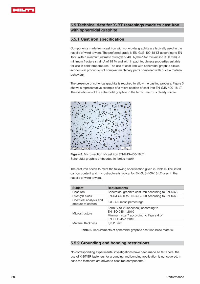
The presence of spherical graphite is required to allow the casting process. Figure 3 shows a representative example of a micro section of cast iron EN-GJS-400-18-LT. The distribution of the spheroidal graphite in the ferritic matrix is clearly visible.
Figure 3. Micro section of cast iron EN-GJS-400-18LT:Spheroidal graphite embedded in ferritic matrix
X-BT Specification Suppl. 11/2011
Hilti X-BT Threaded Fastener Specification, Supplement 11/2011 3
1. Technical data for X-BT fastenings made to cast iron with spheroi-dal graphite
1.1 Cast iron specification
Components made from cast iron with spheroidal graphite are typically used in the nacelle of wind towers. The preferred grade is EN-GJS-400-18-LT according to EN 1563 with a minimum ultimate strength of 400 N/mm² (for thickness t 30 mm), a minimum fracture strain A of 18 % and with impact toughness properties suitable for use in cold temperatures. The use of cast iron with spheroidal graphite allows economical production of complex machinery parts combined with ductile material behaviour.
The presence of spherical graphite is required to allow the casting process. Figure 2 shows a representative example of a micro section of cast iron EN-GJS-400-18-LT. The distribution of the spheroidal graphite in the ferritic matrix is clearly visible.
Figure 2. Micro section of cast iron EN-GJS-400-18LT:
Spheroidal graphite embedded in ferritic matrix
The cast iron needs to meet the following specification given in Table 1. The listed carbon content and micro-structure is typical for EN-GJS-400-18-LT used in the nacelle of wind towers.
Table 1. Requirements of spheroidal graphite cast iron base material
Subject Requirements Cast iron Spheroidal graphite cast iron according to EN 1563 Strength class EN-GJS-400 to EN-GJS-600 according to EN 1563 Chemical analysis and amount of carbon 3.3 - 4.0 mass percentage
Microstructure Form IV to VI (spherical) according to EN ISO 945-1:2010 Minimum size 7 according to Figure 4 of EN ISO 945-1:2010
Material thickness tII 20 mm
Subject RequirementsCast iron Spheroidal graphite cast iron according to EN 1563Strength class EN-GJS-400 to EN-GJS-600 according to EN 1563Chemical analysis andamount of carbon 3.3 - 4.0 mass percentage
Microstructure
Form IV to VI (spherical) according to EN ISO 945-1:2010Minimum size 7 according to Figure 4 of EN ISO 945-1:2010
Material thickness tII ≥ 20 mm
Table 6. Requirements of spheroidal graphite cast iron base material
The cast iron needs to meet the following specification given in Table 6. The listed carbon content and microstructure is typical for EN-GJS-400-18-LT used in the nacelle of wind towers.
5.5.2 Grounding and bonding restrictions
No corresponding experimental investigations have been made so far. There, the use of X-BT-ER fasteners for grounding and bonding application is not covered, in case the fasteners are driven to cast iron components.
Performance 39
Perfomance
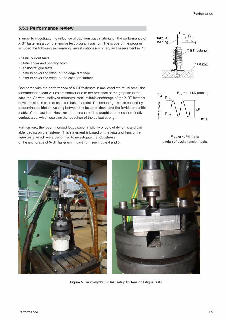
Figure 4. Principle sketch of cyclic tension tests
5.5.3 Performance review
In order to investigate the influence of cast iron base material on the performance of X-BT fasteners a comprehensive test program was run. The scope of the program included the following experimental investigations (summary and assessment in [1]):
• Static pullout tests• Static shear and bending tests• Tension fatigue tests• Tests to cover the effect of the edge distance• Tests to cover the effect of the cast iron surface
Compared with the performance of X-BT fasteners in unalloyed structural steel, the recommended load values are smaller due to the presence of the graphite in the cast iron. As with unalloyed structural steel, reliable anchorage of the X-BT fastener develops also in case of cast iron base material. The anchorage is also caused by predominantly friction welding between the fastener shank and the ferritic or perlitic matrix of the cast iron. However, the presence of the graphite reduces the effective contact area, which explains the reduction of the pullout strength.
Furthermore, the recommended loads cover implicitly effects of dynamic and vari-able loading on the fastener. This statement is based on the results of tension fa-tigue tests, which were performed to investigate the robustnessof the anchorage of X-BT fasteners in cast iron, see Figure 4 and 5.
X-BT Specification Suppl. 11/2011
Hilti X-BT Threaded Fastener Specification, Supplement 11/2011 7
1.6 Performance review In order to investigate the influence of cast iron base material on the performance of X-BT fasteners a com-prehensive test program was run. The scope of the program included the following experimental investigations (summary and assessment in [3]):
Static pullout tests Static shear and bending tests Tension fatigue tests
Tests to cover the effect of the edge distance Tests to cover the effect of the cast iron surface
Compared with the performance of X-BT fasteners in unalloyed structural steel (see Figure 1, [1] and [2]), the recommended load values are smaller due to the presence of the graphite in the cast iron. As with unalloyed structural steel, reliable anchorage of the X-BT fastener develops also in case of cast iron base material. The anchorage is also caused by predominantly friction welding between the fastener shank and the ferritic or perlitic matrix of the cast iron. However, the presence of the graphite reduces the effective contact area, which explains the reduction of the pullout strength.
Furthermore, the recommended loads cover implicitly effects of dynamic and variable loading on the fastener. This statement is based on the results of tension fatigue tests, which were performed to investigate the ro-bustness of the anchorage of X-BT fasteners in cast iron, see Figure 4 and 5.
F
t
cast iron
X-BT fastener
fatigue loading
tens
ion
F
t
Fmax
Fmin
F
Fmin = 0.1 kN (const.)
Figure 4. Principle sketch of cyclic tension tests
Figure 5. Servo-hydraulic test setup for tension fatigue tests
Fmin = 0.1 kN (const.)
Figure 5. Servo-hydraulic test setup for tension fatigue tests
X-BT Specification Suppl. 11/2011
Hilti X-BT Threaded Fastener Specification, Supplement 11/2011 7
1.6 Performance review In order to investigate the influence of cast iron base material on the performance of X-BT fasteners a com-prehensive test program was run. The scope of the program included the following experimental investigations (summary and assessment in [3]):
Static pullout tests Static shear and bending tests Tension fatigue tests
Tests to cover the effect of the edge distance Tests to cover the effect of the cast iron surface
Compared with the performance of X-BT fasteners in unalloyed structural steel (see Figure 1, [1] and [2]), the recommended load values are smaller due to the presence of the graphite in the cast iron. As with unalloyed structural steel, reliable anchorage of the X-BT fastener develops also in case of cast iron base material. The anchorage is also caused by predominantly friction welding between the fastener shank and the ferritic or perlitic matrix of the cast iron. However, the presence of the graphite reduces the effective contact area, which explains the reduction of the pullout strength.
Furthermore, the recommended loads cover implicitly effects of dynamic and variable loading on the fastener. This statement is based on the results of tension fatigue tests, which were performed to investigate the ro-bustness of the anchorage of X-BT fasteners in cast iron, see Figure 4 and 5.
F
t
cast iron
X-BT fastener
fatigue loading
tens
ion
F
t
Fmax
Fmin
F
Fmin = 0.1 kN (const.)
Figure 4. Principle sketch of cyclic tension tests
Figure 5. Servo-hydraulic test setup for tension fatigue tests

This summary is intended to be representative of the test(s) carried out. It is not intended to be a full and complete test report.
40 Performance
Conclusions from the cyclic tension tests:• The anchorage of the X-BT does not work loose. In none of the tests pull-out of
the fastener from the cast iron was the controlling mode of failure.• Failure was controlled by fatigue fracture of the stainless stud material. The frac-
tures occurred at upper loads significantly beyond the recommended tension load of 0.5 kN.
• For final verification and with respect to the reported design life of wind towers, two fatigue tests were performed with an upper load of 1.0 kN (which is double the recommended tension load) and a target number of 200 million load cycles.
• Both long run samples passed the test without any damage, neither to the fasten-er material nor to the anchorage. Residual static pullout tests of these two sam-ples resulted in a pullout strength beyond 5 kN.
• The test results clearly verify reliable X-BT fastenings to cast iron EN-GJS-400-18LT used in the nacelle of wind towers.
Figure 6. shows a graph of the fatigue test results performed with X-BT fasteners. The load-level of the runouts is by far beyond the recommended working load of 0.5 kN, especially see the two run-outs at 200 million load cycles with an upper load of 1.0 kN.
Figure 6. Results of cyclic tension tests
X-BT Specification Suppl. 11/2011
Hilti X-BT Threaded Fastener Specification, Supplement 11/2011 8
Conclusions from the cyclic tension tests: The anchorage of the X-BT does not work loose. In none of the tests pull-out of the fastener from the cast
iron was the controlling mode of failure. Failure was controlled by fatigue fracture of the stainless stud material. The fractures occurred at upper
loads significantly beyond the recommended tension load of 0.5 kN. For final verification and with respect to the reported design life of wind towers, two fatigue tests were
performed with an upper load of 1.0 kN (which is double the recommended tension load) and a target number of 200 million load cycles.
Both long run samples passed the test without any damage, neither to the fastener material nor to the anchorage. Residual static pullout tests of these two samples resulted in a pullout strength beyond 5 kN.
The test results clearly verify reliable X-BT fastenings to cast iron EN-GJS-400-18LT used in the nacelle of wind towers.
Figure 6 shows a graph of the fatigue test results performed with X-BT fasteners. The load-level of the run-outs is by far beyond the recommended working load of 0.5 kN, especially see the two run-outs at 200 million load cycles with an upper load of 1.0 kN.
104 105 106 107 2.108
Number of cycles N
Upper load Fmax [kN]
0.5
1
2
3
456
Test with failuresTests without failure (run-outs) mean regression curve characteristic fatigue strength
Recommended working load: 0.5 kN
Fasteners: X-BT M8-15-6 SN12-R or X-BT M10-24-6 SN12-RBase material: EN-GJS-400-18-LT
Figure 6. Results of cyclic tension tests
It is further planned to add the use of X-BT fasteners on cast iron components into the X-BT Type Approvals issued by GL [4] and DNV [5].
Literature:[1] Kuhlmann, U., Günther, H-P. (2011): Hilti powder-actuated fastener X-BT in
combination with the Hilti fastening tools DX 351 BT/BTG for the use in cast iron base material according to EN 1563, Evaluation Report, Institut für Konstruktion und Entwurf, Stahl- Holz- und Verbundbau, University of Stuttgart, Report Nr. 2011-24X, Oct. 11, 2011.

This summary is intended to be representative of the test(s) carried out. It is not intended to be a full and complete test report.
Performance 41
Perfomance
5.6 Vibration effects on X-BT threaded stud fastenings
Experimental investigations on the effect of base metal vibrations on the ultimate pull-out Report No. XE_02_09; Hermann Beck; 19 June 2002
Base material Steel, S235Beam section HE-A section, 9 mm flange, 6 mm webTest procedure: Beam loaded in the center Fmax = 155 kN, Fmin = 33 kN Frequency = 6 Hz Number of cycles = 2 MillionNumber of fastenings: 210 X-BT fasteners, some with X-FCM-R grating disks
Conclusions• Cyclic loading applied to steel beams, which causes vibration on the fastener, has
only a negligible effect on the ultimate pull-out of X-BT threaded studs• Cyclic loading applied to steel beams, which causes vibration on the fastener,
does not result in loosening of grating X-FCM-R grating disks
➊ Compression flange➋ Tension flange
➋
➊
➌ Markings to measure disc rotation
➌
Ultimate pull-out of X-BT fasteners before and after cyclic loading of the steel beam
X-BT fasteners in area without grating
X-BT fasteners in area with grating
7.33 kN = Ultimate pull-out on the sam-ple before stress was applied (control). No measurements taken on the com-pression flange in the high stress area due to position of the press.
7.33 kN = Ultimate pull-out on the sam-ple before stress was applied (control).
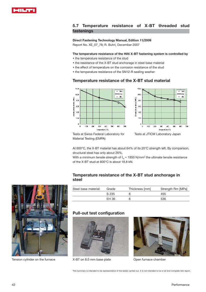
This summary is intended to be representative of the test(s) carried out. It is not intended to be a full and complete test report.
42 Performance
5.7 Temperature resistance of X-BT threaded stud fastenings
Direct Fastening Technology Manual, Edition 11/2009 Report No. XE_07_78; R. Buhri, December 2007
The temperature resistance of the Hilti X-BT fastening system is controlled by • the temperature resistance of the stud• the resistance of the X-BT stud anchorage in steel base material• the effect of temperature on the corrosion resistance of the stud • the temperature resistance of the SN12-R sealing washer
Temperature resistance of the X-BT stud material
At 600°C, the X-BT material has about 64% of its 20°C strength left. By comparison, structural steel has only about 26%. With a minimum tensile strength of fu = 1850 N/mm2 the ultimate tensile resistance of the X-BT stud at 600°C is about 18.8 kN.
Temperature resistance of the X-BT stud anchorage in steel
Steel base material: Grade Thickness [mm] Strength Rm [MPa] S 235 8 455 EH 36 8 536
Pull-out test configuration
Tests at Swiss Federal Laboratory for Material Testing (EMPA)
Tests at JTICM Laboratory Japan
X-BT on 8.0 mm base plate Open furnace chamber Tension cylinder on the furnace

This summary is intended to be representative of the test(s) carried out. It is not intended to be a full and complete test report.
Performance 43
Perfomance
At 600°C, the pull-out resistance of the X-BT has about 71% of its 20°C strength left in steel S235 and about 85% in steel EH36.
At low temperature the pull-out resistance is increasing compared to that at room temperature.
Conclusions• The strength of the X-BT stud and its anchorage in steel base material does not
control the limits of the system under extreme ambient temperatures.• The corrosion resistance of the X-BT stud is verified up to +300°C• The sealing function of the SN12-R sealing washer is verified for a temperature
range of -40°C to +100°C
Pull-
out l
oad
[kN
]
Temperature [°C]
Pull-
out l
oad
NR
k [k
N]
S235 EH36

This summary is intended to be representative of the test(s) carried out. It is not intended to be a full and complete test report.
44 Performance
X-BT-ER M10/3 SN 4X-BT-ER W10/3 SN 4
X-BT-ER M8/7 SN 4 X-BT-ER M6/7 SN 4X-BT-ER W6/7 SN 4
Ø 1
2
[ 0
.472
"]
Ø 4
.5
[ 0
.177
"]
24 [0.945"] 4[0.158"]
4[0.158"]
2 [0.079"]
31.3 [1.232"]
3
4
65 51 27
M8
Ø 1
2[ 0
.472
"]
M10
/W
10
Ø 4
.5
[ 0
.177
"]
24 [0.945"] 5[0.197"]
5[0.197"]
2.4 [0.094"]
31.3 [1.232"]
1 2 3
4
65 5
Ø 1
2
[ 0
.472
"]
M6/
W6
Ø 4
.5
[ 0
.177
"]
20 [0.787"] 5[0.197"]
5[0.197"]
1.6[0.062"]
31.3 [1.232"]
3
4
65 571
5.8 X-BT-ER stainless steel threaded studs electrical performances
Fasteners
Test Report No. 09-IK-0208: Suitability of Hilti X-BT-ER threaded studs as connection point in protective grounding and earthing circuits and for lighting protection; Electro-suisse; May 2015 Test Report No. 09-IK-0208.32V2_e; Electrosuisse, Fehraltorf, Switzerland; May 2010Amtec report 3028883: Finite Element Analysis: X-BT-ER stainless steel threaded stud for electrical connections,Lauffen, Germany, Nov 18, 2015Report No. XE-15-105, “Simulation results: fastening process of XT-BT threaded stud with blunt tip”,Simon Stahel, Schaan, Liechtenstein, October 2015Test Report No. CF-791; Dehn und Söhne GmbH, Neumarkt, Germany; March 2006Test Report No. 70064671; TÜV Test Centre, Frankfurt, Germany; March 2004
5.8.2 Effect of X-BT-ER fasteners on integrity of pipe flange
Installation of a Hilti X-BT(-ER) threaded stud is not expected to have negative influ-ence on the integrity of flanged pipe joints made from typical ductile steel materials, when installed in the outer area of the pipe flange between 2 tension bolts.
Hilti’s recommendations for edge distance, spacing, minimum flange diameter and minimum base material thickness, as well as Hilti’s printed literature, must be con-sidered during design and installation.
• Outer diameter of pipe flange is greater than or equal to 150mm (6 inches)• Minimum edge distance = 6mm, i.e. minimum pipe flange thickness = 12mm• X-BT-ER installed on center of pipe flange and between 2 tension bolts
5.8.1 Contact resistance
Resistance of Stud in cold condition, according to IEC 60947-7-2 < 5 mΩ
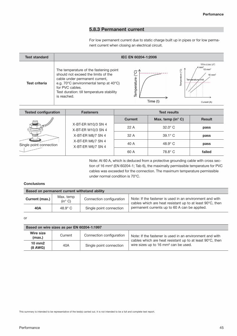
This summary is intended to be representative of the test(s) carried out. It is not intended to be a full and complete test report.
Performance 45
Perfomance
5.8.3 Permanent current
For low permanent current due to static charge built up in pipes or for low perma-nent current when closing an electrical circuit.
Test standard IEC EN 60204-1:2006
Test criteria
The temperature of the fastening point should not exceed the limits of the cable under permanent current, e.g. 70°C (environmental temp at 40°C) for PVC cables. Test duration: till temperature stability is reached.
5.8 X-BT-ER stainless steel threaded studs electrical performances
5.8.1 Permanent current
X-BT-ER M10/3 SN 4 X-BT-ER W10/3 SN 4
X-BT-ER M8/7 SN 4 X-BT-ER M6/7 SN 4 X-BT-ER W6/7 SN 4
Fasteners
Test standard IEC EN 60204-1:2006, Table 6 and D.5
Test criteria
The temperature of the fastening point should not exceed the limits of the cable under permanent current, e.g. 70°C (environmental temp at 40°C), for PVC cables. Test duration: Till temperature stability is reached.
Tested Configuration Tested Fasteners Test Results
Single point connection
X-BT-ER M10/3 SN 4 X-BT-ER W10/3 SN 4 X-BT-ER M8/7 SN 4 X-BT-ER M6/7 SN 4 X-BT-ER W6/7 SN 4
Current Max. temp (in° C) Result
22 A 32.0° C PASS
32 A 39.1° C PASS
40 A 48.9° C PASS
60 A 78.8° C FAILED
Note: At 60 A, which is deduced from a protective grounding cable with cross section of 16 mm² (EN 60204-1; Tab 6), the maximally permissible temperature for PVC cables was exceeded for the connection. The maximum temperature permissible under normal condition is 70°C.
For low permanent current due to static charge built up in pipes or for low permanent current when closing an electrical circuit
Conclusion
Based on wire sizes as per EN 60204-1:1997
Wire size (Max.) Current Connection configuration Note: If the fastener is used in an environment and with cables which are heat resistant up to at least 90°C, then wire sizes up to 16 mm² can be used.
10 mm2 (8 AWG) 40A Single point connection
Based on permanent current withstand ability
Current (Max.) Max. temp (in° C) Connection configuration Note: If the fastener is used in an environment and with cables which are heat resistant up to at least 90°C, then permanent currents up to 60 A can be applied. 40A 48.9° C Single point connection
or
Test Report No. 09-IK-0208.32V2_e; Electrosuisse, Fehraltorf, Switzerland; May 2010 Test Report No. CF-791; Dehn und Söhne GmbH, Neumarkt, Germany; March 2006 Test Report No. 70064671; TÜV Test Centre, Frankfurt, Germany; March 2004 Test Report No. 09-IK-0208: Suitability of Hilti X-BT-ER threaded studs as connection point in protective grounding and earthing circuits and for lighting protection; Electro-suisse, 2015
Tested configuration Fasteners Test results
X-BT-ER M10/3 SN 4X-BT-ER W10/3 SN 4X-BT-ER M8/7 SN 4X-BT-ER M6/7 SN 4X-BT-ER W6/7 SN 4
Current Max. temp (in° C) Result
22 A 32.0° C pass
32 A 39.1° C pass
40 A 48.9° C pass
60 A 78.8° C failed
Note: At 60 A, which is deduced from a protective grounding cable with cross sec-tion of 16 mm² (EN 60204-1; Tab 6), the maximally permissible temperature for PVC cables was exceeded for the connection. The maximum temperature permissible under normal condition is 70°C.
Single point connection
Conclusions
or
Based on permanent current withstand ability
Current (max.) Max. temp (in° C) Connection configuration Note: If the fastener is used in an environment and with
cables which are heat resistant up to at least 90°C, then permanent currents up to 60 A can be applied.40A 48.9° C Single point connection
Based on wire sizes as per EN 60204-1:1997Wire size
(max.) Current Connection configuration Note: If the fastener is used in an environment and with cables which are heat resistant up to at least 90°C, then wire sizes up to 16 mm² can be used.10 mm2
(8 AWG) 40A Single point connection

This summary is intended to be representative of the test(s) carried out. It is not intended to be a full and complete test report. For complete test details, please contact Hilti.
46 Performance
X-BT-ER M8/7 SN 4X-BT-ER M6/7 SN 4X-BT-ER W6/7 SN 4
Current Exposure time Result
2240 A (IEC) 1 s pass
Note: Higher currents for an exposure time of 1 s will result in failed connectionDouble point connection
5.8.4 Short circuit current
For discharging short circuit current while protecting electrical equipment or earth / ground or bonded cable trays and ladders
Tested configuration Fasteners Test results
X-BT-ER M10/3 SN 4X-BT-ER W10/3 SN 4X-BT-ER M8/7 SN 4X-BT-ER M6/7 SN 4X-BT-ER W6/7 SN 4
Current Exposure time Result
1400 A (IEC) 1 s pass
750 A (UL) 4 s pass
Note: Higher currents for a longer exposure time will result in failed connection.Single point connection
Test standards Requirements or test criteria
IEC 61000-5-2
• Tight contact between bonding strap terminal and equipment frame due to low electrical impedance
• Durably resistant to vibration• Durably resistant to corrosion• Durably resistant to mechanical forces and pull out forces
pass
IEC EN 60947-7-2
A grounding connection must be capable of withstanding a high test current (Itest) for an exposure time of 1 second.
Itest = Acable [mm2] x 120 [A/mm2]where Acable = cross sectional area of the attached cable, exposure time 1 second
i.e for wire size 10 mm2, a current of 1200 A for 1 sec
UL 467
• The grounding connection must be capable of withstanding a high test current (Itest) for a specified exposure time.
Table 14.1, e.g.• 14 AWG(2.1mm2) 300A for 4s• 12 AWG(3.3mm2) 470A for 4s• 10 AWG(5.3mm2) 750A for 4s• 8 AWG(8.4mm2) 1180A for 4s
5.8.2 Short circuit current
For discharging short circuit current while protecting electrical equipment or earth / ground or bonded cable trays and ladders
Test Standards Requirements or test criteria
IEC 61000-5-2
• Tight contact between bonding strap terminal and equipment frame due to low electrical impedance
• Durably resistant to vibration • Durably resistant to corrosion • Durably resistant to mechanical forces and pull out forces • Short time current withstand ability in accordance to IEC EN 60947-7-2
Pass
IEC EN 60947-7-2
A grounding connection must be capable of withstanding a high test current (Itest) for an exposure time of 1 second. Itest = Acable [mm2] x 120 [A/mm2] where Acable = cross sectional area of the attached cable, exposure time 1 second i.e for wire size 10 mm2, a current of 1200 A for 1 sec
UL 467
A grounding connection must be capable of withstanding a high test current (Itest) for a specified exposure time. Table 14.1, e.g. • 14 AWG(2.1mm2) 300A for 4s • 12 AWG(3.3mm2) 470A for 4s • 10 AWG(5.3mm2) 750A for 4s • 8 AWG(8.4mm2) 1180A for 4s
Tested Configuration Tested Fasteners Test Results
Single point connection
X-BT-ER M10/3 SN 4 X-BT-ER W10/3 SN 4 X-BT-ER M8/7 SN 4 X-BT-ER M6/7 SN 4 X-BT-ER W6/7 SN 4
Current Exposure time Result
1400 A (IEC) 1 s PASS
750 A (UL) 4 s RATED
Note: Higher currents for a longer exposure time will result in failed connection.
Double point connection
X-BT-ER M8/7 SN 4 X-BT-ER M6/7 SN 4 X-BT-ER W6/7 SN 4
2240 A (IEC) 1 s PASS
Note: Higher currents for an exposure time of 1 s will result in failed connection
Conclusion
Based on wire sizes as per IEC 60947-7-2 & UL 467 (irrespective of current withstand ability)
Wire size (Max.) Fastener Connection configuration
10 mm2 (IEC) 10 AWG (UL)
X-BT-ER M10/3 SN 4 X-BT-ER W10/3 SN 4 X-BT-ER M8/7 SN 4 X-BT-ER M6/7 SN 4 X-BT-ER W6/7 SN 4
Single point connection
16 mm2 (IEC X-BT-ER M8/7 SN 4 X-BT-ER M6/7 SN 4 X-BT-ER W6/7 SN 4
Double point connection
Based on short term current withstand ability (irrespective of wire size)
Current (Max.) Fastener Exposure
time Connection
configuration
1400 A X-BT-ER M10/3 SN 4 X-BT-ER W10/3 SN 4 X-BT-ER M8/7 SN 4 X-BT-ER M6/7 SN 4 X-BT-ER W6/7 SN 4
1 s Single point connection
750 A 4 s
2240 A X-BT-ER M8/7 SN 4 X-BT-ER M6/7 SN 4 X-BT-ER W6/7 SN 4
1 s Double point connection
or
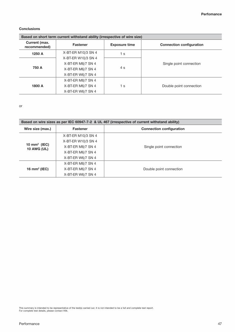
This summary is intended to be representative of the test(s) carried out. It is not intended to be a full and complete test report. For complete test details, please contact Hilti.
Performance 47
Perfomance
Conclusions
or
Based on short term current withstand ability (irrespective of wire size)Current (max.
recommended) Fastener Exposure time Connection configuration
1250 A X-BT-ER M10/3 SN 4X-BT-ER W10/3 SN 4X-BT-ER M8/7 SN 4X-BT-ER M6/7 SN 4X-BT-ER W6/7 SN 4
1 s
Single point connection750 A 4 s
1800 AX-BT-ER M8/7 SN 4X-BT-ER M6/7 SN 4X-BT-ER W6/7 SN 4
1 s Double point connection
Based on wire sizes as per IEC 60947-7-2 & UL 467 (irrespective of current withstand ability)
Wire size (max.) Fastener Connection configuration
10 mm2 (IEC)10 AWG (UL)
X-BT-ER M10/3 SN 4X-BT-ER W10/3 SN 4X-BT-ER M8/7 SN 4X-BT-ER M6/7 SN 4X-BT-ER W6/7 SN 4
Single point connection
16 mm2 (IEC)X-BT-ER M8/7 SN 4X-BT-ER M6/7 SN 4X-BT-ER W6/7 SN 4
Double point connection
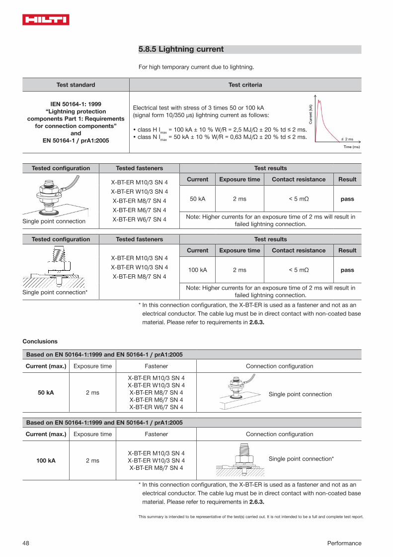
This summary is intended to be representative of the test(s) carried out. It is not intended to be a full and complete test report.
48 Performance
5.8.5 Lightning current
For high temporary current due to lightning.
Test standard Test criteria
IEN 50164-1: 1999“Lightning protection
components Part 1: Requirements for connection components”
and EN 50164-1 / prA1:2005
Electrical test with stress of 3 times 50 or 100 kA (signal form 10/350 μs) lightning current as follows:
• class H Imax = 100 kA ± 10 % W/R = 2,5 MJ/Ω ± 20 % td ≤ 2 ms.• class N Imax = 50 kA ± 10 % W/R = 0,63 MJ/Ω ± 20 % td ≤ 2 ms.
5.8.3 Lightning current
For high temporary current due to lightning.
Test standard
EN 50164-1:1999 “Lightning protection components Part 1: Requirements for connection components” and EN 50164-1 / prA1:2005
Test criteria
Electrical test with stress of 3 times 50 or 100 kA (signal form 10/350 μs) lightning current as follows: • class H Imax = 100 kA ± 10 % W/R = 2,5 MJ/Ω ± 20 % td ≤ 2 ms.
• class N Imax = 50 kA ± 10 % W/R = 0,63 MJ/Ω ± 20 % td ≤ 2 ms.
Tested Configuration Tested Fasteners Test Results
Single point connection
X-BT-ER M10/3 SN 4 X-BT-ER W10/3 SN 4 X-BT-ER M8/7 SN 4 X-BT-ER M6/7 SN 4 X-BT-ER W6/7 SN 4
Current Exposure time Contact resistance Result
50 kA 2 ms < 2,5 mΩ PASS
Note: Higher currents for an exposure time of 2 ms will result in failed lightning connection.
In this connection configuration, the X-BT-ER is used as a fastener and not as an electrical conductor. The cable lug must be in direct contact with non-coated base material. Please refer to requirements in 2.6.3.
Single point connection
X-BT-ER M10/3 SN 4 X-BT-ER W10/3 SN 4 X-BT-ER M8/7 SN 4
100 kA 2 ms < 2,5 mΩ PASS
Note: Higher currents for an exposure time of 2 ms will result in failed lightning connection
Based on EN 50164-1:1999 and EN 50164-1 / prA1:2005
Current (Max.) Exposure time Fastener Connection configuration
50 kA 2 ms
X-BT-ER M10/3 SN 4 X-BT-ER W10/3 SN 4 X-BT-ER M8/7 SN 4 X-BT-ER M6/7 SN 4 X-BT-ER W6/7 SN 4
Single point connection
In this connection configuration, the X-BT-ER is used as a fastener and not as an electrical conductor. The cable lug must be in direct contact with non-coated base material. Please refer to requirements in 2.6.3.
100 kA 2 ms X-BT-ER M10/3 SN 4 X-BT-ER W10/3 SN 4 X-BT-ER M8/7 SN 4
Single point connection
Conclusion
Tested configuration Tested fasteners Test results
X-BT-ER M10/3 SN 4X-BT-ER W10/3 SN 4X-BT-ER M8/7 SN 4X-BT-ER M6/7 SN 4X-BT-ER W6/7 SN 4
Current Exposure time Contact resistance Result
50 kA 2 ms < 5 mΩ pass
Note: Higher currents for an exposure time of 2 ms will result in failed lightning connection.Single point connection
Tested configuration Tested fasteners Test results
X-BT-ER M10/3 SN 4X-BT-ER W10/3 SN 4X-BT-ER M8/7 SN 4
Current Exposure time Contact resistance Result
100 kA 2 ms < 5 mΩ pass
Note: Higher currents for an exposure time of 2 ms will result in failed lightning connection.Single point connection*
* In this connection configuration, the X-BT-ER is used as a fastener and not as an electrical conductor. The cable lug must be in direct contact with non-coated base material. Please refer to requirements in 2.6.3.
* In this connection configuration, the X-BT-ER is used as a fastener and not as an electrical conductor. The cable lug must be in direct contact with non-coated base material. Please refer to requirements in 2.6.3.
Based on EN 50164-1:1999 and EN 50164-1 / prA1:2005
Current (max.) Exposure time Fastener Connection configuration
50 kA 2 ms
X-BT-ER M10/3 SN 4X-BT-ER W10/3 SN 4X-BT-ER M8/7 SN 4X-BT-ER M6/7 SN 4X-BT-ER W6/7 SN 4
Conclusions
Single point connection
Based on EN 50164-1:1999 and EN 50164-1 / prA1:2005
Current (max.) Exposure time Fastener Connection configuration
100 kA 2 msX-BT-ER M10/3 SN 4X-BT-ER W10/3 SN 4X-BT-ER M8/7 SN 4
Single point connection*
This summary is intended to be representative of the test(s) carried out. It is not intended to be a full and complete test report.
Performance 49
Perfomance
5.9 X-BT in stainless steel base material
Hilti internal report XE_07_26; Reinhard Buhri, 21.05.2007
Stainless steel is very hard, so the drilling technique differs from that used for structural steel, the material for which the X-BT system has been optimized. Driving the X-BT stud in stainless steel presents no problem, but drilling is decisive.
Test material and conditions
Type of drill bit: Standard TX-BT 4/7 step shank drill bit Two special shank drill bits for stainless steelType of stainless steel material: Material number:
1.4401, 1.4462, 1.4529, 1.4539 Drilling procedure: Wet or dry Number of tests: 495 drilling operations with 28 drill bitsCondition: Hand held operation, same as the standard operation
Results • With all of the stainless steel materials tested, the standard TX-BT 4/7 drill bit
was found to perform better than special drill bits. • Cooling the drill bit does not lead to better results. • Use of a corded electric drill is recommended due to the longer drilling time. • Best results are achieved with a corded drill set to a speed of 1,000 r.p.m.• To achieve satisfactory drilling performance, much higher pressure must be
applied to the drill bit. • About 25 to 35 holes can be drilled with a TX-BT 4/7 drill bit. • Characteristic pull-out loads are in the 8 to 16 kN range, which provides an
adequate safety factor for the recommended loads.
Recommendation For making fastenings in stainless steel with Hilti X-BT studs, we recommend use of the standard TX-BT 4/7 drill bit with a drill tool having a speed close to 1,000 r.p.m.The following Hilti models are suitable:• UD 30 – set at gear 1 @ 1200 r.p.m• UH 700 – set at gear 1 @ 900 r.p.m• SF 22-A – set at gear 2 @ 1250 r.p.m (cordless tool)

This summary is intended to be representative of the test(s) carried out. It is not intended to be a full and complete test report.
50 Performance
5.10 X-BT under shock loading
Shock tests with X-BT studs and MQ channel systems for fastening electrical cable and pipe runs are described in these documents: Test certificate number QUINETIQ/CMS/TC040089; QinetiQ Shock Test Laboratory, 15.01.2004Report 2004-CMC-R017, TNO Delft, Netherlands, 29.05.2005
Mechanical and electrical equipment fastened with MQ channels and X-BT studs tested under shock load.
• Small-bore pipe runs• High-voltage cable runs• T-bars for fastening high-voltage cables• Cable basket electrical runs• Cable tray electrical runs
All applications were tested with an effective acceleration of 1844 m/s2 in the three orthogonal axes, in horizontal (longitudinal and side to side) and vertical direction. In another test, X-BT studs with a mass of 3 kg each were installed on a shock test rig and tested with a maximum effective acceleration of 4905m/s2.
Test results • The channel system, the X-BT studs and the attached equipment remained
captive at all times. • The tested effective acceleration of 1844 m/s2 corresponds to a shock load
of 188 g.• The X-BT with a fastened mass of 3 kg withstood a shock load of 200 G in
horizontal (shear) and 500 G in longitudinal (tension) direction.
Lightweight high impact shock testing of Hilti X-BT studs for electrical cable holder, electrical box and slotted channel installations are also described in HI-TEST LABORATORIES, INC., Report No. 1475, April 30, 2007. X-BT stud fastened assemblies were subjected to lightweight high impact shock tests in accordance with MIL-S-901D(NAVY) and HI-TEST Procedure No. HT-1780-TP-1, Revision “-”.
Testing was conducted at HI-TEST LABORATORIES, INC., Arvonia, Virginia, using their standard Navy shock testing machine for lightweight equipment. HI-TEST LABORATORIES, INC. is approved for class H.I. (High Impact) shock testing by NAVSEA per NAVSEAINST 9491.1C dated 21 March 1996. Nine blows were applied to each test item - three blows in each of the three mutually perpen-dicular axes of the test item (from the top, back, and side) at hammer heights of 1, 3, and 5 feet. Two separate lightweight shock tests were performed, one for each test panel. Shock test accelerations ranged from - 80 to 300 G's. Test ResultsThere was no evidence of broken or loose parts during the test series. There was also no evidence of damage to the test cables that could be considered an electrical hazard.
Test configuration: Two base plates were populated with MQ channel fastened with X-BT studs. The base plates were rigidly attached to the 2-tonne shock loading machine.

This summary is intended to be representative of the test(s) carried out. It is not intended to be a full and complete test report.
Performance 51
Perfomance
5.11 X-BT stud in steel with a thickness of less than 8 mm
5.11.1 Pull-out capacity in thin steel
Load behavior on special steel structures, Report XE_01_57; R. Buhri; 30. 11. 2001Pull-out strength of blunt-tip stainless steel threaded studs, Report XE_02_23; R. Buhri; 9.4.2002
The characteristic pull-out resistance of X-BT threaded studs is a bi-linear function of base steel thickness as shown in section 5.2.2. A linear function can be derived from this graph for calculation of the reduction factor for the resistance of X-BT fastenings on steel with a thickness of less than 8 mm.
Reduction factor: tll – 2
6α = ; with tll : = thickness of base steel
4 mm ≤ tll ≤ 8 mm
Example For a base steel thickness of 6 mm, the recommended loads using Hilti global safety factors are:
Steel S235 / ASTM A36: Nrec,6 = 1.8 ⋅ (6-2)/6 = 1.2 kNSteel S355 / grade 50: Nrec,6 = 2.3 ⋅ (6-2)/6 = 1.5 kN
5.11.2 Shear load capacity in thin steel
• Tensile and shear strength in thin steel, Report XE-02-39, R. Buhri; 16.7.2002
• Bearing capacity in steel with a thickness of 4 to 6 mm, Report XE-02-68; R. Buhri; 31.10.2002
• Shear strength of blunt-tip stainless steel threaded studs, Report XE-01-45; R. Buhri; 10.10.2001
• ABS witnessed tests # MF 349780
A comparison of shear test data for 6 mm, 8 mm, 10 mm and 20 mm steel thick-nesses has shown that base material thickness has no influence on the bearing capacity of the X-BT stud. The failure mode and test results shown below lead to the conclusion that this also applies to thin steel material with tII = 4.5 mm, which is the mean embedment depth of the X-BT.

This summary is intended to be representative of the test(s) carried out. It is not intended to be a full and complete test report.
52 Performance
Under pure shear loads, the failure mode of X-BT studs is yielding of the steel base material as well as yielding of the stud itself, as shown in the following illustrations:
Plastic deformation of base steel Plastic deformation of X-BT
X-BT shear loads on steel S235
Steel thickness (mm)
Vu,m
(kN
)
VumVrec
5.11.3 X-BT-ER electrical conductivity in thin steel
Reduction of the base material thickness to 6 mm will result in the same contact area between the shank of the stud and the base material as with 8 mm material (see drawing). The embedment depth of the stud is within the 4.5 to 5.6 mm range.
Due to this, a reduction in electrical conductivity in 6 mm base steel is not expected because the main parameter for electrical conductivity is the contact area between base steel and the X-BT-ER stud.
It must be noted that no electrical conductivity tests have been carried out for base steel with a thickness of less than 8 mm. The above statement is based on an engi-neering judgment only.
General noteWith a base steel thickness of less than 8 mm, it can no longer be ensured that corrosion protection on the reverse side of the steel plate remains intact.
6 mm 8 mm
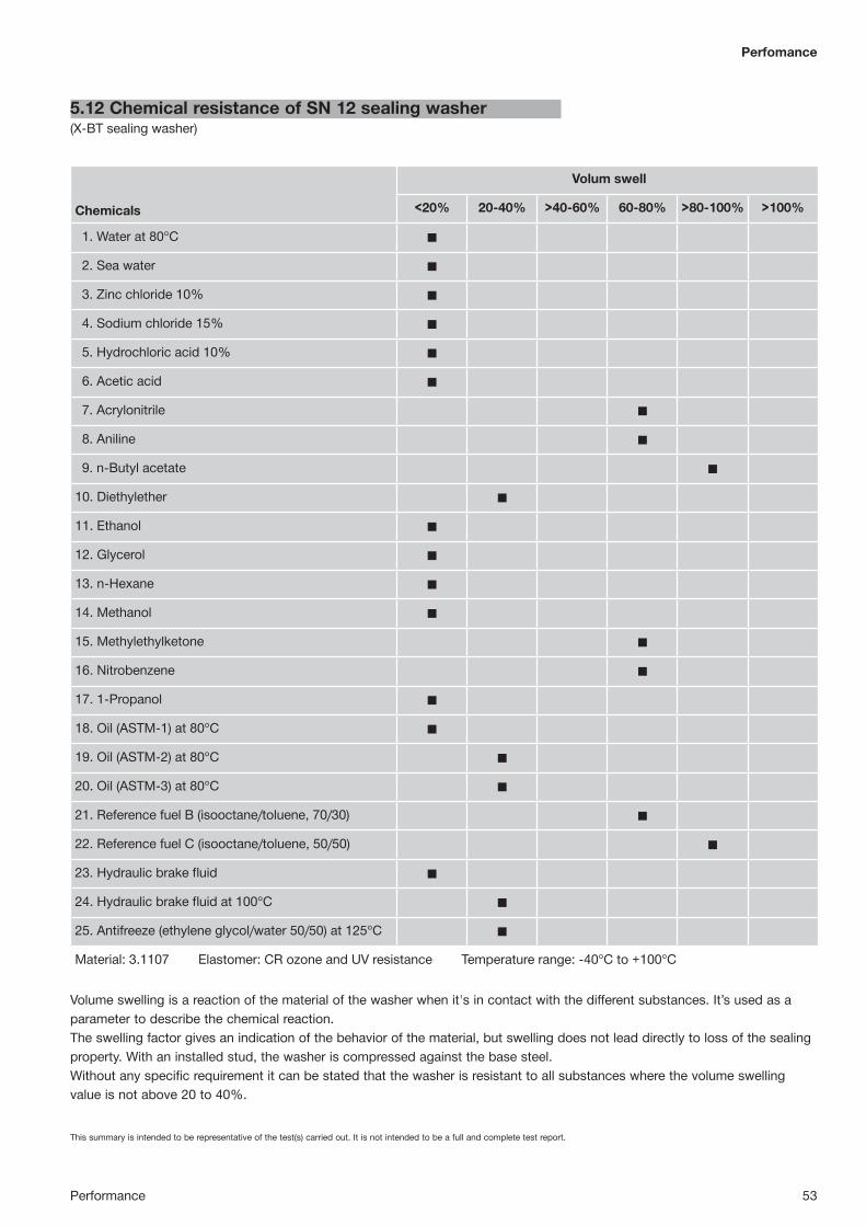
This summary is intended to be representative of the test(s) carried out. It is not intended to be a full and complete test report.
Performance 53
Perfomance
Volume swelling is a reaction of the material of the washer when it's in contact with the different substances. It’s used as a parameter to describe the chemical reaction. The swelling factor gives an indication of the behavior of the material, but swelling does not lead directly to loss of the sealing property. With an installed stud, the washer is compressed against the base steel. Without any specific requirement it can be stated that the washer is resistant to all substances where the volume swelling value is not above 20 to 40%.
5.12 Chemical resistance of SN 12 sealing washer(X-BT sealing washer)
Chemicals
Volum swell
<20% 20-40% >40-60% 60-80% >80-100% >100%
1. Water at 80°C ◼
2. Sea water ◼
3. Zinc chloride 10% ◼
4. Sodium chloride 15% ◼
5. Hydrochloric acid 10% ◼
6. Acetic acid ◼
7. Acrylonitrile ◼
8. Aniline ◼
9. n-Butyl acetate ◼
10. Diethylether ◼
11. Ethanol ◼
12. Glycerol ◼
13. n-Hexane ◼
14. Methanol ◼
15. Methylethylketone ◼
16. Nitrobenzene ◼
17. 1-Propanol ◼
18. Oil (ASTM-1) at 80°C ◼
19. Oil (ASTM-2) at 80°C ◼
20. Oil (ASTM-3) at 80°C ◼
21. Reference fuel B (isooctane/toluene, 70/30) ◼
22. Reference fuel C (isooctane/toluene, 50/50) ◼
23. Hydraulic brake fluid ◼
24. Hydraulic brake fluid at 100°C ◼
25. Antifreeze (ethylene glycol/water 50/50) at 125°C ◼
Material: 3.1107 Elastomer: CR ozone and UV resistance Temperature range: -40°C to +100°C
54 Performance
5.13 Material safety data sheet for SN12 sealing washeracc. to ISO/DIS 11014
5.13.1 Identification of substance
Product details
Trade name: Plate 2.0x650x50.000 mm OE 3.1107Application of the substance / the preparation: Rubber compoundManufacturer/supplier:PHOENIX CBS GmbH, Hannoversche Straße 88, D-21079 HamburgInformation department:Conseo GmbH Abteilung Umweltschutz, Hannoversche Straße 88D-21079 Hamburg, 040 32809 2794Emergency information:0049(0)40 7667 2233
5.13.2 Composition/data on components
Chemical characterizationDescription: Mixture of the substances listed below with non-hazardous additions
Dangerous components117-81-7 bis(2-ethylhexyl) phthalate T; R 60-61 2.5-10%1309-48-4 magnesium oxide 2.5-10%1314-13-2 zinc oxide 2.5-10%68953-84-4 N,N'-Diaryl-p-phenylendiamine Xi, N; R 43-50/53 ≤ 1.0%97-39-2 1,3-di-o-tolylguanidine T; R 25 ≤ 1.0%
Additional information: For the wording of the listed risk phrases refer to section 16.
5.13.3 Hazards identification
Hazard description UInformation pertaining to particular dangers for man and environment:The product has been classified in accordance with EU directives / national laws respectively. In the version marketed, it presents no risk to the environment or to health. Following directive 67 / 54 8 EC, annex VI, point 9.3 it is not necessary to be labelled.
Classification systemThe classification was made according to the latest editions of international substances lists and expanded upon from company and literature data.
NFPA ratings (scale 0 - 4)Health = 0, Fire = 0, Reactivity = 0
HMIS-ratings (scale 0–4)Health = *0, Fire = 0, Reactivity = 0
Performance 55
Perfomance
5.13.4 First aid measures
General information: No special measures required.After inhalation: Supply fresh air; consult doctor in case of complaints.After skin contact: Generally the product does not irritate the skin.After eye contact: Rinse opened eye for several minutes under running water.After swallowing: If symptoms persist consult doctor.
5.13.5 Fire fighting measures
Suitable extinguishing agents:CO2, extinguishing powder or water spray. Fight larger fires with water spray or alcohol resistant foam.
Special hazards caused by the material, its products of combustion or resulting gases:Formation of toxic gases is possible during heating or in case of fire. In case of fire, the following can be released:Carbon monoxide (CO), Sulphur dioxide (SO2), Hydrogen chloride (HCl)
Protective equipment: No special measures required.
5.13.6 Accidental release measures
Person-related safety precautions: Not required.Measures for environmental protection: No special measures required.Measures for cleaning/collecting: Pick up mechanically.Additional information: No dangerous substances are released.
5.13.7 Handling and storage
HandlingInformation for safe handling: No special measures required.Information about protection against explosions and fires: No special measures required.
StorageRequirements to be met by storerooms and receptacles: No special requirements.Information about storage in one common storage facility: Not required.Further information about storage conditions: None.
56 Performance
5.13.8 Exposure controls and personal protection
Additional information about design of technical systems: No further data; see item 7.Components with limit values that require monitoring at the workplace:When working with the product N-nitrosamines can be liberated
117-81-7 bis(2-ethylhexyl) phthalatePEL 5 mg/m³REL Short-term value: 10 mg/m³ Long-term value: 5 mg/m³TLV 5 mg/m³1309-48-4 magnesium oxidePEL 15* mg/m³ fumeTLV 10 mg/m³ fume1314-13-2 zinc oxidePEL 15*; 5** mg/m³ Dust only *Total dust **Respirable dustREL Short-term value: C 15*;10** mg/m³ Long-term value: 5,5** mg/m³ Zinc oxide, Dust only; *15-min Dust only; **ZincTLV Short-term value: 10** mg/m³ Long-term value: 10* 5** mg/m³ *dust **fume; *NIC-2 R; *10 R; *((e))
Additional informationThe lists that were valid during formulation were used as a basis.
Personal protective equipmentGeneral protective and hygienic measures:The usual precautionary measures for handling chemicals should be followed.
Protection of handsThe glove material must be impermeable and resistant to the product / the sub-stance / the preparation.As no test information is available, no recommendation about glove material can be given for the product/ the preparation/ the chemical mixture.Selection of the glove material on consideration of the penetration times, rates of diffusion and the degradation.
Glove materialSelection of suitable gloves does not only depend on the material, but also on fur-ther marks of quality and varies from manufacturer to manufacturer. As the product is a preparation of several substances, the resistance of the glove material can not be calculated in advance and must therefore be checked prior to the application.
Penetration time of glove materialThe exact breaktrough time must be stated by the manufacturer of the protective gloves and must be observed.
Eye protectionNot required.

Performance 57
Perfomance
5.13.9 Physical and chemical properties
General InformationForm: SolidColor: According to product specificationOdor: CharacteristicChange in conditionMelting point/melting range: Undetermined.Boiling point/boiling range: Undetermined.Flash point: Not applicable.Ignition temperature: 370.0°C (698°F)Auto igniting: Product is not self-igniting.Danger of explosion: Product does not present an explosion hazard.Density at 20°C (68°F): 1.380 g/cm³Solubility in / miscibility withwater: Insoluble.Solvent content:Organic solvents: 0.0 %Solids content: 94.5 %
5.13.10 Stability and reactivity
Thermal decomposition / conditions to be avoidedNo decomposition if used according to specifications.
Dangerous reactions No dangerous reactions known.
Dangerous products of decompositionHydrogen chloride (HCl)Toxic pyrolysis products.
5.13.11 Toxicological information
Acute toxicityLD/LC50 values that are relevant for classification117-81-7 bis(2-ethylhexyl) phthalateOral LD50 30600 mg/kg (rat)Dermal LD50 25000 mg/kg (rbt)
Primary irritant effectOn the skin: No irritant effect.On the eye: No irritating effect.Sensitization: No sensitizing effects known.
Additional toxicological informationThe product is not subject to classification according to internally approved calculation methods for preparations.When used and handled according to specifications, the product does not have any harmful effects according to our experience and the information provided to us.
58 Performance
5.13.12 Ecological information
General notesGenerally not hazardous to water
5.13.13 Disposal considerations
Product
RecommendationSmaller quantities can be disposed of with household waste.Can be disposed of under observance of the technical instructions after consultation with the local authorities and waste disposers. Use one of the following waste key numbers.
Uncleaned packagingsRecommendation: Disposal must be according to official regulations.
5.13.14 Transport information
DOT regulations:Hazard class: -Land transport ADR/RID (cross-border):ADR/RID class: -Maritime transport IMDG:IMDG Class: -Marine pollutant: NoAir transport ICAO-TI and IATA-DGR:ICAO/IATA Class: -
Transport/additional information:Not hazardous according to the above specifications.

Performance 59
Perfomance
5.13.15 Regulations
SaraSection 355 (extremely hazardous substances):None of the constituents are listed.Section 313 (Specific toxic chemical listings):117-81-7 bis(2-ethylhexyl) phthalateTSCA (Toxic Substances Control Act):9010-98-4 Polychloropren CR117-81-7 bis(2-ethylhexyl) phthalate1309-48-4 magnesium oxide1314-13-2 zinc oxide97-39-2 1,3-di-o-tolylguanidine101-67-7 bis(4-octylphenyl)amine97-74-5 tetramethylthiuram monosulphide
Proposition 65Chemicals known to cause cancer:117-81-7 bis(2-ethylhexyl) phthalateChemicals known to cause reproductive toxicity:None of the constituents are listed.
Cancerogenity categoriesEPA (Environmental Protection Agency)117-81-7 bis(2-ethylhexyl) phthalate B21314-13-2 zinc oxide DIARC (International Agency for Research on Cancer)117-81-7 bis(2-ethylhexyl) phthalate 2BNTP (National Toxicology Program)117-81-7 bis(2-ethylhexyl) phthalate RTLV (Threshold Limit Value established by ACGIH)117-81-7 bis(2-ethylhexyl) phthalate A3MAK (GermanMaximumWorkplace Concentration)None of constituents are listed.NIOSH-Ca (National Institute for Occupational Safety and Health)117-81-7 bis(2-ethylhexyl) phthalateOSHA-Ca (Occupational Safety & Health Administration)None of the constituents are listed.
Product-related hazard informationObserve the general safety regulations when handling chemicals.The product has been classified in accordance with EU directives / national laws respectively. In the version marketed, it presents no risk to the environment or to health. Following directive 67 / 548 EC, annex VI, point 9.3 it is not necessary to be labelled.

60 Performance
Perfomance
Hazard symbols
U
National regulations
Technical instructions (air)
Class Share in %I 0.4NK 5.5
Water hazard class: Generally not hazardous to water.
Other regulations, limitations and prohibitive regulationsSubject to the regulations for N-Nitrosamines.
5.13.16 Other information
This information is based on our present knowledge. However, this shall not constitute a guarantee for any specific product features and shall not establish a legally valid contractual relationship.
Department issuing MSDS: Conseo GmbH Abteilung UmweltschutzContact: Hr. Dr. Kräßig / Hr. Dr. Laugwitz

61

62 Approvals
6. APPROVALS
6.1 American Bureau of Shipping (ABS)
Certificate Number: 16-HS1545448-PDA01/SEP/2016
Confirmation of Product Type ApprovalPlease refer to the "Service Restrictions" shown below to determine if Unit Certification is required for this product.This certificate reflects the information on the product in the ABS Records as of the date and time the certificate isprinted.Pursuant to the Rules of the American Bureau of Shipping (ABS), the manufacturer of the below listed product helda valid Manufacturing Assessment (MA) with expiration date of 30/AUG/2021. The continued validity of theManufacturing Assessment is dependent on completion of satisfactory audits as required by the ABS Rules.And; a Product Design Assessment (PDA) valid until 14/AUG/2021 subject to continued compliance with the Rulesor standards used in the evaluation of the product.The above entitle the product to be called Product Type Approved.The Product Design Assessment is valid for products intended for use on ABS classed vessels, MODUs or facilitieswhich are in existence or under contract for construction on the date of the ABS Rules used to evaluate theProduct.ABS makes no representations regarding Type Approval of the Product for use on vessels, MODUs or facilitiesbuilt after the date of the ABS Rules used for this evaluation.Due to wide variety of specifications used in the products ABS has evaluated for Type Approval, it is part of ourcontract that; whether the standard is an ABS Rule or a non-ABS Rule, the Client has full responsibility forcontinued compliance with the standard.
Product Name: Fastening SystemModel Name(s): Stainless powder-actuated Hilti X-BT threaded fasteners.
Presented to:HILTI AKTIENGESELLSCHAFTFELDKIRCHERSTR. 100,Liechtenstein
Intended Service: For fastening of fastened materials to base materials of carbon steel or stainlesssteel in the Ship and Shipbuilding environment and in Offshore Structures.
Description: Fasteners Models: X-BT Models (M6 & W6, M8, M10, & W10), X-BT-ER Models,X-BT-MR-N Models, Composite Fasteners: X-FCM-R & X-FCM-M Fasteners: X-BTM6-24-6 SN-12-R, X-BT W6-24-6 SN-12-R, X-BT M8-15-6-R, X-BT M10-24-6-R,X-BT W10-24-6-R, X-BT M8-15-6 SN12-R, X-BT M10-24-6 SN12-R, X-BTW10-24-6 SN12-R, X-BT-MR-N M8 fasteners, Grounding and bonding equipment:X-BT-ER M10/3 SN 4, X-BT-ER W10/3 SN 4, X-BT-ER M8/7 SN 4, X-BT-ER M6/7SN 4, X-BT-ER W6/7 SN 4. Drilling Tool: XBT 4000-A, SF BT 22-A or SF BT 18-A& TX-BT 4/7 drills, Fastening Tool: DX 351-BT & DX 351-BTG Corrosion resistantsteel threaded studs and accessories whereby fastening are made by usingpowder actuated tools to drive the fasteners into their final positions through apre-drilled hole and without having to penetrate the base materials, in a process ofpressing and fusing. Composite fasteners are either made from stainless material(X-FCM-R) or from duplex coated carbon steel (X-FCM-M)
Tier: 3Ratings: 1. Refer to "Hilti X-BT Threaded Fastener Specification 07-2015" for the
recommended maximum loading in tension, shear, moment and torque, inassociation with the 'Conditions for recommended loads' specified therein. 2.Service Temperature: - 40 to 100 Celsius.
Service Restrictions: Unit Certification is not required for this product. If the manufacturer or purchaser
09/01/2016 12:38:20 AM Copyright 2001 American Bureau of Shipping. All rights reserved. Page 1 of 3
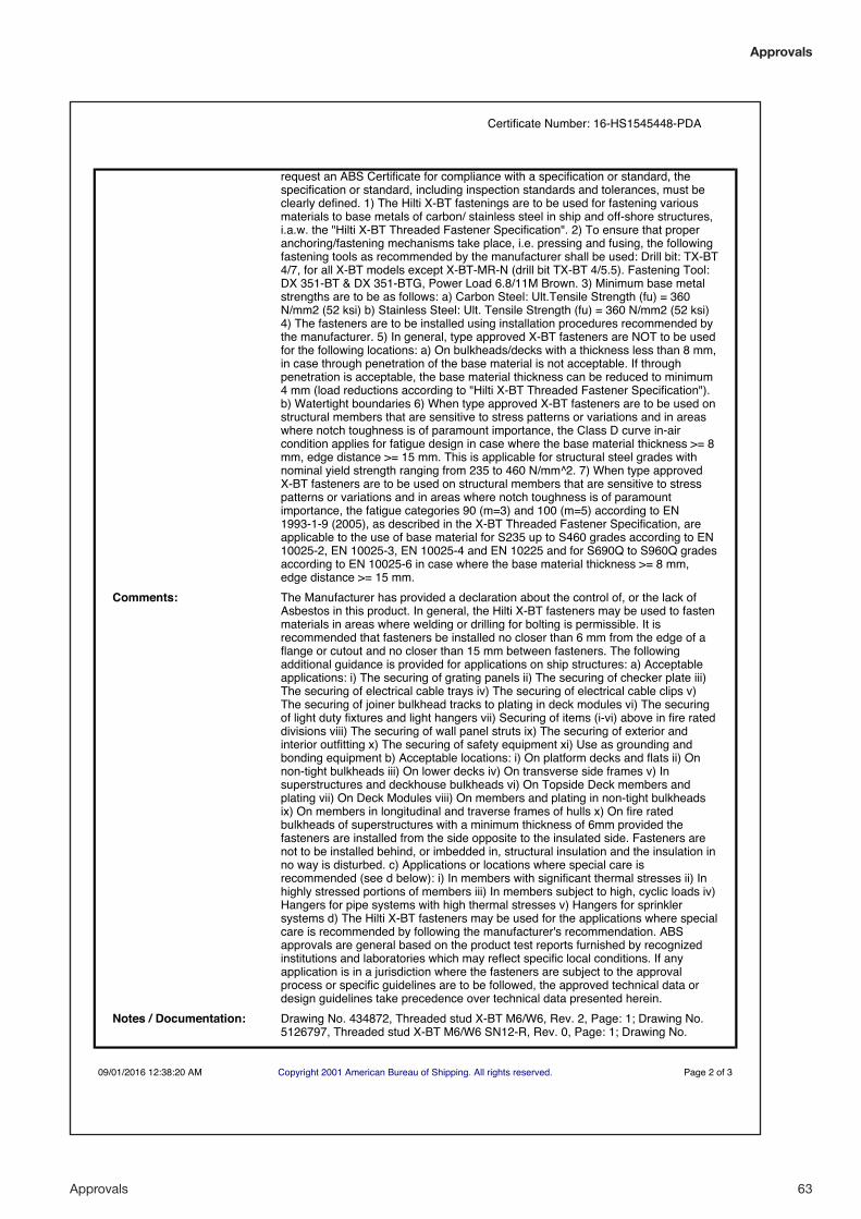
Approvals 63
Approvals
request an ABS Certificate for compliance with a specification or standard, thespecification or standard, including inspection standards and tolerances, must beclearly defined. 1) The Hilti X-BT fastenings are to be used for fastening variousmaterials to base metals of carbon/ stainless steel in ship and off-shore structures,i.a.w. the "Hilti X-BT Threaded Fastener Specification". 2) To ensure that properanchoring/fastening mechanisms take place, i.e. pressing and fusing, the followingfastening tools as recommended by the manufacturer shall be used: Drill bit: TX-BT4/7, for all X-BT models except X-BT-MR-N (drill bit TX-BT 4/5.5). Fastening Tool:DX 351-BT & DX 351-BTG, Power Load 6.8/11M Brown. 3) Minimum base metalstrengths are to be as follows: a) Carbon Steel: Ult.Tensile Strength (fu) = 360N/mm2 (52 ksi) b) Stainless Steel: Ult. Tensile Strength (fu) = 360 N/mm2 (52 ksi)4) The fasteners are to be installed using installation procedures recommended bythe manufacturer. 5) In general, type approved X-BT fasteners are NOT to be usedfor the following locations: a) On bulkheads/decks with a thickness less than 8 mm,in case through penetration of the base material is not acceptable. If throughpenetration is acceptable, the base material thickness can be reduced to minimum4 mm (load reductions according to "Hilti X-BT Threaded Fastener Specification").b) Watertight boundaries 6) When type approved X-BT fasteners are to be used onstructural members that are sensitive to stress patterns or variations and in areaswhere notch toughness is of paramount importance, the Class D curve in-aircondition applies for fatigue design in case where the base material thickness >= 8mm, edge distance >= 15 mm. This is applicable for structural steel grades withnominal yield strength ranging from 235 to 460 N/mm^2. 7) When type approvedX-BT fasteners are to be used on structural members that are sensitive to stresspatterns or variations and in areas where notch toughness is of paramountimportance, the fatigue categories 90 (m=3) and 100 (m=5) according to EN1993-1-9 (2005), as described in the X-BT Threaded Fastener Specification, areapplicable to the use of base material for S235 up to S460 grades according to EN10025-2, EN 10025-3, EN 10025-4 and EN 10225 and for S690Q to S960Q gradesaccording to EN 10025-6 in case where the base material thickness >= 8 mm,edge distance >= 15 mm.
Comments: The Manufacturer has provided a declaration about the control of, or the lack ofAsbestos in this product. In general, the Hilti X-BT fasteners may be used to fastenmaterials in areas where welding or drilling for bolting is permissible. It isrecommended that fasteners be installed no closer than 6 mm from the edge of aflange or cutout and no closer than 15 mm between fasteners. The followingadditional guidance is provided for applications on ship structures: a) Acceptableapplications: i) The securing of grating panels ii) The securing of checker plate iii)The securing of electrical cable trays iv) The securing of electrical cable clips v)The securing of joiner bulkhead tracks to plating in deck modules vi) The securingof light duty fixtures and light hangers vii) Securing of items (i-vi) above in fire rateddivisions viii) The securing of wall panel struts ix) The securing of exterior andinterior outfitting x) The securing of safety equipment xi) Use as grounding andbonding equipment b) Acceptable locations: i) On platform decks and flats ii) Onnon-tight bulkheads iii) On lower decks iv) On transverse side frames v) Insuperstructures and deckhouse bulkheads vi) On Topside Deck members andplating vii) On Deck Modules viii) On members and plating in non-tight bulkheadsix) On members in longitudinal and traverse frames of hulls x) On fire ratedbulkheads of superstructures with a minimum thickness of 6mm provided thefasteners are installed from the side opposite to the insulated side. Fasteners arenot to be installed behind, or imbedded in, structural insulation and the insulation inno way is disturbed. c) Applications or locations where special care isrecommended (see d below): i) In members with significant thermal stresses ii) Inhighly stressed portions of members iii) In members subject to high, cyclic loads iv)Hangers for pipe systems with high thermal stresses v) Hangers for sprinklersystems d) The Hilti X-BT fasteners may be used for the applications where specialcare is recommended by following the manufacturer's recommendation. ABSapprovals are general based on the product test reports furnished by recognizedinstitutions and laboratories which may reflect specific local conditions. If anyapplication is in a jurisdiction where the fasteners are subject to the approvalprocess or specific guidelines are to be followed, the approved technical data ordesign guidelines take precedence over technical data presented herein.
Notes / Documentation: Drawing No. 434872, Threaded stud X-BT M6/W6, Rev. 2, Page: 1; Drawing No.5126797, Threaded stud X-BT M6/W6 SN12-R, Rev. 0, Page: 1; Drawing No.
Certificate Number: 16-HS1545448-PDA
09/01/2016 12:38:20 AM Copyright 2001 American Bureau of Shipping. All rights reserved. Page 2 of 3
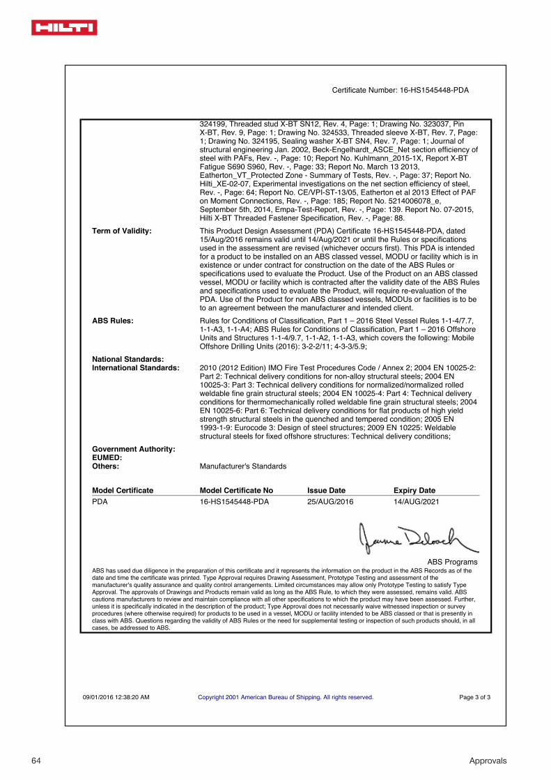
64 Approvals
324199, Threaded stud X-BT SN12, Rev. 4, Page: 1; Drawing No. 323037, PinX-BT, Rev. 9, Page: 1; Drawing No. 324533, Threaded sleeve X-BT, Rev. 7, Page:1; Drawing No. 324195, Sealing washer X-BT SN4, Rev. 7, Page: 1; Journal ofstructural engineering Jan. 2002, Beck-Engelhardt_ASCE_Net section efficiency ofsteel with PAFs, Rev. -, Page: 10; Report No. Kuhlmann_2015-1X, Report X-BTFatigue S690 S960, Rev. -, Page: 33; Report No. March 13 2013,Eatherton_VT_Protected Zone - Summary of Tests, Rev. -, Page: 37; Report No.Hilti_XE-02-07, Experimental investigations on the net section efficiency of steel,Rev. -, Page: 64; Report No. CE/VPI-ST-13/05, Eatherton et al 2013 Effect of PAFon Moment Connections, Rev. -, Page: 185; Report No. 5214006078_e,September 5th, 2014, Empa-Test-Report, Rev. -, Page: 139. Report No. 07-2015,Hilti X-BT Threaded Fastener Specification, Rev. -, Page: 88.
Term of Validity: This Product Design Assessment (PDA) Certificate 16-HS1545448-PDA, dated15/Aug/2016 remains valid until 14/Aug/2021 or until the Rules or specificationsused in the assessment are revised (whichever occurs first). This PDA is intendedfor a product to be installed on an ABS classed vessel, MODU or facility which is inexistence or under contract for construction on the date of the ABS Rules orspecifications used to evaluate the Product. Use of the Product on an ABS classedvessel, MODU or facility which is contracted after the validity date of the ABS Rulesand specifications used to evaluate the Product, will require re-evaluation of thePDA. Use of the Product for non ABS classed vessels, MODUs or facilities is to beto an agreement between the manufacturer and intended client.
ABS Rules: Rules for Conditions of Classification, Part 1 – 2016 Steel Vessel Rules 1-1-4/7.7,1-1-A3, 1-1-A4; ABS Rules for Conditions of Classification, Part 1 – 2016 OffshoreUnits and Structures 1-1-4/9.7, 1-1-A2, 1-1-A3, which covers the following: MobileOffshore Drilling Units (2016): 3-2-2/11; 4-3-3/5.9;
National Standards:International Standards: 2010 (2012 Edition) IMO Fire Test Procedures Code / Annex 2; 2004 EN 10025-2:
Part 2: Technical delivery conditions for non-alloy structural steels; 2004 EN10025-3: Part 3: Technical delivery conditions for normalized/normalized rolledweldable fine grain structural steels; 2004 EN 10025-4: Part 4: Technical deliveryconditions for thermomechanically rolled weldable fine grain structural steels; 2004EN 10025-6: Part 6: Technical delivery conditions for flat products of high yieldstrength structural steels in the quenched and tempered condition; 2005 EN1993-1-9: Eurocode 3: Design of steel structures; 2009 EN 10225: Weldablestructural steels for fixed offshore structures: Technical delivery conditions;
Government Authority:EUMED:Others: Manufacturer's Standards
Model Certificate Model Certificate No Issue Date Expiry DatePDA 16-HS1545448-PDA 25/AUG/2016 14/AUG/2021
ABS ProgramsABS has used due diligence in the preparation of this certificate and it represents the information on the product in the ABS Records as of thedate and time the certificate was printed. Type Approval requires Drawing Assessment, Prototype Testing and assessment of themanufacturer's quality assurance and quality control arrangements. Limited circumstances may allow only Prototype Testing to satisfy TypeApproval. The approvals of Drawings and Products remain valid as long as the ABS Rule, to which they were assessed, remains valid. ABScautions manufacturers to review and maintain compliance with all other specifications to which the product may have been assessed. Further,unless it is specifically indicated in the description of the product; Type Approval does not necessarily waive witnessed inspection or surveyprocedures (where otherwise required) for products to be used in a vessel, MODU or facility intended to be ABS classed or that is presently inclass with ABS. Questions regarding the validity of ABS Rules or the need for supplemental testing or inspection of such products should, in allcases, be addressed to ABS.
Certificate Number: 16-HS1545448-PDA
09/01/2016 12:38:20 AM Copyright 2001 American Bureau of Shipping. All rights reserved. Page 3 of 3
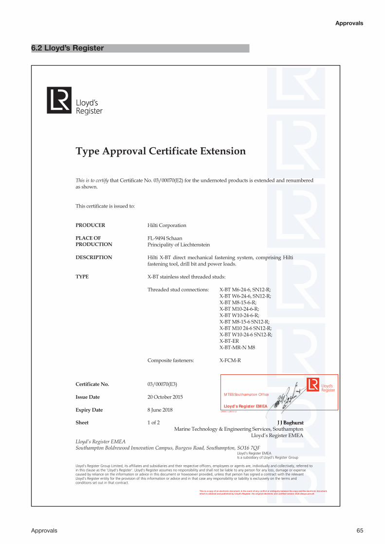
Approvals 65
Approvals
6.2 Lloyd’s Register
This is a copy of an electronic document. In the event of any conflict or ambiguity between the copy and the electronic document,which is retained and published by Lloyd's Register, the original electronic and certified version shall always prevail.
Certificate No. 03/00070(E3) Issue Date 20 October 2015 Expiry Date 8 June 2018 Sheet 1 of 2 J J Baghurst Marine Technology & Engineering Services, Southampton Lloyd’s Register EMEA Lloyd’s Register EMEA Southampton Boldrewood Innovation Campus, Burgess Road, Southampton, SO16 7QF Lloyd's Register EMEA Is a subsidiary of Lloyd's Register Group Lloyd's Register Group Limited, its affiliates and subsidiaries and their respective officers, employees or agents are, individually and collectively, referred to in this clause as the 'Lloyd's Register'. Lloyd's Register assumes no responsibility and shall not be liable to any person for any loss, damage or expense caused by reliance on the information or advice in this document or howsoever provided, unless that person has signed a contract with the relevant Lloyd's Register entity for the provision of this information or advice and in that case any responsibility or liability is exclusively on the terms and conditions set out in that contract.
Type Approval Certificate Extension This is to certify that Certificate No. 03/00070(E2) for the undernoted products is extended and renumbered as shown. This certificate is issued to: PRODUCER Hilti Corporation PLACE OF PRODUCTION
FL-9494 Schaan Principality of Liechtenstein
DESCRIPTION Hilti X-BT direct mechanical fastening system, comprising Hilti
fastening tool, drill bit and power loads. TYPE X-BT stainless steel threaded studs:
Threaded stud connections: X-BT M6-24-6, SN12-R; X-BT W6-24-6, SN12-R; X-BT M8-15-6-R; X-BT M10-24-6-R; X-BT W10-24-6-R; X-BT M8-15-6 SN12-R; X-BT M10 24-6 SN12-R; X-BT W10-24-6 SN12-R;
X-BT-ER X-BT-MR-N M8
Composite fasteners: X-FCM-R
J J Baghurst J J Baghurst
LR031.1.2013.12
Lloyd's Register EM EA
MTES Southampton Of f ice

66 Approvals
This is a copy of an electronic document. In the event of any conflict or ambiguity between the copy and the electronic document,which is retained and published by Lloyd's Register, the original electronic and certified version shall always prevail.
Certificate No. 03/00070(E3) Issue Date 20 October 2015 Expiry Date 8 June 2018 Sheet 2 of 2 J J Baghurst Marine Technology & Engineering Services, Southampton Lloyd’s Register EMEA Lloyd’s Register EMEA Southampton Boldrewood Innovation Campus, Burgess Road, Southampton, SO16 7QF Lloyd's Register EMEA Is a subsidiary of Lloyd's Register Group Lloyd's Register Group Limited, its affiliates and subsidiaries and their respective officers, employees or agents are, individually and collectively, referred to in this clause as the 'Lloyd's Register'. Lloyd's Register assumes no responsibility and shall not be liable to any person for any loss, damage or expense caused by reliance on the information or advice in this document or howsoever provided, unless that person has signed a contract with the relevant Lloyd's Register entity for the provision of this information or advice and in that case any responsibility or liability is exclusively on the terms and conditions set out in that contract.
APPLICATION For use in fastening to steel in marine, offshore and industrial
environments. Including structural steel Grades S690 and S960 in compliance with Eurocode 3 Part 1-9 (EN 1993-1-9)
SPECIFIED STANDARDS Hilti X-BT Threaded Fastener Specification;
Hilti Direct Fastening technology manual, Product Information. OTHER CONDITIONS 1. This Type Approval certificate is to be read in conjunction
with LR Technical Report no. 2003/CSG/TI/6331.
2. The minimum strength of the base material must be as stated in the Hilti X-BT Threaded Fastener Specification.
3. The end user must ensure that the base and fastened materials possess adequate corrosion resistance for the environments in which they are to be used.
4. For use on LR Classed ships, the locations and systems for
which they are to be used are to be subject to a ship specific agreement.
5. Fatigue classification in accordance with EN 1993-1-9:2005
– Eurocode 3: Design of steel structures, is equivalent to category 90 m=3, and category 100 m=5,
“This Certificate is not valid for equipment, the design, ratings or operating parameters of which have been varied from the specimen tested. The manufacturer should notify Lloyd’s Register EMEA of any modification or changes to the equipment in order to obtain a valid certificate.” The attached Design Appraisal Document No. 03/00070(E3) and its supplementary Type Approval Terms and Conditions form part of this Certificate. All other details remain as the previous Certificate No. 03/00070(E2) to which this extension should be attached.
J J Baghurst J J Baghurst Marine Technology & Engineering Services, Southampton Marine Technology & Engineering Services, Southampton
LR031.1.2013.12
Lloyd's Register EM EA
MTES Southampton Of f ice
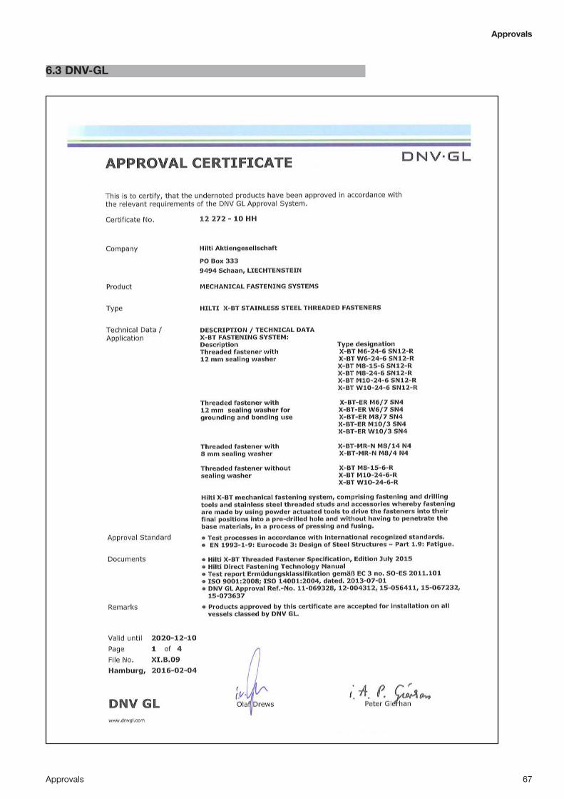
Approvals 67
Approvals
6.3 DNV-GL

68 Approvals
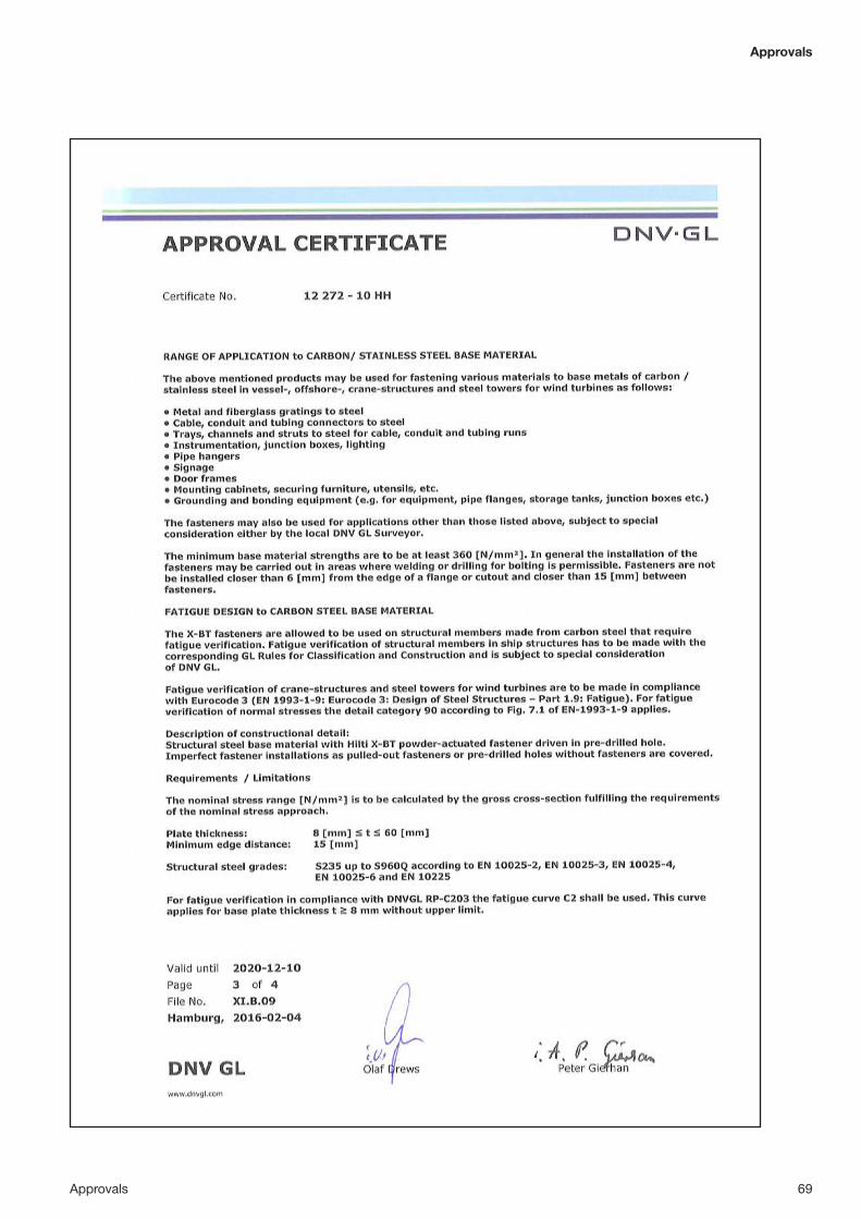
Approvals 69
Approvals

70 Approvals

Approvals 71
Approvals
6.4 Russian Maritime Register

72 Approvals

Approvals 73
Approvals
6.5 Bureau Veritas (BV)
This certificate is issued to
Hilti AktiengesellschaftSCHAAN - LIECHTENSTEIN
for the type of product
MECHANICAL FASTENING SYSTEMHILTI X-BT MECHANICAL FASTENING SYSTEM
Requirements:BUREAU VERITAS Rules for the Classification of Steel ShipsBUREAU VERITAS Rules for the Classification of Offshore UnitsBUREAU VERITAS Rules for the Classification of Naval ShipsBUREAU VERITAS Rules for the Classification of Yachts
Page 1 / 4
Certificate number: 23498/B0 BV
File number: ACM 139/1905/1
Product code: 0226H
This certificate is not valid when presented without thefull attached schedule composed of 7 sections
www.veristar.com
TYPE APPROVAL CERTIFICATE
This certificate is issued to attest that BUREAU VERITAS did undertake the relevant approval procedures for the product identified above whichwas found to comply with the relevant requirements mentioned above.
This certificate will expire on: 13 Jan 2021
For BUREAU VERITAS,
At BV HAMBURG, on 13 Jan 2016,
Adama Diene
This certificate remains valid until the date stated above, unless cancelled or revoked, provided the conditions indicated in the subsequent page(s) are compliedwith and the product remains satisfactory in service. This certificate will not be valid if the applicant makes any changes or modifications to the approved product,which have not been notified to, and agreed in writing with BUREAU VERITAS. Should the specified regulations or standards be amended during the validity ofthis certificate, the product(s) is/are to be re-approved prior to it/they being placed on board vessels to which the amended regulations or standards apply. Thiscertificate is issued within the scope of the General Conditions of BUREAU VERITAS Marine & Offshore Division available on the internet site www.veristar.com.Any Person not a party to the contract pursuant to which this document is delivered may not assert a claim against BUREAU VERITAS for any liability arising outof errors or omissions which may be contained in said document, or for errors of judgement, fault or negligence committed by personnel of the Society or of itsAgents in establishment or issuance of this document, and in connection with any activities for which it may provide.
The electronic version is available at: http://www.veristarnb.com/veristarnb/jsp/viewPublicPdfTypec.jsp?id=bgigzzhevsBV Mod. Ad.E 530 October 2014 This certificate consists of 4 page(s)

74 Approvals
THE SCHEDULE OF APPROVAL
1. PRODUCT DESCRIPTION :
Hilti X-BT mechanical fastening system, comprising Hilti fastening tool, power load, drill bit, stainless steel threaded studsand accessories, whereby fastenings are made by using powder-actuated tools to drive the fasteners into their final positions intoa pre-drilled hole and without having to penetrate the base materials in a process of pressing and fusing.
Identification of Components:Component Name Designation
X-BT M6-24-6 SN12-R Stainless steel threaded stud M6 with sealing washer
X-BT W6-24-6 SN12-R Stainless steel threaded stud W6 with sealing washer
X-BT M8-15-6-R Stainless steel threaded stud M8
X-BT M8-15-6 SN12-R Stainless steel threaded stud M8 with sealing washer
X-BT M10-24-6-R Stainless steel threaded stud M10
X-BT M10-24-6 SN12-R Stainless steel threaded stud M10 with sealing washer
X-BT W10-24-6-R Stainless steel threaded stud 3/8"
X-BT W10-24-6 SN12-R Stainless steel threaded stud 3/8" with sealing washer
X-BT-ER M6/7 SN 4 Stainless steel threaded stud for electrical connections
X-BT-ER W6/7 SN 4 Stainless steel threaded stud for electrical connections
X-BT-ER M8/7 SN 4 Stainless steel threaded stud for electrical connections
X-BT-ER M10/3 SN 4 Stainless steel threaded stud for electrical connections
X-BT-ER W10/3 SN 4 Stainless steel threaded stud for electrical connections
X-BT-MR-N M8/4 N 4 Stainless steel threaded stud for fastening applications to cranes
X-BT-MR-N M8/14 N 4 Stainless steel threaded stud for fastening applications to cranes
X-FCM-R 25/30 Stainless steel grating fastener
X-FCM-R 1 – 1 1/4 Stainless steel grating fastener
X-FCM-R 35/40 Stainless steel grating fastener
X-FCM-R 45/50 Stainless steel grating fastener
X-FCM-M 25/30 Grating fastener, carbon steel, duplex coated
X-FCM-M 1 – 1 1/4 Grating fastener, carbon steel, duplex coated
X-FCM-M 35/40 Grating fastener, carbon steel, duplex coated
X-FCM-M 45/50 Grating fastener, carbon steel, duplex coated
TX-BT 4/7 4/7 step drill bit
TX-BT 4/5.5 4/5.5 step drill bit (for models X-BT-MR-N M8/14 N4 andXBT-MR-N M8/4 N4)
DX 351 BTG Fastening tool
X-351-BT FG G Components for fastening tool
X-351-BT P G Components for fastening tool
DX 351 BT Fastening tool
X-351-BT FG M1024 Components for fastening tool
X-351-BT FG W1024 Components for fastening tool
X-351-BT P 1024 Components for fastening tool
6.8/11M brown Cartridge
2. DOCUMENTS AND DRAWINGS :
Designation Revision / Date
Hilti X-BT Threaded Fastener Specification Edition July2015
Hilti Direct Fastening Technology Manual Edition May 2015
Technical documentation on Hilti X-BT direct fastening system Edition May 2011
Page 2 / 4
Certificate number: 23498/B0 BV
The electronic version is available at: http://www.veristarnb.com/veristarnb/jsp/viewPublicPdfTypec.jsp?id=bgigzzhevs
BV Mod. Ad.E 530 October 2014 This certificate consists of 4 page(s)

Approvals 75
Approvals
3. TEST REPORTS :
According to the following tests:- Test Report No. 257/09 at Bautechnische Versuchsanstalt HTL Rankweil/AUSTRIA on 27.09.2010- Investigation Report 901 8035 000/Bf at MPA University of Stuttgart/GERMANY on 02.11.2009- Test Report No. 095/10 at Bautechnische Versuchsanstalt HTL Rankweil/AUSTRIA on 11.06.2010- Report No. 09-IK-0208.32V3_e at Electrosuisse, Fehraltorf/SWITZERLAND on 06.04.2011- Test Report No. CF-791 at Dehn+Söhne GmbH+Co. KG, Neumarkt/GERMANY on 22.03.2006- Report No. 2010-57X at University of Stuttgart/GERMANY on 28.12.2010- Test Report No. TWU FSRL-13/09 at Hilti Corporation, Schaan/LIECHTENSTEIN on 20.04.2010- Test Report No. 453´150/1e at EMPA, Dübendorf/SWITZERLAND on 09.03.2010- Test Report No. 453´150/2e at EMPA, Dübendorf/SWITZERLAND on 11.05.2010- Test Report No. 453´150/3e at EMPA, Dübendorf/SWITZERLAND on 10.06.2010- Test Report No. 455´377/e at EMPA, Dübendorf/SWITZERLAND on 08.12.2010- Report No. 09-IK-0208.C01 at Electrosuisse, Fehraltorf/SWITZERLAND on 22.05.2015- Report No. 2015-1X at University of Stuttgart/GERMANY on 15.01.2015- Test Report No. 5214006078/e at EMPA, Dübendorf/SWITZERLAND on 07.10.2014
4. APPLICATION / LIMITATION :
4.1 The mechanical fastening system is intended for fastening applications in shipbuilding, offshore and crane structures as faras the BUREAU VERITAS Rules are complied with:- Metal and fiberglass grating- Cable, conduit and tubing connectors- Trays, channels and struts for cable, conduit and tubing runs- Instrumentation, Junction Boxes, Lighting- Pipe hangers- Signage- Door frames- Mounting cabinets, securing furniture, utensils, etc.- Earthing (Grounding), bonding (e.g. for equipment, pipe flanges, storage tanks, junction boxes etc.)to coated steel and/or high strength steel and to structural steel according to EN 100025 (S235, S275, S355, S420, S460,S690, S960).
4.2 The minimum thickness of the base material is not to be less than 8 mm, through penetration of base steel is not allowed.
4.3 The maximum thickness of the fastened material is for the X-BT M8 not to be more than 7.0 mm, for the X-BT M6 / X-BTW6 not to be more than 14.0 mm and for the X-BT M10 / X-BT W10 not to be more than 15.0 mm.
4.4 The minimum distance to the edge of a flange or cutout is not to be less than 6 mm and the minimum spacing betweenfasteners is not to be less than 15 mm.
4.5 The minimum yield strength of the base steel is not to be less than 235 N/mm^2 and the minimum tensile strength is notto be less than 340 N/mm^2.
4.6 The mechanical fastening system may be used in areas where drilling for bolting is permissible.
4.7 The maximum tightening torque of grating disc or nut fitted to the threaded fastener is not to be more than 8 Nm.
4.8 The fasteners are not to be used on structural members requiring fatigue verification.
4.9 The manufacturer’s assembly instructions and recommendations are to be complied with.
5. PRODUCTION SURVEY REQUIREMENTS :
5.1 The mechanical fastening systems are to be supplied by the manufacturer in compliance with the type described in thiscertificate.
5.2 This type of product is within the category HBV of Bureau Veritas Rule Note NR320.
Page 3 / 4
Certificate number: 23498/B0 BV
The electronic version is available at: http://www.veristarnb.com/veristarnb/jsp/viewPublicPdfTypec.jsp?id=bgigzzhevs
BV Mod. Ad.E 530 October 2014 This certificate consists of 4 page(s)

76 Approvals
5.3 Hilti Aktiengesellschaft has to make the necessary arrangements to have its works recognised by BUREAU VERITAS incompliance with the requirements of NR320 for HBV products :Hilti Plant 1
Feldkircherstrasse 100
PO Box 333
FL-9494 Schaan
Liechtenstein
andPrecistec s.r.o.
Pod Stadionem 7
74221 Koprivnice
Czech Republic
The accessory, the grating fastener X-FCM-R and X-FCM-M, are manufactured at the following production site:WP-Wörgartner Produktions GmbH
Bahnhofstraße 21
A-6372 Oberndorf
Austria
andNingbo World broad hardware & Electrical Co., Ltd
No. 139 Xinyang Road Ditang Town Yuyao City, Zhejiang, China
315491, Ningbo City, Zhejiang Province
6. MARKING OF PRODUCT :
The mechanical fastening system should be clearly identified with:- Manufacturer’s name or logo- Type designation
7. OTHERS :
7.1 The mechanical fastening systems will be delivered with the relevant documentation / user’s guide.
7.2 This approval is given on the understanding that the Society reserves the right to require check tests to be carried out onthe units at any time and that Hilti Aktiengesellschaft, Schaan – Liechtenstein will accept full responsibility forinforming shipbuilders, ship owners or their subcontractors of the proper methods of use and general maintenance of theunits and the conditions of this approval.
7.3 This certificate supersedes the Type Approval Certificate N° 23498/A1 BV issued on 28 Mar 2012 by the Society.
*** END OF CERTIFICATE ***
Page 4 / 4
Certificate number: 23498/B0 BV
The electronic version is available at: http://www.veristarnb.com/veristarnb/jsp/viewPublicPdfTypec.jsp?id=bgigzzhevs
BV Mod. Ad.E 530 October 2014 This certificate consists of 4 page(s)

Approvals 77
Approvals
6.6 ICC Evaluation Services (ICC-ES)
A Subsidiary of
0
000
Most Widely Accepted and Trusted
ICC-ES Report ESR-2347 Reissued 12/2015
This report is subject to renewal 12/2017.
ICC-ES | (800) 423-6587 | (562) 699-0543 | www.icc-es.org
ICC-ES Evaluation Reports are not to be construed as representing aesthetics or any other attributes not specifically addressed, nor are they to be construed as an endorsement of the subject of the report or a recommendation for its use. There is no warranty by ICC Evaluation Service, LLC, express or implied, as to any finding or other matter in this report, or as to any product covered by the report.
Copyright © 2016 ICC Evaluation Service, LLC. All rights reserved.
“2014 Recipient of Prestigious Western States Seismic Policy Council (WSSPC) Award in Excellence”
Look for the trusted marks of Conformity!
DIVISION: 05 00 00—METALS SECTION: 05 05 23—METAL FASTENINGS
REPORT HOLDER:
HILTI, INC.
7250 DALLAS PARKWAY, SUITE 100 PLANO, TEXAS 75024
EVALUATION SUBJECT:
HILTI LOW-VELOCITY POWDER-ACTUATED DRIVEN THREADED STUDS FOR ATTACHMENT TO STEEL

78 Approvals
ICC-ES Evaluation Reports are not to be construed as representing aesthetics or any other attributes not specifically addressed, nor are they to be construed as an endorsement of the subject of the report or a recommendation for its use. There is no warranty by ICC Evaluation Service, LLC, express or implied, as to any finding or other matter in this report, or as to any product covered by the report.
Copyright © 2016 ICC Evaluation Service, LLC. All rights reserved. Page 1 of 6 1000
ICC-ES Evaluation Report ESR-2347Reissued December 2015
Revised December 2016This report is subject to renewal December 2017.
www.icc-es.org | (800) 423-6587 | (562) 699-0543 A Subsidiary of the International Code Council®
DIVISION: 05 00 00—METALS Section: 05 05 23—Metal Fastenings
REPORT HOLDER:
HILTI, INC.7250 DALLAS PARKWAY, SUITE 100PLANO, TEXAS 75024(800) [email protected]
EVALUATION SUBJECT:
HILTI LOW-VELOCITY POWDER-ACTUATED DRIVEN THREADED STUDS FOR ATTACHMENT TO STEEL
1.0 EVALUATION SCOPECompliance with the following codes: 2015, 2012, 2009 and 2006 International Building
Code® (IBC) 2015, 2012, 2009 and 2006 International Residential
Code® (IRC) 2013 Abu Dhabi International Building Code (ADIBC)†
†The ADIBC is based on the 2009 IBC. 2009 IBC code sections referenced in this report are the same sections in the ADIBC.
Property evaluated:Structural
2.0 USESThe Hilti Powder-Actuated Driven Threaded Studs are used as alternatives to the welds and bolts used to attach materials to structural steel, which are described in IBC Sections 2204.1 and 2204.2, respectively. The fasteners may be used for structures regulated under the IRC, when an engineered design is submitted in accordance with IRC Section R301.1.3.
3.0 DESCRIPTION3.1 General:Hilti low-velocity powder-actuated threaded studs are fasteners with male threads for attachment of building materials on one end and a pointed- or blunt-tip shank on the other end for embedment into the supporting steel. The threaded studs are available with the thread designations, shank diameters, lengths and materials shown in Table 1.3.1.1 X-EW6H and X-EW10H Threaded Studs: These pointed-tip studs are formed from carbon steel, hardened
in accordance with the manufacturer’s specifications, andzinc-plated in accordance with ASTM B633 SC 1, Type III.These studs are supplied with a plastic washer. See Figure 1 for a depiction of the fasteners.3.1.2 X-CRM8 Threaded Studs: These pointed-tip studs consist of a threaded sleeve and a drive pin. The threaded sleeve is manufactured from SAE 316 stainless steel. These studs are supplied with a plastic washer. The drive pin is manufactured from a proprietary CrNiMo alloy complying with the requirements of SAE 316. See Figure 2 for a depiction of the fastener. 3.1.3 X-ST-GR M8 Threaded Studs: These pointed-tip studs consist of a threaded sleeve and a drive pin. The threaded sleeve is manufactured from SAE 316 stainless steel. These studs are supplied with plastic washers. The drive pin is manufactured from stainless steel conforming to specifications in the manufacturer’s quality documentation. See Figure 3 for a depiction of the fastener. 3.1.4 X-BT Threaded Studs:3.1.4.1 X-BT M8, X-BT W10 and X-BT M10: These blunt tip studs consist of a threaded sleeve and a drive pin, and may have a stainless steel/bonded elastomer sealingwasher, designated SN12-R. The threaded sleeve and washer are manufactured from SAE 316 stainless steel. The drive pin is manufactured from a proprietary CrNiMo alloy complying with the requirements of SAE 316. See Figure 4 for a depiction of the fasteners.3.1.4.2 X-BT M6 and X-BT W6: These blunt tip studs are formed as a single piece from a proprietary CrNiMo alloy complying with the requirements of SAE 316 stainless steel, and have a stainless steel/bonded elastomer sealingwasher designated SN12-R. See Figure 5 for a depiction of the fasteners. 3.1.5 X-BT-MF: These blunt tip studs consist of a threaded sleeve and a drive pin, and have a combination stainless steel/bonded elastomer sealing washerdesignated SN4. They are also supplied with a plastic nut or a stainless steel nut. The drive pin is manufactured from a proprietary stainless steel conforming to specifications in the manufacturer’s quality documentation. The threaded sleeve is manufactured from glass-fiber-reinforced polyamide material. See Figure 6 for a depiction of the fasteners.3.2 Steel Substrates:Structural steel must comply with the minimum requirements of ASTM A36, ASTM A572 Grade 50 or
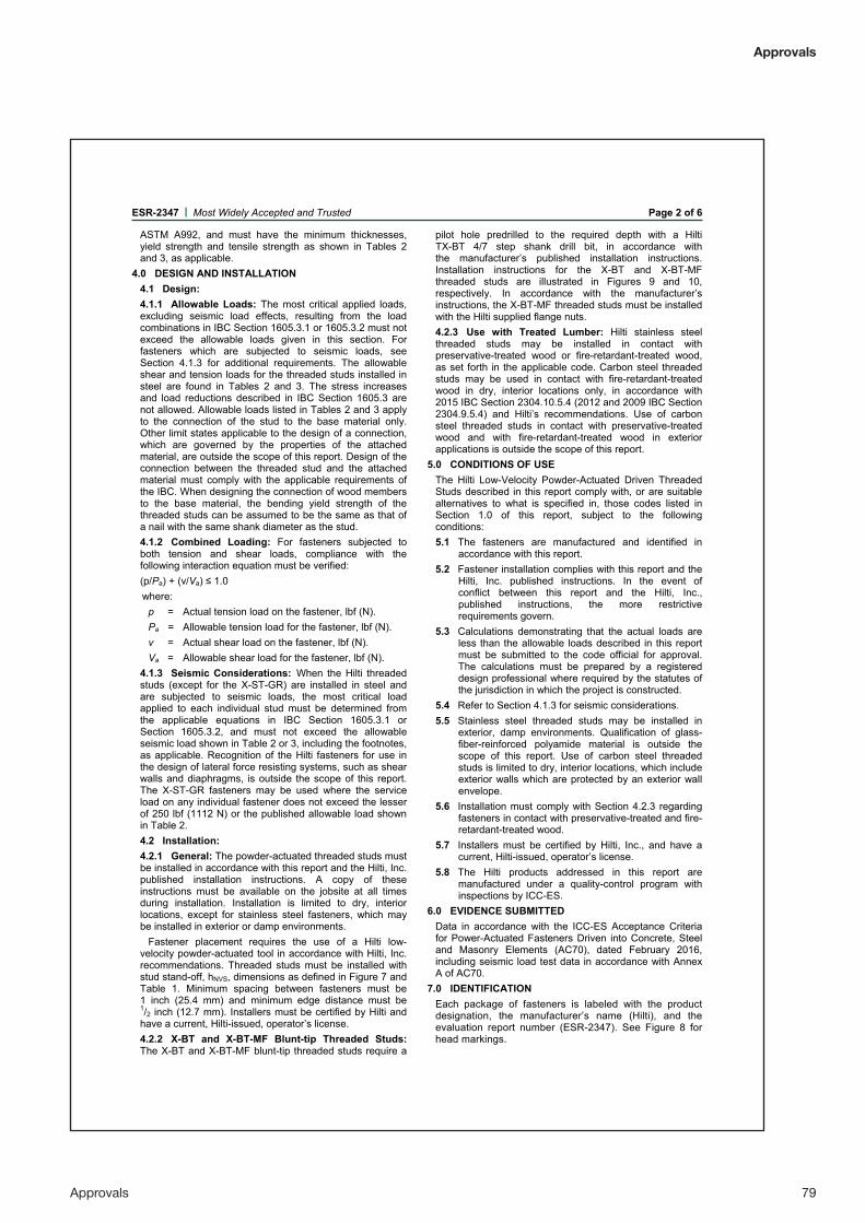
Approvals 79
Approvals
ESR-2347 | Most Widely Accepted and Trusted Page 2 of 6
ASTM A992, and must have the minimum thicknesses, yield strength and tensile strength as shown in Tables 2 and 3, as applicable.
4.0 DESIGN AND INSTALLATION 4.1 Design: 4.1.1 Allowable Loads: The most critical applied loads, excluding seismic load effects, resulting from the load combinations in IBC Section 1605.3.1 or 1605.3.2 must not exceed the allowable loads given in this section. For fasteners which are subjected to seismic loads, see Section 4.1.3 for additional requirements. The allowable shear and tension loads for the threaded studs installed in steel are found in Tables 2 and 3. The stress increases and load reductions described in IBC Section 1605.3 are not allowed. Allowable loads listed in Tables 2 and 3 apply to the connection of the stud to the base material only. Other limit states applicable to the design of a connection, which are governed by the properties of the attached material, are outside the scope of this report. Design of the connection between the threaded stud and the attached material must comply with the applicable requirements of the IBC. When designing the connection of wood members to the base material, the bending yield strength of the threaded studs can be assumed to be the same as that of a nail with the same shank diameter as the stud. 4.1.2 Combined Loading: For fasteners subjected to both tension and shear loads, compliance with the following interaction equation must be verified: (p/Pa) + (v/Va) ≤ 1.0 where:
p = Actual tension load on the fastener, lbf (N). Pa = Allowable tension load for the fastener, lbf (N). v = Actual shear load on the fastener, lbf (N). Va = Allowable shear load for the fastener, lbf (N).
4.1.3 Seismic Considerations: When the Hilti threaded studs (except for the X-ST-GR) are installed in steel and are subjected to seismic loads, the most critical load applied to each individual stud must be determined from the applicable equations in IBC Section 1605.3.1 or Section 1605.3.2, and must not exceed the allowable seismic load shown in Table 2 or 3, including the footnotes, as applicable. Recognition of the Hilti fasteners for use in the design of lateral force resisting systems, such as shear walls and diaphragms, is outside the scope of this report. The X-ST-GR fasteners may be used where the service load on any individual fastener does not exceed the lesser of 250 lbf (1112 N) or the published allowable load shown in Table 2. 4.2 Installation: 4.2.1 General: The powder-actuated threaded studs must be installed in accordance with this report and the Hilti, Inc. published installation instructions. A copy of these instructions must be available on the jobsite at all times during installation. Installation is limited to dry, interior locations, except for stainless steel fasteners, which may be installed in exterior or damp environments.
Fastener placement requires the use of a Hilti low-velocity powder-actuated tool in accordance with Hilti, Inc. recommendations. Threaded studs must be installed with stud stand-off, hNVS, dimensions as defined in Figure 7 and Table 1. Minimum spacing between fasteners must be 1 inch (25.4 mm) and minimum edge distance must be 1/2 inch (12.7 mm). Installers must be certified by Hilti and have a current, Hilti-issued, operator’s license. 4.2.2 X-BT and X-BT-MF Blunt-tip Threaded Studs: The X-BT and X-BT-MF blunt-tip threaded studs require a
pilot hole predrilled to the required depth with a Hilti TX-BT 4/7 step shank drill bit, in accordance with the manufacturer’s published installation instructions. Installation instructions for the X-BT and X-BT-MF threaded studs are illustrated in Figures 9 and 10, respectively. In accordance with the manufacturer’s instructions, the X-BT-MF threaded studs must be installed with the Hilti supplied flange nuts. 4.2.3 Use with Treated Lumber: Hilti stainless steel threaded studs may be installed in contact with preservative-treated wood or fire-retardant-treated wood, as set forth in the applicable code. Carbon steel threaded studs may be used in contact with fire-retardant-treated wood in dry, interior locations only, in accordance with 2015 IBC Section 2304.10.5.4 (2012 and 2009 IBC Section 2304.9.5.4) and Hilti’s recommendations. Use of carbon steel threaded studs in contact with preservative-treated wood and with fire-retardant-treated wood in exterior applications is outside the scope of this report.
5.0 CONDITIONS OF USE The Hilti Low-Velocity Powder-Actuated Driven Threaded Studs described in this report comply with, or are suitable alternatives to what is specified in, those codes listed in Section 1.0 of this report, subject to the following conditions: 5.1 The fasteners are manufactured and identified in
accordance with this report. 5.2 Fastener installation complies with this report and the
Hilti, Inc. published instructions. In the event of conflict between this report and the Hilti, Inc., published instructions, the more restrictive requirements govern.
5.3 Calculations demonstrating that the actual loads are less than the allowable loads described in this report must be submitted to the code official for approval. The calculations must be prepared by a registered design professional where required by the statutes of the jurisdiction in which the project is constructed.
5.4 Refer to Section 4.1.3 for seismic considerations. 5.5 Stainless steel threaded studs may be installed in
exterior, damp environments. Qualification of glass-fiber-reinforced polyamide material is outside the scope of this report. Use of carbon steel threaded studs is limited to dry, interior locations, which include exterior walls which are protected by an exterior wall envelope.
5.6 Installation must comply with Section 4.2.3 regarding fasteners in contact with preservative-treated and fire-retardant-treated wood.
5.7 Installers must be certified by Hilti, Inc., and have a current, Hilti-issued, operator’s license.
5.8 The Hilti products addressed in this report are manufactured under a quality-control program with inspections by ICC-ES.
6.0 EVIDENCE SUBMITTED Data in accordance with the ICC-ES Acceptance Criteria for Power-Actuated Fasteners Driven into Concrete, Steel and Masonry Elements (AC70), dated February 2016, including seismic load test data in accordance with Annex A of AC70.
7.0 IDENTIFICATION Each package of fasteners is labeled with the product designation, the manufacturer’s name (Hilti), and the evaluation report number (ESR-2347). See Figure 8 for head markings.

80 Approvals
ESR-2347 | Most Widely Accepted and Trusted Page 3 of 6
TABLE 1—THREADED STUD DESCRIPTIONS
PRODUCT DESIGNATION THREAD DESIGNATION
SHANK DIAMETER
in. (mm)
NOMINAL THREAD LENGTH in. (mm)
NOMINAL SHANK
LENGTH in. (mm)
MATERIAL THREADED STUD STAND-OFF, hNVS
1
in. (mm)
Pointed-Tip
X-EW6H-11-9 UNC 1/4-inch 0.145 (3.7) 7/16 (11) 3/8 (9) Carbon steel 3/8 – 1/2 (9.5-12.5)
X-EW6H-20-9 UNC 1/4-inch 0.145 (3.7) 3/4 (20) 3/8 (9) Carbon steel 23/32 – 27/32 (18.5-21.5)
X-EW6H-28-9 UNC 1/4-inch 0.145 (3.7) 11/8 (28) 3/8 (9) Carbon steel 11/16 – 15/32 (26.5-29.5)
X-EW6H-38-9 UNC 1/4-inch 0.145 (3.7) 11/2 (38) 3/8 (9) Carbon steel 17/16 – 19/16 (36.5-39.5)
X-EW10H-30-14 UNC 3/8-inch 0.205 (5.2) 13/16 (30) 9/16 (14) Carbon steel 13/32 – 17/32 (28.0-31.0)
X-CRM8-9-12 X-ST-GR M8/5 Metric 8 mm 0.157 (4.0) 3/8 (9) 1/2 (12) Stainless steel 15/32 – 19/32 (12.0–15.0)
X-CRM8-15-12 X-ST-GR M8/10 Metric 8 mm 0.157 (4.0) 5/8 (15) 1/2 (12) Stainless steel 21/32 – 25/32 (17.0–20.0)
Blunt-Tip
X-BT W6-24-6 SN12-R UNC 1/4-inch 0.177 (4.5) 15/16 (24) 1/4 (6) Stainless steel 1 – 11/16 (25.7-26.8)
X-BT M6-24-6 SN12-R Metric 6 mm 0.177 (4.5) 15/16 (24) 1/4 (6) Stainless steel 1 – 11/16 (25.7-26.8)
X-BT M8-15-6-R2 Metric 8 mm 0.177 (4.5) 5/8 (15) 1/4 (6) Stainless steel 5/8 – 11/16 (15.7-16.8)
X-BT M8-15-6 SN12-R2 Metric 8 mm 0.177 (4.5) 5/8 (15) 1/4 (6) Stainless steel 5/8 – 11/16 (15.7-16.8)
X-BT W10-24-6-R2 UNC 3/8-inch 0.177 (4.5) 15/16 (24) 1/4 (6) Stainless steel 1 – 11/16 (25.7–26.8)
X-BT W10-24-6 SN12-R2 UNC 3/8-inch 0.177 (4.5) 15/16 (24) 1/4 (6) Stainless steel 1 – 11/16 (25.7–26.8)
X-BT M10-24-6-R2 Metric 10 mm 0.177 (4.5) 15/16 (24) 1/4 (6) Stainless steel 1 – 11/16 (25.7–26.8)
X-BT M10-24-6 SN12-R2 Metric 10 mm 0.177 (4.5) 15/16 (24) 1/4 (6) Stainless steel 1 – 11/16 (25.7–26.8)
X-BT-MF M10/10 SN4 Metric 10 mm 0.177 (4.5) 15/16 (24) 1/4 (6) Stainless steel pin/ plastic sleeve 1 – 11/16 (25.7–26.8)
X-BT-MF W10/10 SN4 UNC 3/8-inch 0.177 (4.5) 15/16 (24) 1/4 (6) Stainless steel pin/ plastic sleeve 1 – 11/16 (25.7–26.8)
For SI: 1 inch = 25.4 mm. 1See Figure 7 for depiction of hNVS. 2The suffix "Spec" may follow the M8, M10 and W10 designations, indicating the use of an alternate proprietary stainless steel specification.
TABLE 2—ALLOWABLE LOADS FOR POINTED-TIP THREADED STUDS DRIVEN INTO STEEL1,2,3 (lbf)
Fastener Shank Dia. (in.)
Steel Thickness (in.) 3/16 1/4 3/8 1/2 ≥ 3/4
Tension Shear Tension Shear Tension Shear Tension Shear Tension Shear
X-EW6H 0.145 360 500 500 600 500 600 500 600 - -
X-EW10H 0.205 - - 970 1000 1100 1100 1100 1100 800 800 X-CRM8
X-ST-GR M84 0.157 - - 405 405 405 405 405 405 - -
For SI: 1 inch = 25.4 mm, 1 lbf = 4.4 N, 1 psi = 6895 Pa.
Notes: 1Tabulated allowable load values based upon embedment in steel such that threaded stud stand-off, hNVS, complies with Table 1. 2All allowable load capacities above are based on base steel with minimum yield strength (Fy) of 36 ksi and a minimum tensile strength (Fu) of 58 ksi. 3Unless otherwise noted, allowable loads are applicable to static and seismic loads in accordance with Section 4.1. 4Tabulated loads for the X-ST-GR fastener apply to static load conditions only. For seismic loading, allowable load must be limited in accordance with Section 4.1.3.
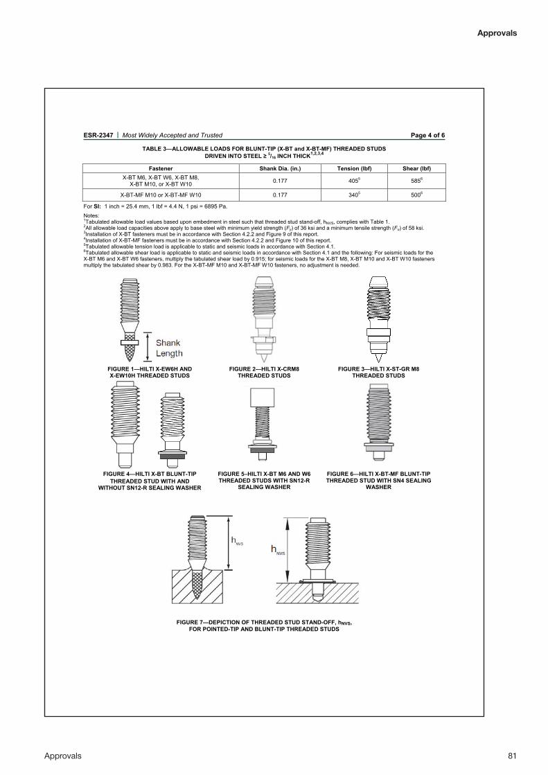
Approvals 81
Approvals
ESR-2347 | Most Widely Accepted and Trusted Page 4 of 6
TABLE 3—ALLOWABLE LOADS FOR BLUNT-TIP (X-BT and X-BT-MF) THREADED STUDS DRIVEN INTO STEEL ≥ 5/16 INCH THICK1,2,3,4
Fastener Shank Dia. (in.) Tension (lbf) Shear (lbf)X-BT M6, X-BT W6, X-BT M8,
X-BT M10, or X-BT W10 0.177 4055 5856
X-BT-MF M10 or X-BT-MF W10 0.177 3405 5006
For SI: 1 inch = 25.4 mm, 1 lbf = 4.4 N, 1 psi = 6895 Pa. Notes:1Tabulated allowable load values based upon embedment in steel such that threaded stud stand-off, hNVS, complies with Table 1.2All allowable load capacities above apply to base steel with minimum yield strength (Fy) of 36 ksi and a minimum tensile strength (Fu) of 58 ksi.3Installation of X-BT fasteners must be in accordance with Section 4.2.2 and Figure 9 of this report.4Installation of X-BT-MF fasteners must be in accordance with Section 4.2.2 and Figure 10 of this report.5Tabulated allowable tension load is applicable to static and seismic loads in accordance with Section 4.1.6Tabulated allowable shear load is applicable to static and seismic loads in accordance with Section 4.1 and the following: For seismic loads for the X-BT M6 and X-BT W6 fasteners, multiply the tabulated shear load by 0.915; for seismic loads for the X-BT M8, X-BT M10 and X-BT W10 fasteners multiply the tabulated shear by 0.983. For the X-BT-MF M10 and X-BT-MF W10 fasteners, no adjustment is needed.
FIGURE 1—HILTI X-EW6H AND X-EW10H THREADED STUDS
FIGURE 2—HILTI X-CRM8 THREADED STUDS
FIGURE 3—HILTI X-ST-GR M8 THREADED STUDS
FIGURE 4—HILTI X-BT BLUNT-TIP
THREADED STUD WITH AND WITHOUT SN12-R SEALING WASHER
FIGURE 5–HILTI X-BT M6 AND W6 THREADED STUDS WITH SN12-R
SEALING WASHER
FIGURE 6—HILTI X-BT-MF BLUNT-TIPTHREADED STUD WITH SN4 SEALING
WASHER
FIGURE 7—DEPICTION OF THREADED STUD STAND-OFF, hNVS,FOR POINTED-TIP AND BLUNT-TIP THREADED STUDS

82 Approvals
ESR-2347 | Most Widely Accepted and Trusted Page 5 of 6
Carbon steel studs Stainless steel pointed tip studs and X-BT blunt tip studs
X-BT-MF blunt tip studs
FIGURE 8—DEPICTION OF IDENTIFYING HEAD MARKINGS FOUND ON TOP OF THREADED STUDS
FIGURE 9—INSTALLATION INSTRUCTIONS FOR HILTI X-BT THREADED STUDS

Approvals 83
Approvals
ESR-2347 | Most Widely Accepted and Trusted Page 6 of 6
FIGURE 10—INSTALLATION INSTRUCTIONS FOR HILTI X-BT-MF THREADED STUDS

84 Approvals
Approvals
ICC-ES Evaluation Reports are not to be construed as representing aesthetics or any other attributes not specifically addressed, nor are they to be construed as an endorsement of the subject of the report or a recommendation for its use. There is no warranty by ICC Evaluation Service, LLC, express or implied, as to any finding or other matter in this report, or as to any product covered by the report.
Copyright © 2016 ICC Evaluation Service, LLC. All rights reserved. Page 1 of 1 1000
ICC-ES Evaluation Report ESR-2347 FBC SupplementReissued December 2015
Revised December 2016This report is subject to renewal December 2017.
www.icc-es.org | (800) 423-6587 | (562) 699-0543 A Subsidiary of the International Code Council®
DIVISION: 05 00 00—METALS Section: 05 05 23—Metal Fastenings
REPORT HOLDER:
HILTI, INC.7250 DALLAS PARKWAY, SUITE 100PLANO, TEXAS 75024(800) [email protected]
EVALUATION SUBJECT:
HILTI LOW-VELOCITY POWDER-ACTUATED DRIVEN THREADED STUDS FOR ATTACHMENT TO STEEL
1.0 REPORT PURPOSE AND SCOPEPurpose:The purpose of this evaluation report is to indicate that the Hilti Low-Velocity Powder-Actuated Driven Threaded Studs for Attachment to Steel, recognized in ICC-ES master evaluation report ESR-2347, have also been evaluated for compliance with the codes noted below.Applicable code editions: 2014 Florida Building Code—Building 2014 Florida Building Code—Residential
2.0 CONCLUSIONSThe Hilti Low-Velocity Powder-Actuated Driven Threaded Studs for Attachment to Steel, described in Sections 2.0 through 7.0 of the master report ESR-2347, comply with the 2014 Florida Building Code—Building and the 2014 Florida Building Code—Residential, provided the design and installation are in accordance with the 2012 International Building Code® (IBC) provisions noted in the master report, and the following conditions apply:
• Design wind loads must be based on Section 1609 of the 2014 Florida Building Code—Building or Section 301.2.1 of the 2014 Florida Building Code—Residential, as applicable.
• Load combinations must be in accordance with Section 1605.2 or Section 1605.3 of the 2014 Florida Building Code—Building, as applicable.
Use of the Hilti Low-Velocity Powder-Actuated Driven Threaded Studs for Attachment to Steel has also been found to be incompliance with the High-Velocity Hurricane Zone provisions of the 2014 Florida Building Code—Building and the 2014Florida Building Code—Residential under the following conditions:
• Use of the Hilti Low-Velocity Powder-Actuated Driven Threaded Studs for Attachment to Steel as a means of attachment of wood blocking, as defined in Section 2330.1.1 of the 2014 Florida Building Code—Building, in a roof assembly in the High-Velocity Hurricane Zone, is prohibited.
• Design wind loads must be based on Section 1620 of the 2014 Florida Building Code—Building, as applicable. For products falling under Florida Rule 9N-3, verification that the report holder’s quality-assurance program is audited by a
quality-assurance entity approved by the Florida Building Commission for the type of inspections being conducted is the responsibility of an approved validation entity (or the code official, when the report holder does not possess an approval by the Commission).
This supplement expires concurrently with the master report, reissued December 2015 and revised December 2016.

Customer testimonials 85
Customer testimonials
7. CUSTOMER TESTIMONIALS
“We use Hilti X-BT and grating fasteners to save time. The installation itself is much quicker (than alternative methods), in addition to this we save time by not damaging the coating.Hilti X-BT threaded stud is easy to use and has many applications.
We are using X-BT to fasten:• grating • sound reduction plates• fire extinguisher equipment• light cable supports• sign supports
These applications save us installation time. When the alternative is welding, the installation takes more time. One benefit is time and cost saving through avoiding coating damages.”
Bjørn HelleWork preparationsAker Soltuions, Norway
Comments from satisfied users
“After using the system we observed substantial gains in our efficiency. Our appli-cation is fixing cable trays to 10mm thick beams, normally our approach would have been to drill holes, which is time consuming and fix brackets with nuts, washers and bolts. With the X-BT (it is) one shot into the beam followed by fixing the bracket. A 2.5 meters long beam with 6 holes would normally take 2 hours to complete…with X BT it took 17 minutes on average!”
Joel CortejoE&I supervisor MIS Dubai
“Following our subsea activities on the yard of WARRI in Nigeria, I've recommended the use of your material XBT to avoid the painful rework (welding/painting, back and forth) for project USAN (TOTAL). Your material was also used for the winch of instal-lation of the risers of the TOTAL FPSO of MOHO BILONDO (direct line for TOTAL).”
Raymond GuillaumeChief EngineerAcergy, France

86 Notes
Notes 87
Notes
Hilti Corporation9494 Schaan, LiechtensteinP +423-234 0000
www.facebook.com/hiltigroup www.hilti.group H
ilti =
regi
ster
ed tr
adem
ark
of H
ilti C
orp.
, Sch
aan
W39
87 0
317
0-en
1
Prin
ted
in L
iech
tens
tein
©
201
7
Rig
ht o
f tec
hnic
al a
nd p
rogr
amm
e ch
ange
s re
serv
ed S
. E. &
O.