
Electricity from chemical reactions Galvanic Cells Chapter 14.
Upload
sybil-terryCategory
view
229download
0
WUT - MESC - Galvanic Cells II 1
Galvanic Cell
Galvanic Cells - INTRODUCTION
• Energy sources• How did the battery business start?• History of batteries makes history of electric energy
As ELECTROCHEMICAL DEVICE :Electrode reactions
Thermodynamics and kineticsProperties of Materials
As ENERGY SOURCE :Position on energy market
Power supplyTechnology & Economy
WUT - MESC - Galvanic Cells II 2
Electrical power generation
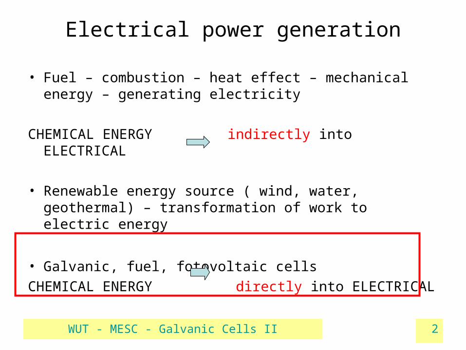
• Fuel – combustion – heat effect – mechanical energy – generating electricity
CHEMICAL ENERGY indirectly into ELECTRICAL
• Renewable energy source ( wind, water, geothermal) – transformation of work to electric energy
• Galvanic, fuel, fotovoltaic cells
CHEMICAL ENERGY directly into ELECTRICAL

WUT - MESC - Galvanic Cells II 3
DIFFERENT CELLS
• galvanic cells – primary and secondary
Chemical substances in electrodes
Expressed as Q
Electrode Reactions
Expressed as UEnergy = U . Q
• Fuel cells
Electrode Reactions
Expressed as U
Stream of reagents
Energy = U . Q
ISOLATED PORTABLE/TRANSPORTABLE
INDEPENDENT FORM ELECTROENERGETICAL NETWORK

WUT - MESC - Galvanic Cells II 4
Some milestones in history
1780 L. Galvani – „animal electricity”1800 A. Volta – pile (battery of zinc and silver discs, separated by cloth wet with salty solution)
1866 G. Leclanche – zinc – MnO2 cathode battery
1859 G. Plante’ – lead acid accu made of Pb plates,1881 – Faury et al – pasted plates instead of solid Pb
WUT - MESC - Galvanic Cells II 5
Transformation from isolated current sources to electrical network
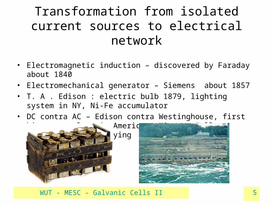
• Electromagnetic induction – discovered by Faraday about 1840• Electromechanical generator – Siemens about 1857• T. A . Edison : electric bulb 1879, lighting system in NY, Ni-Fe
accumulator • DC contra AC – Edison contra Westinghouse, first big power plant
in America – Niagara Falls – advantages of supplying energy with AC

WUT - MESC - Galvanic Cells II 6
Electrical circuits with batteries
• Management of voltage and current – connecting the batteries
• Ohm’s law in simple DC circuit : external resistance (load),internal resistance( ohmic drop on battery components), polarisation resistance (ohmic drop on reaction)
E = I ( Rinter + Rpol + Rload)
• Energy and power
Energy = Q ∙U = I ∙ t ∙ U = (m / k) ∙U
Power = energy produced/consumed in time unit
WUT - MESC - Galvanic Cells II 7
Electrode potential
• φ= φo + RT/nF ln ( aMe / aMe(n+) )
• Standard potential at unit activity of particles - φo
• + deviation from standard due to non-unit activity (concentration)• Can not be measured directly
Electrode reaction• Transport of charge or charge and mass over phase boundary electrode – electrolyte• Phases : electrode = fragment of condensed phase electronically conductive
electrolyte = ionically conducting „space”
Observed effects of electrode reaction :• Change of oxidation grade of an atom in a molecule / ion in solution• Accompanying changes : creation / decomposition of a phase
changes in phase structures
WUT - MESC - Galvanic Cells II 8
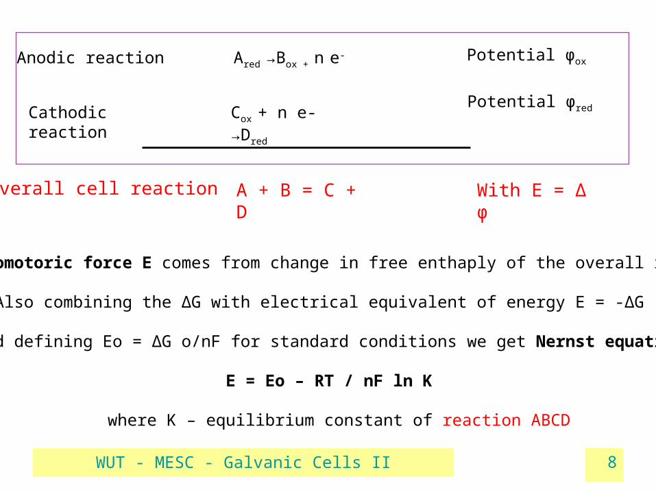
Ared →Box + n e-Anodic reaction
Cathodic reaction Cox + n e- →Dred
Potential φox
Potential φred
Overall cell reaction A + B = C + D With E = Δ φ
Electromotoric force E comes from change in free enthaply of the overall reaction,
Also combining the ΔG with electrical equivalent of energy E = -ΔG /nF
And defining Eo = ΔG o/nF for standard conditions we get Nernst equation :
E = Eo – RT / nF ln K
where K – equilibrium constant of reaction ABCD
WUT - MESC - Galvanic Cells II 9
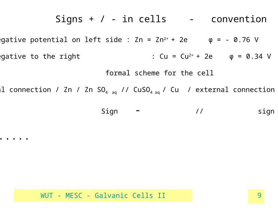
Signs + / - in cells - convention
More negative potential on left side : Zn = Zn2+ + 2e φ = - 0.76 V
Less negative to the right : Cu = Cu2+ + 2e φ = 0.34 V
formal scheme for the cell
External connection / Zn / Zn SO4 aq // CuSO4 aq / Cu / external connection
Sign - // sign +
But .....

WUT - MESC - Galvanic Cells II 10
Structure and functions of electrodes
A/ metallic reactive electrodes (deposition-dissolution, formation of compounds on the surface)
Reagent and current collector(two-in-one) Charge and mass transport – on the surface
B/ inert electrodesmetalls, graphite, semiconductors
Current collector, not a redox reagent Charge and mass transport – on the surface
C/ multi-function, multi-component electrodeselectroactive component (often insulator)electronically conducting matrixother additives with special functions
Charge and mass transport – on triple-contact sites Cond. matrix
Redox active
electrolyte

WUT - MESC - Galvanic Cells II 11
Various types of batteries

WUT - MESC - Galvanic Cells II 12
Specyfic energy - Energy density

WUT - MESC - Galvanic Cells II 13
Typical battery application

WUT - MESC - Galvanic Cells II 14

WUT - MESC - Galvanic Cells II 15
Zn/MnO2 Cells
• Leclanche type – electrolytes lightly acidic or neutral:
anodic reaction – product: Zn salts soluble in the electrolyte
( NH4Cl, NH4OH, ZnCl2 → complexes of Zn with OH- and Cl-
• Alkaline – electrolyte: concentrated KOH:
anodic reaction – product: solid ZnO – the composition ot the electrolyte does not change
• Different anodic mechanism → different yields of the cells :
in alkaline cells the maximum current density is higher
WUT - MESC - Galvanic Cells II 16
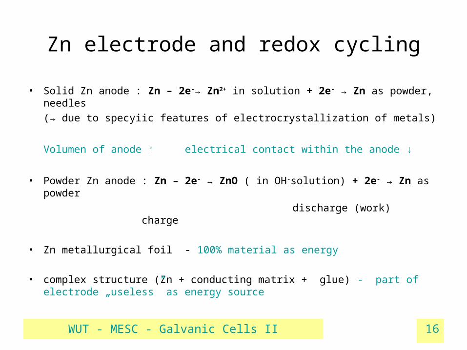
Zn electrode and redox cycling
• Solid Zn anode : Zn – 2e-→ Zn2+ in solution + 2e- → Zn as powder, needles
(→ due to specyiic features of electrocrystallization of metals)
Volumen of anode ↑ electrical contact within the anode ↓
• Powder Zn anode : Zn – 2e- → ZnO ( in OH-solution) + 2e- → Zn as powder
discharge (work) charge
• Zn metallurgical foil - 100% material as energy
• complex structure (Zn + conducting matrix + glue) - part of electrode „useless” as energy source
WUT - MESC - Galvanic Cells II 17
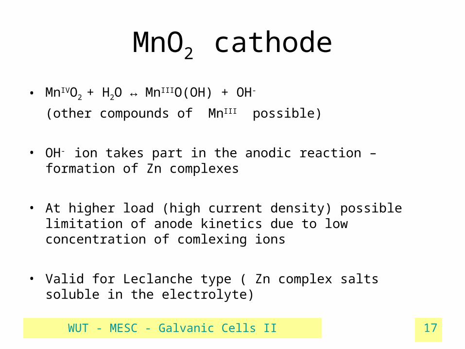
MnO2 cathode
• MnIVO2 + H2O ↔ MnIIIO(OH) + OH-
(other compounds of MnIII possible)
• OH- ion takes part in the anodic reaction – formation of Zn complexes
• At higher load (high current density) possible limitation of anode kinetics due to low concentration of comlexing ions
• Valid for Leclanche type ( Zn complex salts soluble in the electrolyte)

WUT - MESC - Galvanic Cells II 18
Cells with Zn anode
Cell name Cathode Electrolyte OCV or EMF (V)
Daniell Cu → Cu2+ ZnSO4/CuSO4 1.2 Anode product – soluble Zn saltsLeclanche MnO2→MnO(OH)
(→Mn3O4 possible)
NH4Cl, ZnCl2 1.6
Alkali MnO2→MnO(OH) KOH 1.55 Anode product - ZnO
Zinc-air O2 → O2- (on carbon matrix)
KOH 1.45
Zinc-silver Ag2O → Ag KOH 1.6

WUT - MESC - Galvanic Cells II 19
Zn - air• A : Zn → Zn2+ (as ZnO) + 4e-
• C : O2 + 2 H2O + 4e- → 4 OH- EMF = 1.65 V
• Cathode reaction on inert catalytic electrode ( graphite + catalyst + binder)• Oxygen supply forced by underpressure in cathode space • Slow kinetics of oxygen electrode – main limitation for current value
• Parasitic processes : Zn + O2
OH- + CO2
loss of water

WUT - MESC - Galvanic Cells II 20
Electric vehicles• „zero-emission” buses and vans on tests in USA and Germany
• Repleceable anodic casette of Zn with KOH (gelled)
• Ca. 200 Wh/kg and 90 W/kg at 80% d.o.c.
• Supercapacitor in hybrid system to boost accelaration
• External regeneration of anodes

WUT - MESC - Galvanic Cells II 21
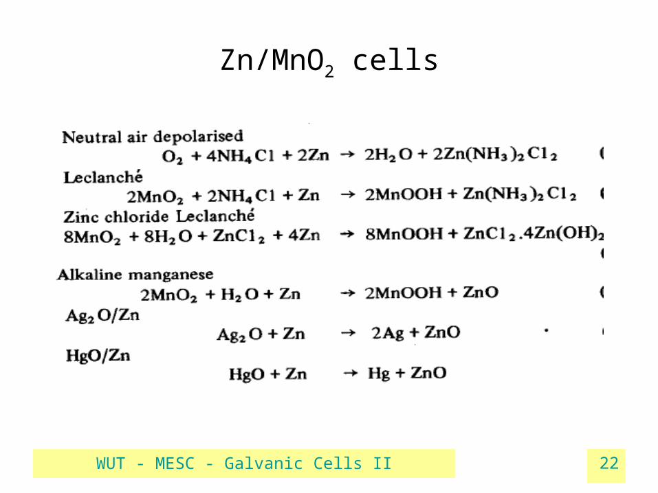
Zn/MnO2 cells
WUT - MESC - Galvanic Cells II 22
Zn/MnO2 cells

WUT - MESC - Galvanic Cells II 23
How to get „more” from a single cell?
• Redox potential for Me – Men+ couples
• Apply special conditions of discharge
• Eliminate water from cells
Zn-Zn2+ -0.76 V O2-OH- 0.4 V
Mg-Mg2+ -2.36 V Ag+-Ag 0.8 V
Na-Na2+ -2.92 V MnO2-MnO(OH) app. 0.74 V
Li-Li+ -3.05 V F2 – 2F- 2.87 V
non-aqueous solutions
synthesis in inert atmosphere
Reserve cells
one-time discharge
WUT - MESC - Galvanic Cells II 24
Reserve (activated) cells
• Separated elements –
• Signal to make contact electrolyte – electrodes : closing the circuit inside the cell
• Activation on signal (decision) or by event (water flow, emergency)
• No or poor activity if energy demand intermittent
• Very long storage time (no parasitic reactions and self-discharge)
• Energy supply – short time, but high current densities
dry electrodes
inactive electrolyte :
-closed in a vessel
-solid salt to be molten
WUT - MESC - Galvanic Cells II 25
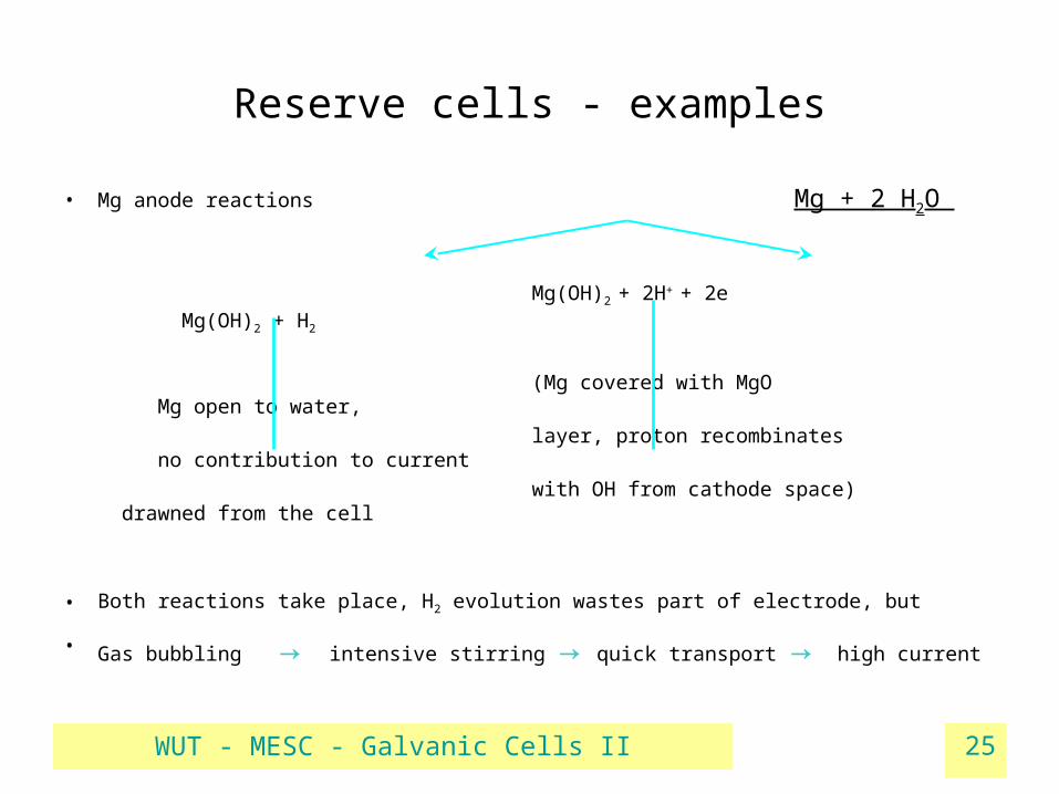
Reserve cells - examples
• Mg anode reactions Mg + 2 H2O
Mg(OH)2 + 2H+ + 2e Mg(OH)2 + H2
(Mg covered with MgO Mg open to water,
layer, proton recombinates no contribution to current
with OH from cathode space) drawned from the cell
• Both reactions take place, H2 evolution wastes part of electrode, but
• Gas bubbling → intensive stirring → quick transport → high current
WUT - MESC - Galvanic Cells II 26
Reserve cells – examples cont.
• Cathodes in Mg cells :
• 2 AgCl + 2e → Ag + 2 Cl-
• 2 CuCl + 2e → Cu + 2 Cl-
• other simple salts : PbCl2 , CuSCN, Cu2I2
• Overall reaction : Mg + PbCl2 = MgCl2 + Pb
• Electrolytes : sea-water, simple salts specific for best cathode rate
• construction: composite cathodes, mechanical separation of electrodes, soakable separators for electrolyte
WUT - MESC - Galvanic Cells II 27
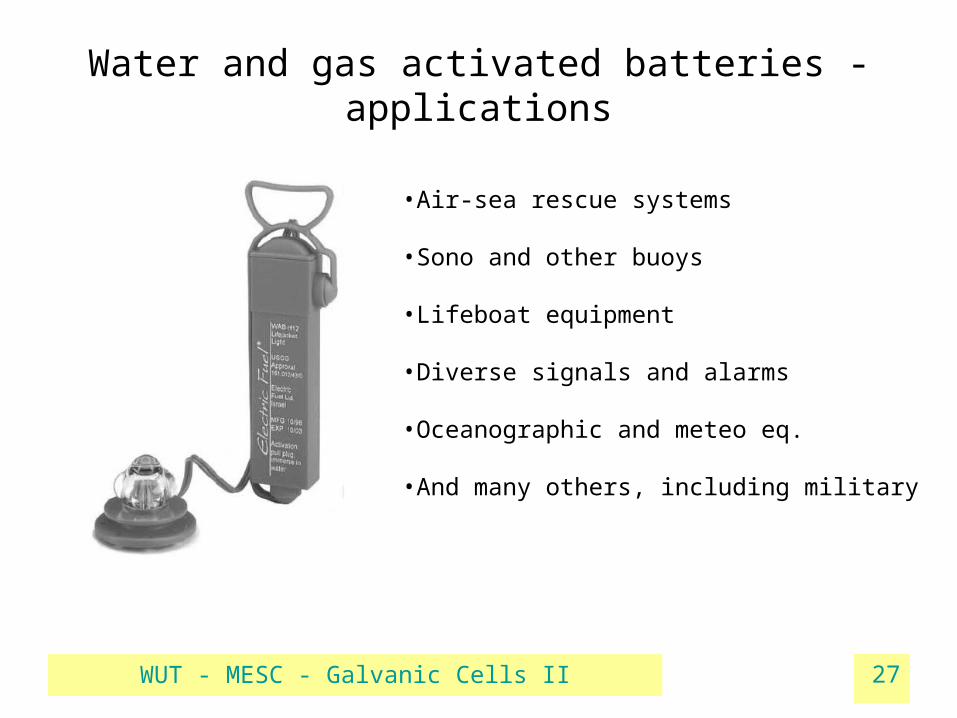
Water and gas activated batteries - applications
•Air-sea rescue systems
•Sono and other buoys
•Lifeboat equipment
•Diverse signals and alarms
•Oceanographic and meteo eq.
•And many others, including military
WUT - MESC - Galvanic Cells II 28
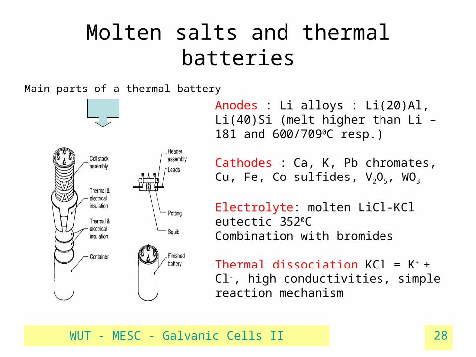
Molten salts and thermal batteries
Main parts of a thermal battery
Anodes : Li alloys : Li(20)Al, Li(40)Si (melt higher than Li – 181 and 600/7090C resp.)
Cathodes : Ca, K, Pb chromates, Cu, Fe, Co sulfides, V2O5, WO3
Electrolyte: molten LiCl-KCl eutectic 3520CCombination with bromides
Thermal dissociation KCl = K+ + Cl-, high conductivities, simple reaction mechanism

WUT - MESC - Galvanic Cells II 29
Thermal batteries – applications
• Pyrotechnic heat source – squib, burned serves as inter-cell conductor
• Insulation – ceramic, glass, polymers – depends on time of discharge
(salt must be kept molten !)
• Voltages – single OCV : 1.6 V (Li/FeS2) , to ca. 3 V (Ca/K2Cr2O7)
• Activated life-time : minutes, in special constructions hours
• Energy density : 2 – 35 Wh/kg
• High currents possible
• Applications – mainly military

WUT - MESC - Galvanic Cells II 30
Solid electrolyte cell Na-S
Anode Na → Na+
Cathode xS → Sx2- , x 3~5
Overall 2Na + xS → Na2Sx
OCV = 2.07 V
Temperature 310 – 350oC
sulphur Tmelt = 118, boil= 444oC
β-alumina Na2O∙11Al2O3 , conducts Na ions σ300 C ca 0.5-0.1 S/cm

WUT - MESC - Galvanic Cells II 31
Solid electrolyte cell Na-S
• Can be used as rechargeable cell
• Applications : stationary energy storage, motive power
• Working with high-temperature cells:
warm-up on start
keep warm at intervals in operation
manage excessive heat during operation (ohmic and reaction)
• Construction of stacks : electrical and heat management
Insulated enclosure Cooling system
Heat distribution heatersElectricalnetworking
WUT - MESC - Galvanic Cells II 32
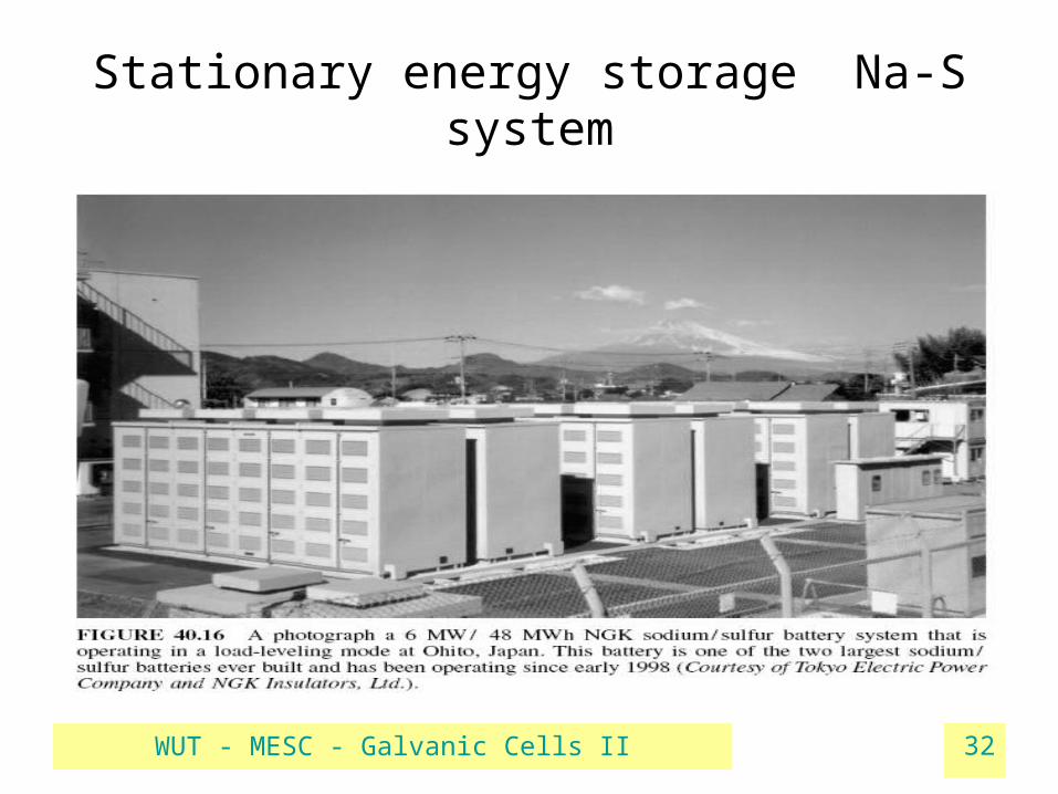
Stationary energy storage Na-S system

WUT - MESC - Galvanic Cells II 33
Lithium – iodine solid electrolyte cell
• Anode : Li → Li+ + 2e
• Cathode : nI2∙P2VP + 2e → (n-1)I2P2VP + 2 I- (poly-2-vinylpyridine)
• Overall : 2Li + I2 → 2 LiI
• LiI thin layer on contact between Li and cathode, ionically conducting
• OCV ca 2.8 V• Discharge rates 1 – 2 μA/cm2 (very low)
WUT - MESC - Galvanic Cells II 34
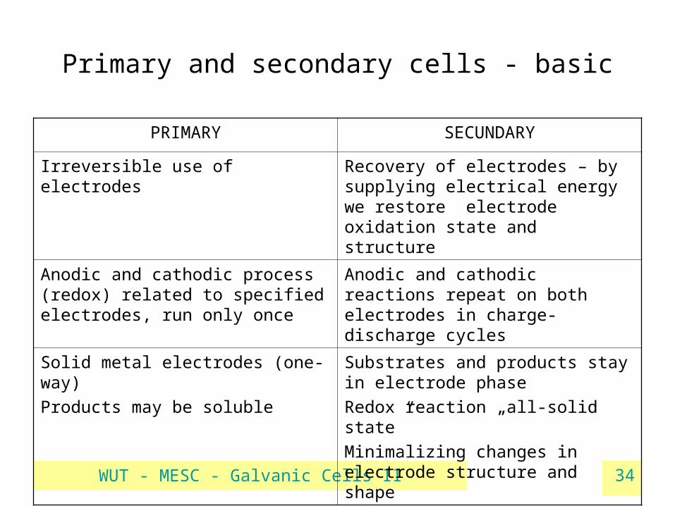
Primary and secondary cells - basic
PRIMARY SECUNDARY
Irreversible use of electrodes Recovery of electrodes – by supplying electrical energy we restore electrode oxidation state and structure
Anodic and cathodic process (redox) related to specified electrodes, run only once
Anodic and cathodic reactions repeat on both electrodes in charge-discharge cycles
Solid metal electrodes (one-way)
Products may be soluble
Substrates and products stay in electrode phase
Redox reaction „all-solid state”
Minimalizing changes in electrode structure and shape
WUT - MESC - Galvanic Cells II 35
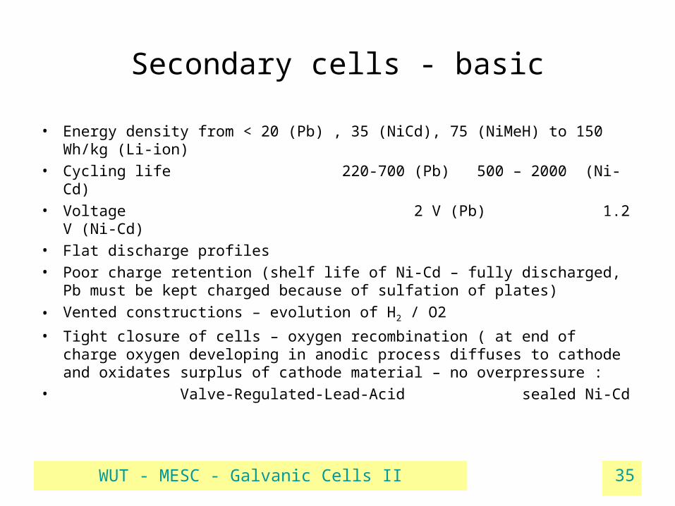
Secondary cells - basic
• Energy density from < 20 (Pb) , 35 (NiCd), 75 (NiMeH) to 150 Wh/kg (Li-ion)
• Cycling life 220-700 (Pb) 500 – 2000 (Ni-Cd)
• Voltage 2 V (Pb) 1.2 V (Ni-Cd)
• Flat discharge profiles
• Poor charge retention (shelf life of Ni-Cd – fully discharged, Pb must be kept charged because of sulfation of plates)
• Vented constructions – evolution of H2 / O2
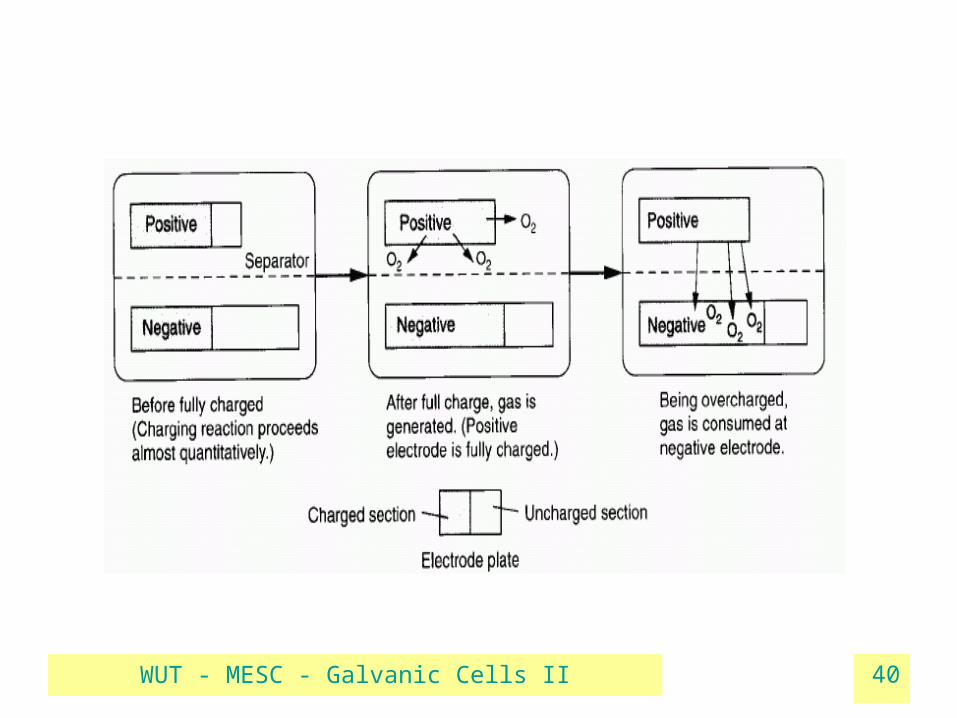
• Tight closure of cells – oxygen recombination ( at end of charge oxygen developing in anodic process diffuses to cathode and oxidates surplus of cathode material – no overpressure :
• Valve-Regulated-Lead-Acid sealed Ni-Cd
WUT - MESC - Galvanic Cells II 36
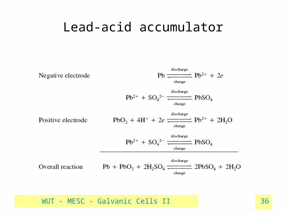
Lead-acid accumulator

WUT - MESC - Galvanic Cells II 37
cycle „negative mass” „positive mass”
discharge
Pb → PbSO4 (oxidation)
Concentration of H2SO4 ↓
PbO2 → PbSO4 (reduction)
Concentration of H2SO4 ↓
charge
PbSO4 → Pb (reduction)
Concentration of H2SO4 ↑
PbSO4 → PbO2 (oxidation)
Concentration of H2SO4 ↑

WUT - MESC - Galvanic Cells II 38
Phenomena in discharge cycle
• CH2SO4 • PbSO4 – insulator ( ca. 1010 Ώcm)• Vmol PbSO4 > Vmol Pb, PbO2
worse porosity diffusion of the electrolyte into the structure impaired
R int What happens with: current density at U = const ?Voltage at I = const. ?

WUT - MESC - Galvanic Cells II 39
WUT - MESC - Galvanic Cells II 40

WUT - MESC - Galvanic Cells II 41
Alkaline accumulators
• Ni –Cd , Ni – Fe, Ni – MeH ( 1.2V)Ag – Zn ( 1.5V)
Ni – Zn (1.6V)• Cathode Ni
NiIII OOH + H20 + e- Ni(OH)2 + OH-
• Anode Cd
Cd + 2(OH-) Cd(OH)2 + 2e-
• Ag-Zn : Ag2O + H2O + 2e 2Ag + 2 OH-
Zn + 2(OH-) Zn(OH)2 + 2e

WUT - MESC - Galvanic Cells II 42
Ni-Cd accumulator
cycle „masa ujemna” „masa dodatnia”
discharge
Cd → Cd(OH)2
(oxidation)NiOOH → Ni(OH)2 (reduction)
charge
Cd(OH)2 → (reduction) Ni II(OH)2 → Ni IIIOOH (oxidation)

WUT - MESC - Galvanic Cells II 43
(further electrolysis after charging effects in evolution of O2)
((further electrolysis after charging effects in evolution of H2)

WUT - MESC - Galvanic Cells II 44
Oxygen and hydrogen formation in cells• Reactions possible in water solution
• Equilibrium potentials : E (H+/H2) = 0V , E (OH-/O2) = 0.4 V
• BUT – overpotentials due to phenomena at gas-solid electrode phase boundary make true potentials higher
• For different metals the hydrogen evolution potential grows from:Pt - Ni - Ag - Zn - Cd - Pb (and compounds)
• Still, at the end of charge/discharge cycle co-evolution of gases in
cells occurs• In effect: overpressure inside the cell, - H2 i O2
• „oxygen recombination” – electrodes not equivalent in charge, ex. QCd > QNi

WUT - MESC - Galvanic Cells II 45
Basic secondary cells
Ni-Cd
•Pocket electrode construction of electrodes•Sintered plates
Pb acid
•Pasted plates•Tubular positive plates•Plante’ design

WUT - MESC - Galvanic Cells II 46
Technology of electrode masses in Ni-Cd
• Electrodes prepared in discharged state : Ni(OH)2 and Cd(OH)2 as
• Additives: graphite ,”-” mass – Fe+ Ni (→ Cd crystallization)
• Formation of plates : several charge-discharge cycles
• Assembly and hermetic closure
• Separators – ionic conductivity and oxygen diffusion (thickness ca0.2 mm)
• For O2 recombination higher capacity of „-” mass (Cd) – fully charged Ni mass – O2evolution – diffusion – Cd oxidised to CdO, no possiblity of H2 formation
Compresed powderNiSO4→Ni(OH)2
CdSO4 →Cd(OH)2
Encapsulated in steel/Ni pocket
Sintered platePorous Ni plate
Impregnated with Ni , Cd saltsTransformed to hydroxides „in situ”
WUT - MESC - Galvanic Cells II 47
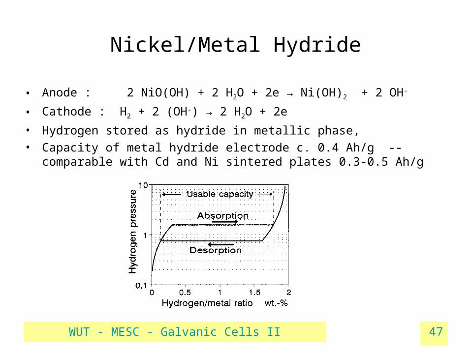
Nickel/Metal Hydride
• Anode : 2 NiO(OH) + 2 H2O + 2e → Ni(OH)2 + 2 OH-
• Cathode : H2 + 2 (OH-) → 2 H2O + 2e
• Hydrogen stored as hydride in metallic phase,
• Capacity of metal hydride electrode c. 0.4 Ah/g -- comparable with Cd and Ni sintered plates 0.3-0.5 Ah/g
WUT - MESC - Galvanic Cells II 48
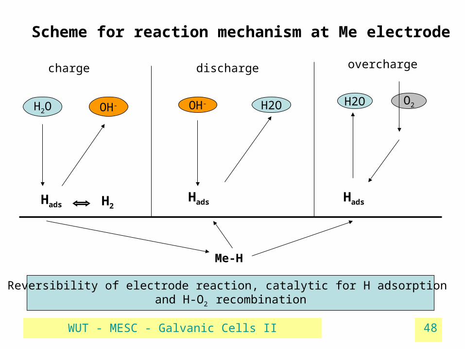
Scheme for reaction mechanism at Me electrode
charge discharge overcharge
Me-H
H2O OH- OH- H2O H2O O2
Hads H2Hads Hads
Reversibility of electrode reaction, catalytic for H adsorption and H-O2 recombination

WUT - MESC - Galvanic Cells II 49
Hydrogen absorbing alloys
• A – metal forming stable hydrides
• B – weak hydrides, catalyst, resistance to corrosion, control Hads pressure
Class (basis) Components Storage Ah/kg Remarks
AB5
(LaNi5)
A: Mischmetall, La, Ce, Ti
B: Ni, Co, Mn, Al
≈ 300 Mostly used
AB2
(TiNi2)
A: Zr, Ti
B: Ni, Fe, Cr, V
≈ 400 „Ovonic” alloys
• Nickel - catalyst for H2 dissociation,, regulator for Zr, Ti, V hydride formation,

WUT - MESC - Galvanic Cells II 50
Some details on production of alloys
• Ni mass – traditional, new technologies for MeH electrode powder
• Ovonic alloy – example : main components : Zr-Ti-V-Ni + Cr, Mn, Co, Fe...
• Preparative technics: electric arc or inductive oven, Ar atmosphere
• Production of powder : hydrogenation of cast alloy (volume expansion = crushing of a piece), followed by mechanical pulverisation
• Sintered plates : MeH powder + Ni, Ni(CO)5 + resin →
pressing and sintering under vacuum

WUT - MESC - Galvanic Cells II 51
Lithium cells
Atomic mass LITHIUM ZINC
Standard potential (V) -3.05 -0.76
Melting point (oC) 181 419
Density (kg/m3) 534 7100
Elchem. equivalent (Ah/g) 3.86 0.82
•Reactivity of metallic lithium: reduces most substances (even Teflon®)•Stable passivation – key to electrode stability•What shall we do with excess lithium? •Transport and consume in cathode reaction•Why not leave lithium cations in the electrolyte?
Anodic reaction : Li = Li+ + 1e

WUT - MESC - Galvanic Cells II 52
Anode
Metallic Li (foil) Intercalation : Li – Li+ in matrix
Stable passivation layer on discharge
Charge : mossy, dendritic deposit – corrosion of fresh Li
internal shortcutting
Main application – primary cells
Rechargeable –
attempts with polymer electrolytes
Capacity: 3.86Ah/g, in accu < 1 Ah/g
Carbon materials : coke, graphite etc.
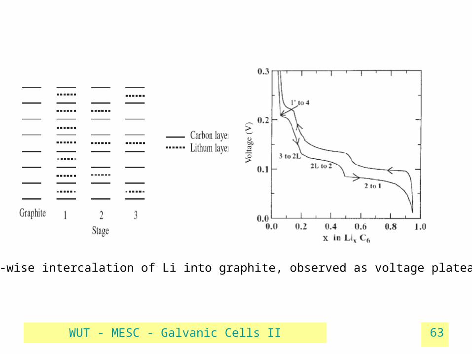
6 – 12 C atoms take 1 lithium atom into the structure
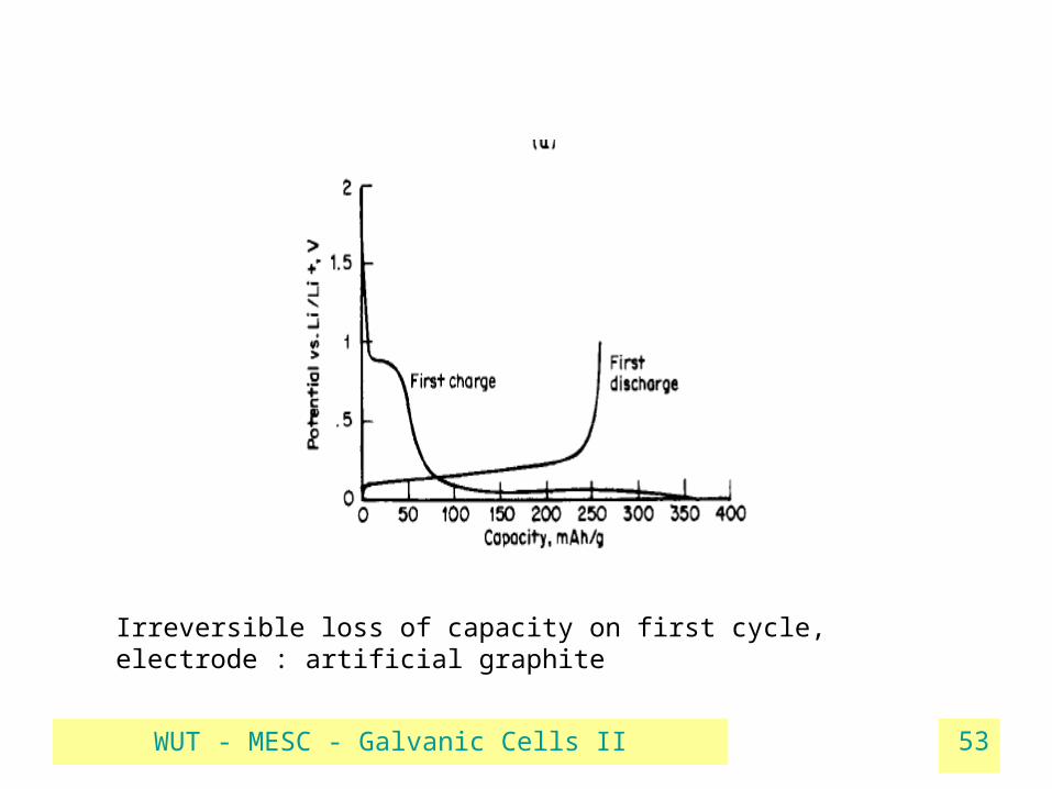
First cycle – formation of SEI
(Solis Electrolyte Interface)
portion of Li used for reaction with electrolyte
Some transition metal compounds
Capacity: 0.372 Ah/g
WUT - MESC - Galvanic Cells II 53
Irreversible loss of capacity on first cycle, electrode : artificial graphite
WUT - MESC - Galvanic Cells II 54

WUT - MESC - Galvanic Cells II 55
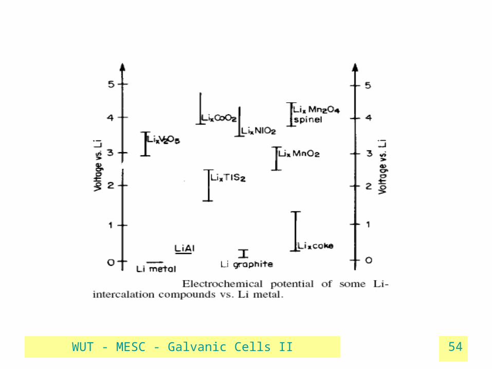
Cathodes• Redox potentials in 0 – 1 V range - OCV of Li cells from 3 to 4 V
Solid: MexOy
Reduction of Me ion to lower oxidation state, like MnIVO2 – MnIIIO2
Topotactic reaction
Insertion of Li+ into host structure
Some other: V2O5, (CF)n, TiS2
Capacities: 0.31(MnO2), 0.86(CF) Ah/g
Soluble
SO2 + 2e → S2O42-
( in solution, + Lisalt ex. LiAlCl4)
Thionyl chloride:
SOCl2 + 4e → S + SO2
Sulfuryl chloride:
SO2Cl2 + 2e → SO2
(solvents for Li salt)
Capacities : ≈ 0.4 Ah/g

WUT - MESC - Galvanic Cells II 56

WUT - MESC - Galvanic Cells II 57
Layered structure of LiCoO2
Carbon layers in regular graphite

WUT - MESC - Galvanic Cells II 58
Electrolytes
Conductivity, Li+ transference number
Electrochemical and thermal stability
Liquid organic•Aprotic•Protective passivation layer on Li•Li salts solute and dissociate•Appropiate physical features: stable non-toxic, nonflammable •Conductivities ≈ 1e-3 S/cm
Polymer Li conduction via
coordination sites on polymer chains(ex. Poly(ethylenoxide)Solid foils, processableMore stable against Li
Conductivities : 1e-7 –1e-4 S/cm
Gel2 in 1 : polymer matrix immobilizing liquid electrolyte

WUT - MESC - Galvanic Cells II 59
Solution Ionic conductivity (20oC) S/cm
1M H2SO4 10-1
Nafion® foil (H+) 10-2
1M LiBF4 in acetonitrile 10-3
PEO-LiClO4 complex 10-6

WUT - MESC - Galvanic Cells II 60
WUT - MESC - Galvanic Cells II 61

WUT - MESC - Galvanic Cells II 62
WUT - MESC - Galvanic Cells II 63
Step-wise intercalation of Li into graphite, observed as voltage plateaux

WUT - MESC - Galvanic Cells II 64
Parameters and definitions
• EMF or OCV• nominal voltage (accepted as typical for a certain battery)• End (cut-off) voltage • Theoretical capacity : comes from amount of active materials• Rated capacity • Energy density (Watthour/l) and specyfic energy (Watthour/kg) :
theoretical E = Q × EMF, practical E = Q×ΔU• Power density• Shelf life
WUT - MESC - Galvanic Cells II 65
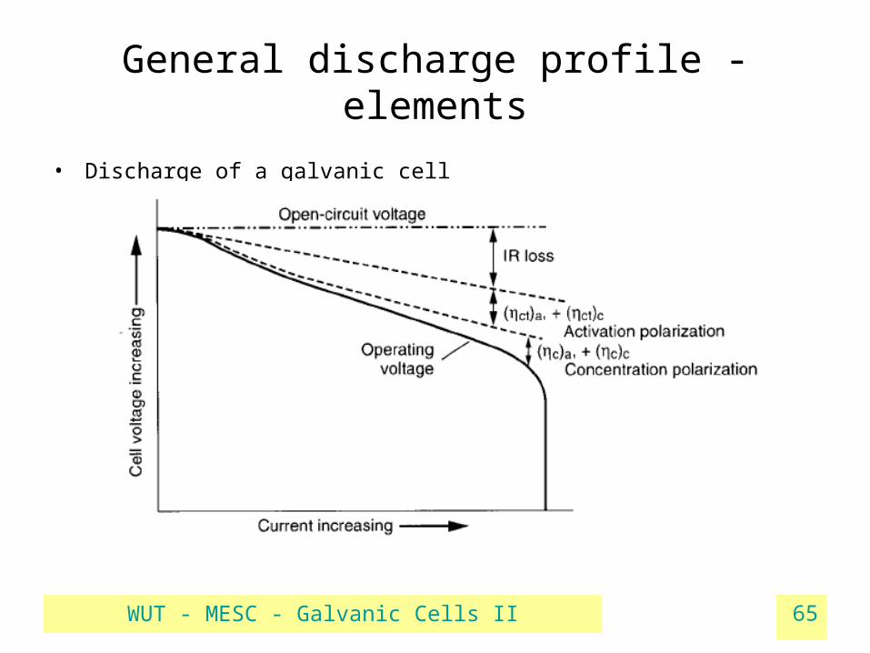
General discharge profile - elements
• Discharge of a galvanic cell

WUT - MESC - Galvanic Cells II 66
C - rate
• Charge / discharge current of a battery, given as
I (amper) = Cn (amperhours) . M (multiply or fraction of C)
!!! Traditional convention, but units are uncorrect!!!
However, most producers and studies use this measure !!!
• Ex. For a 250 mAh rated battery (declaration of producer) :
1C – rate = 250 mA
0.1C –rate = 25 mA and so on
• We can compare batteries at equal C-rates or study discharge for a given battery at different C-rates
WUT - MESC - Galvanic Cells II 67
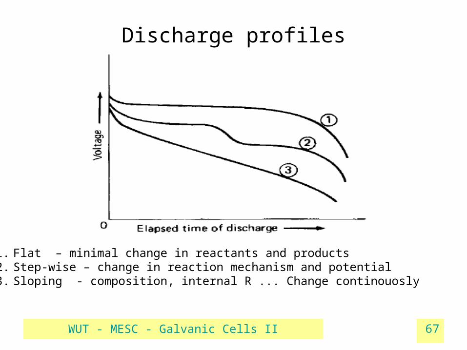
Discharge profiles
1. Flat – minimal change in reactants and products2. Step-wise – change in reaction mechanism and potential3. Sloping - composition, internal R ... Change continouosly

WUT - MESC - Galvanic Cells II 68
WUT - MESC - Galvanic Cells II 69
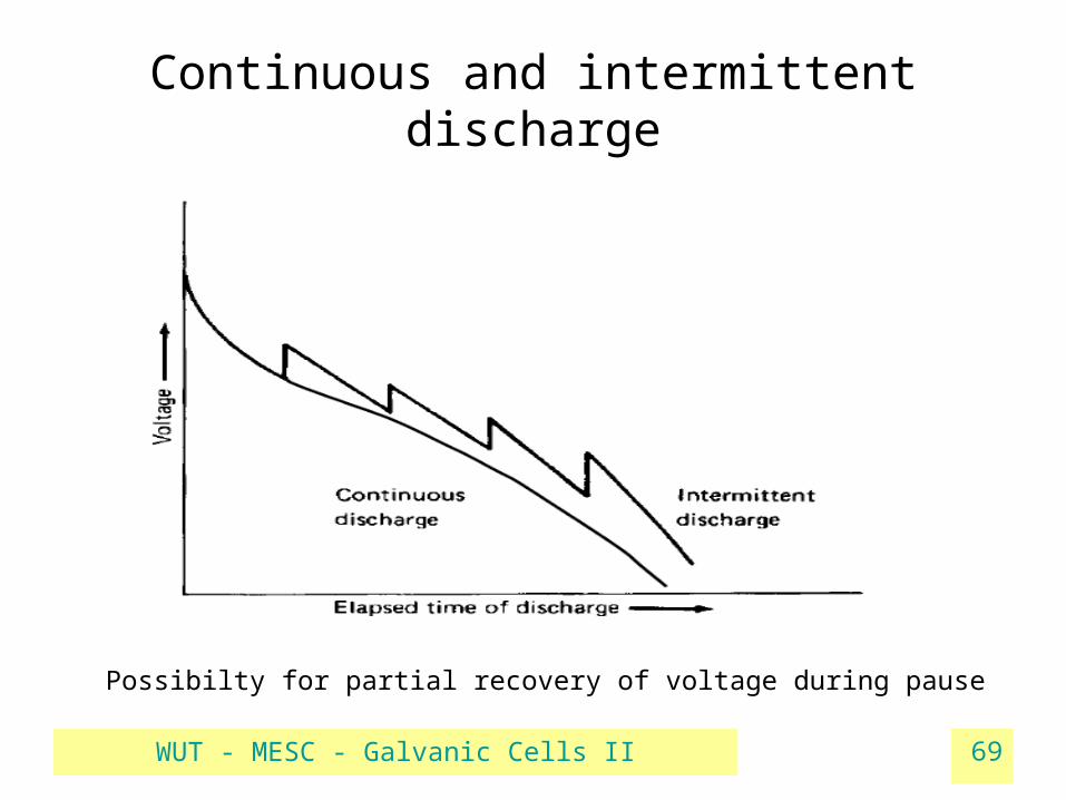
Continuous and intermittent discharge
Possibilty for partial recovery of voltage during pause
WUT - MESC - Galvanic Cells II 70
Discharge
• Discharge mode – constant current / resistance / power
(time to reach cut-off U may differ)• Electrode design = f (type of service)• Max. quantity of active material = max. energy supply• Max. electrode surface = high discharge rate (current, power) • Possibility of partial restoration of voltage – stand-by intervals

WUT - MESC - Galvanic Cells II 71


