WTRPO Facility – HVAC and Civil Work TESTING, ADJUSTING ... · WPG/462784 Testing, Adjusting and...
27
WTRPO Facility – HVAC and Civil Work Bid Opportunity No. 85-2015 WPG/462784 Testing, Adjusting and Balancing of HVAC 27 Jan 2015 - Rev. A 23 05 93 - 1 SECTION 23 05 93 TESTING, ADJUSTING AND BALANCING OF HVAC PART 1 GENERAL 1.1 SCOPE OF WORK A. The Contractor will contract with an independent Testing, Adjusting and Balancing (TAB) agency to test, adjust and balance the HVAC systems. B. The work included in this section consists of furnishing labor, instruments, and tools required in testing, adjusting and balancing the HVAC systems, as described in these specifications or shown on accompanying drawings. Services shall include checking equipment performance, taking the specified measurements, and recording and reporting the results. C. The items requiring testing, adjusting and balancing include the following: 1. EF-X606, Acid exhaust air fan and associated ductwork; 2. EF-X607, Caustic Soda exhaust air fan and associated ductwork; 3. EF-X608, Hydrogen Peroxide exhaust air fan and associated ductwork; 4. EF-X609, Ozone Generator exhaust air fan and associated ductwork. 5. FH-X610, Fume hood and associated ductwork; 6. EF-H013, Existing Pilot Plant room exhaust air fan and associated ductwork. 1.2 DEFINITIONS, REFERENCES, STANDARDS A. All work shall be in accordance with the most strigent requirements of these contract documents, the latest edition of the AABC National Standards and ASHRAE standards. 1.3 QUALIFICATION A. Agency Qualifications: The TAB Agency shall be a current member of AABC. 1.4 SUBMITTALS A. Qualifications: The TAB agency shall submit a company resume listing personnel and project experience in air system balancing. B. Procedures and Agenda: The TAB agency shall submit the TAB procedures and agenda proposed to be used. C. Sample Forms: The TAB agency shall submit sample forms, which shall include the minimum data required by the AABC National Standards.
Transcript of WTRPO Facility – HVAC and Civil Work TESTING, ADJUSTING ... · WPG/462784 Testing, Adjusting and...
WTRPO Facility – HVAC and Civil Work Bid Opportunity No. 85-2015
WPG/462784 Testing, Adjusting and Balancing of HVAC 27 Jan 2015 - Rev. A 23 05 93 - 1
SECTION 23 05 93
TESTING, ADJUSTING AND BALANCING OF HVAC
PART 1 GENERAL
1.1 SCOPE OF WORK
A. The Contractor will contract with an independent Testing, Adjusting and Balancing (TAB) agency to test, adjust and balance the HVAC systems.
B. The work included in this section consists of furnishing labor, instruments, and tools required in testing, adjusting and balancing the HVAC systems, as described in these specifications or shown on accompanying drawings. Services shall include checking equipment performance, taking the specified measurements, and recording and reporting the results.
C. The items requiring testing, adjusting and balancing include the following: 1. EF-X606, Acid exhaust air fan and associated ductwork; 2. EF-X607, Caustic Soda exhaust air fan and associated ductwork; 3. EF-X608, Hydrogen Peroxide exhaust air fan and associated ductwork; 4. EF-X609, Ozone Generator exhaust air fan and associated ductwork. 5. FH-X610, Fume hood and associated ductwork; 6. EF-H013, Existing Pilot Plant room exhaust air fan and associated ductwork.
1.2 DEFINITIONS, REFERENCES, STANDARDS
A. All work shall be in accordance with the most strigent requirements of these contract documents, the latest edition of the AABC National Standards and ASHRAE standards.
1.3 QUALIFICATION
A. Agency Qualifications: The TAB Agency shall be a current member of AABC.
1.4 SUBMITTALS
A. Qualifications: The TAB agency shall submit a company resume listing personnel and project experience in air system balancing.
B. Procedures and Agenda: The TAB agency shall submit the TAB procedures and agenda proposed to be used.
C. Sample Forms: The TAB agency shall submit sample forms, which shall include the minimum data required by the AABC National Standards.
WTRPO Facility – HVAC and Civil Work Bid Opportunity No. 85-2015
WPG/462784 Testing, Adjusting and Balancing of HVAC 27 Jan 2015 - Rev. A 23 05 93 - 2
1.5 TAB PREPARATION AND COORDINATION
A. Shop drawings, submittal data, up-to-date revisions, change orders, and other data required for planning, preparation, and execution of the TAB work shall be provided to the TAB agency no later than 30 days prior to the start of TAB work.
B. System installation and equipment startup shall be complete prior to the TAB agency's being notified to begin.
C. All test points, balancing devices, identification tags, etc. shall be accessible and clear of insulation and other obstructions that would impede TAB procedures.
D. Qualified installation or startup personnel shall be readily available for the operation and adjustment of the systems. Assistance shall be provided as required for coordination and problem resolution.
1.6 REPORTS
A. Final TAB Report - The TAB agency shall submit the final TAB report for review to the Contract Administrator. All outlets, devices, HVAC equipment, etc., shall be identified, along with a numbering system corresponding to report unit identification. The TAB agency shall submit an AABC "National Project Performance Guaranty" assuring that the project systems were tested, adjusted and balanced in accordance with the project specifications and AABC National Standards.
1.7 DEFICIENCIES
A. Any deficiencies in the installation or performance of a system or component observed by the TAB agency shall be brought to the attention of the Contract Administrator.
B. The work necessary to correct items on the deficiency listing shall be performed and verified by the Contractor before the TAB agency returns to retest. Unresolved deficiencies shall be noted in the final report.
PART 2 PRODUCTS
2.1 INSTRUMENTATION
A. All instruments used for measurements shall be accurate and calibrated. Calibration and maintenance of all instruments shall be in accordance with the requirements of AABC National Standards.
WTRPO Facility – HVAC and Civil Work Bid Opportunity No. 85-2015
WPG/462784 Testing, Adjusting and Balancing of HVAC 27 Jan 2015 - Rev. A 23 05 93 - 3
PART 3 EXECUTION
3.1 GENERAL
A. The specified systems shall be reviewed and inspected for conformance to design documents. Testing, adjusting and balancing on each identified system shall be performed. The accuracy of measurements shall be in accordance with AABC National Standards. Adjustment tolerances shall be + or - 10% unless Otherwise stated.
B. Equipment settings, including manual damper quadrant positions, manual valve indicators, fan speed control levers, and similar controls and devices shall be marked to show final settings.
C. All information necessary to complete a proper TAB project and report shall be per AABC standards unless otherwise noted. The descriptions for work required, as listed in this section, are a guide to the minimum information needed.
3.2 PRECONSTRUCTION PLAN CHECK AND REVIEW
A. The TAB agency shall review the project documents and contractor submittals for their effect on the TAB process and overall performance of the HVAC system. It shall submit recommendations for enhancements or changes to the system within 30 days of document review to the Contact Administrator.
3.3 TAB REPORT VERIFICATION
A. At the time of final inspection, the TAB agency may be required to recheck, in the presence of the Contract Administrator specific or random selections of data recorded in the certified report. Points and areas for recheck shall be selected by the Contract Administrator. Measurements and test procedures shall be the same as approved for the initial work for the certified report. Selections for recheck, specific plus random, will not exceed 30% of the total number tabulated in the report.
3.4 AIR SYSTEMS
A. The TAB agency shall verify that all ductwork, dampers, grilles, registers, and diffusers have been installed per design and set in the full open position. The TAB agency shall perform the following TAB procedures in accordance with the ASHRAE guidelines or AABC National Standards: 1. For chemical exhaust fans:
a. Fan speeds - Test and adjust fan RPM to achieve maximum or design airflow.
b. Current and Voltage - Test and record motor voltage and amperage, and compare data with the nameplate limits to ensure motor is not in or above the service factor.
c. Pitot-Tube Traverse - Perform a Pitot-tube traverse of main exhaust ducts to obtain total airflow.
d. Static Pressure - Test and record system static profile of each exhaust fan.
WTRPO Facility – HVAC and Civil Work Bid Opportunity No. 85-2015
WPG/462784 Testing, Adjusting and Balancing of HVAC 27 Jan 2015 - Rev. A 23 05 93 - 4
2. For zone, branch and main ducts: a. Adjust ducts to within design airflow requirements. As applicable, at
least one zone balancing damper shall be completely open. Multi-inlet/outlet branch ducts shall have at least one outlet or inlet volume damper completely open.
3. For EF- H013 a. Reduce exhaust air into to the four (4) exhaust registers WR-700x350 at
the mezzanine level of the Pilot Plant Room from 613 l/s to 530 l/s. b. Reduce exhaust air flow to the two (2) exhaust registers WR-250 x 150
in the Pilot Plant Lab from 94 l/s to 20 l/s each. c. Change sheaves and belt on EF-H013 if required.
3.5 FUME HOOD TESTING (FH-X610)
A. The TAB agency shall test and adjust fume hood total air flow by duct Pitot-tube traverse. If a Pitot-tube traverse is not practical, an explanation of why a traverse was not made must appear on the appropriate data sheet. Test and record face velocities under design operating conditions using a maximum of a thirty centimetre square grid pattern across the entire open face. The TAB agency shall set sash height on hoods to obtain face velocities within 20% of 0.5 metres per second unless specified otherwise. It shall test and adjust airflows to obtain design exhaust air flows and make-up air flows to maintain design hood pressures and face velocities, and design room pressurization. The TAB agency shall test for turbulence and proper air flow patterns at the face and inside the hoods using a hand-held smoke puffer or other approved smoke-emitting device.
END OF SECTION
WTRPO Facility – HVAC and Civil Work Bid Opportunity No. 85-2015
WPG/462784 Metal Ducts – Low Pressure to 500 Pa 27 Jan 2015 - Rev. A 23 31 13.01 - 1
SECTION 23 31 13.01
METAL DUCTS – LOW PRESSURE TO 500 Pa
PART 1 GENERAL
1.1 REFERENCES
A. American Society of Heating, Refrigerating and Air-Conditioning Engineers, Inc. (ASHRAE).
B. Sheet Metal and Air Conditioning Contractors' National Association (SMACNA). 1. SMACNA HVAC Duct Construction Standards - Metal and Flexible. 2. SMACNA HVAC Air Duct Leakage Test Manual.
1.2 QUALITY ASSURANCE
A. Installers to be certified to journeyperson level in sheet metal work.
1.3 DELIVERY, STORAGE AND HANDLING
A. Protect on site stored or installed absorptive material from moisture damage.
PART 2 PRODUCTS
2.1 FITTINGS
A. Fabrication: to SMACNA.
B. Radiused elbows: 1. Rectangular: Centreline radius: 1.5 times width of duct. 2. Round: smooth radius or five piece. Centreline radius: 1.5 times diameter.
C. Mitred elbows, rectangular: 1. To 400 mm: with single thickness turning vanes. 2. Over 400 mm: with double thickness turning vanes.
D. Branches: 1. Rectangular main and branch: with radius on branch 1.5 times width of duct or
450 entry on branch. 2. Round main and branch: enter main duct at 450 with conical connection. 3. Provide volume control damper in branch duct near connection to main duct. 4. Main duct branches: with volume control damper.
E. Transitions: 1. Diverging: 200 maximum included angle. 2. Converging: 300 maximum included angle.
WTRPO Facility – HVAC and Civil Work Bid Opportunity No. 85-2015
WPG/462784 Metal Ducts – Low Pressure to 500 Pa 27 Jan 2015 - Rev. A 23 31 13.01 - 2
F. Offsets: 1. Full short radiused elbows.
G. Obstruction deflectors: maintain full cross-sectional area. Maximum included angles: as for transitions.
2.2 MATERIAL
A. Stainless steel, type 304 to ASTM A480/A480M.
B. Thickness, fabrication and reinforcement: to SMACNA.
C. Joints: to SMACNA and be continuous inert gas welded.
2.3 HANGERS AND SUPPORTS
A. Hangers: 1. Material: Galvanized steel to ASTM A653, G90 zinc coating 2. Rectangular ductwork: trapeze hanger with 25 x 25 x 3 mm angle and 6 mm
threaded rod, 3 metre spacing complete with locking nuts and washers. 3. Round ductwork: 25 x 0.85 mm clevis with 6 mm threaded rod, 3 metre spacing.
B. Upper hanger attachments: 1. Expansion or drilled in anchors: carbon steel anchors with zinc plating in
accordance with ASTM B633, Type III Fe/Zn 5 (SC1).
PART 3 EXECUTION
3.1 GENERAL
A. Do work in accordance with SMACNA.
B. Do not break continuity of insulation vapour barrier with hangers or rods.
C. Support risers in accordance with SMACNA.
D. Pickle and pacify stainless steel ductwork after fabrication to remove ferric contamination caused by forming tools.
END OF SECTION
WTRPO Facility – HVAC and Civil Work Bid Opportunity No. 85-2015
WPG/462784 Plastic Ducts and Accessories 27 Jan 2015 - Rev. B 23 31 16.16 - 1
SECTION 23 31 16.16
PLASTIC DUCTS AND ACCESSORIES
PART 1 GENERAL
1.1 REFERENCES
A. The following is a list of standards which may be referenced in this section: 1. Air Movement and Control Association (AMCA): 500-D, Laboratory Methods of
Testing Dampers for Rating. 2. American National Standards Institute (ANSI). 3. American Society for Testing and Materials (ASTM):
a. A193/A193M, Standard Specification for Alloy-Steel and Stainless Steel Bolting Materials for High-Temperature Service.
b. A194/A194M, Standard Specification for Carbon and Alloy Steel Nuts for Bolts for High-Pressure or High-Temperature Service, or Both.
c. D1784, Standard Specification for Rigid Poly(Vinyl Chloride) (PVC) Compounds and Chlorinated Poly(Vinyl Chloride) (CPVC) Compounds
1.2 SUBMITTALS
A. Shop Drawings: 1. Duct:
a. Pressure, vacuum, and temperature rating of duct. b. Dimensions of subassemblies to be shipped. c. Manufacturer’s data and descriptive literature for duct accessories. d. Drawings showing layout, support, and joint details. e. Stamped and signed structural engineering design calculations. f. Information, details, and requirements for installation and support of duct
and torque values for flange bolting. g. Name of manufacturer.
2. Supports:
a. Location plan. b. Type and details. c. Materials of construction. d. Stamped and signed structural engineering design calculations for special
supports.
3. Expansion Joints/Flexible Connectors: a. Type and model. b. Materials of construction. c. Force required for expansion/contraction. d. Name of manufacturer.
4. Dampers:
a. Pressure, vacuum, and temperature rating.

WTRPO Facility – HVAC and Civil Work Bid Opportunity No. 85-2015
WPG/462784 Plastic Ducts and Accessories 27 Jan 2015 - Rev. B 23 31 16.16 - 2
b. Materials of construction. c. Total weight. d. Drawings showing overall dimensions and connection size. e. Type and model. f. Name of manufacturer.
B. Information Submittals: 1. Manufacturer’s installation instructions.
1.3 QUALITY ASSURANCE
A. Suppliers of duct and fitting components shall provide on request the following information: 1. Laboratory performance data for duct, including leakage rate, bursting strength,
collapse strength, seam strength, and pressure loss. 2. Laboratory performance data for fittings, including zero-length dynamic losses.
B. Changes or alterations to layout or configuration of duct system shall be: 1. Specifically approved in writing by Contract Administrator. 2. Proposed layout shall provide original design results, without increasing system
total pressure.
1.4 DELIVERY, STORAGE, AND HANDLING
A. Shipping: 1. Do not ship ducting by nesting small diameter components inside larger diameter
components. 2. Protect flanged sections by bolting to wooden blinds 50 mm greater than outside
diameter of flange. 3. For nonflanged components, use either rigid plugs inside ends to prevent
deflection or protect with wooden boxes. 4. Crate materials whenever practical prior to shipment. 5. Firmly fasten and pad components shipped to prevent shifting or flexing of
components while in transit.
PART 2 PRODUCTS
2.1 MATERIALS
A. Fasteners: 1. Bolts: ASTM A193/A193M, Type 316 stainless steel, ASA coarse thread series,
Grade B 8M hex head. 2. Nuts: ASTM A194/A194M, Type 316 stainless steel, Grade 8M. 3. Washers: ANSI B18.22.1, flat, Type 316 stainless steel.
B. Supports:
WTRPO Facility – HVAC and Civil Work Bid Opportunity No. 85-2015
WPG/462784 Plastic Ducts and Accessories 27 Jan 2015 - Rev. B 23 31 16.16 - 3
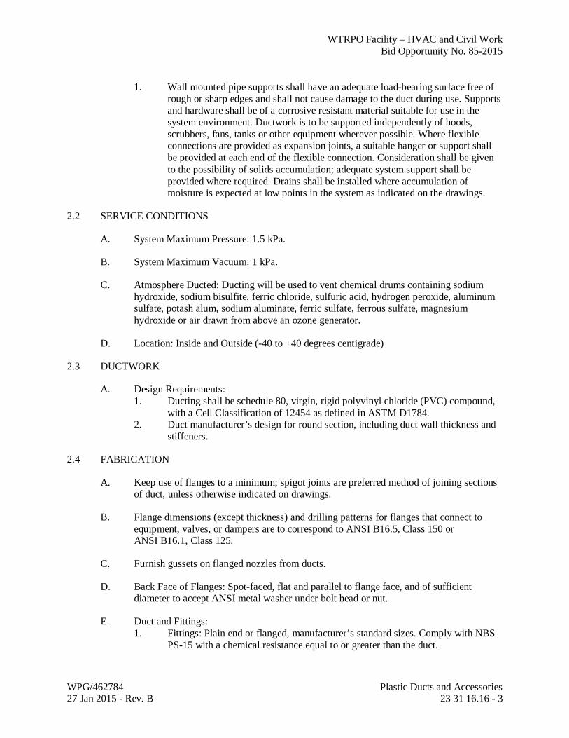
1. Wall mounted pipe supports shall have an adequate load-bearing surface free of rough or sharp edges and shall not cause damage to the duct during use. Supports and hardware shall be of a corrosive resistant material suitable for use in the system environment. Ductwork is to be supported independently of hoods, scrubbers, fans, tanks or other equipment wherever possible. Where flexible connections are provided as expansion joints, a suitable hanger or support shall be provided at each end of the flexible connection. Consideration shall be given to the possibility of solids accumulation; adequate system support shall be provided where required. Drains shall be installed where accumulation of moisture is expected at low points in the system as indicated on the drawings.
2.2 SERVICE CONDITIONS
A. System Maximum Pressure: 1.5 kPa.
B. System Maximum Vacuum: 1 kPa.
C. Atmosphere Ducted: Ducting will be used to vent chemical drums containing sodium hydroxide, sodium bisulfite, ferric chloride, sulfuric acid, hydrogen peroxide, aluminum sulfate, potash alum, sodium aluminate, ferric sulfate, ferrous sulfate, magnesium hydroxide or air drawn from above an ozone generator.
D. Location: Inside and Outside (-40 to +40 degrees centigrade)
2.3 DUCTWORK
A. Design Requirements: 1. Ducting shall be schedule 80, virgin, rigid polyvinyl chloride (PVC) compound,
with a Cell Classification of 12454 as defined in ASTM D1784. 2. Duct manufacturer’s design for round section, including duct wall thickness and
stiffeners.
2.4 FABRICATION
A. Keep use of flanges to a minimum; spigot joints are preferred method of joining sections of duct, unless otherwise indicated on drawings.
B. Flange dimensions (except thickness) and drilling patterns for flanges that connect to equipment, valves, or dampers are to correspond to ANSI B16.5, Class 150 or ANSI B16.1, Class 125.
C. Furnish gussets on flanged nozzles from ducts.
D. Back Face of Flanges: Spot-faced, flat and parallel to flange face, and of sufficient diameter to accept ANSI metal washer under bolt head or nut.
E. Duct and Fittings: 1. Fittings: Plain end or flanged, manufacturer’s standard sizes. Comply with NBS
PS-15 with a chemical resistance equal to or greater than the duct.
WTRPO Facility – HVAC and Civil Work Bid Opportunity No. 85-2015
WPG/462784 Plastic Ducts and Accessories 27 Jan 2015 - Rev. B 23 31 16.16 - 4
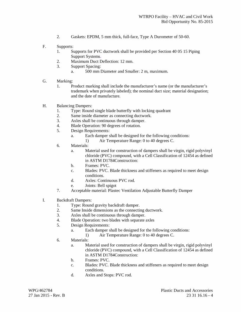
2. Gaskets: EPDM, 5 mm thick, full-face, Type A Durometer of 50-60.
F. Supports: 1. Supports for PVC ductwork shall be provided per Section 40 05 15 Piping
Support Systems. 2. Maximum Duct Deflection: 12 mm. 3. Support Spacing:
a. 500 mm Diameter and Smaller: 2 m, maximum.
G. Marking: 1. Product marking shall include the manufacturer’s name (or the manufacturer’s
trademark when privately labeled); the nominal duct size; material designation; and the date of manufacture.
H. Balancing Dampers: 1. Type: Round single blade butterfly with locking quadrant 2. Same inside diameter as connecting ductwork. 3. Axles shall be continuous through damper. 4. Blade Operation: 90 degrees of rotation. 5. Design Requirements:
a. Each damper shall be designed for the following conditions: 1) Air Temperature Range: 0 to 40 degrees C.
6. Materials: a. Material used for construction of dampers shall be virgin, rigid polyvinyl
chloride (PVC) compound, with a Cell Classification of 12454 as defined in ASTM D1784Construction:
b. Frames: PVC. c. Blades: PVC. Blade thickness and stiffeners as required to meet design
conditions. d. Axles: Continuous PVC rod. e. Joints: Bell spigot
7. Acceptable material: Plastec Ventilation Adjustable Butterfly Damper
I. Backdraft Dampers: 1. Type: Round gravity backdraft damper. 2. Same Inside dimensions as the connecting ductwork. 3. Axles shall be continuous through damper. 4. Blade Operation: two blades with separate axles 5. Design Requirements:
a. Each damper shall be designed for the following conditions: 1) Air Temperature Range: 0 to 40 degrees C.
6. Materials: a. Material used for construction of dampers shall be virgin, rigid polyvinyl
chloride (PVC) compound, with a Cell Classification of 12454 as defined in ASTM D1784Construction:
b. Frames: PVC. c. Blades: PVC. Blade thickness and stiffeners as required to meet design
conditions. d. Axles and Stops: PVC rod.
WTRPO Facility – HVAC and Civil Work Bid Opportunity No. 85-2015
WPG/462784 Plastic Ducts and Accessories 27 Jan 2015 - Rev. B 23 31 16.16 - 5
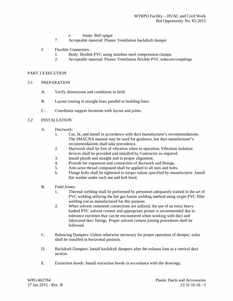
e. Joints: Bell spigot 7. Acceptable material: Plastec Ventilation backdraft damper
J. Flexible Connectors: 1. Body: flexible PVC using stainless steel compression clamps. 2. Acceptable material: Plastec Ventilation flexible PVC reducers/couplings
PART 3 EXECUTION
3.1 PREPARATION
A. Verify dimensions and conditions in field.
B. Layout routing in straight lines parallel to building lines.
C. Coordinate support locations with layout and joints.
3.2 INSTALLATION
A. Ductwork: 1. Cut, fit, and install in accordance with duct manufacturer’s recommendations.
The SMACNA manual may be used for guidance, but duct manufacturer’s recommendations shall take precedence.
2. Ductwork shall be free of vibration when in operation. Vibration isolation devices shall be provided and installed by Contractor as required.
3. Install plumb and straight and in proper alignment. 4. Provide for expansion and contraction of ductwork and fittings. 5. Anti-seize thread compound shall be applied to all nuts and bolts. 6. Flange bolts shall be tightened to torque values specified by manufacturer. Install
flat washer under each nut and bolt head.
B. Field Joints: 1. Thermal welding shall be performed by personnel adequately trained in the art of
PVC welding utilizing the hot gas fusion welding method using virgin PVC filler welding rod as manufactured for this purpose.
2. When solvent cemented connections are utilized, the use of an extra heavy bodied PVC solvent cement and appropriate primer is recommended due to tolerance extremes that can be encountered when working with duct and fabricated duct fittings. Proper solvent cement joining procedures shall be followed.
C. Balancing Dampers: Unless otherwise necessary for proper operation of damper, axles shall be installed in horizontal position.
D. Backdraft Dampers: Install backdraft dampers after the exhaust fans in a vertical duct section.
E. Extraction hoods: Install extraction hoods in accordance with the drawings.

WTRPO Facility – HVAC and Civil Work Bid Opportunity No. 85-2015
WPG/462784 Plastic Ducts and Accessories 27 Jan 2015 - Rev. B 23 31 16.16 - 6
F. Provide flexible connectors between ductwork and exhaust fans.
3.3 CLEANING
A. Dampers shall be smooth, clean, and free of dirt when installed.
END OF SECTION

WTRPO Facility – HVAC and Civil Work Bid Opportunity No. 85-2015
WPG/462784 Dampers - Balancing 27 Jan 2015 - Rev. A 23 31 14 - 1
SECTION 23 31 14
DAMPERS - BALANCING
PART 1 GENERAL
1.1 REFERENCES
A. Sheet Metal and Air Conditioning National Association (SMACNA) 1. SMACNA HVAC Duct Construction Standards, Metal and Flexible.
1.2 SUBMITTALS
A. Product Data: 1. Submit manufacturer's printed product literature, specifications and datasheet in
accordance with Section 01 33 00 - Submittal Procedures. Include product characteristics, performance criteria, and limitations.
2. Indicate the following: a. Specifications
B. Quality assurance submittals: submit following in accordance with Section 01 33 00 - Submittal Procedures. 1. Instructions: submit manufacturer's installation instructions.
1.3 DELIVERY, STORAGE AND HANDLING
A. Deliver, store and handle materials in accordance with manufacturer’s written instructions.
PART 2 PRODUCTS
2.1 ROUND SINGLE BLADE BALANCING DAMPERS
A. Damper Frame: minimum of 12 gauge, type 304 stainless steel formed into a rolled channel frame.
B. Blades: minimum of 16 gauge, type 304 stainless steel.
C. Axles: minimum 9 mm diameter , type 304 stainless steel.
D. Axle seals: O-ring stuffing boxes.
E. Bearings: nylon.
F. Locking quadrant damper.
WTRPO Facility – HVAC and Civil Work Bid Opportunity No. 85-2015
WPG/462784 Dampers - Balancing 27 Jan 2015 - Rev. A 23 31 14 - 2
PART 3 EXECUTION
3.1 INSTALLATION
A. Install in fume hood exhaust duct for balancing of system.
B. Install in accordance with recommendations of SMACNA and manufacturer's instructions.
C. Damper to be vibration free.
D. Ensure dampers are observable and accessible.
END OF SECTION
WTRPO Facility – HVAC and Civil Work Bid Opportunity No. 85-2015
WPG/462784 Fans 27 Jan 2015 - Rev. B 23 34 00 - 1
SECTION 23 34 00 FANS
PART 1 GENERAL
1.1 REFERENCES
A. The following is a list of standards which may be referenced in this section: 1. Acoustical Society of America (ASA): S2.19, Mechanical Vibration – Balance
Quality Requirement of Rigid Rotors – Part 1, Determination of Permissible Residual Unbalance.
2. Air Movement and Control Association International (AMCA): a. 99, Standards Handbook. b. 201, Fans and Systems. c. 203, Field Performance Measurement of Fan Systems. d. 210, Laboratory Methods of Testing Fans for Aerodynamic Performance
Rating. e. 300, Reverberant Room Method for Sound Testing of Fans. f. 301, Methods for Calculating Fan Sound Ratings from Laboratory Test
Data. 3. American Bearing Manufacturers Association (ABMA): 9, Load Ratings and
Fatigue Life for Ball Bearings. 4. American Society of Heating, Refrigerating, and Air-Conditioning Engineers
(ASHRAE): HVAC Applications Manual. a. 52.2 Method of Testing General Ventilation Air – Cleaning Devices for
Removal Efficiency by Particle Size. b. HVAC Applications Manual.
5. ASTM International (ASTM): a. B117, Standard Practice for Operating Salt Spray (Fog) Apparatus. b. E84, Standard Test Method for Surface Burning Characteristics of
Building Materials. 6. National Electrical Manufacturers Association (NEMA): MG 1, Motors and
Generators. 7. National Fire Protection Association (NFPA): 45, Fire Protection for Laboratories
Using Chemicals. 8. Occupational Safety and Health Act (OSHA). 9. Underwriters Laboratories Inc. (UL/ULC): 507, Electric Fans.
1.2 DEFINITIONS
A. The following is a list of abbreviations which may be used in this Section: 1. AC: Alternating Current. 2. CISD: Chemical Industry, Severe-Duty. 3. dB: Decibel. 4. DWDI: Double Width, Double Inlet. 5. FRP: Fiberglass Reinforced Plastic.

WTRPO Facility – HVAC and Civil Work Bid Opportunity No. 85-2015
WPG/462784 Fans 27 Jan 2015 - Rev. B 23 34 00 - 2
6. kW: Kilowatt. 7. ODP: Open Drip Proof. 8. SWSI: Single Width, Single Inlet. 9. TEFC: Totally Enclosed, Fan Cooled. 10. UV: Ultra Violet 11. XP: Explosion Proof.
1.3 SUBMITTALS
A. Action Submittals: 1. Provide for all products specified, as follows:
a. Identification as referenced in Contract Documents. b. Manufacturer’s name and model number. c. Descriptive specifications, literature and drawings. d. Dimensions and weights. e. Fan sound power level data (reference 10 to power minus 12 Watts) at
design operating point. f. Fan Curves:
1) Performance Curves Indicating: a) Relationship of flow rate to static pressure for various
fan speeds. b) Brake horsepower curves. c) Acceptable selection range (surge curves, maximum
revolutions per minute, etc). d) Static pressure, capacity, horsepower demand and overall
efficiency required at the duty point, including drive losses.
g. Capacities and ratings. h. Construction materials. i. Fan type, size, class, drive arrangement, discharge, rotation and bearings. j. Wheel type, diameter, revolutions per minute, and tip speed. k. Motor data. l. Power and control wiring diagrams, including terminals and numbers. m. Vibration isolation. n. Factory finish system. o. Color selection charts where applicable.
2. a. Where submitted equipment results in change to fan inlet or outlet
ductwork configuration shown on drawings, submit system effect factor calculations indicating increased static pressure requirements as described in AMCA 201.
b. Where submitted equipment results in change to ductwork and equipment configuration shown on drawings, submit detailed information on structural, mechanical, electrical, or other modifications necessary to adapt arrangement to equipment furnished.
B. Informational Submittals:
WTRPO Facility – HVAC and Civil Work Bid Opportunity No. 85-2015
WPG/462784 Fans 27 Jan 2015 - Rev. B 23 34 00 - 3
1. Recommended procedures for protection and handling of products prior to installation.
2. Manufacturer’s installation instructions. 3. Test reports. 4. Operation and maintenance data in conformance with Section 01 78 23, Operation
and Maintenance Data. Include as-built version of equipment schedules.
1.4 QUALITY ASSURANCE
A. Performance Ratings: Tested in accordance with AMCA 210.
B. Sound Ratings: Tested in accordance with AMCA 300.
C. Fabrication: In accordance with AMCA 99.
1.5 EXTRA MATERIALS
A. Furnish, tag, and box for shipment and storage the following spare parts, and special tools: Item Quantity
Special tools required to maintain or dismantle
One complete set for each different size unit
B. Delivery: In accordance with Section 01 61 00, Common Product Requirements.
PART 2 PRODUCTS
2.1 EQUIPMENT SCHEDULES
A. Some specific equipment requirements are listed in Equipment Schedules. Refer to Drawings and the attached equipment schedules for details.
2.2 NAMEPLATES
A. All units shall include factory installed permanently attached nameplate displaying unit model and serial number.
2.3 OPERATING LIMITS
A. Fans designated to meet a specified fan class shall comply with requirements of AMCA 99-2408-69.
2.4 FAN DRIVES (Not applicable for direct drive external rotor motorized impeller type).
A. Drive assembly shall be sized for a minimum 140 percent of fan motor horsepower rating.
B. Fan Shafts: First critical speed of at least 125 percent of fan maximum operating speed.
WTRPO Facility – HVAC and Civil Work Bid Opportunity No. 85-2015
WPG/462784 Fans 27 Jan 2015 - Rev. B 23 34 00 - 4
2.5 CENTRIFUGAL CHEMICAL EXHAUST FAN
A. General: 1. Factory-assembled centrifugal fan, direct drive, forward curved impeller type,
upblast discharge; including housing, fan wheel, drive assembly, motor and accessories.
B. Materials: 1. Casing, Motor Plates, Hub Cap, Inlet Flange: Polypropylene 2. Impeller: Injection molded polypropylene homopolymer. 3. Gaskets: Polytetrafluoroethylene. 4. Motor Support Stand: 316 stainless steel
C. Manufacturers and Products: 1. Plastec Ventilation Inc, Axair Fans, Esco 2. Other as approved by Contract Administrator
2.6 MOTORS
A. General: 1. Provide integral self-resetting overload protection on single-phase motors. 2. Motors for fans specified for use with variable frequency drives shall be inverter
duty type. 3. Motors shall not operate into service factor in any case.
B. Motor requirements shall be as follows, unless designated otherwise on Equipment Schedule: 1. Torque Characteristics: Sufficient to accelerate driven loads satisfactorily. 2. Winding Thermal Protection: None. 3. Space Heater: No. 4. Number of Speeds: Single. 5. Shaft Type: Solid, carbon steel. 6. Mounting: As required for fan arrangement. 7. Service Factor: 1.15.
2.7 ACCESSORIES
A. Equipment Identification Plates: Furnish 16-gauge Type 304 stainless steel identification plate securely mounted on each separate equipment component and control panel in a readily visible location. Plate shall bear 10 mm high engraved block type black enamel filled equipment identification number and letters indicated in this Specification and as shown on Drawings.
2.8 SOURCE QUALITY CONTROL
A. General:
WTRPO Facility – HVAC and Civil Work Bid Opportunity No. 85-2015
WPG/462784 Fans 27 Jan 2015 - Rev. B 23 34 00 - 5
1. Fan shall operate at single stable point as indicated by fan curve. Fans having two potential operating points are not acceptable.
2. Motor shall not operate into motor service factor in any listed case. 3. Consider drive efficiency in motor selection according to manufacturer’s published
recommendation or according to AMCA 203, Appendix L.
B. Balancing: 1. Unless noted otherwise, each fan wheel shall be statically and dynamically
balanced to ASA S2.19 Grade G6.3.
PART 3 EXECUTION
3.1 INSTALLATION
A. Install fans level and plumb.
B. Labeling: 1. Label fans in accordance with Article, Accessories. 2. Mark exhaust fans serving fume hoods with arrows to indicate proper direction of
rotation, in accordance with NFPA 45.
C. Service Access: Locate units to provide access spaces required for motor, drive, bearing servicing, and fan shaft removal.
D. Connections 1. Refer to Section 23 31 16, Plastic Ductwork and Accessories 2. Install ductwork adjacent to fans to allow proper service and maintenance.
3.2 FIELD QUALITY CONTROL
A. Functional Tests: 1. Verify blocking and bracing used during shipping are removed. 2. Verify fan is secure on mountings and supporting devices, and connections to
ducts and electrical components are complete. 3. Verify proper thermal-overload protection is installed in motors, starters, and
disconnect switches. 4. Verify that cleaning and adjusting are complete. 5. Disconnect fan drive from motor (if applicable); verify proper motor rotation
direction, and verify fan wheel free rotation and smooth bearing operation. 6. Reconnect fan drive system; align and adjust belts and install belt guards. 7. Verify lubrication for bearings and other moving parts. 8. Verify manual and automatic volume control and fire and smoke dampers in
connected ductwork are in fully open position.
B. Performance Tests: 1. Starting Procedures:
WTRPO Facility – HVAC and Civil Work Bid Opportunity No. 85-2015
WPG/462784 Fans 27 Jan 2015 - Rev. B 23 34 00 - 6
a. Energize motor and adjust fan to indicated revolutions per minute. b. Measure and record motor voltage and amperage.
2. Operational Test: a. After electrical circuitry has been energized, start units to confirm proper
motor rotation and unit operation. b. Repair or replace malfunctioning units; retest as specified after repairs or
replacement is made. c. Test and adjust control safeties. d. Replace damaged and malfunctioning controls and equipment.
3.3 ADJUSTING
A. Lubricate bearings.
3.4 CLEANING
A. After completing system installation, including outlet fitting and devices, inspect exposed finish. Remove burrs, dirt, and construction debris, and repair damaged finishes.
B. On completion of installation, internally clean fans according to manufacturers’ written instructions. Remove foreign material and construction debris. Vacuum fan wheel and cabinet.
3.5 SUPPLEMENTS
A. The supplements listed below, following “End of Section,” are a part of this Specification. 1. 23 34 00.01, Fan Schedule
END OF SECTION
WTRPO Facility – HVAC and Civil Work Bid Opportunity No. 85-2015
FAN SCHEDULE
WPG/462784 Fan Schedule 27 Jan 2015 - Rev. B 23 34 00 Supplement - 1
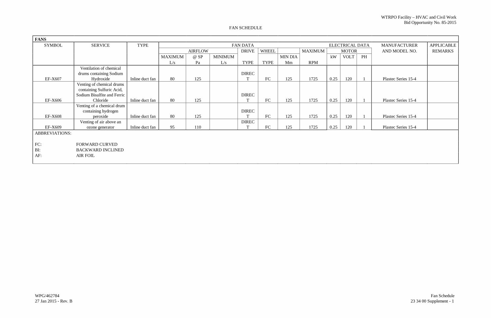
FANS SYMBOL SERVICE TYPE FAN DATA ELECTRICAL DATA MANUFACTURER APPLICABLE
AIRFLOW DRIVE WHEEL MAXIMUM MOTOR AND MODEL NO. REMARKS MAXIMUM @ SP MINIMUM MIN DIA kW VOLT PH L/s Pa L/s TYPE TYPE Mm RPM
EF-X607
Ventilation of chemical drums containing Sodium
Hydroxide Inline duct fan 80 125 DIREC
T FC 125 1725 0.25 120 1 Plastec Series 15-4
EF-X606
Venting of chemical drums containing Sulfuric Acid,
Sodium Bisulfite and Ferric Chloride Inline duct fan 80 125
DIRECT FC 125 1725 0.25 120 1 Plastec Series 15-4
EF-X608
Venting of a chemical drum containing hydrogen
peroxide Inline duct fan 80 125 DIREC
T FC 125 1725 0.25 120 1 Plastec Series 15-4
EF-X609 Venting of air above an
ozone generator Inline duct fan 95 110 DIREC
T FC 125 1725 0.25 120 1 Plastec Series 15-4 ABBREVIATIONS: FC: FORWARD CURVED BI: BACKWARD INCLINED AF: AIR FOIL
WTRPO Facility – HVAC and Civil Work Bid Opportunity No. 85-2015
WPG/462784 Fume Hoods 27 Jan 2015 - Rev. A 23 38 16.13 - 1
SECTION 23 38 16.13
FUME HOODS
PART 1 GENERAL
1.1 REFERENCES
A. American Society of Heating, Refrigerating and Air Conditioning Engineers (ASHRAE) 1. ASHRAE Standard 41.2, Standard Method for Laboratory Air Measurement 2. ASHRAE Standard 110, Method of Testing Performance of Laboratory Fume
Hoods.
B. Canadian Standards Association (CSA) 1. CSA Z316.5 Fume Hoods and Associated Exhaust System.
C. CSA National Standards Institute (ANSI)/American Industrial Hygiene Association (AIHA) 1. ANSI/AIHA Z9.5 Laboratory Ventilation.
D. American Society for Testing and Materials (ASTM) 1. ASTM A653 Standard Specification for Steel Sheet, Zinc-Coated (Galvanized)
or Zinc-Iron Alloy-Coated (Galvannealed) by the Hot Dip Process. 2. ASTM A480/A480M: Standard Specification for General Requirements for Flat-
Rolled Stainless and Heat-Resisting Steel Plate, Sheet and Strip. 3. ASTM A1008/A1008M: Standard Specification for Steel, Sheet, Cold-Rolled,
Carbon Structural, High Strength Low-Alloy with Improved Formability. 4. ASTM B117 Standard Practice for Operating Salt Spray (Fog) Apparatus. 5. ASTM D522: Standard Test Methods for Mandrel Bend Test of Attached
Organic Coatings. 6. ASTM D523: Standard Test Method for Specular Gloss. 7. ASTM D2247: Standard Practice for Testing Water Resistance of Coating in
100% Relative Humidity. 8. ASTM D3359: Standard Test Methods for Measuring Adhesion by Tape Test. 9. ASTM D3363: Standard Test Method for Film Hardness by Pencil Test. 10. ASTM D4060: Standard Test Method for Abrasion Resistance of Organic
Coatings by the Water Abraser. 11. ASTM E84: Standard Test Method for Surface Burning Characteristics of
Building Materials.
E. Underwriters Laboratories (UL) 1. UL 1805 – Laboratory Fume Hoods.
1.2 SUBMITTALS
A. Instruction covering usage and proper operation of the fume hood shall be provided.
WTRPO Facility – HVAC and Civil Work Bid Opportunity No. 85-2015
WPG/462784 Fume Hoods 27 Jan 2015 - Rev. A 23 38 16.13 - 2
B. Submit copy of the corrosion resistant label to be attached to the fume hood exterior with condensed information covering recommended locations for apparatus and accessories.
C. Submit copy of the corrosion resistant label to be attached to the interior baffle indicating baffle positions.
D. Written instructions in booklet form providing additional detail information on safe, proper operation and maintenance.
E. Submit in accordance with Section 01 78 00 – Closeout Submittals. 1. Submit manufacturer’s printed product literature, specifications and data sheet.
Include product characteristics, performance criteria, and limitations. 2. Indicate performance data and specifications.
F. Submit manufacturer’s installation instructions.
G. Closeout Submittals: 1. Provide maintenance data for incorporation into manual specified in Section 01
78 00 - Closeout Submittals
1.3 DELIVERY, STORAGE AND HANDLING
A. Packing, shipping, handling and unloading: 1. Deliver, store and handle in accordance with manufacturer's written instructions
and Section 01 61 00 - Common Product Requirements. 2. Deliver, store and handle materials in accordance with manufacturer’s written
instructions. 3. Crate all fume hoods for shipping, handling and storage. 4. Protect Laboratory Fume Hood finish surfaces during shipment and installation.
Do not remove until immediately prior to final inspection.
1.4 DESIGN
A. Fume hoods shall be designed and constructed in accordance with UL 1805.
B. Hoods shall function as ventilated, enclosed work spaces, designed to capture confine and exhaust fumes, vapours and particulate matter produced or generated within the enclosure.
C. Laboratory fume hoods shall provide safe operation when properly installed and connected to an exhaust system, and shall provide proper evacuation of air volume to permit the fume hoods to operate at specified face velocity. They shall be designed for consistent and safe air flow through hood face and negative variations of face velocity exceeding 10% of average face velocity at any designated measuring point as defined in this section.
WTRPO Facility – HVAC and Civil Work Bid Opportunity No. 85-2015
WPG/462784 Fume Hoods 27 Jan 2015 - Rev. A 23 38 16.13 - 3
1.5 PERFORMANCE REQUIREMENTS
A. Fume hoods shall be designed to meet or exceed the American Standard for Laboratory Ventilation and the American Industrial Hygiene Association standard as described in ANSI/AIHA Z9.5. This standard of performance shall be verifiable through testing at an independent and certified testing facility, which conducted the tests in accordance with the established protocol as set out by the ANSI/AHSRAE 110 standard.
B. Manufacturer shall provide certified copied of test results upon request by the Owner’s Representative.
1.6 FACTORY FUME HOOD TEST FACILITY
A. Manufacturer of fume hoods shall have the capability within his own plant facility of performing fume hood tests based on the latest ANSI/ASHRAE Standard 110.
PART 2 PRODUCTS
2.1 MATERIALS
A. Hood exterior construction shall be 20 gauge (or heavier) cold rolled sheet steel or galvanized steel supports. All exterior painted surfaces shall be baked on, dry powder epoxy applied electrostatically. Base metal material shall be properly prepared for epoxy coating.
B. Hood interior liner and baffle shall be molded fiberglass reinforced polyester resin with a white gel coated surface. Nominal thickness shall be 4.75 mm. Flame spread shall be less than or equal to 25 per ASTM E-84.
C. Integral blower shall be corrosion-resistant, direct drive.
D. Blower motor: 120V/1Ø/60Hz.
E. Exhaust connection shall be fiberglass molded into the liner and same material as the liner.
F. Hood sash shall be 4.75 mm thick tempered safety glass with epoxy-coated aluminum handle.
G. Air foil shall be 18 gauge epoxy-coated cold-rolled steel.
2.2 GENERAL
A. Overall exterior dimensions 762 mm wide x 766 mm deep x 1,219 mm high.
B. The bench-mounted laboratory hood with by-pass design shall minimize face velocity fluctuations as the sash is raised or lowered. With the sash positioned 150 mm above the
WTRPO Facility – HVAC and Civil Work Bid Opportunity No. 85-2015
WPG/462784 Fume Hoods 27 Jan 2015 - Rev. A 23 38 16.13 - 4
air foil, the average inflow velocity shall not be less than twice the selected full open face velocity nor greater than three times that amount.
C. Integral blower shall be capable of overcoming a maximum external static pressure of 30 Pa at 150 l/s using 250 mm diameter duct.
D. The exhaust connection shall be 170 mm inside diameter.
E. Right side fixture panel shall be factory-prepared to accept up to three service fixtures, one electrical duplex and one airflow monitor.
F. Removable front panel shall provide access to integral blower, plumbing fixtures, electrical wiring, counterbalance sash weight, and lighting fixtures, where specified on the individual hoods.
G. The air foil shall be located directly across the bottom of the sash opening to allow the air to bypass underneath the foil and sweep across the work surface to prevent any back flow of fumes escaping from the front of the hood.
H. The front and side exterior of the hood shall feature baked on powder epoxy paint applied electrostatically.
I. The liner and baffle(s) shall be one piece molded construction with smooth corners and no access panels. The tamper-resistant, preset baffle shall be one piece molded without slots or need for adjustment. The baffle shall provide uniform draw throughout the fume cavity. Baffle(s) shall be easily removable for cleaning.
J. The sash shall a single vertical-rising sash counterbalanced by a single weight suspended by two vinyl-coated stainless steel cables that pass through ball bearing pulleys. The sash shall operate smoothly without tilting when raised or lowered from either end and shall remain at rest in any open position. All sashes shall be framed with extruded epoxy-coated aluminum and PVC. No sheet liner will be accepted.
K. The hoods shall be equipped without service fixtures.
L. Vapor-proof model hoods shall be provided with 100-watt incandescent lamp. Hoods shall be provided with a light switch, blower switch, and all internal wiring to a single point internal junction box.
M. The vapor-proof hoods shall be factory-prepared to accept one electrical duplex receptacle as required.
N. Face velocity alarms to monitor hood performance shall be factory installed.
O. Aceptable Material 1. Labconco Catalog No. 3030000 or equal in accordance with B7.
WTRPO Facility – HVAC and Civil Work Bid Opportunity No. 85-2015
WPG/462784 Fume Hoods 27 Jan 2015 - Rev. A 23 38 16.13 - 5
2.3 BASE CABINET
A. Cabinet: Durable epoxy-coated steel construction with manual closing, non-locking doors. Includes four leveling feet . Sized to accommodate the fume hood.
B. Worksurface: Flat solid epoxy.
C. Acceptable Material: 1. Labconco Catalog No. 9900200 or equal in accordance with B7. 2. Labconco Catalog No. 4882805 or equal in accordance with B7.
PART 3 EXECUTION
3.1 EXAMINATION
A. Verify equipment rough-in before proceeding with work.
B. Coordinate with other trades for the proper and correct installation of electrical rough-in and for rough opening dimensions required for the installation of the hood.
3.2 INSTALLATION
A. Install according to manufacturer's instructions.
B. Install according to standards required by authority having jurisdiction.
C. Install equipment plumb, square and straight with no distortion and securely anchor as required.
D. Sequence installations to ensure utility connections are achieved in an orderly and expeditious manner.
E. Touch up minor damaged surfaces caused by installation. Replace damaged components as directed by Contact Administrator.
3.3 CLEANING
A. Clean equipment, casework, countertops and all other surfaces as recommended by the manufacturer, rendering all work in a new and unused appearance.
3.4 PROTECTION OF FINISHED WORK
A. Provide all necessary protective measures to prevent exposure of equipment and surfaces from exposure to other construction activity.
WTRPO Facility – HVAC and Civil Work Bid Opportunity No. 85-2015
WPG/462784 Fume Hoods 27 Jan 2015 - Rev. A 23 38 16.13 - 6
3.5 TESTING CRITERIA
A. Reverse Airflows and Containment - When tested as "As Manufactured" ("AM"), the hood shall provide containment less than or equal to 0.10 ppm when tested per ASHRAE Standard 110-95 and under the conditions specified in section X.X.X.01 of this specification.
B. Test Criteria: The following test criteria shall apply when determining the AM performance rating. 1. Face velocity: 0.51 m/s ±20% 2. Ambient temperature: 20 to 23°CF
C. Containment per ASHRAE 110-95 - At a tracer gas release rate of 4 liters per minute, the AM leakage shall not exceed 0.10 ppm (rating = 4 AM 0.10)
D. Flow Visualization - The following excerpt sections of ASHRAE 110-95 are used to define the AM test criteria for reverse airflow and exhaust capacity. 1. Flow Visualization - Swab a strip of titanium tetrachloride along both walls and
the hood floor in a line parallel to the hood face and 6 inches (152 mm) back into the hood. (Titanium tetrachloride is corrosive to the skin and extremely irritating to the eyes and respiratory system.) Swab an 8" (200 mm) circle on the baffle of the hood on centerline and on each side. Define air movement toward the face of the hood as reverse airflow and define lack of movement as dead air space. Swab the work surface, making sure to swab lines around all equipment in the hood. All smoke should be carried to the back of the hood and out. Test the operation of the lower air bypass air flow opening by running the cotton swab under the air foil. Before going on to the next test, move the cotton swab around in the face of the hood. If there is any outfall, the exhaust capacity test should not be made.
E. Exhaust Capacity - Ignite and place a 30-second smoke bomb near the center of the work surface, making sure that the hole on the side of the smoke bomb faces into the hood. After the smoke bomb begins to work, pick it up with tongs and move it around in the hood. There should be no visual or odor indications of smoke outside the hood.
F. Installed Performance - Per ASHRAE 110-95, the "AU" (As Used) requirement involves the design of the room supply system and the toxicity of the materials handled in the hood. The AU specification should be tailored to suit the needs of the laboratory room location.
END OF SECTION