Written By: Tekla Labs - Amazon Web Services · Written By: Tekla Labs Magnetic Stirrer ... Protein...
10
Magnetic Stirrer Designed by M.J. Watts (formerly of Massey University). Design open-source courtesy of Massey University New Zealand. Written By: Tekla Labs Magnetic Stirrer © 2017 guides.teklalabs.org Page 1 of 10
Transcript of Written By: Tekla Labs - Amazon Web Services · Written By: Tekla Labs Magnetic Stirrer ... Protein...

Magnetic StirrerDesigned by M.J. Watts (formerly of Massey University). Design open-source courtesy of Massey
University New Zealand.
Written By: Tekla Labs
Magnetic Stirrer
© 2017 guides.teklalabs.org Page 1 of 10

INTRODUCTION
Uses: Magnetic stirrers (also known as magnetic stir plates) are very common in experimentalchemistry and biology. They are used to mix components (solids and liquids) to get homogeneousliquid mixtures. Common examples include bacterial growth media and buffer solutions.
How They Work: Magnetic stirrers mix solutions using an external magnetic field that rotates asmall magnetic bar that has been placed in the mixture of interest.
Advantages: Magnetic stirrers minimize the risks of contamination since only an inert magnet bar,which can easily be cleaned, is put inside the sample/fluid. In addition, using a magnetic stirrer ratherthan manual stirring is critical for consistent, reproducible mixing or mixing over long time scales.Protein dialysis, for example, requires multi-hour or overnight sample mixing and is sensitive tobacterial contamination.
This Magnetic Stirrer: Can rotate an internal magnet at variable speeds, mixing volumes up to oneliter. Glassware with a stir bar is placed directly on top of the stirrer unit. The device is battery-operated and largely isolated from spills by its plastic case and gasket.
TOOLS:Drill (1)
Screw Driver (1)
Soldering gun (1)
PARTS:Project box (1)
DC Motor (1)
Magnetic Stir Bar (1)
LED (1)
Electrical compontents (described below)(1)
Rare earth magnets (1)
Hardboard (1)
Printed Circuit Board (1)
Knob (1)
1 1.5V D cell battery (1)
Magnetic Stirrer
© 2017 guides.teklalabs.org Page 2 of 10

Step 1 — Module 1, Motor Assembly (photo 1)
Component list: (1) motor mount - sheet metal, (2) DC motor, (3) rotor body, (4) rotor mount -sheet metal, (5) magnets, (6) screw
Task 1, Rotor Mount Fabrication
Cut rotor mount metal strip from bulk strip metal. (photo 2)
Rotor mount length is set by the by desired magnet location. It is spaced approximately 80%of the stir bar length. Using longer bar magnets on the rotor body allows for a wider range ofmagnetic stir bar sizes.
Drill Holes
The motor shaft through hole (red) should be larger then the shaft (R).
The screw holes (r) to attach to the Rotor Body are spaced symmetrically (L) around thecenter. Be careful not to place them too far, where the magnets will be attached.
Magnetic Stirrer
© 2017 guides.teklalabs.org Page 3 of 10

Step 2 — Module 1, Motor Assembly
Task 2, Rotor Body Fabrication: partnumbers 3, 4 & 5 in the image instep 1
Cut hardboard to form the rotor body
The rotor body’s diameter isdependent on the size of the stirbar you will be using (asdiscussed in Rotor MountFabrication). Our rotor is 38 mmin diameter and 5 mm thick
Drill two screws (or holes, if you’reusing machine screws) through thebottom base of the hardboard.
Install the magnetic strip rotor atopthe drilled hardboard using thecorresponding nuts
Glue magnets onto the metal strip onthe hardboard rotor. Magnet distanceshould be about 80% of the length ofthe stir bar.
Magnetic Stirrer
© 2017 guides.teklalabs.org Page 4 of 10
Step 3 — Module 1, Motor Assembly
Task 3, Motor Mount Fabrication
Cut out a metal sheet for the Metal Mount. Length should be enough to realize the structuresdepicted in photo 1.
Drill holes for motor screws and shaft in the motor mount sheet (photo 1)
CAUTION: clamp sheet metal to work surface while drilling. Keep hands free of sheet metal incase it comes free and rotates with the drill.
Positions of holes for motor screws and shaft are critical. These depend on the exact model ofmotor that is used. For most precise placement, first mark hole position in pencil. Then indentthe sheet metal surface with an awl or nail. Finally, position tip of drill bit in the indentation.
Bend the motor mount sheet to form the metal motor mount shape described below. The mountheight (30 mm in this case) should be high enough to fit the motor without compressing its solderleads. The angle you bend the sheet is not critical. (photo 2)
Attach motor to the motor mount sheet with screws. Screws with short heads should be used sothat there is enough clearance to the rotor body. (photo 3)
Magnetic Stirrer
© 2017 guides.teklalabs.org Page 5 of 10

Step 4 — Module 1, Motor Assembly
Task 4, Final Motor Assembly
Press-fit the rotor body onto the motor shaft.
This is a friction fit. The motor shaft can be covered by a piece of heatshrink plastic to provide afirm fit to the hole in the center of the hardboard rotor body.
Solder the two motor wires to contacts on the printed circuit board (one to ground and one so that itcan be electrically connected to the potentiometer).
Attach the motor mount sheet (with attached motor) to the printed circuit board with screws.
Magnetic Stirrer
© 2017 guides.teklalabs.org Page 6 of 10

Step 5 — Module 2, Motor Controller for speed control
Construct a PCB according to the circuit shown below. Alternately, a hand-wired circuit may besimpler to construct with available parts. (Tekla Labs is working on converting this circuit diagraminto a more accessible form and photographing the hand-wiring step-by-step.)
Drill a hole through the plastic casing to connect the speed control knob to the potentiometer.
Attach knob to potentiometer shaft outside of case
http://www.pcb.com
Magnetic Stirrer
© 2017 guides.teklalabs.org Page 7 of 10
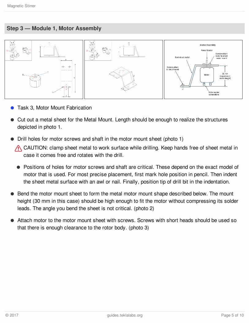
Step 6 — Module 3, Install Battery and LED
Task 1, Battery Installation (photo 1)
Solder the two battery casing wires to contacts on the printed circuit board. One wire must beconnected to ground and one must be connected to a contact so that the wire can be electricallyconnected to the potentiometer.
Glue the battery casing to the PCB. Hotmelt, a hot glue gun can be used for this step.
Task 2, LED installation (photo 2)
Drill a hole on the side of the plastic casing to fit the LED light to provide a tight fit.
Solder the two LED light wires to contacts on the printed circuit board (one to ground and one sothat it can be electrically connected between the potentiometer and the motor.
Carefully press the LED light into the hole using pliers.
Magnetic Stirrer
© 2017 guides.teklalabs.org Page 8 of 10
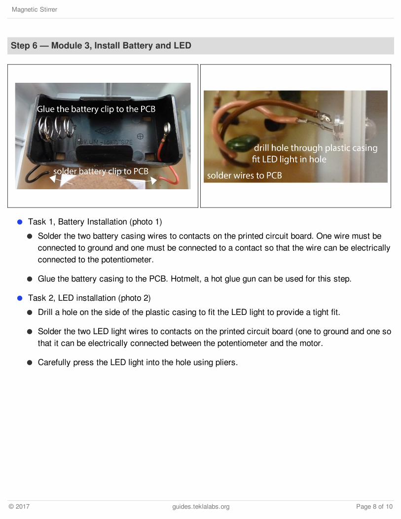
Step 7 — Module 4, Final Assembly
Screw circuit board into bottom ofplastic case
Place D-battery into battery clips
Screw top onto plastic case body
Do not over-tighten as this couldcause the uneven pressure loadalong the perimeter and thusbowing (outward bending) of thetop that affects the distancebetween the glass beaker and themagnetic rotor.
Device Inspection
The unit should be completelysealed, but without over-tighteningof the screws used to attach thetop surface. There should be noentry points into the unit otherthan the holes cut for the indicatorlight (if used) and for the speedcontrol knob.
When turning the unit on, with aworking battery in place, the LEDindicator light should turn on.
Magnetic Stirrer
© 2017 guides.teklalabs.org Page 9 of 10
This document was last generated on 2017-06-17 11:18:39 AM.
Step 8 — Module 5, Testing
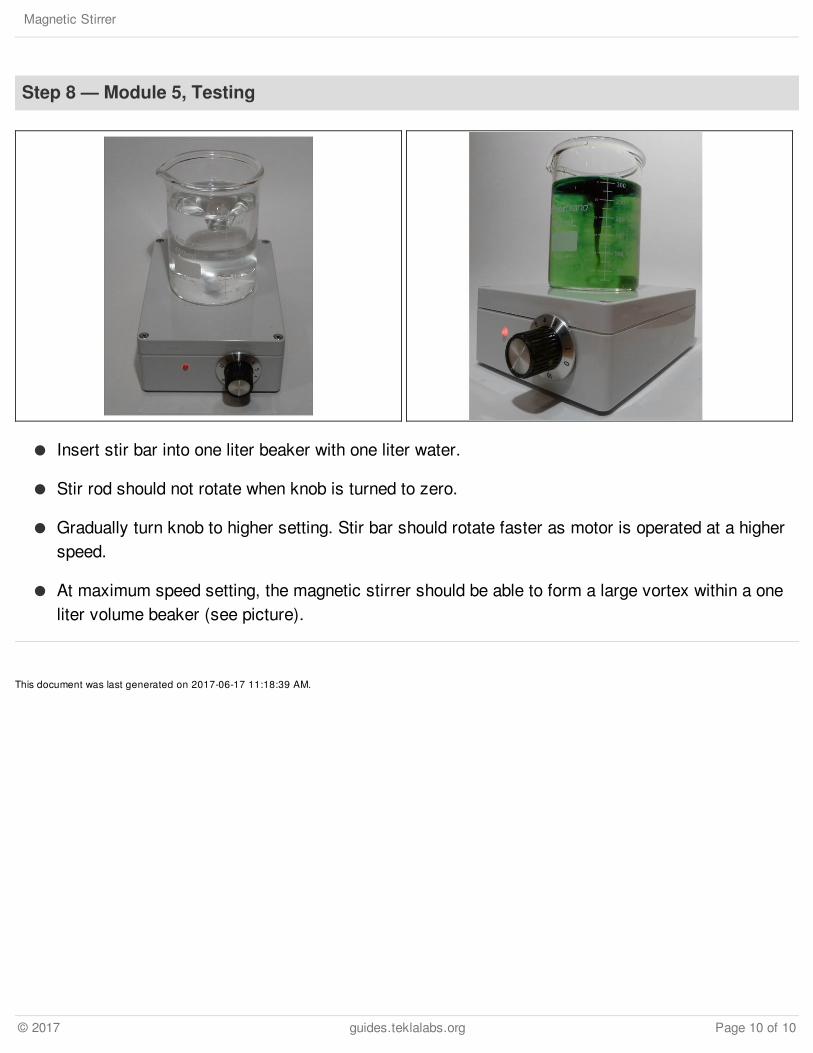
Insert stir bar into one liter beaker with one liter water.
Stir rod should not rotate when knob is turned to zero.
Gradually turn knob to higher setting. Stir bar should rotate faster as motor is operated at a higherspeed.
At maximum speed setting, the magnetic stirrer should be able to form a large vortex within a oneliter volume beaker (see picture).
Magnetic Stirrer
© 2017 guides.teklalabs.org Page 10 of 10