WRIGHT PUMP - wft.salesmrc.comwft.salesmrc.com/pdfs/TRA400_IOM.pdf · Wright Pump TRA 400 series...
20
WRIGHT PUMP S84W18693 ENTERPRISE DRIVE MUSKEGO, WI 53150 Phone 262-679-8000 Fax 262-679-2026 www.wrightpump.com TRA 400 SERIES HIGH PURITY INSTRUCTION AND MAINTENANCE MANUAL March 27, 2006
Transcript of WRIGHT PUMP - wft.salesmrc.comwft.salesmrc.com/pdfs/TRA400_IOM.pdf · Wright Pump TRA 400 series...
WRIGHT PUMP
S84W18693 ENTERPRISE DRIVE MUSKEGO, WI 53150
Phone 262-679-8000
Fax 262-679-2026 www.wrightpump.com
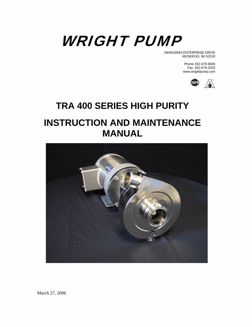
TRA 400 SERIES HIGH PURITY
INSTRUCTION AND MAINTENANCE MANUAL
March 27, 2006

2
DESCRIPTION Wright Pump TRA 400 series centrifugal pumps are designed to be safe and reliable when properly used and maintained. These pumps are designed for flooded suction applications only. Internal mechanical seals MUST NEVER RUN DRY – Provide liquid to pump and seal flush (if applicable) before operating pump. Motors used on Softwave Pumps are standard NEMA totally enclosed fan cooled (TEFC) motors. They are C-faced with a locked front bearing to minimize motor shaft end play. Replacement motors are available from local motor distributors or from Softwave Pumps, LLC. SAFETY Installers, operators and maintenance personnel must follow safety measures. Failure to observe the instructions in this manual could result in personal injury or machine damage.
• Do not operate pump beyond the rated conditions for which the pump was sold. • Do not use heat or excessive force to disassemble pump due to risk of explosion of
trapped liquid or damage to pump. • Do not operate pump without shaft guard properly installed. • Shut off and drain product from pump prior to disconnecting piping.
!!!
DANGER: BEGIN ALL PUMP MAINTENANCE OPERATIONS BY DISCONNECTING THE ENERGY SOURCE TO THE PUMP. OBSERVE ALL LOCK OUT/TAG OUT PROCEDURES AS OUTLINED BY ANSI Z244.1-1982 AND OSHA 1910.147 TO PREVENT ACCIDENTAL START-UP AND INJURY.

3
TABLE OF CONTENTS Description……………………………………………………………………2 Safety…………………………………………………………………………2 Table of Contents……………………………………………………………..3 General Information…………………………………………………………..4 Technical Information………………………………………………………...5 Seal Maintenance & Lubrication……………………………………………..6 Pump Rotation ……………………………………………………………….6 Installation and Piping Guidelines……………………………………………7 Seal Replacement……………………………………………………………..9 Shaft Replacement……………………………………………………………10 Seal Assembly Drawings……………………………………………………..13 Softsterile™ Seal Flush Diagram…………………………………………….17 Zero Dead-Leg Drain Diagram……………………………………………….17 Seal Flushing Adjustment……………………………………………………..18 Warranty……………………………………………………………………....20
4
GENERAL INFORMATION SHIPPING DAMAGE Inspect your shipment immediately. If shipping damage is found, note it on the drivers’ copy of the documentation. Ask the driver to acknowledge and initial the description of the damage. You are responsible for initiating shipping damage claims. HIDDEN DAMAGE If you discover hidden damage caused by shipping after pump has been received, contact the carrier immediately and ask them for an inspection of the damage. Contact Wright Pump and notify them of the problem. WARRANTY CLAIM
Please read the warranty statement (page16) to correctly determine if you have a claim. For warranty claims you must have a “Returned Goods Authorization” (RGA) from Wright Pump before any returns will be accepted. Remember, motors are covered by the motor manufacturer’s warranty.
INTRODUCTION
This manual contains information on the installation, operation, repair and maintenance of Wright Pump TRA 400 series centrifugal pumps.
The Wright Pump TRA 400 series pumps have been designed specifically for high purity liquid pumping applications where product integrity cannot be complicated. This pump was constructed with the greatest attention to quality as possible to ensure your satisfaction. Setting a new standard for high purity liquid transfer, Wright Pump machines all of the product contact components from solid (wrought) 316L stainless steel bar or plate, eliminating any possibility of contamination due to pits, cracks, crevices or potentially high levels of ferrite that may cause rouging typically found in castings. Machining from solid 316L stainless steel allow us to reduce internal clearances providing for low NPSH requirements.
5
TECHNICAL INFORMATION
MATERIALS OF CONSTRUCTION:
Product contact surfaces………………………AISI 316L stainless steel from bar or plate
Gaskets and O-Rings…………………...Viton® is standard unless specified by purchaser
Surface finishes…………………………………………………….Specified by purchaser
MOTOR INFORMATION
Standard NEMA TEFC C-face motors. 3 phase, 60 Hz, 208-230/460VAC (standard) unless specified by purchaser
RECOMMENDED TORQUE VALUES:
Housing nuts……………………………………………………………..40-50 ft.-lbs.
Impeller nut………………………………………………………………70-80 ft.-lbs.
Shaft collar screw (through 184TC frame motors)…………………………220 lb.-in.
Shaft collar screw (213TC through 286TSC frame motors)………………..350 lb.-in
Motor bolts (through 145TC frame motors)…………………………………50 ft.-lbs.
Motor bolts (182TC through 286 TSC frame motors)……………………….70 ft.-lbs.
6
RECOMMENDED SEAL MAINTENANCE:
Under normal operating conditions, mechanical seals will require no routine maintenance. We recommend periodic visual inspection for leakage. Annual replacement of mechanical seals, o-rings, and gaskets may be part of sound preventative maintenance practices. Always replace all o-rings and gaskets when replacing seals, impeller, shaft or motor. Genuine Wright Pump replacement seal kits come with all o-rings and gaskets required for maintenance except the housing gasket and diaphragms.
MOTOR LUBRICATION:
Most electric motors have permanently lubricated sealed bearings and no maintenance is required. If motor has grease fittings, use Shell Dolium R or Chevron SRI grease and follow these intervals:
NEMA Frame 3500 RPM 1750 RPM
143-215TC 5500 hrs. 12000 hrs.
256-286 TSC 3600 hrs. 9500 hrs.
For severe service conditions reduce intervals by 50% and for extreme service conditions reduce intervals by 75% or more.

7
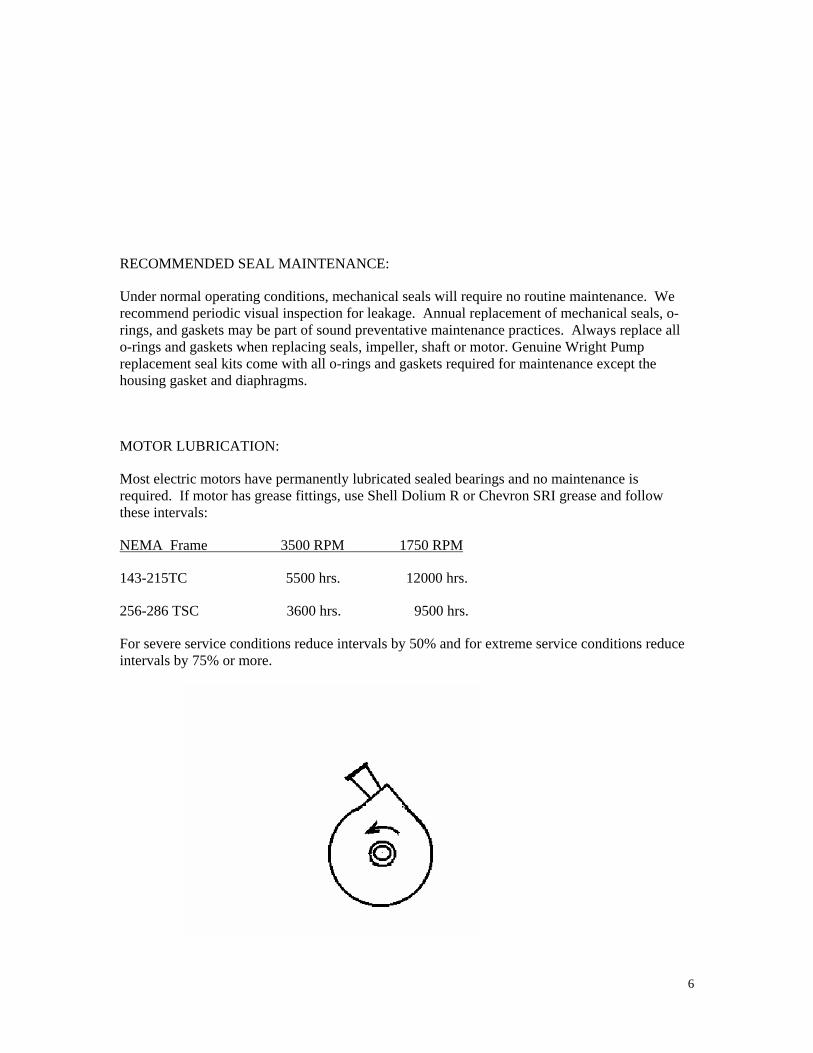
ROTATION OF PUMP MUST BE COUNTER CLOCK-WISE WHEN FACING INLET
(CLOCK-WISE FROM MOTOR FAN END) INSTALLATION Unpacking Equipment Check the contents and carefully inspect for any damage that may have occurred during shipment. Immediately report any damage to the carrier. Remove guard and rotate shaft by hand feeling and listening for any metal to metal contact noise. If you feel any restriction or hear any noise, shipping damage is likely. Follow the sections of this manual if repair of pump is necessary. Leave suction and discharge protective caps on the pump for protection until you are ready to make piping connections. Location and Installation Locate the pump in a position where the suction piping can be short and direct from the liquid source with a minimum number of bends, keeping pump accessible for maintenance when possible. Prior to installation check for level mounting surface, adequate room for maintenance, ventilation and space for motor cooling, acceptable noise level for the room environment and secure plumbing. NOTE: Pumps intended for use in hazardous environments, must use a motor with appropriate NEMA code or other safety characteristics. Failure to use the appropriate motor type may result in serious damage or injury. PIPING GUIDELINES Always follow good piping practices to ensure maximum safety, efficiency and service life from your pump. PIPING SUPPORT Both suction and discharge piping to the pump should be properly supported independent of the pump. Align piping to the pump to ensure no stress is applied to pump head.
VALVING A throttling valve to control pump volume should be installed on the discharge side of the pump. Do not install throttling valves in suction piping.

8
GENERAL GOOD PIPING PRACTICES
Avoid abrupt transitions in piping Avoid throttling valves in suction piping Keep suction lines short and direct Ensure NPSH available in the system is greater than theNPSH required by pump
Avoid air pockets and elbows to suction
Avoid sharp and non concentric transitions OTHER PIPING TIPS:
• Avoid abrupt closure of shut-off valves, this may cause hydraulic shock which can damage the pump and the system.
9
• Always use smooth transition to increase or reduce piping sizes. • Secure piping to structure – never support piping load with pump connections.
SEAL REPLACEMENT
!!! DANGER: BEGIN ALL PUMP MAINTENANCE OPERATIONS BY DISCONNECTING THE ENERGY SOURCE TO THE PUMP. OBSERVE ALL LOCK OUT/TAG OUT PROCEDURES AS OUTLINED BY ANSI Z244.1-1982 AND OSHA 1910.147 TO PREVENT ACCIDENTAL START-UP AND INJURY.
!!! DRAIN AS MUCH LIQUID AS POSSIBLE FROM THE PUMP PRIOR TO DISASSEMBLY.
All Wright Pump centrifugal pump models have both the suction and discharge in the housing, thus allowing maintenance to be performed when space is adequate by removing the housing nuts and pulling the pump and motor away from the housing without disconnecting piping (back pull out). This leaves the housing supported by the suction and discharge piping.
Remove shaft guard. Place a 5/16” or 3/8” diameter rod into the hole in the side of the pump shaft allowing the rod to rest against the flange adapter to keep the shaft from rotating while loosening the impeller nut with a 15/16” socket wrench. Protect impeller nut from scratching by applying a cloth inside socket.
Remove the impeller nut and impeller nut gasket. Remove the impeller from the shaft (NEVER PRY ON THE IMPELLER BACKPLATE AS DAMAGE MAY OCCUR).
Remove the impeller key by compressing the spring slightly. Next remove the spring and driver, and the rotating seal ring (this is easily accomplished by using a dry rag to grip each side of the seal ring and rotate back-and -forth while pulling it out, being careful not to let the seal ring scrape on the shaft threads or dropping it. If you cannot remove the rotating seal by hand, you can remove the (4) back plate bolts and carefully slide the whole back plate forward, supporting the backplate all the way until completely clear of shaft, being VERY careful not to scrape the rotating seal or stationary seal on the shaft threads.
Place the back plate on a soft surface to protect the product area from scratches and remove the (6) socket head cap screws and seal retaining ring holding the stationary seal. Remove the rear-most o-ring or gasket, stationary seal and flat gasket.
If replacing a double seal, remove the rear seal parts by pulling the rotating rear seal off of the shaft and remove the spring driver by loosening the (2) set screws and pulling it forward off the shaft.
REFER TO THE SINGLE AND DOUBLE SEAL DIAGRAMS ON PAGES 13-16.

10
Always handle seal parts without touching the polished seal faces. Reassemble with a new seal kit including new elastomers, by first wiping out the stationary seal cavity, inserting the flat gasket, stationary seal and rear most o-ring or gasket and attach seal retaining ring, securing it by cross tightening the (6) socket head cap screws until all are tight.
If replacing a double seal, insert the rear seal driver, spring and rotating seal at this time. The rear seal driver is spaced about ¼” from the shoulder of the pump shaft. There must be spring tension on the rear rotating seal by the spring for the seal to work. Tighten the (2) set screw.
Carefully slide the back plate onto the flange adapter keeping it supported and centered at all times as not to let it nick or scrape on the shaft. Secure the back plate with the (4) hex head bolts.
Install the new front seal rotating ring, seal o-ring and washer. Use a small amount of pure water to lubricate the o-ring for ease of installation. Next insert the seal spring being certain the tang of the spring fits into the notch on the seal. Next comes the seal driver which should have (2) o-rings installed one o-ring inside it and one o-ring outside on the face. Again be sure the spring tang is located in the small hole on the side of the driver.
Compress the spring with two fingers against the driver and insert the key. Install the impeller, impeller nut gasket (a little pure water will keep the impeller nut gasket in place when tightening the impeller nut) and tighten the impeller nut using a rod in the side of the shaft to hold the shaft from turning.
Be sure the housing to back plate o-ring is in place, and attach housing securing it by cross tightening the housing nuts securely.
Check for the free rotation of the shaft by turning it with your hand. If resistance is felt or if there is a rubbing sound, repeat disassembly and reassemble. If you replaced the shaft, you must check the gap between the impeller and the back plate and the shaft should be indicated within .003” TIR.
Install guard, and reconnect.
MECHANICAL SEALS MUST NEVER RUN DRY. ALWAYS FILL PUMP WITH FLUID BEFORE STARTING.
SHAFT REPLACEMENT
!!! DANGER: BEGIN ALL PUMP MAINTENANCE OPERATIONS BY DISCONNECTING THE ENERGY SOURCE TO THE PUMP. OBSERVE ALL LOCK OUT/TAG OUT PROCEDURES AS OUTLINED BY ANSI Z244.1-1982 AND OSHA 1910.147 TO PREVENT ACCIDENTAL START-UP AND INJURY.
Shaft installation should be performed without seals installed.
11
Clean and degrease motor shaft, pump shaft bore and slide the shaft locking collar onto pump shaft to the shoulder aligning the shaft collar slot with the shaft slot. (Note: follow manufacturers’ shaft collar installation instructions carefully to ensure proper connection.
1. Use collars as they are received. Do not degrease.
2. Wipe the bore clean. Do not lubricate.
3. Slide collar onto shaft to shoulder aligning collar slot with shaft slot, and snug tighten hex socket cap screw with an unplated hex wrench until a slight resistance is felt.
Slide shaft and collar assembly over motor shaft about half way down motor shaft.
Lightly tighten collar just enough to keep shaft from sliding in and out on motor shaft.
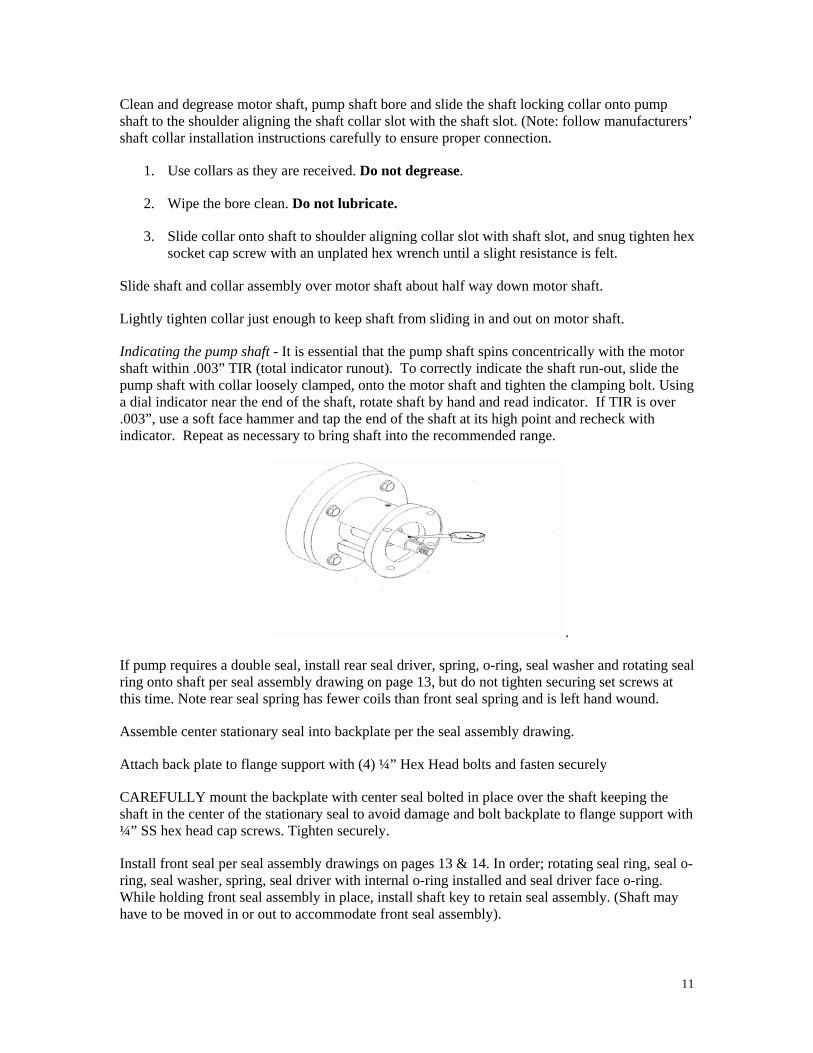
Indicating the pump shaft - It is essential that the pump shaft spins concentrically with the motor shaft within .003” TIR (total indicator runout). To correctly indicate the shaft run-out, slide the pump shaft with collar loosely clamped, onto the motor shaft and tighten the clamping bolt. Using a dial indicator near the end of the shaft, rotate shaft by hand and read indicator. If TIR is over .003”, use a soft face hammer and tap the end of the shaft at its high point and recheck with indicator. Repeat as necessary to bring shaft into the recommended range.
.
If pump requires a double seal, install rear seal driver, spring, o-ring, seal washer and rotating seal ring onto shaft per seal assembly drawing on page 13, but do not tighten securing set screws at this time. Note rear seal spring has fewer coils than front seal spring and is left hand wound.
Assemble center stationary seal into backplate per the seal assembly drawing.
Attach back plate to flange support with (4) ¼” Hex Head bolts and fasten securely
CAREFULLY mount the backplate with center seal bolted in place over the shaft keeping the shaft in the center of the stationary seal to avoid damage and bolt backplate to flange support with ¼” SS hex head cap screws. Tighten securely.
Install front seal per seal assembly drawings on pages 13 & 14. In order; rotating seal ring, seal o-ring, seal washer, spring, seal driver with internal o-ring installed and seal driver face o-ring. While holding front seal assembly in place, install shaft key to retain seal assembly. (Shaft may have to be moved in or out to accommodate front seal assembly).

12
Install impeller, impeller nut gasket (lightly lubricated with pure water) and impeller nut. Impeller nut gasket is a modified clamp type gasket that will stay in the impeller nut groove, observe that this gasket has stayed in place and not rolled out. Snug impeller nut using a 15/16”socket and ratchet while holding shaft from turning by using a bolt or rod in the 3/8” shaft hole near the shaft locking collar.
With the shaft collar only snug, tap the shaft back with a soft faced hammer until the back of the impeller is .015” to .020” from the backplate. Or if the impeller is already against the backplate, move the shaft out and away from the motor, by carefully prying on the back side of the shaft with a screwdriver until the gap is reached. NEVER PRY ON THE IMPELLER BACKPLATE.
For proper gap, install the housing (without the housing o-ring), install the housing nuts and tighten. Rotate shaft by hand and listen for impeller rubbing. If shaft does not turn or rubbing sound is clearly heard, remove housing and readjust by moving shaft in or out as needed to eliminate rubbing. Note: dry seals will emit a slight high pitched squeak when rotating shaft…this is normal and should not be mistaken for impeller rubbing.
Impeller should be about .015-.020” from the housing when finally gapped.
Tighten impeller nut very securely 70-80 ft-lb. using steady/even force with a ratchet and 15/16” socket. NEVER STRIKE THE RATCHET OR WRENCH OR APPLY JERKING FORCE AS DEFLECTION OF THE SHAFT MAY CAUSE SEAL TO BREAK.
Install housing o-ring and secure to back plate with housing nuts 50 ft. lb.
The last step in securing the pump shaft to the motor shaft is to tighten the collar. WRING COLLAR INTO FINAL POSITION BY LOOSENING THE COLLAR JUST ENOUGH TO MOVE IT ABOUT 20 DEGREES OR MORE AND TIGHTEN VERY SECURELY ALIGNING THE COLLAR SLOT WITH THE SLOT IN THE PUMP SHAFT, USING THE TORQUE RATING CHART BELOW:
Clamp Screw Seating Torque (lb-in)
¼”-28 (56C-184TC) 225
5/16”-24 (213TC-256TC 350
Slide rear seal driver ring forward toward pump to apply spring pressure to seal faces (approximately ¼”-3/8" from shaft shoulder). Lock in place by tightening the (2) set screws.
13
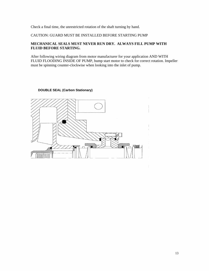
Check a final time, the unrestricted rotation of the shaft turning by hand.
CAUTION: GUARD MUST BE INSTALLED BEFORE STARTING PUMP
MECHANICAL SEALS MUST NEVER RUN DRY. ALWAYS FILL PUMP WITH FLUID BEFORE STARTING.
After following wiring diagram from motor manufacturer for your application AND WITH FLUID FLOODING INSIDE OF PUMP, bump start motor to check for correct rotation. Impeller must be spinning counter-clockwise when looking into the inlet of pump.
DOUBLE SEAL (Carbon Stationary)

14
REFER TO YOUR PARTICULAR SEAL FOR PART NUMBERS AND DESCRIPTIONS
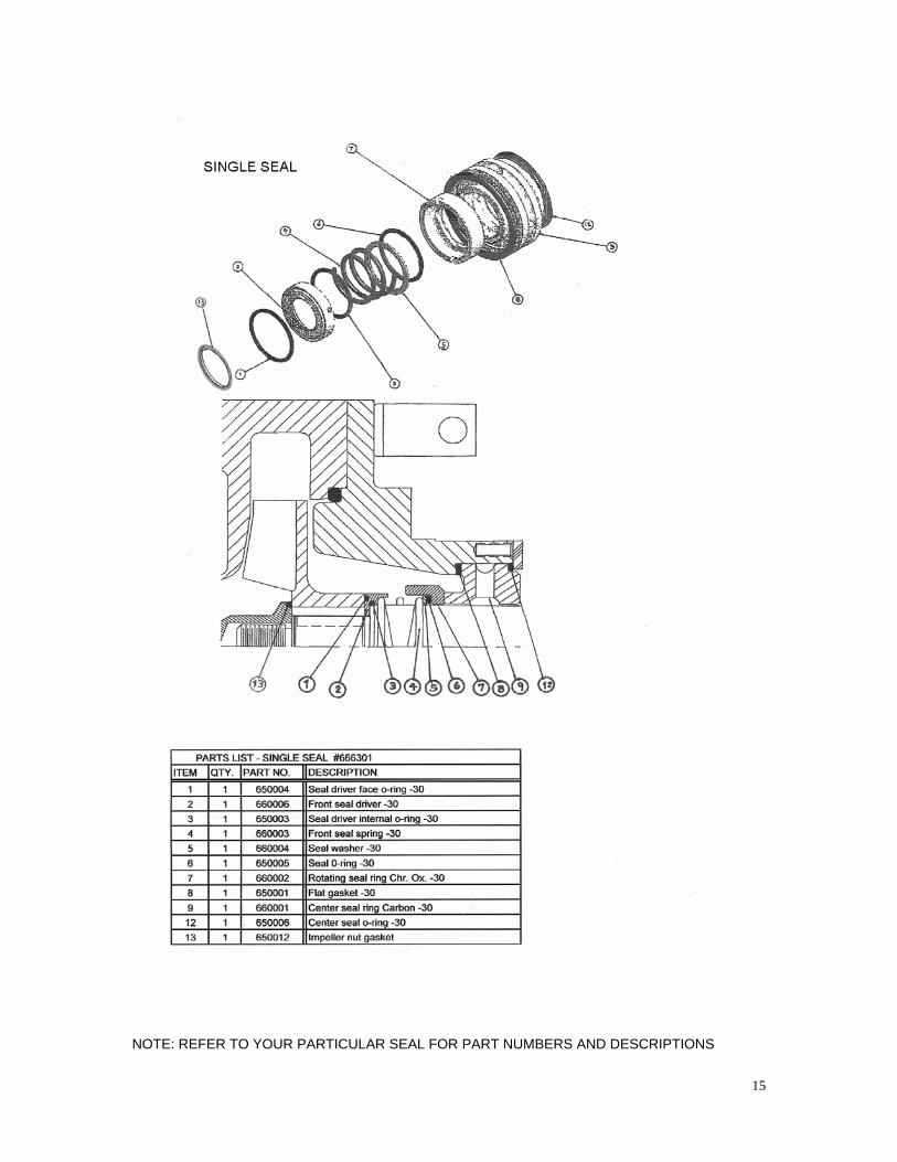
15
NOTE: REFER TO YOUR PARTICULAR SEAL FOR PART NUMBERS AND DESCRIPTIONS

16

17

18
SINGLE AND DOUBLE SEAL FLUSHING WITH THE SOFTSTERILE™ SEAL FLUSHING SYSTEM (Pat. Pending)
Viewed from back of pump The interior portion of the pump (impeller vanes and casing) may have pressures up to 140 PSI, and the front seal area (behind the impeller) pressure will be significantly less without a front seal flush hole. Wright Pump has developed a Patent Pending internal front seal flush that allows a little recirculation of the product from the area of the impeller tips where the product velocity is the highest. This straight-line fully drainable passage allows the single or front seal to be continuously flushed. The recirculation back into the pump casing is accomplished by holes through the impeller and the small gap between the impeller and back plate. (See diagram and photo).
19
Flushing of the double (rear) seal is done internally by using a very small amount of product liquid. On double seal arrangements, the seal room has an additional passage whereby high pressure fluid is directed to a diaphragm valve that is the gate-keeper. This valve when open, and with fine adjustment of the needle valve ensures seal flushing liquid is present to drain. The double seal flushing is always from high pressure to low pressure (atmosphere) and cannot re-enter the pump casing. ADJUSTING SEAL FLUSH WATER FLOW ON SOFTSTERILE™ DOUBLE SEAL STARTING UP PUMP - Be sure liquid is inside pump, prior to start up. Pump seals must never run dry. Open the seal flush manual diaphragm valve (located near the top of the backplate) one full turn or more by turning counterclockwise. Open needle valve slightly until a flow of 1-2 GPH is steady to the drain. Pump can now be started. During the first few minutes of pump operation, check the seal flush flow rate to the drain to ensure a minimum of 1-2 GPH at all times, seal flush flow rates may be higher, but in no cases should the flush liquid go below 1 GPH. Shutting down the pump – Cut power to the pump and closing the diaphragm valve only will stop the seal flush flow. The needle valve need not be closed.
20
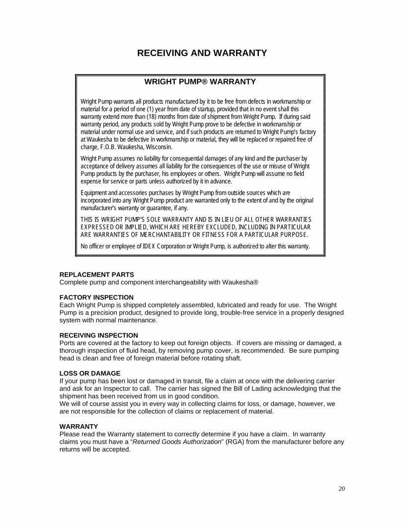
RECEIVING AND WARRANTY REPLACEMENT PARTS Complete pump and component interchangeability with Waukesha® FACTORY INSPECTION Each Wright Pump is shipped completely assembled, lubricated and ready for use. The Wright Pump is a precision product, designed to provide long, trouble-free service in a properly designed system with normal maintenance. RECEIVING INSPECTION Ports are covered at the factory to keep out foreign objects. If covers are missing or damaged, a thorough inspection of fluid head, by removing pump cover, is recommended. Be sure pumping head is clean and free of foreign material before rotating shaft. LOSS OR DAMAGE If your pump has been lost or damaged in transit, file a claim at once with the delivering carrier and ask for an Inspector to call. The carrier has signed the Bill of Lading acknowledging that the shipment has been received from us in good condition. We will of course assist you in every way in collecting claims for loss, or damage, however, we are not responsible for the collection of claims or replacement of material. WARRANTY Please read the Warranty statement to correctly determine if you have a claim. In warranty claims you must have a “Returned Goods Authorization” (RGA) from the manufacturer before any returns will be accepted.
WRIGHT PUMP® WARRANTY
Wright Pump warrants all products manufactured by it to be free from defects in workmanship or material for a period of one (1) year from date of startup, provided that in no event shall this warranty extend more than (18) months from date of shipment from Wright Pump. If during said warranty period, any products sold by Wright Pump prove to be defective in workmanship or material under normal use and service, and if such products are returned to Wright Pump’s factory at Waukesha to be defective in workmanship or material, they will be replaced or repaired free of charge, F.O.B. Waukesha, Wisconsin.
Wright Pump assumes no liability for consequential damages of any kind and the purchaser by acceptance of delivery assumes all liability for the consequences of the use or misuse of Wright Pump products by the purchaser, his employees or others. Wright Pump will assume no field expense for service or parts unless authorized by it in advance.
Equipment and accessories purchases by Wright Pump from outside sources which are incorporated into any Wright Pump product are warranted only to the extent of and by the original manufacturer’s warranty or guarantee, if any.
THIS IS WRIGHT PUMP’S SOLE WARRANTY AND IS IN LIEU OF ALL OTHER WARRANTIES EXPRESSED OR IMPLIED, WHICH ARE HEREBY EXCLUDED, INCLUDING IN PARTICULAR ARE WARRANTIES OF MERCHANTABILITY OR FITNESS FOR A PARTICULAR PURPOSE.
No officer or employee of IDEX Corporation or Wright Pump, is authorized to alter this warranty.