WREN Hydraulic Torque Wrench Manual - LOW
20
LOW 1 WREN HYDRAULIC TORQUE WRENCHES LOW SERIES OPERATION AND MAINTENANCE MANUAL FOR WREN 2LOW, 4LOW, 8LOW, 14LOW and 30LOW LOW PROFILE HYDRAULIC TORQUE WRENCHES Series 2LOW, 4LOW, 8LOW, 14LOW and 30LOW Low Profile Hydraulic Torque Wrenches are designed for installing and removing large bolts having minimal wrench clearance requiring precise high torque during bolt makeup and maximum torque for bolt breakout. It is necessary to read and understand this Operation and Maintenance Manual when using WREN Hydraulic Torque Wrenches. The use of other than genuine WREN replacement parts may result in safety hazards, decreased tool performance, increased maintenance and may invalidate warranty. Read this manual carefully before operating tool.
description
Hytorc for bolt tightening for various size of bolt and nuts
Transcript of WREN Hydraulic Torque Wrench Manual - LOW
LOW
1
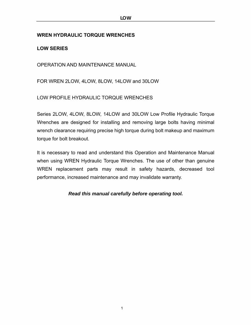
WREN HYDRAULIC TORQUE WRENCHES
LOW SERIES
OPERATION AND MAINTENANCE MANUAL
FOR WREN 2LOW, 4LOW, 8LOW, 14LOW and 30LOW
LOW PROFILE HYDRAULIC TORQUE WRENCHES
Series 2LOW, 4LOW, 8LOW, 14LOW and 30LOW Low Profile Hydraulic Torque
Wrenches are designed for installing and removing large bolts having minimal
wrench clearance requiring precise high torque during bolt makeup and maximum
torque for bolt breakout. It is necessary to read and understand this Operation and Maintenance Manual
when using WREN Hydraulic Torque Wrenches. The use of other than genuine
WREN replacement parts may result in safety hazards, decreased tool
performance, increased maintenance and may invalidate warranty.
Read this manual carefully before operating tool.
LOW
2
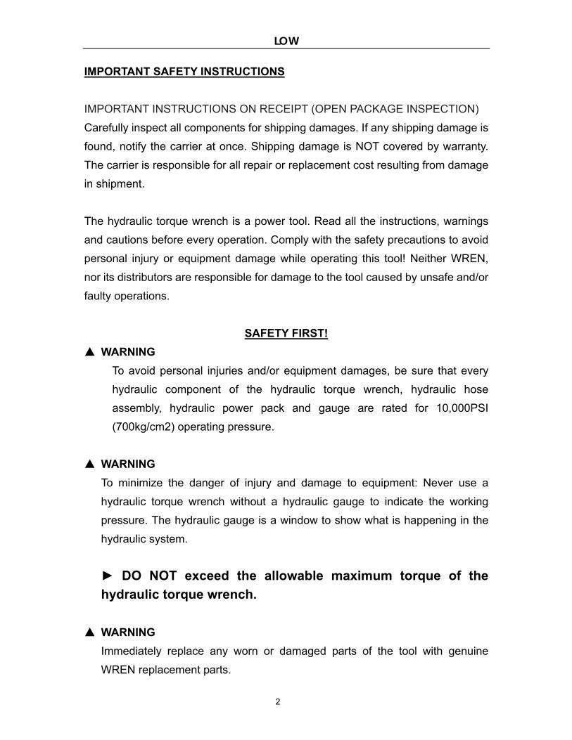
IMPORTANT SAFETY INSTRUCTIONS
IMPORTANT INSTRUCTIONS ON RECEIPT (OPEN PACKAGE INSPECTION)
Carefully inspect all components for shipping damages. If any shipping damage is
found, notify the carrier at once. Shipping damage is NOT covered by warranty.
The carrier is responsible for all repair or replacement cost resulting from damage
in shipment.
The hydraulic torque wrench is a power tool. Read all the instructions, warnings
and cautions before every operation. Comply with the safety precautions to avoid
personal injury or equipment damage while operating this tool! Neither WREN,
nor its distributors are responsible for damage to the tool caused by unsafe and/or
faulty operations.
SAFETY FIRST!
▲ WARNING
To avoid personal injuries and/or equipment damages, be sure that every
hydraulic component of the hydraulic torque wrench, hydraulic hose
assembly, hydraulic power pack and gauge are rated for 10,000PSI
(700kg/cm2) operating pressure.
▲ WARNING
To minimize the danger of injury and damage to equipment: Never use a
hydraulic torque wrench without a hydraulic gauge to indicate the working
pressure. The hydraulic gauge is a window to show what is happening in the
hydraulic system.
► DO NOT exceed the allowable maximum torque of the
hydraulic torque wrench.
▲ WARNING
Immediately replace any worn or damaged parts of the tool with genuine
WREN replacement parts.
LOW
3
▲ CAUTION
All of the hydraulic torque wrench components of the tool are kept away from
excessive heat, flame, moving machine parts, sharp edges and chemicals.
▲ CAUTION
Reduce damage to the hydraulic hose assembly by avoiding sharp bends and
kinks when routing the hydraulic hose assembly. Using a bent or kinked
hydraulic hose assembly will cause severe back-pressure. Also, sharp bends
and kinks will internally damage the hose leading to premature failure. A
kinked or damaged hydraulic hose assembly should be replaced immediately.
▲ CAUTION
DO NOT drop heavy objects, crush, or drive over the hydraulic hose assembly.
A sharp impact may cause internal damage to the hose wire strands. Applying
pressure to a damaged hose may cause it to rupture. A crushed hydraulic
hose assembly should be replaced immediately.
▲ CAUTION
Avoid high temperature exposure to the hydraulic hose assembly.
► ALWAYS INSPECT THE HYDRAULIC HOSE ASSEMBLY FOR
DAMAGE AND WEAR BEFORE IT IS USED.
▲ WARNING
To avoid personal injuries, equipment damage and/or warranty invalidation:
DO NOT:
Remove the shroud from the hydraulic torque wrench.
Modify any component of the hydraulic torque wrench.
Adjust the hydraulic torque wrench safety relief valve located
inside the swivel couplings.
LOW
4
▲ CAUTION
The incorrect system connection may cause failure and injury. Before
connecting the hydraulic torque wrench and hydraulic hose assembly to the
assembled power pack, make sure the hydraulic torque wrench swivel
couplings, hose couplings and hydraulic power pack couplings are clean and
free of debris.
► LOOSE OR DIRTY COUPLERS WILL CAUSE TOOL NOT TO OPERATE
PROPERLY.
PROPER SAFETY ATTIRE
When operating hydraulic equipment, use proper safety equipment and clothing.
Consult with your company’s safety representative to obtain this information.
OPERATION SECTION
Reference
The Operation and Maintenance Manual of the electric or air powered torque
wrench pump.
Hydraulic Torque Wrench Set Up
Connect the LOW Wrench Head to the selected hex ratchet link. Then, connect
the hydraulic power pack with the proper twin line hydraulic hose assembly
making sure all connections are proper and snug.
Preparation
1. Make certain of the size of the nut or bolt head, material, strength grade and
determine the desired torque.
Appendix I, which is presented as a guideline for comparison only, gives
typical torque values specified for the most commonly encountered fasteners.
Torque sequence may vary from manufacturer to manufacturer and even
LOW
5
within individual factories, depending on the gasket material etc.
►Always abide by the manufacturers/engineers procedures.
2. Determine the torque value needed and then determine the corresponding
pressure of the hydraulic power pack. This can be found in the Pressure
-Torque Conversion Chart that was provided with the hydraulic torque wrench.
You may also find this chart on the web @ www.wrentools.com
3. Inspect the hydraulic torque wrench set. Connect the hydraulic torque wrench,
hydraulic hose assembly and the hydraulic power pack in to a hydraulic circuit.
Ensure all hydraulic connections are securely connected. Verify that the
hydraulic hose assembly is not kinked, crushed or damaged.
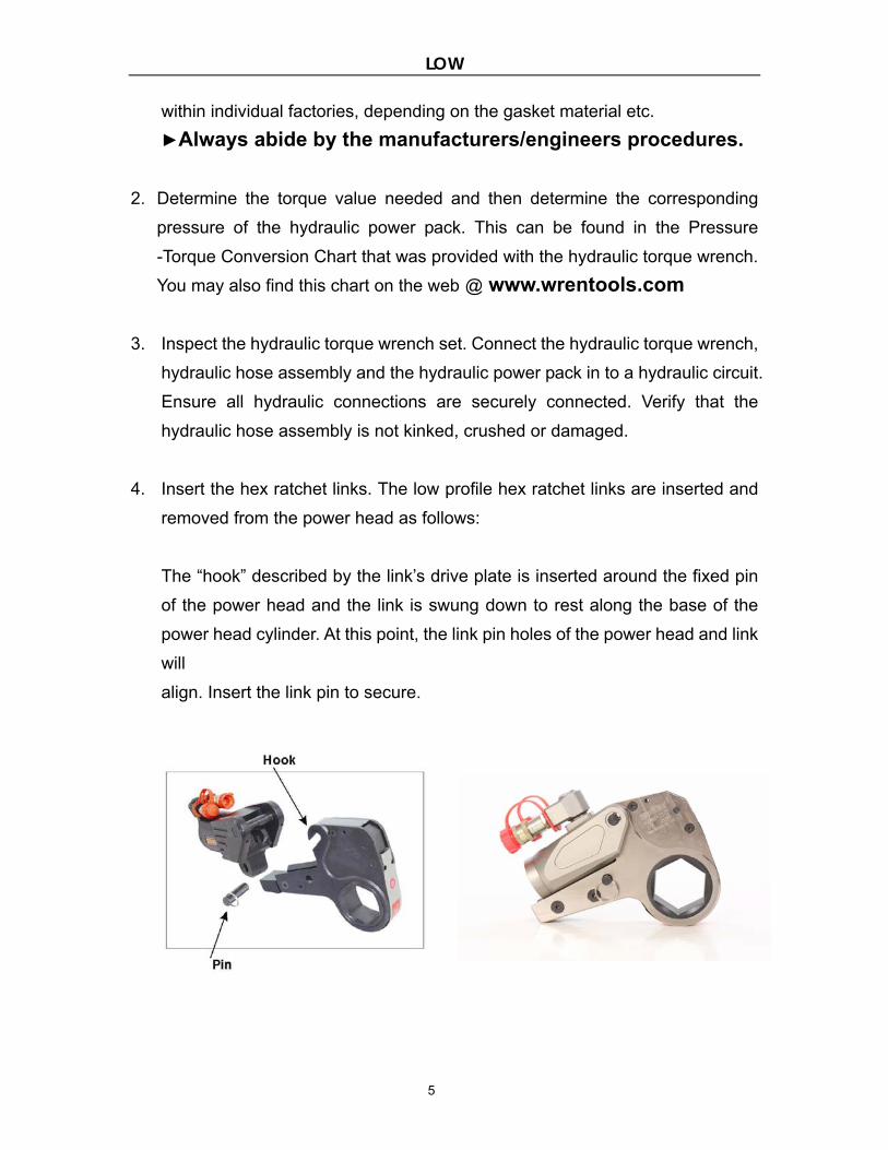
4. Insert the hex ratchet links. The low profile hex ratchet links are inserted and
removed from the power head as follows:
The “hook” described by the link’s drive plate is inserted around the fixed pin
of the power head and the link is swung down to rest along the base of the
power head cylinder. At this point, the link pin holes of the power head and link
will
align. Insert the link pin to secure.

LOW
6
5. Setting for tightening or loosening the nut:
The position of the tool relative to the nut determines whether the action will
tighten or loosen the nut. The power stroke of the piston rod will always turn
the hex ratchet toward the shroud. The nut turns clockwise for tightening
and counterclockwise for loosening.
6. Connecting the hydraulic torque wrench:
The hydraulic torque wrench and hydraulic power pack are connected by a
10,000 PSI operation pressure twin line hydraulic hose assembly.
IMPORTANT
To avoid hydraulic torque wrench malfunction:
► DO NOT reverse connectors.
DO NOT tamper with the set screw in the swivel assembly. (It is factory preset
for safety purposes and adjustments should only be made by trained personnel.)
LOW
7
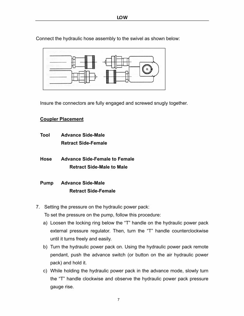
Connect the hydraulic hose assembly to the swivel as shown below:
Insure the connectors are fully engaged and screwed snugly together.
Coupler Placement
Tool Advance Side-Male
Retract Side-Female
Hose Advance Side-Female to Female
Retract Side-Male to Male
Pump Advance Side-Male
Retract Side-Female
7. Setting the pressure on the hydraulic power pack:
To set the pressure on the pump, follow this procedure:
a) Loosen the locking ring below the “T” handle on the hydraulic power pack
external pressure regulator. Then, turn the “T” handle counterclockwise
until it turns freely and easily.
b) Turn the hydraulic power pack on. Using the hydraulic power pack remote
pendant, push the advance switch (or button on the air hydraulic power
pack) and hold it.
c) While holding the hydraulic power pack in the advance mode, slowly turn
the “T” handle clockwise and observe the hydraulic power pack pressure
gauge rise.
LOW
8
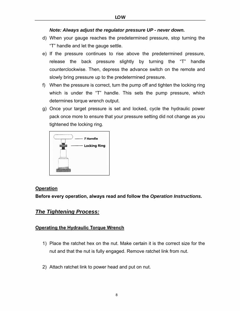
Note: Always adjust the regulator pressure UP - never down.
d) When your gauge reaches the predetermined pressure, stop turning the
“T” handle and let the gauge settle.
e) If the pressure continues to rise above the predetermined pressure,
release the back pressure slightly by turning the “T” handle
counterclockwise. Then, depress the advance switch on the remote and
slowly bring pressure up to the predetermined pressure.
f) When the pressure is correct, turn the pump off and tighten the locking ring
which is under the “T” handle. This sets the pump pressure, which
determines torque wrench output.
g) Once your target pressure is set and locked, cycle the hydraulic power
pack once more to ensure that your pressure setting did not change as you
tightened the locking ring.
Operation
Before every operation, always read and follow the Operation Instructions.
The Tightening Process:
Operating the Hydraulic Torque Wrench
1) Place the ratchet hex on the nut. Make certain it is the correct size for the
nut and that the nut is fully engaged. Remove ratchet link from nut.
2) Attach ratchet link to power head and put on nut.
LOW
9
3) Position the reaction surface against an adjacent nut, flange or solid
system component. Make certain that there is clearance for the hydraulic
hose assembly, swivels and couplings.
4) Do not allow the tool to react against the hydraulic hose assembly,
swivels or couplings.
5) Turn the hydraulic power pack on and preset the pressure for the correct
torque setting, depress the remote control advance button to advance the
piston rod. If the piston rod end did not engage the drive pin in the ratchet
link when the link was joined to the power head, it will engage the pin
automatically during the first advance stroke.
6) Before applying pressure to the hydraulic wrench, check to make sure all
body parts are safely out of harm’s way. This tool has massive power
and can cause bodily damage.
7) When hydraulic pressure is applied to the hydraulic torque wrench the
reaction surface of the wrench will move against the reaction point and the
nut will begin to turn. Once the piston reaches the end of its stroke, release
the remote button and the tool will automatically retract the piston.
8) Continue this cycling operation of advance and retract until the nut is no
longer turning and the hydraulic power pack’s gauge reaches the preset
pressure. The piston rod will automatically retract when the remote control
button is released and the operator will hear an audible “click” as the tool
resets itself.
9) Continue to cycle the tool until it “stalls” and the preset PSI/Torque has
been attained.
LOW
10
IMPORTANT: The reading of full preset pressure after the cylinder is
extended DOES NOT INDICATE that this pressure (torque) is applied
to the bolt/nut. It only indicates that the cylinder is fully extended and
cannot turn the ratchet further until the tool automatically resets
itself.
10) Once the nut stops rotating, cycle the tool one last time to achieve total
torque.
IMPORTANT: ALWAYS ATTEMPT ONE FINAL CYCLE TO INSURE THE
“STALL” POINT HAS BEEN REACHED.
“Locked-On”
Should the hydraulic torque wrench be “locked-on” after the final cycle, push
the remote control advance button once more (to build pressure) and while
maintaining this pressure, push the accuracy assurance lever (located on the
front of the ratchet link). Release the remote control advance button, while
continuing to push down on the accuracy assurance lever (this will allow the
hydraulic torque wrench to be removed easily).
The Loosening Process:
1. Set the pump to 10,000 PSI. Change the tool to the loosening mode,
assuring the reaction surface abuts squarely on a solid reaction point.
2. Press and hold hydraulic power pack’s remote control advance button.
Pressure will decrease as the nut begins to turn. As the cylinder extends fully,
you will hear an audible “click”.
3. Release the remote control advance button and the hydraulic torque
wrench’s cylinder automatically retracts, at which time you again hear the
audible “click”.
LOW
11
4. Repeat this process until the fastener can be removed by hand.
NOTE: IF THE NUT/BOLT DOES NOT LOOSEN WITH THE ABOVE
PROCEDURES, IT IS AN INDICATION THAT YOU REQUIRE A LARGER
HYDRAULIC TORQUE WRENCH TO LOOSEN THE NUT/BOLT.
After the operation
1. Upon completing the project; turn off the power to the hydraulic power pack.
2. Disconnect all the coupler connections between the hydraulic torque wrench
and hydraulic hose assembly, and then the hose assembly and hydraulic
power pack.
3. Loosen the locking ring below the “T” handle on the hydraulic power pack
external pressure regulator. Then, turn the “T” handle counterclockwise until it
turns freely and easily.
4. When not in use, tools and accessories should be properly stored to avoid
damage.
MAINTENANCE SECTION
Preventative Maintenance
Lubrication
All moving parts should be periodically coated with a good quality lubricant.
Under harsh environmental conditions, cleaning and lubricating should be
performed more frequently.
Hydraulic Hose Assembly
The hydraulic hose assembly should be inspected for cracks, burns, kinks,

LOW
12
crush spots and leaks after each job. Hydraulic fittings can become plugged
with dirt and should be flushed periodically. If any damage to the hydraulic
hose assembly is found, the hydraulic hose assembly should be replaced
immediately.
Connectors
Hydraulic coupler fittings should be kept clean and not allowed to be dragged
on the ground or floor. Even small particles of dirt can cause the internal
valves to malfunction.
Cylinder Seals
If the cylinder requires disassembly, it is recommended that the cylinder seals
be replaced at the same time. Seal kits are readily available.
Structural Members
All structural parts on the tool should be inspected periodically to determine if
there are any cracks, chips or deformities. If so, immediate replacement is
required.
▪ Calibration
Calibration should be performed at least once a year on all hydraulic torque
wrenches and gauges.
TROUBLE-SHOOTING CHART
SYSTEM PROBABLE CAUSE REMEDY
Cylinder will not advance 1. Couplers loose or damaged
2. Dirt in direction-control valve on pumping unit
3. Couplers not mated securely.
1. Tighten
2. Disassemble and clean
3. Tighten
Cylinder will not retract See above See above
Cylinder will not build up
pressure
1. Piston seal leaks.
2. Pump coupling is broken not mated properly or
coupler is defective
3. Gauge
1. Replace seals
2. Replace coupling
3. Replace gauge
Cylinder leaks Safety release valve on cylinder Replace cylinder seals and packing
Cylinder operates backwards Disconnects are reversed on hoses, pump, or tool Reverse disconnects on tool
LOW
13
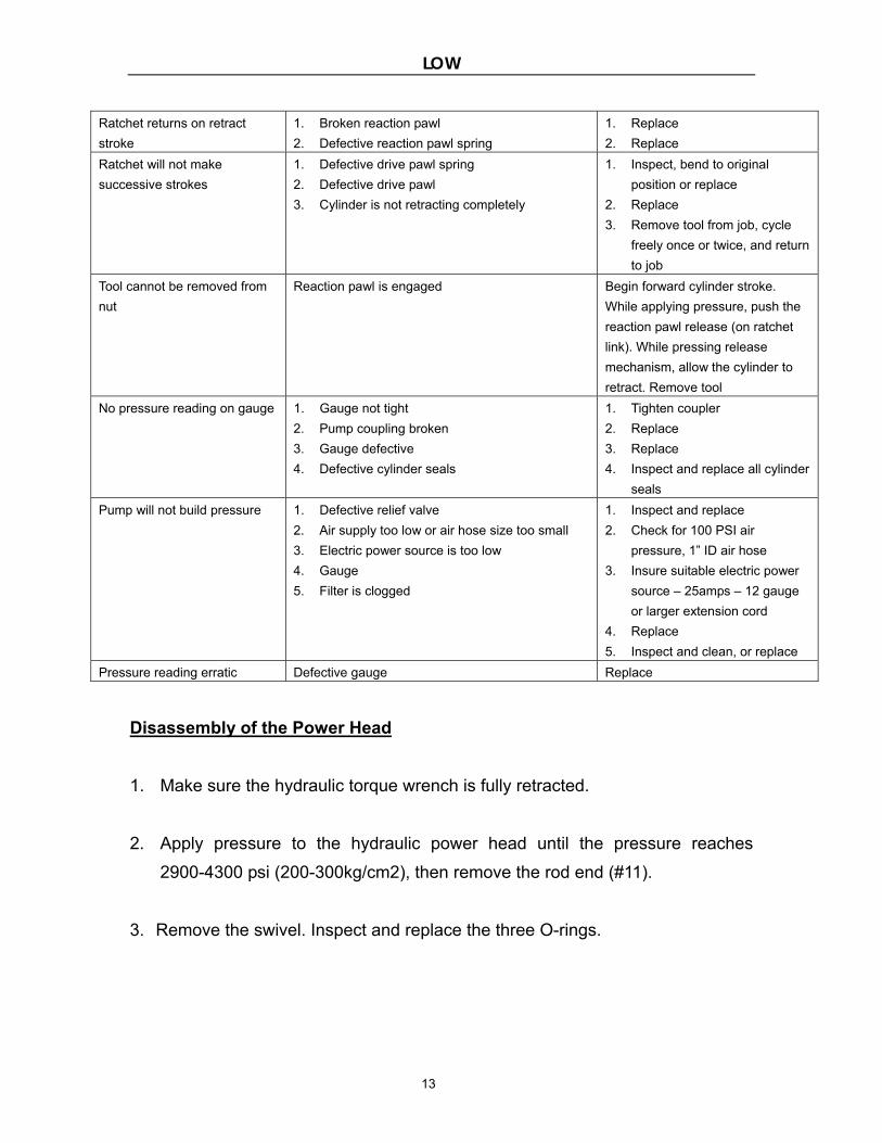
Ratchet returns on retract
stroke
1. Broken reaction pawl
2. Defective reaction pawl spring
1. Replace
2. Replace
Ratchet will not make
successive strokes
1. Defective drive pawl spring
2. Defective drive pawl
3. Cylinder is not retracting completely
1. Inspect, bend to original
position or replace
2. Replace
3. Remove tool from job, cycle
freely once or twice, and return
to job
Tool cannot be removed from
nut
Reaction pawl is engaged Begin forward cylinder stroke.
While applying pressure, push the
reaction pawl release (on ratchet
link). While pressing release
mechanism, allow the cylinder to
retract. Remove tool
No pressure reading on gauge 1. Gauge not tight
2. Pump coupling broken
3. Gauge defective
4. Defective cylinder seals
1. Tighten coupler
2. Replace
3. Replace
4. Inspect and replace all cylinder
seals
Pump will not build pressure 1. Defective relief valve
2. Air supply too low or air hose size too small
3. Electric power source is too low
4. Gauge
5. Filter is clogged
1. Inspect and replace
2. Check for 100 PSI air
pressure, 1” ID air hose
3. Insure suitable electric power
source – 25amps – 12 gauge
or larger extension cord
4. Replace
5. Inspect and clean, or replace
Pressure reading erratic Defective gauge Replace
Disassembly of the Power Head
1. Make sure the hydraulic torque wrench is fully retracted.
2. Apply pressure to the hydraulic power head until the pressure reaches
2900-4300 psi (200-300kg/cm2), then remove the rod end (#11).
3. Remove the swivel. Inspect and replace the three O-rings.
LOW
14
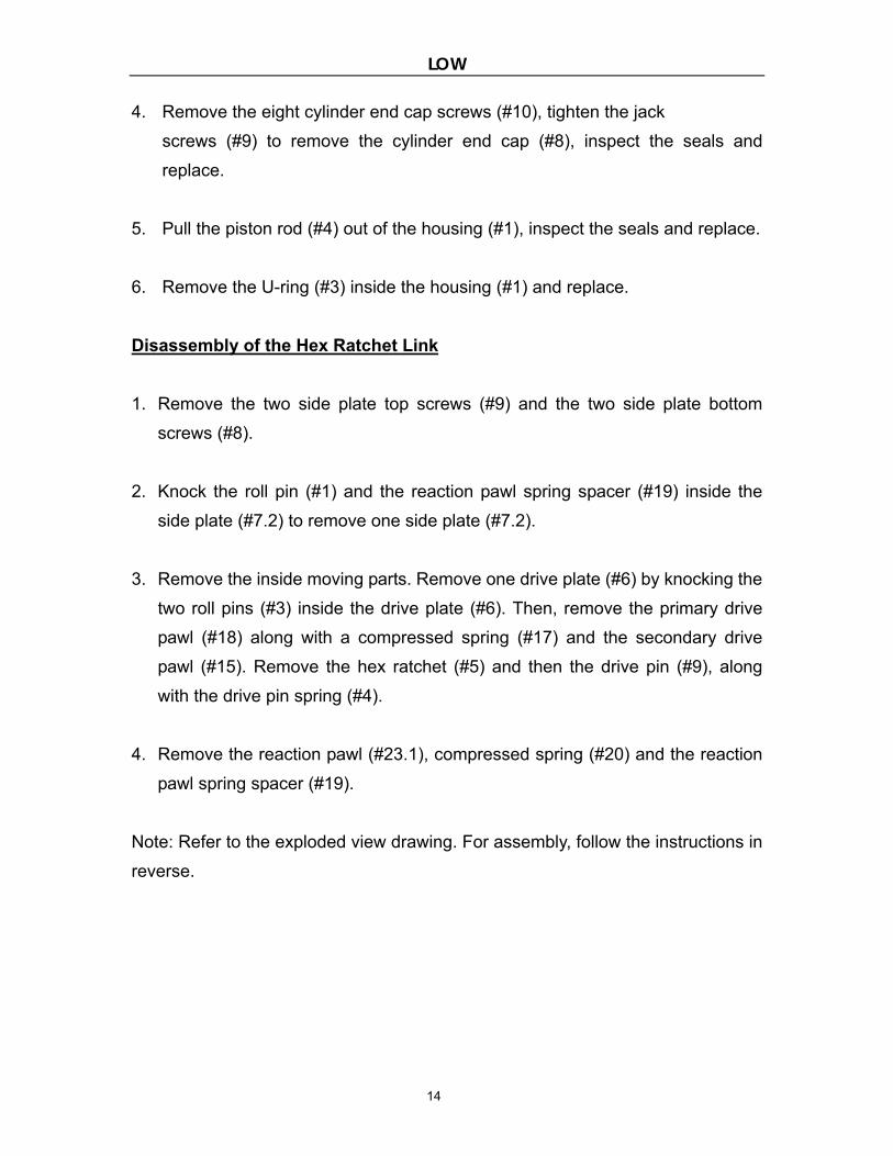
4. Remove the eight cylinder end cap screws (#10), tighten the jack
screws (#9) to remove the cylinder end cap (#8), inspect the seals and
replace.
5. Pull the piston rod (#4) out of the housing (#1), inspect the seals and replace.
6. Remove the U-ring (#3) inside the housing (#1) and replace.
Disassembly of the Hex Ratchet Link
1. Remove the two side plate top screws (#9) and the two side plate bottom
screws (#8).
2. Knock the roll pin (#1) and the reaction pawl spring spacer (#19) inside the
side plate (#7.2) to remove one side plate (#7.2).
3. Remove the inside moving parts. Remove one drive plate (#6) by knocking the
two roll pins (#3) inside the drive plate (#6). Then, remove the primary drive
pawl (#18) along with a compressed spring (#17) and the secondary drive
pawl (#15). Remove the hex ratchet (#5) and then the drive pin (#9), along
with the drive pin spring (#4).
4. Remove the reaction pawl (#23.1), compressed spring (#20) and the reaction
pawl spring spacer (#19).
Note: Refer to the exploded view drawing. For assembly, follow the instructions in
reverse.

LOW
15
APPENDIX I
LOW
16
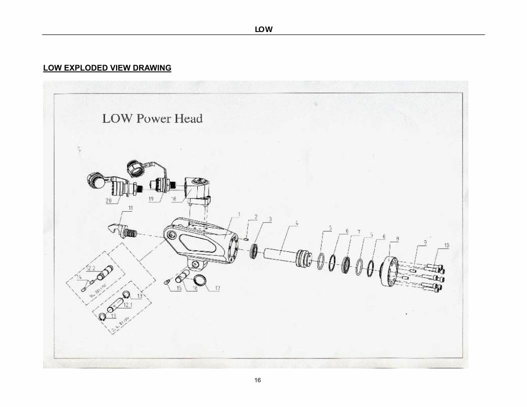
LOW EXPLODED VIEW DRAWING
LOW
17
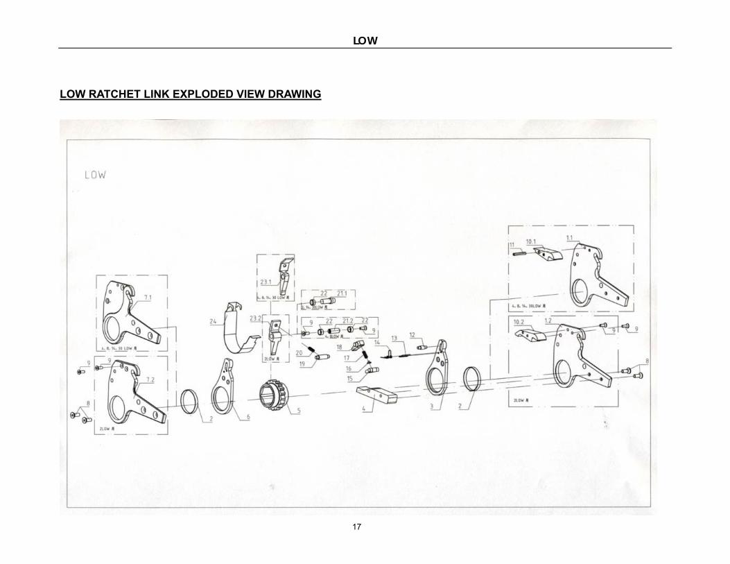
LOW RATCHET LINK EXPLODED VIEW DRAWING
LOW
18
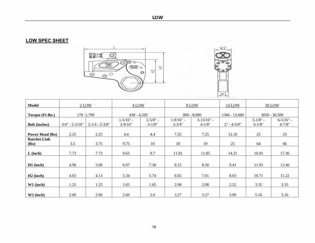
LOW SPEC SHEET
Model 2 LOW 4 LOW 8 LOW 14 LOW 30 LOW
Torque (Ft-lbs.) 170 -1,700 430 - 4,320 800 - 8,000 1366 - 13,660 3050 - 30,500
Bolt (inches) 3/4" - 2-3/16" 2-1/4 - 2-3/8" 1-5/16" - 2-9/16"
2-5/8" - 3-1/8"
1-9/16" - 3-3/4"
3-13/16" - 4-1/8" 2" - 4-5/8"
3-1/8" - 6-1/8"
6-5/16" - 6-7/8"
Power Head (lbs) 2.25 2.25 4.4 4.4 7.25 7.25 12.10 25 25 Ratchet Link (lbs) 3.5 3.75 9.75 10 18 19 25 64 66
L (inch) 7.73 7.73 9.65 9.7 11.81 11.85 14.21 16.93 17.36
H1 (inch) 4.96 5.06 6.97 7.36 8.15 8.50 9.41 11.93 12.40
H2 (inch) 4.03 4.13 5.34 5.74 6.65 7.01 8.03 10.71 11.22
W1 (inch) 1.25 1.25 1.65 1.65 2.08 2.08 2.52 3.35 3.35
W2 (inch) 2.00 2.00 2.60 2.6 3.27 3.27 3.89 5.16 5.16
LOW
19
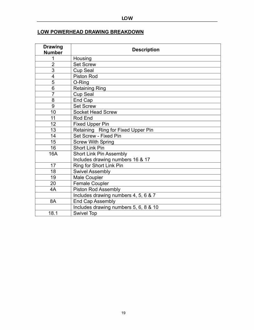
LOW POWERHEAD DRAWING BREAKDOWN
Drawing Number
Description
1 Housing 2 Set Screw 3 Cup Seal 4 Piston Rod 5 O-Ring 6 Retaining Ring 7 Cup Seal 8 End Cap 9 Set Screw 10 Socket Head Screw 11 Rod End 12 Fixed Upper Pin 13 Retaining Ring for Fixed Upper Pin 14 Set Screw - Fixed Pin 15 Screw With Spring 16 Short Link Pin
16A Short Link Pin Assembly Includes drawing numbers 16 & 17
17 Ring for Short Link Pin 18 Swivel Assembly 19 Male Coupler 20 Female Coupler 4A Piston Rod Assembly
Includes drawing numbers 4, 5, 6 & 7 8A End Cap Assembly
Includes drawing numbers 5, 6, 8 & 10 18.1 Swivel Top
LOW
20
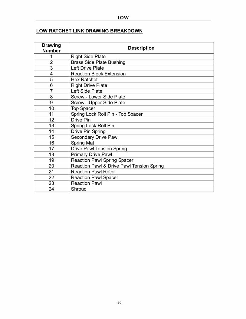
LOW RATCHET LINK DRAWING BREAKDOWN
Drawing Number
Description
1 Right Side Plate 2 Brass Side Plate Bushing 3 Left Drive Plate 4 Reaction Block Extension 5 Hex Ratchet 6 Right Drive Plate 7 Left Side Plate 8 Screw - Lower Side Plate 9 Screw - Upper Side Plate 10 Top Spacer 11 Spring Lock Roll Pin - Top Spacer 12 Drive Pin 13 Spring Lock Roll Pin 14 Drive Pin Spring 15 Secondary Drive Pawl 16 Spring Mat 17 Drive Pawl Tension Spring 18 Primary Drive Pawl 19 Reaction Pawl Spring Spacer 20 Reaction Pawl & Drive Pawl Tension Spring 21 Reaction Pawl Rotor 22 Reaction Pawl Spacer 23 Reaction Pawl 24 Shroud