
WQ-truss design according to Russian and European Standards
79
WQ-truss design according to Russian and European Standards Bachelor’s thesis Construction engineering Visamäki, Spring 2015 Maria Solodovnikova
Transcript of WQ-truss design according to Russian and European Standards

WQ-truss design according to Russian and European
Standards
Bachelor’s thesis
Construction engineering
Visamäki, Spring 2015
Maria Solodovnikova

ABSTRACT
Unit VisämäkiDegree Programme Construction EngineeringOption Steel design
Author Maria Solodovnikova Year 2015
Subject of Bachelor’s thesis WQ-truss design according to Russian and Eu-ropean standards
The purpose of this Bachelor’s thesis was to compare the Russian and Eu-ropean norms for the design of a new solution, called WQ-truss system.The aim was to provide detailed information about the Russian and Euro-pean Standards and design methods to make things clear for foreign de-signers. The study was conducted using the latest versions of the RussianStandards and Eurocodes.
In addition, the main idea was to show the advantages of the WQ-truss andthe calculation methods of the system based on the Russian and EuropeanStandards. This article did not cover joint design which can be developedand researched in the future.
The comparison was based on the results of the calculations which wereperformed using Autodesk Robot Professional. The capacity usage ratioswere compared. It was concluded that design according to Eurocodes al-lows using plastic capacity of steel, uses different safety factors and meth-ods in general. This fact is influenced results in general.
Literature concerning the Russian and European norms helped to imple-ment the research. Also, information about WQ-truss from websites ofmanufacturers was used.
Keywords WQ-truss, Russian standard, SNiP
Pages 72p. + appendices 0 p.

FOREWORD
This Bachelor’s thesis was written in order to sum up the results of studying for a Bach-elor’s degree in the Degree Programme in Construction engineering at Häme Universityof Applied Sciences and was inspired by Pöyry Oy.
The topic, WQ-truss design according to Russian and European standards, was selectedby Pöyry Oy in purpose to develop Russian projects and also introduce new solutions inthe design process. I would like to express my gratitude to this company for funding thisproject.
I would like to thank my supervisor Aleksi Pöyhönen for providing initial data and forall comments and valuable advices during the thesis writing process. The literature andpractical information gave a fundamental understanding of such a modern solution asthe WQ-truss system. Additionally, I am grateful for explaining the basis of calculationmethods according to Russian standards.
Besides that, I am thankful to the university supervisor Jarmo Havula, who has been myteacher for four years. I learned plenty of practical things in his lessons and gained a lotof knowledge about the design process and tools.
In general, I want to express my gratitude to all teachers of the Häme University of Ap-plied Sciences for all experience and great educational process.
Finally, I would like to thank my colleagues in Pöyry Oy for advising and for help pro-vided during the research, when assistance was needed.
In Vantaa 30.04.2015
Maria Solodovnikova

CONTENTS
1 INTRODUCTION ................................................................................................... 1
2 MANUFACTURING ............................................................................................... 3
2.1 WQ-truss .......................................................................................................... 32.2 Typical dimensions of WQ-beam ..................................................................... 4
3 APPLICATION AREAS AND LOADS ................................................................... 53.1 Hollow core slabs ............................................................................................. 63.2 Special design problems ................................................................................... 7
4 HOLLOW CORE SLAB FAILURE ......................................................................... 8
4.1 Test arrangements ............................................................................................ 84.2 Loading ............................................................................................................ 94.3 Test results ..................................................................................................... 11
5 JOINTS .................................................................................................................. 12
5.1 Concrete columns ........................................................................................... 125.2 Steel columns ................................................................................................. 125.3 Joint between hollow core slabs and WQ-beam .............................................. 135.4 Connection between WQ-beam and secondary beams .................................... 14
6 EUROCODES AND SNIP ..................................................................................... 156.1 Russian norms and general information about SNiP ....................................... 15
6.1.1 History ................................................................................................ 156.1.2 Classification and chapters .................................................................. 15
6.2 SNiP and Eurocodes ....................................................................................... 166.3 Calculations according to SP, SNiP and Eurocodes ........................................ 16
7 DESIGN OF WQ-TRUSS ACCORDING TO RUSSIAN STANDARDS .............. 187.1 Structural analysis .......................................................................................... 187.2 Initial imperfections and second order effects ................................................. 187.3 Modeling ........................................................................................................ 187.4 Fundamental components of member resistance ............................................. 19
8 LOAD DETERMINATION ................................................................................... 208.1 Load classification ......................................................................................... 208.2 Load combinations ......................................................................................... 21
9 SAFETY FACTORS .............................................................................................. 22
9.1 Material safety factor ..................................................................................... 229.2 Consequence and reliability factors ................................................................ 229.3 Coefficient for working conditions ................................................................. 239.4 Safety factor for ultimate resistances .............................................................. 239.5 Coefficient depending on loading type ........................................................... 23
10 SNOW LOADS ..................................................................................................... 24

10.1 Shape coefficient ............................................................................................ 2410.1.1 Characteristic snow load ..................................................................... 25
11 WIND LOAD ........................................................................................................ 29
12 DESIGN CONSIDERATIONS, FIRST LIMIT STATE ......................................... 3312.1 Web stability check ........................................................................................ 33
12.1.1 Web local resistance ........................................................................... 3312.2 Normal forces ................................................................................................ 3412.3 Bending moment resistance ............................................................................ 3512.4 Shear design ................................................................................................... 3512.5 Complex stress of bottom flange .................................................................... 3512.6 Combined bending, shear and axial force ....................................................... 3512.7 Torsion........................................................................................................... 3512.8 Member stability check of WQ-truss .............................................................. 36
12.8.1 Flange local resistance ........................................................................ 3612.9 Lateral-torsional buckling .............................................................................. 36
13 DEFLECTION LIMITS, SECOND LIMIT STATE ............................................... 37
14 DESIGN ACCORDING TO EUROPEAN STANDARDS ..................................... 38
14.1 Global frame analysis methods ....................................................................... 3814.2 Elastic versus plastic analysis types ................................................................ 3914.3 Modeling ........................................................................................................ 40
15 LOAD DETERMINATION ................................................................................... 42
15.1 Load combinations ......................................................................................... 4215.1.1 Eurocodes ........................................................................................... 42
16 SAFETY FACTORS .............................................................................................. 44
17 SNOW LOAD DETERMINATION PROCESS ..................................................... 45
18 WIND LOAD ........................................................................................................ 4818.1 Wind force ..................................................................................................... 4818.2 Wind external and internal pressure ................................................................ 49
19 CROSS SECTION CLASSIFICATION ................................................................. 50
19.1 WQ-beam cross section check ........................................................................ 51
20 DESIGN CONSIDERATIONS, ULTIMATE LIMIT STATE ................................ 53
20.1 Cross section resistance .................................................................................. 5320.1.1 Tension and compression .................................................................... 5320.1.2 Bending moment ................................................................................. 5420.1.3 Shear strength ..................................................................................... 5520.1.4 Combined bending and axial force ...................................................... 5720.1.5 Combined bending, shear and axial force ............................................ 57
20.2 Member stability check .................................................................................. 5720.2.1 Buckling resistance of members in compression ................................. 57

20.2.2 Member check in bending and axial compression in different directions58
21 DESIGN CONSIDERATIONS, SERVICEABILITY LIMIT STATE .................... 60
22 COMPARISON ..................................................................................................... 6122.1 Calculation methods ....................................................................................... 6122.2 General dimensions ........................................................................................ 6122.3 Conditions ...................................................................................................... 6222.4 Stresses .......................................................................................................... 63
22.4.1 Eurocodes, Ultimate limit state ........................................................... 6322.4.2 Eurocodes, serviceability limit state .................................................... 6422.4.3 Russian standard, ultimate limit state (first limit state) ........................ 6422.4.4 Russian standard, serviceability limit state (second limit state) ............ 65
22.5 Resistances ..................................................................................................... 6522.5.1 Capacity usage ratios .......................................................................... 68
22.6 Results ........................................................................................................... 68
23 CONCLUSIONS.................................................................................................... 70
24 SOURCES ............................................................................................................. 71

WQ-truss design according to Russian and European standards
1
1 INTRODUCTION
Construction industry is one of the most significant and profitable in theworld. This factor inspires people to create more convenient and effectivesolutions. One of them is WQ-beam which is the object of study in thisthesis – WQ truss system. This system originates from Finland and ex-pands the boundaries for designers and for construction industry. The sys-tem allows specialists to use longer spans without an excessive consump-tion of materials. It works with hollow core or shell slabs resting on theWQ-profile, which functions as an upper chord of the truss. Usually, hol-low sections are chosen for bracings and a steel plate acts as a bottomchord. The system is depicted below in the Figure 1.
Figure 1 WQ-truss system (Kadak Jaak, Thesis, Effect of steel strength on the weldedjoint between a plate and two tubular cross-sections,2014)
There are two variants of WQ-beam: edge and center beam, which can beseen on the Figure 2 below. In this thesis it will be more informative to fo-cus only on the center beam, which is the most common one.
Figure 2 Cross section types of WQ-profile, center profile and edge profile (KadakJaak, Thesis, Effect of steel strength on the welded joint between a plate andtwo tubular cross-sections,2014)
In fact, the majority of construction companies in Finland desire to devel-op their business in the Russian Federation and the other way round, butdesigners face a problem of difference in the calculation process and dis-similarities in standards in general. This thesis is written in purpose to helpspecialists to use the Russian and European norms. It will also make it eas-ier for designers to apply this knowledge for WQ-truss analysis and revealall the advantages of the solution. In the article calculation methods andkey problems will be highlighted during the design of WQ-truss accordingto Russian and European building codes. The last objective of this re-search is to analyze a truss with Autodesk Robot Structural Analysis Pro-fessional software, where the main differences in the Russian and Europe-

WQ-truss design according to Russian and European standards
2
an norms will be detected. This program allows performing structuralanalysis taking into consideration safety factors and methods of eachstandard. It is sensible to compare element dimensions, resistances andpoint out the main differences in the results.
The basic information in this thesis is taken from the Russian and Europe-an building codes. In addition publications on these normative documentswere utilized to give a more precise description of problems.

WQ-truss design according to Russian and European standards
3
2 MANUFACTURING
2.1 WQ-truss
A truss is a system of bars which are interconnected in nodes and form ageometrically unchangeable structure. All members take only axial forces,thus metal in trusses is used more efficiently and material consumption ismore economical. Besides that, decreasing the weight of the material leadsto smaller forces acting on foundation and other elements as well as lesspowerful equipment on a construction site. But manufacturing process of atruss is more time-consuming because of increased number of parts.
Steel trusses are used in many areas, especially in industrial and civil de-sign. A typical truss consists of an upper chord which mainly carries thecompression force and a bottom chord which takes tension and bracingmembers. As for WQ-truss, the upper chord is represented by a WQ-beam.This solution is quite a modern one, which resists large loads especiallybecause of WQ-profile. This framing system is popular due to prefabricat-ed elements and a small amount of wet work on a construction site. Figure3 below illustrates an example of WQ-truss system.
Figure 3 WQ-truss in Lappeenranta (http://www.ruukki.com/News-and-events/News-archive/2014/Extension-to-IsoKristiina-Shopping-Centre-adds-to-shopping-space-in-Lappeenranta-Finland)
Generally, the major manufacturer of welded sections discussed above isRuukki, now it is a part of SSAB (Svenskt Stål AB), which is concentratedon manufacturing of high strength steel.
WQ-beam is a welded torsionally rigid box profile, whose height equalsthe height of hollow core slabs or thin shell slabs. The Letter W meanswelded and letter Q describes the shape of the profile. It consists of plateswhich are short blasted and flame-cut according to the dimensions. Afterthat it is welded together using arc welding equipment. Next, the neces-sary holes are drilled.

WQ-truss design according to Russian and European standards
4
Usually S355 steel grade is used, but other steel grades can be used if it isneeded. As for a WQ-truss, other parts are welded together at the factoryand can be delivered as an assembly.
As to surface treatments, fire protection should be provided for the partswhich are visible. The profiles are blasted with steel shots on the surfacetreatment line prior to coating and surface-treated with a primer. Fire pro-tection and/or surface coatings are usually applied at the construction siteaccording to a separate plan. If the fire protection coating is applied atthe factory, the coating must withstand the weather stresses occurringduring transportation.(http://www.ruukki.com/Construction/Steel-frame-structures/WQ-beam-system)
2.2 Typical dimensions of WQ-beam
According to TRY STEEL STANDARD CARD No 21/2009, the follow-ing dimensions are recommended:
- Bottom flange width min 250 mm max 700 mm- Web height min 265 mm max 800 mm- The top flange width min 120 mm max 390 mm- The thickness min 10 mm max 60 mm- Bottom flange thickness min 10 mm max 35 mm- Web thickness min 5 mm up to 10 mm
Additional information about the profile sizes can be found in catalogs,but generally the section can be chosen by a customer.

WQ-truss design according to Russian and European standards
5
3 APPLICATION AREAS AND LOADS
The efficiency of trusses comparing to beams increases with the length ofa span, because the bearing capacity is spent on imposed loads, but not onits own weight. This factor enables the construction designer to createlonger spans, which are so common in public, industrial and special pur-pose building design.
In the past a WQ-beam was called a HQ-beam (Hitsatut palkit) but nowthis name is not popular. This solution was developed to design slim floor-ing systems in steel built constructions.
In the WQ-truss system the main chord acts like a support for hollow coreslabs or thin-shell slabs resting on it. The bottom flange of WQ-beam fromboth sides looks similar to a cantilever, which carries load from the floorstructure. Hollow core slabs are installed without neoprene, so that slabsrest on bottom flanges and transfer loads direct-ly.(http://www.elementtisuunnittelu.fi/fi/Haku?term=WQ)
Figure below shows a picture of WQ-beam and hollow core slabs.
Figure 4 WQ-beam and hollow core slabs(http://www.elementtisuunnittelu.fi/fi/Haku?term=WQ, DO331: Ontelolaatanliitos WQ-palkkiin (keskipalkki))
Generally, the height of the upper chord is equal to the height of the hol-low core slab, but when a stronger profile with a greater resistance isneeded, it is also possible to use bigger cross sections with elevating sup-ports which are up to 180 mm. In Figure 5 are represented the main possi-ble options of WQ-beam cross sections.
Figure 5 Cross sections of WQ-beam (http://www.ruukki.com/Construction/Steel-frame-structures/WQ-beam-system)

WQ-truss design according to Russian and European standards
6
Additionally, it can be pointed out that WQ-truss can act as a strong roofstructure for industrial or public buildings. This solution will resist largeloads and there will not be any problems with fire protection, usually R15fire resistance should be provided.As one may see below in Figure 6 is depicted WQ-truss system which is aroof structure.
Figure 6 WQ-truss in shopping mall, Lappeenranta(http://www.ruukki.com/News-and-events/News-archive/2014/Extension-to-IsoKristiina-Shopping-Centre-adds-to-shopping-space-in-Lappeenranta-Finland)
3.1 Hollow core slabs
Hollow core slabs are prestressed prefabricated elements with continuousvoids. There are many advantages of this system due to the convenience inuse, quick installation process and efficiency. The voids in these slabs al-low placing electrical and mechanical runs in it to avoid extra work. Addi-tionally, the holes improve the thermal and acoustic properties. Besidesthat, the solution has a great capacity and fire resistance; it can be appliedin situations where large spans are needed.
Joints are filled with latex cement and top surface should be coated withcomposite structural concrete.

WQ-truss design according to Russian and European standards
7
Figure 7 Typical dimensions (http://www.elementtisuunnittelu.fi/fi/Haku?term=WQ,DO331: Ontelolaatan liitos WQ-palkkiin (keskipalkki))
3.2 Special design problems
According to TRY STEEL STANDARD CARD No 21/2009 there areseveral aspects which should be taken into consideration when designing aWQ-beam.
Since hollow core slabs rest on the bottom flange of the beam, the supportreaction is located on the distance d/2. This distance equals the supportwidth divided by 2, but to be on the safe side the following formula isused: bj+(b- bj)/3, where bj is the distance between the hollow core slaband the web of a WQ-beam. (Figure 8)
Figure 8 Support reactions of WQ-beam (TRY STEEL STANDARD CARD No21/2009)

WQ-truss design according to Russian and European standards
8
4 HOLLOW CORE SLAB FAILURE
In this chapter the information is provided from the tests on prestressedhollow core slabs supported on beams, Finnish shear tests on floors in1990–2006. These tests were done by Matti Pajari and the aim was tocheck whether hollow core slabs lose their shear capacity if they are sup-ported by a WQ-beam. Some facts about the common failures during thetests could be helpful to understand the structural behavior of the WQ-beam and hollow core slabs.
4.1 Test arrangements
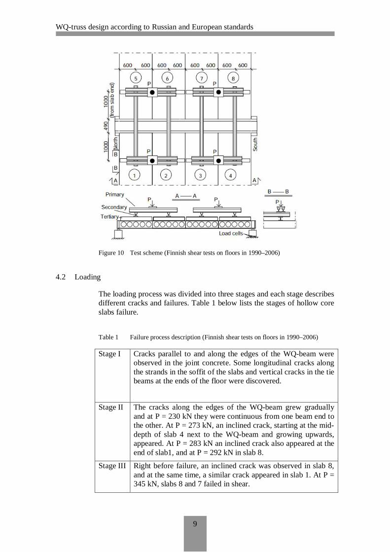
In the pictures below (Figure 9 and 10) the reader can see the test plansand loading conditions. The slabs were supported by the end beam whichis made of hollow section profiles 200*200*12.5, the other part was at-tached to a WQ-profile in the same way as it is supposed to be in a realbuilding. This information will help to imagine the situation.
The WQ-beam had simple (pinned) supports at the ends. The purpose wasto make the load on hollow core slabs close enough to uniformly distribut-ed nature. For that purpose two point loads were separated into several us-ing primary, secondary as can be seen in Figures below.
Test arrangement goal was to simulate the conditions similar to the loadduring an average building exploitation.
The steel grade approximately S350 was used for hollow sections and theWQ-beam.
Figure 9 WQ-beam cross section and HCS geometry (Finnish shear tests on floors in1990–2006)
WQ-truss design according to Russian and European standards
9
Figure 10 Test scheme (Finnish shear tests on floors in 1990–2006)
4.2 Loading
The loading process was divided into three stages and each stage describesdifferent cracks and failures. Table 1 below lists the stages of hollow coreslabs failure.
Table 1 Failure process description (Finnish shear tests on floors in 1990–2006)
Stage I Cracks parallel to and along the edges of the WQ-beam wereobserved in the joint concrete. Some longitudinal cracks alongthe strands in the soffit of the slabs and vertical cracks in the tiebeams at the ends of the floor were discovered.
Stage II The cracks along the edges of the WQ-beam grew graduallyand at P = 230 kN they were continuous from one beam end tothe other. At P = 273 kN, an inclined crack, starting at the mid-depth of slab 4 next to the WQ-beam and growing upwards,appeared. At P = 283 kN an inclined crack also appeared at theend of slab1, and at P = 292 kN in slab 8.
Stage III Right before failure, an inclined crack was observed in slab 8,and at the same time, a similar crack appeared in slab 1. At P =345 kN, slabs 8 and 7 failed in shear.

WQ-truss design according to Russian and European standards
10
In the Figure 11 the reader can see the shear failure of the hollow core slabwhich locates near the WQ-beam. Also, Figure 12 illustrates the schemeof cracks.
Figure 11 Shear failure of a slab (photo) (Finnish shear tests on floors in 1990–2006)
Figure 12 Failure scheme (Finnish shear tests on floors in 1990–2006)

WQ-truss design according to Russian and European standards
11
Appropriate calculations of the shear resistance of one hollow core slabwere performed. The analysis was based on the test results. The capacitywas 166 kN.After the test completed designers decided to organize a test with similarWQ-edge beams and it was amazing when the shear capacity of hollowcore element was 230.5kN.
These results lead to conclusions that WQ-profile influences on the shearcapacity of hollow core slabs.
4.3 Test results
Hollow core slabs utilize only 72% of their capacity when they were usedwith a WQ-beam, comparing to a usual concrete support. The beam didnot yield in the floor test, the capacity loss happened because of the shearfailure of hollow-core slabs.
So, one may see that this test was quite important. The reason is that a hol-low core slab is a complicated post-tensioned concrete element. Its thick-ness is often chosen from experience, or taken from the manufacturer. Asit was many times stated earlier, a WQ-beam system has not yet becomepopular enough. Therefore, it is hard to find a person experienced in itsdesign process. Most of the engineers may not be aware of the slab capaci-ty that becomes around 25% less.
In conclusion, it must be again underlined that this chapter is one of themost important. The phenomenon tested is extremely unobvious, especial-ly for a WQ-truss system that is positioned as a simple, fast and cheap al-ternative to huge cast-in-situ concrete beams. So, a designer must have anadditional discussion with a manufacturer to consider the decreased capac-ity.

WQ-truss design according to Russian and European standards
12
5 JOINTS
Generally, joint design instructions will not be provided in this thesis, butit is necessary to provide typical joints between the WQ-truss and other el-ements which are made of steel or concrete. This information will help tounderstand this system and will make it easier to make detailed drawings.
5.1 Concrete columns
The Figure 13 below shows the typical connection between the WQ-beamprofile and concrete column element. Usually an embedded steel part islocated inside the column and after assembling it is welded with WQ-beam plate. Additionally, stiffeners should be provided for a WQ-beamprofile to ensure stability and safety.
During the installation temporary supports have to be provided. Usuallyhollow core slabs are maintained firstly at one side and only then at theother. As a result there is torsion in the WQ-beam which should be takeninto account during the design process.
Figure 13 Connection between WQ-truss and concrete column(http://www.elementtisuunnittelu.fi/fi/Haku?term=WQ, DTK201:WQ-palkinliitos betonipilariin PCs-konsoli)
5.2 Steel columns
Steel columns have the lock principle. A plate which is welded with a can-tilever tube is located inside the beam. Then the WQ-profile rests on it andtransfers the loads.

WQ-truss design according to Russian and European standards
13
A stiffening plate in the WQ-beam should be provided.
Figure 14 Connection between WQ-truss and steel column
In this case torsion should be avoided using temporary supports.
5.3 Joint between hollow core slabs and WQ-beam
After the installation process longitudinal reinforcement between pre-stressed hollow core slabs and WQ-beam must be provided. Then the con-nection should be casted with concrete filling.
Figure 15 Connection between WQ-truss and hollow core slabs(http://www.elementtisuunnittelu.fi/fi/Haku?term=WQ, DO331: Ontelolaatanliitos WQ-palkkiin (keskipalkki))
The reinforcement bars which are marked in Figure 15 are used to serve asjoint reinforcement and as emergency reinforcement.

WQ-truss design according to Russian and European standards
14
5.4 Connection between WQ-beam and secondary beams
The last detail represents a common solution of a steel beam connection,where steel plates should be welded to the main WQ-beam and to the sec-ondary one. After that the connection is fixed with bolts.
The Figure 16 shows a detail of the connection between the secondarybeam and the main beam.
Figure 16 Connection between WQ-beam and secondary beams(http://www.ruukki.com/Construction/Steel-frame-structures/WQ-beam-system)

WQ-truss design according to Russian and European standards
15
6 EUROCODES AND SNIP
6.1 Russian norms and general information about SNiP
SNiP is a set of rules and normative acts regarding technical, economicaland legal issues which are approved by executive authorities. These rulesgovern the implementation of urban development activities as well as en-gineering and architectural design.
The current normative basis in construction in the Russian Federation fullymeets the reliability and safety of operated and planned construction pro-jects. There have not ever been any accidents because of compliance withexisting standards, but only as an outcome of its violation.
6.1.1 History
Until 1955 there were no comprehensive regulations in construction fieldin Soviet Union. Development of SNiP in Soviet Union started in 1939 byL.A. Serk.Norms were divided by 4 parts:- General information- Design standards- Rules of production and acceptance of works- Estimation norms and rules
Generally, accepted norms contained not only design regulations, but it in-cluded also norms, which determine main responsibilities and rights of anengineer and of an architect.
In the modern world new technologies, calculation methods and softwareare developed every day and nowadays in addition to SNiP, SP are used.SP (Set of Rules) is an actualized version of SNiP, which contains updatedrules and standards.
In addition, manufacturing, qualit and other standarts are also used. Thesenorms are equivalent to European ISO.
6.1.2 Classification and chapters
SNiP is divided into sections; each document has its own number. SNiP aswell as Eurocode is divided into parts depending on the load-bearing ma-terial type, purpose of the structure and structure types.
In this thesis SNiP II-23-81 Steel structures and SNiP 2.01.07-85 Loadsand actions on structures will be taken into consideration together with SP16.13330.2011 and SP 20.133330.2011 correspondingly.

WQ-truss design according to Russian and European standards
16
6.2 SNiP and Eurocodes
A significant package of SNIP for design purposes of various kinds ofstructures is a direct analogue of the Eurocodes, as it is evident from Table2 below. Note that calculation methods of construction designs for limitstates were adopted in the Russian standards before they were included inthe Eurocodes.
Table 2 Comparison of European and Russian norms (Information about harmoniza-tion of normative documents of the Russian Federation with foreign stand-ards, including the European)
Eurocode number European code Russian code
EN 1990 Basis of structuraldesign
GOST 27751- 87
EN 1991 Actions on strcutures SNiP 2.01.07-85*
EN 1992 Design of concretestructures
SNiP 52-01-2003,
EN 1993 Design of steel struc-tures
SNiP II-23-81*
EN 1994 Design of compositesteel and concretestructures
SP 52-101-2003
EN 1995 Design of timberstructures
SNiP II-25-80
EN 1996 Design of masonrystructures
SNiP II-22-81*
EN 1997 Geotechnical design SNiP 2.02.01-83*,
SNiP 2.02.03-85
EN 1998 Design of structuresfor earthquake re-sistance
SNiP II-7-81*
EN 1999 Design of aluminiumstructures
SNiP 2.03.06-85
*Use with corresponding SP
6.3 Calculations according to SP, SNiP and Eurocodes
Both the Russian and European norms estimate the reliability and safety ofa structure using the ultimate limit state and serviceability limit state.However, in SNiP these states are named first and second limit states re-spectively. The calculations must include such factors as classification ofstructures in terms of responsibility, serviceability and durability of astructure.

WQ-truss design according to Russian and European standards
17
The ultimate limit state or the so called first limit state determines thesafety of a structure. The serviceability limit state or second limit stateconcerns the comfort of use and appearance of a structure.
During the actualization of SP, calculation methods and approaches wereadapted to international standards. In the Russian norms there is a unifiedmethod for the estimation of design loads taking into account safety fac-tors as it is done in Eurocodes.

WQ-truss design according to Russian and European standards
18
7 DESIGN OF WQ-TRUSS ACCORDING TO RUSSIANSTANDARDS
7.1 Structural analysis
For WQ-truss design there is no clear definition of what kind of structuralanalysis should be used in Russia. In the case of an average truss it is not adisadvantage, because a designer does not face bending moments (statical-ly determinate structure) and there are no possibilities to apply materialnon-linearity in a global analysis. However, for a WQ-truss it could bebeneficial to use plastic analysis for the upper chord in bending, because itreduces bending moments in critical points as in the Figure 17 below. Asfar as in the standard there are no clear regulations, this thesis is limited toa global elastic analysis with no bending moment redistribution.
Figure 17 The influence of plasticity in structural analysis. a) – calculation model, b) –elastic bending moments, c) – plastic bending moments (R.S. Narayanan, A.Beeby,Designers’ guide to EN1992-1-1 and EN1992-1-2, 2009)
7.2 Initial imperfections and second order effects
According to the Russian norms no global second order effects are consid-ered. Instead of that the same method as in Eurocode 3 is used for alocalmember verification. P-delta effects and relevant geometry inclinations arebuilt in the formulas for the buckling resistance of members.
7.3 Modeling
Usually a truss is subjected to external loads at its node points. That resultsto only axial forces in bracing members. However, this is not the case with

WQ-truss design according to Russian and European standards
19
the WQ system that is intended to support uniformly distributed floorstructures. This is why secondary moments in bracing elements must beconsidered when the design is done according to the Russian standards.
Figure 18 Secondary moments in bracing elements
In the Russian standards there are no clear rules about this design aspectand it is wise to take these moments into account. However in Eurocode1993-1-8 in clause 5.1.5 there are special requirements, which allow ig-noring secondary moments altogether.
7.4 Fundamental components of member resistance
In general, it can be pointed out from both standards that resistances de-pend on several determinant aspects which should be highlighted in thisthesis.
The first one is geometrical properties of the member cross section. Simp-ly, the bigger it is the more force it can take. Anyway, for different failuremodes the cross section must be larger in different parts. For instance, agood bending resistance is achieved by a high value of second moment ofinertia. This means that a member section should be very deep. On thecontrary, the resistance in axial compression increases with the cross sec-tion enlargement independently of the location of the enlarged parts.
Secondly, material properties are also sufficient. Steel with a better yieldstrength is allowed to be subjected to higher stress values.

WQ-truss design according to Russian and European standards
20
8 LOAD DETERMINATION
8.1 Load classification
Different loads are considered with their own factor in the European andRussian norms: permanent, variable and accidental load types can be dis-tinguished. For a better understanding of load types see Table 3.
Table 3 Comparison of main load cases in European and Russian load classification
Load type,symbol
SP20.13330.2011
Permanent, Pd · self-weight of structures· hydrostatic pressure· soil pressure· prestressing
Long-term ac-tions, Pl
· temporary structures· construction equipment weight· stored materials in warehouses,
fridges and these kinds of rooms· shrinkage of a structure
Short-term ac-tions, Pt
· snow and wind loads· live load· self-weight of transport equipment· self-weight of people and equip-
ment and materials during repairworks
Accidental, Ps · explosions· seismic actions· loads from fire accidents· loads from transport accidents· loads because of malfunction of
some equipment· loads caused by deformations like
from soaking of soil
This scheme differs a little bit from the Eurocodes, but the calculationprinciple is the same. The general design load formula is provided below:
[SP 20.13330.2011]
The ultimate limit state principle implies that maximum design affectingforce is less than the design element resistance as it is done in the Europe-an standard. Safety factors and load combinations will be described below.

WQ-truss design according to Russian and European standards
21
8.2 Load combinations
As for the Russian Federation the following load combinations are given:
- The main combination type which includes permanent, long-term andshort-term actions:
[SP 20.13330.2011, Chapter 6.2 a, 6.1]
- Accidental combination type, which includes accidental actions:
[SP 20.13330.2011, Chapter 6.2 b, 6.2]
Coefficient for long-term actions:
Coefficient for short-term actions:

WQ-truss design according to Russian and European standards
22
9 SAFETY FACTORS
9.1 Material safety factor
The design yield strength of material depends on a stress condition. Themain cases are described below [SP 16.13330.2011, Chapter 6.1, Table 2]:
- Bending, tension and compression
= /
= /
- Shear
= 0.58 /
Actually, the material strength does not anyhow change when it comes toshear. The coefficient 0.58 comes from the Von Misses yield criteria,where to obtain shear stress τ axial stress σ is divided by square root of 3(or multiplied by about 0.58). Since in SNIP the designed value of shearstress is compared with resistance, the latter must represent the maximumτ that material can take.
In the Russian standard material properties are taken into account by usingthe following coefficients of material reliability according toSP16.13330.2011, Chapter 6.2, safety factors are defined by a nomencla-ture of steel profiles, called GOST. GOST is a state standard which in-cludes a list of possible cross section types with specifications and ownrequirements.
Material safety factors are divided into four possible variants[SP16.13330.2011, Chapter 6.1, Table 3]:
- GOST 27772 (except steel S590 and S590K) and other normativedocumentation which uses the same control procedure, γm=1.025
- GOST 19281 and GOST 8731 for steel with yield strength which ismore than 380 N/mm2, γm=1.100
- Other profiles which satisfy the normative requirements, γm=1.050- For profiles which are supplied using foreign normative documenta-
tion, γm=1.100
9.2 Consequence and reliability factors
The liability of the building and facilities when designing using limitstates is determined by the size of the material and social damage. Thesafety factor value depends on the class of responsibility for buildings orstructures. In order to take into account consequence classes of structures,buildings were divided into three groups [SNiP 2.01.07]:

WQ-truss design according to Russian and European standards
23
- I - high risk- II - normal risk- III - low risk
The first group corresponds to buildings which typically include oil facto-ries, unique buildings and structures with the height and span more than100m. A collapse of such constructions can lead to significant economic,social and ecological losses, 0.95≤ γn≤1.2.
Next, the second group should be applied to residential, commercial andpublic buildings γn = 0.95.
Last one, the third group is used for seasonal and auxiliary constructionssuch as greenhouses, small warehouses and similar facilities, 0.8≤ γn≤0.95.
The following safety factor should be used to reduce the bearing capacityand resistances of buildings and maximum deformations should be dividedby this factor. Besides that it is necessary to multiply design loads and allother acting forces on γn.
9.3 Coefficient for working conditions
The coefficient for working conditions is used in purpose to decrease theresistances depending on element and stress type. Due to the large numberof various situations in this article the information will be limited to themain beam cases.
Beams and compressed elements of trusses in public and commercialbuildings γc = 0.9. [SP 16.13330.2011, Chapter 4.3.2, Table 1]
9.4 Safety factor for ultimate resistances
If a designer makes calculations using the ultimate yield strength of steel,then it should be applied with factor γu = 1.3. [SP 16.13330.2011, Chapter4.3.2]
9.5 Coefficient depending on loading type
The next factor which is taken into account considers loading type.
Steel structures γf=1.05Concrete structures γf = 1.1Dead load γf = 1.05Wind load γf = 1.4Snow load γf = 1.4

WQ-truss design according to Russian and European standards
24
10 SNOW LOADS
In northern countries precipitations have significant effect on building de-sign while calculating loads caused by snow. There are several factors af-fecting a snow load analysis which includes accumulated snow in differentregions and roof shape. Usually, the snow load is formed during the wholewinter season. When the snow load is moved by wind, it can also be melt-ed because of the building heat and from the warm temperatures.All those aspects are taken into account in the Russian standard using theshape factor µ and navigating by zoning maps.
10.1 Shape coefficient
In order to cover the usual cases of the buildings it is more understandableto systematize the information creating a table according to SP20.13330.2011. Table 4 contains all usual types of roofs and correspond-ing coefficients µ.
Table 4 Coefficients µ
Roof and load scheme Coefficient µ
Monopitched and duopitched roofs µ=1 if α≤25ᴼ
µ=0 if α≥60ᴼ
Variants 2 and 3 shouldbe used for duopichedroofs, besides that vari-ant 2 if 20 ≥α≤30 andvariant 3 if 10 ≥α≤30,but the last one shouldbe used only if there arethe walking bridges oraeration devices on theridge cover

WQ-truss design according to Russian and European standards
25
Two- and multi-span building with gable covers Variant 1 should be ap-plied if α≤15ᴼ
Buildings with parapets If h>S0/2, then µ=2h/ S0,but not more than 3.
For special cases theincreased load becauseof snow drift should betaken into consideration.
10.1.1 Characteristic snow load
The formula below provides general formula of snow load given in Rus-sian SP. This equation contains the same factors as Eurocodes.
= 0.7 [SP 20.13330.2011, Chapter 10.1, 10.1]
where,cв – coefficient of wind effect, Chapter 10.5ct – thermal effect, Chapter 10.6µ- shape factorSg – snow load on ground
The influence of the terrain type is expressed using the coefficient cв in-cluding the it includes wind velocity effect. This factor makes the designprocess easier to avoid huge snow drifts.
The map below in Figure 19 shows the average wind velocity dependingon the region of Russia, the value is given in m/s. All maps can be foundin Appendix Ж of SP.

WQ-truss design according to Russian and European standards
26
Figure 19 Average wind velocity in winter period in Russian Federation [SP20.13330.2011, Appendix Ж]
If the wind in winter time is less than 2m/s and the roof slope is less than12% then the formula below has to be applied:
= 1.2 − 0.1 √ (0.8 + 0.002 ) [SP 20.13330.2011, Chapter 10.5,10.2]
where,k – coefficient depending on terrain type, can be found in Table 11.2 of SPb – width of the coverings, not more than 100mV – average wind velocity, this value can be found from the map of aver-age wind velocity in winter period, see Figure 19
Terrain type coefficient depends on height zв [SP 20.13330.2011, Chapter11.1.5], which is:
Then a designer has to consider the terrain type category of the building[SP 20.13330.2011, Chapter 11.1.6]:
- A – countryside, tundra, seaside or places near the lakes, reservoirs,where buildings height is less than 10m
- B – cities, forests and other places with obstacles which are higherthan 10m
- C – cities with dense buildings higher than 25m

WQ-truss design according to Russian and European standards
27
The last step is to see the Table 11.2 of SP which is shown below as a Ta-ble 5.
Table 5 Coefficient k [SP 20.13330.2011, Chapter 11.1.6, Table 11.2]
For single-span and multi-span buildings with the roof slope from 12 to20% which are located in the regions with the velocity value is more than4, cв=0.85. [SP 20.13330.2011, Chapter 10.3, 10.6]
In case of skyscrapers higher than 75m with a slope less than 20% it is al-lowed to take cв as 0.7. For more information and other cases see SP20.13330.2011, Chapter 10.
The thermal coefficient is used in purpose to reduce the snow load onroofs with a high thermal transmittance value, where ct=0.8 In all othercases take ct as 1.
Snow load on the ground is provided in the zoning map the of RussianFederation by the snow load on the ground, see Figure 20 below.

WQ-truss design according to Russian and European standards
28
Figure 20 Zoning by snow load on the ground in Russia[SP 20.13330.2011, AppendixЖ]
After the determination of the correct region a designer finds the snowload of SP which can be seen below in Table 6.
Table 6 Characteristic snow load [SP 20.13330.2011, Chapter 10.2, Table 10.1]

WQ-truss design according to Russian and European standards
29
11 WIND LOAD
In a side-wind pressure air flow collides with the wall and the roof of thebuilding. Near the wall of the house the wind goes swirling, besides thatsome of it goes down to the foundation, and the other at a tangent to thewall hits the eaves of the roof and uplifts roof corners. As the wind pres-sure causes suction pressures, claddings and roof structure should be se-curely fixed. The flatter the roof, the higher the suction forces are actingon it. Figure 21 below illustrates the typical behavior of a structure whenwind acts on it.
In addition, corners of the roof are lifted up by the wind.
Figure 21 Wind suction(https://www.dlsweb.rmit.edu.au/toolbox/buildright/content/bcgbc4010a/01_loads_loading/01_primary_loads/page_006.htm)
Wind pressure depends on several factors such as the shape of the roof,orientation of a building and wind velocity.
As it is stated in SP 20.13330.2011, Chapter 11 the characteristic windload is determined by adding a fluctuating component of wind load to theaverage wind load.
= + [SP 20.13330.2011, Chapter 11.1.2, 11.1]
wherewm – average wind loadwp – fluctuating wind load
The first one can be calculated using the following formula below:
= ( ) [SP 20.13330.2011, Chapter 11.1.3, 11.2]
In the expression above w0 is the characteristic wind load depending onthe wind pressure regions. This information is given in the wind pressuremap of the Russian Federation.(Figure 22)

WQ-truss design according to Russian and European standards
30
Figure 22 Wind pressure map of Russian Federation [SP 20.13330.2011, Appendix Ж]
After that, factor k contains information about the change of wind pressuredepending on terrain type. This coefficient was discussed above.
Then, aerodynamic coefficient c, which takes into account the direction ofthe wind in relation to the structure, should be found. Table 7 below showsclear information about the way of detecting the aerodynamic coefficientaccording to SP.

WQ-truss design according to Russian and European standards
31
Table 7 Aerodynamic coefficient c [SP 20.13330.2011, Chapter 11.1.7]
The last step is to find the pulsation wind pressure using the formula:
wp = wmζ(ze)υ, [SP 20.13330.2011, Chapter 11.1.8, 11.5]
where
ζ(ze) – coefficient of wind pulsation related to terrain type
In the Table 8 the reader can find the wind pulsation coefficient accordingto the Russian standard.

WQ-truss design according to Russian and European standards
32
Table 8 Wind pulsation coefficient [SP 20.13330.2011, Chapter 11.1.8, Table 11.4]
υ - coefficient of a spatial pulsation, this factor depends on coefficients ρand χ
The Table 9 and 10 below will help to determine the orientation factors ρand χ.
Table 9 Orientation factors ρ and χ [SP 20.13330.2011, Chapter 11.1.11, 11.6]
Table 10 Spatial pulsation coefficient [SP 20.13330.2011, Chapter 11.1.11, 11.7]

WQ-truss design according to Russian and European standards
33
12 DESIGN CONSIDERATIONS, FIRST LIMIT STATE
12.1 Web stability check
In SNiP there are several requirements for local stability of a flange and aweb, where is generally accepted that separate elements of a profile workas plates which attached either rigid or pinned (sometimes even as aspring) to each other. Local buckling can happen in compressed flange orin the web under the influence of bending and axial forces.
Mainly, upper flanges of WQ-beam in WQ-truss system bear compressionfrom axial forces and compression caused by bending moment, howeverlower flange takes tension from bending moment, axial compression andalso load which comes from hollow core slabs or shell slabs. If stresseswill exceed critical values, flanges will lose local stability and consequent-ly the beam will lose the load-bearing capacity.
In Russian standard critical stresses depend on yield of steel and on di-mensions of a plate and stresses shouldn’t be more than design yieldstrength, otherwise elements of a profile will lose stability before the beamin general. Elastic analysis is used in design process to be on the safe side.
12.1.1 Web local resistance
Web nominal slenderness should be calculated using the formula:
= / [SP 16.13330.2011, Chapter 7.3.2]
wherehef - the full height of the web in welded profiles or distance between in-ternal roundings in rolled sections,tw - thickness of the web,Ry – design yield strength of steel
For further information about effective height see the Figure 23 below.

WQ-truss design according to Russian and European standards
34
Figure 23 Design cross section parts dimensions[SP 16.13330.2011, Chapter 7.3.1, Fig-ure 5]
The web of the WQ-beam is welded from one side. Consequently it is sta-ble if nominal slenderness doesn’t exceed the value 3.2 [SP16.13330.2011, Chapter 8.5.9]. In case of excessive nominal slenderness adesigner should add stiffeners. Other beams in the truss should be checkedin the same way.
12.2 Normal forces
Based on the technical guide in strength of materials, axial force repre-sents a special type of deformation when in cross section there are onlytension or compression stresses, while bending and shear forces equal tozero. (Darkov and Shapiro, Strength of materials, 1989)
In Chapter 7.1.1 of SP the following condition should be satisfied:
≤ 1
[SP 16.13330.2011, Chapter 7.1.1, 5]
N – design normal forceAn – cross section areaRy – design yield strength of steel
The main idea is similar to the idea of Eurocodes, where design normalforce should be less than design tension or compression resistance.

WQ-truss design according to Russian and European standards
35
12.3 Bending moment resistance
The equation below and design condition in the Eurocode have the samemeaning, where the design moment in a nominator has to be less than thedesign bending resistance in the denominator. The moment resistance isreduced by material safety factor and by working condition factor as it isstated in Chapter 8.2.1 of SP.
,≤ 1
[SP 16.13330.2011, Chapter 8.2.1, 41]
12.4 Shear design
Concerning shear force impact the most vital part of the truss will be theupper chord. The critical points are located near the truss supports. In ac-cordance with Chapter 8.2.1 of SP:
≤ 1
[SP 16.13330.2011, Chapter 8.2.1, Table 42]
12.5 Complex stress of bottom flange
In the Russian standard the combined bending and shear section resistanceis verified by the following formula:
0.87 − + + 3 ≤ 1, / ≤ 1
[SP 16.13330.2011, Chapter 8.2.1, Table 44]
An experienced person recognizes Von Misses yield criteria in the twodimensional situations, that is reduced by the safety factor 0.87.
12.6 Combined bending, shear and axial force
For verification of the resistance during the simultaneous actions of bend-ing, normal and shear forces it is required to add stresses caused by axialforces to the formula above, which will guarantee the stability of a crosssection.
12.7 Torsion
This problem is not highlighted in this thesis. The reason is that centerWQ-beam profile is not subjected to torsion, because it is laterally re-straint.

WQ-truss design according to Russian and European standards
36
Torsion during the loading and installation period is avoided by temporarysupports.
12.8 Member stability check of WQ-truss
12.8.1 Flange local resistance
Flange local resistance is determined in the same way. The nominal slen-derness can be calculated applying the following formula:
= / [SP 16.13330.2011, Chapter 8.4.4, b]
Where bef – width of the flange, see Figure 24
The stability of the flange is ensured if the characteristic nominal slender-ness is less than the ultimate slenderness value which can be calculatedfrom Table 11 below:
Table 11 Ultimate nominal slenderness [SP 16.13330.2011, Chapter 8.4.4, Table 11]
Condition Formula
Upper flange 0.35+0.0032b/t+(0.76-0.02b/t)b/h
Lower flange 0.57+0.0032b/t+(0.92-0.02b/t)b/h
Between bracing elements ofthe beam or when only bend-ing stresses exist
0.41+0.0032b/t+(0.73-0.016b/t)b/h
Note! Ultimate nominal slenderness values are determined for beams with1≤ h/b ≤6 and 15≤ b/t ≤35, if b/t<15 then this value should be taken asb/t=15.
12.9 Lateral-torsional buckling
In SP it is stated that if a beam is laterally restrained it is not required tocheck this aspect. Thus, WQ-beam in the WQ-truss system is laterallyfixed by hollow core slabs, so a designer can consider it laterally stable.

WQ-truss design according to Russian and European standards
37
13 DEFLECTION LIMITS, SECOND LIMIT STATE
Large deformations can lead to leakages, poor aesthetic perception of abuilding and can influence on the comfort of people who use this building.Thus, deformation limitation is an essential point in the design process.
Based on SP 20.13330.2011 Annex E2 the WQ-truss system belongs tothe structure type 2 – beams, trusses, floor structures, where the span isabout 20m the deflection limit is l/250, see Table 12 to get acquainted es-pecially with truss deflection requirements of SP. Table 12 below lists themost common situation during the WQ-truss design according to SP.
Table 12 Deflection limit for trusses, beams and floor structures [SP 20.13330.2011,part of Table E.1]
Constructionelements
Requirements Deflection limit Actions
2. Beams, trusses,different floorstructures, coversa) Visible partsSpan length l, m:
l = 24(12)l ≥ 36(24)
b) With partitionwalls below thestructure:
aesthetic andpsychological
structural
l/250l/300
Element deflectionshould not exceedthe gap distancebetween a wall andthe lower edge of anelement.The gap between thelower surface of amember and a wallshould not be morethan 40 mm.In case, if this gapincreases the stiff-ness of floor struc-ture, the designershould avoid usinglarger gaps
Permanent andlong-term
Actions whichreduces thegap between awall and lowersurface of afloor structure.

WQ-truss design according to Russian and European standards
38
14 DESIGN ACCORDING TO EUROPEAN STANDARDS
14.1 Global frame analysis methods
The purpose of structural analysis is to obtain internal moments and forc-es.
Firstly, the analysis can be implemented as a global elastic analysis orglobal plastic analysis.
An elastic analysis is carried out based on linear stress-strain relation ofsteel, where in elastic case the stresses caused by applied forces of a struc-ture are less than the yield strength of steel. (Luis Simoes da Silve, RuiSimoes, Helena Gervasio,Design of steel structures, 2010)This method can be used in all cases, but design resistances of memberscan be estimated using a plastic capacity
Then, a plastic analysis allows material non-linear behavior (yielding),which leads to force redistribution from yielded parts to those that remainelastic. It is essential that a member should be able to develop a large de-formation without a local buckling.
Secondly, analysis methods can be divided into 1st order or 2nd order. Thefirst order analysis doesn’t take into account the effect of deformationwhich occurred because of acting forces. In addition, applied forces areproportional to the deformations, so that a designer can apply the principleof superposition of effects to simplify calculations.
Figure 24 shows the first order analysis scheme.
Figure 24 First order analysis
In contrast, the second order analysis considers all factors. High com-pressed structures and structures with low stiffness are more subjected tosecond order effects. The calculations are performed using iterative meth-ods with suitable software.
Figure 25 illustrates the scheme of the second order analysis with P-δ ef-fects.

WQ-truss design according to Russian and European standards
39
Figure 25 Second order analysis, P-δ effects (local effects), P-Δ effects (global effects)
To summarize everything above, practical differences in displacementsone can see in Figure 26 below. In plastic cases material behavior is as-sumed to be without hardening.
Figure 26 Types of analysis (European Erasmus Mundus Master Course, ConceptualDesign of Buildings)
Being a floor or a roof structure, the WQ-truss is responsible for transmit-ting lateral loads to bracing elements of buildings (walls, diagonal brac-ings, etc.). Therefore, its internal forces depend quite a lot on horizontaleffects acting on columns, though the WQ-truss itself is considered tohave only local imperfections. This is why any of the analysis types abovewill give different results.
Besides, having a large number of points with different hogging and sag-ging moments in the upper chord opens great possibilities for the plasticanalysis contrary to a usual truss where chords in most cases do not haveany internal moments.
14.2 Elastic versus plastic analysis types
In the European standard there are two types of analysis in terms of stress-es, deformations and forces: plastic and elastic.The elastic analysis is based on a linear behavior of a member, so that inorder to ensure the safety of a structure stresses should be less than yieldstrength (fy) of steel.

WQ-truss design according to Russian and European standards
40
The second type allows the plastic behavior of steel and redistribution ofinternal forces to other elements. After the material reaches its yield limita plastic hinge is formed. Consequently a designer should use compactsections and ductile materials. The bending moment which can producethese stress diagrams is called plastic bending moment. The Figure 27 be-low shows the cross section behavior, where the last diagram reflects fullyplasticized section.[8]
Figure 27 Cross section behavior. a) strain diagram in all cases b) stress diagram inelastic state c) elasto-plastic state d) plastic state (European Erasmus MundusMaster Course, Conceptual Design of Buildings)
14.3 Modeling
As it is stated in the standard, the distribution of axial forces in braced el-ements may be determined on the assumption that the members are con-nected by pinned joints.
Secondary moments at the joints, caused by the rotational stiffness of thejoints, may be neglected both in the design of the bracing members and inthe design of the joints, provided that the conditions specified in Eurocode1993-1-8, clause 5.1.5 are satisfied.
Typical joints between the WQ-profile and hollow sections are called K-joint and Y-joint in the European standard. These names will help a de-signer to use the Table 7.8 of Eurocode, corresponding to that is one of thecriteria needed for a pinned joint assumption as described in 5.1.5. Figure28 shows the case of WQ-truss connections and gives explanations of ge-ometrical data according to the Eurocode 1993-1-8.
Figure 28 Types of joints [EN 1993-1-8, 7.1.2]

WQ-truss design according to Russian and European standards
41
Figure 29 Explanation of geometrical data[EN 1993-1-8, Figure 1.4]

WQ-truss design according to Russian and European standards
42
15 LOAD DETERMINATION
Different loads are considered with its own factor in the European norms:permanent, variable and accidental load types can be distinguished. For abetter understanding of the load types see Table 13.
Table 13 Load classification
Load type,symbol
Eurocode 1990
Permanent, G · self-weight of structures· fixed equipment· indirect actions· road surfacing· presteressing
Variable, Q · imposed loads on building floors· beams and roofs· wind actions or snow loads· *certain actions, such as seismic actions and
snow loads, may be considered as eitheraccidental and/or variable actions, dependingon the site location, see EN 1991 and EN1998.
Accidental, A · explosions· impact from vehicles
15.1 Load combinations
Typically, a European analysis of load combinations is implemented withunfavorable load combinations, where action values are reduced by usingseveral factors.
15.1.1 Eurocodes
National Annex of Finland gives the following formulas for load combina-tions, where a designer should choose the infavorable one:
[National Annex of Finland to Standard SFS-EN 1990, Table A1.2(B)(FI)]
KFI gives extra safety taking into consideration consequence classes ofbuildings where the main factor is a loss of human life and economic, so-

WQ-truss design according to Russian and European standards
43
cial and environmental consequences. Reliability classes are directly relat-ed to consequence classes.
Reliability class 3 means high consequence, class 2 means medium conse-quence and class 1 is low consequence.
- For reliability class 3 RC3, KFI=1,1- For reliability class 2 RC3, KFI=1- For reliability class 1 RC3, KFI=0,9
[National Annex of Finland to Standard SFS-EN 1990, TableA1.2(B)(FI)]
Ψ-factors are given in Table A1.1 in National Annex of Finland, Eurocode1990.

WQ-truss design according to Russian and European standards
44
16 SAFETY FACTORS
Generally, basic instructions concerning partial safety factors are given inEurocode 1990, Basis of design. The main idea is that design load shouldbe less than design resistance values.
The design load is determined by increasing the characteristic load bysafety factor γn. This topic is highlighted above. Besides that characteristicresistance values should be decreased by safety factors which take into ac-count geometrical and material properties of a profile, that factor is calledγM.The factor γM = 1,00 is used mainly for cross section resistance check.Next factor γM1 = 1,00 is applied in member stability check.Last one, γM2 =1,25, is used for design of resistance of cross-section intension to fracture. [11]

WQ-truss design according to Russian and European standards
45
17 SNOW LOAD DETERMINATION PROCESS
In order to find out the characteristic snow load value a designer should dothe same procedure as in the Russian norms, where the roof shape, thermaltransmittance and region influence the final result.
= μ C C s [EN 1991-1-3, Chapter 5.2, 5.1]
Where:μi – snow load shape coefficientCe – wind shield factor, usually Ce = 1, depends on topographyCt – temperature factor, Ct = 1sk – snow load on ground
The snow load shape factor μi depends on the roof type and slope, the co-efficients takes into account the influence of wind, which can move snowand cause snow drifts.
These values μ1 and μ2 are applied when the snow is not prevented fromsliding off the roof (no snow fences or other obstructions like parapets). Ifobstructions exist, the snow load shape coefficient should not be reducedbelow 0.8. Table 14 below represents the most common and simple caseswhich are shown here to point out that it looks similar to the Russiannorms. More complicated situations are described in Eurocode 1991-1-3.
Table 14 Snow load shape coeficient [EN 1991-1-3, Chapter 5.3]
Roof and load scheme Coefficient µ
Mono-pitched and pitched roofs From the diagram below it iseasy to find shape coefficient.
Multi-span roofs

WQ-truss design according to Russian and European standards
46
After the shape factor is determined, it is required to choose the correctcharacteristic load. In fact, it is influenced by National Annexes, for ex-ample in Finland a zoning National map was created. It is obvious that de-pending on the location different snow load values can be found, see Fig-ure 30 below.
Figure 30 Snow load on ground in Finland [NA EN 1993-1-3]
In purpose to summarize all the information above, see the flowchart,where snow load determination methods are described very clear.(Figure31)

WQ-truss design according to Russian and European standards
47
Figure 31 Snow load determination process according to Eurocodes(http://sections.arcelormittal.com/fileadmin/redaction/4-Library/4-SBE/EN/SSB03_Actions.pdf)

WQ-truss design according to Russian and European standards
48
18 WIND LOAD
18.1 Wind force
The general formula of wind force acting on a structure or on an elementis shown below:
= c c c q (z )A [EN 1991-1-4, Chapter 5.3, 5.3]
The first step is to the find peak velocity pressure, which is represented asqp(ze). It depends on the terrain type, reference height and basic wind ve-locity, which can be found in the National Annex. The whole procedure offinding the peak velocity pressure is time-consuming. In Finland it is pos-sible to use the simplified diagram from RIL 201-1-2011, chapter 4.5.5.The Figure 32 represents the diagram from RIL.
Figure 32 Peak velocity pressure (RIL 201-1-2011)
Factor cscd may be taken as 1 if the height of the building is less than 15m,for more difficult cases see Eurocode 1991-1-4 Chapter 6.3.1.
Coefficient cf takes much time to be calculated according to Eurocodes.Thus, it is less complicated to use a simplified method according to RIL201-1-2011, chapter 5.2.5. This coefficient can be seen on the Figure 33.

WQ-truss design according to Russian and European standards
49
Figure 33 Force coefficient diagram (RIL 201-1-2011)
This graphic is applied when slenderness is less than 10m.- When h<15 m, λ =2h/b- When h50 m, λ =1.4h/b- When 15m < h < 50m values are interpolated
The table from RIL is provided below. Table 15 may also be appliedin purpose to find the force coefficient:
Table 15 Force coefficient table (RIL 201-1-2011)
The reference area Aref is the area of a component perpendicular to the act-ing wind force.
18.2 Wind external and internal pressure
In a practical approach, a designer should usually have information aboutinternal and external pressure values to know how much pressure is ap-plied to load bearing structures, small elements and fixings. A direct pres-sure is taken commonly as positive and suction as negative. These valuescan be found by multiplying the peak velocity pressure on internal or ex-ternal pressure coefficients. The pressure factors can be obtained from thetables, Chapter 7 of the Eurocode 1991-1-4.
= ( ) [EN 1991-1-4, Chapter 5.2.1, 5.1]
= ( ) [EN 1991-1-4, Chapter 5.2.2, 5.2]
It is necessary to point out that factor cpe,1 is applied to small elements andfixings and cpe,10 is used for an overall load bearing structure.

WQ-truss design according to Russian and European standards
50
19 CROSS SECTION CLASSIFICATION
Generally, the method offered in the European standard suggests finding across section class of each profile to check the cross section stability. Onthe other hand, the classification procedure is essential to choose themethod of global analysis: plastic or elastic.
If flanges and webs are considered separately, it is clear that these ele-ments are relatively thin and subjected to local buckling. Thereby, this as-pect influences the load-carrying capacity. (Steel Buildings - British Con-structional Steelwork Association)
The consequences of local buckling are visible in Figure 34.
Figure 34 Examples of local buckling effect(https://www.tue.nl/en/university/departments/built-environment/research/units/structural-design/research/completed-phd/local-buckling-of-slender-aluminium-sections-exposed-to-fire/)
Altogether, there are four types of cross sections which characterize thebehavior of an element.
Table 16 Cross section classes [EN 1993-1-1, clause 5.5]
Cross section class 1 Cross section class 1 represents those pro-files which can form a plastic hinge withthe rotation capacity required from plasticanalysis without reduction of the resistance
Cross section class 2 Cross-sections which belong to cross sec-tion class 2 are those which can developtheir plastic moment resistance, but havelimited rotation capacity because of localbuckling.
Cross section class 3 Cross-sections which can be considered ascross section class 3 are those in which thestress in the extreme compression fibre ofthe steel member assuming an elastic dis-tribution of stresses can reach the yieldstrength, but local buckling is liable to pre-vent development of the plastic moment

WQ-truss design according to Russian and European standards
51
resistance.
Cross section class 4 Cross sections which correspond to crosssection class 4 are those in which localbuckling will occur before the attainment ofyield stress in one or more parts of thecross-section.
For a common profile all elements should be checked: bottom flange, up-per flange and web. These calculations must be implemented according toEurocode 1993-1-1, Chapter 5.6, where appropriate tables with compara-ble values can be found.
In Eurocode 1993-1-1 cross section class classification is done by using atable. It consists of three sheets which include information about internalcompression parts, outstand flanges and angular and tubular sections.
Also, the steel strength factor should be found according to the formula:
=235
[EN 1993-1-1, Chapter 5.6, Table 5.2]
After the calculation part, a designer chooses the least favorable cross sec-tion class.
19.1 WQ-beam cross section check
As it is stated in TRY Steel Standard Card No 21/2009, WQ-beam flangesand web are usually so thick that the profile belongs to cross section class1 or 2. Sometimes the WQ-profile is so asymmetric that a plastic neutralaxis is located near the bottom flange; in this case a designer can deal withcross section categories 3 or 4.[4]
The cross section with web of cross section class 3 and flanged of class 1or class 2 can be classified as cross section class 2 using the method of ef-fective webs. For more clear information about effective parts see the dia-grams below in Figure 35.

WQ-truss design according to Russian and European standards
52
Figure 35 Effective parts of WQ-beam[4]

WQ-truss design according to Russian and European standards
53
20 DESIGN CONSIDERATIONS, ULTIMATE LIMIT STATE
20.1 Cross section resistance
In the European standard the main point and condition is the that designeffect value has to be less than the design resistance value. This logic isapplied in cross section and member stability checks.
20.1.1 Tension and compression
Tension and compression resistances of steel profiles should be more thandesign normal force acting on a profile.
,≤ 1,0
[EN 1993-1-1, Chapter 6.2.3, 6.5]
,≤ 1,0
[EN 1993-1-1, Chapter 6.2.4, 6.9]
Tension resistance formulas will be mostly applied to the design of brac-ings of the WQ-truss system and for the bottom chord.
, =0.9
[EN 1993-1-1, Chapter 6.2.3, 6.7]
, =A
[EN 1993-1-1, Chapter 6.2.3, 6.6]
Compression resistance check has to be provided for the upper chord andbracings.
, =A
[EN 1993-1-1, Chapter 6.2.4, 6.10]
, =A
[EN 1993-1-1, Chapter 6.2.4, 6.11]

WQ-truss design according to Russian and European standards
54
As one may see, the main purpose of these formulae is to prevent materialyielding, which will lead to a failure. In case of tension, plastic behaviormay be allowed, while possible fracture is sometimes more important forsections with holes.
20.1.2 Bending moment
The values of design bending moment resistance and design bending mo-ment should satisfy the following equation:
,≤ 1,0
[EN 1993-1-1, Chapter 6.2.5, 6.12]
Design moment resistances formulas for a selected cross section class areprovided below.First and second cross section classes:
, = M , = W fγ
[EN 1993-1-1, Chapter 6.2.5, 6.13
Third cross section class:
, = M , = W , fγ
[EN 1993-1-1, Chapter 6.2.5, 6.14]
Fourth cross section class:
, = W , f
γ
[EN 1993-1-1, Chapter 6.2.5, 6.15]
Again, the main idea is to avoid excessive yielding. But in this case, localbuckling is also taken into consideration by introducing cross-section clas-ses. The section types 1 and 2 will lose their capacity by reaching the yieldlimit within the whole section. As for the classes 3 and 4, the resistance islimited due to local buckling, in other words, poor rotational capacity. Toavoid the derivation of complicated formulae for the plate buckling phe-nomena, it was agreed to limit the capacity of section type 3 to the initia-tion of plastic deformations. Generally, the tests have shown that no platebuckling phenomenon happen while a class 3 section remains elastic. Un-fortunately, it cannot be achieved for the type 4. Therefore, if a designerwants to use it, he has to apply the Eurocode 1993-1-5 to account buckledparts of a cross-section that are called “ineffective”.

WQ-truss design according to Russian and European standards
55
20.1.3 Shear strength
Shear design is implemented in the same way; each cross section shouldsatisfy the following expression:
,≤ 1,0
[EN 1993-1-1, Chapter 6.2.6, 6.17]
This thesis doesn’t cover torsion. Therefore, according to the Eurocode1993-1-1, the plastic shear resistance can be found from the equation be-low:
. =A (
f√3
)
γ
[EN 1993-1-1, Chapter 6.2.6, 6.18]
Where Av is the shear area; this information can be found in Chapter 6.2.6.
Steel is a very ductile material that has an identical resistance to tensionand compression. As we know from the principal stress theory, pure shearloading is represented by normal stresses inclined by the angle of 45 de-grees as it is shown in Figure 36.
Figure 36 Illustration of principal stresses: left – a section part loaded with shear, nor-mal and transverse stresses; right – “resultant”, principal stresses in that part(http://emweb.unl.edu/NEGAHBAN/Em325/16-Mohr%27s-circle/Mohr%27s%20circle.htm)
In Figure 36 above it is notable that besides the tension principal stresssigma 1, there also exists the same magnitude compression which is nor-mal to the tension (sigma 2).
As stated above, usually this does not matter for steel, because there is nodifference whether the shear failure occurs because of tension, or com-pression (the resistance is equal). However, if an element is slenderenough, compression becomes vital since a local buckling may happen, aso-called “shear buckling”.

WQ-truss design according to Russian and European standards
56
Figure 37 Shear buckling examples.(http://911research.wtc7.net/mirrors/guardian2/fire/SCI.htmhttp://www.amirkari.com/SS22.aspx)
In Figure 37 the reader may see that a local buckling happened because of45 degrees compression caused by almost pure shear
So, if a web is slender enough, a designer must again apply to EC1993-1-5to consider shear buckling.This should be done if the following inequality is true for an element:
ℎ> 72 /
[EN 1993-1-1, Chapter 6.2.6, 6]
Where η = 1As far as the local buckling is accounted by the expression above, there isno reason not to utilize the full plastic capacity of the material for notslender webs. This is why the standard gives the formula for plastic re-sistance, where almost the whole web is covered by the principal stressequal to its yield strength.
Nevertheless, if a designer does not want to have plastic deformation,shear resistance may be limited to the initiation of yielding by using theformula based on von Misses yield criteria that is more suitable for ductilematerials than the theory of principal stresses:
/(√3 )≤ 1
[EN 1993-1-1, Chapter 6.2.6, 6.19]
If this criterion is not satisfied buckling verification should be implement-ed according to section 5, Eurocode 1993-1-5.

WQ-truss design according to Russian and European standards
57
20.1.4 Combined bending and axial force
An equally important aspect is the design of a structure with a combinedaxial force and bending moment. Due to additional normal force, theyielding of an element happens earlier because the stress level reaches thecritical point earlier. For elastic verification it is very easy to combinestresses form bending and axial force and then compare the maximumvalue with the yield strength. Unfortunately, the procedure becomes itera-tive when material plasticity is accounted; therefore, the standard offers asimplification method. Plastic bending moment resistance should be re-duced by special factors or it is possible to use a simplified method whichis shown below:
/γ +M , + N eW , , f /γ +
M , + N eW , , f /γ ≤ 1
[EN 1993-1-1, Chapter 6.2.9, 6.44]
20.1.5 Combined bending, shear and axial force
For the purpose of estimating the structure exposed to the combination ofbending, shear and normal forces the designer can use the simplified checkof bending and axial forces. But yield strength of steel has to be reduced incase of design shear force which exceeds half of the design shear strength.Again, it is very easy to perform an elastic verification, but for the plasticresistance one has to use simplifications.
In Eurocode is stated that if shear force is less than half of the plastic shearresistance its effect of bending moment is neglected.[EN 1993-1-1, clause6.2.8] Otherwise a designer has to reduce the design moment resistance byreducing the yield strength of steel:
(1-ρ) fy [EN 1993-1-1, Chapter 6.2.10, 6.45]
20.2 Member stability check
20.2.1 Buckling resistance of members in compression
Nowadays, in modeling of structural analysis a building is assumed toconsist of idealized elements, e.g. beams, columns, walls represented byeither straight lines or shell elements. However, this does not fairly corre-spond to reality, as far as there will never be a perfectly straight steel ele-ment. This is why a compressed steel member usually loses the capacitybefore the estimated value of compressed stress has reached the yield limitaccording to the section resistance in compression.
These effects of «inidealization» can be accounted by applying a certainlocal imperfection value and performing a full second order analysis. Ob-

WQ-truss design according to Russian and European standards
58
viously, this leads to quite a high amount of laborious work since there areplenty of compressed elements in a building.
This is why the standard offers a simplification procedure in order for adesigner to ignore local imperfections pδ – effects in global analysis. It isachieved via introducing a special term which is called buckling.
Buckling means an element failure resulting from the stress exceeding thecritical (yield) value due to initial local imperfections and pδ – effects.
As far as the imperfections influence not only the compression resistancedifferent buckling types are introduced by EC3. The main idea is to derivethe maximum allowed designed force for a subjected member based onreducing its idealized (section) resistance with a safety factor that dependson the degree of imperfections and manufacturing method. The resultingvalue is called member buckling resistance and is written with the index bwhich means buckling. According to EC3 in order for an element not tofail in the flexural buckling manner (resulting from pure compression) itshould satisfy the following equation:
,≤ 1,0
[EN 1993-1-1, Chapter 6.3.1.1, 6.46]
Cross section classes 1,2 and 3:
, = χAfγ
[EN 1993-1-1, Chapter 6.3.1.1, 6.47]
Cross section class 4:
, = χA fγ
[EN 1993-1-1, Chapter 6.3.1.1, 6.48]
20.2.2 Member check in bending and axial compression in different directions
Even in an idealized design situation elements are quite rarely subjected topure compression. There is always some bending moment resulting from,for example, the self-weight of diagonal bars or the eccentricity in a beam-to-column joint. The formulas above are based on the second order effectsdue to the moment of initial local initial imperfections only. The more ad-ditional external bending moments are introduced, the less those expres-sions correspond to the reality.

WQ-truss design according to Russian and European standards
59
Therefore, the accounting of local imperfections in a simplified (formulabased) manner must depend on the simultaneous action of axial forces andbending moments with their respect to idealized section resistances.
Eurocode 3 treats this phenomenon by giving the equations below. It mustbe noted that they are not necessary when the full second order analysis isperformed.
γ
+ kM , + ΔM ,
,γ
+ kM , + ΔM ,
,γ
≤ 1
[EN 1993-1-1, Chapter 6.3.3, 6.61]
γ
+ kM , + ΔM ,
,γ
+ kM , + ΔM ,
,γ
≤ 1
[EN 1993-1-1, Chapter 6.3.3, 6.62]

WQ-truss design according to Russian and European standards
60
21 DESIGN CONSIDERATIONS, SERVICEABILITY LIMIT STATE
Based on National Annex of Finland SFS-EN 1993-1-1, see Table 16 formaximum deflections for different cases.
Table 17 Deflection limitation
Case w
Roof girders L/300
Floors girders L/400
Cantilevers L/150
WhereL – span lengthw – the deflection limit

WQ-truss design according to Russian and European standards
61
22 COMPARISON
After the theoretical part of this study it is logical to make a small compar-ison of the Russian and European standards.
22.1 Calculation methods
In purpose to perform a structural analysis of WQ-truss system and getmore precise results it is better to use software. The calculations were im-plemented by an Autodesk Robot Structural Analysis Professional2015.The main goal is to compare stresses in structural members and re-sistances. The results and conclusions will be based on these calculationresults.
22.2 General dimensions
The truss is depicted on Figure 25, which is 15 meters long and 1.2 meterhigh. The bar numbers are shown below in Figure 38.
Figure 38 Truss model
The cross section dimensions of the WQ-beam is provided below in Fig-ure 39.

WQ-truss design according to Russian and European standards
62
Figure 39 The cross section of the WQ-beam in WQ-truss system
For bracings it is wise to use hollow sections 200mm*120mm with athickness of 8 mm. Additionally, a steel plate PL60*300 is used as a bot-tom chord. Steel grade is S355 for all beams.
Figure 40 represents a 3D model of WQ-truss created in Autodesk RobotStructural Analysis Professional 2015 which will be used for the compari-son.
Figure 40 WQ-truss 3D model
22.3 Conditions
This truss is loaded by hollow core slabs whose length is 6m. The maindimensions can be seen in Figure 41.

WQ-truss design according to Russian and European standards
63
Figure 41 Loading conditions
The dead load which is caused by the self-weight, ceiling finishing of thestructure and hanging load because of HVAC appliances is g = 6 kN/m2.Then, live load is q = 4 kN/m2.
The loading width is 6.290 m and loading length is 15 m.
22.4 Stresses
22.4.1 Eurocodes, Ultimate limit state
Firstly, there are two combinations in the ultimate limit state according tothe National Annex of Finland to Eurocode 1990 with the correspondingcombination factors.
Beams which are highlighted in yellow color are in compression and redones are in tension. Figures 42 and 43 illustrate two loading cases.
The first combination considers the case 6.10a according to the Eurocodesand the second one considers the case 6.10b.
Figure 42 Axial forces according to case 6.10a
E
Figure 43 Axial forces according to case 6.10b
The bending moment diagrams are shown in Figures 44 and 45.
Figure 44 Bending moment diagram according to case 6.10a

WQ-truss design according to Russian and European standards
64
Figure 45 Bending moment diagram according to case 6.10b
It is obvious that the second case is the critical one and the comparisonwill be based on the results of this situation.
22.4.2 Eurocodes, serviceability limit state
The serviceability state results are given in Figure 46. The maximum de-flection according to the Eurocodes is 2.5cm.
Figure 46 Deflection diagram
22.4.3 Russian standard, ultimate limit state (first limit state)
The load combination according to the Russian standard gives smaller axi-al forces. This aspect can be explained by the difference by the little dif-ferences during the load determination processes.
The results can be seen in Figure 47, where the axcial force diagram isshown.
Figure 47 Axial forces

WQ-truss design according to Russian and European standards
65
The next thing is the difference in maximum bending moments. It can beconcluded that it can be compared with the situation with axial forces. Thedissimilarity in loading conditions leads to smaller bending moments. Butthis is not a critical difference in standards.
The maximum bending moment is 150kNm what is about 20kNm lessthan in the previous calculations.
Figure 48 Bending moment diagram
22.4.4 Russian standard, serviceability limit state (second limit state)
The deflections according to the SP are smaller than in calculations ac-cording to the Eurocodes. The results can be seen in Figure 49 below.
Figure 49 Deflection diagram
22.5 Resistances
Tables 18 and 19 below represent the verification of members step by stepand it can be pointed out that the verification values differ a little bit butthe methods are the same. The main idea is that effect values should beless than resistance values.
In both cases chosen the sections satisfy the requirements of standards butcapacity usage ratios are not similar.
Table 18 Resistances according to the European norms

WQ-truss design according to Russian and European standards
66
Barnum-ber
Value (case 6.10b)
1 Section strength check:
NEd/Nc,Rd = 0.14 < 1.00 (6.2.4.(1))My,Ed/My,c,Rd = 0.13 < 1.00 (6.2.5.(1))
My,Ed/MN,y,Rd = 0.13 < 1.00 (6.2.9.1.(2))Vz,Ed/Vz,c,Rd = 0.00 < 1.00 (6.2.6.(1))
Global stability check of member:
λy = 26.23 < λmax = 210.00λz = 25.29 < λmax = 210.00
NEd/(χy*NRk/γM1) + kyy*My,Ed,max/(χLT*My,Rk/γM1) = 0.25 <1.00 (6.3.3.(4))
NEd/(χz*NRk/γM1) + kzy*My,Ed,max/(χLT*My,Rk/γM1) = 0.15 < 1.00(6.3.3.(4))
15 Section strength check:
NEd/Nt,Rd = 0.31 < 1.00 (6.2.3.(1))My,Ed/My,c,Rd = 0.02 < 1.00 (6.2.5.(1))
My,Ed/MN,y,Rd = 0.03 < 1.00 (6.2.9.1.(2))
6 Section strength check:NEd/Nc,Rd = 0.16 < 1.00 (6.2.4.(1))
Global stability check of member:λ,y = 31.06 < λ,max = 210.00
λ,z = 46.18 < λ,max = 210.00NEd/Nb,Rd = 0.20 < 1.00 (6.3.1.1.(1))
12 Section strength check:
NEd/Nt,Rd = 0.52 < 1.00 (6.2.3.(1))
Table 19 Resistances according to Russian norms
Barnumber
Analysis
1 Section check

WQ-truss design according to Russian and European standards
67
Web: λw/ λuw = 0.44 < 1.0;Flange: λf/ λuf= 0.29 < 1.0 [9.4]
sqrt(σ2 + 3.0*τz,max2)*0.87/(Ry*γc1/γn) = 0.32 < 1.00 [8.2.1-
(44)]
τz,max / (Rs*γc1/γn) = 0.00 < 1.00 [8.2.1-(42)]
Member stability checkλy = 23.77 < λy,max = 150.00
λz = 35.67 < λz,max = 150.00 [10.4.1]N/(Fiey*A*Ry*γc2/γn) = 0.38 < 1.00 [9.2.2-(109)]
N/(Fiez*A*Ry*γc2/γn) + My/(cy*dy*Wy*Ry*γc2/γn) = 0.41 < 1.00[9.2.10-(120)]
15 Section check
sqrt(σ2 + 3.0*τz,max2)*0.87/(Ry*γc1/γn) = 0.30 < 1.00 [8.2.1-
(44)]
τz,max / (Rs*γc1/γn) = 0.01 < 1.00 [8.2.1-(42)]Member stability check
λy = 216.51 < λy,max = 250.00λz = 43.30 < λz,max = 250.00 [10.4.2]
6 Section checkWeb: λw/λuw = 0.35 < 1.0;
Flange: λf/λuf = 0.39 < 1.0 [9.4]sqrt(σ2 + 3.0*τz,max
2)*0.87/(Ry*γc1/γn) = 0.23 < 1.00 [8.2.1-(44)]Tz,max / (Rs*γc1/γn) = 0.01 < 1.00 [8.2.1-(42)]
Member stability check
λy = 30.44 < λy,max = 150.00λz = 45.68 < λz,max = 150.00 [10.4.1]
N/(Fiey*A*Ry*γc2/γn) = 0.25 < 1.00 [9.2.2-(109)]N/(Fiez*A*Ry*γc2/γn) + My/(cy*dy*Wy*Ry*γc2/γn) = 0.28 <1.00 [9.2.10-(120)]
12 Section checksqrt(σ2 + 3.0*τz,max
2)*0.87/(Ry*γc1/γn) = 0.61 < 1.00 [8.2.1-(44)]

WQ-truss design according to Russian and European standards
68
τz,max / (Rs*γc1/γn) = 0.02 < 1.00 [8.2.1-(42)]
Member stability checkλy = 30.44 < λy,max = 250.00
λz = 45.68 < λz,max = 250.00 [10.4.2]
22.5.1 Capacity usage ratios
The diagrams below in Figures 50 and 51 show the bearing capacity whichis utilized under the loading. From these ratios it can be seen that the re-sults are close, but there are small dissimilarities which are caused by dif-ferences in safety factors and use of plastic and elastic capacity of steel.
Figure 50 Capacity usage ratio, European standard
Figure 51 Capacity usage ratio, Russian standard
22.6 Results
In fact, Russian and European norms use a similar logic and theoreticalbasis but it can be pointed out that these standards use different methods.
Firstly, it is possible to perform plastic analysis using the European stand-ard which is uncommon in Russia. Almost all formulas and requirements

WQ-truss design according to Russian and European standards
69
are based on the elastic capacity of the material. Besides that, in the Euro-pean standard there are appropriate requirements for a plastic analysis andit could be useful in some cases of the WQ-beam design.
Secondly, the next difference is the method of structural analysis. TheRussian standard does not take into consideration global second order ef-fects, but some analysis should be made for the local verifications.
Both standards apply the technique using the safety factors for load com-binations and for resistance checks, but these values are not the same.Then, it must be mentioned that each country of the European Union hasits own National Annex which defines safety factors values and rules,which is the next dissimilarity.
Eurocodes states the calculation method based on probabilistic methodsand evaluation of reliability and risk class of the building. In Russia thiskind of practice has just been started due to the increased requirements forthe design of progressive collapse and for the purpose to create standardsfor the calculations of the buildings which are subjected to special andemergency impacts
The last thing is that the Russian methods and approaches require a fun-damental knowledge of strength of materials and work experience, whichwill help to apply formulas. For a young designer it would be much easierto use Eurocodes due to clear algorithms and systematic methods.

WQ-truss design according to Russian and European standards
70
23 CONCLUSIONS
The design according to a standard makes the analysis process easier andsaves time of an engineer. Also, the expertise process becomes clearer.However after the comparison of both standards it can be concluded thatdesign according to the Russian norms is more time consuming and re-quires competence and great knowledge in the engineering field. In Eu-rope the analysis process is more precise; it has its own logic and algo-rithm. It will be easier for a young specialist to use the European standardinstead of the Russian.
Besides that, nowadays the Russian standards are more understandableand readable for foreign engineers because of standard harmonization,which is focused on updating the Russian norms and it encourages special-ists to keep abreast of new technologies.
Next, it is necessary to point out that WQ-truss system technology is amodern solution which has many advantages, which were describedabove. This system can ensure safety and can be highly applicable on theRussian market. The solution saves time and resists high loads, allows us-ing big spans, which is the most important thing in building design.
Generally, European materials and new technologies are introduced inRussia and in order to use these achievements and in purpose to update theRussian normative basis it is vital to take part in the process of standardharmonization.
The topic of the thesis is important and in the future it is essential and in-teresting to perform researches about joint design of the WQ-truss and fireprotection of this system. This thesis will help foreign designers to famil-iarize with the Russian standards and also will simplify the design of newsolutions.

WQ-truss design according to Russian and European standards
71
24 SOURCES
Kadak Jaak, Thesis, Effect of steel strength on the welded joint between aplate and two tubular cross-sections, 2014https://aaltodoc.aalto.fi/handle/123456789/13489
Photos of WQ-truss in Lappeenrantahttp://www.ruukki.com/News-and-events/News-archive/2014/Extension-to-IsoKristiina-Shopping-Centre-adds-to-shopping-space-in-Lappeenranta-Finland
WQ-beam manualhttp://www.ruukki.com/Construction/Steel-frame-structures/WQ-beam-system
TRY STEEL STANDARD CARD No 21/2009
DO331: Ontelolaatan liitos WQ-palkkiin (keskipalkki)http://www.elementtisuunnittelu.fi/fi/Haku?term=WQ
DTK201:WQ-palkin liitos betonipilariin PCs-konsolihttp://www.elementtisuunnittelu.fi/fi/Haku?term=WQ
Finnish shear tests on floors in 1990–2006
Information about harmonization of normative documents of the RussianFederation with foreign standards, including the European
R.S. Narayanan, A. Beeby, Designers’ guide to EN1992-1-1 and EN1992-1-2, 2009
Wind suctionhttps://www.dlsweb.rmit.edu.au/toolbox/buildright/content/bcgbc4010a/01_loads_loading/01_primary_loads/page_006.htm
Darkov and Shapiro, Strength of materials, 1989
Design of steel structures, Luis Simoes da Silve, Rui Simoes, HelenaGervasio, 2010
European Erasmus Mundus Master Course, Conceptual Design of Build-ings
Schemehttp://sections.arcelormittal.com/fileadmin/redaction/4-Library/4-SBE/EN/SSB03_Actions.pdf
RIL 201-1-20011
Steel Buildings - British Constructional Steelwork Association

WQ-truss design according to Russian and European standards
72
Local buckling examplehttps://www.tue.nl/en/university/departments/built-environment/research/units/structural-design/research/completed-phd/local-buckling-of-slender-aluminium-sections-exposed-to-fire/
Principal stresseshttp://emweb.unl.edu/NEGAHBAN/Em325/16-Mohr%27s-circle/Mohr%27s%20circle.htm
Shear buckling examplehttp://911research.wtc7.net/mirrors/guardian2/fire/SCI.htm
Shear buckling examplehttp://www.amirkari.com/SS22.aspx
Russian Standard: SP 20.13330.2011
Russian Standard: SP 16.13330.2011
Eurocodes 1993-1-1, 1993-1-8, 1991-1-1

WQ-truss design according to Russian and European standards