WOST – 2016 Design Optimization and Robustness of a ... · WOST – 2016 Design Optimization and...
18
WOST – 2016 Design Optimization and Robustness of a Passenger Car Brake Rotor CAE-Braking; ZF TRW Active & Passive Safety Technology Dr. –Ing. Stanley Baksi ZF Friedrichshafen AG © ZF Friedrichshafen AG, 2015 1
-
Upload
vuongthien -
Category
Documents
-
view
220 -
download
0
Transcript of WOST – 2016 Design Optimization and Robustness of a ... · WOST – 2016 Design Optimization and...
WOST – 2016Design Optimization and Robustness of a Passenger Car Brake RotorCAE-Braking; ZF TRW Active & Passive Safety TechnologyDr. –Ing. Stanley Baksi
ZF Friedrichshafen AG
© ZF Friedrichshafen AG, 20151
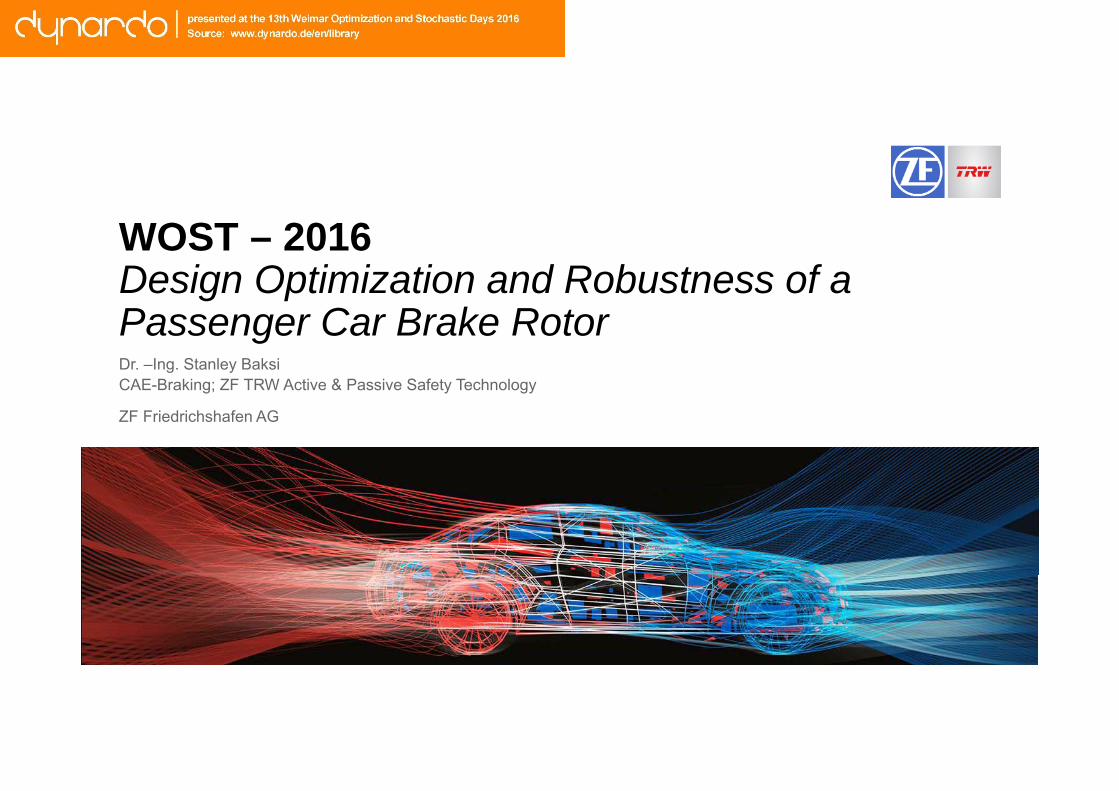
Contents
1. Background
2.
3.
4.
Motivation
Analysis and Solution
Robustness of Design
5. Conclusion
© ZF Friedrichshafen AG, 20152 CAE-Braking; ZF TRW Active & Passive Safety Technology, Presentation title11/10/2016
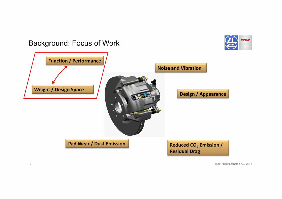
Background: Focus of Work
Noise and VibrationFunction / Performance
Weight / Design SpaceDesign / Appearance
Pad Wear / Dust Emission Reduced CO Emission /
© ZF Friedrichshafen AG, 20153
Pad Wear / Dust Emission Reduced CO2 Emission / Residual Drag
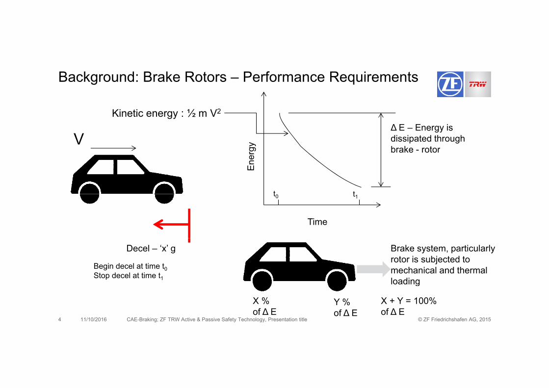
Background: Brake Rotors – Performance Requirements
V
Kinetic energy : ½ m V2
gy
∆ E – Energy is dissipated through brake - rotor
Ene
rg brake - rotor
t t
Time
t0 t1
Brake system, particularly rotor is subjected to mechanical and thermal loading
Decel – ‘x’ g
Begin decel at time t0Stop decel at time t1
© ZF Friedrichshafen AG, 20154 CAE-Braking; ZF TRW Active & Passive Safety Technology, Presentation title11/10/2016
X % of ∆ E
Y % of ∆ E
loading
X + Y = 100% of ∆ E
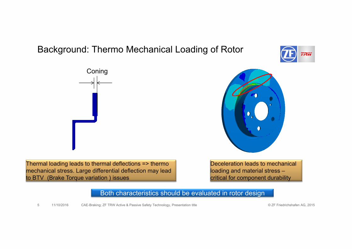
Background: Thermo Mechanical Loading of Rotor
Coning
Deceleration leads to mechanical loading and material stress –critical for component durability
Thermal loading leads to thermal deflections => thermo mechanical stress. Large differential deflection may lead to BTV (Brake Torque variation ) issues
© ZF Friedrichshafen AG, 20155 CAE-Braking; ZF TRW Active & Passive Safety Technology, Presentation title11/10/2016
Both characteristics should be evaluated in rotor design
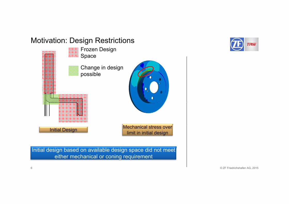
Motivation: Design RestrictionsFrozen Design Space
Change in design possible
Space
I iti l d i b d il bl d i did t t
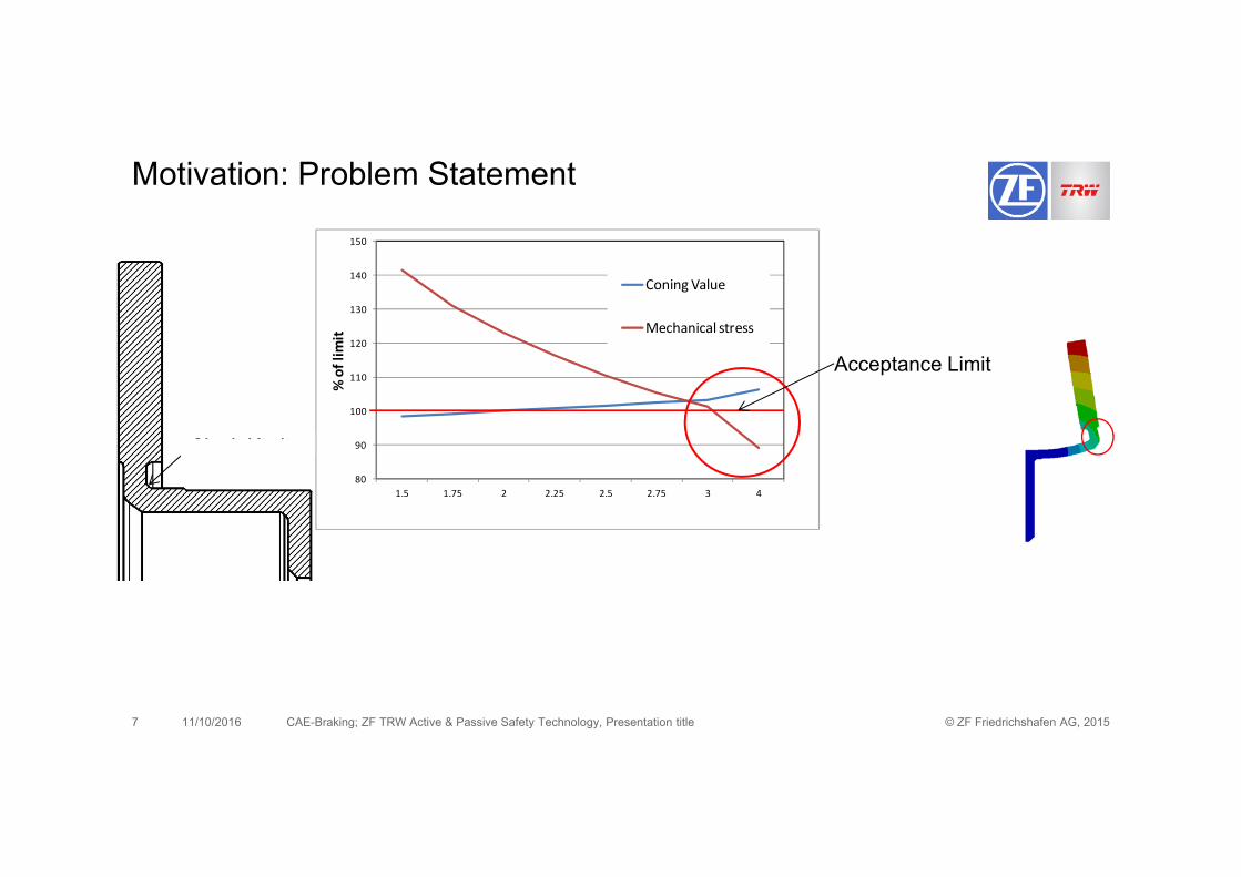
Initial Design Mechanical stress over limit in initial design
© ZF Friedrichshafen AG, 20156
Initial design based on available design space did not meet either mechanical or coning requirement
150
Motivation: Problem Statement
130
140
150
it
Coning Value
Mechanical stress
N k R di
100
110
120% of lim
i
Acceptance Limit
Neck Radius80
90
1.5 1.75 2 2.25 2.5 2.75 3 4
Neck Radius (mm)
© ZF Friedrichshafen AG, 20157 CAE-Braking; ZF TRW Active & Passive Safety Technology, Presentation title11/10/2016
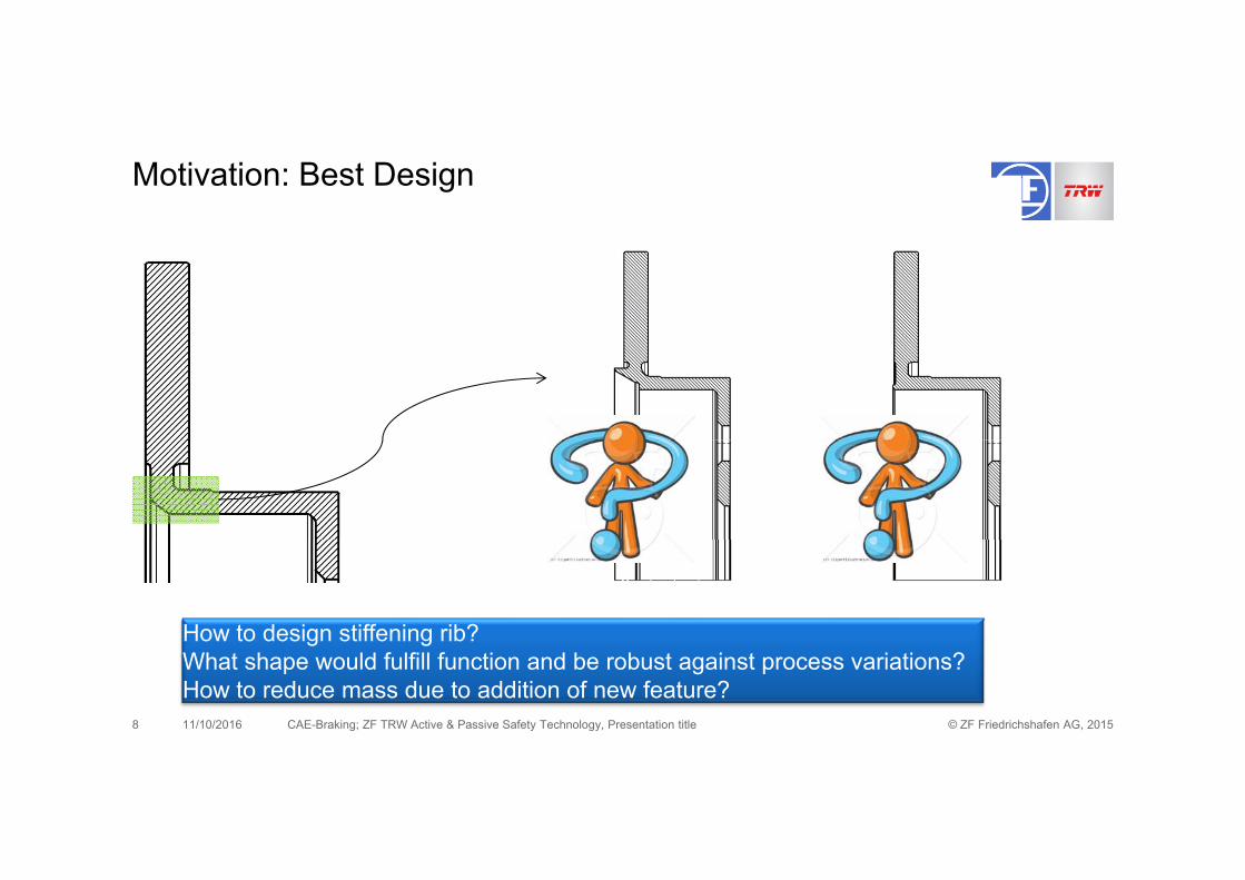
Motivation: Best Design
How to design stiffening rib?
© ZF Friedrichshafen AG, 20158 CAE-Braking; ZF TRW Active & Passive Safety Technology, Presentation title11/10/2016
How to design stiffening rib? What shape would fulfill function and be robust against process variations?How to reduce mass due to addition of new feature?
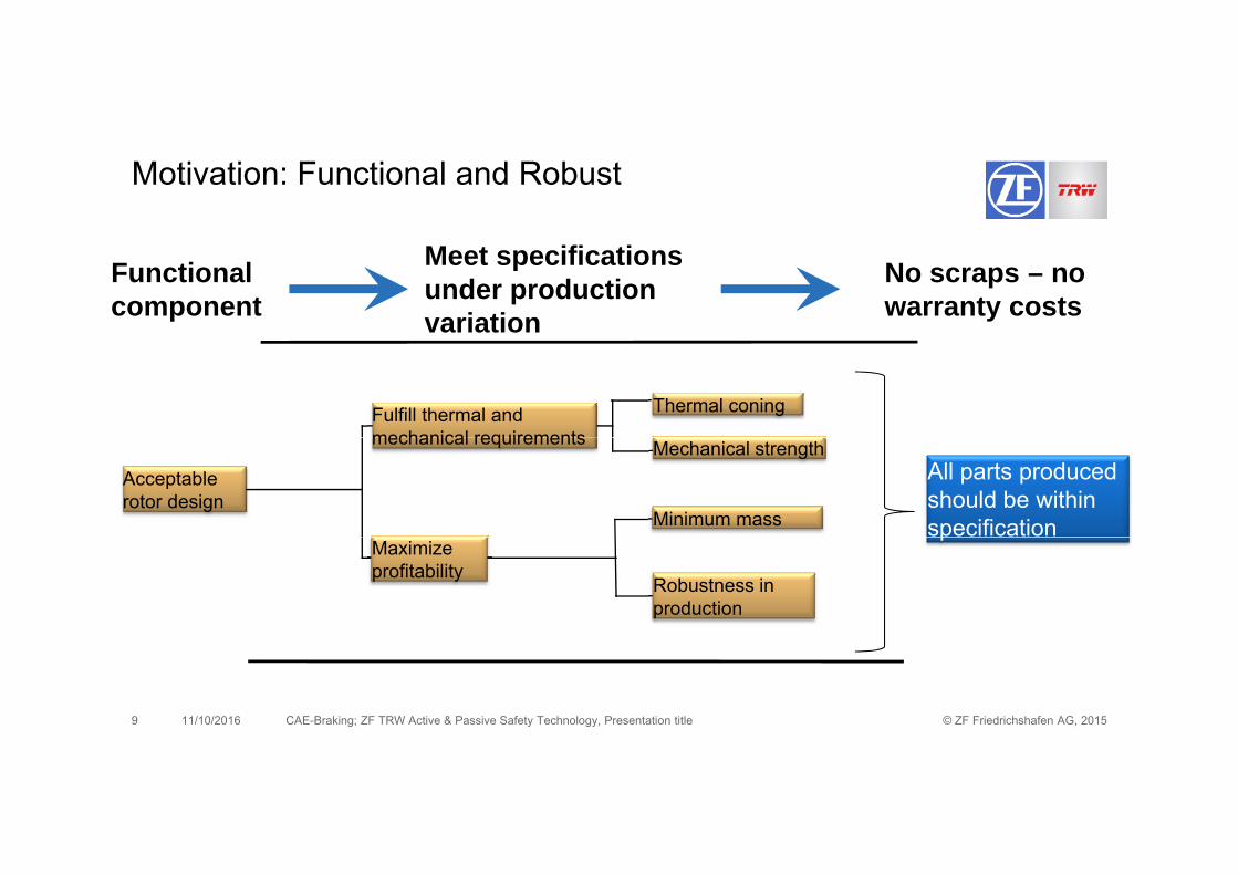
Motivation: Functional and Robust
Functional component
Meet specifications under production variation
No scraps – no warranty costs
Thermal coningFulfill thermal and mechanical requirements
Acceptable rotor design
Mechanical strength
Minimum mass
All parts produced should be within specification
mechanical requirements
Maximize profitability
Robustness in production
p
© ZF Friedrichshafen AG, 20159 CAE-Braking; ZF TRW Active & Passive Safety Technology, Presentation title11/10/2016
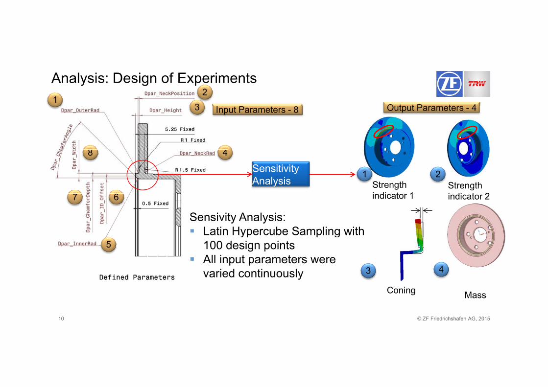
Analysis: Design of Experiments
O t t P t 41
23 Input Parameters - 8 Output Parameters - 43
48 48
Sensitivity Analysis
1 2Strength i di t 1
Strength i di t 2
Sensivity Analysis: Latin Hypercube Sampling with
67 indicator 1 indicator 2
y g100 design points
All input parameters were varied continuously
5
3 4
© ZF Friedrichshafen AG, 201510
Coning Mass
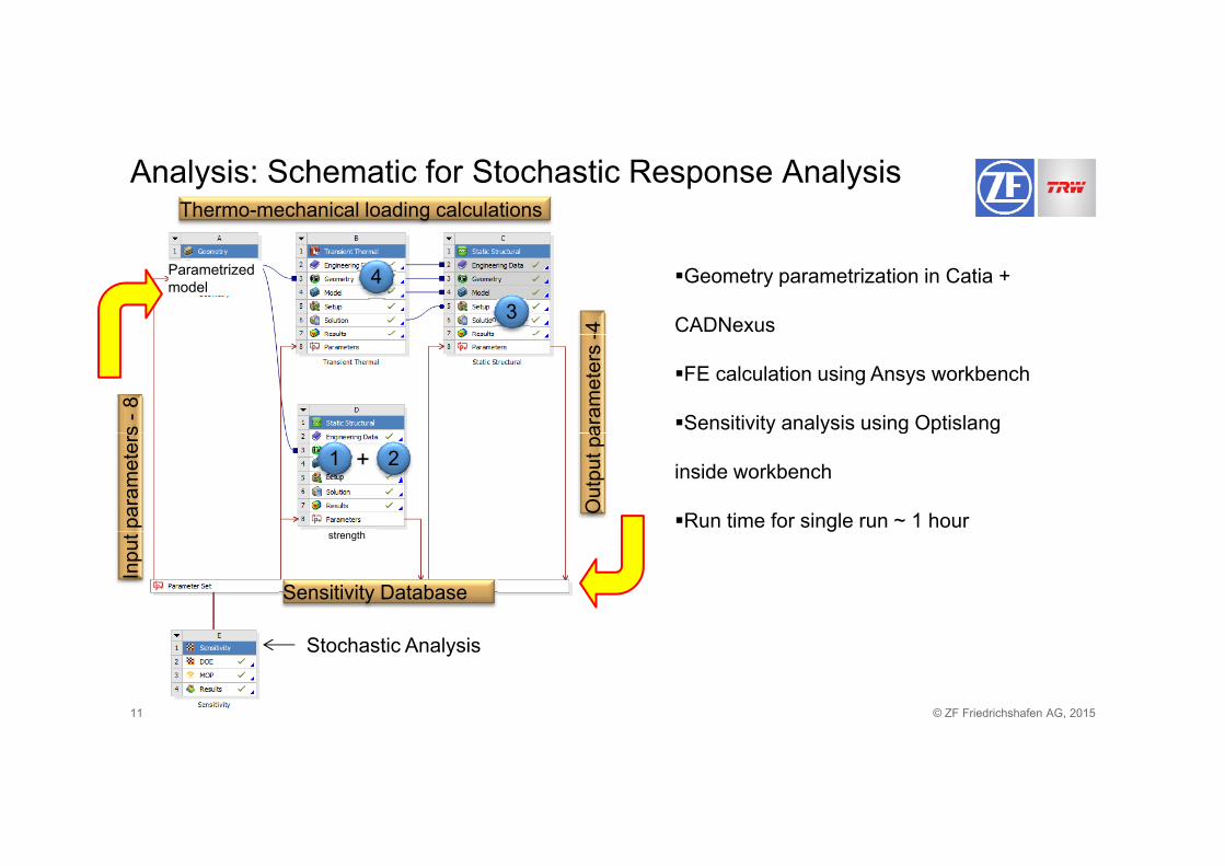
Analysis: Schematic for Stochastic Response AnalysisThermo-mechanical loading calculations
-4
Parametrizedmodel Geometry parametrization in Catia +
CADNexus3
4
s -8
aram
eter
s -
FE calculation using Ansys workbench
Sensitivity analysis using Optislang
para
met
ers
Out
put p
a
+y y g p g
inside workbench
Run time for single run ~ 1 hour
1 2
h
Inpu
t
Sensitivity Database
gstrength
© ZF Friedrichshafen AG, 201511
Stochastic Analysis
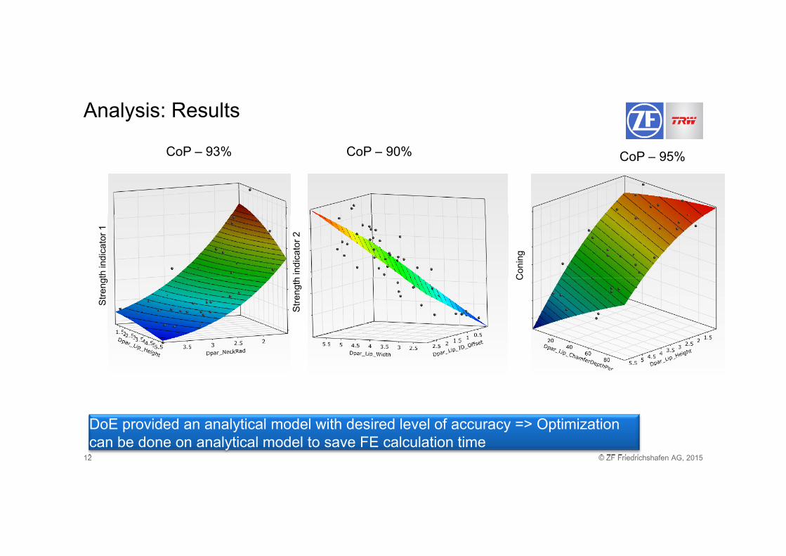
Analysis: Results
C P 95%CoP 93% CoP 90% CoP – 95%CoP – 93% CoP – 90%
Con
ing
th in
dica
tor 1
h in
dica
tor 2
C
Stre
ng
Stre
ngt h
© ZF Friedrichshafen AG, 201512
DoE provided an analytical model with desired level of accuracy => Optimization can be done on analytical model to save FE calculation time
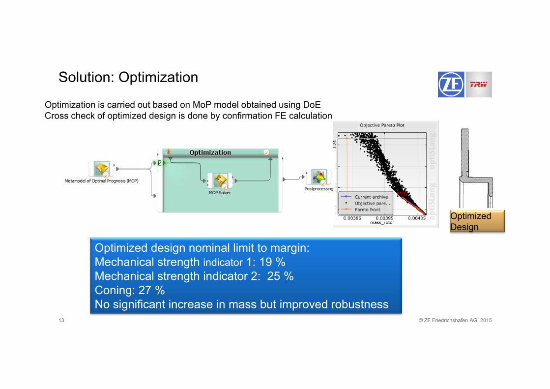
Solution: Optimization
Optimization is carried out based on MoP model obtained using DoEOptimization is carried out based on MoP model obtained using DoECross check of optimized design is done by confirmation FE calculation
Optimized Design
Optimized design nominal limit to margin: Mechanical strength indicator 1: 19 %Mechanical strength indicator 2: 25 %
© ZF Friedrichshafen AG, 201513
Coning: 27 %No significant increase in mass but improved robustness
25
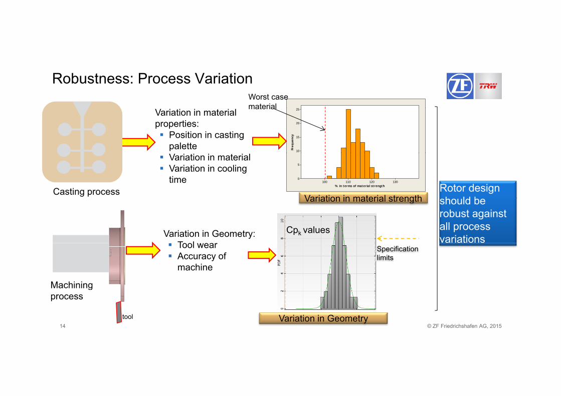
Robustness: Process VariationWorst case material 25
20
15
10Freq
uenc
y
Variation in material properties: Position in casting
palette
material
130120110100
5
0
% in terms of material strength
Variation in material strength
Variation in material Variation in cooling
timeCasting process Rotor design
h ld bVariation in material strength
Variation in Geometry: T l
should be robust against all process variations
Cpk values
Specification limits
Tool wear Accuracy of
machine
Machining
© ZF Friedrichshafen AG, 201514
Machining process
Variation in Geometrytool
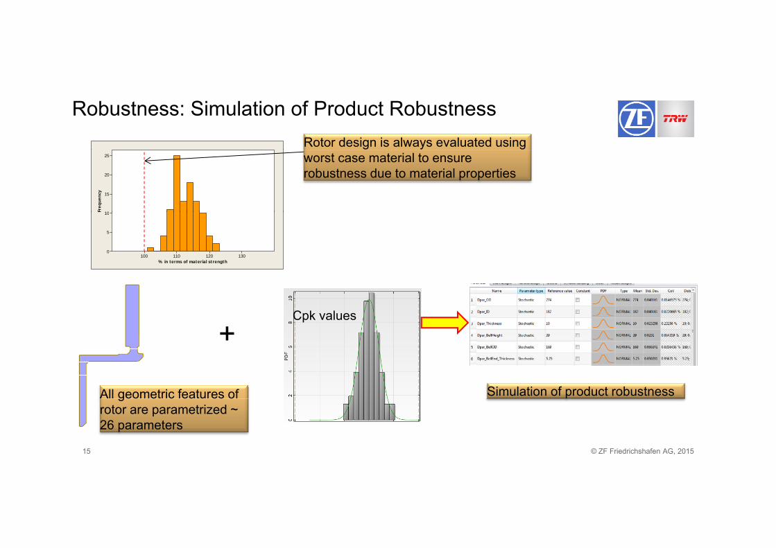
Robustness: Simulation of Product RobustnessRotor design is always evaluated using
25
20
15
10Freq
uenc
y
worst case material to ensure robustness due to material properties
130120110100
10
5
0
% in terms of material strength
F
Cpk values
+
All geometric features of
+
Simulation of product robustness
© ZF Friedrichshafen AG, 201515
geo e c ea u es orotor are parametrized ~ 26 parameters
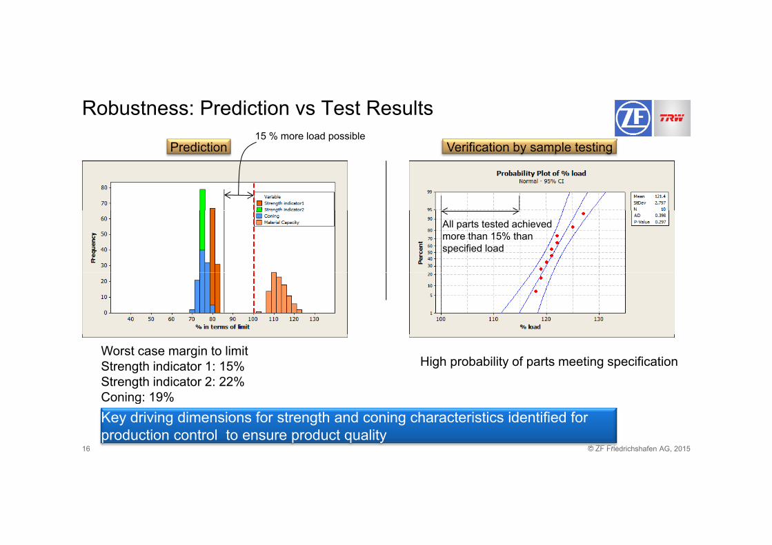
Robustness: Prediction vs Test Results
Prediction Verification by sample testing15 % more load possible
Prediction Verification by sample testing
All parts tested achieved more than 15% than specified load
High probability of parts meeting specificationWorst case margin to limitStrength indicator 1: 15%Strength indicator 2: 22%Coning: 19%
© ZF Friedrichshafen AG, 201516
Key driving dimensions for strength and coning characteristics identified for production control to ensure product quality
Coning: 19%
Summary
• Product requirements presented a design challenge • Detailed analysis was performed to understand key parameters drivingDetailed analysis was performed to understand key parameters driving
product performance• The product design was optimized to increase profit while meeting
i trequirements• Proposed optimized design to was analyzed to ensure robustness of
designdesign• Dimensions critical to quality were defined to ensure performance
under variation in production conditions
© ZF Friedrichshafen AG, 201517 CAE-Braking; ZF TRW Active & Passive Safety Technology, Presentation title11/10/2016
Thank you for your attention
© ZF Friedrichshafen AG, 201518ZF Friedrichshafen AG behält sich sämtliche Rechte an den gezeigten technischen Informationen einschließlich der Rechte zur Hinterlegung von Schutzrechtsanmeldungen und an daraus entstehenden Schutzrechten im In- und Ausland vor.ZF Friedrichshafen AG reserves all rights regarding the shown technical information including the right to file industrial property right applications and the industrial property rights resulting from these in Germany and abroad.