WORM GEARBOX -...
66
www.davidbrown.com Series BS (Compact Worm Gear) CBS-1.00GBD0108 WORM GEARBOX Technical Up to - 4 kW / 315 Nm
Transcript of WORM GEARBOX -...
www.davidbrown.com
Series BS(Compact Worm Gear)CB
S-1.00
GBD0
108
WORM GEARBOX
TechnicalUp to - 4 kW / 315 Nm

PRODUCTS IN THE RANGE
We can create custom engineered transmission solutions of any size and configuration.
Serving an entire spectrum of mechanical drive applications from food, energy, mining and metal; to automotive, aerospace and marine propulsion, we are here to make a positive difference to the supply of drive solutions.
DuoDriveDual gears on parallel output shafts
Series WPrecision right angle servo gearboxes
Series XTorque LimiterOverload protection device
Series BDScrewjack wormgear unit
Series FParallel angle helical bevel helical geared motors & reducers
Series KRight angle helical bevel helical geared motors & reducers
Series XGearTorsionally rigid,high torque coupling
Series BConex helicoidal gear geometry right angle gearmotors and reducers
Extruder DriveRugged duty reducer takes high screw pressure
Series JShaft mounted helical speed reducers
Series AWorm Gear units and geared motors in single & double reduction types
Series EEconomical planetary servo gearboxes
Series XCone RingPin and bush elastomer coupling
Series CRight angle drive helical worm geared motors & reducers
Series HLarge helical parallel shaft & bevel helical right angle drive units
Series PPrecision planetary servo gearboxes
Series XNyliconGear coupling with nylon sleeve
Series BSWorm gear unit
Series GHelical parallel shaft & bevel helical right angle drive gear units
Series MIn-line helical geared motors & reducers
Series XGridDouble flexing steel grid coupling
HTPHigh torque planetary gear units
Roloid Gear PumpLubrication and fluid transportation pump
We offer a wide range of repair services and many years experience of repairing demanding and highly critical transmissions in numerous industries.
SERIES BS

Contacts
AUSTRALIA
David Brown GearIndustries Ltd13-19 Franklin AvenueBulli, NSW 2516Australia
Tel: +61 2 4283 0300Fax: +61 2 4283 0333
CHINA
David Brown Gear Systems Trading (Shanghai) Co. LtdNo. 218 Xi Zhang South Road, Silver Tower, Suite 1204BShanghai 200021 P.R.China
Tel: +86 21 53966 555Fax: +86 21 53966 913
DENMARK
Benzler Transmission A/SFuglebævej 3DDK-2770 Kastrup, Danmark
Tel: +45 36 34 03 00Fax: +45 36 77 02 42
EUROPE
Benzler TBA BVJachthavenweg 2 NL-5928 NT Venlo
Netherlands & the rest of EuropeTel: +31 77 324 59 00Fax: +31 77 324 59 01 AustriaTel: +43 7 229 618 91Fax: +43 7 229 618 84 GermanyTel: 0800 350 40 00Fax: 0800 350 40 01
FINLAND
Oy Benzler ABVanha Talvitie 3CFI-00580 Helsingfors, Finland
Tel: +358 9 340 1716Fax: +358 9 340 1761
FRANCE
WECO Transmissions SA
Tel: +333 8937 0113Fax: +333 8937 3936
ITALY
David Brown Hydraulics Italia S.R.L.Via Del Costruttore, 6441058 – Vignola (MO)Italy
Tel: +39 059 770 0411Fax: +39 059 770 0425
SOUTH AFRICA
David BrownGear Industries Ltd12 Birmingham Street,Benoni Industrial1500South Africa
Tel: +27 11 748 0000Fax: +27 11 421 2553
SWEDEN & NORWAY
AB BenzlersBox 922 (Landskronavägen 1)251 09 HelsingborgSweden
Tel: +46 42 18 68 00Fax: +46 42 21 88 03
THAILAND
David Brown (Thailand) Ltd700/43 Moo 6Amata Nakorn Industrial EstateTumbol KlongtumruMuang, Chonburi 20000Thailand
Tel: +66 3845 9044Fax: +66 3821 3655
UNITED KINGDOM
David Brown Gear Systems LtdPark RoadLockwood, HuddersfieldWest Yorkshire, HD4 5DD
Tel: +44 (0) 1484 465 610 Fax: +44 (0) 1484 465 586
USA
Cone Drive240 East 12th StreetTraverse CityMichigan 49684USA
Tel: +1 888 994 2663Fax: +1 888 907 2663
www.davidbrown.comwww.benzlers.com
SERIES BS

www.davidbrown.com

Contents
Technical information ................................ 5Selection of worm gears andworm geared motors.................................. 6Order procedure .......................................10Mounting positions..................................... 11
WORM GEARED MOTORSPower ratings - Output speeds......................12Applications........ ..................................... 25Dimensions .............................................. 26
WORM GEARSPower ratings - Output speeds..................... 40Dimensions............................................... 48Maximum input speed .............................. 57Gear with Environmental classification ....... 58Combinationexamples .............................. 60CAD ...................................................... 61Mounting and maintenance instructions ...... 62Questionnaire........................................... 63
3

BENZLERS BENZLERS
BENZLERS
The programme
4
BENZLERS
BENZLERS
BS 40-71 BS 40-71 BS 88-112
Single input shaft Hollow shaft Single input shaft
BS 40-71 BS 40-71 BS 88-112
Output shaft Motorflange Hollow shaft
BS 40-71 BS 88-112 BS 88-112
Feet Feet Horizontal
BS 40-71 BS 40-71 BS 88-112
Bolt the gear to awall or foundationwithout feet or flange
Output flange Output flange
BS 40-71 BS 40-71 BS 88-112
Double input shaft Double worm gears Double worm gears

5
Technical information
Benzler worm gears BS 35-71 have a symmetrical gear-housing manufactured in aluminium. BS 88 and 112 havea gearhousing of cast-iron.The worm wheel is made of centrifugal cast tinbronze andthe worm screw is case-hardened and ground.All motor connections are according to IEC-standard andfor BS 40-112 with elastic coupling. This means thefollowing advantages:
• The worm screw is mounted with two separate bearingsand are not connected with the motor bearings. Thismeans longer lifetime and a smoother drive..
• Soft start and stop with elastic coupling for size 40-112.
• No oil leakage in to the motor.
• Possibility to change motor without dismounting thegear..
• Any type of motor with IEC-flange can be used..
The worm geared motor is available for mounting on abase, flange or torque arm and can be installed in anyposition.The gear can be combined with Benzlers’ remainingrange of helical and worm gears to provide very lowoutput speeds. All data given in this catalogue applies toABB standard motors and Benzlers brake motors.
MotorflangesThe motorflanges up to IEC-size 112 are made ofaluminium and are available in B5 and B14, largermotorflanges are made of cast-iron and available in B5.A finished bore shaft coupling is always deliveredtogether with the motorflange.
FeetThe feet can be mounted without modification.
Output shaftSingle or double output shaft can be mounted into thehollow shaft. The output shafts are locked into positionwith keys and retaining rings. BS 88-112 has as standardexecution, a single output shaft or a hollow shaft.
Output flangeAn output flange can easily be mounted on to the gear.The BS 40-71 gear casing can also be mounted onto awall or foundation and bolted through the 4 bolt holes inthe gear casing.
Torque arm bracketThe hollow shaft gearboxes can be supplied with torquearm bracket and torque arm.
FanBS 88/112 have fan as an option.
PaintingBS35-71 is normally delivered without painting. BS 40-71can be delivered according to environmentalclassification M2-M3, see page 58-59.BS88-112 is normally delivered with standardpaint,which is an alkyd paint in Benzler blue colour (RAL5015).

6
Selection of gears and gearmotors
Power and torque ratings for gears on page 40-47 applyto service factor 1.0. Service factor for geared motors canbe found after the output speeds. Service factor 1.0 isvalid for continous operation 8 hours/day without shocksand with 10-200 starts per hour. The inertia of the drivenmachine is less than 20% of the electric motor.Occasional shock loads may not exceed 1.8 times thegear rating at service factor 1.0.
Determination of sizes1. Determine the demand power or torque, Pe or T2b
ratio (i) or output speed (n2).2. Based on type of load/driven machine, operating
hours/day and number of starts/hour, select servicefactor fb (page 6-7).
3. Calculate T2 ≥ T2b x fb.4. Choose gear on page 40-47 according to following:
T2 ≥ T2b x fb at required ratio (i) or speed (n2).Note the efficiency.For example BS40 ratio 6,67:1, code Aη = 86% at n1 = 1430 rpm.
5. Calculate P1 =Pe x fb x 1η
Choose a size larger motor Pm ≥ P1For example P1 ≥ 0,42 kW choose 0,55 kW.
6. Choose a worm gear motor on pages 12-24.For example BS40A with a motor size 80A4.
7. Check that occasional shock loads do not exceed 1.8times the gear rating at service factor 1.0. T2max ≥ T2 x 1,8
8. Check that the thrust and overhung loads are notexceeded.
9. Check that maximum input speeds and thermal ratingsare not exceeded.
10. For conditions other than above described, forinstance extreme environments, high inertiasystems or other, please contact your nearestBenzler office.
Formulas:
T2b = Pe x 9550 (Nm)n2
T2 ≥ T2b x fb (Nm)
P1 = Pe x fb x 1 (kW)η
Pm ≥ P1 (kW)
T2max ≥ T2 x 1,8 (Nm)
Je, red = Je xn2
2
( n1 ) (kgm2)
T2 = Output torque rating, Nm page 12-24, 40-47)
T2b = Demand torque, NmT2max = Occasional maximum torque, NmP1 = Demand input power, kWPe = Demand power driven machine, kWPm = Motor powern1 = Input speed, rpmn2 = Output speed, rpmfb = Service factorη = Efficiency of the gearJe, red = Reduced inertia, kgm2
Je = Inertia driven machine, kgm2
Jm = Inertia motor, kgm2
Load classification Description Moment of inertia Example
Je, red ≤ 0.2 x Jm Uniform loaded conveyors and elevators.I Centrifugal pumps and fans.
Machines with uniform load and no shocks Agitators and mixers for liquids andsemiliquids without solid particles.
Larger conveyors.Je, red ≤ JmReciprocating pumps with 3 or more cylinders.I a Machines with small shocks and Agitators and mixers for media with
small variations in load high viscosity and/or solid particles.
Je, red ≤ 3 x Jm Larger conveyors.II Reciprocating pumps with 3 or more cylinders.
Machines with moderate shocks and variable load Agitators and mixers for media withhigh viscosity and/or solid particles
Je, red ≤ 10 x Jm Heavy agitators and mixers.Reciprocating pumps with 1 or 2 cylinders.
III Machines with very heavy shocks and large masses Crushers, mills and presses.to be accelerated Vibrators and shakers

7
Daily operations in hours 4 hours 8 hours 16 hours 24 hours
Starts per hour <10 10-200 >200 <10 10-200 >200 <10 10-200 >200 <10 10-200 >200
Load classificationI 0.8 0.9 1.0 0.9 1.0 1.1 1.1 1.2 1.3 1.3 1.4 1.5
I a 1.1 1.2 1.3 1.1 1.3 1.5 1.3 1.5 1.6 1.4 1.6 1.8II 1.3 1.4 1.6 1.3 1.6 1.8 1.4 1.7 1.9 1.5 1.8 2.0III 1.5 1.6 1.8 1.6 1.8 2.0 1.7 1.9 2.1 1.8 2.0 2.2
Control pointsThe forces allowed on the gear shafts are determined bybearing life and strength on gear shafts and housing.Radial forces at no thrust loads.In the power ratings page12-24 max. allowed radial force on output shaft is givenfor each output speed. The value is only valid if the forceis applied at the centre of the output shaft.If the force isapplied at another position the allowed radial force isgiven by the following:
Radial forces
Bearing life: Fr,x = a Fr2(f + x)
Strength on shaft Fr,x = c Fr2x
Strength on Fr,x = d Fr2maxgear housing: (g + x)
Fr,x = Max. radial force (N)Fr2 = Radial force acc to power ratings (N).Fr2max = Upper limit, for radial force. Can not
be exceeded (N)a, d, f, g = Internal measures (mm)x = Distance to radial force (mm)c = Half shaft length (mm)
Ambient temperature factor ftFor other ambient temperatures then 20° C, always multiply the thermal rating with the following factors.
Service factor fb
°C Celsius - 40 - 30 - 20 - 10 +/- 0 10 20 30 40 50
ft 1.80 1.67 1.53 1.40 1.27 1.13 1.00 0.87 0.73 0.60
Fan factor ffIf the gearbox has no fan and the motor is not directly flanged to the gearbox, multiply the thermal rating with thefollowing factors.
Input speed n1 (rpm) 10 100 300 750 1 000 1 500 3 000
ff 1 0.95 0.74 0.63 0.65 0.69 0.77
Type/Size a c d f g Fr2max (N)
BS 35 77.5 18 88.0 59.5 70.0 2 00040 90.5 18 101.5 72.5 83.5 2 00050 96.5 21 110.0 75.5 89.0 2 70063 107.0 29 122.0 78.0 93.0 4 00071 127.5 29 142.5 98.5 113.5 5 00088 152.5 41 181.0 111.5 140.0 10 000
112 175.0 41 210.5 134.0 169.5 15 000
c�
x�
F�r,x�
F�r�

8
Overhung load
If a sprocket, gear wheel or pulley is mounted on a shaft,a load check must be made. The overhung load in middleof the shaft may not exceed values shown in tablesbelow. For calculation of minimum permissible diameterthe following formula should be used.
Dmin =2000 x T2b x fe x fb mm
Fr2T2b = Torque required (Nm)
T2b = Pe x 9 550
Nmn2
ReversingDynamic self locking means that a force applied on theoutput shaft of the gear can not continue to drive the gearwhen the motor has been stopped.Dynamic self locking is only possible at very high ratiosand low output speeds. None of the worm gearsproduced by BENZLERS is dynamic totally self locking.Static self locking means that a force applied on theoutput shaft of the gear can not start a movement.When driving loads with high inertia care must be takento achieve a braking time long enough to preventoverload on the gear.When a worm gear is used in an application with shortbraking time a worm gear that is "dynamically reversible"is normally the best selection.Information regarding lead angle for BENZLERS wormgears are given on the following page.
γ
≥25° Total reversing12° - 25° Statically reversible
Variable static self locking8° - 12° Quick return in case of vibrations
Dynamically reversibleStatically self locking
5° - 8° Return in case of vibrationsScant dynamic reversingStatically self locking
3°- 5° Slow movement return in case ofvibrations. Low dynamic reversingStatically self locking
1°- 3° No returnLow dynamic reversing
Pe = Power kW
n2 = Output speed (rpm)
Fr2 = Permissible overhung load (N)
fb = Service factor (tables page 7)
fe = 1.10 for sprockets= 1.30 for gearwheels= 1.50 for pulleys
Dmin = Minimum permissible diameter (mm)
Gear Ratio
Fr1 A B C D E F Fx G H I J K L M
BS 40 180 135 100 95 80 70 - 50 45 45 40 30 - -50 215 190 155 115 100 80 70 65 55 55 40 - - -63 385 305 255 210 165 155 125 115 100 100 75 45 - -71 400 350 285 240 180 150 - 115 100 100 60 45 - -88 925 635 470 405 335 305 - 235 200 200 190 145 100 65
112 1375 930 740 580 505 425 - 340 295 295 255 160 125 105
Ratio
Size A B C D E F Fx G H I J K L M
BS 35 1500 1500 1500 1500 1500 1500 150040 2000 2000 2000 2000 2000 2000 - 2000 2000 2000 2000 2000 - -50 2500 2500 2500 2500 2500 2500 2500 2500 2500 2500 2500 - - -63 3500 3500 3500 3500 3500 3500 3500 3500 3500 3500 3500 3500 - -71 4500 4500 4500 4500 4500 4500 - 4500 4500 4500 4500 4500 - - 88 7800 10000 10000 10000 10000 10000 - 10000 10000 - 10000 10000 10000 10000
112 10400 14700 15000 15000 15000 15000 - 15000 15000 - 15000 15000 15000 15000
Max overhung load in the middle of input shaft (N)
Max thrust load on output shaft (N)
Reversing as a function of the leadangle

9
i = Ratio z = Starts of worm shaft ηs = Starting efficiencyγ = Lead angle m = Module η = Running efficiency n1=1430 rpm
Maximum input speed
Size
n1, max 35 40 50 63 71 88 112i<60:1 112i>60:1
rpm 4500 6000 5500 5000 4500 4000 3000 3500
EfficiencyThe efficiency of the gear has to be considered when aworm gear or a worm geared motor is chosen. Forintermittent duties it is necessary to increase the motorpower to be able to compensate for the low efficiencyduring start.Also consider that the highest efficiency is reached after
i γ z m ηs η
10 A 15.45 3 1.75 60 7915 B 10.45 2 1.75 51 74
B S 20 C 7.13 2 1.25 43 643 5 25 D 5.71 1 2.0 37 60
30 E 5.26 1 1.75 36 6040 F 3.58 1 1.25 27 4850 G 2.86 1 1.0 23 42
6.67 A 15.52 3 2.5 60 8610 B 16.70 3 2 62 8515 C 11.31 2 2 53 7920 D 8.53 1 3 47 75
B S 24 E 7.13 1 2.5 43 714 0 30 F 5.71 1 2 37 67
40 G 4.02 1 1.45 30 5948 H 3.58 1 1.25 27 5660 I 2.86 1 1 23 4970 J 3.03 1 0.9 24 4484 K 2.53 1 0.75 21 36
8 A 17.82 3 3 63 8810.5 B 15.07 2 3.5 60 87
14 C 12.19 2 2.7 55 8421 D 7.67 1 3.5 44 77
BS 24 E 7.07 1 3 39 745 0 32 F 5.71 1 2.4 37 71
37 FX 4.40 1 2 32 6642 G 4.29 1 1.8 31 6554 H 3 34 1 1.4 26 5964 I 2.99 1 1.2 24 5580 J 2.86 1 1 23 49
7.75 A 18.43 4 3 64 9011 B 17.82 3 3 63 8814 C 15.07 2 3.5 60 8718 D 10.20 2 2.7 51 83
24.5 E 9 93 2 2.1 50 81B S 29 F 7.67 1 3 5 44 776 3 37 FX 4 47 1 2.5 32 70
43 G 5 71 1 2.4 37 7151 H 4.76 1 2 33 6757 I 4.29 1 1.8 31 6573 J 3.34 1 1.4 26 59
104 K 2.60 1 1 22 46
run-in period and under continuous duty.All values given in the catalogue are only valid for a gearafter running-in period under continuous duty with servicefactor 1.If the gear is driven from the output shaft the back drivingefficiency is calculated as follows:
η - = 2 - 1η
i γ z m ηs η
7.5 A 18.29 4 3.5 64 929.33 B 19.98 3 4 65 91
12 C 14.04 3 3 58 8816 D 12.34 2 3.5 55 87
B S 21 E 10.20 2 2.7 51 8471 28 F 6.91 1 4 42 79
37 G 6.12 1 3 39 7648 H 4.73 1 2.4 33 7163 1 3.55 1 1.8 27 6582 J 2.86 1 1.4 23 58
100 K 2.99 1 1.2 24 54
7.25 A 21.80 4 4.5 67 9411.75 B 18.43 4 3 64 9115.67 C 14.04 3 3 58 8919.50 D 9.93 2 3.5 50 8723.50 E 9.46 2 3 49 85
B S 29 F 5.71 1 4.5 38 808 8 39 G 5.00 1 3.5 34 77
47 H 4.76 1 3 33 7558 J 4.47 1 2.5 32 7271 K 3.37 1 2 26 6782 L 3.55 1 1.8 27 66
106 M 2.86 1 1.4 23 57
7 A 22.48 4 6 68 9411.5 B 20.85 4 4 66 9315.3 C 15.95 3 4 61 9119.5 D 11.31 2 4.5 54 88
23 E 10.78 2 4 52 88B S 28 F 5.91 1 6 39 83112 39 G 5.71 1 4.5 38 80
46 H 5.44 1 4 36 7963 J 4.76 1 3 33 7576 K 4.21 1 2.5 31 7195 L 3.37 1 2 26 66
108 M 2 95 1 1.75 24 61
Benzlers Worm gear BS, Wormwheel and Wormscrew data

10
Questionaire
To specify a drive precisely certain data are essential. The most important questions are listed in the table below. If youdo not have the required data available in this form, we advice you to use a technical handbook or other suitabledocumentation. Should you have any question, please do not hesitate to contact us, Benzlers specialists will be pleasedto assist you.
Load designation
Output power (kW): Pe at nmax at nmin MotorEnclosure IP
Output speed (RPM): nemax neminOperating voltage motor (V) brake (V) frequency (Hz)
Output torque (Nm): Te at nmax at nminBrake torque (Nm)
Overhung load (N): Fr2e at output shaft at input shaftAmbient factorsAmbient temperature (°C)
Axial thrust load (N): Fa2e at output shaft at input shaft
(away + / towards -) Load cycle / Duty cycle S / % ED
Moment of inertia (kgm2): at output shaft at input shaft
Starting frequency (1/h)
Unit type and mounting position (see page 11)
Additional information:
Gears and geared motors are described by a code consisting of 10 positions. Positions that aren’t used are left empty.Additional information is written clearly.Example of such information is:Output speed, Motor powerConnecting voltage for motor and brake (if used)Type of motor at specific requestAll nonstandard executions that are not described in this catalogue.
Example on ordering text: (explanations, see page 11):
Gear Motor1 2 3 4 5 6 7 8 9 10BS 40 A 2,0H, M=115 - 4 80A4 - 180 B5
214 rpm 0,37 kW 220-240/380-420V, 50 Hz

11
1 Gear typeBS (Worm gear and worm geared motor)
2 Gear sizeStandard sizes 35,40, 50, 63, 71, 88, 112, 50/40, 63/40, 71/40, 88/50, 112/63Other combinations and sizes can be achieved. Check with Benzlers.
3 Ratio codeA, B, C....FA, FB, FC (2 letters for double wormgears).
4 Mounting positionSee picture *For execution - code 2 and 3 state flange size, for example M=115, see page 55.
5 Gear AccessoriesVM = distance ring for different position of terminal boxEB = brake on gearKEB = coupling/brake unit (specify type and voltage)F = fan on gear (only BS88 and BS112)DP = double input shaft
6 Input design2 = free high speed shaft (no motor or flange for
motor)3 = prepared for motor (specify flange and shaft
diametres or IEC-standard size)4 = with motor
7 MotorAcc. to IEC (71A, 71B)
8 Accessories for the motorB = BrakeTB = Thermostat protectionTh = Thermistor protectionFS = Fitted with forced coolingTG = TachogeneratorPG = Encoder
9 Terminal box positionPositions acc picture
10 MotorflangeB14 = Small flangeB5 = Large flange
Mounting positions
Position of terminal boxStandard position 0 Standard position 45
Motor flange B5Position of terminal box
Motor sizes
Motor flange B14
Position of terminal boxMotor sizes
* = Can be changed to 0 with distance ring, VM+ = Distance ring to be mounted on gearBS35 is not available with B5-flange.
63 71 80 90 100 112 132 160 180Gear
BS 40 45* 45* 45* 45*50 0 0 063 0 0 071 45+ 45+ 45+ 45+88 45 45 45 45 90
112(i<60) 45 45 90 45112(i>60) 45 45 45 90
63 71 80 90 100 112 132 160 180Gear
BS 35 45 4540 45* 45* 45* 45*50 45* 45* 45*63 45* 45* 45* 4571 0+ 0+ 0+ 0+88 0 0 0 0
112 0 0 0
BENZLERS
BENZLERS
BE
NZ
LE
RS
BE
NZ
LE
RS
BENZLERS
BENZLERS
BE
NZ
LE
RS
BENZLERS
0°�180°��
270°��
� 90°� �
135°� 45°�
225°��
315°��
Hollow shaft U O H-A H-BgearExecution - code 0
Feet and output OV OH ODshaftExecution - code 1
Only output UV UH UDshaftExecution - code 8
Only feet VV VH VDExecution - code 9 Endast Endast Endast
BS 40-71 BS 40-71 BS 40-71
Code 9 onlyHU-A HN-A HD-A
for BS40-71
HU-B HN-B HD-B
Output flange BS 35-71 BS 35-71 BS 88-112and shaft OH OV OHExecution - code 2*State M
Output flange BS 35-71 BS 35-71 BS 88-112and hollow shaft OH OV OHExecution - code 3*State M
Double gears P1 P2 P3(prestep gear isshown on picture)
P4 P5 P6
P7 P8
Execution - code 4
Gear with hollow O Vshaft, torque armand connectionExecution - code 5
BENZLERS
BENZLERS
BE
NZ
LE
RS
BENZLERS BE
NZ
LE
RS
Output Ratio Service Output Permissible Size Weight Dim.speed factor torque overhung load page
n2 i fbp T2 Fr2rpm Nm kN kg
0.69 1960.00 FJ 0.76 524 5.0 BS 71/40 63A-4 19 36-390.81 1680.00 Fl 0.86 463 5.01.01 1344.00 FH 0.99 403 5.01.21 1120.00 FG 1.13 354 5.01.62 840.00 FF 1.34 299 5.02.02 672.00 FE 1.57 255 5.02.43 560.00 FD 1.77 226 5.03.24 420.00 FC 2.20 182 5.04.86 280.00 FB 3.00 133 5.0
2.34 580.00 FD 0.76 234 4.0 BS 63/40 63A-4 16 36-393.13 435.00 FC 0.96 189 4.04.69 290.00 FB 1.33 138 4.07.03 193.43 FA 1.96 95 4.0
2.83 480.00 ED 1.30 113 2.7 BS 50/40 63A-4 14 36-393.78 360.00 EC 0.99 146 2.75.67 240.00 EB 1.33 108 2.78.50 160.00 EA 1.93 75 2.7
6.44 104.00 K 1.47 73 4.0 BS 63 71B-8 15 28-359.18 73.00 J 3.10 58 4.0
11.75 57.00 I 3.91 49 4.0
8.94 104.00 K 2.09 50 4.0 BS 63 71-6 13 28-35
8.38 80.00 J 1.24 62 2.7 BS 50 71B-8 13 28-3510.47 64.00 I 1.99 51 2.7
11.63 80.00 J 1.94 39 2.7 BS 50 71-6 11 28-3514.53 64.00 I 3.03 33 2.717.22 54.00 H 3.73 29 2.7
7.98 84.00 K 0.75 48 2.0 BS 40 71B-8 11 28-359.57 70.00 J 0.87 54 2.0
11.17 60.00 I 1.20 46 2.0
11.07 84.00 K 0.83 42 2.0 BS 40 71-6 9 28-3513.29 70.00 J 1.22 38 2.015.50 60.00 I 1.66 32 2.0
16.19 84.00 K 1.60 21 2.0 BS 40 63A-4 9 28-3519.43 70.00 J 2.36 19 2.022.67 60.00 I 3.21 16 2.028.33 48.00 H 4.15 14 2.034.00 40.00 G 4.84 12 2.045.33 30.00 F 5.97 10 2.056.67 24.00 E 7.07 8 2.068.00 20.00 D 8.18 7 2.090.67 15.00 C 10.53 6 2.0
136.00 10.00 B 14.84 4 2.0203.90 6.67 A 19.52 3 1.7
13.00 50.00 G .90 39 2.0 BS 35 71B-8 8.5 26-27 16.00 40.00 F 1.04 34 2.022.00 30.00 E 1.26 29 2.026.00 25.00 D 1.43 25 2.033.00 20.00 C 1.62 21 2.044.00 15.00 B 2.06 17 2.067.00 10.00 A 2.94 12 2.0
18.00 50.00 G 1.13 28 2.0 BS 35 71-6 7.0 26-2723.00 40.00 F 1.3 24 2.031.00 30.00 E 1.54 20 2.037.00 25.00 D 1.8 17 2.046.00 20.00 C 2.13 15 2.062.00 15.00 B 2.67 12 2.093.00 10.00 A 3.78 8 1.9
27.00 50.00 G 1.93 14 2.0 BS 35 63A-4 6.0 26-2734.00 40.00 F 2.23 12 2.0
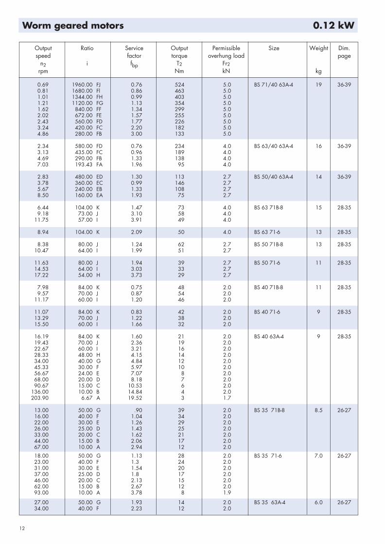
12
Worm geared motors 0.12 kW

Output Ratio Service Output Permissible Size Weight Dim.speed factor torque overhung load page
n2 i fbp T2 Fr2rpm Nm kN kg
45.00 30.00 E 2.70 10 2.0 BS 35 63A-4 6.0 26-27 54.00 25.00 D 3.16 8 2.068.00 20.00 C 3.8 7 2.090.00 15.00 B 4.78 5 2.0
136.00 10.00 A 6.84 4 1.7
13
Worm geared motors 0.12 kW
Worm geared motors 0.18 kW
Output Ratio Service Output Permissible Size Weight Dim.speed factor torque overhung load page
n2 i fbp T2 Fr2rpm Nm kN kg
1.22 1120.00 FG 0.76 529 5.0 BS 71/40 63B-4 19 36-391.63 840.00 FF 0.89 448 5.02.04 672.00 FE 1.04 383 5.02.45 560.00 FD 1.18 339 5.03.26 420.00 FC 1.46 274 5.04.89 280.00 FB 1.98 202 5.07.34 186.76 FA 2.91 137 5.0
4.72 290.00 FB 0.88 209 4.0 BS 63/40 63B-4 16 36-397.08 193.43 FA 1.29 144 4.0
5.71 240.00 EB 0.89 163 2.7 BS 50/40 63B-4 14 36-398.56 160.00 EA 1.27 114 2.7
6.60 106.00 M 2.35 123 10.0 BS 88 80A-8 51 28-35
7.00 100.00 K 1.40 118 5.0 BS 71 80A-8 21 28-358.54 82.00 J 2.15 100 5.011.11 63.00 I 3.71 83 5.0
6.73 104.00 K 0.92 117 4.0 BS 63 80A-8 18 28-359.59 73.00 J 1.94 92 4.0
8.85 104.00 K 1.19 88 4.0 BS 63 71A-6 14 28-3512.60 73.00 J 2.50 69 4.016.14 57.00 I 3.30 58 4.0
8.75 80.00 J 0.80 96 2.7 BS 50 80A-8 16 28-3510.94 64.00 I 1.28 80 2.712.96 54.00 H 1.67 72 2.7
11.50 80.00 J 1.10 68 2.7 BS 50 71A-6 12 28-3514.38 64.00 I 1.72 58 2.717.04 54.00 H 2.12 51 2.721.90 42.00 G 2.53 43 2.724.86 37.00 Fx 2.76 38 2.7
11.67 60.00 I 0.78 72 2.0 BS 40 80A- 8 14 28-35
15.33 60.00 I 0.99 54 2.0 BS 40 71A-6 10 28-3519.17 48.00 H 1.37 48 2.0
16.31 84.00 K 0.81 41 2.0 BS 40 63B-4 9 28-3519.57 70.00 J 1.19 37 2.022.83 60.00 I 1.62 32 2.028.54 48.00 H 2.09 28 2.034.25 40.00 G 2.44 24 2.045.67 30.00 F 3.01 20 2.057.08 24.00 E 3.56 16 2.068.50 20.00 D 4.12 14 2.091.33 15.00 C 5.31 11 2.0
137.00 10.00 B 7.48 8 2.0
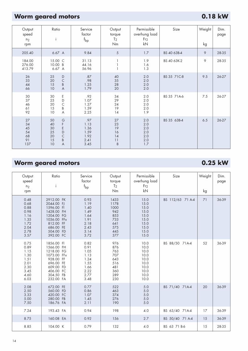
14
Worm geared motors 0.18 kW
Worm geared motors 0.25 kW
Output Ratio Service Output Permissible Size Weight Dim.speed factor torque overhung load page
n2 i fbp T2 Fr2rpm Nm kN kg
205.40 6.67 A 9.84 5 1.7 BS 40 63B-4 9 28-35
184.00 15.00 C 31.13 1 1.9 BS 40 63K-2 9 28-35276.00 10.00 B 44.16 1 1.6413.79 6.67 A 56.96 1 1.3
26 25 D .87 40 2.0 BS 35 71C-8 9.5 26-2733 20 C .98 35 2.044 15 B 1.25 28 2.066 10 A 1.79 20 2.0
30 30 E .92 34 2.0 BS 35 71A-6 7.5 26-2737 25 D 1.07 29 2.046 20 C 1.27 24 2.061 15 B 1.59 19 2.092 10 A 2.25 14 1.9
27 50 G .97 27 2.0 BS 35 63B-4 6.5 26-2734 40 F 1.13 23 2.045 30 E 1.36 19 2.054 25 D 1.59 16 2.068 20 C 1.92 14 2.091 15 B 2.41 11 2.0
137 10 A 3.45 8 1.7
Output Ratio Service Output Permissible Size Weight Dim.speed factor torque overhung load page
n2 i fbp T2 Fr2rpm Nm kN kg
0.48 2912.00 FK 0.93 1433 15.0 BS 112/63 71 A-4 71 36-390.68 2044.00 FJ 1.19 1178 15.00.88 1596.00 Fl 1.40 1000 15.00.98 1428.00 FH 1.49 942 15.01.16 1204.00 FG 1.64 853 15.01.35 1036.00 FFx 1.91 733 15.01.72 812.00 FF 2.18 641 15.02.04 686.00 FE 2.43 575 15.02.78 504.00 FD 3.14 445 15.03.57 392.00 FC 3.72 377 15.0
0.75 1856.00 Fl 0.82 976 10.0 BS 88/50 71A-4 52 36-390.89 1566.00 FH 0.91 876 10.01.15 1218.00 FG 1.05 763 10.01.30 1073.00 FFx 1.13 707 10.01.51 928.00 FF 1.24 643 10.02.01 696.00 FE 1.55 516 10.02.30 609.00 FD 1.66 481 10.03.45 406.00 FC 2.22 360 10.04.60 304.50 FB 2.77 289 10.06.03 232.00 FA 3.48 230 10.0
2.08 672.00 FE 0.77 522 5.0 BS 71/40 71A-4 20 36-392.50 560.00 FD 0.86 463 5.03.33 420.00 FC 1.07 374 5.05.00 280.00 FB 1.45 276 5.07.50 186.76 FA 2.11 190 5.0
7.24 193.43 FA 0.94 198 4.0 BS 63/40 71A-4 17 36-39
8.75 160.08 EA 0.92 156 2.7 BS 50/40 71 A-4 15 36-39
8.85 104.00 K 0.79 132 4.0 BS 63 71 B-6 15 28-35

15
Output Ratio Service Output Permissible Size Weight Dim.speed factor torque overhung load page
n2 i fbp T2 Fr2rpm Nm kN kg
12.60 73.00 J 1.67 104 4.0 BS 63 71 B-6 15 28-3516.14 57.00 I 2.21 87 4.018.04 51.00 H 2.29 80 4.021.40 43.00 G 2.32 72 4.0
13.46 104.00 K 1.30 77 4 0 BS 63 71A-4 14 28-3519.18 73.00 J 2.69 60 4.024.56 57.00 I 3.18 50 4.027.45 51.00 H 3.46 46 4.0
14.38 64.00 I 1.15 87 2.7 BS 50 71B 6 13 28-3517.04 54.00 H 1.42 77 2.7
17.50 80.00 J 1.07 66 2.7 BS 50 71A-4 12 28-3521.88 64.00 I 1.70 55 2.725.93 54.00 H 1.86 48 2.733.33 42.00 G 2.23 40 2.737.84 37.00 Fx 2.45 36 2.743.75 32.00 F 2.75 33 2.7
19.17 48.00 H 0.94 70 2.0 BS 40 71B 6 11 28-3523.00 40.00 G 1.12 61 2.0
20.00 70.00 J 0.77 57 2.0 BS 40 71A-4 10 28-3523.33 60.00 I 1.04 50 2.029.17 48.00 H 1.35 43 2.035.00 40.00 G 1.57 37 2.046.67 30.00 F 1.94 30 2.058.33 24.00 E 2.30 25 2.070.00 20.00 D 2.66 22 2.093.33 15.00 C 3.43 17 2.0
140.00 10.00 B 4.83 12 2.0209.90 6.67 A 6.35 8 1.7
183.33 15.00 C 9.36 5 1.9 BS 40 63B-2 9 28-35275.00 10.00 B 13.28 3 1.6412.29 6.67 A 17.13 2 1.3
46.00 20.00 C .87 35 2.0 BS 35 71B-6 8.5 26-2761.00 15.00 B 1.09 29 2.0 92.00 10.00 A 1.54 20 1.9
46.00 30.00 E .88 30 2.0 BS 35 71A-4 7.5 26-2756.00 25.00 D 1.03 25 2.070.00 20.00 C 1.24 21 2.093.00 15.00 B 1.55 17 2.0
140.00 10.00 A 2.23 12 1.7
275.00 10.00 A 5.93 3 1.3 BS 35 63-B2 6.5 26-27
Worm geared motors 0.25 kW
Worm geared motors 0.37 kW
Output Ratio Service Output Permissible Size Weight Dim.speed factor torque overhung load page
n2 i fbp T2 Fr2rpm Nm kN kg
0.68 2044.00 FJ 0.80 1747 15.0 BS 112/63 71B-4 72 36-390.88 1596.00 Fl 0.94 1483 15.00.98 1428.00 FH 1.00 1398 15.01.16 1204.00 FG 1.10 1267 15.01.35 1036.00 FFx 1.29 1089 15.01.72 812.00 FF 1.47 954 15.02.04 686.00 FE 1.64 856 15.02.78 504.00 FD 2.11 664 15.0

16
Worm geared motors 0.37 kW
Output Ratio Service Output Permissible Size Weight Dim.speed factor torque overhung load page
n2 i fbp T2 Fr2rpm Nm kN kg
2.78 504.00 FD 2.11 664 15.0 BS 112/63 71B-4 72 36-393.57 392.00 FC 2.49 563 15.04.55 308.00 FB 3.08 455 15.0
1.30 1073.00 FFx 0.76 1050 10.0 BS 88/50 71B-4 53 36-391.51 928.00 FF 0.84 954 10.02.01 696.00 FE 1.04 766 10.02.30 609.00 FD 1.12 716 10.03.45 406.00 FC 1.49 536 10.04.60 304.50 FB 1.86 431 10.06.03 232.00 FA 2.33 344 10.0
5.00 280.00 FB 0.97 411 5.0 BS 71/40 71B-4 21 36-397.50 186.76 FA 1.41 284 5.0
6.48 108.00 M 1.92 294 15.0 BS 112 90S-8 71 28-357.37 95.00 L 2.53 271 15.0
6.60 106.00 M 1.00 288 10.0 BS 88 90S 8 54 28-358.54 82.00 L 1.74 241 10.09.86 71.00 K 2.38 212 10.0
8.68 106.00 M 1.30 216 10.0 BS 88 80A-6 50 28-3511.22 82.00 L 2.27 180 10.012.96 71.00 K 3.15 156 10.0
8.54 82.00 J 0.95 228 5.0 BS 71 90S-8 24 28-35
9.20 100.00 K 0.78 207 5.0 BS 71 80A-6 20 28-3511.22 82.00 J 1.22 172 5.014.60 63.00 I 1.97 143 5.019.17 48.00 H 2.37 118 5.0
9.59 73.00 J 0.85 210 4.0 BS 63 90S-8 21 28-35
12.60 73.00 J 1.07 163 4.0 BS 63 80A-6 17 28-3516.14 57.00 I 1.41 137 4.018.04 51.00 H 1.46 126 4.0
13.46 104.00 K 0.77 130 4.0 BS 63 71B-4 15 28-3519.18 73.00 J 1.60 101 4.024.56 57.00 I 1.88 85 4.027.45 51.00 H 2.05 78 4.032.56 43.00 G 2.34 68 4.037.84 37.00 Fx 2.56 57 4.048.28 29.00 F 3.18 49 4.0
12.96 54.00 H 0.76 159 2.7 BS 50 90S-8 19 28-35
17.04 54.00 H 0.90 121 2.7 BS 50 80A 6 15 28-35
21.88 64.00 I 1.04 89 2.7 BS 50 71B-4 13 28-3525.93 54.00 H 1.14 79 2.733.33 42.00 G 1.37 66 2.737.84 37.00 Fx 1.50 59 2.743.75 32.00 F 1.68 53 2.758.33 24.00 E 2.07 41 2.766.67 21.00 D 2.33 37 2.7
100.00 14.00 C 3.34 26 2.7
29.17 48.00 H 0.83 70 2.0 BS 40 71B-4 11 28-3535.00 40.00 G 0.97 60 2.046.67 30.00 F 1.19 50 2.058.33 24.00 E 1.41 41 2.0
89.00 10.00 A .96 32 1.9 BS 35 71C-6 9.5 26-27
93.00 15.00 B .95 27 2.0 BS 35 71B-4 8.5 26-27140.00 10.00 A 1.37 19 1.7282.00 10.00 A 2.77 7 1.3 BS 35 71A-2 7.5 26-27

17
Output Ratio Service Output Permissible Size Weight Dim.speed factor torque overhung load page
n2 i fbp T2 Fr2rpm Nm kN kg
1.36 1036.00 FFx 0.87 1612 15.0 BS 112/63 80A-4 74 36-391.74 812.00 FF 0.99 1412 15.02.06 686.00 FE 1.10 1268 15.02.80 504.00 FD 1.42 985 15.03.60 392.00 FC 1.67 836 15.04.58 308.00 FB 2.07 677 15.06.50 217.00 FA 2.73 514 15.0
2.32 609.00 FD 0.75 1060 10.0 BS 88/50 80A-4 55 36-393.47 406.00 FC 1.01 795 10.04.63 304.50 FB 1.25 639 10.06.08 232.00 FA 1.57 511 10.0
7.55 186.76 FA 0.94 424 5.0 BS 71/40 80A-4 23 36-39
6.48 108.00 M 1.22 461 15.0 BS 112 90L-8 74 28-357.37 95.00 L 1.61 425 15.09.21 76.00 K 2.35 366 15.0
8.54 82.00 L 1.13 372 10.0 BS 88 90L-8 57 28-359.86 71.00 K 1.54 327 10.0
8.68 106.00 M 0.82 341 10.0 BS 88 80B-6 51 28-3511.22 82.00 L 1.44 285 10.012.96 71.00 K 2.00 246 10.015.86 58.00 J 2.59 216 10.0
13.30 106.00 M 1.22 221 10.0 BS 88 80A-4 50 28-3517.20 82.00 L 2.12 184 10.0 19.86 71.00 K 2.74 159 10.024.31 58.00 J 3.51 139 10.0
11.11 63.00 I 1.07 290 5.0 BS 71 90L-8 27 28-35
11.22 82.00 J 0.78 269 5.0 BS 71 80B-6 21 28-3514.60 63.00 I 1.26 223 5.019.17 48.00 H 1.52 185 5.0
17.20 82.00 J 1.14 177 5.0 BS 71 80A 4 20 28-3522.38 63.00 I 1.60 146 5.029.38 48.00 H 1.97 119 5.0 38.11 37.00 G 2.47 96 5.050.36 28.00 F 2.97 76 5.067.14 21.00 E 3.87 59 4.6
16.14 57.00 I 0.91 212 4.0 BS 63 80B-6 18 28-3518.04 51.00 H 0.94 195 4.0 21.40 43.00 G 0.96 173 4.0
19.32 73.00 J 1.00 162 4.0 BS 63 80A-4 17 28-3524.74 57.00 I 1.18 136 4.027.65 51.00 H 1.28 125 4.032.79 43.00 G 1.46 109 4.038.11 37.00 Fx 1.60 92 4.048.62 29.00 F 1.99 78 4.057.55 24.50 E 2.33 69 4.078.33 18.00 D 2.92 51 3.9
33.57 42.00 G 0.87 103 2.7 BS 50 80A-4 15 28-3538.11 37.00 Fx 0.96 92 2.744.06 32.00 F 1.07 84 2.758.75 24.00 E 1.32 65 2.767.14 21.00 D 1.49 59 2.7
100.71 14.00 C 2.13 41 2.7134.29 10.50 B 2.74 32 2.7176.25 8.00 A 3.40 24 2.4
201.43 14.00 C 3.82 17 2.5 BS 50 71B-2 13 28-35
58.75 24.00 E 0.90 65 2.0 BS 40 80A-4 13 28-35
Worm geared motors 0.55 kW

18
Output Ratio Service Output Permissible Size Weight Dim.speed factor torque overhung load page
n2 i fbp T2 Fr2rpm Nm kN kg
70.50 20.00 D 1.04 56 2.0 BS 40 80A-4 13 28-3594.00 15.00 C 1.34 43 2.0
141.00 10.00 B 1.89 30 2.0211.39 6.67 A 2.48 20 1.7
188.00 15.00 C 2.40 18 1.9 BS 40 71B-2 11 28-35282.00 10.00 B 3.41 13 1.6422.79 6.67 A 4.40 8 1.3
138.00 10.00 A 0.85 31 1.7 BS 35 71C-4 9.5 26-27
282.00 10.00 A 1.52 12 1.3 BS 35 71B-2 8.5 26-27
Worm geared motors 0.55 kW
Worm geared motors 0.75 kW
Output Ratio Service Output Permissible Size Weight Dim.speed factor torque overhung load page
n2 i fbp T2 Fr2rpm Nm kN kg
2.06 686.00 FE 0.81 1733 15.0 BS 112/63 80B-4 75 36-392.80 504.00 FD 1.04 1347 15.0 3.60 392.00 FC 1.22 1144 15.0 4.58 308.00 FB 1.51 928 15 0 6.50 217.00 FA 1.99 705 15.0
4.63 304.50 FB 0.92 874 10.0 BS 88/50 80B-4 56 36-396.08 232.00 FA 1.14 699 10.0
6.48 108.00 M 0.87 647 15.0 BS 112 100LA 8 80 28-357.37 95.00 L 1.15 596 15.0 9.21 76.00 K 1.67 513 15.0
8.52 108.00 M 1.10 497 15.0 BS 112 90S-6 71 28-359.68 95.00 L 1.46 457 15.0
12.11 76.00 K 2.19 393 15.0 14.60 63.00 J 2.96 339 15.0
8.54 82.00 L 0.81 518 10.0 BS 88 100LA-8 62 28-359.86 71.00 K 1.11 455 10.0
11.22 82.00 L 1.02 400 10.0 BS 88 90S-6 54 28-3512.96 71.00 K 1.42 347 10.0 15.66 58.00 J 1.84 304 10.0
13.30 106.00 M 0.85 318 10.0 BS 88 80B-4 51 28-3517.20 82.00 L 1.48 264 10.019.86 71.00 K 1.91 229 10.024.31 58.00 J 2.44 200 10.030.00 47.00 H 3.06 166 10.036.15 39.00 G 3.76 140 10.0
14.58 48.00 H 0.91 339 5.0 BS 71 100LA-8 31 28-35
19.17 48.00 H 1.09 259 5.0 BS 71 90S-6 24 28-35
17.20 82.00 J 0.80 251 5.0 BS 71 80B-4 21 28-3522.38 63.00 I 1.13 207 5.029.38 48.00 H 1.38 169 5.038.11 37.00 G 1.74 137 5.050.36 28.00 F 2.09 108 5.067.14 21.00 E 2.72 85 4.688.13 16.00 D 3.40 66 4.0

19
Worm geared motors 0.75 kW
Output Ratio Service Output Permissible Size Weight Dim.speed factor torque overhung load page
n2 i fbp T2 Fr2rpm Nm kN kg
24.74 57.00 I 0.83 193 4.0 BS 63 80B-4 18 28-3527.65 51.00 H 0.90 177 4.032.79 43.00 G 1.03 155 4 038.11 37.00 Fx 1.13 130 4 048.62 29.00 F 1.40 111 4.057.55 24.50 E 1.64 97 4.078.33 18.00 D 2.06 72 3.9
100.71 14.00 C 2.64 58 3.4128.18 11.00 B 3.22 46 3.0
158.33 18.00 D 3.59 31 3.1 BS 63 80A-2 17 28-35
44.06 32.00 F 0.76 118 2.7 BS 50 80B-4 16 28-3558.75 24.00 E 0.94 91 2.767.14 21.00 D 1.06 82 2.7
100.71 14.00 C 1.51 58 2.7134.29 10.50 B 1.95 45 2.7176.25 8.00 A 2.41 34 2.4
203.57 14.00 C 2.58 26 2.5 BS 50 80A-2 15 28-35271.43 10.50 B 3.31 20 2.2
94.00 15.00 C 0.95 61 2.0 BS 40 80B-4 14 28-35141.00 10.00 B 1.34 43 2.0 211.39 6.67 A 1.76 28 1.7
190.00 15.00 C 1.62 27 1.9 BS 40 80A-2 13 28-35285.00 10.00 B 2.30 19 1.6427.29 6.67 A 2.97 12 1.3
282.00 10.00 A 1.02 19 1.3 BS 35 71C-2 9.5 26-27

Output Ratio Service Output Permissible Size Weight Dim.speed factor torque overhung load page
n2 i fbp T2 Fr2rpm Nm kN kg
3.60 392.00 FC 0.83 1683 15.0 BS 112/63 90S-4 78 36-394.58 308.00 FB 1.03 1366 15.06.50 217.00 FA 1.35 1039 15.0
7.37 95.00 L 0.76 895 15.0 BS 112 100LB-8 83 28-359.21 76.00 K 1.11 770 15.0
9.68 95.00 L 0.96 692 15.0 BS 112 90L-6 74 28-3512.11 76.00 K 1.45 594 15.0
14.60 63.00 J 1.96 513 15.0 BS 112 90L-6 74 28-35
13.06 108.00 M 1.06 495 15.0 BS 112 90S-4 71 28-3514.84 95.00 L 1.40 454 15.018.55 76.00 K 2.17 383 15.022.38 63.00 J 2.65 330 15.0
12.96 71.00 K 0.94 522 10.0 BS 88 90L-6 57 28-3515.86 58.00 J 1.22 458 10.0
17.20 82.00 L 0.97 404 10.0 BS 88 90S-4 54 28-3519.86 71.00 K 1.25 350 10.024.31 58.00 J 1.60 306 10.030.00 47.00 H 2.00 254 10.036.15 39.00 G 2.46 213 10.048.62 29.00 F 3.18 165 9.760.00 23.50 E 3.39 141 9.0
29.38 48.00 H 0.91 257 5.0 BS 71 90S 4 24 28-3538.11 37.00 G 1.14 208 5.050.36 28.00 F 1.38 163 5.067.14 21.00 E 1.79 128 4.6 88.13 16.00 D 2.24 100 4.0
117.50 12.00 C 2.84 76 3.5 151.13 9.33 B 3.62 60 3.0
48.62 29.00 F 0.92 169 4.0 BS 63 90S-4 21 28-3557.55 24.50 E 1.08 148 4.078.33 18.00 D 1.35 110 3.9
100.71 14.00 C 1.74 88 3.4128.18 11.00 B 2.12 70 3.0 181.94 7.75 A 2.68 50 2.6
158.33 18.00 D 2.22 50 3.1 BS 63 80B-2 18 28-35203.57 14.00 C 2.86 40 2.7 259.09 11.00 B 3.51 32 2.4
100.71 14.00 C 1.00 88 2.7 BS 50 90S-4 19 28-35134.29 10.50 B 1.29 67 2.7176.25 8.00 A 1.60 52 2.4
203.57 14.00 C 1.63 41 2.5 BS 50 80B-2 16 28-35271.43 10.50 B 2.09 31 2.2 356.25 8.00 A 2.59 24 1.9
285.00 10.00 B 1.45 30 1.6 BS 40 80B-2 14 28-35427.29 6.67 A 1.87 20 1.3
20
Worm geared motors 1.1 kW

Output Ratio Service Output Permissible Size Weight Dim.speed factor torque overhung load page
n2 i fbp T2 Fr2rpm Nm kN kg
4.61 308.00 FB 0.76 1853 15.0 BS 112/63 90L 4 81 36-396.54 217.00 FA 0.99 1411 15.0
9.08 76.00 K 0.79 1080 15.0 BS 112 112M-8 91 28-35
12.37 76.00 K 1.07 807 15.0 BS 112 100L-6 83 28-3514.92 63.00 J 1.44 697 15.0
13.15 108.00 M 0.76 692 15.0 BS 112 90L-4 74 28-3514.95 95.00 L 1.00 635 15.018.68 76.00 K 1.55 536 15.022.54 63.00 J 1.89 462 15.030.87 46.00 H 2.78 350 15.036.41 39.00 G 3.19 300 15.0
16.21 58.00 J 0.90 620 10.0 BS 88 100L-6 65 28-35
20.00 71.00 K 0.90 485 10.0 BS 88 90L-4 57 28-3524.48 58.00 J 1.15 424 10.030.21 47.00 H 1.44 352 10.036.41 39.00 G 1.77 296 10.048.97 29.00 F 2.30 228 9.760.43 23.50 E 2.44 196 9.072.82 19.50 D 3.01 165 8.290.62 15.67 C 3.56 135 7.4
50.71 28.00 F 1.00 225 5.0 BS 71 90L-4 27 28-3567.62 21.00 E 1.30 177 4.688.75 16.00 D 1.62 138 4.0
118.33 12.00 C 2.05 105 3.5152.20 9.33 B 2.62 83 3.0189.33 7.50 A 2.97 68 2.7
238.33 12.00 C 3.25 49 2.9 BS 71 90S-2 24 28-35
57.96 24.50 E 0.78 204 4.0 BS 63 90L-4 24 28-3578.89 18.00 D 0.98 152 3.9
101.43 14.00 C 1.26 122 3.4 129.09 11.00 B 1.54 97 3.0183.23 7.75 A 1.94 69 2.6
158.89 18.00 D 1.55 71 3.1 BS 63 90S-2 21 28-35204.29 14.00 C 2.00 57 2.7 260.00 11.00 B 2.46 46 2.4369.03 7.75 A 3.11 32 2.1
135.24 10.50 B 0.94 93 2.7 BS 50 90L-4 22 28-35177.50 8.00 A 1.16 71 2.4
204.29 14.00 C 1.15 57 2.5 BS 50 90S-2 19 28-35272.38 10.50 B 1.48 44 2.2357.50 8.00 A 1.83 34 1.9
21
Worm geared motors 1.5 kW

22
Worm geared motors 2.2 kW
Worm geared motors 3 kW
Output Ratio Service Output Permissible Size Weight Dim.speed factor torque overhung load page
n2 i fbp T2 Fr2rpm Nm kN kg
14.76 63.00 J 0.96 1048 15.0 BS 112 112M-6 91 28-35
18.82 76.00 K 1.04 802 15.0 BS 112 100LA-4 81 28-3522.70 63.00 J 1.26 691 15.031.09 46.00 H 1.86 524 15.036.67 39.00 G 2.13 450 15.051.07 28.00 F 2.70 331 15.062.17 23.00 E 3.23 288 13.6
30.43 47.00 H 0.97 523 10.0 BS 88 100LA-4 63 28-3536.67 39.00 G 1.19 440 10.049.31 29.00 F 1.54 339 9.760.85 23.50 E 1.64 291 9.073.33 19.50 D 2.03 245 8.291.26 15.67 C 2.39 201 7.4121.70 11.75 B 3.18 154 6.3
89.38 16.00 D 1.10 204 4.0 BS 71 100LA-4 32 28-35119.17 12.00 C 1.39 155 3.5153.27 9.33 B 1.77 123 3.0190.67 7.50 A 2.01 100 2.7
239.17 12.00 C 2.13 75 2.9 BS 71 90L-2 27 28-35307.61 9.33 B 2.74 60 2.4382.67 7.50 A 3.15 48 2.2
102.14 14.00 C 0.85 181 3.4 BS 63 100LA-4 29 28-35130.00 11.00 B 1.04 144 3.0184.52 7.75 A 1.31 102 2.6
205.00 14.00 C 1.31 88 2.7 BS 63 90L-2 24 28-35260.91 11.00 B 1.61 70 2.4370.32 7.75 A 2.04 50 2.1
358.75 8.00 A 1.21 51 1.9 BS 50 90L-2 22 28-35
22.70 63.00 J 0.91 957 15.0 BS 112 100LB-4 84 28-3531.09 46.00 H 1.34 726 15.036.67 39.00 G 1.54 623 15.051.07 28.00 F 1.95 458 15.062.17 23.00 E 2.33 398 13.673.33 19.50 D 2.70 338 12.893.46 15.30 C 3.42 274 11.0
60.85 23.50 E 1.19 402 9.0 BS 88 100LB-4 66 28-3573.33 19.50 D 1.47 337 8.291.26 15.67 C 1.74 277 7.4121.70 11.75 B 2.31 212 6.3197.24 7.25 A 3.35 134 5.0
245.96 11.75 B 3.58 103 5.1 BS 88 100L-2 63 28-35
153.27 9.33 B 1.29 170 3.0 BS 71 100LB-4 35 28-35190.67 7.50 A 1.46 138 2.7
240.83 12.00 C 1.54 104 2.9 BS 71 100L-2 32 28-35309.75 9.33 B 1.97 83 2.4385.33 7.50 A 2.27 66 2.2
184.52 7.75 A 0.95 141 2.6 BS 63 100LB-4 32 28-35
262.73 11.00 B 1.16 96 2.4 BS 63 100L-2 29 28-35372.90 7.75 A 1.47 69 2.1

Output Ratio Service Output Permissible Size Weight Dim.speed factor torque overhung load page
n2 i fbp T2 Fr2rpm Nm kN kg
30.98 46.00 H 0.99 981 15.0 BS 112 112M-4 91 28-3536.54 39.00 G 1.14 842 15.050.89 28.00 F 1.44 619 15.061.96 23.00 E 1.72 538 13.673.08 19.50 D 2.00 456 12.893.14 15.30 C 2.53 370 11.0
123.91 11.50 B 3.17 281 9.5
73.08 19.50 D 1.09 455 8.2 BS 88 112M-4 73 28-3590.94 15.67 C 1.29 374 7.4
121.28 11.75 B 1.71 286 6.3196.55 7.25 A 2.49 180 5.0
241.70 11.75 B 2.59 142 5.1 BS 88 112M-2 72 28-35
304.39 9.33 B 1.43 114 2.4 BS 71 112M-2 41 28-35378.67 7.50 A 1.65 92 2.2
23
Worm geared motors 4 kW
Output Ratio Service Output Permissible Size Weight Dim.speed factor torque overhung load page
n2 i fbp T2 Fr2rpm Nm kN kg
50.89 28.00 F 1.04 858 15.0 BS 112 132S-4 107 28-3561.96 23.00 E 1.24 746 13.673.08 19.50 D 1.44 633 12.893.14 15.30 C 1.82 513 11.0
123.91 11.50 B 2.29 390 9.5203.57 7.00 A 3.36 240 7.6
249.13 11.50 B 3.72 190 7.5 BS 112 132SA-2 109 28-35
121.28 11.75 B 1.24 396 6.3 BS 88 132S-4 90 28-35196.55 7.25 A 1.80 250 5.0
243.83 11.75 B 1.87 197 5.1 BS 88 132SA-2 92 28-35395.17 7.25 A 2.92 123 4.0
Worm geared motors 5.5 kW

Output Ratio Service Output Permissible Size Weight Dim.speed factor torque overhung load page
n2 i fbp T2 Fr2rpm Nm kN kg
62.17 23.00 E 0.91 1020 13.6 BS 112 132M-4 117 28-3573.33 19.50 D 1.05 865 12.893.46 15.30 C 1.33 701 11.0
124.35 11.50 B 1.67 533 9.5204.29 7.00 A 2.46 328 7.6
249.57 11.50 B 2.70 263 7.5 BS 112 132SB-2 109 28-35410.00 7.00 A 3.75 162 6.2
197.24 7.25 A 1.32 341 5.0 BS 88 132M-4 100 28-35
244.26 11.75 B 1.36 271 5.1 BS 88 132SB-2 92 28-35395.86 7.25 A 2.12 169 4.0
24
Worm geared motors 7.5 kW
Output Ratio Service Output Permissible Size Weight Dim.speed factor torque overhung load page
n2 i fbp T2 Fr2rpm Nm kN kg
73.33 19.50 D 0.88 1041 12.8 BS 112 132MD-4 129 28-3593.46 15.30 C 1.11 844 11.0
124.35 11.50 B 1.39 641 9.5204.29 7.00 A 2.04 394 7.6
256.96 11.50 B 2.30 308 7.5 BS 112 132ME-2 132 28-35422.14 7.00 A 3.20 190 6.2
251.49 11.75 B 1.16 317 5.1 BS 88 132ME-2 115 28-35407.59 7.25 A 1.81 198 4.0
Worm geared motors 9 kW
25

26
Gear Motor size VA ø TA K F E øD2 H7 G2 F2 JS9 øDY2 øDM øDMB LMB
BS 35 63 M6x9 (4x) 7.5 (12x) 14.5 56 85 20 22.8 6 30 120 120 49
BS 35 71 M6x9 (4x) 7.5 (12x) 14.5 56 85 20 22.8 6 30 140 150 102
Gear Motor size BA BB BC LE HA HB HH L LM LB ø PA HF A HE ø V
BS 35 63 7.5 56 74 82 15.5 87 167 297.5 183 72 90 45 35 118 70
BS 35 71 7.5 56 74 82 15.5 87 181 334.5 210 82 90 45 35 118 70
Gear Motor size HE ø V VA ø TA K F E øD2 j6 G2 F2 h9 øDM øDMB LMB
BS 35 63 118 70 M6x9 (4x) 7.5 (12x) 14.5 56 85 20 22.5 6 120 120 49
BS 35 71 118 70 M6x9 (4x) 7.5 (12x) 14.5 56 85 20 22.5 6 140 150 102
Gear Motor size LA L2 BA BB BC LE HA HB HH L LM LB ø PA HF A
BS 35 63 42 36 7.5 56 74 82 15.5 87 167 297.5 183 72 90 45 35
BS 35 71 42 36 7.5 56 74 82 15.5 87 181 334.5 210 82 90 45 35
Worm geared motors BS35 Shaftmounted
Worm geared motors BS35 Footmounted
HAHB
HH
HF
A
HE
VA
øV
K F
E
LM LB
L
F2
G2
øD2
øDy2
BA
BC
LE
BB
ø P
A
øTA
LMBøDM
øDMB
HFA
HE
VA
øV
K F
E
LM LB
L
F2
G2
øD2BA
BC
LE
BB
ø PA
LA
HAHB
HH
L2 ø TA
LMBø DM
ø DMB

Gear Motor size BC BH T L2 HE HH L LM LB ø PA A
BS 35 63 74 75 8 36 118 167 297.5 183 72 90 35
BS 35 71 74 75 8 36 118 181 334.5 210 82 90 35
Gear Motor size ø VA ø M ø P ø N h7 ø D2 j6 F2 h9 G2 øDM øDMB LMB
BS 35 63 7.5 100 120 80 20 6 22.5 120 120 49
BS 35 71 7.5 100 120 80 20 6 22.5 140 150 102
Gear Motor size LA L2 BD BE BC LE BF AA H, L LM LB øPA HF A HE
BS 35 63 42 36 100 7 74 82 98 16 150 297.5 183 72 90 45 35 118
BS 35 71 42 36 112 9 74 82 112 20 172 334.5 210 82 90 45 35 118
Gear Motor size øV VA ø TB AB B C øD2j6 G2 F2h9 AC øDM øDMB LMB
BS 35 63 70 M6x9 (4x) 7 (4x) 120 80 40 20 22.5 6 63 120 120 49
BS 35 71 70 M6x9 (4x) 7 (4x) 136 90 45 20 22.5 6 71 140 150 102
Worm geared motors BS35 Flangemounted
Worm geared motors BS35 Foot/flangemounted
LM LB
L
F2
G2
øD2
B47264-3
L2
T BC
BH
VA
ø N
ø M
ø P
ø DM
ø DMB
LMB
HEHH ø
PA
A
F2
G2
AC
HF
HE
ø P
A A
øD2
B47264-5
LBLM
L
VA
E
LAL2
HH
BE BC
LE
LA L2
BD
AB
AA ø TB
CB
BF
ø V
ø DM
ø DMB
LMB
27

28
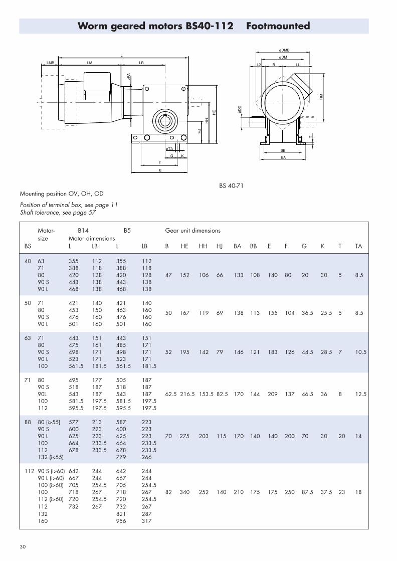
Motor- Motor dimensions Gear unit dimensionssize B14 B5
BS L LB L LB A BC øDA HA HB HC HD HE HH HJ LA LC øR
40 63 355 112 355 11271 388 118 388 11880 420 128 420 128 40 73 58 10 36 140 130 100 40 8.390 S 443 138 443 13890 L 468 138 468 138
50 71 421 140 421 14080 453 150 463 160 90 S 476 160 476 160
50 78 68 10 38 155 145 124 52 8.3
90 L 501 160 501 160
63 71 443 151 443 15180 475 161 485 17190 S 498 171 498 171 63 82 80 10 43 183 173 146 63 10.390 L 523 171 523 171100 561.5 181.5 561.5 181.5
71 80 495 177 505 18790 S 518 187 518 18790L 543 187 543 187 71 101.4 92 14 49 209 195 165 68.5 12.3100 581.5 197.5 581.5 197.5112 595.5 197.5 595.5 197.5
88 80 (i>55) 577 213 587 22390 S 600 223 600 22390 L 625 223 625 223 88 275 203 115100 664 233.5 664 233.5112 678 233.5 678 233.5132 (i<55) 779 266
112 90 S (i>60) 642 244 642 24490 L (i>60) 667 244 667 244100 (i>60) 705 254.5 705 254.5100 718 267 718 267 112 340 252 140112 (i>60) 720 254.5 720 254.5112 732 267 732 267 132 821 287 160 956 317
BS 40-71Mounting position O, hollow shaft
Position of terminal box, see page 11Shaft tolerance, see page 57
LMB� LM� LB�
L�
øPA�
HA�
HB�
A�
HD�
HC�
LC�
LA�
LC�
R(4)�
LD� BC�
LE�
øD2�
øDA�
HM�
øDMB�
øDM�
LU�
Worm geared motors BS40-112 Shaftmounted

29
Shaft- Fan Motor dimensions Withdimensions brake motor
BA BB BG E F G K T øTA øD2 LE DL FD FL DM HM LM LU PA-B14 PA-B5 DMB LMB
120 125 183 92 90 140140 140 210 102 105 160 185 73
20 92 158 152 232 113 120 200 201 72178 161 245 122 140 200 220 75178 161 270 122 140 200 220 75
140 150 210 102 105 160 185 7325 98 158 162 232 113 120 200 201 72
178 172 245 122 140 200 220 75178 172 270 122 140 200 220 75
140 163 210 102 105 160 185 73158 175 232 113 120 200 201 72
30 101 178 184 245 122 140 200 220 75178 184 270 122 140 200 220 75198 204 298 136 160 250 255 106
158 183 232 113 120 200 201 72178 192 245 122 140 200 220 75
35 122 178 192 270 122 140 200 220 75198 212 298 136 160 250 255 106221 231 312 155 160 250 278 109
158 200 232 113 120 200 201 72178 209 245 122 140 200 220 75
170 140 8 200 140 70 30 20 14 45 154 45 140 55 178 209 270 122 140 200 220 75198 229 298 136 160 250 255 106221 248 312 155 160 250 278 109248 255 381 165 300 317 135
178 233 245 122 140 200 220 75178 233 270 122 140 200 220 75198 253 298 136 160 250 255 106
210 175 18 250 175 87.5 37.5 23 18 55 174 50 140 55 198 253 298 136 160 250 255 106221 272 312 155 160 250 278 109221 272 312 155 160 250 278 109248 279 381 165 300 317 135310 332 486 210 350 375 170
BS 88-112Mounting position O, hollow shaft
Position of terminal box, see page 11Shaft tolerance, see page 57
øTA
LMB LM LB
L
FL
G K
F
E
øP
A
øF
D
A
HH
HE
HJ
LU
BA
LE
BB
DL DL
T
øD
2
BG
øDM øDMB
30
Motor- B14 B5 Gear unit dimensionssize Motor dimensions
BS L LB L LB B HE HH HJ BA BB E F G K T TA
40 63 355 112 355 11271 388 118 388 11880 420 128 420 128 47 152 106 66 133 108 140 80 20 30 5 8.590 S 443 138 443 13890 L 468 138 468 138
50 71 421 140 421 14080 453 150 463 160 90 S 476 160 476 160
50 167 119 69 138 113 155 104 36.5 25.5 5 8.5
90 L 501 160 501 160
63 71 443 151 443 15180 475 161 485 17190 S 498 171 498 171 52 195 142 79 146 121 183 126 44.5 28.5 7 10.590 L 523 171 523 171100 561.5 181.5 561.5 181.5
71 80 495 177 505 18790 S 518 187 518 18790L 543 187 543 187 62.5 216.5 153.5 82.5 170 144 209 137 46.5 36 8 12.5100 581.5 197.5 581.5 197.5112 595.5 197.5 595.5 197.5
88 80 (i>55) 577 213 587 22390 S 600 223 600 22390 L 625 223 625 223 70 275 203 115 170 140 140 200 70 30 20 14100 664 233.5 664 233.5112 678 233.5 678 233.5132 (i<55) 779 266
112 90 S (i>60) 642 244 642 24490 L (i>60) 667 244 667 244100 (i>60) 705 254.5 705 254.5100 718 267 718 267 82 340 252 140 210 175 175 250 87.5 37.5 23 18112 (i>60) 720 254.5 720 254.5112 732 267 732 267 132 821 287 160 956 317
BS 40-71Mounting position OV, OH, OD
Position of terminal box, see page 11Shaft tolerance, see page 57
F�
E�
G� K�
øTA�
HJ�
HH�
HE�
LB�
øPA�
L�
LM�LMB�
øDMB�
øDM�
LU�B�L2�
HM�
øD2�
BB�
BA�
T�
Worm geared motors BS40-112 Footmounted

31
Shaft- Fan Motor Withdimensions dimensions brake motorD2 L2 FD FL DM HM LM LU PA-B14 PA-B5 DMB LMB
120 125 183 85 90 140140 140 210 100 105 160 185 73
20 36 158 152 232 112 120 200 201 72178 161 245 121 140 200 220 75178 161 270 121 140 200 220 75
140 135 210 100 105 160 185 7325 42 158 150 232 112 120 200 201 72
178 171 245 121 140 200 220 75178 171 270 121 140 200 220 75
140 163 210 100 105 160 185 73158 175 232 112 120 200 201 72
30 58 178 184 245 121 140 200 220 75178 184 270 121 140 200 220 75198 204 298 141 160 250 255 106
158 183 232 112 120 200 201 72178 192 245 121 140 200 220 75
35 58 178 192 270 121 140 200 220 75198 212 298 141 160 250 255 106221 231 312 160 160 250 278 109
158 232 112 120 200 201 72178 245 121 140 200 220 75
45 82 140 55 178 270 121 140 200 220 75198 298 136 160 250 255 106221 312 156 160 250 278 109248 381 167 300 317 135
178 245 121 140 200 220 75178 270 121 140 200 220 75198 298 136 160 250 255 106
55 82 140 55 198 298 136 160 250 255 106221 312 156 160 250 278 109221 312 156 160 250 278 109248 381 167 300 317 135310 486 210 350 375 170
BS 88-112Mounting position OV, OH, OD
Position of terminal box, see page 11Shaft tolerance, see page 57
LMB LM LB
L
øP
A
øF
DH
J
HH
HE
FL
øTA
G K
F
E
øD
2
L2 B LU
øDMøDM
B
T
BB
BA
Series BS Eng2.:Series BS Eng. 29/8/07 13:15 Page 33

32
Motor- Motor dimensions Gear unit dimensionssize B14 B5
BS L LB L LB B HE HF HG BA BB E F G K T TA
40 63 355 112 355 11271 388 117 388 11880 420 128 420 128 47 152 98 58 133 108 140 80 20 30 5 8.590 S 443 138 443 13890 L 468 138 468 138
50 71 421 140 421 14080 453 150 463 160 90 S 476 160 476 160
50 167 110 60 138 113 155 104 36.5 25.5 5 8.5
90 L 501 160 501 160
63 71 443 151 443 15180 475 161 485 17190 S 498 171 498 171 52 195 128 65 146 121 183 126 44.5 28.5 7 10.590 L 523 171 523 171100 561.5 181.5 561.5 181.5
71 80 495 177 505 18790 S 518 187 518 18790L 543 187 543 187 62.5 216.5 141.5 70.5 169.4 143.4 209 137 46.5 36 8 12.5100 581.5 197.5 581.5 197.5112 595.5 197.5 595.5 197.5
88 80 (i>55) 577 213 587 22390 S 600 223 600 22390 L 625 223 625 223 70 275 160 72 170 140 140 200 70 30 20 14100 664 233.5 664 233.5112 678 233.5 678 233.5132 (i<55) 779 266
112 90 S (i>60) 642 244 642 24490 L (i>60) 667 244 667 244100 (i>60) 705 254.5 705 254.5100 718 267 718 267 82 340 200 88 210 175 175 250 87.5 37.5 23 18112 (i>60) 720 254.5 720 254.5112 732 267 732 267 132 821 287 160 956 317
BS 40-71Mounting position UV, UH, UD
Position of terminal box, see page 11Shaft tolerance, see page 57
HE�
øTA�
K� G�
F�
E�
HG�
HF�
LB�
L�
øPA�
LM�LMB�
øD2�
L2� B� LU�
HM�
T�
BB�
øDM�
BA�
øDMB�
Worm geared motors BS40-112 Footmounted

33
Shaft- Fan Motor Withdimensions dimensions brake motorD2 L2 FD FL DM HM LM LU PA-B14 PA-B5 DMB LMB
120 45 183 85 90 140140 60 210 100 105 160 185 73
20 36 158 72 232 112 120 200 201 72178 81 245 121 140 200 220 75178 81 270 121 140 200 220 75
140 50 210 100 105 160 185 7325 42 158 62 232 112 120 200 201 72
178 71 245 121 140 200 220 75178 71 270 121 140 200 220 75
140 37 210 100 105 160 185 73158 49 232 112 120 200 201 72
30 58 178 58 245 121 140 200 220 75178 58 270 121 140 200 220 75198 78 298 141 160 250 255 106
158 41 232 112 120 200 201 72178 50 245 121 140 200 220 75
35 58 178 50 270 121 140 200 220 75198 70 298 141 160 250 255 106221 89 312 160 160 250 278 109
158 232 112 120 200 201 72178 245 121 140 200 220 75
45 82 140 55 178 270 121 140 200 220 75198 298 136 160 250 255 106221 312 156 160 250 278 109248 381 167 300 317 135
178 245 121 140 200 220 75178 270 121 140 200 220 75198 298 136 160 250 255 106
55 82 140 55 198 298 136 160 250 255 106221 312 156 160 250 278 109221 312 156 160 250 278 109248 381 167 300 317 135310 486 210 350 375 170
BS 88-112Mounting position UV, UH, UD
Position of terminal box, see page 11Shaft tolerance, see page 57
LMB LM LB
øP
A
øF
D
HG
HF
HE
FL
G K
øTA
E
F
L
LU
T
BB
BA
øDM
øDMB
L2 B
øD
2
Series BS Eng2.:Series BS Eng. 29/8/07 13:18 Page 35

34
Motor- Motor dimensions Gear unit dimensionssize B14 B5
BS L LB L LB A HS BJ M N P øSA TE TD BH
40 63 355 112 355 11271 388 117 388 118 100 80 11880 420 128 420 128 40 46 28 1151) 951) 1401) 9 10 3 91.590 S 443 138 443 138 130 110 16090 L 463 138 468 138 165 130 200
50 71 421 140 421 140 100 80 11880 453 150 463 160 115 95 14090 S 476 160 476 160
50 48 281301) 1101) 1601) 9 10 3.5 99
90 L 501 160 501 160 165 130 200
63 71 443 151 443 15180 475 161 485 171 130 110 16090 S 498 171 498 171 63 53 35 1651) 1301) 2001) 11 12 3.5 10690 L 523 171 523 171100 561.5 181.5 561.5 181.5
71 80 495 177 505 18790 S 518 187 518 18790L 543 187 543 187 71 63 32 165 130 200 11 12 3.5 122.4100 581.5 197.5 581.5 197.5112 595.5 197.5 595.5 197.5
88 80 (i>55) 577 213 587 22390 S 600 223 600 22390 L 625 223 625 223 88 72 24 215 180 250 14 15 4 105100 664 233.5 664 233.5112 678 233.5 678 233.5132 (i<55) 779 266
112 90 S (i>60) 642 244 642 24490 L (i>60) 667 244 667 244100 (i>60) 705 254.5 705 254.5100 718 267 718 267 112 88 32 265 230 300 14 15 4 125112 (i>60) 720 254.5 720 254.5112 732 267 732 267 132 821 287 160 956 317
BS 40-71Mounting position OH
Position of terminal box, see page 11Shaft tolerance, see page 57
Worm geared motors BS40-112 Flangemounted
Standard execution, others on request.

35
Shaft- Fan Motor Withdimensions dimensions brake motorD2 L2 FD FL DM HM LM LU PA-B14 PA-B5 DMB LMB
120 125 183 85 90 140140 140 210 100 105 160 185 73
20 36 158 152 232 112 120 200 201 72178 161 245 121 140 200 220 75178 161 270 121 140 200 220 75
140 150 210 100 105 160 185 7325 42 158 162 232 112 120 200 201 72
178 171 245 121 140 200 220 75178 171 270 121 140 200 220 75
140 163 210 100 105 160 185 73158 175 232 112 120 200 201 72
30 58 178 184 245 121 140 200 220 75178 184 270 121 140 200 220 75198 204 298 141 160 250 255 106
158 183 232 112 120 200 201 72178 192 245 121 140 200 220 75
35 58 178 192 270 121 140 200 220 75198 212 298 141 160 250 255 106221 231 312 160 160 250 278 109
158 232 112 120 200 201 72178 245 121 140 200 220 75
45 82 140 55 178 270 121 140 200 220 75198 298 136 160 250 255 106221 312 156 160 250 278 109248 381 167 300 317 135
178 245 121 140 200 220 75178 270 121 140 200 220 75198 298 136 160 250 255 106
55 82 140 55 198 298 136 160 250 255 106221 312 156 160 250 278 109221 312 156 160 250 278 109248 381 167 300 317 135310 486 210 300 375 170
BS 88-112Mounting position OH
Position of terminal box, see page 11Shaft tolerance, see page 57
øF
D
LMB LM LB
L
øP
A
FL
øSA øM
HS
A
BJ
TE
TD
øD
2
øN øP
L2BHBK
LU
øDM øDMB
Series BS Eng2.:Series BS Eng. 29/8/07 13:19 Page 37

36
Motor- Motor dimensions Gear unit dimensionssize B14 B5
BS L LK LB L LK LB A BC DA HA HB HC HD HE HH HJ LA LC LN R
50/40 63 355 280 112 355 280 11271 387 295 118 388 295 118 50 78 68 10 38 155 145 124 52 124 8.380 420 307 128 420 307 128
63/40 63 355 302 112 355 302 11271 387 317 118 388 317 118 63 82 80 10 43 183 173 146 63 135 8.380 420 329 128 420 329 128
71/40 63 355 310 112 355 310 11271 387 325 118 388 325 118 71 101.4 92 14 49 209 195 165 68.5 139 10.380 420 337 128 420 337 128
88/50 71 435 412 140 435 412 14080 467 424 150 477 424 160 88 275 203 115 180 12.390 S 490 433 160 490 433 16090 L 515 433 160 515 433 160
112/63 71 466 453 151 466 453 15180 498 465 161 508 465 171 112 340 252 140 20090 S 521 474 171 521 474 17190 L 546 474 171 546 474 171100 585 494 181.5 585 494 181.5
BS 50/40 - 71/40Mounting position O, U -P7 Mountingsposition O -P7
Position of terminal box, see page 11Shaft tolerance, see page 57
R(4)�
LC� LC�
LA�HD�
A�
LU� LN�
LK�
HB�
HA�
HM�
HC�
øDA�
øD2�
BC�
LE�
LB�L�
LM�
øDM�
LD�
øPA�
Worm geared motors BS 50/40 - BS112/63 Shaftmounted

37
Shaft- Motor-dimensions dimensions
BA BB E F G K T TA D2 L2 DM HM LM LU PA
120 95 183 85 90138 113 155 104 36.5 25.5 4 8.5 25 42 140 110 210 100 105
158 122 232 112 120
120 108 183 85 90146 121 183 126 44.5 28.5 5 11 30 58 140 123 210 100 105
158 135 232 112 120
120 116 183 85 90170 144 209 137 46.5 36 6 12.5 35 58 140 131 210 100 105
158 143 232 112 120
140 138 210 100 105
170 140 200 140 70 30 20 14 45 82 158 150 232 112 120178 159 245 121 140178 159 270 121 140
140 149 210 100 105158 161 232 112 120
210 175 250 175 87.5 37.5 23 18 55 82 178 170 245 121 140178 170 270 121 140198 190 298 141 160
BS 88/50 - 112/63
Position of terminal box, see page 11Shaft tolerance, see page 57
LK
LU LN
HM
AH
J
HH
HE
G
øTA
K
F
E
L2 B LB
L
LM
øD
M
T
BB
BA
øD
2
Series BS Eng2.:Series BS Eng. 29/8/07 13:19 Page 39

38
Motor- Motor dimensions Gear unit dimensionssize B14 B5
BS L LK LB L LK LB A B HE HH HJ LN
50/40 63 387 280 112 387 280 11271 420 295 118 420 295 118 50 50 167 119 69 12480 452 307 128 452 307 128
63/40 63 405 302 112 405 302 11271 438 317 118 438 317 118 63 52 195 142 79 13580 470 329 128 470 329 128
71/40 63 415.5 310 112 415.5 310 11271 448.5 325 118 448.5 325 118 71 62.5 216.5 153.5 82.5 13980 480.5 337 128 480.5 337 128
88/50 71 502 412 140 502 412 14080 536 424 150 536 424 160 88 70 275 203 115 18090 S 557 433 160 557 433 16090 L 582 433 160 582 433 160
112/63 71 525 453 151 525 453 15180 557 465 161 557 465 171 112 82 340 252 140 20090 S 580 474 171 580 474 17190 L 605 474 171 605 474 171100 643.5 494 181.5 643.5 494 181.5
BS 50/40 - 71/40Mounting position OV, OH, OO - P7 Mounting position OV - P7
Position of terminal box, see page 11Shaft tolerance, see page 57
LK�
LU� LN�
HM�
A�
HJ�
HH�
HE�
øTA�
G� K�
F�
E�
BB�
BA�
øD2�
L2� B� LB�
L�
LM�
øDM�
T�
øPA�
OV� OH�
Worm geared motors BS50/40 - BS 112/63 Footmounted

39
Shaft- Motor-dimensions dimensions
BA BB BG E F G K T TA D2 LE DL DM HM LM LU PA
120 95 183 85 9025 98 140 110 210 100 105
158 122 232 112 120
120 108 183 85 9030 101 140 123 210 100 105
158 135 232 112 120
120 116 183 85 9035 122 140 131 210 100 105
158 143 232 112 120
140 138 210 100 105
170 140 8 200 140 70 30 20 14 45 154 45 158 150 232 112 120178 159 245 121 140178 159 270 121 140
140 149 210 100 105158 161 232 112 120
210 175 18 250 175 87.5 37.5 23 18 55 174 50 178 170 245 121 140178 170 270 121 140198 190 298 141 160
BS 88/50 - 112/63Mounting position 0,O - P7
Position of terminal box, see page 11Shaft tolerance, see page 57
HM
LU LN
LK
HH
HE
HJ
øTA
G K
F
E
LB LM
L
øD
M
BB
DLDL
LE
BA
BG
øD
2
Series BS Eng2.:Series BS Eng. 29/8/07 13:20 Page 41

40
Ratio Input Output Input Output Efficiency Thermal rating 1) Overhungand code speed speed power torque load
Shaft- Foot-n1 n2 P1 T2 η mount mount Fr2
i rpm rpm kW Nm % kW kW N
10 A 2860 286 .80 19 71 .47 .63 13001430 143 .49 26 79 .47 .60 1700930 93 .37 31 81 .37 .50 1900700 70 .31 35 81 .33 .42 2000
15 B 2860 191 .58 19 65 .36 .47 16001430 95 .35 26 74 .34 .44 2000930 62 .27 31 74 .28 .36 2000700 47 .22 35 76 .24 .31 2000
20 C 2860 143 .51 19 55 .25 .34 18001430 72 .30 26 64 .26 .33 2000930 46 .22 31 67 .21 .27 2000700 35 .18 34 69 .18 .24 2000
25 D 2860 114 .46 19 49 .22 .29 19001430 57 .26 26 60 .22 .28 2000930 37 .19 31 62 .18 .24 2000700 28 .16 35 64 .16 .20 2000
30 E 2860 95 .38 19 49 .21 .29 20001430 48 .22 26 60 .21 .26 2000930 31 .17 31 59 .17 .22 2000700 23 .14 36 61 .15 .19 2000
40 F 2860 72 .37 19 38 .16 .23 20001430 36 .20 26 48 .16 .20 2000930 23 .15 31 51 .13 .17 2000700 18 .12 35 53 .12 .15 2000
50 G 2860 57 .34 19 33 .15 .20 20001430 29 .18 26 42 .14 .18 2000930 19 .13 31 45 .12 .15 2000700 14 .11 35 48 .10 .13 2000
BS 35 Power ratings
1) Gearbox with fan or motor motor with fan,flange mounted on the gearbox.

Ratio Input Output Input Output Efficiency Thermal rating 1) Overhungand code speed speed power torque load
Shaft- Foot-n1 n2 P1 T2 η mount mount Fr2
i rpm rpm kW Nm % kW kW N
2860 429 1.9 37 85 .89 1.2 13006.67 1430 214 1.3 50 86 1.1 1.3 1700
(20/3) 930 139 .99 59 87 .84 1.0 1900A 730 109 .87 66 86 .73 .92 2000
2860 286 1.5 43 83 .86 1.1 160010 1430 143 1.0 57 85 1.0 1.2 2000
(20/2) 930 93 .78 69 85 .79 .99 2000B 730 73 .68 76 85 .69 .86 2000
2860 191 1.1 44 78 .65 .87 190015 1430 95 .73 58 79 .75 .92 2000
(30/2) 930 62 .56 70 80 .58 .73 2000C 730 49 .50 77 79 .51 .64 2000
2860 143 .91 44 72 .53 .70 200020 1430 72 .58 58 75 .60 .73 2000
(20/1) 930 46 .45 70 75 .47 .58 2000D 730 36 .40 78 74 .41 .52 2000
2860 119 .80 44 69 .47 .62 200024 1430 60 .51 58 71 .53 .65 2000
(24/1) 930 39 .39 70 72 .41 .51 2000730 30 .35 78 71 .36 .45 2000
2860 95 .69 44 64 .41 .53 200030 1430 48 .44 59 67 .45 .54 2000
(30/1) 930 31 .34 70 67 .35 .44 2000F 730 24 .30 78 66 .31 .39 2000
2860 72 .57 43 56 .34 .44 200040 1430 36 .37 58 59 .36 .44 2000
(40/1) 930 23 .28 69 60 .28 .35 2000G 730 18 .25 76 58 .25 .31 2000
2860 60 .52 44 52 .32 .41 200048 1430 30 .32 58 56 .33 .40 2000
(48/1) 930 19 .24 66 56 .26 .33 2000H 730 15 .21 71 55 .23 .29 2000
2860 48 .45 42 46 .29 .37 200060 1430 24 .26 52 49 .29 .35 2000
(60/1) 930 16 .18 54 49 .23 .29 2000I 730 12 .15 56 47 .21 .26 2000
2860 41 .39 40 43 .29 .36 200070 1430 20 .21 44 44 .29 .35 2000
(70/1) 930 13 .14 46 46 .23 .28 2000J 730 10 .11 47 44 .20 .25 2000
2860 34 .32 31 34 .27 .33 200084 1430 17 .16 33 36 .27 .32 2000
(84/1) 930 11 .10 35 38 .21 .26 2000K 730 8.7 .09 36 37 .19 .23 2000
41
BS 40 Power ratings
1) Gearbox with fan or motor motor with fan,flange mounted on the gearbox.

Ratio Input Output Input Output Efficiency Thermal rating 1) Overhungand code speed speed power torque load
Shaft- Foot-n1 n2 P1 T2 η mount mount Fr2
i rpm rpm kW Nm % kW kW N
8 2860 358 2.6 62 88 1.7 2.2 1900(24/3) 1430 179 1.7 83 88 1.7 2.1 2400
A 930 116 1.4 99 88 1.3 1.6 2700730 91 1.2 110 88 1.1 1.4 2700
10.5 2860 272 2.1 65 86 1.4 1.8 2200(21/2) 1430 136 1.4 87 87 1.4 1.7 2700
B 930 89 1.1 103 85 1.1 1.4 2700 730 70 .97 114 85 .94 1 .2 2700
14 2860 204 1.7 66 82 1.2 1.5 2500(28/2) 1430 102 1.1 88 84 1.2 1.5 2700
C 930 66 .88 105 83 .91 1.1 2700730 52 .77 117 83 .78 .97 2700
21 2860 136 1.2 66 76 .86 1.1 2700(21/1) 1430 68 .80 87 77 .84 1.0 2700
D 930 44 .63 104 76 .64 .80 2700730 35 .56 116 75 .56 .69 2700
24 2860 119 1.1 63 73 .74 .93 2700(24/1) 1430 60 .71 85 74 .72 .87 2700
E 930 39 .57 102 72 .55 .69 2700730 30 .49 112 72 .48 .60 2700
32 2860 89 .92 68 69 .69 .86 2700(32/1) 1430 45 .59 90 71 .65 .79 2700
F 930 29 .47 108 69 .50 .62 2700730 23 .41 120 69 .43 .54 2700
37 2860 77 .82 66 65 .59 .73 2700(37/1) 1430 39 .53 88 66 .56 .67 2700
Fx 930 25 .43 106 64 .43 .53 2700730 20 .37 116 64 .37 .47 2700
42 2860 68 .76 68 63 .57 .70 2700 (42/1) 1430 34 .49 90 65 .54 .65 2700
G 930 22 .40 109 63 .42 .51 2700730 17 .34 120 63 .36 .45 2700
54 2860 53 .66 68 57 .49 .61 2700(54/1) 1430 26 .42 90 59 .46 .55 2700
H 930 17 .34 109 57 .35 .43 2700730 14 .30 120 57 .31 .38 2700
64 2860 45 .60 69 53 .46 .56 2700(64/1) 1430 22 .39 93 55 .42 .51 2700
I 930 15 .28 100 53 .33 .40 2700730 11 .23 102 53 .29 .36 2700
80 2860 36 .50 66 49 .44 .53 2700(80/1) 1430 18 .27 71 49 .40 .47 2700
J 930 12 .19 75 47 .31 .38 2700730 9.1 .15 77 47 .27 .34 2700
42
BS 50 Power ratings
1) Gearbox with fan or motor motor with fan,flange mounted on the gearbox.

Ratio Input Output Input Output Efficiency Thermal rating 1) Overhungand code speed speed power torque load
Shaft- Foot-n1 n2 P1 T2 η mount mount Fr2
i rpm rpm kW Nm % kW kW N
7.75 2860 369 4.3 101 91 2.8 3.5 2100(31/4) 1430 185 2.9 134 90 2.6 3.2 2600
A 930 120 2.3 162 90 2.0 2.4 2900730 94 2.0 178 89 1.7 2.1 3200
11 2860 260 3.4 112 89 2.6 3.2 2400(33/3) 1430 130 2.3 149 88 2.3 2.8 3000
B 930 85 1.8 178 88 1.7 2.1 3400730 66 1.6 197 88 1.5 1.8 3700
14 2860 204 2.8 115 87 2.2 2.7 2700(28/2) 1430 102 1.9 154 87 2.0 2.4 3400
C 930 66 1.3 160 86 1.5 1.8 4000730 52 1.0 160 85 1.2 1.6 4000
18 2860 159 2.2 111 82 1.7 2.1 3100(36/2) 1430 79 1.5 149 83 1.5 1.8 3900
D 930 52 1.2 178 83 1.1 1.4 4000730 41 1.0 196 81 .97 1.2 4000
24.5 2860 117 1.8 119 80 1.5 1.9 3500(49/2) 1430 58 1.2 160 81 1.4 1.6 4000
E 930 38 .81 162 79 1.0 1.3 4000730 30 .64 162 79 .87 1.1 4000
29 2860 99 1.6 117 77 1.3 1.6 3800(29/1) 1430 49 1.0 156 77 1.1 1.4 4000
F 930 32 .82 188 77 .86 1.1 4000730 25 .67 192 75 .74 .92 4000
37 2860 77 1.3 109 69 .92 1.1 4000(37/1) 1430 39 .85 147 70 .81 .97 4000
Fx 930 25 .67 175 68 .62 .77 4000730 20 .60 194 67 .54 .67 4000
43 2860 67 1.2 121 70 1.0 1.2 4000(43/1) 1430 33 .78 160 71 .89 1.1 4000
G 930 22 .53 166 70 .67 .82 4000730 17 .43 165 68 .57 .71 4000
51 2860 56 1.1 121 67 .89 1.1 4000(51/1) 1430 28 .69 160 67 .78 .93 4000
H 930 18 .53 184 66 .59 .73 4000730 14 .42 183 65 .51 .63 4000
57 2860 50 .98 121 64 .83 1.0 4000(57/1) 1430 25 .64 160 65 .73 .87 4000
I 930 16 .51 193 64 .55 .68 4000730 13 .41 193 62 .47 .59 4000
73 2860 39 .85 121 58 .72 .87 4000(73/1) 1430 20 .56 162 59 .61 .74 4000
J 930 13 .40 174 58 .47 .57 4000730 10 .33 179 56 .41 .51 4000
104 2860 28 .56 92 47 .61 .73 4000(104/1) 1430 14 .31 100 46 .52 .62 4000
K 930 8.9 .21 105 47 .40 .49 4000730 7 .17 107 45 .35 .43 4000
43
BS 63 Power ratings
1) Gearbox with fan or motor motor with fan,flange mounted on the gearbox.

Ratio Input Output Input Output Efficiency Thermal rating 1) Overhungand code speed speed power torque load
Shaft- Foot-n1 n2 P1 T2 η mount mount Fr2
i rpm rpm kW Nm % kW kW N
7.5 2860 381 6.5 151 92 3.2 4.4 2200(30/4) 1430 191 4.3 201 92 3.6 3.8 2700
A 930 124 3.4 242 91 2.4 2.9 3100 730 97 3.0 267 91 2.0 2.5 3300
9.33 2860 307 5.7 163 91 3.4 4.2 2400 (28/3) 1430 153 3.8 218 91 3.1 3.7 3000
B 930 100 3.0 260 90 2.3 2.8 3400 730 78 2.6 288 89 1.9 2.4 3600
12 2860 238 4.5 160 89 2.7 3.3 2900(36/3) 1430 119 3.0 215 88 2.4 2.9 3500
C 930 78 2.3 255 88 1.8 2.2 4000730 61 2.0 282 87 1.5 1.9 4300
16 2860 179 3.6 169 87 2.3 2.8 3300(32/2) 1430 89 2.4 224 87 2.0 2.5 4000
D 930 58 1.9 269 85 1.5 1.9 4600 730 46 1.7 297 85 1.3 1.6 5000
21 2860 136 2.9 173 84 2.0 2.4 3700(42/2) 1430 68 1.9 230 84 1.7 2.0 4600
E 930 44 1.5 276 83 1.3 1.6 5000730 35 1.4 305 82 1.1 1.4 5000
28 2860 102 2.2 168 80 1.5 1 .8 4200(28/1) 1430 51 1.5 225 79 1.3 1.5 5000
F 930 33 1.2 267 77 .97 1.2 5000730 26 1.0 298 77 .83 1.0 5000
37 2860 77 1.9 178 76 1.3 1.6 4700(37/1) 1430 39 1.3 238 76 1.1 1.3 5000
G 930 25 1.0 283 74 .84 1.0 5000 730 20 .89 315 73 .72 .89 5000
48 2860 60 1.5 175 71 1.1 1.3 5000(48/1) 1430 30 1.0 234 71 .93 1.1 5000
H 930 19 .82 281 69 .70 .86 5000730 15 .72 310 68 .60 .75 5000
63 2860 45 1.3 175 66 .89 1.1 5000(63/1) 1430 23 .85 234 65 .76 .91 5000
I 930 15 .69 281 63 .58 .71 5000730 12 .61 310 61 .51 .63 5000
82 2860 35 1.1 178 60 .77 .92 5000(82/1) 1430 17 .62 201 58 .66 .79 5000
J 930 11 .45 211 56 .50 .61 5000730 8.9 .37 216 54 .44 .54 5000
100 2860 29 .77 143 56 .76 .91 5000(100/1) 1430 14 .42 154 54 .64 .77 5000
K 930 9.3 .30 162 49 .49 .60 5000730 7.3 .25 166 43 .43 .53 5000
44
BS 71 Power ratings
1) Gearbox with fan or motor motor with fan,flange mounted on the gearbox.

Ratio Input Output Input Output Efficiency Thermal rating 1) Overhungand code speed speed power torque load
Shaft- Foot-n1 n2 P1 T2 η mount mount Fr2
i rpm rpm kW Nm % kW kW N
2860 394 15.6 358 94 9.3 11 .3 40007.25 1430 197 9.9 449 94 6.7 8.4 5000
(29/4) 930 128 7.5 518 93 4.5 5.9 5800A 730 101 6.4 560 92 3.6 4.9 6300
2860 243 10.1 368 93 7.6 9.3 510011.75 1430 122 6.8 490 91 5.4 6.8 6300(47/4) 930 79 5.1 564 90 3.6 4.8 7300
B 730 62 4.4 611 90 2.9 4.0 7900
2860 183 7.7 364 90 6.1 7.4 600015.67 1430 91 5.1 481 89 4.3 5.4 7400 (47/3) 930 59 3.9 562 88 2.9 3.8 8500
C 730 47 3.4 610 87 2.3 3.2 9200
2860 147 6.6 377 88 4.7 5.7 660019.5 1430 73 4.4 496 87 3.3 4.2 8200
(39/2) 930 48 3.4 578 85 2.3 3.0 9400D 730 37 2.9 627 84 1.8 2.5 10000
2860 122 5.4 367 86 4.4 5.3 720023.5 1430 61 3.6 479 85 3.1 3.9 9000
(47/2) 930 40 2.7 556 84 2.1 2.7 10000E 730 31 2.3 602 83 1.7 2.3 10000
2860 99 5.2 413 82 3.0 3.7 880029 1430 49 3.3 524 80 2.2 2.7 10000
(29/1) 930 32 2.6 604 78 1.5 2.0 10000F 730 25 2.2 654 77 1.2 1.7 10000
2860 73 3.9 406 79 2.7 3.2 960039 1430 37 2.6 525 77 1.9 2.4 10000
(39/1) 930 24 2.0 606 74 1.3 1.7 10000G 730 19 1.7 654 73 1.1 1.5 10000
2860 61 3.2 396 77 2.5 3.0 1000047 1430 30 2 1 508 75 1.8 2.2 10000
(47/1) 930 20 1.7 585 73 1.2 1.6 10000H 730 16 1.4 630 72 .99 1.3 10000
2860 49 2.7 383 74 2.3 2.8 1000058 1430 25 1.7 488 72 1.7 2.1 10000
(58/1) 930 16 1.3 560 69 1.1 1.5 10000J 730 13 1.2 602 68 .92 1.2 10000
2860 40 2.1 343 69 1.9 2.3 1000071 1430 20 1.4 437 67 1.4 1.7 10000
(71/1) 930 13 1.1 492 64 .95 1.2 10000K 730 10 .86 505 63 .78 1.0 10000
2860 35 1.8 341 68 1.9 2.3 1000082 1430 17 1.1 390 66 1.4 1.7 10000
(82/1) 930 11 .77 409 62 .94 1.2 10000L 730 8.9 .64 420 61 .77 1.0 10000
2860 27 1.2 248 59 1.6 2.0 10000106 1430 13 .66 269 57 1.2 1.5 10000
(106/1) 930 8.8 .47 281 55 .81 1.1 10000M 730 6.9 .39 289 54 .67 .90 10000
45
BS 88 Power ratings
1) Gearbox with fan or motor motor with fan,flange mounted on the gearbox.

Ratio Input Output Input Output Efficiency Thermal rating 1) Overhungand code speed speed power torque load
Shaft- Foot-n1 n2 P1 T2 η mount mount Fr2
i rpm rpm kW Nm % kW kW N
7 2860 409 27.3 607 95 20.0 24.1 6200(28/4) 1430 204 18.3 806 94 13.9 17.2 7600
A 930 133 13.8 929 93 9.3 12.2 8900730 104 11.7 1006 93 7.4 10.0 9500
11.5 2860 249 19.7 709 93 17.5 21.0 7500(46/4) 1430 124 12.5 891 93 11.8 14.6 9500
B 930 81 9.4 1026 92 7.8 10.2 10900730 63 8.1 1111 91 6.2 8.4 11800
15.3 2860 187 14.9 705 92 14.0 16.8 8900(46/3) 1430 93 10.0 936 91 9.4 11.6 11000
C 930 61 7.6 1078 90 6.3 8.2 12700730 48 6.5 1167 90 5.0 6.7 13800
19.5 2860 147 11.8 691 89 10.6 12.7 10300(39/2) 1430 73 7.9 912 88 7.2 9.0 12800
D 930 48 6.0 1064 87 4.8 6.3 14800730 37 5.2 1155 87 3.8 5.2 15000
23 2860 124 10.3 708 89 10.0 11.9 10900(46/2) 1430 62 6.8 928 88 6.7 8.3 13600
E 930 40 5.3 1080 86 4.5 5.9 15000730 32 4.5 1171 85 3.6 4.8 15000
28 2860 102 8.6 679 84 6.5 7.7 12100(28/1) 1430 51 5.7 893 83 4.5 5.5 15000
F 930 33 4.5 1041 80 3.1 4.0 15000730 26 3.9 1129 79 2.5 3.3 15000
39 2860 73 6.9 741 82 5.9 7.1 13700(39/1 ) 1430 37 4.6 960 80 4.1 5.0 15000
G 930 24 3.5 1111 78 2.8 3.6 15000730 19 3.0 1200 77 2.2 3.0 15000
46 2860 62 6.1 755 81 5.6 6.7 14600(46/1) 1430 31 4.0 974 79 3.8 4.7 15000
H 930 20 2.1 1124 77 2.6 3.4 15000730 16 1.8 1212 75 2.1 2.8 15000
63 2860 45 4.2 684 77 4.8 5.8 15000(63/1) 1430 23 2.7 874 75 3.3 4.1 15000
J 930 15 3.1 1003 73 2.2 2.9 15000730 12 2.7 1065 71 1.8 2.4 15000
76 2860 38 3.5 654 73 4.4 5.2 15000(76/1) 1430 19 2.3 831 71 3.0 3.7 15000
K 930 12 1.6 861 69 2.0 2.6 15000730 9.6 1.3 858 68 1.6 2.2 15000
95 2860 30 2.7 587 69 3.7 4.4 15000(95/1) 1430 15 1.5 636 66 2.5 3.1 15000
L 930 9.8 1.1 667 63 1.7 2.2 15000730 7.7 .89 684 62 1.4 1.9 15000
108 2860 26 2.1 484 64 3.4 4.0 15000(108/1) 1430 13 1.2 524 61 2.3 2.9 15000
M 930 8.6 .83 549 59 1.6 1.7 15000730 6.8 .69 563 58 1.3 1.7 15000
46
BS 112 Power ratings
1) Gearbox with fan or motor motor with fan,flange mounted on the gearbox.

47
1) Gearbox with fan or motor motor with fan,flange mounted on the gearbox.
Double worm gears Power ratings
BS 71/4 0
BS 88/5 0
BS 112/63
BS 63/4 0
BS 50/40
Ratio Input Output Input Output Efficiency Thermal rating 1) Overhungand code speed speed power torque load
Shaft- Foot-n1 n2 P1 T2 η mount mount Fr2
Code i rpm rpm kW Nm % kW kW N
EA 160 1430 8.9 .31 150 45 .30 .38 2700EB 240 1430 6 .24 150 39 .27 .34 2700EC 360 1430 4 .20 150 32 .25 .31 2700ED 480 1430 3 .17 150 28 .23 .30 2700EE 576 1430 2.5 .16 150 25 .23 .29 2700EF 720 1430 2 .14 150 22 .22 .28 2700EG 960 1430 1.5 .13 150 18 .21 .27 2700EH 1152 1430 1.2 .12 150 16 .21 .27 2700El 1440 1430 1 .12 150 13 .20 .26 2700EJ 1680 1430 0.9 .12 150 12 .20 .26 2700EK 2016 1430 0.7 .11 150 10 .20 .26 2700
FA 193 1430 7.4 .40 250 48 .44 .56 4000FB 290 1430 4.9 .31 250 42 .40 .51 4000FC 435 1430 3.3 .25 250 34 .36 .46 4000FD 580 1430 2.5 .23 250 29 .35 .44 4000FE 696 1430 2.1 .21 250 26 .33 .42 4000FF 870 1430 1.6 .18 250 23 .32 .41 4000FG 1160 1430 1.2 .17 250 19 .31 .39 4000FH 1392 1430 1 .16 250 16 .30 .39 4000Fl 1740 1430 0.8 .15 250 14 .29 .35 4000FJ 2030 1430 0.7 .15 250 12 .29 .35 4000FK 2436 1430 0.6 .14 250 11 .27 .32 4000
FA 187 1430 7.7 .58 400 55 .50 .63 5000FB 280 1430 5.1 .43 400 50 .44 .56 5000FC 420 1430 3.4 .33 400 42 .40 .51 5000FD 560 1430 2.6 .28 400 38 .38 .48 5000FE 672 1430 2.1 .26 400 34 .37 .47 5000FF 840 1430 1.7 .23 400 31 .35 .45 5000FG 1120 1430 1.3 .20 400 26 .34 .43 5000FH 1344 1430 1.1 .18 400 24 .33 .40 5000Fl 1680 1430 0.9 .17 400 21 .29 .35 5000FJ 1960 1430 0.7 .16 400 19 .29 .35 5000FK 2352 1430 0.6 .15 400 17 .27 .32 5000
FA 232 1430 6.2 .92 800 56 .61 .89 10000FB 304 1430 4.7 .75 800 52 .57 .82 10000FC 406 1430 3.5 .62 800 47 .53 .77 10000FD 609 1430 2.3 .47 800 41 .48 .69 10000FE 696 1430 2.1 .45 800 38 .47 .68 10000FF 928 1430 1.5 .37 800 34 .44 .64 10000FFX 1073 1430 1.3 .35 800 32 .43 .63 10000FG 1218 1430 1.2 .32 800 30 .43 .62 10000FH 1566 1430 0.9 .29 800 26 .42 .55 10000Fl 1856 1430 0.8 .27 800 24 .41 .51 10000FJ 2320 1430 0.6 .23 800 22 .40 .47 10000
FA 217 1430 6.6 1.6 1400 61 1.2 1.7 15000FB 308 1430 4.6 1.2 1400 56 1.1 1.6 15000FC 392 1430 3.6 1.0 1400 53 1.0 1.5 15000FD 504 1430 2.8 .86 1400 48 .95 1.4 15000FE 686 1430 2.1 .68 1400 44 .89 1.3 15000FF 812 1430 1.8 .62 1400 41 .85 1.2 15000FFX 1036 1430 1.4 .56 1400 36 .81 .97 15000FG 1204 1430 1.2 .49 1400 35 .79 1.1 15000FH 1428 1430 1.0 .45 1400 32 .77 .93 15000Fl 1596 1430 0.9 .42 1400 30 .73 .87 15000FJ 2044 1430 0.7 .37 1400 27 .61 .74 15000FK 2912 1430 0.5 .31 1400 22 .52 .62 15000

48
BC�
LE�
øDA�
øD2�
SE�
MF�
A�
HB�
HD�
HC�
HA�
L�
LB�
L1�øD1�
R(4)�
LC� LC�LD��
LX�
ME�
LA�
øD1�
L1�
LB�
L�
F�
E�
G�
øTA� BB�
BA�
T�
øD2�
L2� B�
HG�
HF�
HE�
K�
Mounting position UV, UH, UD Mounting position UV
Shaft tolerance, see page 57
BS A BC D1 D2 DA HA HB HC HD L L1 LA LB LC LD LE LX ME MF øR SE Kgs
40 40 73 14 20 58 10 36 140 130 146 25 100 86 40 10 92 8.5 46 46 8.1 M8x12 3.0
50 50 78 19 25 68 10 38 155 145 179 35 124 108 52 10 98 8 56.6 56.6 8.3 M8x12 4.8
63 63 82 19 30 80 10 43 183 173 200.5 35 146 118.5 63 10 101 7 56.6 56.6 10.3 M8x12 6.5
71 71 101.4 24 35 92 14 49 209 195 214 40 165 128 68.5 14 122 7.3 76.4 76.4 12.5 M8x14 9.6
BS B BA BB D1 D2 E F G HE HF HG K L L1 L2 LB T TA Kgs
40 47 133 108 14 20 140 80 20 152 98 58 30 146 25 36 86 5 8.5 3.0
50 50 138 113 19 25 155 104 36.5 167 110 60 25.5 179 35 42 108 5 8.5 4.8
63 52 146 121 19 30 183 126 44.5 195 128 65 28.5 200.5 35 58 118.5 7 10.5 6.5
71 62.5 169.4 143.4 24 35 209 137 46.5 216.5 141.5 70.5 36 214 40 58 128 8 12.5 9.6
Standard execution BS40-71
Underdriven worm gear with feet and output shaft
Mounting position O, hollow shaft

49
F�
E�
G� K�
øTA� BB�
BA�
T�
øD2�
HH�
HE�
L1�
LB�
L�
L2� B�
HG�
øD1�
E�
F�
øTA�
GA� K�
HE�
LB�
L1�
øD1�
øD2�
L2�B�T�
BB�
BA�
HK�
Mounting position VV, VH, VD Mounting position VV
Shaft tolerance, see page 57
BS B BA BB D1 D2 E F G HE HH HG K L L1 L2 LB T TA Kgs
40 47 133 108 14 20 140 80 20 152 106 66 30 146 25 36 86 5 8.5 3.0
50 50 138 113 19 25 155 104 36.5 167 119 69 25.5 179 35 42 108 5 8.5 4.8
63 52 146 121 19 30 183 126 44.5 195 142 79 28.5 200.5 35 58 118.5 7 10.5 6.5
71 62.5 169.4 143.4 24 35 209 137 46.5 216.5 153.5 82.5 36 214 40 58 128 8 12.5 9.6
BS B BA BB D1 D2 E F GA HE HK K L1 L2 LB T TA Kgs
40 47 133 108 14 20 140 80 24 62 148 30 25 36 86 5 8.5 3.9
50 50 138 113 19 25 155 104 31.5 74 182 25.5 35 42 108 5 8.5 6.1
63 52 146 121 19 30 183 126 38.5 85 203.5 28.5 35 58 118.5 7 10.5 8.3
71 62.5 169.4 143.4 24 35 209 137 39 90 218 36 40 58 128 8 12.5 12.0
Overdriven worm gear with feet and output shaft
Worm gear with vertical worm screw, feet and output shaft
Mounting position OV, OH, OD Mounting position OV

50
TC
�
BD��
KA� GB�
BF�
BE�
X�
B�
HI�
L2�
HN
�
A�
L�
LB�
øD2�L1��
øD
1�
LF�
LE�
øTB�
Mounting position O- orU-hollow shaft
Shaft tolerance, see page 57
BS A B BD BE BF D1 D2 GB HI HN KA L L1 L2 LB LE LF TB TC X Kgs
40 40 47 40 181 162 14 20 57 131.5 48.5 9.5 146 25 36 86 100 80 9 12 49 4.1
50 50 50 40 196 177 19 25 59 143 51 9.5 179 35 42 108 124 104 9 12 52 6.4
63 63 52 45 233 213 19 30 68 163 53 10 200.5 35 58 118.5 146 126 11 12 54 8.7
71 71 62.5 55 266 241 24 35 79 186.5 66 12.5 214 40 58 128 165 137 12.5 15 64.5 12.7
Size Motor- Flangesize type A BC D2 DA HAHB HC HD L LA LB LC LD LE MA NA PA øR S TM Kgs63 B14 172 112 75 60 92 6 8 3.6
40 71 B14 40 73 20 58 10 36 140 130 178 100 118 40 10 92 85 70 102 8.3 7 9 3.680 B14 188 128 100 80 118 7 10 3.690 B14 198 138 115 95 140 9 12 3.671 B14 211 140 85 70 108 7 10 5.5
50 80 B14 50 78 25 68 10 38 155 145 221 124 150 52 10 98 100 80 118 8.3 7 10 5.790 B14 231 160 115 95 140 9 12 5.971 B14 233 151 85 70 108 7 10 7.2
63 80 B14 63 82 30 80 10 43 183 173 243 146 161 63 10 101 100 80 118 10.3 7 10 7.490 B14 253 171 115 95 140 9 12 7.6100 B14 263.5 181.5 130 110 160 9 12 7.880 B14 263 177 100 80 118 7 10 10.6
71 90 B14 71 104.5 35 92 14 49 209 195 273 165 187 68.5 14 122 115 95 140 12.3 9 12 10.8100/112 B14 283.5 197.5 130 110 160 9 12 11.0
Worm gear with horizontal input shaft and feet
Standard execution with motorflange
Mounting position HU, HN, HD. Also state position of input shaft A or B. Mounting position HU-B
øMA
øNA
øS
øD
2
DA
BC
LE
HA
HB
A
HD
HC
LCLC
LA
LD
R(4
)
øP
A
TM
LB
L
BS40 M90 45BS71 45
Series BS Eng2.:Series BS Eng. 29/8/07 14:41 Page 52
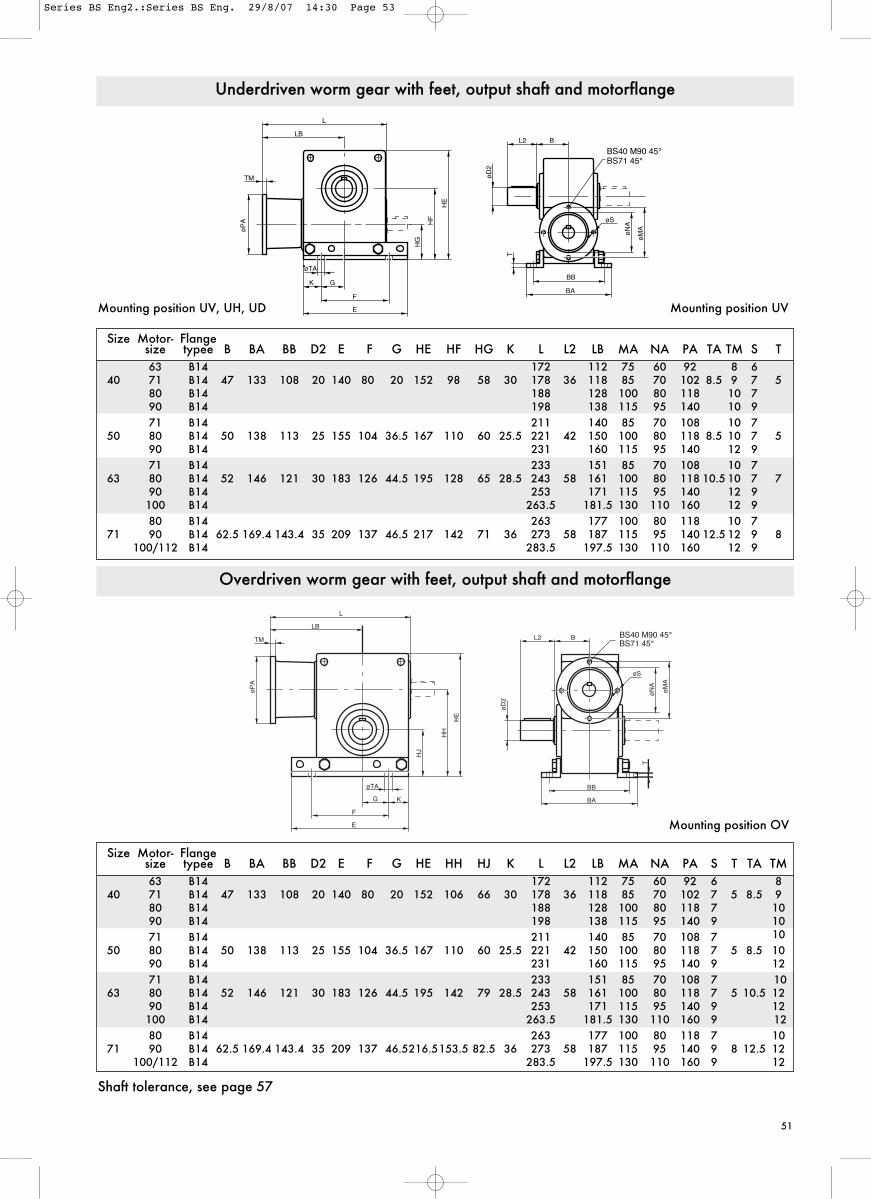
51
øP
A�
TM�
LB�
L�
HG
�
HF
�
HE
�
øTA�
K� G��
F�
E�
T�
BB�
BA�
øS�
øN
A�
øM
A�
øD
2�
L2��
B�
BS71 45°�BS40 M90 45°�
Mounting position OV
Shaft tolerance, see page 57
Size Motor- Flangesize typee B BA BB D2 E F G HE HH HJ K L L2 LB MA NA PA S T TA TM63 B14 172 112 75 60 92 6 8
40 71 B14 47 133 108 20 140 80 20 152 106 66 30 178 36 118 85 70 102 7 5 8.5 980 B14 188 128 100 80 118 7 1090 B14 198 138 115 95 140 9 1071 B14 211 140 85 70 108 7 10
50 80 B14 50 138 113 25 155 104 36.5 167 110 60 25.5 221 42 150 100 80 118 7 5 8.5 1090 B14 231 160 115 95 140 9 1271 B14 233 151 85 70 108 7 10
63 80 B14 52 146 121 30 183 126 44.5 195 142 79 28.5 243 58 161 100 80 118 7 5 10.5 1290 B14 253 171 115 95 140 9 12100 B14 263.5 181.5 130 110 160 9 1280 B14 263 177 100 80 118 7 10
71 90 B14 62.5 169.4 143.4 35 209 137 46.5216.5153.5 82.5 36 273 58 187 115 95 140 9 8 12.5 12100/112 B14 283.5 197.5 130 110 160 9 12
Size Motor- Flangesize typee B BA BB D2 E F G HE HF HG K L L2 LB MA NA PA TA TM S T63 B14 172 112 75 60 92 8 6
40 71 B14 47 133 108 20 140 80 20 152 98 58 30 178 36 118 85 70 102 8.5 9 7 580 B14 188 128 100 80 118 10 790 B14 198 138 115 95 140 10 971 B14 211 140 85 70 108 10 7
50 80 B14 50 138 113 25 155 104 36.5 167 110 60 25.5 221 42 150 100 80 118 8.5 10 7 590 B14 231 160 115 95 140 12 971 B14 233 151 85 70 108 10 7
63 80 B14 52 146 121 30 183 126 44.5 195 128 65 28.5 243 58 161 100 80 118 10.5 10 7 790 B14 253 171 115 95 140 12 9100 B14 263.5 181.5 130 110 160 12 980 B14 263 177 100 80 118 10 7
71 90 B14 62.5 169.4 143.4 35 209 137 46.5 217 142 71 36 273 58 187 115 95 140 12.5 12 9 8100/112 B14 283.5 197.5 130 110 160 12 9
Underdriven worm gear with feet, output shaft and motorflange
Overdriven worm gear with feet, output shaft and motorflange
Mounting position UV, UH, UD Mounting position UV
øP
A
TM
LB
L
F
E
G K
øTA
HJ
HH
HE
øD
2
L2 B
BB
BA
øS
øN
A
øM
A
TBS71 45°BS40 M90 45°
Series BS Eng2.:Series BS Eng. 29/8/07 14:30 Page 53

52
B�
øMA�
øNA�
øS(4x)�
L2�
BB�
BA�
T�
øTA�
GA� K�
F�
E�
øPA�
TM
�
HL�
HR
�
LB�
øD
2�
BS71 45°�
Size Motor- Flangesize type B BA BB D2 E F GA HR HL K L2 LB MA NA PA S T TA TM Vikt
40 63 B14 174 112 75 60 92 6 8 4.571 B14 47 133 108 20 140 80 24 180 62 30 36 118 85 70 102 7 5 8.5 9 4.580 B14 190 128 100 80 118 7 10 4.590 B14 200 138 115 95 140 9 10 4.571 B14 214 140 85 70 108 7 10 6.8
50 80 B14 50 138 113 25 155 104 31.5 224 74 25.542 150 100 80 118 7 5 8.5 10 7.090 B14 234 160 115 95 140 9 12 7.2 71 B14 236 151 85 70 108 10 9.0
63 80 B14 52 146 121 30 183 126 38.5 246 85 28.558 161 100 80 118 7 10.5 10 9.290 B14 256 171 115 95 140 9 7 12 9.4100 B14 266.5 181.5130 110 160 9 12 9.6
71 80 B14 267 177 100 80 118 7 10 13.090 B14 62.5 169.4 143.4 35 209 137 39 277 90 36 58 187 115 95 140 9 8 12.5 12 13.2
100/112 B14 287.5 197.5130 110 160 9 12 13.4
Worm gear with vertical worm screw, feet, output shaft and motorflange
Mounting position VV, VH, VD Mounting position VV
Size Motorsize LB MA NA PA S TM
63 112 115 95 140 9 9BS 40 71 118 130 110 160 9 9
80 128 165 130 200 11.5 1090 138 165 130 200 11.5 10
71 140 130 110 160 9 10BS 50 80 160 165 130 200 11.5 12
90 160 165 130 200 11.5 12
71 151 130 110 160 9 10BS 63 80 171 165 130 200 11.5 12
90 171 165 130 200 11.5 12100 181.5 215 180 250 14 12
80 187 165 130 200 11.5 12BS 71 90 187 165 130 200 11.5 12
100/112 197.5 215 180 250 14 12
Motorflange type B5
BS 40 M71-M80 0°�
øNA�
øMA�
øS BS 50-63 0°�
BENZLERS
LB�
øP
A�
TM�

53
Shaft tolerance, see page 57
Size Ratio BB BA B E K F G D2 D1 L2 L1 HH T HJ HE L LB TA SE ME MF Kgs
BS <55 140 170 70 140 30 200 70 45 28 82 42 203 20 115 275 300 168 14 M10x18 95 120 4088 >55 140 170 70 140 30 200 70 45 24 82 42 203 20 115 275 300 168 14 M10x18 95 120 40
BS <60 175 210 82 175 37.5 250 87.5 55 35 82 58 252 23 140 340 355 202 18 M10x20 95 120 57112 >60 175 210 82 175 37.5 250 87.5 55 28 82 42 252 23 140 340 339 186 18 M10x20 95 120 57
Mounting position OV, OH, OD Mounting position OV
Size FD FL
BS 88 140 55BS 112 140 55
Size Ratio BB BA BG D2 D1 DL E F G HH HJ HE K L L1 LB LE T TA SE ME MF Kgs
BS <55 140 170 8 45 28 45 140 200 70 203 115 275 30 300 42 168 154 20 14 M10x18 95 120 3988 >55 140 170 8 45 24 45 140 200 70 203 115 275 30 300 42 168 154 20 14 M10x18 95 120 39
BS <60 175 210 18 55 35 50 175 250 87.5 252 140 34037.5 355 58 202 174 23 18 M10x20 95 120 56112 >60 175 210 18 55 28 50 175 250 87.5 252 140 34037.5 339 42 186 174 23 18 M10x20 95 120 56
L�
LB�
FL�
ØFD�
HJ�
HH� HE�
øTA�
G� K�
E�
F�
L1�
øD1�
L2� B�
øD2�
BB�
BA�
T�
ME�
MF�
�
SE�
Mounting position O-hollow shaft Mounting position O-hollow shaft
L�
LB�
FL�
ØFD�
HJ�
HH� HE�
øTA�
G� K�
E�
F�
L1�
øD1�
ME� SE�
MF�
BB�
LE�
BA�
DL� DL�
BG�
øD2�
T�
BS 88-112 Worm gear with feet and output shaft
BS 88-112 Worm gear with hollow shaft
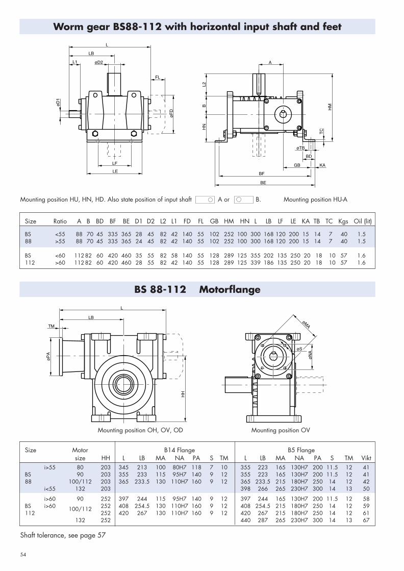
54
LF�
LE�
øD1�
A�
B�
L2�
HN�
BF�
BE�
GB�
BD�
øTB�
KA�
HM�
øFD�
FL�
L�
LB�
øD2�L1�
TC�
øS��
øPA�
øNA�
øMA�
HH�
TM�
LB�
L�
Mounting position OH, OV, OD Mounting position OV
Size Motor B14 Flange B5 Flangesize HH L LB MA NA PA S TM L LB MA NA PA S TM Vikt
i>55 80 203 345 213 100 80H7 118 7 10 355 223 165 130H7 200 11.5 12 41BS 90 203 355 233 115 95H7 140 9 12 355 223 165 130H7 200 11.5 12 4188 100/112 203 365 233.5 130 110H7 160 9 12 365 233.5 215 180H7 250 14 12 42
i<55 132 203 398 266 265 230H7 300 14 13 50
i>60 90 252 397 244 115 95H7 140 9 12 397 244 165 130H7 200 11.5 12 58BS i>60 252 408 254.5 130 110H7 160 9 12 408 254.5 215 180H7 250 14 12 59112
100/112252 420 267 130 110H7 160 9 12 420 267 215 180H7 250 14 12 61
132 252 440 287 265 230H7 300 14 13 67
Shaft tolerance, see page 57
Size Ratio A B BD BF BE D1 D2 L2 L1 FD FL GB HM HN L LB LF LE KA TB TC Kgs Oil (lit)
BS <55 88 70 45 335 365 28 45 82 42 140 55 102 252 100 300 168 120 200 15 14 7 40 1.588 >55 88 70 45 335 365 24 45 82 42 140 55 102 252 100 300 168 120 200 15 14 7 40 1.5
BS <60 112 82 60 420 460 35 55 82 58 140 55 128 289 125 355 202 135 250 20 18 10 57 1.6112 >60 112 82 60 420 460 28 55 82 42 140 55 128 289 125 339 186 135 250 20 18 10 57 1.6
Mounting position HU, HN, HD. Also state position of input shaft A or B. Mounting position HU-A
Worm gear BS88-112 with horizontal input shaft and feet
BS 88-112 Motorflange
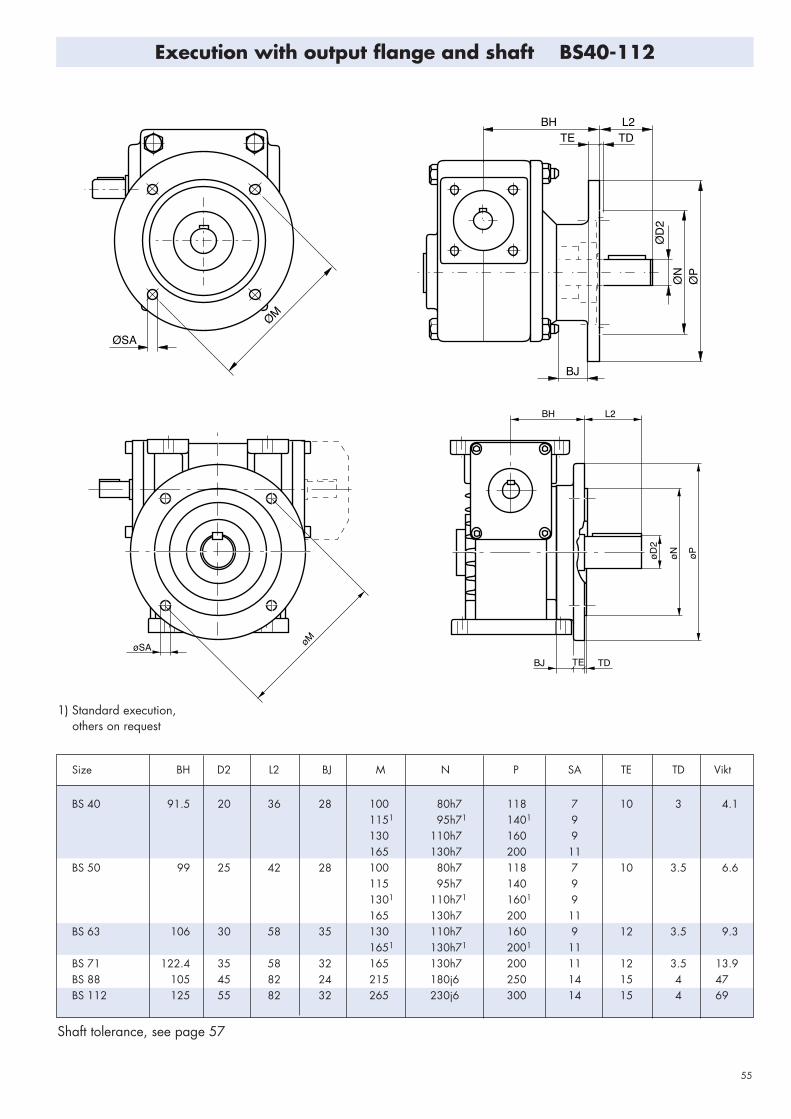
55
øM�
øSA�
BJ� TE� TD�øD2�
øN�
øP�
L2�BH�
ØM�
ØSA�
BH� L2�TD�TE�
BJ�
ØD2�
ØN�
ØP�
Size BH D2 L2 BJ M N P SA TE TD Vikt
BS 40 91.5 20 36 28 100 80h7 118 7 10 3 4.11151 95h71 1401 9130 110h7 160 9165 130h7 200 11
BS 50 99 25 42 28 100 80h7 118 7 10 3.5 6.6115 95h7 140 91301 110h71 1601 9165 130h7 200 11
BS 63 106 30 58 35 130 110h7 160 9 12 3.5 9.31651 130h71 2001 11
BS 71 122.4 35 58 32 165 130h7 200 11 12 3.5 13.9BS 88 105 45 82 24 215 180j6 250 14 15 4 47BS 112 125 55 82 32 265 230j6 300 14 15 4 69
Shaft tolerance, see page 57
Execution with output flange and shaft BS40-112
1) Standard execution, others on request

56
BL� TF�
BO�
�20°�
�20°�
øSB�
LS�LN�
HT�
AK� AS�
AT�
LS�
20°�
HT�
ØS�
Torque arm shall be mountedfor tension (see arrows).
LS
Size AK AS AT BO HT BL LN min/max S SB TF Kgs
BS 40 - - - 9 76 36.5 70 165/245 - 8 4 4.0BS 50 - - - 9 88 39 85 165/245 . 8 5 5.8BS 63 - - - 11 106 41 103 190/290 - 3/8" 5 7.5BS 71 - - - 11 120 50.7 107.5 190/290 - 3/8" 5 10.7BS 88 47 18 - - 190 - 460/600 16 - - 40.0BS 112 60 18 5 - 240 - 480/600 16 - - 57
Execution with torque arm
Size ø B ø BY ø H SA ø SH ø SV RL RS TS TB
BS 35 9 20 7 (8x) 100 70 55 15 42.5 4 12

57
Shaftdimensions and tolerances
Input shaft Hollow shaft Output shaft
Execution with electromagnetic brake
Shaft bushings
Key and locking screws are supplied with each set ofbushes.
Keyway acc. to SMS 2305
Size Brake Brakesize torque
Nm øPB LH LK Vikt02 3 85 115 55 4.6
BS 40 03 5.7 100 120 60 5.204 12.6 116 126 66 6.303 6.4 100 131 60 7
BS 50 04 14.4 116 137 66 8.105 24 137 146 75 10.403 6.4 100 142 60 8.7
BS 63 04 14.4 116 148 66 9.805 24 137 157 75 12.104 16 116 160 74 12.3
BS 71 05 26 137 161 75 14.3
Hollow shaft mm
Size Standard Bushing
BS 88 45 40 35 -BS 112 55 50 45 40
Size Input shaft Hollow shaft Output shaft
D1 F1 G1 DY2 D2 F2 G2 D2 F2 G2
BS 35 30d9 20H7 6JS9 22.8 20j6 6h9 22.5
BS 40 14j6 5h9 16 37d9 20H7 6JS9 22.8 20j6 6h9 22.5
BS 50 19j6 6h9 21.5 40d9 25H7 8JS9 28.3 25j6 8h9 28.0
BS 63 19j6 6h9 21.5 45d9 30H7 8JS9 33.3 30j6 8h9 33 0
BS 71 24j6 8h9 27 50d9 35H7 10JS9 38.3 35j6 10h9 38.0
BS 88 i<60 28j6 Sh9 31 65d9 45H7 14D10 48.8 45k6 14h9 48.5
BS 88 i>60 24j6 8h9 27
BS 112 i<60 35j6 10h9 38 80d9 55H7 16D10 59.3 55k6 16h9 59.0
BS 112 i>60 28j6 8h9 31
Maximum input speed n1
Size35 40 50 63 71 88 112i<60:1 112i>60:1
n1, max rpm 4500 6000 5500 5000 4500 4000 3000 3500
LH�
LK�
øPB�
øD1�
G1�
F1�
�
F2�
øDY2�
øD2�
G2�
�
F2�
G2�
�
øD2�

58
Worm Gearwith environmental
classificationWith BS (size 40-71) classified acc toenvironmental class we are able torecommend the gears for installation inambient conditions where normally
only materials in stainless steel areaccepted. The gears are classified accto environ-mental class M2-M3, Swedishstandard stBK-N4.

59
Advantages:
• No corrosion• Low weight (aluminium)• High rating • IEC-standard
• High surface finish • Modern design• No maintenance • Easy handling • Large number of motor alternatives
Product specification• coated gear case, flanges and feet
• stainless steel bolts in gear housing
• stainless steel hollow shaft ( SS 2346 alt. 2382)
• stainless steel output shaft
• surface for seal ring protected by stainless steel sleeve (SS 2333)
• Seal rings of viton
• ratings acc to catalogue
Type of coating The coating is a recently developed surface coatingmethod for aluminium.The coating means that the material surface is, by achemical process, converted into an aluminium oxide,which gives a very hard, ceramic, surface finish.The oxide layer is then impregnated and coated withplastic. With heat treatment a very strong and resistantconnection between oxide and plastic is created.Unique coating qualities:
• high resistance against corrosion
• very hard and resistant against wear
• Iow tendency to be sticky
• hygienic
Application examples
• food industry
• paper and cellulose industry
• pharmaceutical industry
• chemical industry
• defence industry
• marine and mobile installations
• all outdoor installations
Gear BS 40 BS 50 BS 63 BS 71
Catalogue rating, Nm max 78 120 197 315min 31 62 92 143
Output speed, rpm max 429 358 369 381min 9 9 7 7
Max static load, Nm 93 150 250 400
Radial force on output shaft, N 2000 2700 4000 5000
Thrust load on output shaft, N 2000 2500 3500 4500

60
Applications
BENZLERS
B�A�
øD�
øC�
BENZLERS63
BENZLERSBS 88
BENZLERSBS 88
Size Shrink disc A B øC øD Nm
BS 40 HSD 30-22 119 46 60 20 155BS 50 HSD 36-22 128 49 72 25 350BS 63 HSD 44-22 133 50.5 80 30 440BS 71 HSD 44-22 154 61 80 35 770
Worm gear with shrink fit
Wormed geared motor withplanetary variator
Wormed geared motor with v-belt variator
Wormed geared motor with encoder flange (PGF)

61
Benzlers "electronic" catalogue
We at Benzlers has as one of our goals to continuously help our customers to increase theirprofitability and efficiency. As a step on this road we have made programs for CAD and PC withdrawings and calculation programs for our whole range of gears, which will simplify your selectionof gears. This electronic catalogue will help you with;Selection of gear and geared motor.Documentation of selection and related power demands etc.Detail drawing and Layout drawing.With these programs you will win considerable amount of time in the design stadium and will gainhigher development speed in your own business. Except gaining time the selection will secure thatthe optimal gear combination is selected in each and every case. Thereby the risk for expensivebreakdown will decrease to a minimum and also unnecessary high cost if too big gears are selected .

62
General
1. The gear should be placed on a flat and solidfoundation.
2. Sprocket, pulley or coupling on shaft can not bemounted with force. This will damage the gear.
3. To avoid increasing load on shafts and bearings, thegear and the driven machine should be carefullyaligned, even if an elastic coupling is used.
4. If sprockets are used on the output shaft the preferabledirection of pull should be such that the gear housingwillbe pressed towards the foundation.
5. When situated outdoors or working under adverseconditions as heat, dust or damp, the gear must beprovided with sufficient protection, but the cooling aircirculation must not be unduly restricted.
Mounting
Lubrication
Maintenance
Running in
Before delivery BS40-112 are filled with synthetic oil -Mobil SHC 634 and BS35 with synthetic grease - MobilSHC 007. This type of lubrication is extra suitable forworm gears.
1. Benzler worm gears are lubricated for life with syntheticoil/grease and are therefore maintenance free.
2. Check that there are no leakage.
1.The gear should be run under low load conditionsduring the first 10-30 hours. Then the load shouldgradually be increased to full load.
2.The length of the running-in period depends on the sizeof the gear and the actual working conditions.
Hollow shaft gears
1. The gear is normally mounted on a shaft with tolerancejs6. The hollow shaft have tolerance H7.Grease the shaft with Molykote BR2 or equivalentbefore the gear is mounted. The gear shall not bemounted with force.The gear shall be locked against axiel movement. Setscrews in hollow shaft can be used for BS88 and 112.
At normal condition the oil/grease never needs to bechanged.Ambient temperature -30°C - +30°C.
3. The worm gears shall under no circumstances beentirely filled with oil or grease.
3. When increasing the load the temperature of the gearcan exceed the ambient temperature by 60-70° C. Oil-and geartemperatures of 95-100° C are harmless andhave no influence on the function af the gear. Whenthe temperature exceeds 100° C special sealrings mustbe used.
4. Gears which are not used for a long period should berun for short periods, approximately every third month.

63
Questionaire
To specify a drive precisely, certain data are essential. The most important questions are listed in the table below. If youdo not have the required data available in this form, we advice you to use a technical handbook or other suitabledocumentation. Should you have any question, please do not hesitate to contact us, Benzlers specialists will be pleasedto assist you.
Load designation
Output power (kW): Pe at nmax at nmin MotorEnclosure IP
Output speed (RPM): nemax neminOperating voltage motor (V) brake (V) frequency (Hz)
Output torque (Nm): Te at nmax at nminBrake torque (Nm)
Overhung load (N): Fr2e at output shaft at input shaftAmbient factorsAmbient temperature (°C)
Axial thrust load (N): Fa2e at output shaft at input shaft
(away + / towards -) Load cycle / Duty cycle S / % ED
Moment of inertia (kgm2): at output shaft at input shaft
Starting frequency (1/h)
Unit type and mounting position (see page 11)
Additional information:

SERIES BS
DB Series BS CBS-1.01GBD0808:English Cover (Series F) 06.07 15/8/08 12:28 Page 5