World Orienteering Day OCAD TutorialThis tutorial describes the workflow how to create a base map...
21
World Orienteering Day Creating Orienteering Maps with OCAD Copyright © 1988 – 2017 OCAD AG www.ocad.com
Transcript of World Orienteering Day OCAD TutorialThis tutorial describes the workflow how to create a base map...

World Orienteering Day
Creating Orienteering Maps
with OCAD
Copyright © 1988 – 2017 OCAD AG
www.ocad.com

Copyright © 1988 – 2017 OCAD AG Page 2

Copyright © 1988 – 2017 OCAD AG Page 3
Contents 1 Base Map and Field Work Preparation .......................................................................... 4
1.1 Create the Base Map ............................................................................................... 4
1.1.1 Import the Open Street Map ............................................................................ 4
1.1.2 Online map Service ........................................................................................... 6
1.1.3 Add Contour Lines Background Maps ........................................................... 9
1.2 Prepare the Base Map and Field Work Tools......................................................... 9
1.2.1 Prepare the Base Map for Manual Field Work ............................................... 9
1.2.2 Field Work Tools .................................................................................................. 9
2 Field Work ......................................................................................................................... 11
2.1 Colors and Symbols ................................................................................................. 11
2.1.1 Point Symbols .................................................................................................... 11
2.1.2 Line Symbols ...................................................................................................... 11
2.1.3 Area Symbols .................................................................................................... 11
2.2 Procedure ................................................................................................................. 11
2.2.1 Step measure ................................................................................................... 11
2.2.2 Point Symbols .................................................................................................... 11
2.2.3 Line and Area Symbols .................................................................................... 12
2.2.4 Contour Lines .................................................................................................... 12
3 Digitize the Field Work ..................................................................................................... 12
3.1 Scan Field Work ....................................................................................................... 12
3.2 Draw an Object ....................................................................................................... 12
3.2.1 Draw a Point Object ........................................................................................ 12
3.2.2 Draw a Point Object ........................................................................................ 13
3.2.3 Draw a Point Object ........................................................................................ 13
3.2.4 Draw a Line Object.......................................................................................... 13
3.2.5 Draw an Area Object ...................................................................................... 14
3.2.6 Tips to draw ....................................................................................................... 14
3.3 Edit Objects .............................................................................................................. 15
3.3.1 Move Objects/Vertexes .................................................................................. 15
3.3.2 Move Objects/Vertexes .................................................................................. 15
3.3.3 Move Segments ............................................................................................... 16
3.3.4 Reverse Object Direction ................................................................................ 16
3.3.5 Move Parallel .................................................................................................... 16
4 Layout, Print and Export ................................................................................................. 17
4.1 Layout ....................................................................................................................... 17
4.2 Print and Export ....................................................................................................... 17
5 Sample Maps ................................................................................................................... 18

Copyright © 1988 – 2017 OCAD AG Page 4
1 Base Map and Field Work Preparation
1.1 Create the Base Map
This tutorial describes the workflow how to create a base map with the open street
map data. If you have access to DXF files from the area of your map you can also
use these files of course. You can import the DXF files as well but you have to build up
your own cross reference table (*.crt) to assign the orienteering map symbols to the
imported DXF objects.
1.1.1 Import the Open Street Map
The field work is easier if you have a good base map. Open the OCAD Starter WOD –
Edition to create a base map.

Copyright © 1988 – 2017 OCAD AG Page 5
File New Map Wizard
Dialog New Map Wizard
Choose the Symbol Set: ISSOM
WOD English.ocd.
Set the map scale on a full scale
like 1:500, 1:1000, 1:1500, 1:2000
or 1:5000.
Choose a filename and set the
path to the file below the map
scale.
Next
Choose the area of the map by
searching your town in the
search box in the top left part of
the dialog. The perimeter you
see in the dialog is getting
imported.
Change the coordinate system
to a local system, if it is desired.
Next
Next
Wait a moment until the OSM
data is imported.

Copyright © 1988 – 2017 OCAD AG Page 6
1.1.2 Online map Service
The map is drawn automatically
with the OSM data; therefore the
map does not yet looking good.
Improve the concerned objects
like stairs, buildings, streets,
tunnels and so on.
You should check, if you have
any objects in your map, that
haven’t any symbol. All the
objects without any symbol are
shown with the color red.
Select Select Objects by
Symbol...
Dialog Select By Symbol
Select Objects without Symbol
OK
In the left bottom, you see how
many symbols are selected. The
goal is to have no selected
symbols. But if you have some,
zoom into the map and search
the selected symbols. These
symbols you can delete or you
change them to a symbol by
using the Change Symbol icon
. Make sure that you change
all selected symbols. If you want
to only change one, then you
have to select it single and
reselect the others by the menu.

Copyright © 1988 – 2017 OCAD AG Page 7
You can load an orthophoto as
a background map, if buildings,
streets or other features are
missing on the imported map.
Background Map Online Map
Service
Dialog Online Map Service
Choose a part of the town, park
to import.
Load as background map
May you have to change the
View Mode to Draft Mode to see
the background map.
View Draft Mode
You can see the background
map. A slider bar appears in the
View Toolbar. There you can
change the visibility of the map
(M) and the background map
(B).
May you have to adjust the
background map that It is in the
right position.
Background Map Adjust
Now you have to adjust the
background map with the map:
1. Click on a point on the
background map
2. Click on the same point
on the map
Step 1 and 2 can be repeated.
(Ideally with four points)
Enter key
The Adjustment is executed after
pressing the Enter key. The
1st click
178000/619000
on the background map
2nd click
178000/619000
on the map

Copyright © 1988 – 2017 OCAD AG Page 8
background map is rotated and
stretched to get the best fit for
the adjustment points.
Background Map Manage...
Dialog Manage Background
Maps
You can click In the left column
V to make the background map
visible or not.
Check the third column T to
make a background map
transparent.
Open or Remove the
background maps with the
buttons at the bottom
Now you see the orthophotos at
the correct position and you can
complete the missing features.
1+2
Coordinate
178000/619000
adjusted

Copyright © 1988 – 2017 OCAD AG Page 9
1.1.3 Add Contour Lines Background Maps
1.2 Prepare the Base Map and Field Work Tools
For the field work you either use a tablet computer or do it manual. An advantage of
a tablet computer is that you don’t have to redraw your field work at home on the
computer. OCAD 12 requires a tablet computer with Windows 7, 8 or 10 (32 or 64 bit).
1.2.1 Prepare the Base Map for Manual Field Work
Print the base map for the field work in a scale that is usually a bit larger than the
scale of the map. An appropriate scale for a map with scale 1:2000 is 1:1000. It helps
to adjust the scanned field work later if the base map is printed with the grid.
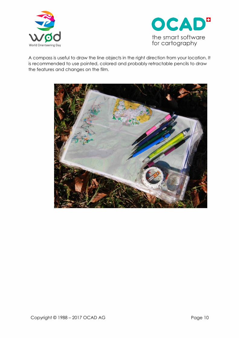
1.2.2 Field Work Tools
You need a carton or a plastic board for the underlay of the field work. It is
recommended to cover the printed base map with a film. This makes it easier to
change the drawn objects.
You should also have the
contour lines on the base map.
Find a map with contour lines on
the GIS websites of your country,
state or town. You can open the
map as a background map
(supported formats: BMP, GIF,
JPEG, PNG, TIFF).
Background Map Open
Choose the file
Dialog Background Map
If the map is georeferenced click
on OK, else set the Resolution,
Draft scale and the angle. OK
If the map isn’t georeferenced,
you have to adjust it.
Now you can redraw the
contour lines from the
background map.
Copyright © 1988 – 2017 OCAD AG Page 10
A compass is useful to draw the line objects in the right direction from your location. It
is recommended to use pointed, colored and probably retractable pencils to draw
the features and changes on the film.

Copyright © 1988 – 2017 OCAD AG Page 11
2 Field Work
2.1 Colors and Symbols
You should use the same colors and symbols on the field work, like it would be on the
orienteering map, because the interpretation of the field work would be easier when
you redraw the map on the computer.
2.1.1 Point Symbols
For the point symbols like knolls, stones, pits, trees and fountains use the IOF –
Symbols. But there are other special symbols for the school yard map like a street
lamp, flagpole, climbing pole or a bench. Take a look in OCAD to see the available
symbols. You can also map additional symbols, if you think it is necessary.
2.1.2 Line Symbols
For the line symbols use also the IOF – Symbols from the orienteering map. You can
use the lines for other objects like the distinct vegetation boundary for the edge of a
place, a sea outline for an edge of a street or an impassable cliff for an impassable
wall.
2.1.3 Area Symbols
To understand the finished map better, take different colors to draw the facilities,
places, paths and streets. Take colors that are typical for the facility (e.g. athletics
track red).
It is important to see for the runners if the line and area symbols are passable or not.
2.2 Procedure
2.2.1 Step measure
It is more important to draw the object right relative to the others than exactly true-
to-location. It is enough to measure it with steps. You can train on a 100-meter track
or another track with known length to have a step measure of 1 meter,
2.2.2 Point Symbols
You locate the point symbols with the help of the step measure and the compass.
Also a help is the vanishing point of buildings. Objects that are difficult to locate
should be measured with the compass from various points:
• Known position
• Draw a line in the right position that you have measured with your compass.
• Take another known position that is 60°-90° degrees away of the first position.
• Take a third position to have a control.
• Three lines should be intersected at one point. There is the location of the object.

Copyright © 1988 – 2017 OCAD AG Page 12
2.2.3 Line and Area Symbols
The most line and area symbols are already on your base map, but if there is a
building or track that isn’t on the map, you have to draw it. Take a known position
and draw the direction of the line symbol with the compass. Take the length of the
object by the step measure and so on. Do the same for area features by following
their border.
2.2.4 Contour Lines
It is possible that the contour lines on the base map do not represent the relief very
well. You are free to move them to get a better terrain representation. You can also
use a form line to show the relief between two contour lines.
3 Digitize the Field Work
3.1 Scan Field Work
Scan your field work and save it in a raster format (JPG, TIFF, PNG). Open the field
work as a background map, like it is explained in the base map chapter.
3.2 Draw an Object
In these tutorials are only the basic explained. If you want to know more, you can
look on the OCAD Wiki or take a look at this document:
http://www.ocad.com/docs/Drawing_Orienteering_Maps_in_OCAD_12.pdf
It is recommended to draw the point and line objects first and at the end the area
objects, because they cover the background map.
3.2.1 Draw a Point Object
To draw a point object, choose a
point symbol in the symbol box and
click on it.
Select any drawing mode and click in
the drawing area.
The object is orientated to the north. If
you want to orientate it by yourself,
you have to click in the drawing area
and move it to the right direction while
you are pressing the left mouse button.

Copyright © 1988 – 2017 OCAD AG Page 13
3.2.2 Draw a Point Object
To draw a point object, choose a
point symbol in the symbol box and
click on it.
Select any drawing mode and click in
the drawing area.
The object is orientated to the north. If
you want to orientate it by yourself,
you have to click in the drawing area
and move it to the right direction while
you are pressing the left mouse button.
3.2.3 Draw a Point Object
To draw a point object, choose a
point symbol in the symbol box and
click on it.
Select any drawing mode and click in
the drawing area.
The object is orientated to the north. If
you want to orientate it by yourself,
you have to click in the drawing area
and move it to the right direction while
you are pressing the left mouse button.
3.2.4 Draw a Line Object
Choose a line symbol in the symbol
box.
Now you have different options to
draw the lines.
1. Take the Straight Line Mode, if
you want to draw straight lines.
Click and hold the mouse
button to draw a line.
2. Take the Curve Mode to draw
a curve. Click in the drawing
area and move the cursor to
draw the tangent on the line
and release the mouse button.
Click on the next point to add
a vertex.

Copyright © 1988 – 2017 OCAD AG Page 14
3. You can draw with a mix
between the Curve Mode and
the Straight Line Mode.
Options OCAD Preferences...
Categories: Drawing and
Editing
Select the Curve mode:
change to straight line mode
when clicking in drawing area.
Select the Curve Mode.
If you drag the mouse, you are
drawing a curve and if you
click without dragging, you
draw a straight line.
3.2.5 Draw an Area Object
Choose an area object in the symbol
box.
You have different options to draw the
areas.
1. Take an option of the line
modes.
2. Select the Rectangular Mode:
Click on the first corner of the
area. Hold the mouse button,
drag the cursor along the
longer side to the next corner
and release the mouse button.
3. Select the Circle or the Ellipse
Mode: Click on the edge of the
area and drag the mouse
button to the other side and
release it. If you want to draw
an area you have to click again
and drag along the other axis.
3.2.6 Tips to draw
You also can follow existing objects, fill it, or continue an existing object. How to do
that look in the Tutorial: Drawing Orienteering Maps in OCAD.
Copyright © 1988 – 2017 OCAD AG Page 15
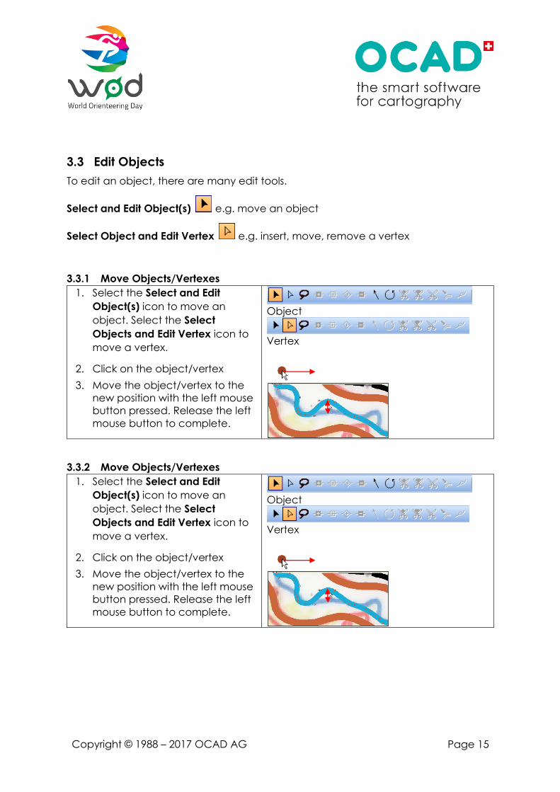
3.3 Edit Objects
To edit an object, there are many edit tools.
Select and Edit Object(s) e.g. move an object
Select Object and Edit Vertex e.g. insert, move, remove a vertex
3.3.1 Move Objects/Vertexes
1. Select the Select and Edit
Object(s) icon to move an
object. Select the Select
Objects and Edit Vertex icon to
move a vertex.
2. Click on the object/vertex
3. Move the object/vertex to the
new position with the left mouse
button pressed. Release the left
mouse button to complete.
Object
Vertex
3.3.2 Move Objects/Vertexes
1. Select the Select and Edit
Object(s) icon to move an
object. Select the Select
Objects and Edit Vertex icon to
move a vertex.
2. Click on the object/vertex
3. Move the object/vertex to the
new position with the left mouse
button pressed. Release the left
mouse button to complete.
Object
Vertex
Copyright © 1988 – 2017 OCAD AG Page 16
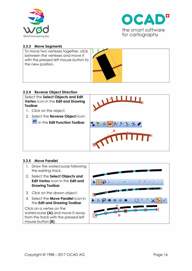
3.3.3 Move Segments
To move two vertexes together, click
between the vertexes and move it
with the pressed left mouse button to
the new position.
3.3.4 Reverse Object Direction
Select the Select Objects and Edit
Vertex icon in the Edit and Drawing
Toolbar.
1. Click on the object.
2. Select the Reverse Object icon
in the Edit Function Toolbar.
3.3.5 Move Parallel
1. Draw the watercourse following
the existing track.
2. Select the Select Objects and
Edit Vertex icon in the Edit and
Drawing Toolbar.
3. Click on the drawn object.
4. Select the Move Parallel icon in
the Edit and Drawing Toolbar.
Click on a vertex on the
watercourse (A) and move it away
from the track with the pressed left
mouse button (B).

Copyright © 1988 – 2017 OCAD AG Page 17
4 Layout, Print and Export
4.1 Layout
The following information should appear on the map:
• Name of the map
• Scale
• Equidistance
• Date
• Nord Lines and Nord Arrow
• Name of the subscriber
• Editor
• Legend
• Logos
4.2 Print and Export
You have the possibility to export or print your map.
File Print to print your map directly from the OCAD.
File Export to export your map as a PDF or other formats.

Copyright © 1988 – 2017 OCAD AG Page 18
5 Sample Maps

ALFREDSHÄLLSKOLAN
0 25 50m Höjdskillnad 2 m
Skala 1:1000
Odlad mark, gräsmattaHalvöppen markÖppen mark i skog
Mjukt underlagTät skog
Tomt, rabatter, blommor
Sandyta
Rabatt, buskar
Hus, byggnadSkärmtakHårt underlag, asfalt, grusBordtennisbordVatten
Liten stigStaket, opasserbar
Häck, rabattBeståndsgräns
Väg, parkväg
OBS! Här får man inte springa!
Skog
Träd; stort och litetBrunn/bänkLampa/stolpe, flaggstångSten, skulptur/lekställning
BalansstockarTrappa
Staket, cykelställMur, opasserbarMur, passerbar
GungställningHöjd
Teckenförklaring
24 maj 2017
Kartan ritad av: Göran Andersson,[email protected] 53 26

Fjällbacka skola
LogoHOVEDLOGOHovedlogo skal benyttes i alt materiell, både på trykk og digitalt, dersom ikke forholdene krever noe annet.
ProcessCMYK xxxxRGB xxxxxHEX xxxxx
Vit text, 25 cm lång
LogoHOVEDLOGOHovedlogo skal benyttes i alt materiell, både på trykk og digitalt, dersom ikke forholdene krever noe annet.
ProcessCMYK xxxxRGB xxxxxHEX xxxxx
Vit text, 25 cm lång
Teckenförklaring
Hus, byggnadSkärmtak, berg i dagenOdlad mark, gräsmatta
SandytaÖppen mark i skog
Hårt underlag med sten
Halvöppen mark
Hårt underlag, asfalt, grus
Tät skogTomt, rabatter, blommorVäg, parkvägStor stig/liten stigStaket, opasserbar
Mur, plank, opasserbarBord/blomsterrabattHäck, hög rabatt
Fotbollsmål/parkbänkTräd; stort och litetUtmärkande träd/buskeTrappa
Staket/cykelställ, passerbar
OBS! Här får man inte springa!
Skog
Sten, betongklump/brunnSpiraltrappa/lekställningHöjdkurvor/lutningsstreckLiten höjd/stock, mur
Flaggstång, liten stolpeStörre stolpe, lyktstolpe
Klätterställning, kanonerDikeBrant, opasserbar
Klubb: Kvillebyns Sportklubb Kontakt: Magnus DanielsonE-mail: [email protected] ritad av: Göran Andersson,[email protected]
0 15 30 45 60 75m Höjdskillnad 2 m
Skala 1:1500

Svanberga skola, Norrtälje År 7-9
Teckenförklaring
Hus, byggnadSkärmtak, berg i dagenOdlad mark, gräsmatta
Halvöppen markSandyta
Hårt underlag, asfalt, grus
Undervegetation
Öppen mark i skog
Tät skogTomt, rabatter, blommorVäg, parkvägStor stig/liten stigStaket, opasserbar
Mur, plank, opasserbarBord/blomsterrabattHäck, hög rabatt
Fotbollsmål/parkbänkTräd; stort och litetUtmärkande träd/buskeTrappa
Staket, passerbar
OBS! Här får man inte springa!
Skog
Sten, betongklump/brunnPelare/lekställningHöjdkurvor/lutningsstreckLiten höjd/stock, mur
Flaggstång, liten stolpeStörre stolpe/lyktstolpe
BeståndsgränsVattendikeBrant, opasserbar
Skola: Svanberga skolaInformation: Erica Samuelsson,[email protected] ritad av: Göran Andersson,[email protected]
0 25 50 75 m Höjdskillnad 1 m
Skala 1:2000