Workshop on the Role of the CVA for Offshore Wind Farms on ... · 4.1.3 Transportation/ Loadout...
115
Offshore : Risk & Technology Consulting Inc. Malcolm Sharples (ORTC), Kent Dangtran (DOTC) & Partha Ganguly (MTC) Workshop on the Role of the CVA for Offshore Wind Farms on the OCS Project No. 633, Contract M09PC00015 Prepared for: Bureau of Ocean Energy Management, Regulations and Enforcement Department of the Interior This report has been reviewed by the Bureau of Ocean Energy Management, Regulations and Enforcement and approved for publication. Approval does not signify that the contents necessarily reflect the views and policies of the Service, nor does mention of trade names or commercial products constitute endorsement or recommendation for use. November 2010
Transcript of Workshop on the Role of the CVA for Offshore Wind Farms on ... · 4.1.3 Transportation/ Loadout...

Offs
hore
: R
isk
& T
echn
olog
y C
onsu
lting
Inc.
Mal
colm
Sha
rple
s (O
RTC
), K
ent D
angt
ran
(DO
TC) &
Par
tha
Gan
guly
(MTC
)
Workshop on the Role of the CVA for
Offshore Wind Farms on the OCS
Project No. 633, Contract M09PC00015
Prepared for: Bureau of Ocean Energy
Management, Regulations and Enforcement
Department of the Interior
This report has been reviewed by the Bureau of Ocean Energy Management, Regulations and Enforcement and approved for
publication. Approval does not signify that the contents necessarily reflect the views and policies of the Service, nor does mention of trade names or commercial products constitute endorsement or
recommendation for use.
November 2010

BOEMRE SERVICE CONTRACT
Workshop on the Role of the CVA for Offshore Wind on the OCS
2

BOEMRE Order No. M09PC00015 CVA Workshop, New Orleans 21-22 Oct., 2010
Front Page Acknowledgement– Kuhn M. (2001), Dynamics and design optimization of OWECS, Institute for Wind Energy, Delft Univ. of
Technology
TABLE OF CONTENTS 1. 2 2. PURPOSE OF THE WORKSHOP................................................................................. 2 3. DEFINITION OF THE CVA.......................................................................................... 2 4. PLAN AND REPORT SUBMISSIONS TO BOEMRE................................................ 3
4.1 CVA Activities.......................................................................................................... 4 4.1.1 Design Review by CVA and Issues Related thereto:......................................... 4 4.1.2 Fabrication Review by CVA and Related Issues............................................... 6 4.1.3 Transportation/ Loadout /Installation Review by CVA and Related Issues ...... 8
Note remarks on Appendix J which also applies to this section, and which are contained in 4.1.2. 5. CVA QUALIFICATIONS AND STIPULATED ACTIVITIES.................... 10 5. CVA QUALIFICATIONS AND STIPULATED ACTIVITIES.................................. 11
5.1 Qualifications.......................................................................................................... 11 5.2 Information on the CVA role in Offshore Wind Farms is stipulated in the Code of Federal Regulation (30 CFR §285)............................................................................... 12 5.3 CVA for Oil and Gas Structures –from 30 CFR §250.909 – 918........................... 15
6. RESULTS ..................................................................................................................... 16 APPENDIX A: AGENDA...................................................................................... 17 APPENDIX B: BOEMRE Background Info and Workshop Goals ....................... 20 APPENDIX C: CVA Expected Activities: Surveillance and Design..................... 24 APPENDIX D: Offshore Wind Energy Workshop, New Orleans ......................... 48 APPENDIX E: Facility Design Review ................................................................. 55 APPENDIX F: Bureau Veritas and Offshore Wind Farm Fabrication................... 59 APPENDIX G: ABS Thoughts on CVA Process for Offshore Wind Farm Surveillance, Transportation, & Installation............................................................. 65 APPENDIX H: Certification of the complete project: How to deal with the uncertainties and with site specific turbine certification........................................... 71 APPENDIX I: Recap of the O&G CVA Process................................................... 79 APPENDIX J: CVA WORKSHEET LOADOUT/ TRANSPORTATION / INSTALLATION & COMMISSIONING................................................................ 81 APPENDIX K: DESIGN CVA WORKSHEET..................................................... 84 APPENDIX L: RECOMMENDATIONS: ............................................................. 94
APPENDIX M: WORKSHOP PARTICIPANTS
INTRODUCTION ..........................................................................................................
................................................ 109

BOEMRE Order No. M09PC00015 CVA Workshop, New Orleans 21-22 Oct., 2010
1. INTRODUCTION
A workshop was held at New Orleans on October 21-22, 2010 on the Role of the Certified Verification Agent (CVA) for Offshore Wind Structures.
The Bureau of Ocean Energy Management, Regulations and Enforcement (BOEMRE) requirements are set out in the Code of Federal Regulations Title 30, Part 285. The activities and amount of attendance/ surveillance, and the depth of examination as stipulated in the CFR are subject to interpretation. This workshop was intended to add some definition as to how best to fulfill the CVA role.
2. PURPOSE OF THE WORKSHOP The purpose of the workshop was to produce a set of recommendations to BOEMRE from the workshop participants as to the detailed activities of the CVA for the design, fabrication and installation of wind energy structures on the Outer Continental Shelf of USA. The idea of the program at the workshop was to start with the degree, type and amount of surveillance to be carried out by the CVA for the various stages i.e. verification of design, fabrication, transportation & installation. The intention was that if the surveillance can be decided upon by the participants, then it may be an easier task to settle on the amount and type of calculation or check on calculations that can/should be done. The logical sequence of events starts with design, however, for the workshop it started from the transportation & installation phase and worked backwards. The reason for this was to tackle an easier problem first, get a “win” under our belts, and then tackle the more difficult issues.
3. DEFINITION OF THE CVA Per 30 CFR §285, Certified Verification Agent (CVA) means an individual or organization, experienced in the design, fabrication, and installation of offshore marine facilities or structures, who will conduct specified third-party reviews, inspections, and verifications in accordance with this part.
The intent at the workshop was that we should discuss the activities to be reviewed for the CVA function, with the fact in mind that the CVA while paid for by the owner, is in the business of certifying for regulatory purposes (whatever we may perceive them to be). The production of the certification reports do not necessarily mean that the system will work, will be productive etc.: they are merely evidence that the structures and any components necessary for structural integrity are, in the opinion of the CVA , at the start of production, in compliance with appropriate regulatory requirements.
The specific citations in 30 CFR §285 pertaining to CVA activities are: 285.705 When Must I Use A Certified Verification Agent (CVA)? 285.706 How Do I Nominate A CVA For MMS Approval? 285.707 What Are The CVA's Primary Duties For Facility Design Review?

BOEMRE Order No. M09PC00015 CVA Workshop, New Orleans 21-22 Oct., 2010
285.708 What Are The CVA's Or Project Engineer's Primary Duties For Fabrication And Installation Review? 285.709 When Conducting Onsite Fabrication Inspections, What Must The CVA Or Project Engineer Verify? 285.710 When Conducting Onsite Installation Inspections, What Must The CVA Or Project Engineer Do? 285.712 What Are The CVA's Or Project Engineer's Reporting Requirements? 285.713 What Must I Do After The CVA Or Project Engineer Confirms Conformance With The Fabrication And Installation Report On My Commercial Lease? 285.714 What Records Relating To SAPs COPs And GAPs Must I Keep?
4. PLAN AND REPORT SUBMISSIONS TO BOEMRE
SAP - Site Assessment Plan – Is the plan that describes the process and related activities pertaining to meteorological or oceanographic site related data collection needed to characterize the commercial lease. CVA nomination or a request to waive the requirement for the CVA is made in this submittal. (30 CFR §285.610) (Note: per 30 CFR 285.605(d), a CVA nomination is only required in the SAP if BOEMRE deems the facility or facilities (i.e., met tower) to be “complex or significant” – then the requirements of Subpart G apply which include the requirement for a CVA as well as the requirement for a Facility Design Report (FDR) and Fabrication & Installation Report (FIR)).
COP – Construction and Operations Plan – The COP is the plan that describes the construction, operation and conceptual decommissioning activities for the commercial lease development demonstrating that the lessee is prepared to conduct the proposed activities. The CVA nomination or a request to waive the requirement for the CVA is made in this submittal (30 CFR §285.626 ).
GAP – General Activities Plan – The GAP describes the operator’s planned activities for a limited lease, Right-of-Way (ROW) grant, or Right-of-Use and Easement (RUE) grant. It is submitted in lieu of a SAP and COP, and includes information similar to what is required in a SAP as well as additional information concerning planned activities throughout the term of the lease or grant. The CVA nomination or a request to waive the requirement for the CVA is made in this submittal (30 CFR §285.645). (Note: per 30 CFR 285.645(c), a CVA nomination is only required in the GAP if BOEMRE deems the facility or facilities (i.e., met tower) to be “complex or significant” – then the requirements of Subpart G apply which include the requirement for a CVA as well as the requirement for a Facility Design Report (FDR) and Fabrication & Installation Report (FIR)).
Facility Design Report and Fabrication and Installation Report – These are the Report(s) required to be submitted to the BOEMRE prior to fabrication and installation activities. For a SAP and GAP, a FDR and FIR are only required to be submitted if the facility or facilities are deemed by BOEMRE to be “complex or significant.

BOEMRE Order No. M09PC00015 CVA Workshop, New Orleans 21-22 Oct., 2010
These reports are required to be certified by the CVA (or the Project Engineer – if appropriate BOEMRE waiver is obtained) to be in accordance with the approved SAP, COP and GAP as appropriate. (30 CFR §285.701). The CVA must certify in the Facility Design Report that the facility is designed to withstand the environmental and functional load conditions appropriate for the intended service life at the proposed location (30 CFR 285.707(a)). The CVA must certify in a separate report that the project components are fabricated and installed in accordance with accepted engineering practices; the approved SAP, COP, or GAP; and the Fabrication & Installation Report (30 CFR 285.708(a)(5)). • You must use a CVA to review and certify the Facility Design Report (FDR), the
Fabrication & Installation Report (FIR), and the Project Modifications & Repairs Report. (30 CFR 285.705)
• If you are required to use a CVA, the FDR must include one paper copy of the following certification statement: “The design of this structure has been certified by a MMS approved CVA to be in accordance with accepted engineering practices and the approved SAP, GAP, or COP as appropriate. The certified design and as-built plans and specifications will be on file at (given location).” (30 CFR 285.701(d))
• If you are required to use a CVA, the FIR must include one paper copy of the following certification statement: “The fabrication and installation of this structure has been certified by a MMS approved CVA to be in accordance with accepted engineering practices and the approved SAP, GAP, or COP as appropriate. The certified design and as-built plans and specifications will be on file at (given location).” (30 CFR 285.702(c))
4.1 CVA Activities
The CVA activities are stipulated in 30 CFR §285.705, which are as follows:
• Reviews and certifies the Facility Design Report, the Fabrication and Installation Report, and the Project Modifications and Repairs Report if applicable;
• Ensures facilities are designed, fabricated, and installed in accordance with accepted engineering practices and the above reports;
• Ensures repairs and modifications are performed per accepted engineering practice; and
• Provides BOEMRE with immediate reports of all incidents affecting design, fabrication and installation.
4.1.1 Design Review by CVA and Issues Related thereto: The CVA Facility Design Review entails review of the design to ensure active and passive elements that affect structural integrity are designed as per the Facility Design Report. The specific details pertaining to the extent of the review by the CVA are addressed in the “Design CVA Activities” spread sheet in Appendix K- Facility Design Worksheet.

BOEMRE Order No. M09PC00015 CVA Workshop, New Orleans 21-22 Oct., 2010
DNV provided a presentation to kick-off discussion of the Design Review by the CVA. It is found in Appendix E.
Key items of interest to the attendees that were discussed in more detail were based on and limited to only those that relate to the structure integrity and are as follows:
It has been recommended that the Design CVA attend a hazard identification workshop (HAZID) at the commencement of the design work, hosted by and for the benefit of the stakeholders to define the loads and load combinations and understand the design limitations and the risks being taken. This is particularly important on the East and Gulf Coasts of the United States because the hurricane loads and times for passing of hurricanes MAY not have been appropriately addressed in the IEC Code. Germanischer Lloyd has also seen fit to add some load cases in their Offshore Wind Certification requirements that have been seen as appropriate and they may add further ones to deal with tropical revolving storm areas.
There are a number of questions that were asked about the soil sampling e.g. reviewing the logs of activities and issues during sampling – BUT – it was noted that 30 CFR §285 does not require a CVA to be present during soil sampling activities. While there was some discussion that ensued out of interest at the workshop – it was not directly relevant to the currently stipulated CVA activities. It was noted that 30 CFR 250 mandated soil samples at each piling location within 500 feet, and some at the workshop were of the opinion that this requirement should apply to offshore wind farms. Items such as this were put onto a “parking lot” for later consideration either as a recommendation or as a point of discussion.
Another activity we struggled with was how the software that controls (for example: the yaw gears that are important to structural integrity) be examined. For the most part the software is proprietary and thus may not be able to be examined in detail except as a “black-box” and tested for functions, which may be initially anticipated at commissioning. It was necessary to define the activities of the CVA to verify the software. The yaw system and how to assure the electrical power to yaw continuously and with sufficient response in a given storm was discussed at length.
The requirements of the Part 1- Template for Structure, Equipment and Systems of this Study for the risk studies/meetings which can be found at http://www.boemre.gov/tarprojects/633.htm Report AD, are summarized below:
Provide a Failure Mode and Effect Analysis (FMEA) backed up where clarity for acceptance is required with a Quantitative Risk Analysis (QRA) to provide basis for extreme load cases. Particularly relevant will be any condition that relies upon power or the control system for tower survival. The QRA should analyze and summarize all conditions that could lead to tower or support structure failure and return period applicable to survival of the tower for each condition. The FMEA should identify all assumptions for which the structural integrity depends e.g. details of braking system if emergency stopping is safety critical: the loads will depend on assumptions made with

BOEMRE Order No. M09PC00015 CVA Workshop, New Orleans 21-22 Oct., 2010
the deceleration value due to braking, and substantiation that this is a maintainable value may be critical; yaw angles used for calculating the load should be justified if safety critical; battery longevity may also be a safety critical assumption which should be disclosed.
For both the wind towers and any transformer platform(s), provide details of collision criteria, and loads assumed in the derivation of an appropriate criteria: size of vessel appropriate, speed of collision, and other assumptions that determine the load value together with a copy of the HAZID or other rationale for determining the suitable size and speed. Provide details of collision design requirements, and protection requirements from collision e.g. fendering loads to prevent damage from attending vessels.
Provide copy of the HAZID conducted to decide the design issues with access.
• The HAZID should contain information about the risks of health and safety for the type of access system being used e.g. Ladders (with fall arrest systems and intermediate platforms)
• Elevators • Climb Assists • Helicopters
The HAZID ensures all stakeholders are on board with the definition of loads for the design.
Another key design issue that the workshop struggled with is whether the CVA’s task is to repeat the calculations of the effects of loads (as is stipulated in the IEC Code), or merely to ensure that the results appear plausible/ sensible. If the Type Certifier or Project Certifier has carried out such an independent analysis, it was asked if this would be sufficient for purposes of the CVA.
The recommended design requirements listed in Part 1 were used as the basis of a modified list found in Appendix K. The workshop participants reviewed this document line by line, and adjustments were made to the text to satisfy comments that were made.
Appendix K Design CVA Worksheet lays out the Items of Proposed Design Information, followed by the Proposed CVA activity in Design. (This may vary somewhat as a result of the owner’s proposal to BOEMRE in the Facility Design Report). The proposed CVA Activity notes whether there is no activity because it is not a CVA duty, and if it is a CVA duty notes the activity.
4.1.2 Fabrication Review by CVA and Related Issues The CVA’s duties for Fabrication and Installation review are stated in 30 CFR §285.708. The CVA surveillance activities related to Fabrication, Loadout –Transportation – Lifting and Installation are tabulated in the spread sheet “Surveillance CVA Activities” in Appendix J “CVA Worksheet Loadout/Transportation/Installation and Commissioning.

BOEMRE Order No. M09PC00015 CVA Workshop, New Orleans 21-22 Oct., 2010
Special topics that evoked additional discussions amongst the participants are described below.
For the Fabrication CVA – for the oil and gas industry there are often 3 or 4 main components to the structure, thus the CVA can examine the fabrication quality control system at a limited number of sites and spot-check the documentation, providing samples to augment the CVA Report to BOEMRE. That activity is much more difficult for offshore windfarm structures with multiple components from multiple suppliers, many of which affect the structural integrity and which only come together in the marshalling yard (port from which the installation proceeds). Type Certificates, Manufacturing Certificates and variety of other Certificates have been typically used in the wind turbine business for components; however, serial failures have resulted from items that are Certified. It is also important to know the underlying standard used upon which the Certificate was based. For components (e.g. a blade), the Type Certificate may only cover, the certification of the first component (prototype) off the assembly line, and (often but not always) a Manufacturing Certificate confirmation that the quality system can produce carbon copies of the tested prototype for at least a year (before a visit is made to confirm for another year). A test may be carried out or may be omitted by agreement. For logistical, timing and cost reasons it is probable that the blade (and other parts) will come as a Type Certified system. Our workshop’s task was to define the activity of the CVA and what should be done in the way of checks. One possible outcome was that the CVA should examine the basis of the Type Certification i.e. to ensure that the fabricated component reflects acceptability with the underlying standard. If no other Certifier has endorsed the component for the site activities (e.g. Project Certifier) then the CVA examines any tests carried out on the component to ensure that the tests did not reveal characteristics that would make the component inappropriate to the site. The attendance at the test would not be necessary if the equipment had a Type Certification. If, however, the component is delivered without a Type Certificate then the CVA should have to go through a similar process to Type Certification to confirm the necessary pre-verification documentation to proceed with the CVA activities.
Fabrication activities may apply to the following components. The activities were considered by the workshop participants:
Tower Tower Foundation Blades Bolt Connections Coating Cathodic Protection Control Monitoring Fire Suppression Lightning Protection Gearbox Yaw system Pitch system Drive Train Brakes and Locking Devices Hydraulic System HVAC Generator incl. Bearings Transformers, Battery Charging Equip. Battery J-Tubes & Landings Switchgear & Protection Eq. Transformer Station Cables Nacelle Cover Spinner Housing Nacelle Frame In-Field Cables Cables to shore Structure of Crane (if fitted) Nav. Lights.

BOEMRE Order No. M09PC00015 CVA Workshop, New Orleans 21-22 Oct., 2010
Note: a complete set of likely components for the CVA’s attention is found in the Part 1- Template for Structure, Equipment and Systems Section 1.4, which can be found at http://www.boemre.gov/tarprojects/633.htm Report AD.
The CVA activities were limited to only those that relate to the structure integrity.
Bureau Veritas made a presentation on Fabrication CVA Activities and this presentation is provided in Appendix F.
Listed in Appendix J is a set of proposed surveillance activities to be performed by the CVA. The workshop participants reviewed this document line by line, and adjustments were made to the text to satisfy comments that were made.
Appendix J Surveillance CVA Activities lays out the list of major components making up the wind farm. The definitions of those items are given in the cover sheet to Appendix J. Two different options were proposed to satisfy the fabrication CVA requirement: one where the equipment arrived at site with a Type Certification and one where it did not. Separate proposed activities were listed for Loadout-Transportation-Lifting, for Installation, and for Commissioning. (This may vary somewhat as a result of the owner’s proposal to BOEMRE in the Facility Design Report). The proposed CVA Activity notes whether there is no activity (-NA-) because it is not a CVA duty. Items and explanations are added as appropriate.
4.1.3 Transportation/ Loadout /Installation Review by CVA and Related Issues
In regard to transportation, for oil and gas platforms the CVA attends at the site of departure of the completed base structure from the shipyard, attends at arrival at final location in the OCS, inspects and notes any damage from the voyage, and notes the captain’s log from the transportation to confirm there has been no overload due to motions. The CVA attends the installation but there is no prescriptive tasks other than to observe compliance with approved installation process and report damage so that the damage can be appropriately repaired (if applicable), and that at the time of start-up the oil and gas facility is “intact” as per the design.
In regard to transportation, the offshore wind farm CVA’s task may be somewhat more complex. Multiple components are transported to site from multiple locations around the world. The inspection prior to departure and upon arrival for each component and examination of both marine logs and trucker logs would be an expensive duplication of the quality system documentation that may (should) take place. It was thus important to discuss what extent should a CVA be involved in the transportation of each blade to the marshalling yard, and from the marshalling yard to site; and for the turbine structure, turbine, gear boxes, cabling etc. The workshop tackled these issues with the initial proposal that the work of the CVA on transportation starts at the marshalling yard. If this was not to be the case, it would probably be necessary to ensure logs of daily activities

BOEMRE Order No. M09PC00015 CVA Workshop, New Orleans 21-22 Oct., 2010
are produced in order to verify the motions of the components that undergo during transportation. It is noted that the IEC Code calls for a certification of the documentation that the manufacturer produces to state the limitations on the equipment and tiedowns etc. However, the IEC does not stipulate a way to see if an actual overload took place with the equipment en route to the final location. Our start point was to look for each component as to what the transportation CVA should do in the way of surveillance, and in the way of auditing the paperwork.
Loadouts were part of the discussion. There are so many items loaded out with the numerous components that after discussion it was deemed appropriate that the method of loadout be checked by the CVA against the manufacturer requirements with a plausibility check, and ensuring the manufacturer’s documents were followed to the extent that structural integrity of the final project depended on them. The CVA could observe some of those loadouts as appropriate as a spot check.
For installation it was necessary to carefully define the activities of the CVA. The blades and tower structure are usually bolted into place. The questions facing the workshop were: • Should the CVA check the torque on every bolt? • Spotcheck the bolt torque? Or • Just ensure that torque wrenches are being used and that there is a procedure for
using and calibrating them? Since the CVA probably needs to examine daily logs of torques, then it is necessary to mandate that those are recorded.
• Should the alignment of the tower pieces be checked to ensure they fit together without gaps as the tolerance needs to be tight?
• To what extent does the CVA need to ensure that the electric submarine cable is terminated properly?
o That the installation into the J-tube does not damage the cable? o That the J-tube itself is robust to protect the cable (more of a design
issue)? o That the cable laying itself is observed by the CVA to ensure there is not
potentially damaged area? Although the cable is not typically part of a structural integrity check, if the turbine structural capability depends on the ability of the structure to yaw, then it may be important (depending on battery life, and likely duration of storm), that the cable is intact to protect the structure against collapse.
• How much should the CVA be physically present at site observing the installation? Should he be there for each pile nailed into place?
o A representative number of piles? o Or just at the first one, part way through and final one? o Should he examine documentation i.e. logs of daily activities to assess the
acceptability of the driven piles? (then there needs to be a requirement to actually keep logs).

BOEMRE Order No. M09PC00015 CVA Workshop, New Orleans 21-22 Oct., 2010
Commissioning was proposed as part of the installation activity e.g. software for control, shut down in high winds, backup to the yaw system etc. and thus became part of the discussion.
The American Bureau of Shipping made a presentation on Loadout/ Transportation/ Installation and Commissioning activities and this presentation is provided in Appendix G.
Note remarks on Appendix J which also applies to this section, and which are contained in 4.1.2.
BOEMRE Order No. M09PC00015 CVA Workshop, New Orleans 21-22 Oct., 2010
5. CVA QUALIFICATIONS AND STIPULATED ACTIVITIES
5.1 Qualifications.
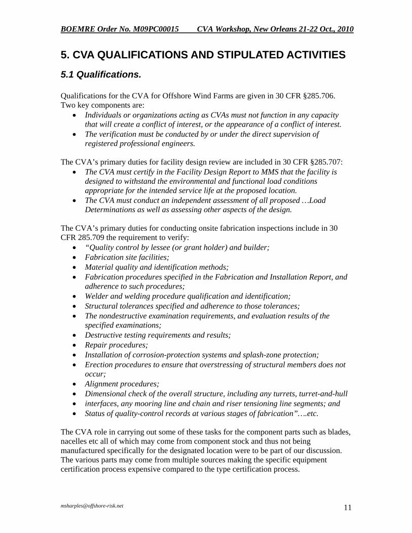
Qualifications for the CVA for Offshore Wind Farms are given in 30 CFR §285.706. Two key components are: • Individuals or organizations acting as CVAs must not function in any capacity
that will create a conflict of interest, or the appearance of a conflict of interest. • The verification must be conducted by or under the direct supervision of
registered professional engineers.
The CVA’s primary duties for facility design review are included in 30 CFR §285.707: • The CVA must certify in the Facility Design Report to MMS that the facility is
designed to withstand the environmental and functional load conditions appropriate for the intended service life at the proposed location.
• The CVA must conduct an independent assessment of all proposed …Load Determinations as well as assessing other aspects of the design.
The CVA’s primary duties for conducting onsite fabrication inspections include in 30 CFR 285.709 the requirement to verify: • “Quality control by lessee (or grant holder) and builder; • Fabrication site facilities; • Material quality and identification methods; • Fabrication procedures specified in the Fabrication and Installation Report, and
adherence to such procedures; • Welder and welding procedure qualification and identification; • Structural tolerances specified and adherence to those tolerances; • The nondestructive examination requirements, and evaluation results of the
specified examinations; • Destructive testing requirements and results; • Repair procedures; • Installation of corrosion-protection systems and splash-zone protection; • Erection procedures to ensure that overstressing of structural members does not
occur; • Alignment procedures; • Dimensional check of the overall structure, including any turrets, turret-and-hull • interfaces, any mooring line and chain and riser tensioning line segments; and • Status of quality-control records at various stages of fabrication”….etc.
The CVA role in carrying out some of these tasks for the component parts such as blades, nacelles etc all of which may come from component stock and thus not being manufactured specifically for the designated location were to be part of our discussion. The various parts may come from multiple sources making the specific equipment certification process expensive compared to the type certification process.

BOEMRE Order No. M09PC00015 CVA Workshop, New Orleans 21-22 Oct., 2010
The IEC indicates that blade testing is of key importance to assuring that blades do not break off and cause injuries etc., yet there is no specifics in the CFRs about tests to be done or indeed if any are required. This like many other items in the CFR is provided with no specifics about how to certify and indeed in 30 CFR 285.708 it is left to the CVA (or project engineer) to “use good engineering judgment and practice in conducting and independent assessment of the fabrication and installation facilities”. We thus tried to define this in the workshop.
The CVA functions 30 CFR §285.710 include: verify, survey, witness, survey or check the following items during facility installation:
• Loadout and initial flotation activities; • Towing operations to the specified location, and review the towing records; • Launching and up righting activities; • Submergence activities; • Pile or anchor installations; • Installation of mooring and tethering systems; • Final deck and component installations; and • Installation at the approved location according to the Facility Design Report and
the Fabrication and Installation Report” etc.
It should be of note that although software is not mentioned nor the subsea cables, if the structural integrity of the towers depends on those, then it should be and was part of any discussion as to the extent of verification and surveillance.
5.2 Information on the CVA role in Offshore Wind Farms is stipulated in the Code of Federal Regulation (30 CFR §285).
§285.707 What are the CVA's primary duties for facility design review? If you are required to use a CVA: (a) The CVA must use good engineering judgment and practices in conducting an independent assessment of the design of the facility. The CVA must certify in the Facility Design Report to MMS that the facility is designed to withstand the environmental and functional load conditions appropriate for the intended service life at the proposed location. (b) The CVA must conduct an independent assessment of all proposed:
[1]. Planning criteria; [2]. Operational requirements; [3]. Environmental loading data; [4]. Load determinations; [5]. Stress analyses; [6]. Material designations; [7]. Soil and foundation conditions; [8]. Safety factors; and [9]. Other pertinent parameters of the proposed design.

BOEMRE Order No. M09PC00015 CVA Workshop, New Orleans 21-22 Oct., 2010
(c) For any floating facility, the CVA must ensure that any requirements of the U.S. Coast Guard for structural integrity and stability (e.g., verification of center of gravity), have been met. The CVA must also consider:
[1]. Foundations, foundation pilings and templates, and anchoring systems; and [2]. Mooring or tethering systems.
§285.708 What are the CVA's or project engineer’s primary duties for fabrication and installation review? (a) The CVA or project engineer must do all of the following:
[1]. Use good engineering judgment and practice in conducting an independent assessment of the fabrication and installation activities;
[2]. Monitor the fabrication and installation of the facility as required by paragraph (b) of this section;
[3]. Make periodic onsite inspections while fabrication is in progress and verify the items required by § 285.709;
[4]. Make periodic onsite inspections while installation is in progress and satisfy the requirements of § 295.7 10; and
[5]. Certify in a report that project components are fabricated and installed in accordance with accepted engineering practices; your approved COP, SAP, or GAP (as applicable); and the Fabrication and Installation Report.
i.The report must also identify the location of all records pertaining to fabrication and installation, as required in § 285.7 14(c); and
ii.You may commence commercial operations or other approved activities 30 days after MMS receives that certification report, unless MMS notifies you within that time period of its objections to the certification report.
(b) To comply with paragraph (a)(5) of this section, the CVA or project engineer must monitor the fabrication and installation of the facility to ensure that it has been built and installed according to the Facility Design Report and Fabrication and Installation Report.
[1]. If the CVA or project engineer finds that fabrication and installation procedures have been changed or design specifications have been modified, the CVA or project engineer must inform you; and
[2]. If you accept the modifications, then you must also inform MMS.
§ 285.709 When conducting onsite fabrication inspections, what must the CVA or project engineer verify? (a) To comply with § 285.708(a)(3), the CVA or project engineer must make periodic onsite inspections while fabrication is in progress and must verify the following fabrication items, as appropriate:
[1]. Quality control by lessee (or grant holder) and builder; [2]. Fabrication site facilities; [3]. Material quality and identification methods; [4]. Fabrication procedures specified in the Fabrication and Installation Report, and
adherence to such procedures; [5]. Welder and welding procedure qualification and identification; [6]. Structural tolerances specified, and adherence to those tolerances; [7]. Nondestructive examination requirements and evaluation results of the specified
examinations; [8]. Destructive testing requirements and results;

BOEMRE Order No. M09PC00015 CVA Workshop, New Orleans 21-22 Oct., 2010
[9]. Repair procedures; [10]. Installation of corrosion-protection systems and splash-zone protection; [11]. Erection procedures to ensure that overstressing of structural members does
not occur; [12]. Alignment procedures; [13]. Dimensional check of the overall structure, including any turrets, turret-and-hull
interfaces, any mooring line and chain and riser tensioning line segments; and [14]. Status of quality-control records at various stages of fabrication.
(b) For any floating facilities, the CVA or project engineer must ensure that any requirements of the U.S. Coast Guard for structural integrity and stability (e.g., verification of center of gravity) have been met. The CVA or project engineer must also consider:
[1]. Foundations, foundation pilings and templates, and anchoring systems; and [2]. Mooring or tethering systems.
§ 285.710 When conducting onsite installation inspections, what must the CVA or project engineer do? To comply with § 285.708(a)(4), the CVA or project engineer must make periodic onsite inspections while installation is in progress and must, as appropriate, verify, witness, survey, or check, the installation items required by this section. (a) The CVA or project engineer must verify, as appropriate, all of the following:
[1]. Loadout and initial flotation procedures; [2]. Towing operation procedures to the specified location, and review the towing
records; [3]. Launching and uprighting activities; [4]. Submergence activities; [5]. Pile or anchor installations; [6]. Installation of mooring and tethering systems; [7]. Final deck and component installations; and [8]. Installation at the approved location according to the Facility Design Report and
the Fabrication and Installation Report. (b) For a fixed or floating facility, the CVA or project engineer must verify that proper procedures were used during the following:
[1]. The loadout of the jacket, decks, piles, or structures from each fabrication site; and
[2]. The actual installation of the facility or major modification and the related installation activities.
(c) For a floating facility, the CVA or project engineer must verify that proper procedures were used during the following:
[1]. The loadout of the facility; [2]. The installation of foundation pilings and templates, and anchoring systems;
and [3]. The installation of the mooring and tethering systems.
(d) The CVA or project engineer must conduct an onsite survey of the facility after transportation to the approved location. (e) The CVA or project engineer must spot-check the equipment, procedures, and recordkeeping as necessary to determine compliance with the applicable documents incorporated by reference and the regulations under this part.

BOEMRE Order No. M09PC00015 CVA Workshop, New Orleans 21-22 Oct., 2010
5.3 CVA for Oil and Gas Structures –from 30 CFR §250.909 – 918. For comparison and as background the following information summarizes the requirements for certain oil and gas equipment. Design CVA: Conduct an independent assessment:
(i) Planning criteria; (ii) Operational requirements; (iii) Environmental loading data; (iv) Load determinations; (v) Stress analyses; (vi) Material designations; (vii) Soil and foundation conditions; (viii) Safety factors; and (ix) Other pertinent parameters of the proposed design.
Fabrication CVA: Make periodic onsite inspections while fabrication is in progress and must verify the following fabrication items, as appropriate: (i) Quality control by lessee and builder; (ii) Fabrication site facilities; (iii) Material quality and identification methods;
(iv) Fabrication procedures specified in the approved plan, and adherence to such procedures; (v) Welder and welding procedure qualification and identification;
(vi) Structural tolerances specified and adherence to those tolerances; (vii) The nondestructive examination requirements, and evaluation results of the specified examinations;
(viii) Destructive testing requirements and results; (ix) Repair procedures;
(x) Installation of corrosion- protection systems and splash-zone protection; (xi) Erection procedures to ensure that overstressing of structural members does not occur;
(xii) Alignment procedures; (xiii) Dimensional check of the overall structure, including any turrets, turret-and-hull interfaces, any mooring line and chain and riser tensioning line segments; and
(xiv) Status of quality-control records at various stages of fabrication. Primary duties of the CVA during the installation phase include the following: Verify, as appropriate:
(i) Loadout and initial flotation operations; (ii) Towing operations to the specified location, and review the towing records; (iii) Launching and uprighting operations; (iv) Submergence operations; (v) Pile or anchor installations; (vi) Installation of mooring and tethering systems; (vii) Final deck and component installations; and

BOEMRE Order No. M09PC00015 CVA Workshop, New Orleans 21-22 Oct., 2010
(viii) Installation at the approved location according to the approved design and the installation plan.
Witness
(i) The loadout of the jacket, decks, piles, or structures from each fabrication site; (ii) The actual installation of the platform or major modification and the related installation activities.
Conduct an onsite survey of the platform after transportation to the approved location. Spot-check as necessary to determine compliance with the applicable document listed as standards (references are noted in the CFR) for:
(i) Equipment; (ii) Procedures; and (iii) Recordkeeping.
*Please note when referring to CVA that “he” above may also be “she”. Further more detailed discussion can be found on this subject at http://www..gov/tarprojects/633.htm Report AE.
6. RESULTS The results of the workshop are the Worksheets showing the generally agreed opinion of the participants (not always unanimous) as to the general approach recommended for the CVA activities. These are broken down to two appendices. The Recommendations from the workshop are given in Appendix L. The participants are listed in Appendix M.
Appendix J Surveillance CVA Activities lays out the list of major components making up the wind farm. The definitions of those items are given in the cover sheet to Appendix J. Two different options were proposed to satisfy the fabrication CVA requirement: one where the equipment arrived at site with a Type Certification and one where it did not. Separate proposed activities were listed for Loadout-Transportation-Lifting, for Installation, and for Commissioning. (This may vary somewhat as a result of the owner’s proposal to BOEMRE in the Facility Design Report). The proposed CVA Activity notes whether there is no activity (-NA-) because it is not a CVA duty. Items and explanations are added as appropriate.
Appendix K Design CVA Worksheet lays out the Items of Proposed Design Information, followed by the Proposed CVA activity in Design. (This may vary somewhat as a result of the owner’s proposal to BOEMRE in the Facility Design Report). The proposed CVA Activity notes whether there is no activity because it is not a CVA duty, and if it is a CVA duty notes the activity.

BOEMRE Order No. M09PC00015 CVA Workshop, New Orleans 21-22 Oct., 2010
APPENDIX A: AGENDA
BOEMRE OFFSHORE WIND CVA WORKSHOP
AGENDA 10/19/10
Thursday, October 21
7:00 – 8:00 a.m. Registration - Coffee and Croissants provided
MORNING SESSION
8:00 – 8:15 a.m. Welcome: Introductions – (round the room) – Name, & Affiliation.
Overview of Desired Workshop Outcome-- Briefing by John Cushing & Lori Medley
8:15 – 9:00 a.m.
“CVA Expected Activities- Surveillance and Design” - Malcolm Sharples, Offshore Risk & Technology Consulting, Inc.
9:00 – 9:45 a.m. “GL Thoughts on CVA Activities and Surveillance for Offshore Wind Farms”
C. Todd Wynn - (Confirmed but title not confirmed) 9:45- 10:30 “DNV Thoughts on CVA Process for Offshore Wind Farm Design Activities” Kim Mørk - DNV Energy 10:30 – 10:45 a.m.
Coffee Break 10:45- 11:30 a.m.
“BV Thoughts on CVA Process for Offshore Wind Farm Fabrication” Kevin Wedman BV (Title to be confirmed)

BOEMRE Order No. M09PC00015 CVA Workshop, New Orleans 21-22 Oct., 2010
11:30 – 12:15 noon.
“ABS Thoughts on CVA Process for Offshore Wind Farm SurveillanceTransportation, & Installation” Luiz Feijo (Title not confirmed)
12:15-1:00 Lunch
1:00 – 2:00 pm
KEYNOTE PRESENTATION
“Certification of the complete project: How to deal with the uncertainties and with site specific turbine certification” – Jaap Olthoff – Olthoff Wind Group BV, The Netherlands.
WORK SESSION 1: 2:00-2:15 ”CVA Activities with Transformer Platform- A Quick Review”
(same as oil and gas CVA) – Partha Ganguly – Millennium Technical Consultants Inc.
2:15- 4:30. Surveillance during Fabrication, Loadout/Transportation/Lifting and Installation/Commissioning Phases – Wind Turbine Structures etc.
Facilitator: Kent Dangtran, DOTC LLC Participation: All Materials: Table of Proposed Surveillance Activities to be Commented on/ Changed by discussion.
3:00 pm – 3:30 pm Refreshment Break
4:30 – 5:15 p.m. PARKING LOT ISSUES Part 1:
Facilitator: Malcolm Sharples Participation: All

BOEMRE Order No. M09PC00015 CVA Workshop, New Orleans 21-22 Oct., 2010
Friday, October 22
7:00 – 8:00 a.m.- Coffee & Croissants
8:00 – 9:30 a.m. WORK SESSION 2: Design CVA Review Activities.
Facilitator: Malcolm Sharples Participation: All Materials: Table of Proposed CVA Design Review Activities to be Commented on/ Changed by discussion.
9:30 – 10:00 a.m. Coffee Break
10:00 – 11:45 a.m.
WORK SESSION 3: Recommendations to BOEMRE from Workshop Discussions.
Parking Lot Session – Part 2
HAZID Sessions – Load Cases – How, What, When CVA Role in Return Period etc. Construction/ Installation Activities CVA Role in Return Period etc. Design CVA Role – in HAZID BOEMRE Role – in HAZID
Qualifications of CVA – -Qualifications of “Type Certifier” / Proj. Engr. as CVA
Other Items
Facilitators: Malcolm Sharples/Kent Dangtran Participation: All 12:00 – 12:45 p.m. Lunch Break 12:45 p.m. - 2 p.m. General Discussion plus Questions and Answers. 2:00 p.m. ADJOURN 2:00 – 3:30 Wrap up of Notes etc. by sponsors and facilitators prior to departing.

BOEMRE Order No. M09PC00015 CVA Workshop, New Orleans 21-22 Oct., 2010
APPENDIX B: BOEMRE Background Info and Workshop Goals
by John Cushing, BOEMRE

1
TAR Project #633TAR Project #633 CVA WorkshopCVA Workshop
John CushingJohn Cushing
BOEMREBOEMRE
21 October 201021 October 2010
Bureau of Ocean Energy Management, Regulation,
and Enforcement (BOEMRE)
30 CFR 285 – “Renewable Energy & Alternate Uses of Existing Facilities on the OCS”
¾ Subpart A – General Provisions ¾ Subpart B – Issuance of Leases ¾ Subpart C – Rights of Way Grants/Easements ¾ Subpart D – Lease & Grant Administration ¾ Subpart E – Payments & Financial Assurance ¾ Subpart F – Plans & Information Requirements ¾ Subpart G – Facility Design, Fabrication, & Installation (incl. CVA requirements) ¾ Subpart H – Env. & Safety Management, Inspections, & Facility Assessments
BOEMRE requirements for Offshore Wind Projects
Leasing & Payments
Plans & Inspections
Bureau of Ocean Energy Management, Regulation,
and Enforcement (BOEMRE)
30 CFR 285 – “Renewable Energy & Alternate Uses of Existing Facilities on the OCS”
¾ No specific design requirements for: 9 Met towers, 9 Wind turbines, 9 Transformer platforms, 9 Subsea cables.
¾ No specific requirements for equipment or workplace safety & health.
¾ BOEMRE intends to use “design basis” approach for review/approval of offshore wind projects.
¾ BOEMRE regs include CVA requirements in Subpart G (30 CFR 285.705 to .712).
BOEMRE requirements for Offshore Wind Projects
Bureau of Ocean Energy Management, Regulation,
and Enforcement (BOEMRE)
BOEMRE requirements for Offshore Wind Projects
Comprehensive regulatory process,
per 30 CFR 285
Phase 1
Phase 2
Phase 3
Bureau of Ocean Energy Management, Regulation,
and Enforcement (BOEMRE)
BOEMRE requirements for Offshore Wind Projects
There is also a “Non-Competitive” process, which is more streamlined
Bureau of Ocean Energy Management, Regulation,
and Enforcement (BOEMRE)
BOEMRE requirements for Offshore Wind Projects
Certified Verification Agent (CVA): ¾ CVAs are independent companies employing Professional Engineers
with appropriate quals & experience to conduct third-party reviews.
¾ CVAs have been used in review/approval process for offshore oil & gas structures since the 1980s.
¾ CVAs provide independent third-party review of: 9 Design 9 Fabrication 9 Installation
¾ CVAs should not have been involved in any original design work (working for developer) if they are to perform any design, fabrication, or installation CVA duties (oversight of developer).
¾ CVA is nominated/retained by developer, but performs reviews for and reports directly to MMS.
Bureau of Ocean Energy Management, Regulation,
and Enforcement (BOEMRE)
BOEMRE requirements for Offshore Wind Projects
Bureau of Ocean Energy Management, Regulation,
and Enforcement (BOEMRE)
BOEMRE requirements for Offshore Wind Projects
Bureau of Ocean Energy Management, Regulation,
and Enforcement (BOEMRE)
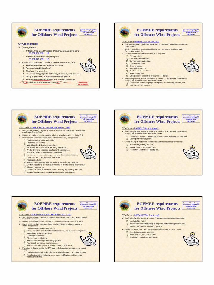
CVA (continued): ¾ CVA regulations…
9 Offshore Oil & Gas Structures (Platform Verification Program): 30 CFR 250.909 - .918
9 Offshore Renewable Energy Projects: 30 CFR 285.705 - .712
¾ “Qualification statement” must be submitted to nominate CVA: 1. Previous experience with similar structures 2. Technical capabilities of staff 3. Size/type of organization 4. Availability of appropriate technology (hardware, software, etc.) 5. Ability to perform CVA functions for specific project 6. Previous experience with MMS requirements/procedures
CVA Duties – DESIGN (30 CFR 285.707): ¾ Use good engineering judgment & practices to conduct an independent assessment
of the design.
¾ Certify that facility is designed to withstand environmental & functional loads for intended service life.
¾ Conduct an independent assessment of all proposed: 1) Planning criteria, 2) Operational requirements, 3) Environmental loading data, 4) Load determinations, 5) Stress analysis, 6) Material designations, 7) Soil & foundation conditions, 8) Safety factors, and
9) Other pertinent parameters of the proposed design. ¾ For floating facilities, the CVA must ensure any USCG requirements for structural
integrity and stability are met, and must consider: 1) Foundations, foundation pilings & templates, and anchoring systems, and 2) Mooring or tethering systems.
7. Level of work to be performed by CVA To address at this workshop!
BOEMRE requirements for Offshore Wind Projects
Bureau of Ocean Energy Management, Regulation,
and Enforcement (BOEMRE)
CVA Duties – FABRICATION (30 CFR 285.708 and .709): ¾ Use good engineering judgment & practice to conduct an independent assessment
of the fabrication activities. ¾ Monitor fabrication to ensure structure is built in accordance with the FDR & FIR. ¾ Make periodic onsite inspections during fabrication to verify, as applicable:
1) Quality control by lessee and builder, 2) Fabrication site facilities, 3) Material quality & identification methods, 4) Fabrication procedures in FIR are being adhered to, 5) Welder & welding procedure qualification & identification, 6) Structural tolerances specified and adhered to, 7) Nondestructive examination requirements and evaluation of results, 8) Destructive testing requirements and results, 9) Repair procedures, 10) Installation of corrosion-protection systems & splash-zone protection, 11) Erection procedures to ensure overstressing of structural mbrs doesn’t occur, 12) Alignment procedures, 13) Dimensional check of overall structures, including any mooring lines, and 14) Status of quality control records at various stages of fabrication.
CVA Duties – FABRICATION (continued): ¾ For floating facilities, the CVA must ensure any USCG requirements for structural
integrity and stability are met, and must consider: 1) Foundations, foundation pilings and templates, and anchoring systems, and 2) Mooring or tethering systems.
¾ Certify in a report that project components are fabricated in accordance with: 1) Accepted engineering practices; 2) Approved COP, SAP, or GAP; and 3) Fabrication & Installation Report (FIR).
BOEMRE requirements for Offshore Wind Projects
Bureau of Ocean Energy Management, Regulation,
and Enforcement (BOEMRE)
BOEMRE requirements
for Offshore Wind Projects Bureau of Ocean Energy Management, Regulation,
and Enforcement (BOEMRE)
CVA Duties – INSTALLATION (30 CFR 285.708 and .710): ¾ Use good engineering judgment & practice to conduct an independent assessment of
the installation activities. ¾ Monitor installation to ensure structure is installed in accordance with FDR & FIR. ¾ Make periodic onsite inspections during installation to verify, witness, survey, or
check, as applicable: 1) Loadout & initial flotation procedures, 2) Towing operation procedures to specified location, and review of towing record, 3) Launching & uprighting activities, 4) Submergence activities, 5) Pile or anchor installations, 6) Installation of mooring and tethering systems, 7) Final deck & component installations, and
8) Installation at the approved location according to FDR & FIR
¾ For a fixed or floating facility, the CVA must verify that proper procedures were usedduring:
1) Loadout of the jacket, decks, piles, or structures from each fabrication site, and 2) Actual installation of the facility or any major modifications and the related
installation activities.
CVA Duties – INSTALLATION (continued): ¾ For floating facilities, the CVA must verify proper procedures were used during:
1) Loadout of the facility, 2) Installation of foundation pilings & templates, and anchoring systems, and 3) Installation of mooring & tethering systems.
¾ Certify in a report that project components are installed in accordance with: 1) Accepted engineering practices; 2) Approved COP, SAP, or GAP; and 3) Fabrication & Installation Report (FIR).
BOEMRE requirements for Offshore Wind Projects
Bureau of Ocean Energy Management, Regulation,
and Enforcement (BOEMRE)
2

3
General Thoughts
Risks: ¾ Need to take conservative approach, because many unknowns:
9 Environmental loadings (especially hurricanes) are big “wild card.”
9 Subsea soil conditions & scour not well known in “frontier areas.”
¾ Need to consider the impact of catastrophic failures, especially when a design flawcould lead to the failure of many structures:
9 Human Risk (unmanned structures) – Low
9 Environmental Risk (minimal oil storage) – Low
9 Power Supply Risk (disruption of electricity to grid) – Medium?
9 Industry Risk (credibility for growth of new industry) – High?
Standards: ¾ Preference is to use U.S. standards whenever possible.
¾ European or International standards should be considered when there are shortcomings or gaps.
Bureau of Ocean Energy Management, Regulation,
and Enforcement (BOEMRE)
General Concept Bureau of Ocean Energy Management, Regulation,
and Enforcement (BOEMRE)
U.S. land-based wind experience
U.S. offshore oil & gas experience
European offshore wind experience
U.S. offshore wind program
Projects relating to CVA role
Marine Board: ¾ Conducted a CVA Workshop for BOEMRE in March 2010. ¾ Conducting a Follow-on Study to be completed by Feb 2011. ¾Workshop & study to provide general feedback to BOEMRE regarding:
9 CVA qualifications 9 CVA role 9 Standards for U.S. offshore wind farms
AWEA: ¾ AWEA’s “Large Wind Turbine Standards ‘Roadmapping’ Workgroup” has met
3 times (Oct 2009, May 2010, and Oct 2010).
¾ Goal is to complete draft guidance by Dec 2010, and final guidance by Dec 2011.
¾ Focus: Standards for U.S. wind turbines – both land-based & offshore.
TAR Project #633: ¾ Includes this workshop to clarify CVA role.
Bureau of Ocean Energy Management, Regulation,
and Enforcement (BOEMRE)
Questions?

BOEMRE Order No. M09PC00015 CVA Workshop, New Orleans 21-22 Oct., 2010
APPENDIX C: CVA Expected Activities: Surveillance and Design by Malcolm Sharples, Offshore Risk & Technology Consulting Inc,

1
Offshore Wind Workshop CVA Expected Activities: Surveillance and Design
on the OCS
Offshore Risk & Technology Inc.
Malcolm Sharples 1
Welcome to the Offshore Wind Workshop – Many of the functions that I have been to on Offshore Wind have been entertaining, which I hope this one is too….however, our main purpose here is to WORK, THINK, DISCUSS and COME TO a set of RECOMMENDATIONS for the BOEMRE on the role of the Certified Verification Agent on the OCS. We all, in this room at least, are all probably on board with the fact that wind power will be part of the electricity mix going forward for the United States Global Growth seems to be inevitable.

2
2
Growth Appears Inevitable
In terms of wind power, USA has the highest installed capacity and it growth each year is amazing. For offshore wind the U.K. now leads ahead of Denmark who installed the first wind turbines offshore. There have been a lot of lessons learned thanks to the research carried out in Denmark and in Europe. The amount of funds spent in research is far more than has been or is being spent in the United States. The Europeans have been working on this technology for decades. It will not be easy to play catch up. Our issue here is to help define the roadmap to the regulatory process for offshore wind farms.

3
3 Ref: World Wind Energy Association wwec2010.com
Growth Appears Inevitable
The table presented for both the current capacity for offshore wind and rate of growth is given based on the World Wind Energy Association data. We are also aware that China is looking at offshore wind, around Bohai Bay, so they will soon be an important force in this market.

4
This is NOT your O&G CVA! • Geographically Concentrated Risk
• Structural Integrity depends on – Tower Strength – Battery Backup for Yaw Alignment – Control Systems – Communications – Software – Fatigue Resistance of Soil – Very little redundancy 4
The first thing to stress is that the CVA process is not like oil and gas CVA process. Oil and Gas platforms are relatively well spaced in the Gulf of Mexico. For structures in a wind farm it is a geographically concentrated risk. All the eggs in one basket. Worse yet, since the likely location of wind farms is where there is a concentration of population, up the east coast of the US, with hurricanes that often track up the east coast it is likely that multiple wind farms are likely to be affected by one hurricane event. Another characteristic of the offshore wind farms, according to the loading cases in the IEC Code, the structural integrity depends upon the turbine’s ability to rotate into the wind within a few degrees, or the tower strength may be compromised. In the IEC Code, appropriate for Europe, the nacelle can yaw with the help of a 6 hr battery to operate the yaw system, and that appears sufficient for their purposes. For US application in hurricane areas, there are frequent wind direction shifts during hurricanes, and it is unlikely that a 6 hr battery life will be sufficient to sustain the power to orient the nacelle into the wind during the entire event. The consequences are that the tower is overloaded at anything beyond the design value of a 1-year return period storm (according to the IEC Code load cases). The probability of multiple tower failures is thus of concern. Since Structural Integrity depends on power it means the CVA process may need to check not only Tower Strength but also: the Battery Backup system; the Yaw assembly; the Control systems that return the blades to a parked position; the Software that operates the Control System; the communications that relay signals between the control computers and the mechanical mechanisms, as well as just what might be called the strictly “structural calculations” which would be the only concern with a typical oil and gas platform. The safety factors on the fatigue resistance of the soil may play an important role here as well. In short there is little or no redundancy in the offshore wind farm structures – meaning every component could be a contributor to structural failure.

5
5
2 Design Approaches APPROACH: OMNIDIRECTIONAL
Design not sensitive to the changes in the wind direction API RP2A
APPROACH: STANDARD Design, which is supported by back-up power supply securing power for the yawing systems
IEC Code Solution: 6-hour Battery
The photo on the top right was from an incident in 1999 in Japan. The reference indicates that there was loss of yaw angle and then loss of the structure. The photo on the left is from 2003 Typhoon Maemi where 7 turbine structures were lost: 3 of which were towers. Loss of power pre-ceded the failures. Admittedly the wind speeds were past the values to which the structures were designed.
In Japan - 2005 for 100 cases (out of 900 reporting) - 38 were attributed to storm and lighting; 25 to faults in construction and manufacture; 4 poor management; 33 unknown.
The other structural failures (bottom 2 photos on the right) were failures in Europe, and there is no reference in the literature as to direct cause.
There are 2 approaches that engineers could take to design of offshore wind structures. One would be to design for an omni-directional approach of the wind with the turbine in parked position or even not in parked position. In that case the role of the CVA would be easy: they would follow API RP2A. Only the Working Stress Design (WSD) version of this is incorporated in the regulations at the moment. The LRFD version could be updated and included or the ISO effort ongoing for fixed platforms could be used. The standard approach appears to be to design using the IEC loadcases which stipulates that the design is supported by a backup power supply securing power for the yaw systems. The IEC recommended duration of the event provided for is 6 hours which may not be adequate for USA application particularly in hurricane areas.

6
Experience from India!
6
Tropical Cyclone 03/A destroyed
129 or 40% of the 315 wind turbines
A critical factor in the failures in India is that the grid alsofailed…….. Wind turbine manufacturers would be well advised to check that this load case has been included in their design calculations. (prior to IEC Code)
The experience from India – probably typical of the concern for the US hurricane events is the potential loss of multiple towers in multiple fields. In India in 1998 40% of the wind turbines were lost in 1 cyclone event. A paper chronicling the event referred to the issue of loss of power being a “critical factor”. While this was over 12 years ago, the load cases that are noted in the IEC code have not sufficiently addressed this risk. Papers by Tarp Johannsen at the Offshore Technology Conference and elsewhere refer to the need for higher load factors in typhoon and hurricane areas.

7
Mission of BOEMRE
“Encourage orderly, safe and environmentally responsible development”
• When is that fulfilled? – Blade falls off? Gearbox fails? – Many towers fail in one field? – Floating wind farms break moorings and
“helter-skelter”? – Tsunami comes up Cook Inlet (if built)?
Barometer: Somewhere in between Maintenance & the Press? 7
The Mission of the BOEMRE is noted. Our discussions will focus on when that mission is fulfilled. If the Gearbox fails, or a blade is damaged for falls off: is that considered a failure of the CVA process. That is probably more of a maintenance issue – if a ship’s gearbox fails, is that a catastrophic event in the eyes of the regulator or those judging the effectiveness of the regulator? In this forum it is perhaps useful to contemplate the worst possible events and seek to put efforts and resources of the CVA process to prevent those cases: perhaps something that falls between a maintenance item and something that would attract the press to report the event as a casualty. We are after all looking at this as a social risk, not one involving the usual loss of life risk, or pollution risk. Such events may be many towers failing in one field, or floating wind farm structures breaking their moorings and drifting onto the beach possibly damaging other structures on the way. Perhaps if these offshore wind towers appear in Cook Inlet it should ensure that the design has taken account of the possibility of extra high tidal fluctuations and the possibility of Tsunamis.

8
CFR Guidance to Design CVA 285.707
• Independent Assessment of Design – Not about the Safety Management system
• CVA must certify in the Facility Design Report: that it withstands “the environmental
and functional loads appropriate for the intended service life”
• Soil and Foundations • Planning Criteria • Safety Factors • Operational Req’ts
and • Environmental Loads Ensure USCG conditions are met for • Load Determinations Floating Systems: • Stress analysis • Stability • Material Designations • Foundations/ Anchorings (285.701) 8
IEC Covers Load NOT Resistance
This slide reflects the provisions for the task of the CVA as outlined in 30 CFR 285.707. It may prove difficult for commercial organizations that are likely to act as CVAs to be able to certify for the intended service life. The certification in oil and gas is a one-time event prior to startup. Certifying for a lifetime may be a potential liability that certifiers are unlikely to wish to take on. The oil and gas equivalent CVA requirement is to “ensure” rather than “certify” the structure withstands the loads for the intended service life (30 CFR 250.916. It is recommended that this wording be discussed in detail.

9
CFR Guidance to Fab./Install CVA 285.708
• Independently Assess Fab. /Install activities • “Monitor” to ensure fabricated & installed per
Facility Design Report • Modifications approved by CVA/BOEMRE • Periodic on-site inspections • Identify all “records” on fab. /install
• QA Records • As-built of in-field and shore cables? • As-Built Dwgs ? • Pile blows if piled ? • Material Certs • Welding a nd NDT records? • Management of Change ? • etc. • Risk Register?
9
The guidance offered in 30 CFR 285.708 is very similar to the requirements in oil and gas. The issue for windfarms is that the industry deals with multiple critical components whereas for oil and gas platforms the issue is much simpler. The component sources for oil and gas are usually 1 or 2 since only the steel structure needs checking and these are assembled on shore in 1 or 2 locations, whereas for wind turbines components arrive from multiple sources around the world and the majority can individually trigger a structural failure. It is suggested that to the extent possible the CVA process should rely upon Type Certification according to the IEC code, and that the CVA process commence only at the Marshalling yard (shore base prior to components being transported to the installation site).

10
CFR: Fabrication CVA to Verify 285.709
• Quality control by lessee • Fabrication Site facilities • Material Quality and identification • Fabrication Procedures • Welder & Welding Qual. and Identification • Prescribed Tolerances • NDT; Testing to destruction e.g. grout • Repair procedures • Splash Zone protection; corrosion- protection system • Erection to ensure no overstressing • Alignment • Dimensional Check • Mooring equipment check
10
The slide lists the details reported as required by 30 CFR 285.709.

11
CFR: Installation CVA to Verify 285.710
• Loadout and floatation ? – need discussion • Towing ops. procedures and review tow records – need
discussion • Pile & anchor installation • Installation of mooring and tethering – interpreted as
permanent moored equipment only • Final deck and Component installation • Installation at approved location • Spot check equipment procedures, and recordkeeping to
determine compliance with the applicable documents incorporated by reference and regulations.
The slide lists the details reported as required by 30 CFR 285.710.
11

12
12
Provided by IEC Type Certificate Fabrication + Transport &
Install Plans/Limits
QMS
Design Assessment
Initial Production Test
Type Certificate
Relying upon Type Certification as described in the IEC Code would form a good basis for the CVA process. The Type Certificate is issued by an accredited agency. In the US the accreditation agency would be ANSI and at this point in time ANSI have no program to accredit bodies in offshore wind farms as is done in Europe. Barring that, it would fall on BOEMRE to approve the Certifier as it is unlikely that the CVA would wish to take on the responsibility of ensuring that the certifier is qualified. One easy solution for the time being would be to accept a European accreditation agency qualified certifier.

13
13
Type Cert from IEC 61400-22
Details included in the IEC Certificate are described in Annex B to IEC 61400-22 on Certification. There may be items that need adding to this document such as life of the battery, rates of deceleration imposed by the brakes and breaking system and perhaps other points to be discussed in detail.

14
Commissioning for CVA req’ts
• Functioning of Emergency Shutdown Equipment • Fail safe of Protection System incl. Triggering of
Brakes by every (req’d) Operating Condition • Functioning of Yaw System • Behavior at loss of Load • Functioning of Automatic operation • Check Logic of Control System • Check logic of Condition Monitoring • Ensure documentation available as req’d.
14
While commissioning is not discussed in detail in the CFRs this slide suggests some issues to be addressed for some of the systems that ensure structural integrity under extreme circumstances.

15
15
CVA Modifications/ Decommissioing
• Out there – but our Primary Focus Today
While there is provision for the CVA to attend major modifications and decommissioning, our main focus of the workshop is the Surveillance and Design activites of the CVA.

16
16
Turbine Classes for Select US Locations
At the AWEA conference just held in Atlantic City. Susan Stewart of Penn State presented an interesting table showing the IEC Wind classes that would qualify for use offshore various ports in the US, color coded for acceptability. There are many locations that the wind speed is higher than the IEC standard wind turbine classes and thus Special “S” class turbines will be required.
17
17
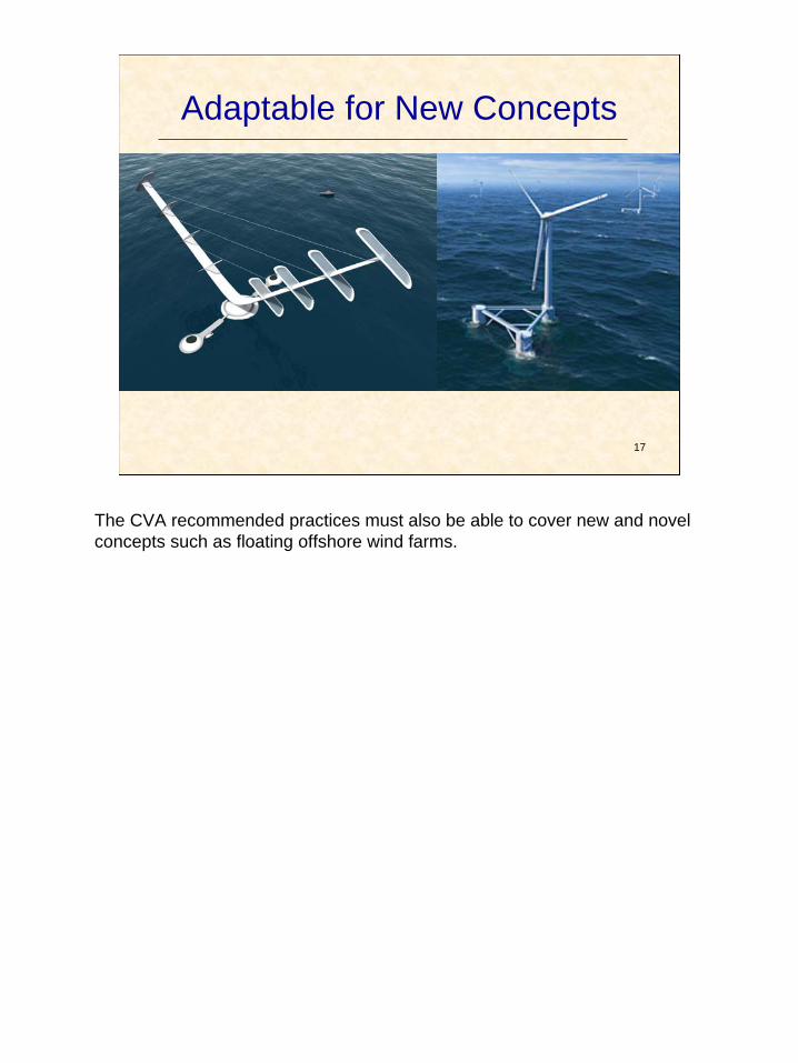
Adaptable for New Concepts
The CVA recommended practices must also be able to cover new and novel concepts such as floating offshore wind farms.

18
HAZID: Determine Site-Specific Load Cases
1. Parked with Fault – 1- year return period storm? – Battery Life ? (Japanese Guidelines?)
2. Other Conditions for Load Cases – Maximum size service vessel hitting at 0.5 m/sec? – Construction: if manufacturer’s limiting condition lasts more
than a week consider a 1-year return storm. (ma x wind, associated wave; max wave, associated wind).
(At this stage there may be no power, no control system)
Attendance of CVA if possible: Understanding of the Facility Design Report proposed Criteria
No Agreement at HAZID for Design CVA
18
One of the recommendations is that there be a HAZID reported within the Facility Design Report and that the nominated CVA also be present at this HAZID. This is to ensure all the stakeholders are on the same page as far as the loadings and the implications of the loadings. For example: deciding whether the Facility Design Report will include a limitation of a 1-year return period storm if the power fails. In Japan they have been concerned about typhoons and have elected to extend the battery life depending on the results of a Monte Carlo simulation. The results of the new Japanese requirements are not yet published. Deciding on the likely size of service vessel to design for should also be subject to an agreement between the stakeholders. It is also suggested that the criteria for temporary conditions during installation be decided at this stage. For oil and gas platform work, it is generally recognized that a 10-year storm is used for temporary conditions during assembly and installation (this is, of course, usually further offshore than for wind farms). The IEC Code recommends the temporary design condition be a 1-year storm. This is a disconnect that should be considered by the stakeholders prior to submission to BOEMRE as part of the Facility Design Report.

19
Work Sessions: 2
• For Each Component in the Wind Turbine – What to do (Surveillance/ Calculations) for
CVA for 3 stages: • Fabrication • Transportation/ Loadout/ Lifting (>marshalling yd) • Installation • Commissioning
• For Each Potential Loading Event – What checks to be carried out by CVA
19
Following the introductory talks we will have 2 work sessions to decide on Surveillance and Design checks to be carried out by the CVA.

20
PARKING LOT ITEMS
• Whether Mechanical/Electrical Systems are included in CVA Activities
• Accreditation of Type Certifiers • Criteria – Extremes for Tow/Installation • - Extremes for Design • ?
20
The Parking Lot Items will be accumulated in the workshop and discussed later. In order not to be diverted from our tasks we would ask the participants to accept, for the time being that mechanical and electical systems are included in the intent of the CVA process. The reason for putting this in the parking lot, is primarily because participants who are not as familiar with the workings of wind farm turbine structures have occupied a lot of time becoming educated on these points at the expense of other meetings’ time. Thus, we are proposing to put this in the parking lot. It can be discussed at length in the wrap up session, and for those who wish to discuss before my collegues and I will be available to discuss it during the breaks, lunch, and the Thursday evening. It is a legitimate point, but there is more to be accomplished than just the discussion of this one point. Another parking lot item we propose to discuss tomorrow is the accreditation issue of Type Certifiers that will be a long discussion. The return period for extremes of design (50 vs 100 year), and extremes for temporary conditions – will be another item to discuss in parking lot session later on.

21
21
Surveillance Activities Option 1 -Fabrication Check: (Type Cert.-accredited org.) - Ensure per Facility Design Report -Type Certification for specific mfct location (Check Certification paperwork to ensure no exclusions in certs)
Option 2 -Fabrication Check: (No Type Cert.) - Ensure per Facility Design Report. - Certified welder; Certified materials; Quality, Traceability, Weld Specs.; - Review of records, NDT and FAT as applicable (Check visually 10% -15%: ramp % up or down with experience) - Repair per Spec.
Loadout/Transporta tion & Lifting Check: - Ensure sign-off by Fabrication CVA - Attend first loadout/transport at marshalling area & offshore lift (10% -15% thereafter) Visual 10% -15% at marshalling area prior to & during offshore loadout. - Conduct first batch site arrival survey & lift arrangement; (Ramp % up or down with experience) - Inspect before installation. (Verify mfct. lifting arrangements match the site situation)
Installation Check: - Final fitup and dimensional control (mainly tower and transitional pieces) checks; - Attend/witness first Installation and subsequently 10-15%; ramping up or down as appropriate
(Welding Connection: 10% -15% Visual inspection;
ramp % up or down with experience)
(Bolting Connection - see below) - Review of NDT records. - Ensure no damages or repaired to spec. - Ensure Records are kept (e.g. pile driving, bolt torque, grouting records etc.)
Commissioning Check: Attend first and then 10% of Commissioning tests or as per discretion of CVA.
Finally. During the Work Sessions – the surveillance activities have been boxed into 2 categories for the Fabrication Check, 1 for Loadout/ Transportation/ Lifting, 1 for Installation and 1 for Commissioning. We have suggested these as a starting point. As we go through each component and test what this groups thinks is appropriate activity for the CVA these activities will be expanded, changed, the % surveillance changed etc. We just have put these up as a starting point.

22
22
CVA for Design Activities
Verify plausibility of anchor embedment/ capability for stationkeeping based on loads and soil type.
Soil data to determine Anchor Suitability
2
Consider effect (if any) on design Shallow Hazard Survey 2
Verify Plausibility. Penetration of Foundation 2
Verify Plausibility and extent/quality of soil information; precautions e.g. Scour
Site Specific Soil Data 2
Verify Plausibility including: Extremes, Scatter Diagrams, Breaking Waves, Temperatures, Marine Growth,etc.
Site Specific Metocean /Seismic etc. (wind, wave, current, waterlevel etc.) per NOAA or other standard equivalent if a TRS site; 50/100 year winter storm data; 100-year airgap.
1
Comments Proposed CVA Activity Items of Design Information #
Finally. During the Work Sessions – the surveillance activities have been boxed into 2 categories for the Fabrication Check, 1 for Loadout/ Transportation/ Lifting, 1 for Installation and 1 for Commissioning. We have suggested these as a starting point. As we go through each component and test what this groups thinks is appropriate activity for the CVA these activities will be expanded, changed, the % surveillance changed etc. We just have put these up as a starting point.

23
23
Questions?
Offshore Risk & Technology Inc. 506 Nottingham Oaks Tr. Suite 200, Houston, Texas 77079
Tel: 713 922 8170
Email: [email protected] or [email protected]

BOEMRE Order No. M09PC00015 CVA Workshop, New Orleans 21-22 Oct., 2010
APPENDIX D: Offshore Wind Energy Workshop, New Orleans
by C. Todd Wynn , Head of Offshore Wind, North America, GL Garrad Hassan

Dieser Platz ist für Ihr Bild vorgesehen
1. GL‘s History in Wind Energy
• 1977 First activities in Wind Energy
• 1980 Examination GROWIAN (3 MW; Ø=100m)
• 1984 Testfield Kaiser-Wilhelm-Koog
• 1986 1st Guideline (onshore)
• 1994 European Offshore Study
• 1995 1st Offshore Wind Guideline
• 2005 2nd Ed. Offshore Wind Guideline
• 2009 first german Offshore Wind Farm certified (alpha ventus)
Welcome to the world’s largest provider of technical advice and engineering consultancy services to the renewable energy market.
1. Who is GL Garrad Hassan
No. 6 No. 5
Germanischer Lloyd
Offshore Wind Energy Workshop, New Orleans
C. Todd Wynn , Head of Offshore Wind, North America, GL Garrad Hassan
No. 2
Content:
1. Who is Germanischer Lloyd (Renewables)
2. Rules & Guidelines, Type Certification Æ Project Certification
3. Reference projects
4. Example for an independent assessment (collission betweet ship and turbine)
1. Who is Germanischer Lloyd (Renewables)
No. 3
•
•
•
Long established, privately owned and profitable technical service provider • 7,000 employees • 235 offices • 80 countries
Maritime Services • leading ship classification society
to ensure the safety of life and property at sea
• technical consultancy for shipping and ship-building industries
Industrial Services • technical assurance and • engineering consulting for
energy and process industries
1. Germanischer Lloyd is a world-class technical service provider for the Maritime and Energy markets Germanischer Lloyd at a glance
No. 4

1. Geographical reach
700 renewables staff, in 35 locations, across 22 countries
Heerenveen Sint Maarten
Kaiser-Wilhelm-
Already the world’s biggest rotating machines
108 cycles
A modern commercial blade,
but not the first of its size.
Clipper is in the process of building a 71 m blade (150 ft rotor diameter) for their new 10 MW WTG!
Vancouver Beijing Ottawa Tokyo
Portland Shanghai San Diego Mumbai
Montreal Bangalore Peterborough Newcastle
Austin Melbourne Monterrey Wellington
Houston Porto Alegre
Koog
Bristol Dublin
Paris
Izmir
Copenhagen
Barcelona
Imola
HinnerupOldenburgHamburgPoland
Lisbon ZaragozaMadrid
Glasgow
Slough London
No. 7
Boeing 747 3.6 MW 2.3 MW
Source Siemens Wind Power
110m rotor
• Diameter, D = 110m • Area, A = π D2 / 4 • Density, ρ = 1.225 kg/m3
• Wind speed, V = 10 m/s • Mass per second = ρ A V = 116,000 kg
How much air passes through a rotor in one second? Lifetime
• A car operates continuously for about 9 months
• A wind turbine operates continuously for 20 years
One wind turbine life time = 25 VW Golf life times
How much air passes through a rotor in one second?
100 Golfs per sec
110m rotor
The largest blade, 61.5m, 5MW

i ii
i
No. 13
2. Rules & Guidelines, Type Certification Æ Project Certification
2. Certification of Wind Turbines
Certification of Windfarms, Windturbines and their components is state of the art and a must almost worldwide
No. 14
No. 15
2. Certification of Wind Turbines GL-Guidelines available:
Offshore
Condition Monitoring Systems
Cold Climate
other national and international standards
Grid Code
GLGL
Fire Protection
Onshore
Ocean Energy Converters
next slide ...
No. 16
2. Further international Guidelines
2. Administrative guidelines Process to acquire permits to errect an offshore wind farm
phase 1: development phase (Design Basis, preliminary design for tender)
phase 2: design phase (site specific design)
phase 3: Implementation phase (manuf. surveillance, installation, commissioning)
phase 4: operation phase (maintenance and periodic monitoring)
1st approval
2nd approval
3rd approval
final approval for operation
No. 17
2. Type Certification
Design Assessment Quality Management System Prototype Test
Type Certificate
Implementa on of des gn requirements in Product on
and Erect on (IPE) (a one time manufacturing surveillance
for the main components)
No. 18

2. Modules of Project Certification
Site Specific Design Assessment
Manufacturing Surveillance
Project Certificate
Type Certificate
Periodic Monitoring
Transport,Installation and Commissioning
Surveillance
Site Assessment (Î Design Basis)
No. 20
2. Modules of Project Certification Site Assessment
Transport,Installation
Project Certificate
Type Certificate
Site Specific Design Manufacturing Site Assessment and Commissioning Surveillance Assessment Surveillance
• Site Assessment • Environmental Conditions Periodic
Monitoring wind, wave, ice data, … • Soil Investigation
soil investigation programme, soil data, soil model, p-y curves • Further Items
• Load Case Definitions combination wind - waves
• Determination of Rules for materials, corrosion protection • Concept for Transport, Erection and Inspection • Specification of specific Analysis Methods
Î leading to the Design Basis
2. Type Certification
The TC of a Wind Turbine is an approval and a confirmation for an
industrial serial production
Îa mass-produced article
therefore, in most cases:
Î designed with `generic loads`
No. 19
No. 21
2. Modules of Project Certification Site Specific Design Assessment
• Load Assessment • Assessment of the support structure
• ULS (ultra limit state) • FLS (fatigue limit state) • investigation of details e.g. for Grouting connection, 2nd-steel
• Assessment of the turbine • Marinisation • Are site specific loads higher than those assumed in the
Type Certificate? in case: reserve-calculations
Site Specific Design Assessment
Manufacturing Surveillance
Project Certificate
Type Certificate
Periodic Monitoring
Transport,Installation and Commissioning
Surveillance Site Assessment
No. 22
2. Modules of Project Certification Manufacturing Surveillance
• Review of material certificates • Inspection of NDT • Inspection of manufacturing processes • Inspections before delivery • Inspection of documentation • Inspection of tracebility of the products • existent QM (ISO 9001:2000) is required • Structural steelwork • Welding • Corrosion Protection • Main components of the turbine • Nacelle Assembly
Site Specific Design Assessment
Manufacturing Surveillance
Project Certificate
Type Certificate
Periodic Monitoring
Transport,Installation and Commissioning
Surveillance Site Assessment
2. Modules of Project Certification Transport- and Installation Surveillance
• Monitoring of transport and installation (to and on the site)
• Monitoring of weather conditions for sea transport (Marine Warranty Survey Î MWS)
• Checking the components for damage • Inspection of the offshore procedures • Inspection of prefabricated subassemblies • Witnessing of full commissioning
Site Specific Design Assessment
Manufacturing Surveillance
Project Certificate
Type Certificate
Periodic Monitoring
Transport,Installation and Commissioning
Surveillance Site Assessment
No. 24
The general objective is to verify, that the production is done according to the approved drawings, rules and specifications.
No. 23

000
l
t n
rn v
th
e
ng hoalank
d
i y
sø
seeg
d II
yg
r na- e n t
Fl II
ze i
talgr e
te e d
nd
ort isj en
ttg
i ndenars k
Fr haven
ø
ns en
Iorku rund
d L
e
o nde
ru an
T
iff
ysk
rin
ind
1
fsorku rund
Flö nd
rd e stbank
i
t 2
E ReEr ‘
` rd e‘
ech I
igg
r et t
ands
sc ucht
ay
rn
lta rd eorkurth e
r
eja
2. Modules of Project Certification Periodic Monitoring
Site Specific Design Assessment
Manufacturing Surveillance
Project Certificate
Type Certificate
Periodic Monitoring
Transport,Installation and Commissioning
Surveillance Site Assessment
To keep the Project Certificate valid a peridoic monitoring is required. • Inspection of the entire wind turbine by technical experts • Offshore: 25% of the WTGs per year. • Electrical service station: annual inspection
No. 25
2. Modules of the Project Certification
No. 26
3. Reference projects
No. 27 No. 28
Sky 2
Ark ow Bank
Seanergy
U grunde
Ho s Re
Bly
Beatric
Docki S Race B
Tunø Knob
Nyste
V ndeb
Sam
Belt Breitlin
Nyste
Sm geham
A ko B cke Südos
Kriegers ak
Klut r W nkel
Omø S und
Yt St ngrun
Lillegru
N h M obank
U runden Blekinge
Skabrevet M ddelgru
B eban
iedrichs
Laes
Emde Wilhelm hav
FINO Alpha Ventus RWE Innogy
B m Riffg Bar N
But ndiek
N rdergrü
Am mb k West
hornton Bank
R gat
Dan T
P cess Amalia (Q7)
Gode W
Baltic
BARD Of hore I B m Riffg West
Kriegers ak N rdlicher Gru
Sandbank 24
No se O Amrum
Meerw nd
Ventotec Os 1&
G OGF `He D eiht
No se Global T
Robin R
C omer M mas
Scroby S
Deut he B
London Arr
Ho s Rev II
De No se B m West II No Hoyl
Gwynt y Mo
V Mate
4. Example for an independent assessment (collision between ship and turbine)
No. 29 No. 30
4. Independent Certification
collision friendly design ????
coarse elements (40 cm) fine elements (10 cm)
by independent and own parallel computations:

No. 31
Thank you for your attention!
go offshore with:
contact:
Matthias Laatsch, Dipl.-Ing., Welding Engineer, Coating Inspector Head of Group Project Management
Germanischer Lloyd Industrial Services GmbH Renewables Certification
Brooktorkai 18, 20457 Hamburg, Germany Tel.: +49 40 36 149 7729 Fax: +49 40 36 149 1720 [email protected]
contact:
Todd Wynn Senior Project Manager, Independent Engineering Head of Offshore Wind, North America
GL Garrad Hassan
45 Main Street, Peterborough, NH 03458 Tel.: +1 603 924 8800 x106 Fax: +1 603 547 5981 [email protected]

BOEMRE Order No. M09PC00015 CVA Workshop, New Orleans 21-22 Oct., 2010
APPENDIX E: Facility Design Review
by Kim Mork, DNV.

27 October 2010
1
BOEMRE Offshore Wind CVA Workshop Facility Design Review
Presentation by
Kim Moerk, PhD, MSc
DOO CE Energy Americas
DNV and Offshore Wind � One of the largest consultancy within wind energy in USA (130+ professionals)
� Direct involvement in more than 50% of newly installed wind energy projects in USA
� Direct involvement in more than 75% of offshore wind projects worldwide
� Active participation in IEC and other international and national standards bodies
� DNV’s own standards / guidelines for wind energy industry - DNV-OS-J101 Design of Offshore Wind Turbine Structures - DNV-OS-J102 Design and Manufacture of Wind Turbine Blades - DNV-OS-J201 Design of Offshore Substations - Guideline Document for Offshore Floating Wind Turbine Structures
� 2010 publications for wind energy industry - Guideline for Offshore Floating Wind Turbine Structures, ASME 29th, 2010 - Qualification of a Semi-Submersible Floating Foundation for Multi-Megawatt Wind Turbines,
OTC’2010
- Several publications prior to 2010
CVA for Offshore Wind Turbine
21 October 2010
© Det Norske Veritas AS. All rights reserved. 3
CVA’s Primary Duties for Facility Design Review CRF 30 Subpart G – Facility Design, Fabrication and Installation § 285.707:
� Conduct an independent assessment* of the design of the facility.
� Certify that the facility is designed to withstand the environmental and functional load conditions.
� Conduct an independent assessment* of all proposed: - Planning criteria; - Operational requirements; - Environmental loading data; - Load determinations; - Stress analyses; - Material designations; - Soil and foundation conditions; - Safety factors; and - Other pertinent parameters of the proposed design.
CVA for Offshore Wind Turbine
21 October 2010
© Det Norske Veritas AS. All rights reserved. 5
Presentation Outline � DNV and Offshore Wind
� CVA’s Primary Duties for Facility Design Review
� CVA’s Primary Activities for Facility Design Review
� Accepted Design / Engineering Practices
� Discussion items for CVA’s design review
� Best Practices / Systematic Approach for Design CVA
� Qualification Requirements for CVA Agency
� Concluding Remarks
CVA for Offshore Wind Turbine
21 October 2010
© Det Norske Veritas AS. All rights reserved. 2
DNV’s Scheme of Project Certification
CVA for Offshore Wind Turbine
21 October 2010
© Det Norske Veritas AS. All rights reserved. 4
CVA’s Primary Activities for Facility Design Review DNV stipulate following key design review activities to meet CFR § 285.707:
� Review site-specific metocean, geotechnical and other design parameters - Wave and current data - Variation in soil properties - Location and method of soil investigation - Scour protection
� Review structural and fatigue analysis (incl. tower and foundation) - Loads (types of loads, load interface, load combination etc) - Modeling (mesh size, choice of elements etc) - Analysis methodology (linear, non-linear, dynamic effect etc) - Stress levels and safety factors - Critical connections (e.g. Grouted connection, bolted connection at tower base) - Structural integrity under temporary conditions (load out, transport, lift etc) - Structural integrity under hurricane, typhoon, ice, earthquake, collision (as appropriate) - Other pertinent design parameters
� Review material selection; ensure corrosion protection
� Issue interim and final design review reports
CVA for Offshore Wind Turbine
21 October 2010
© Det Norske Veritas AS. All rights reserved. 6

27 October 2010
2
CVA’s Primary Activities for Facility Design Review (cont.)
DNV stipulate following additional design review activities for floating facility:
� Review of following: - Hull strength, scantling and fatigue analysis - Load transfer between hull and topsides - Global performance (motion) analysis - Ballast and stability analysis - Mooring analysis (permanent, disconnectable)
Accepted Design / Engineering Practices � There is no established design standard for offshore wind turbines in US waters.
� AWEA subcommittee for Offshore Wind Turbine is adopting a wrapper approach. The subcommittee plan to refer to existing standards in the following order:
- IEC 61400-3 “Wind Turbines – Design Requirements for Offshore Wind Turbines” - IEC 61400-1 “Wind Turbines – Design Requirements” - ISO 19902:2007 “Fixed steel offshore structures” - Other references such as AISC-LRFD (13th ed), API RP-2A (21st ed) - Other applicable international standards when necessary.
� The Load & Resistance Factor Design (LRFD) method will be the primary method adopted for analysis and design of structural members.
� Design conditions specific to offshore structures in U.S. waters, such as metocean criteria, hurricanes etc, are to be aligned according to current industry practice (applicable API RPs) for offshore oil and gas facilities in the U.S.
CVA for Offshore Wind Turbine
21 October 2010
© Det Norske Veritas AS. All rights reserved. 7
CVA for Offshore Wind Turbine
21 October 2010
© Det Norske Veritas AS. All rights reserved. 8
Discussion Items for CVA’s Design Review DNV recommend to have discussion on CVA role in design review of following:
� Certification / review of vendor supplied materials and components - Blades design - Wind turbine certification (hub, gear box, main shaft, brake, generator, housing etc) - Transformers - Subsea cables (transmission line, fiber optic)
� Safety of Personnel and the Facility - Software for control and condition monitoring - Hazardous area classification* - Emergency shut down system* - Fire detection and protection system* - Escape and evacuation system* - Communication system* - ...and other safety systems
* For O&G facilities it is assumed to be reviewed and verified by BOEMRE / USCG
CVA for Offshore Wind Turbine
21 October 2010
© Det Norske Veritas AS. All rights reserved. 9
Qualification Requirements for CVA Agency Below are qualification requirements for CVA Agency as stipulated in CFR
§ 285.706:
Previous experience on wind and other offshore energy facilities
Technical capability of proposed project team
Size and type of organization and industry recognition
R&D initiatives and investment in the related field
�
�
�
�
� In-house access to analysis software programs
� Previous experience with BOEMRE requirements and procedure
� BOEMRE prior experience with quality of work by the CVA
s
Best Practices / Systematic Approach for Design CVA DNV recommendation to ensure minimum standard for CVA work performed under
auspices of 30 CFR 285 Subpart G:
� Involvement of CVA at early phase of the project
� CVA nomination meeting - To ensure CVA agency is qualified - To ensure minimum standard for scope of work
� Review of CVA project quality plan to ensure - Appropriate level of CVA involvement during all phases - CVA quality system is adequate - Provision for regular interface between BOEMRE and CVA - Project specific checklists are developed - What, how, who, when, where is documented
� Provision for audit by BOEMRE - Technical audit to ensure execution as per proposed scope of work
� Risk based verification - Increased CVA involvement for safety critical items - Independent analysis by CVA
CVA for Offshore Wind Turbine
21 October 2010
© Det Norske Veritas AS. All rights reserved. 10
Concluding remarks � Clarification of CVA role outside structural integrity and environmental protection
� Scope of work and execution methodology shall be appropriate to gain sufficient confidence
� Additional items for CVA’s design review to be discussed and agreed
� CVA shall employ best practices (Project Quality Plan, project specific checklists)
� Ensure qualification of CVA agency to ensure minimum standard
� Review / technical audit on CVA execution by BOEMRE
CVA for Offshore Wind Turbine CVA for Offshore Wind Turbine
21 October 2010 21 October 2010
© Det Norske Veritas AS. All rights reserved. 11 © Det Norske Veritas AS. All rights reserved. 12

27 October 2010
3
© Det Norske Veritas AS. A rights reserved.
CVA for O fshore W nd Turbine
21 October 2010
13
ll
f i
Safeguarding life, property and the environment
www.dnv.com

BOEMRE Order No. M09PC00015 CVA Workshop, New Orleans 21-22 Oct., 2010
APPENDIX F: Bureau Veritas and Offshore Wind Farm Fabrication by Raul Vieira.
1
Bureau Veritas and Offshore Wind Farm Fabrication
BOERE - Offshore Wind CVA Workshop
October 2009
2Bureau Veritas Corporate Presentation – April 2009
Contents
► Basic Scope of Services
► Product Certification
► Factory Approval
► Prototype Tests
► Production Inspection
► Production Inspection – Tower Structure Scenario
► Questions
Basic Scope of Services
4Bureau Veritas Corporate Presentation – April 2009
Key Reference Codes and Standards
Bureau Veritas Technical Requirements for Inspection of the Wind Turbine fabrication are based on the following standards:
¾ IEC 61400-3: 2009 Design requirements for offshore wind turbines
¾ IEC WT 01: “EC System for Conformity Testing and Certification of Wind Turbines, Rules and Procedures, 2001-04”
¾ BV NI 572 (draft 2010): Classification of Floating Offshore Wind Turbines
¾ BV NR 445 (2010): Rules for Classification of Offshore Units
¾ BV NR 493 R1 (2008): Classification of Mooring Systems for Permanent Offshore Units
¾ BV GM 210 R1 (2010): Certification of Industrial Products
¾ BV GM 250 R1 (2010): Certification of Wind Turbines
5Bureau Veritas Corporate Presentation – April 2009
Key Reference Codes and Standards
This presentation covers in addition the requirements introduced in the following legal instrument for CVA activity:
¾ 30 CFR Part 285 Subpart G
6Bureau Veritas Corporate Presentation – April 2009
Basic Coverage of Fabrication Assessment
As a general rule, the certification of fabrication requires the assessment of the following major components:
¾ Mechanical Systems
¾ Electrical Systems
¾ Control and Protection Systems
¾ Structures, including:
� Foundations and anchoring systems
� Floating Platforms or Fixed Support Structures
� Tower

2
Product Certification
8Bureau Veritas Corporate Presentation – April 2009
General flow of Product Certification
Red boxes refer to mandatory “Final Evaluation reports” or “Certificates” including and detailing a clear statements of compliance
9Bureau Veritas Corporate Presentation – April 2009
General Principles
► Product certification provides a way of demonstrating that products conform to specified requirements, increasing confidence in theannouncement of such conformity
► Product certification views the consistency of manufacture of a product in relation to specific characteristics and performances stipulated in a certification reference document
► Certification demonstrates that a product from a given production cycle meets the criteria stipulated in a reference document (prototype) and the applicable legislation
► A certified product is an identified, marked product recognisable by theuser, who needs to make no further check or inspection
Factory Approval
11Bureau Veritas Corporate Presentation – April 2009
Factory Approval – An Audit Approach
Based on reference document drawn up and validated jointly with the manufacturer/supplier.
Every certification reference document sets its own scope of application and details. They should cover at least: ¾Characteristics selected to define products for
inspection, and limit values for such characteristics
¾Nature and form of presentation of data regardedas essential and which must be announced to users, including buyers,
¾Testing, measurement, analysis, inspection orassessment methods used to establish the certified characteristics
¾Conditions for inspections to be carried out by thecertification body
¾Conditions of installation and servicing
12Bureau Veritas Corporate Presentation – April 2009
Factory Approval – Execution and Outcome
The factory approval consists of an initial assessment of the manufacturer quality system applied to the production unit
It is performed on the basis of the reference document
This assessment will determine the level of compliance of the manufacturing program with the specified reference, and will provide indication of the level of interventionsrequired during prototype review and production
The assessment may, in function of the initial results, the type testing, and the manufacturing program, be followed by surveillance audits
The surveillance audits are used to maintain and renew confidence along the production life cycle

3
Prototype Test
14Bureau Veritas Corporate Presentation – April 2009
Prototype Test – Inspection of Representative Specimen
To assess if a specific wind turbine type is manufactured in conformity with the Design Evaluation, detailed information is provided for the components to be considered for inspection:
¾Rotor blades, Rotor hub, Rotor shaft
¾Main pitch and yaw bearings (pitch and yaw drives)
¾Main bearing housings and gear box
¾Locking devices and mechanical brake
¾Generator, transformer with associated main frames
¾Tower, support and foundation
¾Bolted connections and hub and nacelle assembly (in workshop)
Inspections will ensure critical components and critical manufacturing processes are observed and implemented in production and assembly.
15Bureau Veritas Corporate Presentation – April 2009
Prototype Test – Certification Tests
Type tests provide data needed to verify aspects which are vital to safety and therefore need additional experimental verification, and aspects which cannotbe reliably evaluated by analysis.
The type test comprises the elements given below:
¾Safety & Function Tests
¾Dynamic Behaviour Tests
¾Load Measurements
¾Blade Tests
¾Other Component tests
Extent of testing shall be defined by the applicant subject to approval on a caseby case basis
16Bureau Veritas Corporate Presentation – April 2009
Prototype Test – Certification Tests
Testing of these aspects is carried out on a representativeturbine of the type to be certified
Inspection records need to be completed prior to the testsin order to demonstrate satisfactory conformity to the turbine with design documentation.
Certification tests are carried out by a test laboratory anddocumented in tests reports
Blade structural tests are required for Certification. Two tests are recommended:
¾Ultimate-load test simulating extreme wind loading andindicating the blade’s strength safety margin over theworst winds specified for the turbine design class.
¾Fatigue test applying cyclic bending loads to the blade.The fatigue test simulates repetitive high-wind conditions that the turbine might undergo a 20 to 30year exposure to the environment.
17Bureau Veritas Corporate Presentation – April 2009
Prototype Test – Type Characteristic Measurements
Type characteristic measurements establish performancerelated characteristics of the wind turbine type
These optional tests may be selected by the applicant and shall conform to relevant IEC 61400 standards
They comprise the following elements:
¾Power performance tests
¾Acoustic noise measurements
Production Inspection

4
19Bureau Veritas Corporate Presentation – April 2009
Production Inspection – Basic Rules
Inspection conditions depend on what guarantees the manufacturer can offer regarding control of his production process, particularly by applying a quality assurance system
¾If no quality assurance system is applied, in general inspection of equipment consists of statistical inspection by attributes
¾If the manufacturer can assure the necessary steps to control the manufacturing process, the inspection is carried out using a simple randomly-timed sampling plan
Production Inspection – Tower Structure Scenario
Production Inspection – Tower Structure Scenario
The one-off Offshore picture requires certification verification of: Quality Control plans Welding consumables
Construction drawings Welding parameters
Welding procedure specifications Visual weld random checks
Qualifications of NDT operators Identification of NDT operators
Fabrication procedures Non destructive testing
Testing procedures Heat treatments
List of Subcontractors and Vendors Dimensional inspection
Survey of fabrication of structures Final visual examination
Materials Site queries
Material traceability Non conformity reports
Main fit-ups before welding Modifications / changes
Identification of welders Release notes
Preheating Closing out the relevant punch-list
Bureau Veritas Corporate Presentation – April 2009 21 22Bureau Veritas Corporate Presentation – April 2009
Production Inspection – Tower Structure Scenario
With the application of the Product Certification concept, the bulk of these activities remain the sole responsibility of the manufacturer
Many of the requirements can be dealt with through:
¾The surveillance audit program
¾A planned schedule of sampling activities
¾Unscheduled visits
The majority of the verifications performed during these activities will be based on verification of records
This shall not preclude the execution of inspections during the visits
23Bureau Veritas Corporate Presentation – April 2009
Production Inspection – Tower Structure Scenario
Some activities, however, may be subject to inspections (sampling) or witnessing (hold points)
They can be activities related to specific changes during the execution of the project, such as welder or NDT personnel qualifications
They can also be determined from the results of the factory audit or the type testing
And ultimately, by specific requirements of the legislation
Questions

5

BOEMRE Order No. M09PC00015 CVA Workshop, New Orleans 21-22 Oct., 2010
APPENDIX G: ABS Thoughts on CVA Process for Offshore Wind Farm Surveillance, Transportation, & Installation
by Luiz Feijo.

AgendaOffshore Wind CVA Workshop
New Orleans 21-22 Oct 2010
z Overview of 30 CFR 285 requirements
z Possible overlaps with IEC 61400-22
z Challenges of Transportation and Installation Process
z ABS Proposal to Optimize the CVA scope
z ConclusionABS Thoughts on CVA Process for Offshore Wind Farm Surveillance
Transportation, & Installation Luiz Feijo
ABS
1
What is ABS?Overview of 30 CFR 285.708
CVA Duties for Installation Phase
z CVA to conduct periodic onsite inspections � While installation is in progress � Verify, witness, survey or check � Spot check equipment/procedure/recordkeeping as
necessary
z Certify that components are installed: � Good engineering practices � Approved plan � Installation Report
z If not, CVA informs developer � Developer informs BOEMRE if modifications are
accepted
z Founded in 1862
z ‘Not-For-Profit’ Marine Classification Society
z No owners/shareholders
z Focusing in promoting the security of life, property and the natural environment
3
Overview of 30 CFR 285.710
z Transportation � Loadout
• Jackets/decks/piles/structures • From each fabrication site
� Initial Flotation � Towing and towing records � On-site inspection after transportation
Overview of 30 CFR 285.710
z Installation � Launching/uprighting/submergence � Piles/anchoring/templates � Mooring/tethering systems � Deck and “component” installation � “Actual” installation � Installation to approved location per Facility Design
Report and Fabrication and Installation Report
5
2
6

IEC 61400-22 - Certification IEC 61400-22 – Certification (cont.)
z Requirements for Type Certification
z Transportation � Turbine can be transported based on requirements in
design documentation • Technical specification for transportation • Environmental conditions • Transportation arrangement – fixtures, tools, equipment • Load conditions
� To be documented in Transportation Manual
z Installation � To be sufficiently described to allow verification of
adequacy of design • Resources – human, tools, fixtures and equipment • Interface points • Control check points • Safety • Commissioning procedure
� To be documented in Installation Manual
7
IEC 61400-22 vs. CVA Challenges - Transportation
Final Components and Pre-Assembled Parts � Built in different geographical locations
• possibly by multiple manufacturers • multiple transportation regimes
� Large amount of inland and on-water transportation • different methods • different companies
z IEC: � Based on review of procedures � Product level
z CVA: � Based on physical installation � Facility level – including turbine?
z Possible Overlaps � Limited to review of transportation and installation
procedures, but different approaches
Concern:
How much credit can be taken from Type Certification towards CVA
9
Transportation Challenges Transportation Challenges From Factory/Fabricator to Marshalling Yard
Storage Factory Waiting Truck TrainStorage Patio
Port PortTruck ShipStorage Storage
The Challenge: Marshalling Multiple means of transportation, handled by Yard
different people, from different industry backgrounds, through different environmental conditions
11
8
10
12

Transportation Challenges Transportation Challenges
Trucking Lifting
13
Transportation Challenges
Shipping
15
Transportation Challenges
Offshore Transportation to Site � Multiple pieces requiring multiple trips � Different barges, installation vessels, lifting equipment,
sea states, etc
Marine Warranty Surveyor is usually involved to monitor the transportation
Installation Challenges
General
z Large number of components � Multiple installation contractors and installation
procedures � Simultaneous operations � Duration
Installation Challenges
Piles
z Location, Penetration, Orientation, Inclination � Very important to achieve desired performance, even
more important in monopiles installation � Dependent upon driving procedures
Transition Pieces
z Grouting, Bolting, Welding � Quality control � procedures � NDE
17
14
16
18

Installation Challenges
Jackets
z Launching, uprighting, lifting � Variable water depth within field � Different weights � Different procedures
Floating Facilities
z Mooring, Ballasting � Traceability of mooring lines – variable sizes, lengths,
accessories � Mooring tension, draft, stability – impact station keeping
19
ABS Proposal - Transportation
z From manufacturer/fabricator to marshalling yard: � Assumed to be manufacturer’s responsibility
z CVA scope to cover from marshalling yard to offshore site � Final inspection at marshalling yard � Possibility of on-shore repairs � Visual upon receipt on site
ABS Proposal - Transportation z Activities
� Visual inspection at yard � Close visual at yard � Lifting, tiedown � Offshore receipt survey
z Witness % based on procedures, yards, vessels, criticality
z Review 100% records
ABS Proposal - Installation
Foundations (Piles, Transition Piece, Jackets) � Witness % per installation contractor, or per installation
procedure � Review 100% installation records
Notes: � % may be higher for monopiles than for jacket or
floating structures type � Review welding procedures/qualifications/NDE
ABS Proposal - Installation Floating Structures
Discussion: � Structures covered by 30 CFR 285 � Other aspects and operations directly involving structural
integrity � No requirements from USCG
Question: Floating structures should:
- follow 30 CFR 285 for one-time installation?
- follow 46 `CFR Subchapter I-A?
- be required to be classed?
21
23
Conclusion 30 CFR 285 as it stands presents insufficient verifiable or
measurable parameters for consistent CVA verification
Boundaries to be better defined and parameters to be set based on the criticality of individual component or operation.
Verification level to be better defined by sampling
Sampling to be based on industry experience and data collection on similar operations
Bottleneck items that may impact operations and structural integrity to be addressed (transformers, subsea cable to shore)
20
22
24

25
www.eagle.org

BOEMRE Order No. M09PC00015 CVA Workshop, New Orleans 21-22 Oct., 2010
APPENDIX H: Certification of the complete project: How to deal with the uncertainties and with site specific turbine certification
By Jaap Olthoff OWG BV/Ovento

Governments Consrtuction Comp s
1ontr 2s
Consrtuction Comp sConsrtuction Comp s
Construction Comp s
ments
Contr 2
“Certification of the complete project: How to deal with the uncertainties and with site
specific turbine certification”
a developers viewpoint
– Jaap Olthoff –
OWG BV/Ovento
10/27/2010
Jaap Olthoff • Aerospace engineer • Windenergy since 1979 • Rotorblade design • General management ‐ blade manufacturing ‐ turbine production • Wind project development • Offshore wind project development director • Offshore wind QA manager • General manager WE development dept utility • Technical manager Vtfl Wind Benelux • Founder of OWC > Ovento: Wind Project development support
Contents • Introduction and playing field • The typical offshore wind project elements • Most elements are closely interlinked • Site specific conditions relating to the turbine
– Design codes
• Uncertainties – – risk mitigation – QA/QC approach
• Who wants a certificate: perspective and role of: – Owner – Lender – Contractor – Governements – Insurance – Certifiing bodies
• Role of certification
10/27/2010 10/27/2010
¾Playing field
Offshore Wind park life cycle
5
OperationOperationConstructionConstructionDevelopmentDevelopment FinancingFinancing
� 5 to 10 years � From green field or
empty sea to all contract s and permits in place
� Arrangement of Debt / Equity
� 1 to 2 years � Asset management and optimisation
� Maintenance
� Monitoring
� Decommisioning
Financial Close: GO
10/27/2010
The developer Utility
Power purchaseProject management
Permits Legislation
Financial support
Independent research institutes
Research programme contracts
’
Contr C
construction turbine
Grid co
grid connection
Stakeholder group (NGO’s)
The Project SPC
Future owner 2
Future owner 1
’ ’
’ Consrtuction Comp’s
Govern Governments
Contr 2
10/27/2010
PartnersPartners

• Pure project developers how saw the early light
• Well developed professional project developers
• Project developers taken over by an investor
• Investors with a project development dept
• Utilities with a project development dept
Very much depending on the type of developer the design proces is structured for:
• Lowest cost, early exit
• Safe operation
• Lowest cost of ownership
• Relaibility
The key player: the developer but they are all different
10/27/2010 10/27/2010
¾ Typical project breakdown, large impact on design management
Offshore windpark Egmond aan Zee
•36 turbines V90 •Interarray and export cables •Substation •Substructures •Met tower
10/27/2010
Complex contracting and design structure
• Major subcontractors include: – wind turbine supply, commissioning, operation and maintenance
– civil design, installation, and maintenance
– electrical design
– fabrication of substructures
– transportation to site
– Substructure and wind turbine installation
– scour protection
– cable supply
– Power & Umbilical: cable transport and installation
– Offshore substation design and construction
– Diving works
– Environmental monitoring
10/27/2010
A prefered project split up
Note: three lots have three interfaces > 6 lots have 15 interfaces !!
10/27/2010 10/27/2010
Enough interfaces to handle

10/27/2010
Large design method difference in the standard project elements and the one off solutions
tested certified track record applicability accpt standard of lessons learnt
Turbines + + + ++ + Cables + + -/+ + + Transformer + + -/+ ++ + Substructures - + - -/+ -Installation meth - - -/+ -/+ -
Designs for the one off solutions are project based and optimized per project
10/27/2010
Taylored solutions
10/27/2010
10/27/2010
One off structures
10/27/2010
Taylored solutions
10/27/2010
But also turbines are still under development

Special for offshore turbine conditions
• Interaction between foundation stiffness, turbine dynamics and wave loading
The wind conditions
What is special offshore
¾ Offshore site specific conditions
/27/2010
•
10
Meteo Mast Foundation: Monopile ø 2750 mm, L=55 m
Transition Piece, ø 3000 mm, 17 m high, grouted to monopile
Platform on 12+ MSL, with foghorn, fog‐detection, radar reflector and solar panels
Lattice tower, 104 m above platform on 12 m + MSL to 116 m + MSL.
Meteomast 10/27/2010 OFFSHORE WINDPARK EGMOND – HLV SVANEN – FOUNDATIONS – TURBINES – ELECTRICAL
Uncertainties
¾ risk mitigation ¾ QA/QC approach
•Corrosive environment • Crew safety •Installation and offshore handling and loads
10/27/2010
This has been captured in standards The contracts
-Prelim design: -Civil -Turbines -Electrical
-Cables -Substation -Scada
-The works -=== -=== -===
-O&M -Offtake
Note: they are all interrelated Please note: in a developing technology codes are always behind
10/27/2010
Examples of uncertainties
• Uncertainty in soilconditions , leading to: – Foundation stiffness variation – Foundation strength uncertainty
– Scour protection defects
– Installation problems, unsafety – Uncertainty about maintenance costs
• Wave characteristics – Working conditions – Design loads
10/27/2010 10/27/2010

l
0/27/2010
i
r
i
t t
Determination of uncertainties uncertain now > risk later
10/27/2010
CONSEQUENCES INCREASING PROBABILITY 1 2 3 4
Insignificant Low Medium High
Peo
ple
Ass
ets
Env
ironm
ent
Rep
utat
ion
Occurs in 1 out of 100 Projects
1 out of 20 Projects
1 out of 10 Projects
Occurs more often than not
5
Ver
yH
igh Life Threatening Extensive
damage Massive effect International
impact 5 10 15 20
4
High
Serious Injury or Lost Time
Major damage Major effect National impact 4 8 12 16
3
Med
ium Multiple Injuries or
Illnesses Localised damage
Localised effect
Considerable impact 3 6 9 12
2
Low
Minor Injury or Illness
Minor damage Minor effect Limited impact 2 4 6 8
1
Insi
gnifi
can
t
First Aid Slight damage Slight effect Slight impact 1 2 3 4
Severity
Downstream Va ue Processes Lessons learned ranking matrixSpecialists workshops: define and rank the risks
5 Very High
Occurs in near every Project
25
20
15
10
5
10/27/2010
10/27/2010
• Some QA/QC expereince
– In general the QA/QC systems have been very well implemented in the turbine production, less well at pré assyand site assy in starting up phase
– QA/QC systems are difficult manageble for offshore cable laying and transformer station
– Offshore works have their own QA dynamics and are moredifficult to check hands on
– The 100% quality checks that turbine manufacturers demands prevents a lot of uncertainties
QA/QC is implemented to assure the certainties
10/27/2010
Certification, perspective and role of:
Owner Lender Contractor Governements Insurance Certifiing bodies
1
Entity wants a certificate or demands a certificate
reason Pays for the certificate
Sort of certificate
Comments
Owner Wants/demands Third party design judgment Safeguarding the return on investment Operational safety
Indirect Preferably full project certificate, to be checked by independent consultant
A certificate checks against a standard, when the standard is not there or the technology is unique, the certificate by nature cannot give full comfort
Project developer for ex t
No, only when legally enforced
Certificate is a cost, contractors design should give comfort
No, unless demanded by future owner
Only the bare minimum
The pure developer works for the future sales of the project before construction
Project developer for future owner
Wants and demands Third party proof to owner that the project is safe and sound
yes Enough to satisfy owner
See owner
Lender Demands like an owner See owner Indirect As much as possible, to be checked by independent consultant
See owner
Contractor No, unless demanded Contractor makes its own design calculations, certificate gives no added value
yes As less as possible, preferably not to be checked
Contractors have their own quality checks and will follow the standards or assist to develop these 10/27/2010
Entity wants a certificate or demands a certificate
reason Pays for the certificate
Sort of certificate
Comments
Lende Demands like an owner See owner Indirect As much as possible, to be checked by independent consultant
See owner
Contractor No, unless demanded Contractor makes its own design calculations, certificate gives no added value
yes As less as possible, preferably not to be checked
Contractors have their own quality checks and will follow the standards or assist to develop these
Governement that prov des permits
Demands Safe operation and avoidance of hinder
no As wide and narrow as necessary to cover safety and hinder aspects
Permitting bodies have no real interest in the commercial operation
Governmen tha provides grants
Deamands Performance of the works
indirect As wide as needed to safeguard reliable operation
The granting government has a target

i
10/27/2010
Entity wants a certificate or demands a certificate
reason Pays for the certificate
Sort of certificate
Comments
Insurance Demands Third party design judgment Safeguarding the design to be fit for purpose with a minimum change of mechanical failure
no As much as possible, to be checked by independent insurance consultant
A certificate checks against a standard, when the standard is not there or the technology is unique, the certificate by nature cannot give full comfort
Cert fying bodies No They are instrumental
No Often depending on the available skills with the specific organisation
When the codes by nature are behind in up to date knowledge, the certifying bodies are one step behind the code updates
So, the guy that pays is not the most interested
Grouting
10/27/2010
A certificate gives no certainty when there is no proven standard
The certificate
10/27/2010
• Goal is to certify that the elements subject to certification have been designed according to the standards
•So standards are key
•Standards are developed and improved because of lessons learnt from practice, not from theory
•The present turbine standards are based upon 30 years of practical experience
•The next step has to be a total project design standard
•Certification of the separate project elements can be restricted to the project specific and site specific items
10/27/2010
¾Most elements are closely interlinked
Example of interdependency: the export cable
• the cable short cut load is an important design parameter for blades drive train yaw mechanism turbine power electronics main transformer
• the safety algorithms, to prevent damage due to short cut, are tailored to the actual response of the electric system during this event
• the design of the export cables is key the response characteristic of the system
•So: now the blade tip of the turbine most far out, has an interdependency with the cable where it is connected to the grid!
10/27/2010
Role of the Government
10/27/2010
•Take care of certainty and clearity in procedures •Take care of procedures that fit with the industry practice •Take care of procedures that fit within practical timelines •Take care of procedures that fit with the needed flexibility
•Example:
•A development period might take 10 years •During that period the turbine choice will definitively change •It is useless to judge the acceptance of the first permit application on the foundation calculations

‐ In an offshore wind project the elements are closely interlinked - This means that a partial certificate has no meaning for the project as a whole - Therefore the project design as a whole has to be certified - Certification has a value only when there are proven standards - There were existing standards apply the partial certificate is a plug in - Certification should be a flexible process
10/27/2010
Some conclusions
10/27/2010

BOEMRE Order No. M09PC00015 CVA Workshop, New Orleans 21-22 Oct., 2010
APPENDIX I: Recap of the O&G CVA Process
by Partha Ganguly, Millennium Technical Consultants Inc.

BOEMREBOEMRE OffshoOffshorere WWiind Enend Enerrgygy WWoorkshoprkshop ReRecap of thecap of the O&GO&G CVA ProceCVA Processss
BOEMRE OFFSHORE WIND CVA WORKSHOP
BriBrieeff OOvvervierviewew
•The Current Offshore Oil & Gas CVA Process
•High Level Comparison to the Wind Energy CVA ProcessPartha GangulPartha Ganguly, P.Ey, P.E..
MMillenniuillenniumm TechnTechniiccaal Consul Consulltants, Inc.tants, Inc. HoustonHouston
MTC, Inc MTC, Inc
OffshoreOffshore WWiind Cnd CVVA WA Woorkshoprkshop –– TThhee CVACVA ProProccesesss
The Current OffThe Current Offsshorhoree O & G CVA ProcesO & G CVA Processs
• Addressed in 30 CFR Subpart I • Addresses “Structural Integrity” for Drilling, Production and Workover Operations • Approval and Verification Programs
�Platform Approval Program (PAP): Proven Designs in WD ≤ 400 Ft, f ≤ 3 sec and located in stable areas. (Note: Platforms with unproven design or designs which have not been used before will need a PVP – see below) �Platform Verification Program (PVP) WD > 400 Ft, f>3sec or located in unstable areas and Floating Platforms. �The PVP calls for the need of an independent 3rd party structural verification – the CVA process
MTC, Inc
OffshoreOffshore WWiind Cnd CVVA WA Woorkshoprkshop –– TThhee CVACVA ProProccesesss BackgrouBackground of the Current CVA Procend of the Current CVA Processs for the O & G Appls for the O & G Applicationication
• Introduction of the PAP / PVP Processes evolved as the industry ventured into plays in deeper waters. PAP addressed shallower water structures, with lower natural frequency. It also accepted proven types of design.
• PVP addressed deeper water structures with higher natural frequencies etc.
• PAP and PVP address only structural integrity
•For Oil and Gas Facilities, non‐structural issues are, addressed outside the CVA requirements, e.g.: �BOP Inspection & Maintenance – 30 CFR 250 Subpart D �Production Safety System – 30 CFR 250 Subpart H �Pipeline Inspection – 30 CFR 250 Subpart J
MTC, Inc
OffshoreOffshore WWiind Cnd CVVA WA Woorkshoprkshop –– TThhee CVACVA ProProccesesss BackgrouBackground of the Current CVA Procend of the Current CVA Processs for the O & G Appls for the O & G Applicationication
(cont(contdd)) Similarities of Overall Rulemaking Approach:
•Apart from the CVA stipulations for wind energy structures, the requirements for Site Assessment Plan (§285.605), Construction and Operation Plan (§285.620) and the General Activities Plan (§285.640) simulate the requirements for the submission of the Exploration Plan (EP), Development Operations Coordination Document (DOCD), the Deep Water Operations Plan (DWOP) and the Platform Approval Program that apply to the Offshore O & G Facilities
•O & G Application require the CVA to address primarily Structural & Foundation elements (with the exception of Cables in Wind Energy structures – Ref Facility Design Report ‐§285.701)
•Question: Did the Wind Energy regulations miss addressing structural integrity aspects caused by non‐ structural faults?
MTC, Inc
OffshoreOffshore WWiind End Enneerrgy Wgy Woorkshoprkshop –– TheThe CVACVA ProProccesesss
The ThrThe Three Pee Phhases ofases of O & GO & G CVA ActivCVA Activiitiesties
•• DesignDesign
•• FFaabricationbrication
•• InstallationInstallation
Similarities with the Wind Energy In general the same overview, witnessing, verification requirements for all three
phases of activities.
Differences
In the O & G regulations the CVA is required to ensure appropriateness of design and fabrication.
In wind energy structures the CVA is required to certify the above.
MTC, Inc

BOEMRE Order No. M09PC00015 CVA Workshop, New Orleans 21-22 Oct., 2010
APPENDIX J: CVA WORKSHEET LOADOUT/ TRANSPORTATION / INSTALLATION & COMMISSIONING
Presented by Kent Dangtran, DOTC

1 Rotor Components
1.1 Hub
Hub serves as a base for the rotor blade and extenders Houses the control system for the pitch drive. Rotates freely and attaches to nacelle via a shaft and bearing assembly
1.2 Extenders Spool piece to secure blades into hub
1.3 Rotor Blades Means to convert wind energy to mechanical energy. Variable-pitch blades min their surface area thus regulate rotational speed. Regulate rotational momentum in high wind condition to avoid damaging turbine.
1.4 Blade Bolting Mechanical connection for blades to extenders and extenders to hub
1.5 Blade Coating Coating applied to the blades to minimize wear and protect leading edge of the blades
1.6 Pitch System
Blade pitch control system to achieve optimum blade angle for individual wind and rotational speed condition. Each blade is controlled by a motor. Power by either hydraulic or electric housing in the nacelle. Backup by hydraulic accumulator for power failure condition.
2 Tower Components
2.1 Tower Foundation Supports the tower and transfers the loads to the foundation soil, or bedrock (in case of drilled pile). May be piled or may be concrete base, or fixed platform space frame.
2.2 Transition Piece (including grouting)
Complex steel piece to go, for example between foundation and tower to assure the tower is vertical within tight tolerance. Often grouted to pile, and tower is bolted to transition piece. Has attachements of J-tubes to protecthe cable from boat impact, crew landing area for embarkation, ladders etc. attached on outside. May have shear connectors inside.
t
2.3 Tower
Typically made of rolled, tubular steel, and built and shipped in sections, connected with bolts or welded. Common towers include a ladder for access to the nacelle.
2.4 Tower Structural Connection (e.g. Bolt) Components
Flange and bolt or flange and weld. Tolerances with fit-up are critical as it affects dynamics of tower..
2.5
Foundation Coating & Cathodic Protection; Transition Piece and Tower
Paint or anodes; Paint may be 3 part epoxy- must be applied under correct temperature and humidity conditionto a prepared surface.
s
2.6 Tower Coating Paint above water; May be 3-part epoxy. Must be carefullapplied; Has deteriorated very early on several tower installations.
y
4 Balance of System Components
4.1 Crane Sometimes a crane is on board the tower to help deal with changing out parts i.e. generators, gearboxes etc.
4.2 Transformer for power production
Steps up voltage transmission in the collector line to covert energy generated by the turbine in to useable electricity for utility grids
4.3 Cables to shore-Elect Control from shore systems
Electrical transmission cables to take the electricity to shore either from the transformer platform or from the turbines (if close to shore).
4.4 In Field Cables -Control & Electrical offshore Systems only
Electrical transmission cables to take 32KV AC Power from the tower either to shore or to a transformer station in the field that steps up the voltage and/or changes to DC.
3 Nacelle Components
3.1 Nacelle Frame Outer frame to protect the machinery on top of the tower from the external environment; sometimes it houses an area to deposit and pick up personnel by helicopter
3.2 Nacelle Cover and Spinner/Housing
Cover for the nacelle or rotor to protect the equipment from the environment. Nacelle is often an air conditioned space.
3.3 Gearbox including Bearings & Lube System
Converts low-speed rotation from the input shaft of the rotor to high-speed rotation, which drives the high-speed shaft of the generator assembly.
3.4
Internal Turbine/ Transformer Station Cables /and Cables that are part of control system
Cables that run inside the tower
3.5 Generators including Bearings Generator converts mechanical energy into electricity.
3.6 Cooling Heating Dehumidification.
Equipment often used in the offshore wind turbine to avoid salt atmosphere deterioration of bearings and other mechanical equipment
3.7 Switchgear and Protection Equipment
Part of the electrical protection system. Protection equipment ensures that workers are safe as they maintain the system
3.8 Brakes
A mechanical friction brake and its hydraulic system hal the turbine blades during maintenance and overhaul. Brakes must be carefully calibrated to decelerate the blade so that it is not overloaded. A hydraulic disc brake on the yaw mechanism maintains nacelle position when nacelle is stationary
3.9 Locking Device A device to lock the blades against rotation during maintenance when personnel may go into the hub
3.10 Yaw System
The yaw drive rotates (slews) the nacelle on the tower into the prevailing wind during production of electricity. It also rotates the nacelle during storms to ensure the direction remains within the design envelope.
3.12 Battery
Power provided to the yaw gear to orient the nacelle so to minimize the load on the tower during a storm. 6 hrs is determined by the IEC code to be a suitable time to have to support the yaw gear with power to survive a storm. Japanese requirements are longer determined by a Monte Carlo simulations.
3.13 Backup Power Depending on the design it may be a generator on the transformer platform, or a supply of power from shore to maintain the turbine's direction during a storm.
3.14 Condition Monitoring & Software System
Electronics and software to monitor vibrations and other signals to ensure that unusual structural/mechanical behavior is noticed in order to effect maintenance before major damage.
3.15 Control Monitoring & Software System
Electronics and software to change modes during low rotation speed, or high rotation speed, and for emergency shutdown.
3.16 Converters Changes AC power to DC Power.
3.17 Medium/High Voltage Components Medium: Typically components < 50kV.

CVA Worksheet Fab-Inst-HUC DRAFT Surveillance CVA Activities
CVA Fabrication Activities CVA Installation Activities Loadout-Transportation-Lifting Installation Commissioning
0 DEFINITIONS
Option 1 - Fabrication Check: (Type Cert.-accredited org.) - Ensure per Facility Design Report -Type Certification for specific mfct location (Check Certification paperwork to ensure no exclusions in certs)
Option 2 - Fabrication Check: (No Type Cert.) - Ensure per Facility Design Report. - Certified welder; Certified materials; Quality, Traceability, Weld Specs.; - Review of records, NDT and FAT as applicable (Check visually "suitable"%: ramp % up or down with experience) - Repair per Spec.
Loadout/Transportation & Lifting Check: - Ensure sign-off by Fabrication CVA - Attend first loadout/transport at marshalling area & offshore lift ("suitable"% thereafter) Visual "suitable"% at marshalling area prior to & during offshore loadout. - Conduct first batch site arrival survey & lift arrangement; (Ramp % up or down with experience) - Inspect before installation. (Verify mfct. lifting arrangements match the site situation)
Installation Check: - Final fitup and dimensional control (mainly tower and transitional pieces) checks; - Attend/witness first Installation and subsequently "suitable"%; ramping up or down as appropriate
(Welding Connection: "suitable"% Visual inspection;
ramp % up or down with experience) (Bolting Connection - see below) - Review of NDT records. - Ensure no damages or repaired to spec. - Ensure Records are kept (e.g. pile driving, bolt torque, grouting records etc.)
Commissioning Check: Attend first and then "a suitable" of Commissioning tests or as per discretion of CVA.
1 ROTOR COMPONENTS
1.1 Hub Fabrication Check Option 1 Applicable Fabrication Check Option 2 Applicable (If equip is not type cert.) -NA- Visual Observation only -NA-
1.2 Extender Fabrication Check Option 1 Applicable Fabrication Check Option 2 Applicable (If equip is not type cert.) -NA- -NA- -NA-
1.3 Blades Fabrication Check Option 1 Applicable
Manufacturing Location-Specific Type Certification acceptable.
-NA-
Transportation Check Applicable; Approves transport manual if not approved by type
certifier. Check appropriateness and method of lifting to ensure no overload.
Installation Check Applicable -NA-
1.4 Blade Bolting -NA- Check bolt spec and confirm quality of bolt. (If suspect, request check of metallurgy) -NA-
Installation Check Applicable; Spot Check Torques Competence/Qualification check of person installing: Has Torque Wrench; Calibrates at start; Follows suitable Re-calibration requirements (e.g. after drop, daily), trained and bolt torque recorded. (Reference requirements in
AISC 8th Edition Pg 5-216 or equivalent.)
Commissioning Check Applicable
1.5 Blade Coating -NA- -NA- -NA- -NA- -NA-
1.6 Pitch System Fabrication Check Option 1 Applicable Fabrication Check Option 2 Applicable (If equip is not type cert.) -NA- -NA- Commissioning Check Applicable
2 TOWER COMPONENTS
2.1 Tower Foundation -NA-Fabrication Check Option 2 Applicable
(If Concrete CVA to check quality control of concrete and check sample tests)
Transportation Check Applicable Installation Check Applicable -NA-
2.2 Transition Piece (incl. Grouting)
-NA- Fabrication Check Option 2 Applicable Transportation Check Applicable
Installation Check Applicable AISC bend check on % of the studs. Grouting
checked in same vein. Examine Grout test sampled and confirmed in spec.
-NA-
2.3 Tower -NA- Fabrication Check Option 2 Applicable Transportation Check Applicable Installation Check Applicable -NA-
2.4 Tower Structural
Connection (e.g. Bolt) Components
-NA-
Fabrication Check Option 2 Applicable Ensure spec. on bolts is met and other
structurally critical components. Check fit-up of first then "a suitable"
surveillance.
-NA-
Installation Check Applicable Competence/Qualification check of person installing:
Has Torque Wrench; Calibrates at start; Follows suitable Re-calibration requirements (e.g. after drop, daily), trained and bolt torque recorded. (Reference
requirements in AISC 8th Edition Pg 5-216 or equivalent.)
-NA-
2.5 Foundation Coating & Cathodic Protection;
Transition Piece and Tower -NA-
Fabrication Check Option 2 Applicable. Coating specification, quality record for adhesion and
thickness tests NA Except if damage noted; Installation Check Applicable -NA-
2.6 Tower Coating -NA- Fabrication Check Option 2 Applicable NA Except if damage noted; -NA- -NA-
3 NACELLE COMPONENTS
BOEMRE Offshore Wind Workshop New Orleans 21-22 Oct 2010 2

CVA Worksheet Fab-Inst-HUC DRAFT Surveillance CVA Activities
CVA Fabrication Activities CVA Installation Activities Loadout-Transportation-Lifting Installation Commissioning
0 DEFINITIONS
Option 1 - Fabrication Check: (Type Cert.-accredited org.) - Ensure per Facility Design Report -Type Certification for specific mfct location (Check Certification paperwork to ensure no exclusions in certs)
Option 2 - Fabrication Check: (No Type Cert.) - Ensure per Facility Design Report. - Certified welder; Certified materials; Quality, Traceability, Weld Specs.; - Review of records, NDT and FAT as applicable (Check visually "suitable"%: ramp % up or down with experience) - Repair per Spec.
Loadout/Transportation & Lifting Check: - Ensure sign-off by Fabrication CVA - Attend first loadout/transport at marshalling area & offshore lift ("suitable"% thereafter) Visual "suitable"% at marshalling area prior to & during offshore loadout. - Conduct first batch site arrival survey & lift arrangement; (Ramp % up or down with experience) - Inspect before installation. (Verify mfct. lifting arrangements match the site situation)
Installation Check: - Final fitup and dimensional control (mainly tower and transitional pieces) checks; - Attend/witness first Installation and subsequently "suitable"%; ramping up or down as appropriate
(Welding Connection: "suitable"% Visual inspection;
ramp % up or down with experience) (Bolting Connection - see below) - Review of NDT records. - Ensure no damages or repaired to spec. - Ensure Records are kept (e.g. pile driving, bolt torque, grouting records etc.)
Commissioning Check: Attend first and then "a suitable" of Commissioning tests or as per discretion of CVA.
3.1 Nacelle Frame -NA- -NA- NA Except if damage noted; Installation Check Applicable -NA-
3.2 Nacelle Cover and Spinner/ Housing -NA- -NA- NA Except if damage noted; Installation Check Applicable -NA-
3.4 Gearbox incl. Bearings & Lube System -NA- -NA- -NA- -NA- Commissioning Check Applicable
3.5
Internal Turbine/ Transformer Station Cables /and Cables that are part of
control system
-NA-
Fabrication Check Option 1 Applicable; CVA Check manufacturer has provided acceptable documentation that components are designed
manufactured and tested in accordance with an applicable standard or code.
NA Except if damage noted; -NA- Commissioning Check Applicable
3.6 Generators incl. Bearings -NA- -NA- -NA- -NA- Commissioning Check Applicable
3.7 Cooling Heating Dehumidification. -NA- -NA- -NA- -NA- -NA-
3.8 Switchgear and Protection Equipment -NA-
Fabrication Check Option 2 Applicable Certified or FAT; CVA Check manufacturer has
provided acceptable documentation that components are designed manufactured and tested in accordance
with an applicable standard or code.
-NA- -NA- Commissioning Check Applicable
3.9 Brakes -NA- -NA- -NA- -NA- Commissioning Check Applicable Since integrity of blades depend on
3.10 Locking Devices for Maintenance -NA- -NA- -NA- -NA- -NA-
3.11 Yaw System Fabrication Check Option 1 Applicable Checks typical of gears/ motors etc. Fabrication Check Option 2 Applicable -NA- -NA- Commissioning Check Applicable.
Check no damage. Check tolerances
3.12 Transformers if part of yaw system Fabrication Check Option 1 Applicable Fabrication Check Option 2 Applicable
(If equip is not type cert.) -NA- -NA- Commissioning Check Applicable
3.13 Battery -NA- Fabrication Check Option 2 Applicable -NA- -NA- Commissioning Check Applicable
3.14 Condition Monitoring & Software System -NA- -NA- -NA- -NA- -NA-
3.15 Control Monitoring & Software System -NA- -NA- -NA- -NA- Commissioning Check Applicable
3.16 Converters -NA- -NA- -NA- -NA- -NA-
3.17 Medium & High Voltage Components -NA- -NA- -NA- -NA- -NA-
BOEMRE Offshore Wind Workshop New Orleans 21-22 Oct 2010 3

CVA Worksheet Fab-Inst-HUC DRAFT Surveillance CVA Activities
CVA Fabrication Activities CVA Installation Activities Loadout-Transportation-Lifting Installation Commissioning
0 DEFINITIONS
Option 1 - Fabrication Check: (Type Cert.-accredited org.) - Ensure per Facility Design Report -Type Certification for specific mfct location (Check Certification paperwork to ensure no exclusions in certs)
Option 2 - Fabrication Check: (No Type Cert.) - Ensure per Facility Design Report. - Certified welder; Certified materials; Quality, Traceability, Weld Specs.; - Review of records, NDT and FAT as applicable (Check visually "suitable"%: ramp % up or down with experience) - Repair per Spec.
Loadout/Transportation & Lifting Check: - Ensure sign-off by Fabrication CVA - Attend first loadout/transport at marshalling area & offshore lift ("suitable"% thereafter) Visual "suitable"% at marshalling area prior to & during offshore loadout. - Conduct first batch site arrival survey & lift arrangement; (Ramp % up or down with experience) - Inspect before installation. (Verify mfct. lifting arrangements match the site situation)
Installation Check: - Final fitup and dimensional control (mainly tower and transitional pieces) checks; - Attend/witness first Installation and subsequently "suitable"%; ramping up or down as appropriate
(Welding Connection: "suitable"% Visual inspection;
ramp % up or down with experience) (Bolting Connection - see below) - Review of NDT records. - Ensure no damages or repaired to spec. - Ensure Records are kept (e.g. pile driving, bolt torque, grouting records etc.)
Commissioning Check: Attend first and then "a suitable" of Commissioning tests or as per discretion of CVA.
4 BALANCE OF SYSTEM COMPONENTS
4.1 Crane -NA- -NA- -NA- -NA- -NA-
4.2 Transformers for power production -NA- -NA- -NA- -NA- -NA-
4.3 Cables to Shore - Electrical
& Control from shore Systems only
-NA-
Factory acceptance not usually carried out on the cables prior to installation. Check manufacturer has
provided acceptable documentation that components are designed manufactured and tested in accordance
with an applicable standard or code
NA Except if damage noted;
Installation Check Applicable; Cables are checked in detail for critical systems. Check to ensure the
depth is measured; cable is protected from rocks; and records of depth and position are accurately recorded
and records retained. If structure depends on the power to shore if backup battery fails and thus the
cables to shore are in the potential structural loadpath.
-NA-
4/4 In Field Cables - Control &
Electrical offshore Systems only
-NA-
Factory acceptance not usually carried out on the cables prior to installation. Check manufacturer has
provided acceptable documentation that components are designed manufactured and tested in accordance
with an applicable standard or code
NA Except if damage noted;
Installation Check Applicable; Check to ensure the depth is measured; cable is protected from rocks; and records of depth and position are accurately recorded and records retained. Cables are checked in detail for critical systems. If structure depends on the power to
shore if backup battery fails and thus the infield cables are in the potential structural loadpath.
-NA-
4.5 Backup Power -NA- Fabrication Check Option 2 Applicable -NA- -NA- Commissioning Check Applicable
BOEMRE Offshore Wind Workshop New Orleans 21-22 Oct 2010 4

BOEMRE Order No. M09PC00015 CVA Workshop, New Orleans 21-22 Oct., 2010
APPENDIX K: DESIGN CVA WORKSHEET
Presented by Malcolm Sharples (ORTC)

Design CVA Worksheet Design CVA Activities
# Items of Design Information Proposed CVA Activity Early Data Gathering - CVA Design Evaluation - if Appointed
S A
P
Metocean (possibly Seasonal) - 100- year airgap Verify Plausibility - consider exposure Soil Verify Plausibility / Suitability
Site Specific Analysis - (example standards: API RP2A, BWEA Guidelines Jackups, or Certification from Marine Warranty Surveyor) per Facility Design Report
Verify the plausibility. Review USCG Approved Marine Operating Manual ; Comply API 95J or API RP2A airgap depending on the type of vessel/platform/ installation. Deal with it per Oil & Gas Cva Requirements if Fixed Platform.
Construction Phase
C O
P
Metocean (possibly Seasonal)
- Verify Plausibility - Rationalize the difference between oil & gas practice [10-yr seasonal for temporary construction vs. 1-year for wind farm per IEC - DLC 8.2] - e.g. sudden hurricane; Depends on length of activity
Soil Verify Plausibility / Suitability Seafastening and Marine Operations Design Criteria Not CVA
C O
P
Road accident on way to Construction site Not CVA
Lifting - Certification, Rigging Certification, and Lift Procedures
- CVA reviews manufacturer's lifting procedure and notes if it is not carried out (for larger (?) items only); - CVA checks plausibility of values/assumptions.
Cable Burial - verify Permit
- Plausibility of Cable Burial Depth as noted in Facility Design Report - Reviews and Comments on Installation procedures-for residual damage. - CVA reviews warning signage for cables, both temporary and permanent. - CVA comments on documentation to be provided to know the precise as-built route.
BOEMRE CVA Workshop October 21-22, 2010 1

Design CVA Worksheet Design CVA Activities
# Items of Design Information Proposed CVA Activity Design Phase Details
7 Lighting and Emergency Lighting Not CVA 8 Gearbox Not CVA 8 Pitch System - Parking for Extremes Per Type Approval 8 Lubricants Not CVA 9 Lightning Protection Not CVA- Controversial 10 Fire Detection / Fire Alarm Not CVA
11
Fire Protection
Permanent Devices (Automation) Suppression Devices Portable Devices
Not CVA
12 Security Not CVA 13 On-Board Crane Not CVA - Loads applied to structure YES
14 Personal Protection: Access in Tower; Ladders with Fall Arrest; Climb Assist; Intermediate Platforms; Escape
Not CVA see Safety Management System (SMS)
14 Elevator (if present) Not CVA 14 Lifesaving Not CVA 15 Navigation Lights/ Sounds Not a CVA function? USCG
16 Access to Tower or other structure: Design for Boarding from Boat or Helicopter Not CVA
17 Condition Monitoring system Not CVA 17 Condition for Icing and Ice Throw Not CVA 22 Waste and Sewage System (if installed) Not CVA 22 Potable Water System (if installed) Not CVA 23 Noise Requirements (testing etc) Not CVA 26 Means of Escape Not CVA
27 Communications Permanent Equipment (if any installed) Not CVA
BOEMRE CVA Workshop October 21-22, 2010 2

Design CVA Worksheet Design CVA Activities
# Items of Design Information Proposed CVA Activity 27 Communications Portable Equipment Not CVA
1
Site Specific Metocean /Seismic etc. (wind, wave, current, waterlevel etc.) per NOAA or other standard equivalent if a TRS site; 50/100 year winter storm data; 100-year airgap.
Verify Plausibility including: Extremes, Scatter Diagrams, Breaking Waves, Temperatures, Marine Growth,etc. (may require an independent check).
2 Site Specific Soil Data
Verify Plausibility and extent/quality of soil information; precautions e.g. Scour - checking suitable vessels and suitable experience of samplers.
2 Penetration of Foundation Verify Plausibility of depth of boring
2 Shallow Hazard Survey Consider effect (if any) on design - uniformity, variability, geologic hazards that could affect design, installation.
2 Soil data to determine Anchor Suitability Verify plausibility of anchor embedment/ capability for stationkeeping based on loads and soil type.
3 Structural Analysis
CVA attends FMEA or HAZID - and reports Verify Plausibility: Load assumptions vs results of exemplary calcs.
using code specified in Facility Design Report Vibration methods incorporated into design; Dynamic action of wind wave & current and other loads considered.
Floating: stability; mooring components design and condition monitoring etc. 30 CFR § 285.701. as per CVA guidelines for floating platforms.
BOEMRE CVA Workshop October 21-22, 2010 3

Design CVA Worksheet Design CVA Activities
# Items of Design Information Proposed CVA Activity
3 Tower
Verify Plausibility of Structural Analysis for load cases which could damage tower; Confirm emergency shut down does not damage blades; Confirm loads from tower match foundation assumptions; Verify plausibility of icing considerations;
3 Fatigue of welded connections Verify Plausibility loading assumptions, S-N curves used vs. exemplary calculations.
3 Requirements for Bolted connections Bolt specification appropriate e.g. material, fatigue characteristics; flange design.
3 Grouted connections
Verify Plausibility of assumptions; Ensure appropriate shear studs, and verify values etc. Verify Spec. of bend tests on studs.
3 Support Structure/ Foundation (incl. Dynamics)
Verify loads match tower loads; Plausibility of assumptions and analysis results; If concrete, ensure suitability of codes for loading situation e.g. regardless of code requirements ensure code suitable for arrangements.
3 Bucket anchors Verify Plausibility of assumptions, analysis and results
3 Mooring Capability for floating structures Verify Plausibility of assumptions, analysis and results
BOEMRE CVA Workshop October 21-22, 2010 4

Design CVA Worksheet Design CVA Activities
# Items of Design Information Proposed CVA Activity
3 Structural Analysis for Transportation mode and Installation loads
Opines on the criteria? 10-year vs. 1 year - DLC 8.2? Opines on Manufacturer's criteria Loadout/ Transport/Lift? Reviews manufacturer's criteria to observe at site?
3 Collision Criteria for Design Attends the FMEA/HAZID; Reports on results; Opines on appropriateness in report to BOEMRE? -or is this BOEMRE function?
4 Blades Design against overspeed Verify type Certificate compared to actual conditions and for control system; Brakes provide appropriate deceleration.
4 Blades Design against Extreme Wind;
Spot checks for plausibility? Verifies design by repeating the calculations as called for in the IEC Code. -22 8.3.3. "The Certification Body shall evaluate the loads and load cases for compliance with IEC 61400-1, IEC 61400-2 or IEC 61400-3 by independent analysis"
4 Blades Test for Site Conditions Review Tests - and Report difference between Tests and Site
4 Blades: Design against fatigue Verify Plausibility of Calculation results and tests for site application.
4 Blades Deflection to prevent interferences with Tower
Check proximity in any extreme condition. Ensure information contained in Operating Manual. (GL Certification 2005 specifies 4.7.3.7.1.2; Other references may be appropriate).
BOEMRE CVA Workshop October 21-22, 2010 5

Design CVA Worksheet Design CVA Activities
# Items of Design Information Proposed CVA Activity
5
Floating Hull: Hull conditions floating - Not CVA Ballast System details- Not CVA Vents & Soundings- Not CVA Ventilation System- Not CVA Leak Detection- Not CVA Level and Gauging System- Not CVA
Verifies Structural Calculations against site loads including extremes, airgaps, strength, fatigue.
Verifies Stability calculations for plausibility or repeats calculations?
6 Corrosion Protection (285.709) Review and Confirm Suitability of Corrosion protection system: Paint at Splash Zone; anodes below water; not Blades.
17 Software Verification for Control System
Review and report on logic. Confirm system where authorized changes are recorded; Ensure system to ensure up-to-date software is used i.e. recorded log of changes.
18 Remote Operation Verify system to ensure shut down for survival, and all hardware/software involved.
18
Emergency Shut Down System - Icing - Storm - Blade Failure - Power Failure - Fire - Other
Verify system(s) to ensure detection and shut down for survival, and all hardware/software involved.
19
Transformers - in substation and turbine and Switchgear
Not CVA unless power req'd for shutdown or yaw
BOEMRE CVA Workshop October 21-22, 2010 6

Design CVA Worksheet Design CVA Activities
# Items of Design Information Proposed CVA Activity
24 Cable Information incl. burial requirements Not CVA - unless req'd for shutdown: if so, examine risk of protection in storm in HAZID
24 Fiber Optic Cables Not CVA - unless req'd for shutdown: if so, examine risk of protection in storm in HAZID
25 Ventilation System Not CVA
28 Transformer Platform Installation Additional points (above information also applies)
Verify loadout/ transportation/ installation per oil and gas platforms Including Design.
Non Design Issues
30 Signage Description of Turbine Number, Location, Size etc. 30 CFR 250.154 - Not CVA
31 Periodic Assessment Not CVA
BOEMRE CVA Workshop October 21-22, 2010 7

BOEMRE Order No. M09PC00015 CVA Workshop, New Orleans 21-22 Oct., 2010
APPENDIX L: RECOMMENDATIONS:
Load Cases from IEC
Recommendations to BOEMRE from the Workshop
Parking Lot Items

Review of Load Cases
Recommend: Add Load Cases in conjunction with Stakeholder HAZID at
the beginning of the Project

Table 1 - Design load cases
Design situati on
DLC W ind cond iti on Waves W ind and
wave d irecti ona lity
Sea currents
Water level
Other cond iti ons
Type of ana l ysis
Partial safety f actor
1) Power production
1.1 NTM
V; ,. < V,\I."' < Vov•
RNA
NSS
H., = €[HJ Vh,.,J
COO, UNI NCM MSL For extrapolation of extreme loads o n th o RN/\
u N
(1,25)
1.2 NTM
Vin < Vhttl> < Voul
NSS Joint prob. di str bution of
fli;•1~, vhub
COO, MUL No currents
N\+VLR or ;, MSL
F .
1.3 ETM
Vin < Vhtib < Voul
NSS
rti; = £ [rtiii vh111>l
COO, UNI NCM MSL u N
1.4 ECO
Vhub =Vi - 2 in/ s, Vr,
V + 2 m/s '
NSS (or NWH)
rti; =e [rtiil vhubl
~.1l lS, wind direction change
NCM MSL u N
1.5 EWS
v. < v < v 111 htib oul
NSS (or NWH)
H!i = £ [Hsi Vh1ib)
COO, UNI NCM MSL u N
1.6a NTM
Vin < Vnm> < VOUI
SSS
H ll='I u,SSS
COO, UNI NCM NWLR u N
1.6b NTM
v. < v < v 111 htib oul
SWH
fl: HSIA'H
COO, UNI NCM NWLR u N

Table 1 - Design load cases (continued)
Design s ituati on
OLC W ind cond iti on Waves W ind and
wave d irecti ona lity
Sea currents
Water level
Other cond iti ons
Type of ana l ysis
Partial safety f actor
2) Power production plus occurrence of faul t
2.1 NTM
v. < v < v 111 htth oul
NSS
H,. =e[H,I v"'"'J
COO, UNI NCM MSL Control syste1n fault or loss of electrical network
u N
2.2 NTM
Vin < Vhtib < Voul
NSS
H,. =e[H,I vh•rl>J
COO, UNI NCM MSL Protection syste1n or preceding internal electrical fault
u A
2.3 EOG
vhub =vi ± 2 m/ s and voul
NSS (or NWH)
H,. =e[H,I v"'"'J
COO, UNI NCM MSL External or internal electrical fault including loss of el ectrical network
u A
2.4 NTM
v. < v < v 111 htth oul
NSS
H,. =e[H,I v"'"'J
COO, UNI No currents
N\tVLR or ;, MSL
Control, protection, or electrical system faults inc luding loss of el ectrical network
F -
3) Start up 3.1 NWP
Vin < Vhtib < Voul
NSS (or NWH)
H,. =e[H,I vh•rl>J
COO, UNI No currents
NWLR or ;, MSL
F -
3.2 EOG
Vhub =Vin' Vi ± 2 m /s and voul
NSS (or NWH)
H,. =e[H,I v"'"'J
COO, UNI NCM MSL u N
3.3 EOC1
Vhub =Vin• Vr ± 2 m /s and voul
NSS (or NWH)
H,. =e[H,I vh•rl>J
~.1l lS, wind direction change
NCM MSL u N

Table 1 - Design load cases (contin ued)
Design W ind an d
Sea Water Other Type of Pa rtia l DLC W ind co nd iti o n Waves wave safet y
s ituati o n d irecti ona lity curre nt s level co nd iti o ns a na l ysis f act o r
4) Normal shut 4.1 NWP NSS (or NWH) COO, UNI No NWLR or F . dov.•n v. < v < v H,, =e [H,1 v",,,J
currents ;, MSL in htib oul
4.2 EOG NSS (or NWH) COO, UNI NCM MSL u N
vhub =vi ± 21n / s and voul H,. =e [H,I vh,,,)
5) E1nergency 5.1 NTM NSS COO, UNI NCM MSL u N shut dov.•n
vhtib =vi ± 21n / s and voul H,. =e [H,I vh,,,)
6) Parked 6.1a E\+Vfvl Turbulent wind 1nodel ESS MIS, MUL ECM EWLR u N (standing still v =k v H = k Hor idling) hub l ee l ;; 2 i;50
6.1b E \!Vfvl Steady ·wind 1nodel RWH MIS, MUL ECM EWLR u N
V(zhub) =Ves o H: HredSO
6.1c RWM Steady wind model EWH MIS, MUL ECM EWLR u N
V(zhub) : VredSO fl :f/50
6.2a E\+Vfvl Turbulent wind model ESS MIS, MUL ECM EWLR Loss of electrical u A
vhub =k 1 v re f H,. =k 2 H,.50 network
6.2b E \!Vfvl Steady ·wind 1nodel RWH MIS, MUL ECM EWLR Loss of electrical u A
V(zhub) =VeSO fl : f/reiJSO network
6.3a E\+Vfvl Turbulent wind 1nodel ESS MIS, MUL ECM NWLR Extr e1ne yav.• u N
v =k v H;; = k 2 H;; , 1n i saligrun ent
hub l l
6.3b E \!Vfvl Steady ·wind 1nodel RWH MIS, MUL ECM NWLR Extre1ne yav.• u N
V(zhub) =Ve, H =Hredl 1n i saligrun ent
6.4 NTM NSS Joint prob. COO, MUL No N\tVLR or F . vhub < o. 7 v ref
di stribution of currents ;, MSL
H!l, 'l~,.vhub

Table 1 - Design load cases (continued)
Design s ituati on
DLC W ind cond iti on Waves Wind and
wave d irecti ona lity
Sea currents
Water level
Other cond iti ons
Type of ana l ysis
Partial safety factor
7) Parked and fault r,on d i ti on~..
7.1a E \+V~.11 Turbulent wind model
vhub =k, v,
ESS
f l ,, =k:i f t ,, ,
MIS, MUL ECM NWLR u A
7.1b E \+V~.11 Steady "Nind 1nodel
V(zhu b) = Ve1
RWH
H = Hred1
MIS, MUL ECM NWLR u A
7.1c R\+V~.11 Steady v,•ind model
V(zhu b) = Vrein
EWH
H =H 1
MIS, MUL ECM NWLR u A
7.2 NTM
vhub < 0,7 v, NSS Joint prob. di stribution of
HN,1~>' vhub
COD, MUL No currents
NWLR or ;, MSL
F .
8) Transport, asse1n bly, 1n ai ntenance and repair
8.1 To be stated by the manufacturer u T
8.2a E \+V~.11 Turbulent ·wind 1nodel
vhub =k, v,
ESS
HN = k2 HN l
COD, UNI ECM NWLR u A
8.2b E \+V~.11 Steady "Nind 1nodel
v = vhub el
RWH
f l = f/ rf)(.J1
COD, UNI ECM NWLR u A
8.2c R\+V~.11 Steady ·wind 1nodel
V(zhu b) = Vrein
EWH
H =H 1
COD, UNI ECM NWLR u A
8.3 NTM
vhub < 0, 7 vr~f
NSS Joint prob. di stribution of
f li;• 1~>' vhub
COD, MUL No currents
N\+VLR or ;, MSL
No grid during install ati on period
F .

IEC 61400-3
“In DLC 6.2 a loss of the electrical power network at an early stage in the storm containing the extreme wind situation, shall be assumed. Unless power back-up for the control and yaw system with a capacity of 6 hours of continuous operation is provided, the effect of yaw error of up to ±180 degrees shall be analysed.”
Conditions checked are: reference wind speed and 50-year significant wave height (turbulent wind model) < ±8 yaw
50 year wind speed and associated wave (steady wind model) < ±15 yaw
If holding the yaw cannot be accomplished then the designer is forced to consider a ±180 degree yaw: the designer’s assumption is not recorded in the information provided in Annex A.

IEC 61400-3
“In DLC 6.3, the extreme wind with a 1-year recurrence interval shall be combined with the maximum yaw error (yaw tolerance). If not justified otherwise, a yaw error of up to ±30 degrees using the steady extreme wind model or ±20 degrees using the turbulent wind model (to be defined) shall be assumed” Conditions checked are: 1-year wind speed and 1-year significant wave height (turbulent wind model) < ±20 yaw 1- year wind speed and 1-year associated wave (steady wind model) < ±30 yaw Under this condition there is no requirement to check the ±180 degree condition.

Recommendations of the Workshop for BOEMRE

Recommendations • CVA Timing of Involvement – Recommend prior to design a
stakeholder HAZID be conducted to decide particular additional load cases for the project – and check limits of the Type Certification conditions
• Confirm the HAZID Requirement (in future Regulation/ NTLsGuidance etc.).
• Confirm Type Certification will be recognized with an AccreditedCertifier – Accreditation is currently only practiced in Europe for wind farms
• Recommend that ANSI be encouraged to develop an US accreditation program. (EN ISO 17020 Standard may apply).
• ISO EN 17020 accreditation standard was reviewed after the workshop and it is thought not to be sufficient for the Type Certification certifier in that it does not have a strong area to check competence and since Certificates have to be recognized by potential competitive organizations the competence check needs to be tight.

Recommendations • Recommend it is not necessary for CVA to Repeat Calculations as
recommended per the IEC CODE. A Plausibility check may need a check on some load cases to spot check the methodology and results.
• CVA is not Involved in attendance at Soil Tests. A plausibility check is the interpreted requirement. Recommend BOEMRE provideadditional guidelines for depth of boring, number of borings etc. (See slide 6 Bullet 2)
• Recommend the Transport CVA work starts at the Marshalling yard (meaning last port). For Loadout/ Transport/ Installation For Transformer Platform – see oil and gas CVA Requirements.
• The issue of CVA attendance for major modifications and major repairs was discussed and may need further study to list the types of situations that would give rise to the re-appointment of the CVA.

Recommendations • Recommend BOEMRE look into a better definition/scope of CVA
surveillance of Electrical System e.g. High Voltage Systems/ Buried Cables – if assured in another way by BOEMRE then the CVA role becomes a simpler and easier task related only to one engineering discipline.
• Note: BOEMRE is responsible for electrical reliability for structural integrity, environmental issues, life and worker Safety.
• In the Oil & Gas CVA related regulations (30 CFR 250.912) addresses the requirements of submitting the Design, Fabrication and Installation Verification Plans under the Platform Verification Program. There is no equivalent part of this requirement in the Wind Energy regulations. It is recommended that similar requirements be added to 30 CFR 285 Subpart G regulations which would enhance the enhancement of knowledge of the intent for the CVA and the performance.
• Recommend a training program with a complete procedure and checklist for handling CVA issues is to be developed for BOEMRE regional offices, especially East and West Coast Offices. The training program will be based on the BOEMRE experience in GOM.

Recommend the Change from “Certify” to “Ensure” that the structure
survives for its design lifetime in 30 CFR 285.
• 701 d. the design of the structure has been verified by an MMS approved CVA (2 places).
• 702 c.- 2 places • 705 1st para • 707 a. • 708 (5) and (ii) – 2 times
• 714 c.

Continued Recommendations
• Research on a Parametric Study of offshore wind turbines to determine critical load cases for the structure i.e. which component is critical from eachDesign Load Case.
• Research on a Parametric Study to determine how a variation in soil conditions effect on structural integrity: this is to determine how close theboreholes have to be in any particular wind farm to confirm the design.(Regs indicate from 30 CFR 250.907 that this is now 500 ft).
• At the commencement of the project it is recommended that a Kickoff meeting be held with the CVA by BOEMRE – and that a design, fabrication and installation verification plan be required as per the oil and gasrequirements (250.912) which is missing from the renewable regs.
• For Floating platforms the Stability will need to be defined by BOEMRE and the weight certification should be one of the requirements. USCG normally reviews floating facilities but any requirements they may have for windfarms seemed uncertain.
• No recommendations were made regarding removal of these structures at the end of their lease or because of damage. There is additional risk to personnel and additional cost from salvage or recovery of damagedstructures and this may need to be a subject of further study.

Additional Recommendation (AWEA Contributed)
• Recommend a White Paper entitled, “BOEMRE Responsibilities for Renewable Energy Activities on the Outer Continental Shelf.” The White Paper would address such issues as:
– Authorization for taking action (Energy Policy Act of 2005 (EPAct) (Pub. L. 109–58))
– Scope of charge to BOEMRE (“Ensure that renewable energy activities on the OCS and activities involving the alternate use of OCS facilities for energy ormarine-related purposes are conducted in a safe and environmentally sound manner” – from § 285.100 Authority)
– Limits to BOEMRE authority (BOEMRE is to ensure safe and environmentally sound installations, but not to ensure that installations are economically viable; responsibilities to ensure a reliable supply of electricity from clean energy sources lie with other federal agencies, and are not within the scope of the charge to BOEMRE; limits of BOEMRE to ensure that the renewable energy activity is safe for the environment, not to ensure worker safety)
– Boundaries of BOEMRE responsibilities (delineate respective responsibilities of authorities such as BOEMRE, Coast Guard, Department of Energy, Federal Energy Regulatory Commission, North American Electricity Reliability Council, Homeland Security, states, other jurisdictions; geographic boundaries, such as distances from shore, areas of the ocean covered by BOEMRE authority, exclusion from jurisdiction in fresh water (St. Lawrence Seaway, Great Lakes, for instance), etc.)
– General charge to CVAs to help carry out the responsibilities of BOEMRE (the CVA activities are subjected to the scope and limits imposed on BOEMRE)

1
Parking Lot Items
Other Issues Discussed at the Workshop
Parking Lot
• Safety Management System Items • Structurally Active vs. Structurally Passive • Extremes for Tow /Installation 10 year • Extremes for Design 50 vs 100 yr. • Load out and Flotation • Service Life Defined. • Floating Structures USCG related issues
e.g. Ballast, bilge, dam.stab., mooring
Parking Lot
• Backup Battery – or Backup Power

BOEMRE Order No. M09PC00015 CVA Workshop, New Orleans 21-22 Oct., 2010
APPENDIX M: WORKSHOP PARTICIPANTS

2 Offshore Wind CVA Workshop New Orleans, Oct 21-22, 2010
Alphabetical by Participant
Name Company Title Phone Email Bruce Ahrendsen Fugro Snr Project Mgr 713-369-5552 [email protected] Morten Andersen DNV Renewables (USA) Inc. Senior Engineer 206-387-4249 [email protected] Peter Casbarian Casbarian Engineering Associates LLC President 504-368-2051 [email protected]
Gregory E. Castleman Bennett & Associates VP Business Development & Engineering Operation 713 800-2012 [email protected]
John Cushing BOEMRE Senior Technical Advisor 703-787-1737 [email protected] Kent Dangtran DOTC President 281-728-6825 [email protected] Doug Devoy Matthews Daniel Vice President 731 625 1305 [email protected] Dan Dolan MMI Engineering Co Principal 510-836-3002 [email protected]
John Dunlop AWEA Senior Outreach and Technical Programs Manager 612-377-3270 [email protected]
Luiz Paulo Trindade Feijo ABS Manager Project Development 281-877-6477 [email protected]
Partha Ganguly Millenium Technical Consultants President 281-222-4239 [email protected] Scott Kaminky Black and Veatch Manager, Wind Energy Services 720-834-4252 [email protected] Tom McNeilan Fugro Atlantic Vice-President 757-625-3350 (office) [email protected] Lori Medley BOEMRE 703-787-1915 [email protected] Kim Mørk DNV Energy Head of Section 47 67 57 75 71 [email protected] Jaap Olthoff Olthoff Wind Group BV Owner +31613174255 [email protected] Ricky Parker J.P.Kenny Construction Project Manager 281-675-3050 [email protected] David Rypien Wood Group Integrity Management Welding Lead Engineer 281- 675-1556 [email protected] Mehrdad Saidi, J.P.Kenny Engg. E24Mgr Renewables 281/675-3057 [email protected] Lars Samuelsson ABS Consulting Inc. Consultant 281-877-6568 [email protected] Shashikant Sarada DNV Senior Engineer / Project Manager 281 396 1836 [email protected] Arvind Shah BOEMRE Structural Engineer 504-736-2894 [email protected] Malcolm Sharples Offshore Risk & Technology President 713 922 8170 [email protected] Xiaobing Shi Global Martime USA Engineering Manager 832-794-6469 [email protected] Steve Sutton USCG 8th District 504-671-2151 [email protected] Jim Tolan SgurrEnergy President US Operations 207-699 5592 [email protected]
Poojan B. Tripathi BOEMRE – Office of Alternative Energy Program
Renewable Energy Program Specialist, Cape Wind Project Manager 703-787-1738 [email protected]
Raul Vieira Bureau Veritas North America Vice President (281) 986 1308 [email protected] Chris Waldhart Energo Engineer 713-532-2900 [email protected] Wilk Waskes BOEMRE Office of Alternative Energy 703-787-1287 [email protected] James Webb BOEMRE Petroleum Engineer 504-736-2924 [email protected] C. Todd Wynn Garrad Hassan America Inc. Offshore Wind Business Leader 1 603-924-8800 x106 [email protected] Ron Young Stress Engineering 0 Qing Yu ABS Research Engr 281-877-6000 [email protected]

2 Offshore Wind CVA Workshop, New Orleans, Oct 21-22, 2010
Alphabetical by Company Name Company Title Phone Email
Luiz Paulo Trindade Feijo ABS Manager Project Development 281-877-6477 [email protected] Qing Yu ABS Research Engr 281-877-6000 [email protected] Lars Samuelsson ABS Consulting Inc. Consultant 281-877-6568 [email protected]
John Dunlop AWEA Senior Outreach and Technical Programs Manager 612-377-3270 [email protected]
Gregory E. Castleman Bennett & Associates VP Business Development & Engineering Operation 713 800-2012 [email protected]
Scott Kaminky Black and Veatch Manager, Wind Energy Services 720-834-4252 [email protected] John Cushing BOEMRE Senior Technical Advisor 703-787-1737 [email protected] Lori Medley BOEMRE 703-787-1915 [email protected] Arvind Shah BOEMRE Structural Engineer 504-736-2894 [email protected] Wilk Waskes BOEMRE Office of Alternative Energy 703-787-1287 [email protected] James Webb BOEMRE Petroleum Engineer 504-736-2924 [email protected]
Poojan B. Tripathi BOEMRE – Office of Alternative Energy Program
Renewable Energy Program Specialist, Cape Wind Project Manager 703-787-1738 [email protected]
Raul Vieira Bureau Veritas North America Vice President (281) 986 1308 [email protected] Peter Casbarian Casbarian Engineering Associates LLC President 504-368-2051 [email protected] Shashikant Sarada DNV Senior Engineer / Project Manager 281 396 1836 [email protected] Kim Mørk DNV Energy Head of Section 47 67 57 75 71 [email protected] Morten Andersen DNV Renewables (USA) Inc. Senior Engineer 206-387-4249 [email protected] Kent Dangtran DOTC President 281-728-6825 [email protected] Chris Waldhart Energo Engineer 713-532-2900 [email protected] Bruce Ahrendsen Fugro Snr Project Mgr 713-369-5552 [email protected] Tom McNeilan Fugro Atlantic Vice-President 757-625-3350 (office) [email protected] C. Todd Wynn Garrad Hassan America Inc. Offshore Wind Business Leader 1 603-924-8800 x106 [email protected] Xiaobing Shi Global Martime USA Engineering Manager 832-794-6469 [email protected] Ricky Parker J.P.Kenny Construction Project Manager 281/675-3050 [email protected] Mehrdad Saidi, J.P.Kenny Engg. Mgr Renewables 281/675-3057 [email protected] Doug Devoy Matthews Daniel Vice President 731 625 1305 [email protected] Partha Ganguly Millenium Technical Consultants President 281-222-4239 [email protected] Dan Dolan MMI Engineering Co Principal 510-836-3002 [email protected] Jaap Olthoff Olthoff Wind Group BV Owner +31613174255 [email protected] Jim Tolan SgurrEnergy President US Operations 207-699 5592 [email protected] Ron Young Stress Engineering 0 Steve Sutton USCG 8th District 504-671-2151 [email protected] David Rypien Wood Group Integrity Management Welding Lead Engineer 281- 675-1556 [email protected]

BOEMRE Order No. M09PC00015 CVA Workshop, New Orleans 21-22 Oct., 2010
Offshore: Risk & Technology Consulting Inc.
CORPORATE HEADQUARTERS
506 Nottingham Oaks Trail, Suite 200,
Houston, Texas 77079
Tel: 713-922-8170 Fax: 281-840-5691