Workshop Manual, 340/ 345/ 346 XP/ 350/ 351/ 353, …...340 345 346XP 350 351 353 For Husqvarna...
52
Workshop manual English 340 345 346XP 350 351 353 For Husqvarna Parts Call 606-678-9623 or 606-561-4983 www.mymowerparts.com
Transcript of Workshop Manual, 340/ 345/ 346 XP/ 350/ 351/ 353, …...340 345 346XP 350 351 353 For Husqvarna...

Workshop manual
English
340 345 346XP350 351 353
For Husqvarna Parts Call 606-678-9623 or 606-561-4983
www.mymowerparts.com

English – 1
Workshop manualHusqvarna 340/345/346XP/350/351/353
Contents
Introduction ........................................................... 2Safety regulations ................................................. 3
General instructions ........................................... 3Special instructions ............................................ 3
Special tools .......................................................... 4Technical data ....................................................... 6Construction and function ................................... 8
Carburettor ......................................................... 8Troubleshooting .................................................. 10Repair instructions ............................................. 12
Chain brake ...................................................... 12Silencer ............................................................ 14Chain catcher ................................................... 14Stop switch ....................................................... 15Stop switch – resistance measurement ........... 15Choke control ................................................... 16Throttle trigger .................................................. 17Hand grip heater .............................................. 18Starter assembly .............................................. 21Starter cord ...................................................... 21Recoil spring .................................................... 22Ignition module – testing .................................. 23Ignition module and flywheel ............................ 23Generator ......................................................... 24Centrifugal clutch ............................................. 26Oil pump ........................................................... 27Carburettor ....................................................... 30Carburettor – pressure testing ......................... 33Carburettor heater ............................................ 34Air intake system.............................................. 35Carburettor – adjustment ................................. 37Fuel tank .......................................................... 38Fuel filter .......................................................... 39Fuel hose ......................................................... 39Piston and cylinder ........................................... 41Decompression valve – pressure testing ......... 42Cylinder – pressure testing .............................. 44Crankcase and crankshaft ............................... 45Crankshaft bearings ......................................... 46Repairing damaged threads ............................. 49Thread insert .................................................... 49Guide bar bolts ................................................. 49
Appendix A, Carburettor – EPA models ........... 50
For Husqvarna Parts Call 606-678-9623 or 606-561-4983
www.mymowerparts.com
2 – English
Arrangement of the manual
This workshop manual can be used in two differentways.
• To repair a specific sub-assembly on a chainsaw.
• To dismantle and reassemble a completechainsaw.
Repairing a specific sub-assemblyIf a specific sub-assembly on the chainsaw needsto be repaired:
1. Look up the page referring to the relevant sub-assembly.
2. Follow the instructions under the headings:Removal/DismantlingCleaning and inspectionRefitting/Reassembly
Dismantling and reassembling the entirechainsaw
If the entire chainsaw is to be dismantled, followthe instructions under the heading “Removal/Dismantling”.
Work through the manual and follow the instruc-tions given in each section under the heading“Removal/Dismantling”.
Then follow all the “Cleaning and inspection”instructions in each section.
Working from the back of the manual, follow all theinstructions under the headings “Refitting/Reassembly” in reverse order.
Each of the sections covering removal/dismantlingand refitting/reassembly include the relevantlubrication instructions and bolt torques for eachstage of repair.
Construction and function
This chapter gives a simple description of thechainsaw carburettor and its various parts.
Introduction
Troubleshooting
These pages describe the most common faults thataffect a chainsaw. They are divided into fourdifferent groups with the most likely faults de-scribed first.
Repair instructions
The section that describes how to repair thechainsaw consists of detailed, step-by-step instruc-tions. It explains in detail the special tools, lubri-cants and bolt torques that are needed whenworking on each component.
This workshop manual covers the followingchainsaw models:
340345346XP350351353
For Husqvarna Parts Call 606-678-9623 or 606-561-4983
www.mymowerparts.com

English – 3
General instructions
This workshop manual gives detailed instructionson how to troubleshoot, repair and test a chainsaw.This section also describes the various safetyprecautions that should be taken when carrying outrepairs.
The workshop manual has been written for person-nel who are assumed to have general experienceof repairing and servicing chainsaws.
Workshops where chainsaws are repaired must beequipped with safety equipment that meets localregulations.
No-one should carry out repairs on a chainsawuntil they have read and understood the contentsof this workshop manual.
Chainsaws are type-approved to meet the relevantsafety legislation, but this only applies when thesaw is fitted with the cutting equipment specified inthe user’s manual. The fitting of any other equip-ment, or of accessories or parts that are notapproved by Jonsered, could mean that the saw nolonger meets these safety requirements and theperson who carried out the work may be heldresponsible for its non-conformance.
In this workshop manual the following boxesindicate where caution should be taken.
Special instructions
The fuel that is used in a chainsaw poses thefollowing hazards:
• The fuel and its fumes are toxic.
• May cause irritation to skin or eyes.
• May cause breathing difficulties.
• Highly flammable.
When using compressed air the air jet shouldnever be pointed at the body. Air can be forced intothe bloodstream and cause fatal injury.
Wear ear protection when testing saws.
After testing a saw do not touch the silencer until ithas cooled down. The silencer gets very hot andyou may burn yourself. Wear protective gloveswhen working on the silencer.
The guide bar, chain and clutch cover (chain brake)must be fitted before the saw is started. If not, theclutch may come loose and cause injury.
Poor chain lubrication can result in failure of thechain, which could cause serious or fatal injury.
Take care to ensure that the spring inside thestarter assembly does not fly out and cause injury.Wear eye protection. If the spring is under com-pression when the pulley is removed it could fly outand cause injury.
Before removing the tensioning spring from thechain brake, ensure that the brake is in the onposition, otherwise the spring may fly out andcause injury.
After completing the repair the chain brake must betested, see “Chain brake – reassembly \ Operatingtest”.
Always consider the fire risk. A chainsaw canproduce sparks that could start a fire.
Inspect the chain catcher and replace it if it isdamaged.
WARNING!The warning text warns of the riskof personal injury if the instruc-tions are not followed.
NOTE!
The warning text warns of the risk ofmaterial damage if the instructions arenot followed.
Safety regulations
For Husqvarna Parts Call 606-678-9623 or 606-561-4983
www.mymowerparts.com

4 – English
Special tools
4 5
8
11 1210
1 2 3
14
6
97
13
For Husqvarna Parts Call 606-678-9623 or 606-561-4983
www.mymowerparts.com

English – 5
Item Description Used for Order no.
1 Clutch tool Centrifugal clutch 502 54 16-01
2 Piston stop Locking crankshaft 502 54 15-01
3 Stop plate Locating intake gaiter 502 54 17-01
4 Fuel filter hook Withdrawing the fuel filter 502 50 83-01
5 Allen key For M5 bolts 502 50 18-01
6 Puller Frame bearing 504 90 90-02
7 Removal tool Remove seal from clutch side 502 50 55-01
8 Mandrel, sealing ring Removing crankshaft 502 54 21-01
9 Cover plate Sealing during pressure testing 502 54 11-02
10 Pressure tester Connection to cylinder 503 84 40-02
11 Feeler gauge Adjusting ignition module 502 51 34-02
12 Clamp stand Clamping the saw 502 51 02-01
13 Pressure gauge Pressurisation during testing 502 50 38-01
14 Piston fitting kit Fitting piston 502 50 70-01
15 Test plug Checking ignition module 502 71 13-01
16 Rev counter Adjusting carburettor 502 71 14-01
17 Removal tool Removing crankshaft 502 51 61-01
18 Vacuum gauge Vacuum test 502 50 37-01
19 Assembly pliers Fitting spark plug guard 502 50 06-01
20a Sleeve Fitting crankshaft 502 50 30-18
20b Shaft extension Flywheel side 502 50 30-18
20c Shaft extension Clutch side 502 50 30-18
21 Stop plate Removing crankshaft 502 54 18-01
22 Assembly tool Assembling spring, chain brake 502 50 67-01
23 Crankshaft tool Fitting crankshaft seal 502 50 30-16
Special tools
15 16
20 b
21
1917
20 c
20 a
18
22
23
For Husqvarna Parts Call 606-678-9623 or 606-561-4983
www.mymowerparts.com
6 – English
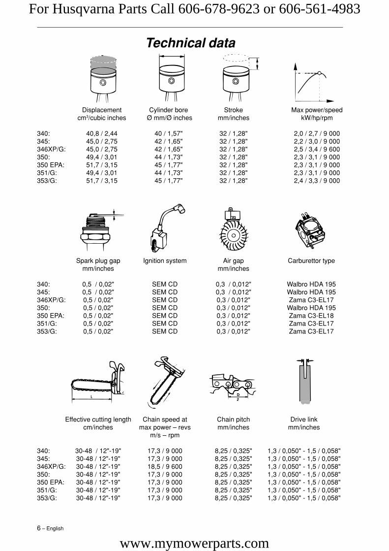
Displacement Cylinder bore Stroke Max power/speedcm3/cubic inches Ø mm/Ø inches mm/inches kW/hp/rpm
340: 40,8 / 2,44 40 / 1,57" 32 / 1,28" 2,0 / 2,7 / 9 000345: 45,0 / 2,75 42 / 1,65" 32 / 1,28" 2,2 / 3,0 / 9 000346XP/G: 45,0 / 2,75 42 / 1,65" 32 / 1,28" 2,5 / 3,4 / 9 600350: 49,4 / 3,01 44 / 1,73" 32 / 1,28" 2,3 / 3,1 / 9 000350 EPA: 51,7 / 3,15 45 / 1,77" 32 / 1,28" 2,3 / 3,1 / 9 000351/G: 49,4 / 3,01 44 / 1,73" 32 / 1,28" 2,3 / 3,1 / 9 000353/G: 51,7 / 3,15 45 / 1,77" 32 / 1,28" 2,4 / 3,3 / 9 000
Spark plug gap Ignition system Air gap Carburettor typemm/inches mm/inches
340: 0,5 / 0,02" SEM CD 0,3 / 0,012" Walbro HDA 195345: 0,5 / 0,02" SEM CD 0,3 / 0,012" Walbro HDA 195346XP/G: 0,5 / 0,02" SEM CD 0,3 / 0,012" Zama C3-EL17350: 0,5 / 0,02" SEM CD 0,3 / 0,012" Walbro HDA 195350 EPA: 0,5 / 0,02" SEM CD 0,3 / 0,012" Zama C3-EL18351/G: 0,5 / 0,02" SEM CD 0,3 / 0,012" Zama C3-EL17353/G: 0,5 / 0,02" SEM CD 0,3 / 0,012" Zama C3-EL17
Effective cutting length Chain speed at Chain pitch Drive linkcm/inches max power – revs mm/inches mm/inches
m/s – rpm
340: 30-48 / 12"-19" 17,3 / 9 000 8,25 / 0,325" 1,3 / 0,050" - 1,5 / 0,058"345: 30-48 / 12"-19" 17,3 / 9 000 8,25 / 0,325" 1,3 / 0,050" - 1,5 / 0,058"346XP/G: 30-48 / 12"-19" 18,5 / 9 600 8,25 / 0,325" 1,3 / 0,050" - 1,5 / 0,058"350: 30-48 / 12"-19" 17,3 / 9 000 8,25 / 0,325" 1,3 / 0,050" - 1,5 / 0,058"350 EPA: 30-48 / 12"-19" 17,3 / 9 000 8,25 / 0,325" 1,3 / 0,050" - 1,5 / 0,058"351/G: 30-48 / 12"-19" 17,3 / 9 000 8,25 / 0,325" 1,3 / 0,050" - 1,5 / 0,058"353/G: 30-48 / 12"-19" 17,3 / 9 000 8,25 / 0,325" 1,3 / 0,050" - 1,5 / 0,058"
Technical data
For Husqvarna Parts Call 606-678-9623 or 606-561-4983
www.mymowerparts.com
English – 7
Technical data
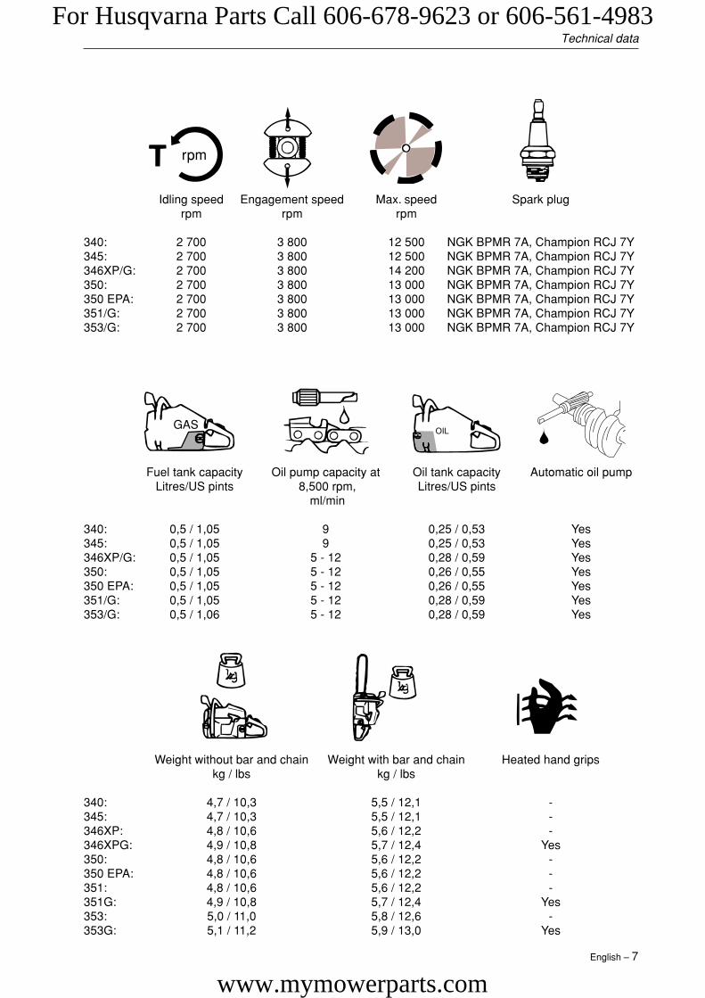
Idling speed Engagement speed Max. speed Spark plugrpm rpm rpm
340: 2 700 3 800 12 500 NGK BPMR 7A, Champion RCJ 7Y345: 2 700 3 800 12 500 NGK BPMR 7A, Champion RCJ 7Y346XP/G: 2 700 3 800 14 200 NGK BPMR 7A, Champion RCJ 7Y350: 2 700 3 800 13 000 NGK BPMR 7A, Champion RCJ 7Y350 EPA: 2 700 3 800 13 000 NGK BPMR 7A, Champion RCJ 7Y351/G: 2 700 3 800 13 000 NGK BPMR 7A, Champion RCJ 7Y353/G: 2 700 3 800 13 000 NGK BPMR 7A, Champion RCJ 7Y
Fuel tank capacity Oil pump capacity at Oil tank capacity Automatic oil pumpLitres/US pints 8,500 rpm, Litres/US pints
ml/min
340: 0,5 / 1,05 9 0,25 / 0,53 Yes345: 0,5 / 1,05 9 0,25 / 0,53 Yes346XP/G: 0,5 / 1,05 5 - 12 0,28 / 0,59 Yes350: 0,5 / 1,05 5 - 12 0,26 / 0,55 Yes350 EPA: 0,5 / 1,05 5 - 12 0,26 / 0,55 Yes351/G: 0,5 / 1,05 5 - 12 0,28 / 0,59 Yes353/G: 0,5 / 1,06 5 - 12 0,28 / 0,59 Yes
Weight without bar and chain Weight with bar and chain Heated hand gripskg / lbs kg / lbs
340: 4,7 / 10,3 5,5 / 12,1 -345: 4,7 / 10,3 5,5 / 12,1 -346XP: 4,8 / 10,6 5,6 / 12,2 -346XPG: 4,9 / 10,8 5,7 / 12,4 Yes350: 4,8 / 10,6 5,6 / 12,2 -350 EPA: 4,8 / 10,6 5,6 / 12,2 -351: 4,8 / 10,6 5,6 / 12,2 -351G: 4,9 / 10,8 5,7 / 12,4 Yes353: 5,0 / 11,0 5,8 / 12,6 -353G: 5,1 / 11,2 5,9 / 13,0 Yes
rpm
GASOIL
For Husqvarna Parts Call 606-678-9623 or 606-561-4983
www.mymowerparts.com
8 – English
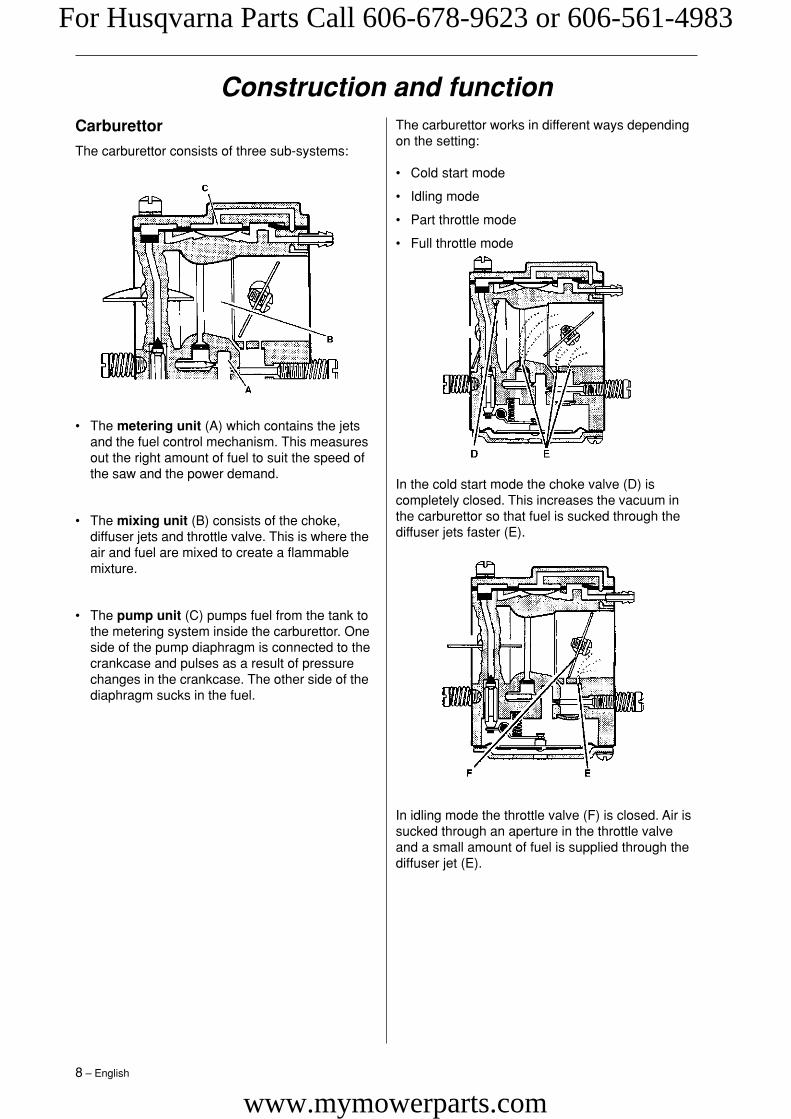
The carburettor works in different ways dependingon the setting:
• Cold start mode
• Idling mode
• Part throttle mode
• Full throttle mode
In the cold start mode the choke valve (D) iscompletely closed. This increases the vacuum inthe carburettor so that fuel is sucked through thediffuser jets faster (E).
In idling mode the throttle valve (F) is closed. Air issucked through an aperture in the throttle valveand a small amount of fuel is supplied through thediffuser jet (E).
Construction and functionCarburettor
The carburettor consists of three sub-systems:
• The metering unit (A) which contains the jetsand the fuel control mechanism. This measuresout the right amount of fuel to suit the speed ofthe saw and the power demand.
• The mixing unit (B) consists of the choke,diffuser jets and throttle valve. This is where theair and fuel are mixed to create a flammablemixture.
• The pump unit (C) pumps fuel from the tank tothe metering system inside the carburettor. Oneside of the pump diaphragm is connected to thecrankcase and pulses as a result of pressurechanges in the crankcase. The other side of thediaphragm sucks in the fuel.
For Husqvarna Parts Call 606-678-9623 or 606-561-4983
www.mymowerparts.com

English – 9
Construction and function
In part throttle mode the throttle valve (F) is par-tially open. Fuel is supplied through the diffuser jets(E).
In full throttle mode both valves are open and fuelis supplied through all the diffuser jets (E).
For Husqvarna Parts Call 606-678-9623 or 606-561-4983
www.mymowerparts.com

10 – English
Troubleshooting
Worn needle valveLeaking control diaphragm/cover plateNeedle valve assembly stickingWorn needle valve leverFaulty diffuser jet
Fuel filter blockedFuel line blockedLeaking air intake hose (rubber)Loose carburettor mountingboltsWorn throttle valve pivotLoose throttle valve screwWorn throttle valveNeedle valve assemblystickingLeak in metering system (airor fuel)Metering system centre knobis wornHole in diaphragmLeaking control diaphragm/cover plateCrankcase leaking
Fuel line blockedNeedle valve set too highNeedle valve assembly stickingLeak in metering system (airor fuel)Leaking control diaphragm/cover plateFaulty diffuser jetsCrankcase leaking
Needle valve set too highNeedle valve assembly stickingMetering system damagedWorn needle valveLeaking control diaphragm/cover plateMetering system incorrectlyassembled
Adjust L screwAir filter blockedChoke not workingWorn choke pivotWorn choke valveFuel filter blockedFuel line blockedPiston ring seizedBlocked impulse channel
Loose or faulty fuel pipeHole in diaphragmWorn needle valveNeedle valve assembly stickingNeedle valve set too highLeak in metering system (airor fuel)Loose cover on carburettorpump side
Worn needle valveNeedle valve set too highNeedle valve assembly sticking
Difficulty starting
Carburettorleaking fuel
Flooding whenengine notrunning
Starting
The various faults that can affect a chainsaw are divided into four groups. In each group the likely symp-toms are given on the left and possible causes are listed on the right. The most likely faults are given first,and so on.
Idling (low rpm)
Idles when Lscrew closed
Idling uneven
L screw requiresconstantadjustment
Too much fuel atidling
Idling (low rpm) (cont.)
Adjust L screwLeaking air intake hose(rubber)Loose carburettor mountingboltsLoose or faulty fuel hoseFuel filter blockedFuel line blockedFuel tank vent blockedThrottle valve pivot stiffThrottle pushrod stickingDefective throttle return springBent throttle stopFaulty diffuser jet
Adjust L screwWorn needle valveNeedle valve set too highWorn needle valve leverLeaking control diaphragm/cover plateNeedle valve assemblysticking
Will not idle
Idling too rich
For Husqvarna Parts Call 606-678-9623 or 606-561-4983
www.mymowerparts.com

English – 11
Troubleshooting
Acceleration and retardation
Does notaccelerate
Engine stallswhen throttlereleased
Over richacceleration
Adjust L screwAdjust H screwBlocked air filterBlocked fuel tank ventBlocked fuel filterFuel line blockedLoose or damaged fuel hoseImpulse channel blockedLoose cover on carburettor pumpsideFaulty pump diaphragmLeaking air intake hose (rubber)Loose carburettor mounting boltsNeedle valve set too lowMetering system incorrectlyassembledNeedle valve assembly stickingFaulty diffuser jetsBlocked silencer
Adjust L screwAdjust H screwFaulty pump diaphragmNeedle valve set too highNeedle valve assembly stickingFaulty diffuser jets
Adjust L screwAdjust H screwBlocked air filterFaulty pump diaphragmFaulty diffuser jets
Troubleshooting methodsIn addition to the faults described in the abovetable, trouble shooting can be carried out onspecific components or sub-systems of thechainsaw. The various procedures are described inthe relevant chapters, see the contents page, asfollows:
• Checking the operation of the chain brake
• Measuring the resistance of the stop plate
• Pressure testing the carburettor
• Pressure testing the decompression valve
• Pressure testing the cylinder
Adjust H screwBlocked air filterBlocked fuel tank ventBlocked fuel filterFuel line blockedLoose or damaged fuel hoseImpulse channel leakingImpulse channel blockedLoose cover on carburettor pumpsideFaulty pump diaphragmLeaking air intake hose (rubber)Loose carburettor mounting boltsNeedle valve set too lowMetering system damagedMetering system incorrectlyassembledLeaking control diaphragm/coverplateNeedle valve assembly stickingBlocked silencer
Adjust H screwBlocked fuel tank ventBlocked fuel filterImpulse channel leakingImpulse channel blockedLoose cover on carburettor pumpsideFaulty pump diaphragmBlocked air filterNeedle valve assembly stickingLeak in metering system (air or fuel)Metering system incorrectlyassembledLoose diaphragm rivetHole in diaphragmLeaking control diaphragm/coverplate
Blocked fuel tank ventBlocked fuel filterFuel line blockedLoose or damaged fuel hoseImpulse channel leakingImpulse channel blockedLoose cover on carburettor pumpsideFaulty pump diaphragmLeaking air intake hose (rubber)Loose carburettor mounting boltsNeedle valve set too lowLeak in metering system (air or fuel)Metering unit incorrectly assembledLoose diaphragm rivetHole in diaphragmLeaking control diaphragm/coverplate
Will not run atfull throttle
Low power
Will not “four-stroke”
High rpm
For Husqvarna Parts Call 606-678-9623 or 606-561-4983
www.mymowerparts.com

12 – English
3
WARNING!Make sure the spring does not flyout and cause injury. Wear eyeprotection.
Repair instructionsChain brake – dismantling
1
Disengage the brake by pushing the kickbackguard backwards. Unscrew the guide bar bolts andremove the clutch cover, chain and guide bar.
2
Grip the clutch cover carefully in a vice. Releasethe brake spring by using the kickback guard fromthe saw as a tool. Engage it with the brake mecha-nism and turn anticlockwise to activate the brake.
Remove the screws and carefully remove the coverfrom the chain brake spring.
4
Place one hand over the spring and insert a smallscrewdriver between the bottom end of the springand the clutch cover. Carefully prise the springupwards so that it slides onto the screwdriver shaft.
Cleaning and inspection
• Clean and inspect all parts carefully. If there areany cracks or other defects replace the damagedparts with new ones. Always use original parts.
• Measure the thickness of the chain brake band.It must be no less than 0.6 mm at any point.
• Lubricate the elbow joint with grease.
min 0,6 mm
For Husqvarna Parts Call 606-678-9623 or 606-561-4983
www.mymowerparts.com

English – 13
Repair instructions
NOTE!
After completing the repair the chainbrake must be tested as described below.
Operating test:
The engine must not be running during the test.
Guide bar length Height
38cm/15" 50 cm/20"
• Hold the chainsaw over a firm surface. Theheight of the guide bar above the surface isgiven in the table above.
• Let go of the front handle and let the chainsawfall towards the surface.
• When the guide bar hits the surface the chainbrake must engage.
Chain brake – reassembly
1
Bolt the elbow joint to the brake band and tightento a torque of 1–1.5 Nm.Locate the elbow joint and connected brake bandin their recesses in the clutch cover. Lubricate therecess for the spring with grease.
2
Grip the clutch cover in a vice. Compress thespring with special tool 502 50 67-01 and push itdown with your thumb.
3
Fit the cover over the chain brake spring, tighteningthe screws to a torque of 1–1.5 Nm.
4
Tension the brake spring by using the kickbackguard from the saw as a tool. Engage it with thebrake mechanism and turn clockwise to releasethe brake.
5Turn the chain tensioner anticlockwise as far as itwill go.
Refit:
• guide bar
• chain
• clutch cover
WARNING!Make sure the spring does not flyout and cause injury. Wear eyeprotection.
For Husqvarna Parts Call 606-678-9623 or 606-561-4983
www.mymowerparts.com
14 – English
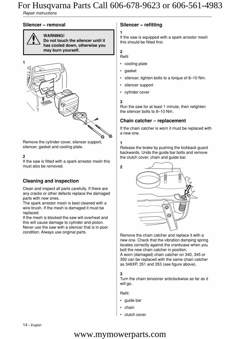
WARNING!Do not touch the silencer until ithas cooled down, otherwise youmay burn yourself.
Repair instructions
Remove the chain catcher and replace it with anew one. Check that the vibration damping springlocates correctly against the crankcase when youbolt the new chain catcher in position.A worn (damaged) chain catcher on 340, 345 or350 can be replaced with the same chain catcheras 346XP, 351 and 353 (see figure above).
3Turn the chain tensioner anticlockwise as far as itwill go.
Refit:
• guide bar
• chain
• clutch cover
Silencer – removal
Remove the cylinder cover, silencer support,silencer, gasket and cooling plate.
2If the saw is fitted with a spark arrestor mesh thismust also be removed.
Cleaning and inspection
Clean and inspect all parts carefully. If there areany cracks or other defects replace the damagedparts with new ones.The spark arrestor mesh is best cleaned with awire brush. If the mesh is damaged it must bereplaced.If the mesh is blocked the saw will overheat andthis will cause damage to cylinder and piston.Never use the saw with a silencer that is in poorcondition. Always use original parts.
Silencer – refitting
1If the saw is equipped with a spark arrestor meshthis should be fitted first.
2Refit
• cooling plate
• gasket
• silencer, tighten bolts to a torque of 8–10 Nm.
• silencer support
• cylinder cover
3Run the saw for at least 1 minute, then retightenthe silencer bolts to 8–10 Nm.
Chain catcher – replacement
If the chain catcher is worn it must be replaced witha new one.
1Release the brake by pushing the kickback guardbackwards. Undo the guide bar bolts and removethe clutch cover, chain and guide bar.
2
1
For Husqvarna Parts Call 606-678-9623 or 606-561-4983
www.mymowerparts.com

English – 15
Repair instructions
Stop switch – removal
1Remove the cylinder cover and air filter.
2
Disconnect both leads from the stop plate and stopswitch. Remove the stop plate by carefully sliding itover the lug on the front mounting.
3
Carefully prise the carburettor assembly off the left-hand rubber mounting using a small screwdriver.
4
Carefully prise the stop switch’s upper mounting offthe air filter holder while lifting the switch to releaseit from the lower mounting.
Measure the resistance by connecting a multimeterto the ignition coil. NOTE! The switch must be inthe “on” position to give the correct reading.
The resistance must not be higher than 0.2 ohmwhen the switch is in the on position.
Stop switch – resistance measurement
Clean the mating surfaces and check the resist-ance as follows:
Cleaning and inspection
Clean and inspect all parts carefully. If there areany cracks or other defects replace the damagedparts with new ones. Always use original parts.
For Husqvarna Parts Call 606-678-9623 or 606-561-4983
www.mymowerparts.com

16 – English
Repair instructions
Choke control – removal
1Remove the cylinder cover, air filter and stopswitch. Disconnect the fuel hose from the carburet-tor.
Stop switch – refitting
1
Carefully press the new stop switch into place.Check that the switch’s upper mounting clips overthe air filter holder.
2
Refit the stop plate. Engage the stop plate in thefront slot first then lift the rear edge onto the stopswitch. Slide the stop plate in as far as it will go.
3Refit:
• the leads to the stop plate and stop switch
• air filter
• cylinder
Disconnect the pushrod from the carburettor by firstcarefully prising up the spring over the end of therod, where it connects to the throttle lever (A). Thenpress the throttle lever forwards (B) while pressingthe throttle pushrod backwards (C) and lifting it offthe lever. Withdraw the throttle pushrod from thetank and lift it upwards without pulling it through therubber inlet manifold. Carefully release the carbu-rettor assembly from the right-hand rubber mount-ing and lift it upwards.
NOTE!
Do not use knurled pliers to disconnect orreconnect the fuel hose. This coulddamage the hose and lead to leakage orfracture.
Compress the clip that holds the choke control tothe carburettor while pulling it out at the same time.Disconnect the choke control from the air filterholder.
3
2
C
A
B
For Husqvarna Parts Call 606-678-9623 or 606-561-4983
www.mymowerparts.com

English – 17
Repair instructions
Cleaning and inspection
• Clean and inspect all parts carefully. If there areany cracks or other defects replace the damagedparts with new ones. Always use original parts.
• Lubricate the throttle lock with oil.
• Check that the spring is not broken and has notlost its tension.
Throttle lock, throttle trigger and returnspring – refitting
1
Throttle lock, throttle trigger and returnspring – removal
1
Remove the throttle lock by pressing it to the left(A) and carefully levering it up with a screwdriveron the clutch side (B) of the saw to disengage thelugs on either side of the throttle lock from the fueltank. When both lugs are clear of the tank, pull thelock backwards (C).
Drive out the steel pin using a 2.5 mm/0.1" diam-eter drift (A). Push it out from the flywheel side ofthe saw. Remove the throttle trigger by first press-ing it towards the clutch side of the saw (B) until itclicks, then towards the flywheel side until it clicksagain. Remove it from the tank and lift out thereturn spring.
2
Choke control – refitting
First reattach the choke control to the air filter, thenpress it onto the carburettor so that the clips engage.
Then refit:
• stop switch
• carburettor into its rubber mountings
• throttle pushrod into the fuel tank and connect tothrottle lever.
• lift the spring arm over the throttle pushrod
• fuel hose to the carburettor
• air filter and cylinder cover
Refit the return spring to the throttle trigger asshown. Make sure the spring is correctly positionedby engaging one end in the slot in the throttletrigger (A).
2First insert the rear edge of the throttle trigger intothe tank. Then push/clip the front edge into the twoclips on the tank with the aid of a combination tool,for example. Drive in the steel pin from the clutchside. Use a 2.5 mm/0.1" diameter drift.
3Then press down the return spring while pressingthe throttle lock forwards/upwards into the retainingclip in the fuel tank until you hear a click. Releasethe return spring in the throttle lock, then press thelock down onto the tank.
4Check the operation of the throttle lock by trying topress the throttle trigger without pressing down thethrottle lock. Also check that the throttle lock andthrottle trigger return freely to their original posi-tions when released.
B
A
C
BAC
A
For Husqvarna Parts Call 606-678-9623 or 606-561-4983
www.mymowerparts.com

18 – English
Hand grip heater on model 346XPG,351G, 353G – removalNo heating or heating only in front hand grip
• Front hand grip – troubleshooting
1
Remove the three bolts that secure the cover overthe front hand grip. Disconnect the leads from theswitch and generator and measure the resistance ofthe hand grip heater, which should be 3–4 ohm.Replace the front hand grip if the resistance is higher.
2
Reconnect the leads and refit the cover.
3Push the switch back into place and reconnect theleads.
4Bolt the cover back onto the hand grip.
• Generator – troubleshooting
1Remove the cylinder cover and cover from thefront hand grip. Disconnect the black lead from thegenerator and connect a multimeter between it anda clean area on the cylinder. The multimeter shouldshow a resistance of 0.9–1.3 ohm. If the reading ishigher or lower, replace the generator, see “Re-placing the generator”.
2Reconnect the lead and refit the hand grip coverand cylinder cover.
• Switch – troubleshooting
1Carefully free the switch and frame from the fronthand grip using a screwdriver.
2Disconnect the leads from the switch and connecta multimeter to it. The meter should read over1000 ohm when the switch is in the “0” position.The meter should read no higher than 0.1 ohm withthe switch in the “1” position. Replace the meter ifthe readings are outside these limits.
Rear hand grip heater not working
• Rear hand grip heater – troubleshooting
1Remove the cylinder cover, air filter and cover fromthe rear hand grip.
2Disconnect the red lead from the heater andconnect a multimeter between it and the blackearth lead that is bolted to the bottom of thecarburettor on the clutch side of the saw. Themeter should read 0.7–1.2 ohm. If the reading ishigher replace the heater element.
3Remove the air filter, throttle pushrod, rubberdiaphragm and carburettor, see “Carburettor –removal”.
4Remove the bolt from the plate at the base of thecarburettor to release the lead for the heaterelement.
5
Repair instructions
Unscrew the three bolts from the front hand gripand remove the cover to reveal the leads. Discon-nect the red lead.
For Husqvarna Parts Call 606-678-9623 or 606-561-4983
www.mymowerparts.com

English – 19
Unscrew the two bolts from the right side of therear hand grip. Remove the throttle lock andthrottle handle, see “Throttle trigger”. Pull out theheater element with the leads still connected.
Troubleshooting carburettor heater(346XPG, 351G, 353G)
OperationThe carburettor temperature is controlled by anelectronic thermostat to eliminate the risk of iceformation in the carburettor. The thermostatswitches on/off at 12°C/54F. This means that thesaw operator does not need to remember to switchthe carburettor heater on or off.
• TroubleshootingFront handle heaterRemove the side cover from the handle. Discon-nect the leads at F and G (see diagram).Clean the connectors. Turn the switch ”on”.Measure the resistance between F and G.The reading should be 4±1 ohms. If not, discon-nect the lead at O and remove the switch.Measure the resistance between O and F. Thereading should be 4±1 ohms. If the resistance isincorrect, replace the front handle.Disconnect the lead at N and G and measure theresistance between these points. The readingshould be no higher than 0.1 ohm. If it is too high,replace the lead.
SwitchMeasure the resistance between N and O with theswitch turned off. The reading should be 1 000ohms or higher.Repeat the measurement with the switch turnedon. The reading should be no higher than 0.1 ohm.If it is too high, replace the switch.
6
Repair instructions
Rear handle heaterMeasure the resistance between F and Z. It shouldbe 1 ± 0.5 ohm.If not, replace the rear handle heater.
GeneratorMeasure the resistance between G and H. Itshould be between 0.3–1.3 ohm.If not, replace the generator.
Carburettor heaterDisconnect the lead at X and clean the connectors.Measure the resistance between X and G.The reading should be between 3–10 ohms. If not,disconnect the lead at Y and clean the connectors.Measure the resistance between X and Y, if thereading is not between 3–7 ohms – replace thecarburettor heater.
O
N
FG
Z
Y
H
K XV
3
5
4
1
VK
O
N
FG
Z
X
Y
H
5
3
4
1
For Husqvarna Parts Call 606-678-9623 or 606-561-4983
www.mymowerparts.com

20 – English
Repair instructions
Heater element and rear hand grip –removal
1Remove the cylinder cover, hand grip cover, handgrip and right-hand stop.
Then remove:
• throttle lock, throttle trigger and recoil spring,see “Throttle trigger”.
• fuel hose and throttle pushrod from the carburettor
Unbolt the rear tank mounting from the crankcase,i.e. the rear vibration damping spring, and bothstops. Lower the tank as far as it will go to allowaccess to the heater lead where it is connected tothe tank.
Refit:
• fuel tank with both stops and the rear vibrationdamping spring
• throttle lock, throttle trigger and recoil spring,see “Throttle trigger”.
• fuel hose and throttle pushrod to the carburettor(check that the hose is not trapped between thetank and crankcase, measurement 43 mm/1.69inches)
• hand grip cover, air filter and cylinder cover
Heater element and rear hand grip –removal
1Screw the heater element into place using the twoscrews and feed the leads through the rear handgrip. Secure the red lead in the clip on the tank andconnect it. Feed the black lead through crankcaseand secure/earth it to the base of the carburettorusing the bolt at the front on the clutch side of thesaw. Tighten to a torque of 3–4 Nm.
2Refit:
• fuel tank with both stops and the rear vibrationdamping spring
• throttle lock, throttle trigger and recoil spring,see “Throttle trigger”.
• fuel hose and throttle pushrod to the carburettor(check that the hose is not trapped between thetank and crankcase, measurement 43 mm/1.69inches)
• hand grip cover, air filter and cylinder cover
Bolt the vibration damping springs that hold thetank unit back in place and refit the cover over thefront hand grip.
Hand grip heater on model 346XPG,351G, 353G – refitting
1Feed the leads into the rear hand grip and insertthe heater element in the hand grip. Screw in thetwo bolts through the right side of the hand grip tosecure the heater.
2
Press the black lead into the base of the carburet-tor and connect it with the bolt.Tighten to a torque of 3–4 Nm.
3Run the red lead to the front hand grip and connectit.
4Press the throttle trigger and throttle lock intoposition and check that they work correctly, see“Throttle trigger”.
5
For Husqvarna Parts Call 606-678-9623 or 606-561-4983
www.mymowerparts.com

English – 21
Repair instructions
WARNING!If the recoil spring is still undertension when the pulley is re-moved it can fly out and cause in-jury. Wear eye protection.
Starter assembly – removal
1
Undo the four bolts that fasten the starter assemblyto the crankcase and lift off the starter assembly.
2Pull out about 30 cm of the cord and fasten it in thenotch in the pulley rim. Release the tension in thereturn spring by letting the pulley wind backwardsslowly.
3
Remove the bolt from the centre of the pulley andlift off the pulley.
Cleaning and inspection
Clean the parts and check the following:
• The starter cord.
• The teeth on the pulley, lubricate with oil.
• That the pawls on the flywheel are undamaged,i.e. that they spring back towards the centre andmove freely.
• Lubricate the return spring with light oil.
Replacing a broken or worn starter cord
1
Before replacing a worn starter cord the tension in therecoil spring must be released. Pull the starter cord outthrough the notch in the pulley rim and wind the pulleyanti-clockwise to release the tension in the spring.
2Remove the bolt from the centre of the pulley andlift off the pulley.
3
Fit a new cord through the hole in the pulley and tiea knot to secure it. Feed the other end of the cordthrough the hole in the starter housing and throughthe starter handle, then tie a double knot in theend. Wind about 3 turns of the starter cord onto thepulley. Fit the bolt through the centre of the pulleyand tighten to a torque of 2–3 Nm.
For Husqvarna Parts Call 606-678-9623 or 606-561-4983
www.mymowerparts.com

22 – English
Repair instructions
WARNING!Make sure the recoil spring doesnot fly out and cause injury. Weareye protection.
Replacing a worn recoil spring
1Remove the bolt from the centre of the pulley andlift off the pulley and spring.
2Remove the broken recoil spring.
3Fit the bolt through the centre of the pulley andtighten to a torque of 2–3 Nm.Tension the recoil spring, see “Tensioning the recoilspring”.
Position the starter assembly on the crankcase andtighten the bolts to a torque of 2.5–3.5 Nm.
Starter assembly – refitting
1Tensioning the recoil spring
1Fasten the starter cord in the notch in the pulleyrim and wind the pulley about 2 turns clockwise.Check that the pulley is free to rotate at leastanother half turn when the starter cord is fullyextended.
Cleaning and inspection:
• Clean and inspect all parts carefully. If there areany cracks or other defects replace the dam-aged parts with new ones. Lubricate the returnspring with light oil.
For Husqvarna Parts Call 606-678-9623 or 606-561-4983
www.mymowerparts.com

English – 23
Repair instructions
Ignition module – testing
If there is a fault in the ignition system the ignitionmodule must be tested before the ignition systemis removed.
Test the ignition module as follows:
• Connect a test spark plug 502 71 13-01 to theignition lead and clip the test spark plug onto thecylinder.
• Turn the engine over using the starter cord.
• If the test spark plug produces a spark theignition module is OK.
Ignition module/flywheel – removal
1
Remove the cylinder cover. Disconnect the HT lead,remove the spark plug and fit piston stop 502 54 15-01 in its place. Take off the starter assembly, releasethe leads from the cable guide and remove it.
Model 346XP, 351, 353:Remove the cover from the hand grip.
If replacing the ignition module, disconnect its leadsand unscrew it. The ignition module can be left inplace if you are simply removing the flywheel.
3
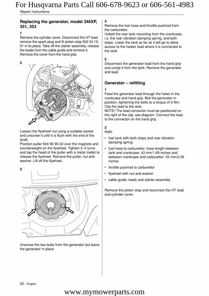
Loosen the flywheel nut using a suitable socket andunscrew it until it is flush with the end of the shaft.
4
Position puller 504 90 90-02 over the magnets andcounterweight on the flywheel. Tighten 2–3 turnsand tap the head of the puller with a metal mallet torelease the flywheel. Remove the puller, nut andwasher. Lift off the flywheel.
Cleaning and inspection
• Clean all parts, especially the tapers on theflywheel and shaft.
• Check that the flywheel is not cracked or dam-aged in any other way.
2
For Husqvarna Parts Call 606-678-9623 or 606-561-4983
www.mymowerparts.com
24 – English
Repair instructions
Generator – refitting
1Feed the generator lead through the holes in thecrankcase and hand grip. Bolt the generator inposition, tightening the bolts to a torque of 5 Nm.Clip the lead to the tank.NOTE! The lead connector must be positioned onthe right of the clip, see diagram. Connect the leadto the connector on the hand grip.
2Refit:
• fuel tank with both stops and rear vibrationdamping spring
• fuel hose to carburettor, hose length betweentank and crankcase: 43 mm/1.69 inches andbetween crankcase and carburettor: 53 mm/2.09inches
• throttle pushrod to carburettor
• flywheel with nut and washer
• cable guide, leads and starter assembly
Remove the piston stop and reconnect the HT leadand cylinder cover.
4Remove the fuel hose and throttle pushrod fromthe carburettor.Unbolt the rear tank mounting from the crankcase,i.e. the rear vibration damping spring, and bothstops. Lower the tank as far as it will go to allowaccess to the heater lead where it is connected tothe tank.
5Disconnect the generator lead from the hand gripand unclip it from the tank. Remove the generatorand lead.
Replacing the generator, model 346XP,351, 353
1Remove the cylinder cover. Disconnect the HT lead,remove the spark plug and fit piston stop 502 54 15-01 in its place. Take off the starter assembly, releasethe leads from the cable guide and remove it.Remove the cover from the hand grip.
2
Loosen the flywheel nut using a suitable socketand unscrew it until it is flush with the end of theshaft.Position puller 504 90 90-02 over the magnets andcounterweight on the flywheel. Tighten 2–3 turnsand tap the head of the puller with a metal mallet torelease the flywheel. Remove the puller, nut andwasher. Lift off the flywheel.
3
Unscrew the two bolts from the generator but leavethe generator in place.
For Husqvarna Parts Call 606-678-9623 or 606-561-4983
www.mymowerparts.com

English – 25
Repair instructions
3
Then refit:
• cable guide and press the leads into position
• HT lead
• starter assembly, tighten to a torque of 2.5–3.5Nm
• cylinder cover
Ignition module and flywheel – refitting
1
Place the flywheel on the crankshaft. Turn theflywheel so that the key lines up with the keyway inthe shaft.Fit the washer and nut on the shaft and tighten to atorque of 25-30 Nm.
2
To refit the ignition module proceed as follows:
Turn the flywheel so that the magnets are in linewith the ignition module. Fit the ignition modulewith the plastic feeler gauge (502 51 34-01) held inposition at the same time, without tightening thebolts. Connect the black earth lead to the frontscrew on the ignition module. Adjust the gapbetween the ignition module and magnet to 0.3 +/-0.1 mm. The gap must be measured at either ofthe two lowest pegs on the ignition module.Tighten the bolts to 4.5–6 Nm. Connect the bluelead to the ignition module.
0,3 mm
For Husqvarna Parts Call 606-678-9623 or 606-561-4983
www.mymowerparts.com
26 – English
Repair instructions
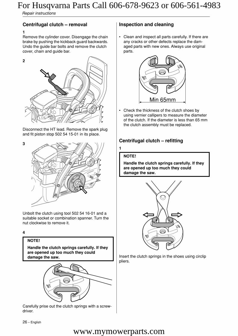
Centrifugal clutch – removal
1Remove the cylinder cover. Disengage the chainbrake by pushing the kickback guard backwards.Undo the guide bar bolts and remove the clutchcover, chain and guide bar.
2
Unbolt the clutch using tool 502 54 16-01 and asuitable socket or combination spanner. Turn thenut clockwise to remove it.
4
NOTE!
Handle the clutch springs carefully. If theyare opened up too much they coulddamage the saw.
Carefully prise out the clutch springs with a screw-driver.
Inspection and cleaning
• Clean and inspect all parts carefully. If there areany cracks or other defects replace the dam-aged parts with new ones. Always use originalparts.
• Check the thickness of the clutch shoes byusing vernier callipers to measure the diameterof the clutch. If the diameter is less than 65 mmthe clutch assembly must be replaced.
NOTE!
Handle the clutch springs carefully. If theyare opened up too much they coulddamage the saw.
Centrifugal clutch – refitting
1
Insert the clutch springs in the shoes using circlippliers.
Min 65mm
Disconnect the HT lead. Remove the spark plugand fit piston stop 502 54 15-01 in its place.
3
For Husqvarna Parts Call 606-678-9623 or 606-561-4983
www.mymowerparts.com

English – 27
Repair instructions
Fit the clutch onto the crankshaft and tightenanticlockwise as far as it will go. Then tighten to atorque of at least 20 Nm using tool 502 54 16-01and a suitable socket or combination spanner.
3Remove the piston stop. Fit the spark plug, tighteningit to a torque of 15 Nm, then connect the HT lead.
Then refit:
• cylinder cover
• guide bar
• chain
• clutch cover
2
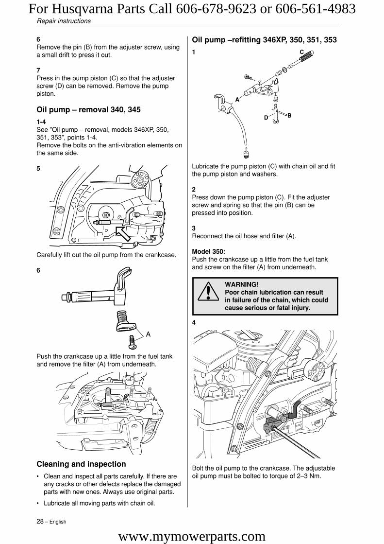
Oil pump – removal 346XP, 350, 351,353
1Empty and clean the oil tank.
2
3
Unbolt and remove the clutch drum (A), RIM chainsprocket (B) if fitted, needle bearing (C) and pumpdrive wheel (D).
Model 350:Remove the bolts on the anti-vibration elements onthe same side.
4
A
CD
B
Remove the cylinder cover. Disengage the chainbrake by pushing the kickback guard backwards.Undo the guide bar bolts and remove the clutchcover, chain and guide bar. Disconnect the HTlead. Remove the spark plug and fit piston stop502 54 15-01 in its place. Unscrew the clutch(clockwise) using clutch tool 502 54 16-01 and asuitable socket spanner or combination spanner.
Unbolt the oil pump from the crankcase.
5
B
A
C
D
Remove the oil hose and filter (A).
Model 350:Push the housing up a little from the fuel tank andremove the filter (A) from underneath, see thediagram under “Oil pump – removal 340, 345”.
For Husqvarna Parts Call 606-678-9623 or 606-561-4983
www.mymowerparts.com
28 – English
Repair instructions
Cleaning and inspection
• Clean and inspect all parts carefully. If there areany cracks or other defects replace the damagedparts with new ones. Always use original parts.
• Lubricate all moving parts with chain oil.
Carefully lift out the oil pump from the crankcase.
6
Push the crankcase up a little from the fuel tankand remove the filter (A) from underneath.
6Remove the pin (B) from the adjuster screw, usinga small drift to press it out.
7Press in the pump piston (C) so that the adjusterscrew (D) can be removed. Remove the pumppiston.
Oil pump – removal 340, 345
1-4See ”Oil pump – removal, models 346XP, 350,351, 353”, points 1-4.Remove the bolts on the anti-vibration elements onthe same side.
5
4
Bolt the oil pump to the crankcase. The adjustableoil pump must be bolted to torque of 2–3 Nm.
WARNING!Poor chain lubrication can resultin failure of the chain, which couldcause serious or fatal injury.
Lubricate the pump piston (C) with chain oil and fitthe pump piston and washers.
2Press down the pump piston (C). Fit the adjusterscrew and spring so that the pin (B) can bepressed into position.
3Reconnect the oil hose and filter (A).
Model 350:Push the crankcase up a little from the fuel tankand screw on the filter (A) from underneath.
Oil pump –refitting 346XP, 350, 351, 353
1
B
A
C
D
For Husqvarna Parts Call 606-678-9623 or 606-561-4983
www.mymowerparts.com
English – 29
Repair instructions
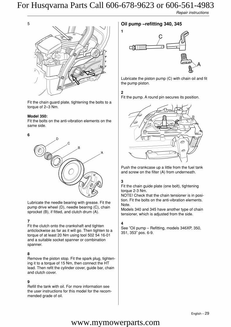
Fit the chain guard plate, tightening the bolts to atorque of 2–3 Nm.
Model 350:Fit the bolts on the anti-vibration elements on thesame side.
6
5
A
CD
B
Lubricate the needle bearing with grease. Fit thepump drive wheel (D), needle bearing (C), chainsprocket (B), if fitted, and clutch drum (A).
7Fit the clutch onto the crankshaft and tightenanticlockwise as far as it will go. Then tighten to atorque of at least 20 Nm using tool 502 54 16-01and a suitable socket spanner or combinationspanner.
8Remove the piston stop. Fit the spark plug, tighten-ing it to a torque of 15 Nm, then connect the HTlead. Then refit the cylinder cover, guide bar, chainand clutch cover.
9Refill the tank with oil. For more information seethe user instructions for this model for the recom-mended grade of oil.
Oil pump –refitting 340, 345
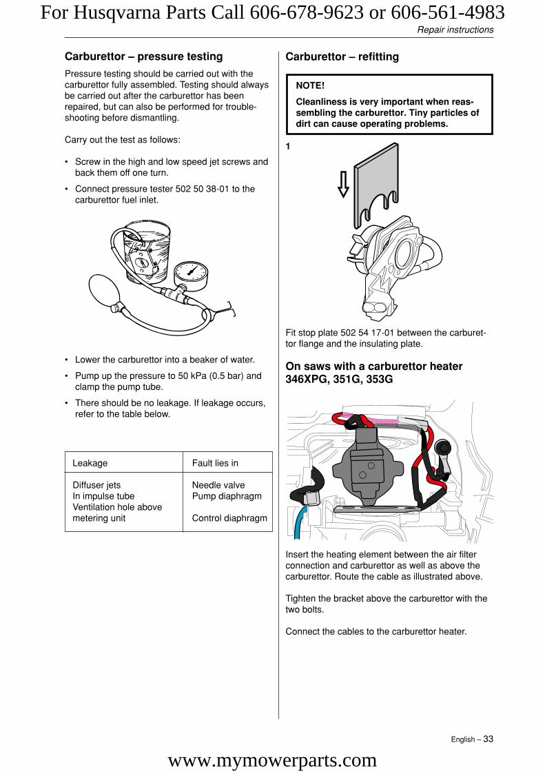
1
Lubricate the piston pump (C) with chain oil and fitthe pump piston.
2Fit the pump. A round pin secures its position.
Push the crankcase up a little from the fuel tankand screw on the filter (A) from underneath.
3Fit the chain guide plate (one bolt), tighteningtorque 2-3 Nm.NOTE! Check that the chain tensioner is in posi-tion. Fit the bolts on the anti-vibration elements.Note.Models 340 and 345 have another type of chaintensioner, which is adjusted from the side.
4See ”Oil pump – Refitting, models 346XP, 350,351, 353” pos. 6-9.
For Husqvarna Parts Call 606-678-9623 or 606-561-4983
www.mymowerparts.com

30 – English
Repair instructions
Recommended setting:13–15" bar Min. setting15–18" bar Midway setting18–20" bar Max. setting
Adjustable oil pump – adjustment346XP, 350, 351, 353
Use a screwdriver or adjustable spanner to turn theadjuster screw on the pump. Turning the screwclockwise decreases the oil flow and turning it anti-clockwise increases the oil flow.
–+12
3
Undo and remove the carburettor bolts. Lift off thecarburettor.
Open the spring lock on the rubber bellows.
4
Carburettor – removal
1
Remove the cylinder and air filter. Disconnect theleads from the stop switch and the fuel hose fromthe carburettor.
NOTE!
Do not use knurled pliers to disconnect orreconnect the fuel hose. This coulddamage the hose and lead to leakage orfracture.
C
A
B
Disconnect the pushrod from the carburettor byfirst carefully prising up the spring over the end ofthe rod, where it connects to the throttle lever (A).Then press the throttle lever forwards (B) whilepressing the throttle pushrod backwards (C) andlifting it off the lever. Withdraw the throttle pushrodfrom the tank and lift it upwards without pulling itthrough the rubber inlet manifold. Carefully releasethe carburettor assembly from the right-handrubber mounting and lift it upwards.
3
2
For Husqvarna Parts Call 606-678-9623 or 606-561-4983
www.mymowerparts.com

English – 31
Repair instructions
When replacing the thermostat: Disconnect thecable from X and V. Trouble shooting, see page20.
On saws with carburettor 346XPG, 351G, 353GReplacing the heating element: Lower the rearsection of the tank by removing the bolt betweenthe hand grip cover and vibration damping springs.Remove the starter and then loosen the stopscrews on both sides (one is located under thestarter and this must be removed first). Nowdisconnect the cable from X and Y.
Dismantling the carburettor: Loosen the high, lowand idling jet screws.
O
N
FG
Z
Y
H
K XV
3
5
4
1
VK
O
N
FG
Z
X
Y
H
5
3
4
1
On saws with a carburettor heater 346XPG,351G, 353G
Remove the bracket’s two bolts above the carbu-rettor. Disconnect the cable connections to thecarburettor heater and remove the heating ele-ment.
Heating element
Carburettor – dismantling
The item numbers in the diagram refer to the stepsbelow (1–7).
1Remove the cover from the metering unit andcarefully remove the metering diaphragm andgasket.
2Undo the screw and take out the needle valve,together with the lever arm, spindle and spring.
3Remove the cover from the pump unit and carefullyremove the gasket and pump diaphragm.
4Remove the fuel filter.
5Remove the high, low and idling jet screws. (HDA159A high and low jet screws are protected byplastic caps which can be prised off with a screw-driver. Only on EPA, see appendix A.)
6Remove the plug by first drilling a hole in it andthen prising it out with a screwdriver or the like.
7If necessary remove the throttle and choke valves,and remove the spindles together with the leverarms and springs.
For Husqvarna Parts Call 606-678-9623 or 606-561-4983
www.mymowerparts.com

32 – English
Repair instructions
Fit the needle valve with lever arm, spindle andspring and tighten the screw.Use a rule to check that the lever arm is level withthe cover face. If necessary, the lever arm can bebent slightly.
7Fit the metering diaphragm with its gasket and refitthe cover to the metering unit.
8Carry out pressure testing.
1If the throttle and choke butterflies and theirspindles were removed, these must be refitted.Lubricate the spindle bearings with light oil.
2Insert the plug in the hole with the convex sideupwards and expand it by pressing downwardswith a drift.
3Refit the high and low speed jet screws andsprings, plus the idling screw. Fit the plastic capsover the high and low speed screws.
4Fit the fuel filter, using the handle of a small screw-driver.
5Fit the pump diaphragm, gasket and cover to thepump unit.
6
Cleaning and inspection
Clean all the carburettor components in petrol. Usean airline to dry off the petrol from all components.Blow through all the channels in the carburettorbody and check that they are not blocked.
Check that:
• The gasket, pump diaphragm and meteringdiaphragm are undamaged.
• There is no play in the throttle and choke valves.
• The needle valve and its lever arm are not worn.
• The fuel filter is undamaged.
• The tips of the high and low speed jet screwsare not damaged.
• The air intake duct is not cracked.
Carburettor – reassembly
NOTE!
Cleanliness is very important whenreassembling the carburettor. Tiny parti-cles of dirt can cause operating problems.
The item numbers in the diagram refer to the stepsbelow (1–8).
For Husqvarna Parts Call 606-678-9623 or 606-561-4983
www.mymowerparts.com
English – 33
Repair instructions
Carburettor – pressure testing
Pressure testing should be carried out with thecarburettor fully assembled. Testing should alwaysbe carried out after the carburettor has beenrepaired, but can also be performed for trouble-shooting before dismantling.
Carry out the test as follows:
• Screw in the high and low speed jet screws andback them off one turn.
• Connect pressure tester 502 50 38-01 to thecarburettor fuel inlet.
• Lower the carburettor into a beaker of water.
• Pump up the pressure to 50 kPa (0.5 bar) andclamp the pump tube.
• There should be no leakage. If leakage occurs,refer to the table below.
Leakage Fault lies in
Diffuser jets Needle valveIn impulse tube Pump diaphragmVentilation hole abovemetering unit Control diaphragm
Fit stop plate 502 54 17-01 between the carburet-tor flange and the insulating plate.
On saws with a carburettor heater346XPG, 351G, 353G
Carburettor – refitting
NOTE!
Cleanliness is very important when reas-sembling the carburettor. Tiny particles ofdirt can cause operating problems.
1
Insert the heating element between the air filterconnection and carburettor as well as above thecarburettor. Route the cable as illustrated above.
Tighten the bracket above the carburettor with thetwo bolts.
Connect the cables to the carburettor heater.
For Husqvarna Parts Call 606-678-9623 or 606-561-4983
www.mymowerparts.com

34 – English
Repair instructions
Push the rear carburettor mounting into its rubberbushing using a small screwdriver. Remove stopplate 502 54 17-01.
4
5
Connect the leads to the stop switch.
Fit the carburettor. Screw in the carburettor boltsdirectly from behind, without lifting the carburettorassembly. Tighten to a torque of 1–1.5 Nm. It isimportant to hold the carburettor flange whiletightening the bolts to prevent the inlet manifoldfrom moving.
3
2
Connect the fuel hose to the carburettor. Refit thethrottle pushrod at the same time as the rubberinlet manifold, press in the throttle pushrod so thatit engages in the carburettor and fit the spring.
Carburettor heater 346XP, 351, 353 –Refitting
Heating element
1Fit the heating element between the air filterconnection and the carburettor as well as abovethe carburettor.
2Tighten the bracket above the carburettor using thetwo bolts.
3Connect the leads to the carburettor heater.
Refit:
• carburettor
For Husqvarna Parts Call 606-678-9623 or 606-561-4983
www.mymowerparts.com

English – 35
Repair instructions
Unbolt the vibration damping spring between thecylinder and hand grip.
3
Unscrew the four cylinder bolts. Lift up the cylinderso that the intake system insulating plate is free ofthe crankcase.
4
On models 340 and 345 there are cylinder bolts onthe underside.
5
Air intake system – removal
The air intake system comprises:
• inlet manifold
• insulating plate with clip
• carburettor flange
• impulse hose
• support ring
1Remove:
• cylinder cover
• air filter
• carburettor
• HT lead
• starter assembly (340, 345)
• Fuel tank (340, 345)
2
Unscrew and remove the bolt from the silencersupport.
Free the insulating plate from the cylinder byreleasing the clamp using pliers. Remove thecomplete air intake system.
6Remove:
• support ring
• carburettor flange from the inlet manifold
• insulating plate
Cleaning and inspectionClean and inspect all parts carefully. If there areany cracks or other defects replace the damagedparts with new ones. Always use original parts.NOTE! When replacing the impulse hose it mustnot be lubricated with oil or grease.
For Husqvarna Parts Call 606-678-9623 or 606-561-4983
www.mymowerparts.com

36 – English
Refit the carburettor. Screw in the carburettor boltsdirectly from behind without lifting the carburettorassembly, tightening to a torque of 1–1.5 Nm. It isimportant to hold the carburettor flange securelywhen tightening the bolts to prevent the inletmanifold from moving.
4
4
Push down the rear carburettor mounting into therubber bushings using a small screwdriver. Re-move tool 502 54 17-01.
5Refit:
• cylinder, see special instructions
• silencer support (does not apply to 340, 345,350)
• air filter
• HT lead
• cylinder cover
• after the test run retighten the silencer bolts to atorque of 8–10 Nm
Repair instructions
Air intake system – refitting
1
Fit the inlet manifold (A) through the insulatingplate in the carburettor flange cut-out (B), andcheck that the insulating plate’s impulse tube sitscorrectly in the inlet manifold. Fit the perforatedbrass support ring in the inlet manifold.
2
Position tool 502 54 17-01 between the carburettorflange and the insulating plate.
Fit the air intake system on the cylinder and snapthe insulating plate into position. Check carefullythat the impulse tube is correctly seated againstthe cylinder’s impulse channel.
3
A B
For Husqvarna Parts Call 606-678-9623 or 606-561-4983
www.mymowerparts.com

English – 37
Repair instructions
Carburettor – adjustment
For instructions on adjusting the EPA carburettorsee appendix A.
Adjusting the carburettor involves adjusting theengine to the local conditions e.g. climate, alti-tude, fuel and type of two-stroke oil.
The carburettor is equipped with three adjustmentoptions.
L = Low speed jetH = High speed jetT = Idling adjustment screw
WARNING!The guide bar, chain and clutchcover must be fitted before thesaw is started, otherwise theclutch may fly off and cause inju-ry.
The L and H jets adjust the fuel flow to match theairflow that the throttle valve opening allows.Turning them clockwise makes the fuel/air mixtureweaker (less fuel in relation to the amount of air)and turning them anti-clockwise makes the fuel/airmixture richer. A weak mixture increases theengine speed and a rich mixture decreases theengine speed.
The T screw controls the throttle position whenidling. Turning the T screw clockwise gives fasteridling; turning it anti-clockwise lowers idlingspeed.
Basic settings and running in
During testing at the factory the carburettor isadjusted to the basic factory settings.The factory settings are H = 1 turn and L = 1turn.
To ensure that engine components receiveadequate lubrication (running in) the carburet-tor should be set to a somewhat richer fuelmixture for the chainsaw’s first 3-4 runninghours. This is done by adjusting the maximumspeed to 6-700 rpm less than the recom-mended maximum speed.
Fine adjustment
Once the chainsaw is “run in” the carburettor shouldbe readjusted. First adjust the L jet screw, then theidling screw T and finally the H jet screw.
The recommended engine speeds are as follows:
Model Max revs Idle revs340 12,500 rpm 2,700 rpm345 12,500 rpm 2,700 rpm346XP/G 14,200 rpm 2,700 rpm350 13,000 rpm 2,700 rpm350 EPA 13,000 rpm 2,700 rpm351 13,000 rpm 2,700 rpm353 13,000 rpm 2,700 rpm
NOTE!
If the chain turns at idling speed, the Tscrew should be turned anti-clockwiseuntil the chain stops.
Basic requirements
• Before making any adjustments the air filtershould be clean and the cylinder cover should bein place. If the carburettor is adjusted with a dirtyair filter, the mixture will be too weak next timethe air filter is cleaned. This can cause seriousengine damage.
• Carefully screw in the L and H jets fully, thenback them off 1 turn. The carburettor now has thesettings H = 1 and L = 1.
• Start the chainsaw and allow it to warm up for 10minutes.
• Place the saw on a flat surface so that the guidebar is pointing away from you and the guide barand chain are not touching the surface.
Low speed jet L
• Find the highest idling speed by slowly screwingthe L screw in and then out again.
• When the highest speed has been found, screwout the L screw 1/8 - 1/4 turn.
If it is not possible to check the maximum speedwith a tachometer then the H jet should not be setto a weaker mixture than the basic factory setting.
The recommended maximum speed must not beexceeded.
For Husqvarna Parts Call 606-678-9623 or 606-561-4983
www.mymowerparts.com
38 – English
1Empty the fuel tank.
2Remove the following:
• cylinder cover
• air filter
• clutch cover
• chain and guide bar
• starter assembly
• cable guide
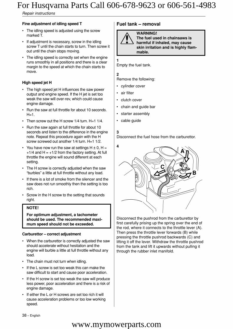
3Disconnect the fuel hose from the carburettor.
4
Fuel tank – removal
WARNING!The fuel used in chainsaws isharmful if inhaled, may causeskin irritation and is highly flam-mable.
Disconnect the pushrod from the carburettor byfirst carefully prising up the spring over the end ofthe rod, where it connects to the throttle lever (A).Then press the throttle lever forwards (B) whilepressing the throttle pushrod backwards (C) andlifting it off the lever. Withdraw the throttle pushrodfrom the tank and lift it upwards without pulling itthrough the rubber inlet manifold.
C
A
B
Repair instructions
Fine adjustment of idling speed T
• The idling speed is adjusted using the screwmarked T.
• If adjustment is necessary, screw in the idlingscrew T until the chain starts to turn. Then screw itout until the chain stops moving.
• The idling speed is correctly set when the engineruns smoothly in all positions and there is a clearmargin to the speed at which the chain starts tomove.
High speed jet H
• The high speed jet H influences the saw poweroutput and engine speed. If the H jet is set tooweak the saw will over-rev, which could causeengine damage.
• Run the saw at full throttle for about 10 seconds.H=1.
• Then screw out the H screw 1/4 turn. H=1 1/4.
• Run the saw again at full throttle for about 10seconds and listen to the difference in the enginenote. Repeat this procedure again with the Hscrew screwed out another 1/4 turn. H=1 1/2.
• You have now run the saw at settings H ± 0, H =+1/4 and H = +1/2 from the factory setting. At fullthrottle the engine will sound different at eachsetting.
• The H screw is correctly adjusted when the saw“burbles” a little at full throttle without any load.
• If there is a lot of smoke from the silencer and thesaw does not run smoothly then the setting is toorich.
• Screw in the H screw to the setting that soundsright.
NOTE!
For optimum adjustment, a tachometershould be used. The recommended maxi-mum speed should not be exceeded.
Carburettor – correct adjustment
• When the carburettor is correctly adjusted the sawshould accelerate without hesitation and theengine will burble a little at full throttle without anyload.
• The chain must not turn when idling.
• If the L screw is set too weak this can make thesaw difficult to start and cause poor acceleration.
• If the H screw is set too weak the saw will produceless power, poor acceleration and there is a risk ofengine damage.
• If either the L or H screws are set too rich it willcause acceleration problems or too low workingspeed.
For Husqvarna Parts Call 606-678-9623 or 606-561-4983
www.mymowerparts.com
English – 39
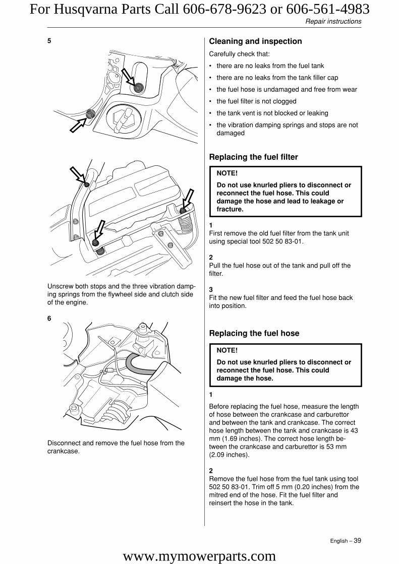
5
Unscrew both stops and the three vibration damp-ing springs from the flywheel side and clutch sideof the engine.
6
Disconnect and remove the fuel hose from thecrankcase.
Repair instructions
Cleaning and inspection
Carefully check that:
• there are no leaks from the fuel tank
• there are no leaks from the tank filler cap
• the fuel hose is undamaged and free from wear
• the fuel filter is not clogged
• the tank vent is not blocked or leaking
• the vibration damping springs and stops are notdamaged
Replacing the fuel hose
1
Before replacing the fuel hose, measure the lengthof hose between the crankcase and carburettorand between the tank and crankcase. The correcthose length between the tank and crankcase is 43mm (1.69 inches). The correct hose length be-tween the crankcase and carburettor is 53 mm(2.09 inches).
2Remove the fuel hose from the fuel tank using tool502 50 83-01. Trim off 5 mm (0.20 inches) from themitred end of the hose. Fit the fuel filter andreinsert the hose in the tank.
NOTE!
Do not use knurled pliers to disconnect orreconnect the fuel hose. This coulddamage the hose.
Replacing the fuel filter
1First remove the old fuel filter from the tank unitusing special tool 502 50 83-01.
2Pull the fuel hose out of the tank and pull off thefilter.
3Fit the new fuel filter and feed the fuel hose backinto position.
NOTE!
Do not use knurled pliers to disconnect orreconnect the fuel hose. This coulddamage the hose and lead to leakage orfracture.
For Husqvarna Parts Call 606-678-9623 or 606-561-4983
www.mymowerparts.com
40 – English
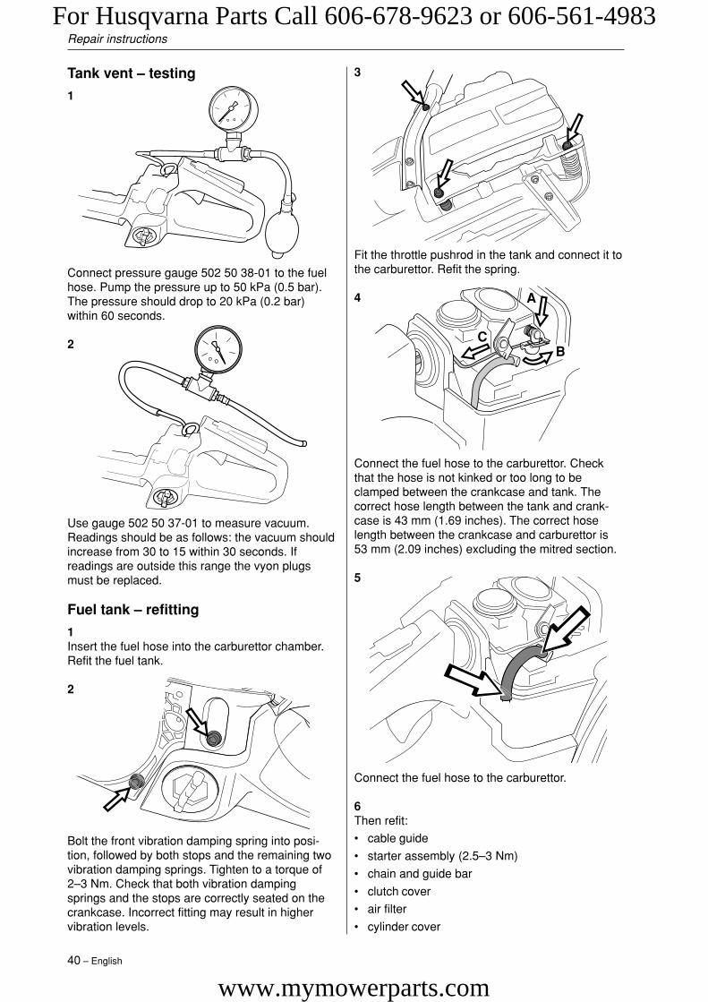
Connect the fuel hose to the carburettor. Checkthat the hose is not kinked or too long to beclamped between the crankcase and tank. Thecorrect hose length between the tank and crank-case is 43 mm (1.69 inches). The correct hoselength between the crankcase and carburettor is53 mm (2.09 inches) excluding the mitred section.
5
Fit the throttle pushrod in the tank and connect it tothe carburettor. Refit the spring.
4
Connect the fuel hose to the carburettor.
6Then refit:
• cable guide
• starter assembly (2.5–3 Nm)
• chain and guide bar
• clutch cover
• air filter
• cylinder cover
3
C
A
B
Repair instructions
Bolt the front vibration damping spring into posi-tion, followed by both stops and the remaining twovibration damping springs. Tighten to a torque of2–3 Nm. Check that both vibration dampingsprings and the stops are correctly seated on thecrankcase. Incorrect fitting may result in highervibration levels.
Connect pressure gauge 502 50 38-01 to the fuelhose. Pump the pressure up to 50 kPa (0.5 bar).The pressure should drop to 20 kPa (0.2 bar)within 60 seconds.
2
Tank vent – testing
1
Use gauge 502 50 37-01 to measure vacuum.Readings should be as follows: the vacuum shouldincrease from 30 to 15 within 30 seconds. Ifreadings are outside this range the vyon plugsmust be replaced.
Fuel tank – refitting
1Insert the fuel hose into the carburettor chamber.Refit the fuel tank.
2
For Husqvarna Parts Call 606-678-9623 or 606-561-4983
www.mymowerparts.com

English – 41
Repair instructions
Undo the four cylinder bolts and lift the cylinder offcarefully.
Models 340, 345
Piston and cylinder – removal
1Remove:
• cylinder cover
• carburettor (see “Carburettor – removal”)
• silencer
• spark plug
• fuel tank (applies to 340, 345)
2
Unbolt the vibration damping spring from the handgrip.
3
Undo the four cylinder bolts from the undersideand lift the cylinder off carefully.
Remove the circlips from the ends of the gudgeonpin and press it out. Then lift off the piston.
6
If replacing the cylinder:Unscrew the decompression valve. Remove theintake system, see “Air intake system – removal”.
Remove the bearing from the little end of theconnecting rod.
7
4Cover the opening in the crankcase.
5
For Husqvarna Parts Call 606-678-9623 or 606-561-4983
www.mymowerparts.com
42 – English
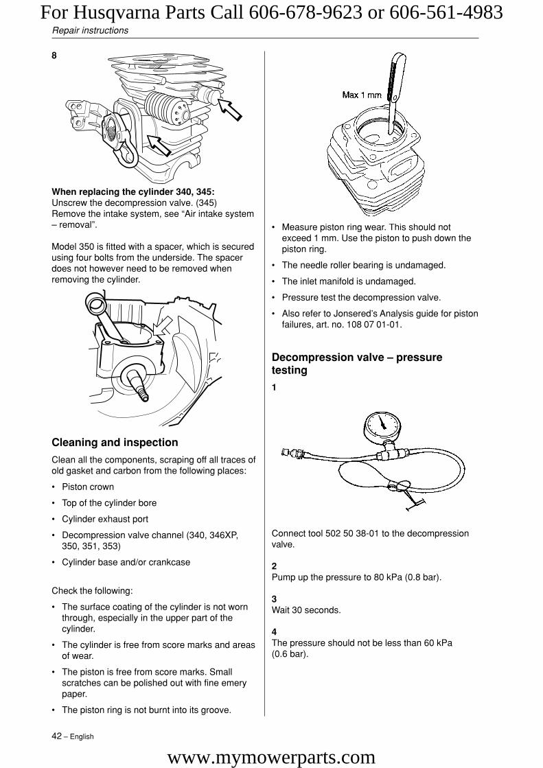
• Measure piston ring wear. This should notexceed 1 mm. Use the piston to push down thepiston ring.
• The needle roller bearing is undamaged.
• The inlet manifold is undamaged.
• Pressure test the decompression valve.
• Also refer to Jonsered’s Analysis guide for pistonfailures, art. no. 108 07 01-01.
Decompression valve – pressuretesting
1
Connect tool 502 50 38-01 to the decompressionvalve.
2Pump up the pressure to 80 kPa (0.8 bar).
3Wait 30 seconds.
4The pressure should not be less than 60 kPa(0.6 bar).
Repair instructions
8
When replacing the cylinder 340, 345:Unscrew the decompression valve. (345)Remove the intake system, see “Air intake system– removal”.
Model 350 is fitted with a spacer, which is securedusing four bolts from the underside. The spacerdoes not however need to be removed whenremoving the cylinder.
Cleaning and inspection
Clean all the components, scraping off all traces ofold gasket and carbon from the following places:
• Piston crown
• Top of the cylinder bore
• Cylinder exhaust port
• Decompression valve channel (340, 346XP,350, 351, 353)
• Cylinder base and/or crankcase
Check the following:
• The surface coating of the cylinder is not wornthrough, especially in the upper part of thecylinder.
• The cylinder is free from score marks and areasof wear.
• The piston is free from score marks. Smallscratches can be polished out with fine emerypaper.
• The piston ring is not burnt into its groove.
For Husqvarna Parts Call 606-678-9623 or 606-561-4983
www.mymowerparts.com

English – 43
Repair instructions
Piston and cylinder – refitting 346XP,350, 351, 353
1
Fit the piston with the arrow pointing towards theexhaust port. Push in the gudgeon pin and fit thecirclips. If replacing the cylinder, fit the decompres-sion valve, tightening to a torque of 12–14 Nm.
3
Lubricate the little end bearing with two-stroke oiland insert it in the connecting rod.
2
Fit the inlet manifold 503 86 63-01 to the cylinder.Check that the impulse tube is correctly seated inthe impulse channel.
NOTE!
It is very important that there are no leaksin the inlet system, otherwise the enginemay seize.
Press the insulating plate 503 86 62-01 onto thecylinder. Check that the impulse tube connected tothe insulating plate is seated correctly in the inletmanifold and lock the clamp over the manifold.
5Lubricate the piston ring and piston with two-strokeoil.
6
4
Fit a new cylinder base gasket. Compress thepiston ring with tool 502 50 70-01 and lower thecylinder over it carefully.
7
1
23
4
Fit the cylinder bolts, tightening them in diagonalpairs to a torque of 8–10 Nm.
For Husqvarna Parts Call 606-678-9623 or 606-561-4983
www.mymowerparts.com

44 – English
NOTE!
If a new piston or cylinder has been fittedthe saw must be run for the first 3–4hours with carburettor adjusted to thefactory settings.
Piston and cylinder – refitting 340, 345
1-5See Piston and cylinder 346XP, 350, 351, 353 –Refitting points 1-5.
6Apply silicone adhesive/sealing compound (03-7062) to the crankcase’s contact surfaces with thecylinder.Carefully slide the cylinder down over the pistontowards the big end bearing.
Note!Work is facilitated if the crankshaft complete withbearing and piston is released from the crankcaseand the piston is pushed into the cylinder. The unitis then refitted in the crankcase.
7
Fit the cylinder bolts, tightening crosswise to atorque of 13–15 Nm.
8Pressure test the cylinder.
9Refit:
• spark plug, tighten to a torque of 15 Nm
• carburettor, see “Carburettor – refitting”,
• silencer, tighten to a torque of 8–10 Nm
• cylinder cover
• Loosen the carburettor bolts so that the carbu-rettor can be moved back about 4 mm. Insertcover plate 502 54 11-02 between the carburet-tor and the carburettor flange. Tighten thecarburettor bolts to a torque of 1–1.5 Nm.
• Loosen the silencer bolts so that the silencercan be moved back about 4 mm. Insert coverplate 502 54 11-02 between the silencer and theexhaust flange on the cylinder flange. Tightenthe silencer bolts to a torque of 8–10 Nm.
• Unscrew and remove the spark plug. Screw inpressure test nipple 503 84 40-02. Connect tool502 50 38-01 to the nipple. The decompressionvalve must be closed. The decompression valvemust be closed. To check the decompressionvalve itself, see “Decompression valve – pres-sure testing”.
• Pump up the pressure to 80 kPa (0.8 bar).
• Wait 30 seconds.
• The pressure should not be less than 60 kPa(0.6 bar).
• Remove the cover plates from the silencer andcarburettor, tighten the bolts to the specifiedtorque. Remove the pressure test nipple 503 8440-02 and refit the spark plug.
WARNING!After pressure testing the cylin-der, check that the inlet manifoldis seated correctly, otherwise thesaw may be damaged.
Cylinder – pressure testing
Repair instructions
For Husqvarna Parts Call 606-678-9623 or 606-561-4983
www.mymowerparts.com
English – 45
Repair instructions
Crankcase and crankshaft –dismantling 346XP, 351, 353
1Remove the following:
• guide bar and chain
• clutch cover
• cylinder cover
• starter assembly*
• ignition system*
• generator*
• centrifugal clutch*
• oil pump*
• bark rest
• chain tensioner
• throttle pushrod
• carburettor*
• carburettor base
• silencer*
• piston and cylinder*
• fuel tank*
* See special instructions.
NOTE!
Take care to prevent dirt or foreign parti-cles getting into the bearings.
2
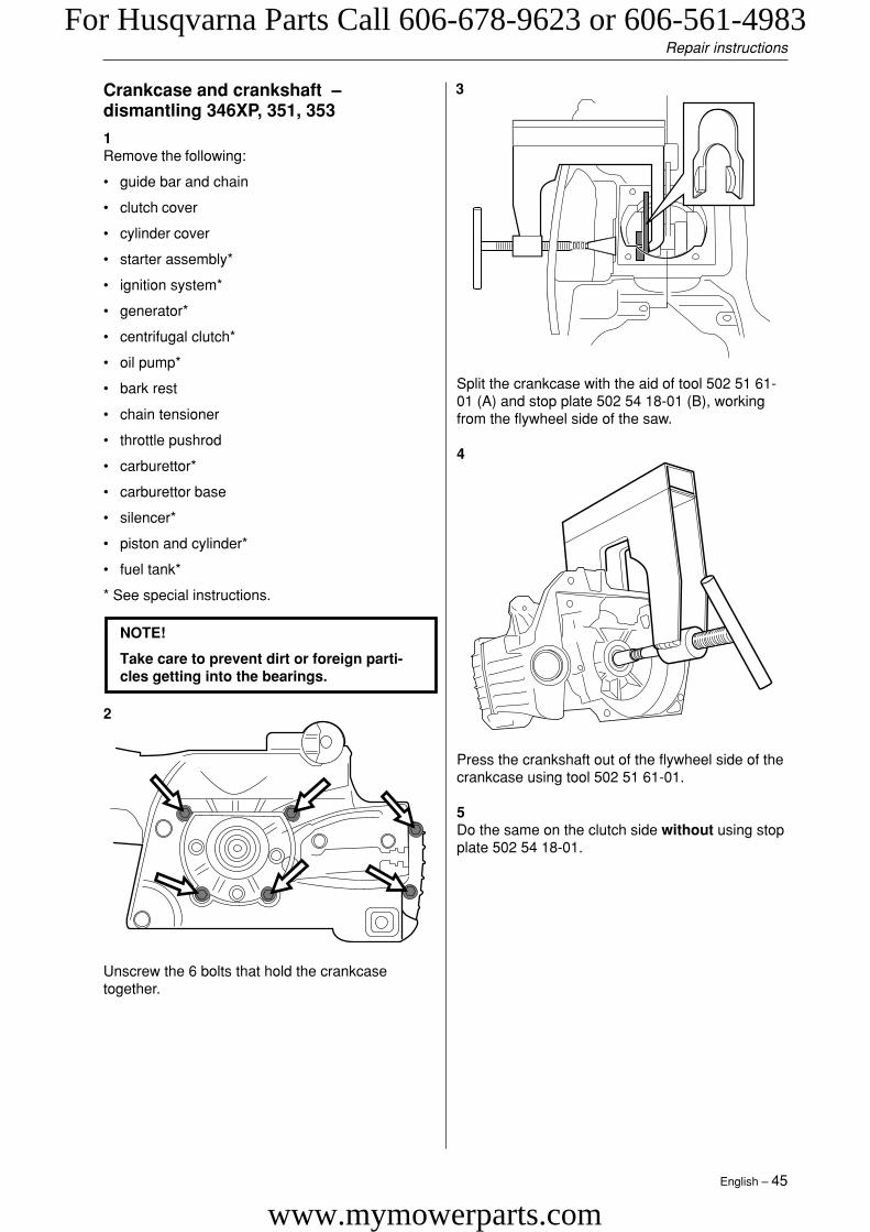
Unscrew the 6 bolts that hold the crankcasetogether.
3
Split the crankcase with the aid of tool 502 51 61-01 (A) and stop plate 502 54 18-01 (B), workingfrom the flywheel side of the saw.
4
Press the crankshaft out of the flywheel side of thecrankcase using tool 502 51 61-01.
5Do the same on the clutch side without using stopplate 502 54 18-01.
For Husqvarna Parts Call 606-678-9623 or 606-561-4983
www.mymowerparts.com

46 – English
Crankshaft bearings – replacement346XP, 351, 353
If the crankshaft bearings are to be replaced, tapthem out gently using drift 502 70 84-01.
The new bearings must be shrunk-fit into thecrankcase using a hot air gun.
Cleaning and inspection
Clean and inspect all parts carefully.
Sealing ring – replacement
Remove the sealing ring from the magnet sideusing tool 502 50 55-01.
Sealing ring replacement - drive side
Remove the oil pump.
1
Pry up the sealing ring from the bearing by using asmall screwdriver or the like.Note. The sealing ring can be replaced without theneed of removing the bearing.
2Press the new sealing ring into the bearing.
Repair instructions
Crankshaft complete - dismantling340, 345, 350
1Remove the following:
• chain and bar
• clutch cover
• cylinder cover
• starter assembly*
• ignition system*
• generator
• centrifugal clutch*
• throttle pushrod
• carburettor*
• silencer*
• piston and cylinder*
• fuel tank*
* See special instructions.
2
Lift the crankshaft completely out of the crankcase.
350:Unbolt the four bolts from underneath and lift offthe spacer.Lift the crankshaft completely out of the crankcase.
For Husqvarna Parts Call 606-678-9623 or 606-561-4983
www.mymowerparts.com

English – 47
Repair instructions
Cleaning and inspection
Clean and inspect all parts carefully.
Sealing ring – replacement
Remove the sealing ring from the crankcase usinga small screwdriver.
NOTE!
Take care to avoid damaging the crank-case.
To fit the sealing ring use the sleeve that is sup-plied with 502 50 30-16.The end with the half moon is used for the sealingring on the clutch side, which must be fitted flushwith the surface of the crankcase.The other end of the sleeve is used to fit thesealing ring on the flywheel side and ensures thatthe sleeve is fitted at the correct depth, 1.8 mm.Lubricate the sealing rings with oil.
Crankshaft bearings 340, 345, 350 –replacement
Remove:
• The crankshaft complete from the crankcase,see page 47.
1Pull off the crankshaft bearing from crankshaft.
2Fit a new bearing on the crankshaft.
Crankcase and crankshaft –reassembly 346XP, 351, 353
1
Hold the clutch side of the crankcase in a vice. Pullthe crankshaft into its bearing using assembly tools502 70 84-01 and 502 70 45-07.
2
Check that the guide pins are in place. Fit a newgasket to the mating surface of the clutch side ofthe crankcase.
3
Place the flywheel side of the crankcase over thecrankshaft and pull the two crankcase halvestogether using assembly tools 502 70 84-01 and502 70 45-06.
For Husqvarna Parts Call 606-678-9623 or 606-561-4983
www.mymowerparts.com

48 – English
4
Fit and tighten the six crankcase bolts to a torqueof 8–10 Nm. Check that the crankshaft rotatesfreely.
5Refit the following parts:
• bark rest
• oil pump*
• chain tensioner
• centrifugal clutch*
• fuel tank*
• piston and cylinder*
• generator*
• carburettor base
• carburettor*
• throttle pushrod
• silencer*
• ignition system*
• starter assembly*
• cylinder cover
• clutch cover
• guide bar and chain
* See special instructions.
NOTE!
If a new crankshaft has been fitted thesaw must be run in for 3-4 hours with thecarburettor adjusted to the factory set-tings.
Crankshaft complete 340, 345, 350 –reassembly
1Fit the crankshaft complete in the crankcase.
350:Fit and tighten the four bolts holding the spacerfrom underneath and fit the crankshaft complete inthe crankcase.
Refit the following parts:
• piston and cylinder*
• fuel tank*
• silencer*
• carburettor*
• throttle pushrod
• centrifugal clutch*
• generator*
• ignition system*
• starter assembly*
• cylinder cover
• clutch cover
• chain and bar
* See special instructions.
Repair instructions
For Husqvarna Parts Call 606-678-9623 or 606-561-4983
www.mymowerparts.com
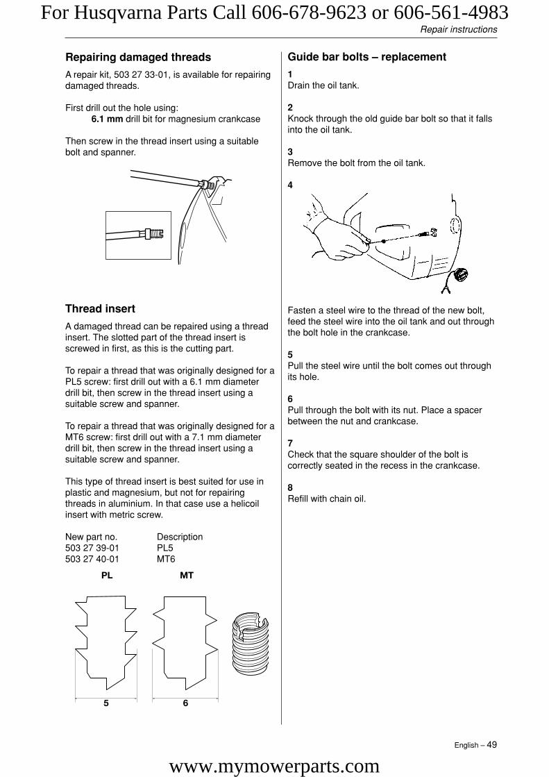
English – 49
Repair instructions
Repairing damaged threads
A repair kit, 503 27 33-01, is available for repairingdamaged threads.
First drill out the hole using:6.1 mm drill bit for magnesium crankcase
Then screw in the thread insert using a suitablebolt and spanner.
Thread insert
A damaged thread can be repaired using a threadinsert. The slotted part of the thread insert isscrewed in first, as this is the cutting part.
To repair a thread that was originally designed for aPL5 screw: first drill out with a 6.1 mm diameterdrill bit, then screw in the thread insert using asuitable screw and spanner.
To repair a thread that was originally designed for aMT6 screw: first drill out with a 7.1 mm diameterdrill bit, then screw in the thread insert using asuitable screw and spanner.
This type of thread insert is best suited for use inplastic and magnesium, but not for repairingthreads in aluminium. In that case use a helicoilinsert with metric screw.
New part no. Description503 27 39-01 PL5503 27 40-01 MT6
Guide bar bolts – replacement
1Drain the oil tank.
2Knock through the old guide bar bolt so that it fallsinto the oil tank.
3Remove the bolt from the oil tank.
4
Fasten a steel wire to the thread of the new bolt,feed the steel wire into the oil tank and out throughthe bolt hole in the crankcase.
5Pull the steel wire until the bolt comes out throughits hole.
6Pull through the bolt with its nut. Place a spacerbetween the nut and crankcase.
7Check that the square shoulder of the bolt iscorrectly seated in the recess in the crankcase.
8Refill with chain oil.
For Husqvarna Parts Call 606-678-9623 or 606-561-4983
www.mymowerparts.com
50 – English
Appendix A
Repair instructions
Basic adjustment for EPA II carburetorsAfter replacing the carburetor or high speed and/or lowspeed needle on an EPA (The US EnvironmentalProtection Agency) certified product a basic adjustmentmust be carried out as described below in order to meetthe EPA-requirements. This to achieve as low emissionsas possible. This instruction is made for USA & Canadaonly. On EPA carburetors both the H- and L-needles arefitted with caps to prevent the chain saw operator fromchanging the adjustment above EPA standard. The capscan be removed to achieve richer or leaner adjustments.To set the needles correctly an adjustment sleeve is fittedfrom the factory over the caps to lock them in maximumallowed settings.
When correctly set the caps must be fixed on the nee-dles. The adjustment sleeve then can be removed. Overthe caps on complete sparepart carburetor, there is aplastic sleeve which is intended to lock the caps at therichest position (anticlockwise towards stop) during thetime that the needles are adjusted. When the adjustmentis complete and the caps have been fixed on the nee-dles, the sleeve is no longer of any function and can beremoved.
NOTE! On the complete spare part carburetor, the L-needle is adjusted from the factory.
NOTE! Before making any adjustments the followingmust be done!
• Mount, for this model, approved bar & chain combina-tion (See Technical data in the Operator’s manual).
Model340/345/350 16”346XP/351 16”
• The chain should not be tensioned more than that itremains ~0,2 inches to the bar.
• Mount a new air filter.
Replacement of the H-needle or complete carburetor1. Screw the new H-needle to the bottom and turn it
counterclockwise ”A” turns.
Model340/345/350 A = 3/4346XP/351 A = 3/4
2. Check that:The H-cap is adjusted to its richest setting. (Turnedcounterclockwise to stop). The cap is not fixed to theneedle, it should rotate independently. Adjust the L-capto a center position (1/4 turn counterclockwise =minimum, 1/4 turn clockwise = maximum).
3. Start the engine. If necessary, adjust the idling speedwith the T-screw until the chain stops.
4. Adjust the H-needle to give a top speed of ”B” rpm.
Model340/345/350/351 B = 12 000346XP B = 13 000
Use a narrow blade screwdriver (Ref.no. 531 00 48-63)and insert it through the hole in the cap (max. blade width2 mm/0.08 inch).
5. Let the engine run at ”B” rpm ~ 1 minute, until warm.
6. Adjust the H-needle to a top speed of ”C” rpm.
Model340/345/350/351 C = 13 700346XP C = 14 300
7. Check that the H-cap is still adjusted to its richestsetting. (Turned counterclockwise to stop). NOTE!The H-needle must not rotate!
8. Gently knock the H-cap into position. Use a 5 mm/0.2inch mandrel (for ex. the locking pin for the bevel gearref.no. 502 02 61-03). This is a basic carburetoradjustment. Further fine adjustments, within the limitsthe caps allow, may be necessary to achieve optimumperformance. See the Operator’s manual.
Replacement of the L-needle1. Take off the cap from the L-needle using e.g. a pair of
cutting pliers and unscrew the needle.
2. Screw the new L-needle to the bottom and then turn itcounterclockwise ”D” turns.
Model340/345/350 D = 1 1/2346XP/351 D = 1 1/2
3. Press a new L-cap on the L-needle to the first stop,which means that the cap is not fixed to the needle, itshould rotate independently.
4. Adjust the L-cap to the richest position (turnedcounterclockwise to stop) without turning the needle.
5. Let the engine run at ~ ”E” app.1 minute until warmand then let it run on idle.
Model340/345/350/351 E = 12 000346XP E = 13 000
6. Adjust the idle speed to ”F” rpm.
Model340/345/350 F = 2 700346XP/351 F = 2 700
7. Adjust the L- needle until the highest possible idlingspeed is achieved and then turn theL-needle 1/2 turn counterclockwise. Use a narrowblade screwdriver w. ref.no. 531 00 48-63 and insertthrough the hole in the cap (max. blade width 2 mm/0.08 inch) .
NOTE! If the chain rotates, turn the idling speedscrew (T) counterclockwise until the chain stops.
8. Check that the L-cap is still adjusted to its richestposition. (Turned counterclockwise to stop).
NOTE! The L-needle must not rotate!
9. Gently knock the L-cap into position. Use a 5 mm/0.2inch mandrel (for ex. the locking pin for the bevel gearref.no. 502 02 61-03).
This is a basic carburetor adjustment. Further fineadjustments, within the limits the caps allow, may benecessary to achieve optimum performance. See theOperator’s manual.
For Husqvarna Parts Call 606-678-9623 or 606-561-4983
www.mymowerparts.com

English – 51
2003W12
114 01 47-26
For Husqvarna Parts Call 606-678-9623 or 606-561-4983
www.mymowerparts.com