
Workshop Manual 325HE3 325HE4 - redmax.com
76
Workshop Manual English 325HE3 325HE4
Transcript of Workshop Manual 325HE3 325HE4 - redmax.com

Workshop Manual
English
325HE3 325HE4


English - 3
Workshop Manual
Contents
Contents
Husqvarna AB has a policy of continuous product development and therefore reserves the right to modify the design and appearance of products without prior notice.
Index ..................................................................... 4Introduction and safety instructions ...................... 6Technical data ........................................................ 10Engine special tools .............................................. 12Service data .......................................................... 15Safety equipment .................................................. 20Repair instructions ................................................. 24Troubleshooting ..................................................... 69

4 - English
Index
A
Angle adjustment of cutting deck ........................ 66Air filter, dismantling and assembling ................. 32Air purge ............................................................. 33
B
Bevel gear ........................................................... 62, 62
C
Carburetor .......................................................... 33Carburetor, dismantling ...................................... 35Carburetor, assembling ...................................... 38Carburetor, settings ............................................ 40Centrifugal clutch, dismantling............................ 42Centrifugal clutch, assembling ............................ 44 Clutch drum, replacing........................................ 58Clutch drum, dismantling and assmebling .......... 58Crankshaft, dismantling ...................................... 55Crankcase, dismantling ...................................... 55Crankshaft, assembling ...................................... 57Crankcase, assembling ...................................... 57 Cylinder and piston, dismantling ................... 45 Inspection ...................................................... 47 Analysis and actions ...................................... 47Cutting deck, dismantling ................................... 62, 63, 64Cylinder and piston, assembling ......................... 54Cutting deck, assembly ...................................... 65 , 66
F
Flywheel, dismantling ......................................... 42Flywheel, assembling ......................................... 44Fuel system ........................................................ 32Fuel filter ............................................................. 33
G
Gear box ............................................................. 61Grease nipple ..................................................... 68
H
Hook shaft and lever, dismantling ....................... 61Hook shaft and lever, assembling ....................... 68
I
Introduction and safety instructions .................... 7Ignition module, adjusting ................................... 31Ignition module, dismantling ............................... 42Ignition module, assembling ............................... 44Ignition spark, checking ...................................... 28
M
Muffler, dismantling............................................. 21Muffler, Assembling ............................................ 21
P
Piston, dismantling ............................................. 45Piston, assembling ............................................. 54
S
Service data ....................................................... 15Shaft ................................................................... 64Separate gear box from shaft ............................. 61Special tools ....................................................... 13Starter recoil pulley, dismantling ......................... 25Starter recoil pulley, assembling ......................... 25Start pawls, replacing ......................................... 27 Stop switch, dismantling ..................................... 21Stop switch, assembling ..................................... 21Stop switch, resistance test ............................... 22Symbols in the Workshop Manual ...................... 9Symbols on the machine .................................... 9
T
Tank Venting ....................................................... 32Technical data ..................................................... 10Throttle, dismantling ........................................... 22Throttle, assembling ........................................... 23Troubleshooting .................................................. 69 Engine does not start .................................... 70 Engine is difficult to stop ................................ 71 Engine stops working during operation ......... 71 Insufficient output or unstable rotation........... 72 Other Engine problems.................................. 73

English - 5
Index

6 - English
Introduction and safety instructions
2 Introduction and safety instructions
Contents2.1 General ...........................................................................................................................72.2 Safety .............................................................................................................................72.3 Target group ....................................................................................................................72.4 Modifications ....................................................................................................................72.5 Tools ...............................................................................................................................72.6 Structure .........................................................................................................................72.7 Numbering ......................................................................................................................72.8 General instructions ........................................................................................................82.9 Special instructions ........................................................................................................82.10 Symbols on the machine ................................................................................................92.11 Symbols in the Workshop Manual ..................................................................................9

English - 7
2 Introduction and safety instructions
Introduction and safety instructions
2.1 GeneralThis Workshop Manual describes in detail how to be troubleshoot, repair and test the machine. A description of different safety steps that must be taken during repair work is also given.
2.2 SafetyNote: The section dealing with safety must be read and understood by all those carrying out repair work or service on the trimmer/brushcutter.
Warning symbols can be found in this Workshop Manual and on the machine. See “Symbols on the machine” and “Symbols in the Workshop Manual”. A new warning symbol decal must be applied as soon as possible if a warning symbol on the product has been damaged or is missing so that the greatest level of safety can be maintained when using the machine.
2.3 Target groupThis Workshop Manual is written for personnel who are assumed to have general knowledge of repair-ing and servicing the machine.
The Workshop Manual must be read and under-stood by personnel who will carry out repair work and service on the machine. The Manual is also suitable for use when training new employees.
2.4 ModificationsAny modifications to the machine will be gradually introduced into ongoing production. As these modifications affect service and/or spare parts, specific service information will be sent out on each occasion. This means that in time this Workshop Manual will become out of date. In order to prevent this, the Manual should be read together with all service information concerning the machine in question.
2.5 ToolsSpecial tools are required for some stages. All service tools are listed in the Workshop Manual. Usage is made apparent in each section.
Always use Husqvarna’s original:• Spare parts• Service tools• Accessories
2.6 StructureThis Workshop Manual can be used in two different ways:
• Repair of a specific system on the machine.• Dismantling and assembly of the entire machine.
Repair of a specific systemWhen a particular system on the machine is to be repaired, proceed as follows:
1. Look up the page for the system in question.
2. Carry out the following steps:
Dismantling Cleaning and inspection Assembly
2.7 NumberingPosition references to components inside the figures are designated A, B, etc.The figures are numbered 1, 2 etc.The position references and figure numbers restart in each new section.

8 - English
2.8 General InstructionsThe workshop where the machine is to be repaired must be equipped with safety equipment in accord-ance with local regulations.
No one may repair the machine unless they have read and understood the content of this Workshop Manual.
This workshop manual contains the following warning boxes in relevant places.
2.9 Special Instructions
The fuel used in the machine has the following hazardous properties:• The fluid and its vapour are poisonous.• Can cause eye and skin irritation.• Can cause breathing problems.• Is highly inflammable.• Running an engine in a confined or badly ventila-
ted area can result in death due to asphyxiation or carbon monoxide poisoning.
• Use protective gloves and eye protection, gogg-les must comply with the ANSI Z87.1 for US or EN166 for EU contries.
When using compressed air, do not direct the jet towards your body. Air can penetrate into the blood stream, which can endanger life.
Wear protective earplugs or earmuffs when test running.
After test running, do not touch the muffler until it has cooled down. Risk of burns. Use protective gloves when working with the muffler.
Exercise care to ensure the starter spring does not fly out and cause personal injury. Wear protective glasses. If the spring tension is activated on the starter pulley when it is to be taken up, the spring can fly out and cause personal injury.
Keep in mind the fire risk. The machine may emit sparks, which cause ignition.
WARNING!The warning box warns of the risk of personal injury if the instruc-tions are not followed.
NOTE!
This box warns of material damage if the instructions are not followed.
Introduction and safety instructions

English - 9
Introduction and safety instructions
2.10 Symbols on the machineThe symbols below are embedded on the machine
Choke control
Refuelling
Stop switch
Air purge
2.11 Symbols in the Workshop Manual
This symbol warns of personal injury when the instructions are not followed.
Use protective gloves.
Use protective goggles.

10 - English
Technical data
3 Technical data
Displacement Cylinder diameter Stroke length Max. output/speed cm3/cubic inch Ø mm/Ø inch mm/inch kW/rpm
325HE3: 25,4/ 1,55 34 / 1.34 28 / 1,10 1,0 / 8500325HE4: 25,4/ 1,55 34 / 1.34 28 / 1,10 1,0 / 8500
Electrode gap Ignition system Air gap Carburetor type mm/inch mm/inch
325HE3: 0,65/0.025 IKEDA UK-08934-505 0,3/0.012 Walbro WTEA-8C325HE4: 0,65/0,026 IKEDA UK-08934-505 0,3/0,012 Walbro WTEA-8C

English - 11
3 Technical data
Technical data
Engage speed Spark plug Volume fuel tank rpm Litre/US. pint
325HE3: 4000 (+/- 200) NGK BPMR8Y 0,51/1,08 325HE4: 4000 (+/- 200) NGK BPMR8Y 0,51/1,08
Weight without fuel kg / lbs
325HE3: 6,3/13,9 325HE4: 6,4/14,1

12 - English
Engine special tools
4 Engine special tools
Contents4.1 Special tools ...................................................................................................................13

English - 13
Engine special tools
34
2
Removal bolt M6
1
78
For shaft (open)
9
10
4.1 Special tools
11
65

14 - English
Engine special tools
13
14
12
Pos Description Used for Order No.
1 Torx wrench General disassembly / assembly tasks 578 28 90-01
2 Air gap tool (t 0.3mm) Adjust the air gap when installing the ignition module
514 22 10-01
3 Stopper (14 mm use) Fix piston in place when installing / removing clutch, rotor and starter pulley.
514 24 39-01
4 Puller assembly Removing the rotor (removal bolt M6) 510 13 89-01
5 Rod assembly Installing / removing the piston pin 513 18 12-01
6 Puller Installing / removing the recoil pulley 581 96 55-01
7 Plier Remove Clutch drum clip 515 41 95-01
8 Rod Remove clutch drum 581 44 10-01
9 Guide Installing clutch drum clip 581 44 11-01
10 Guide pusher Installing clutch drum clip 515 41 98-01
11 Hook for fuel filter Withdrawing the fuel filter 502 50 83-01
12 Adjustment screwdriver
Protractor
Adjustment of the carburetor
Adjustment of the carburetor
530 03 55-60
584 49 29-04
13 Assembly kit, piston Assembling the piston 502 50 70-01
14 Revolution counter Engine speed meter 502 71 14-01
Spark plug Testing spark plug 502 71 14-01
Pliers Ignition cable 502 50 06-01
Pressure test tool Pressure test in fuel system 531 03 06-23

English - 15
Service data
5 Service data
13
4,0
4,0
4,0
1,5
1,5
5,0
5,0
8,08,0
8,0
7,07,07,0
3,0
4,0
4,0
4,0
HE3 HE4
6,06,0
6,0
Lubricate with two-stroke oil.
Lubricate with Grease
Apply thread lock: Three bond or loctite
Tighten torque in Nm
Note!
Some of the screws are captive screws and will remian into the cover.

16 - English
Service data
4,04,018
7,0
10
1,0
7,0
4,0
6,0

English - 17
Service data
3,0
8,0
7,0
7,0
7,08,0
8,015,0
8,0
8,0
8,0
8,0

18 - English
Service data
5,0±1
5,0±1
3,5±1
2,0
10 ±1
5,0 ±1
5,0±1
2,0 ±1
5,0±1
5,0±1
4,0±1
4,0±1
5,0 ±1
3±1 *2
*2
*6

English - 19
Service data
9,0 ± 1
5,0 ± 1

20 - English
safety equipment
6 Safety equipment
Content
6.1 Dismantling the muffler .................................................................................................21
6.2 Assembling the muffler ..................................................................................................21
6.3 Dismantling the stop switch ...........................................................................................21
6.4 Assembling the stop switch ............................................................................................21
6.5 Resistance test - stop switch ..........................................................................................22
6.6 Dismantling throttle.........................................................................................................22
6.7 Assembling the throttle ...................................................................................................23

English - 21
Safety equipment
6.1 Dismantling the muffler
Remove the cover of the muffler.
Dismantle the two screws to the muffler. Also remove the gasket.
6.2 Assembling the muffler
Check the muffler, and if you find any deformation or cracks replace the muffler.
If the muffler is fitted with a spark arrestor mesh, put it in place first. Make sure the mesh is in the correct position, see illustration.
Before assembly the muffler remove carbon gently with a screwdriver.
Fit the gasket and the muffler Tighten the screws. Torque 10 Nm.
Warm up the engine and retighten the screws.
6.3 Dismantling the stop switch
Carefully remove the stop switch using a flat screwdriver or similar tool.
Disconnect the cables.
Clean and check the stop switch carefully. Parts must be replaced if cracked or show signs of other defects. Always use original spare parts.
6.4 Assembling the stop switch
Connect the cables to the stop switch. Fit the stop switch.

22 - English
Safety equipment
6.5 Resistance test - stop switchDismantle the stop switch as outlined.
Clean the contact areas.
test the resistance by connecting a multimeter to the stop switch. The resistance should be as fol-low:
”0” pressed in - less than 0.1 Ω.
”1” pressed in - more than 1000 Ω.
6.6 Dismantling ThrottleAssembly of the throttle is done in the reverse order as set out for dismantling.Position the parts in the left-hand throttle half.
Dismantle the clutch housing cover from engine body, see Dismantling the shaft from engine body.
Remove screw that holding the shaft, (A).Loosen the screws (B) holding the clamp around the shaft. Remove the shaft assembly from engine body and the throttle from the shaft.
Remove the screw (C) holding the shaft.Remove the 5 screws (D, E) holding the handle in place.
Carefully remove the right handle half and make sure that the anti vibration element (F) is not lost (one on each side of the clamping sleeve).
Note how the different parts are fitted.Remove the clamping sleeve (G).
Note how the throttle’s recoil spring (H) is fitted and remove the throttle lever.Remove the throttle trigger lock (J) and the anti vibration element (K).
A
B
D
CE
J
KH
FG

English - 23
Safety equipment
Check that the throttle cable is fitted to the under-side of the pin on the throttle trigger lock.
6.7 Assembling the throttlePut all details in the left half of the handle. Make sure that the spring is correct fitted. Make sure that all cables is fitted in the handle and will not be clamped.
Assemble the throttle trigger lock (A) and the anti vibration element (B).
Fit the spring (C) and the throttle lever.
Fit the clamping sleeve (D).
Carefully put the handle together, make sure the anti vibration element is not lost.
Fasten the 5 screws (E) that holding the handle in place. Fasten the screw (F) holding the shaft.
B
C
A
B
BD
F
E

24 - English
Startapparat
7 Repair instructions
Content
7.1 Dismantling the recoil pulley. ..........................................................................................25
7.2 Assembling the recoil pulley. ..........................................................................................257.3 Replacing the starter pawls ............................................................................................277.4 Checking the ignition spark ............................................................................................287.5 Dismantling the shaft and clutch housing from engine body ..........................................307.6 Assembling the shaft and clutch housing from engine body ..........................................307.7 Adjust the air gap when installing ignition module..........................................................317.8 Fuel system ....................................................................................................................327.9 Dismantling and assembling the air filter ........................................................................327.10 Tank venting ...................................................................................................................327.11 Replacing the fuel filter ...................................................................................................337.12 Air purge .........................................................................................................................337.13 Carburetor ......................................................................................................................337.14 Dismantling the carburetor .............................................................................................357.15 Assembling the carburetor .............................................................................................387.16 Carburetor settings .........................................................................................................407.17 Dismantling, centrifugal clutch, flywheel, ignition module ..............................................427.18 Assembling, centrifugal clutch, flywheel, ignition module ...............................................447.19 Dismantling the cylinder and piston................................................................................457.20 Cleaning, inspection .......................................................................................................477.21 Analysis and actions.......................................................................................................477.22 Assembling the piston and cylinder ................................................................................547.23 Dismantling, crankshaft and crankcase ..........................................................................557.24 Assembling, crankshaft and crankcase ..........................................................................577.25 Replacing the clutch drum and drive shaft .....................................................................587.26 Dismantling and assembling, clutch drum and drive shaft .............................................587.27 Dismantle lever and hook shaft ......................................................................................617.28 Separate gear box from shaft .........................................................................................617.29 Separate gear and cutting deck .....................................................................................627.30 Dismantling spiral bevel gear ........................................................................................627.31 Dismantling cutting deck house ......................................................................................637.32 Dismantling cutting deck ................................................................................................647.33 Assembly cutting deck ....................................................................................................657.34 Assembly cutting deck house .........................................................................................657.35 Assembly spiral bevel gear .............................................................................................667.36 Angle adjustment of the clamp connection.....................................................................667.37 Assembly lever and hook shaft .......................................................................................687.38 Grease nipple .................................................................................................................68

English - 25
7 Repair instructions
Repair instructions
7.1 Dismantling the recoil pulleyRemove the 3 screws and lift off the starter
Remove the inner cover in the starter housing. Use a flat screw driver or similar tool.
WARNING!Wear protective glasses. The return spring lies tensioned in the starter and can fly out and cause personal injury with careless handling..
Offload the spring tension.Lift up the starter cord on the starter pulley and allow it to rotate clockwise. Slow the rotation with your thumb.Remove the screw in the centre of the starter pulley. Carefully lift out the starter pulley from the starter housing.
7.2 Assembing the recoil pulleyClean component parts before assembling.Replace the return spring/starter pulley and starter cord, if necessary.
NOTE!The return spring and starter pulley are supplied pre-assembled and are fitted in the starter housing as a single unit.Exercise care when opening the packa-ging so that the spring does not fly out.

26 - English
Repair instructions
Lubricate the spindle with a little grease and fit the starter pulley. Tighten the screw.Assemble a new starter cord. Slide it into the starter pulley’s slot as illustrated and then out through the cord guide in the starter housing. Make sure the knot on the end of the cord is as small as possible!
NOTE!A new starter cord can be fitted without the need of dismantling the starter!
Assemble the starter handle.Tie a double knot and fold under the free end.Pull the knot fully into the handle.
Tension the return spring.Pull the starter cord out completely and slow the starter pulley with your thumb.Lift the cord into the notch on the starter pulley.Now turn the starter pulley counterclockwise, 6 turns.Check the spring tension. With the starter cord fully extended it should still be possible to turn the starter pulley further, at least a half turn.

English - 27
Repair instructions
7.3 Replacing the starter pawls
Fit the piston stop(A), no. 514 24 39-01 in the spark plug hole and loosen the starter pulley using special tool 581 96 55-01 (B).
Remove the circlip holdings the starter pawls.Lift out the starter pawls and spring for replace-ment.Assemble in the reverse order as set out for dismantling.
A
B

28 - English
7.4 Checking the ignition sparkDismantle the cylinder cover after the guard over the muffler and the air filter has been removed. Earth the spark plug on the cylinder and pull sharply on the start handle.A spark should be seen between the electrodes.If no spark is seen test with test spark plug no. 502 71 13-01.If a spark then occurs, the spark plug is faulty.Try a new spark plug.
If there is still no spark, remove the short-circuit cable from the stop switch.Prise up the switch by inserting a small screwdriver into the short end of the ignition switch.If the plug now sparks, the fault is either in the stop switch or the short-circuit cable.Change the switch as needed and check to see if the cable insulation is damaged.
Still no spark?Check the spark plug connection.Remove the spark plug cap and make sure the ignition cable is not damaged. Remove a segment of cable if required to get sufficient contact at the connection coil.
TIP!Spray the ignition cable with silicone to make it easier to pull off the spark plug cap.
When a part of the ignition cable has been cut off it helps to use pliers no. 502 50 06-01 to make a new hole in the ignition cable to fit the ignition coil.
NOTE!It is important that the tip of the contact coil hits the centre of the ignition lead to prevent sparking.
Repair instructions

English - 29
Fit the spark plug cap onto the ignition cable and make sure the ends of the wire is inserted into the centre of the spark plug cap for best contact.
TIP!Lubricate the hole in the spark plug guard using for instance silicon spray to make it easier to push the ignition coil in.
Still no spark?
Check other cables and connections for poor contacts (dirt, corrosion, cable breakage and damaged insulation).
Make sure that the cables are correctly drawn and lie in the cable grooves.
Do not forget to check the cables in the handle.
TIP!Use an Ohmmeter in order to easily check if cable breakage has occurred, due to pinching, for example.
Still no spark?Change ignition module. Disconnect the cables from the ignition module.Remove the two screws holding the ignition module.
Repair instructions

30 - English
Repair instructions
7.5 Dismantling the shaft and clutch housing from engine bodyRemove the cylinder cover, guard over the muffler, and the air filter.Unhook the throttle cable from the carburetor and insulator.
Disconnect the cables from ignition module.Remove the screws holding the clutch housing on the engine.Lift off the cover together with the shaft.
7.6 Assembling the shaft and clutch housing to the engine bodyPut the clutch housing on the engine. Fasten the screws to the engine body.Connect the cables from the ignition module. Do not pinch the cables.Fasten the screws holding the clutch cover.
AB
C
D

English - 31
Repair instructions
7.7 Adjust the air gap when installing the ignition module1
Adjust the air gap as needed to the correct value.• Loosenthebolts.• Positionthegaugetoadjustthegapandpress
the ignition module against the flywheel.• Tightentheboltsandchecktheairgapagain.If the spark plug still does not fire, the ignition system should be replaced.
Torque: 4.0 Nm.
Fig 5
A Rotor
B Gauge
C Ignition module
See Fig for Ignition module model (D) and Article No (E).
Engine Model
Ignition module
Module Resistance Value
525524
UK08934 505
Primary (IronCore⇔Primary Terminal):80 kΩ±20%
Secondary (IronCore⇔High-VoltageWire):4 kΩ±10%
Air Gap Gauge ModelNo.
0.3 mm 514 22 10-01
The stated resistance value is only a guideline figure when measuring with the tester. Internal leaks and the like are not detected, even if a resistance value is given. A gap tester is also available as a measurement component, as a spark tester for measuring the strength of sparking even during engine operation. Fig to the left is a 3-core gap tester.
AB
A
B
C

32 - English
Repair instructions
7.8 Fuel systemIn addition to the fuel tank and carburetor, the fuel system consists of the air filter, fuel filter and tank venting.
All these components interact so that the engine receives the optimal mixture of fuel and air to make it as efficient as possible. Very small deviations in the carburetor setting or a blocked air filter have a large effect on the running and efficiency of the engine.
The carburetor can come from several different manufacturers on our models, but the function and repair methods are essentially the same.
WARNING!Do not clean not the filter with petrol. Hazardous!
7. 9 Dismantling and assmbling the Air filterRemove the cover over the carburetor and lift off the air filter. The filter (A) is made of Urethan foam and must be cleaned with warm soapy water.The filter (B) is a Felt filter and must be cleaned with compressed air from the clean side to the drive side.A damaged filter should be replaced with a new filter.
Assembly the air filter in revers order.
7.10 Tank venting
Tank venting takes place through the fuel cap and needs to be functional for the engine to work.• Removethefuelhosefromthecarburetorand
empty the fuel from the tank.• Connectthefuelhosetopressuretesterno.
531 03 06-23.• Pumpupavacuumof50kPa(0.5bar)inthe
tank.• Thepressureshoulddropto20kPa(0.2bar)
or revert to atmospheric pressure within 45 seconds.
A
B

English - 33
Repair instructions
7.11 Replacing the fuel filterThe fuel hose in the tank contains a fuel filter. It is accessible through the fill hole. Pull out the filter with your fingers or with help of tool 502 50 83-01.
If the filter is not too dirty, its surface can be cleaned with a brush.Otherwise it must be replaced.Check the fuel hose for cracks and leaks.Make sure that the filter’s connection neck is inserted as far as possible into the fuel hose and that the clip is sufficiently tight so that the filter cannot slide off the tube.
7.12 Air purgeThe fuel pump has the task of facilitating the start of the engine when cold. The pump fills the carburetor with fuel before attempting to start the engine. This also prevents vapour bubbles from blocking the narrow fuel channels.
If the pump does not work it must be replaced.
Note how the fuel hoses are connected to simplify assembly.
7.13 Carburetor
1. Remove the air filter cover and blow the carbu-retor compartment clean with compressed air.
2. Disconnect the throttle cable from the lever arm on the carburetor and from the guide in the insulator.
3. Remove carburetor screws and the fuel pipe.4. Move the air filter housing to the side, remove
the fuel pipe and lift off the carburetor.
34 - English
Repair instructions
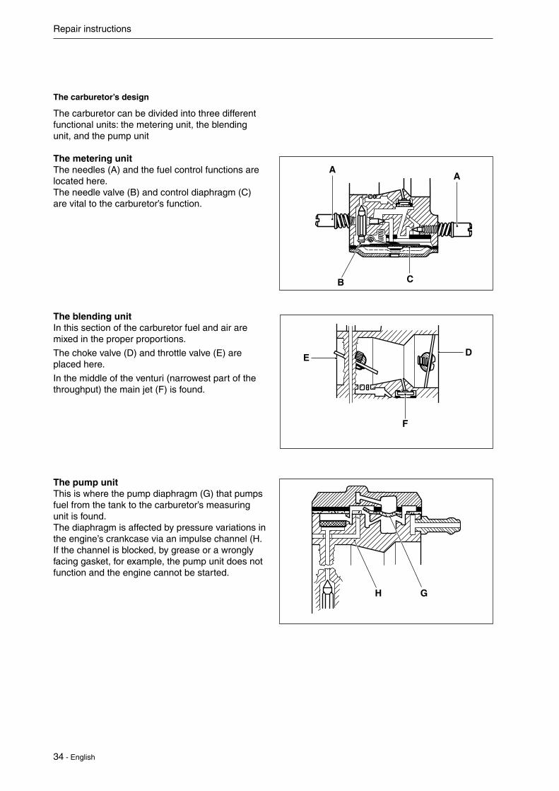
The carburetor’s design
The carburetor can be divided into three different functional units: the metering unit, the blending unit, and the pump unit
The metering unitThe needles (A) and the fuel control functions are located here.The needle valve (B) and control diaphragm (C) are vital to the carburetor’s function.
The blending unitIn this section of the carburetor fuel and air are mixed in the proper proportions.
The choke valve (D) and throttle valve (E) are placed here.
In the middle of the venturi (narrowest part of the throughput) the main jet (F) is found.
The pump unitThis is where the pump diaphragm (G) that pumps fuel from the tank to the carburetor’s measuring unit is found.The diaphragm is affected by pressure variations in the engine’s crankcase via an impulse channel (H.If the channel is blocked, by grease or a wrongly facing gasket, for example, the pump unit does not function and the engine cannot be started.
H G
DE
F
AA
B C

English - 35
Repair instructions
7.14 Dismantling the carburetorCarefully remove the metering diaphragm (A) and gasket (B).
Check the diaphragm for holes and wear on the pin (C).
Replace the diaphragm if required.
Connect pressure tester 531 03 06-23 to the fuel hose nipple.
Lower the carburetor in a vessel with petrol in order to discover any leaks more easily.
Test the pressure at 50 kPa.
No leakage is permitted.
In the event of leakage – remove the needle valve.Loosen the bolt and remove the lever arm, axle, needle valve and spring.
B
A
C

36 - English
Repair instructions
Check the needle valve for damage on the tip (D) and in the lever arm groove. (E)
Check the lever arm for damage to the groove (F) for the needle valve and wear on the mounting points towards the control diaphragm (G).
Replace damaged components with new ones.
Remove the bolt holding the cover over the pump diaphragm.
Lift off the cover (H), the gasket (J) and the dia-phragm (K).
Check the diaphragm for damage to the valve tongues. If the valve tongues are bent, the pump will not function in a satisfactory manner.
Hold it up to a light as well to discover any holes in the material.
Carefully remove the fuel screen (L), using a needle for example. Clean or replace the fuel screen.
NOTE!
During assembly the pump diaphragm should lie closest to the carburetor housing.
H
J
K
L
G
E
D
F

English - 37
Repair instructions
Unscrew the jet needles. Make sure they are clean and not damaged on the tip of the needle.
NOTE!Note how the jets are positioned.(For example, the H-needle is a little shorter than the L-needle).
Press out the main jet (A) with a suitable punch.
Remove the plug (B).
Carefully drill a small hole (Ø 2 mm) in the plug and pry it up with a pointed object or use special tool 531 03 01-91.
Remove the valves and springs. If these compo-nents are worn, idling is disrupted.Always replace the valves and springs at the same time.

38 - English
Repair instructions
7.15 Assembling the carburetor• Blowallchannelsinthecarburetorcompart-
ment clean• Mountanewplug(A). Use a suitable punch to get a completely tight
seal.• Pressinanewmainjet(B).
• Mountthevalvesandsprings.
Tip!
Any numbers on the valves should be able to be read from the outside.Make sure valves has a perfekt seal by locking at the edge of the valve with tha carburetor backlit, a light from the choke side.Also make sure there are no clearence between axial stop (e-clip in this case) and the carburetor housing.
Replace the fuel screen if it is damaged or cannot be cleaned.Place the pump diaphragm closest to the carburetor housing. Then the gasket and cover and the other components in reverse order of removal.
AB

English - 39
Repair instructions
Attach the various parts of the measuring unit in the reverse order as set out for dismantling.
The lever arm height should be 0,66 mm +-0,16 mm under carburetor housing plane.
Too high setting = too much fuel.
Too low setting = too little fuel.
Connect pressure tester 531 03 06-23 to the fuel intake on the carburetor.
Pump up the pressure to 50 kPa. Check for leaks.
If necessary lower the carburetor in a vessel with water in order to discover any leaks more easily.
No leakage is permitted.
Place the gasket on the carburetor housing and then the control diaphragm.Check that the air hole in the cover is open and screw the cover on.
1. Secure the seal by using new gasket.
2. Connect the fuel pipe from the tank.
3. Slide in the carburetor between the air filter con-nection and the distance piece on the cylinder.
4. Tighten the carburetor screws and ensure that the seal is positioned correctly.

40 - English
Repair instructions
5. Connect the throttle cable on the carburetor with the help of flat nose pliers. Check that the cable sits correctly in the guide on the clutch housing (A) and that it sits correctly in the cut-out (B) of the insulator.
6. Connect the fuel pipe between the fuel pump and the carburetor.
Assemble the remaining parts in the reverse order as set out for disman
7.16 Carburetor settings
FunctionThe carburetor has the task of supplying a combus-tible fuel/air mixture to the engine.
The amount of this mixture is controlled by the throttle.
The mixture’s composition of fuel and air is controlled by means of the adjustable “H” and “L” needles.The needles must be correctly adjusted in order for the engine to give maximum power at different speeds, run steadily while idling and to react quickly when accelerating.The setting of the carburetor can vary a little depending on the humidity, temperature and air pressure. L = Low speed needle H = High speed needle T = Idle adjustment screw• Thefuelquantityinrelationtotheairflow
permitted by the throttle opening is adjusted by the L and H jets. Turning the needles clockwise gives a leaner fuel mixture (less fuel) and turning them counter clockwise gives a richer fuel mixture (more fuel). A leaner mixture gives higher revs while a richer mixture gives less revs.
• TheT-screwregulatesthepositionofthethrottlewhile the engine is idling. Turning the screw clockwise gives a higher idling speed while turning it counter clockwise gives a lower idling speed.
WARNING!When testing the engine in connection with carburetor adjustment, the clutch and clutch cover must be mounted together with the shaft and bevel gear under all circumstances Otherwise there is a risk of the clutch becoming loose resulting in serious personal injury.
NOTE!A revolution counter should always be used to achieve optimal setting.
A
B

English - 41
Repair instructions
Basic settingThe carburetor is set to its basic setting when test run at the factory. The basic setting is “richer” than the optimal setting and should be kept during the engine’s first working hours. Thereafter the carbure-tor should be fine tuned.
The default setting is:
H = 2 1/2 revolution open
L = 2 1/2 revolution open
The following conditions apply to all carburetor settings in order to achieve the correct result:
• Defect-free spark plug with correct electrode gap.
• Defect-free air filter. Clean and correctly fitted.
• There should be no leaks between the cylinder and the distance piece and the carburetor and the insulator. Check the screws are tight.
• The fuel filter should be clean.
• The exhaust port (muffler and cylinder) should not be completely or partially clogged.
• The cutting attachment (blade or trimmer head) must be fitted. The cord length must be as standard (cut by the cutter on the splash guard).
• Correct fuel quality, minimum 89 octane.
Carefully screw in (clockwise) the L- and H-jets until they bottom. Now unscrew (counterclockwise) the jets to the
default setting.
Use tool 530 03 55-60.
Fine adjustmentFine adjustment of the carburetor should be carried out after the engine has been “run-in”.
The engine must also be run warm for 4 minutes.
The carburetor setting must be carried out in two steps.
L-needleStep 1: Turn the needle clockwise for the position providing maximum engine speed.
Step 2: Then turn the needle counterclockwise so that the speed drops by 500-700 rpm (from maxium speed, richer setting).
The idle adjustment screw T is then set to 3000 rpm.
H-needleStep 1: Turn the needle counterclockwise the position where the engine speed become 10500 rpm.
Step 2: Turn the needle 0,3 of a turn clockwise (leaner setting).
NOTE!Speed in excess of 11,000 rpm should be restricted by the ignition system and not recorded by the revolution counter.
Start the engine and check it responds quickly at full throttle, the idle speed is to be adjusted to 3000 rpm if necessary.
NOTE!If the cutting attachment rotates when the engine is idling, the idle adjustment screw T should be turned counterclockwise until the cutting attachment stops.

42 - English
Repair instructions
7.17 Dismantling the centrifugal clutch, flywheel and ignition moduleRemove the engine cover, clutch housing and spark plug. Screw the stopper (special tool A) into the plughole to fix the piston in place.Stopper 14 mm 514 24 39-01.
Remove the two screws holding the ignition module and take away the earth cable.
Take out the clutch bolts and waved washers, and remove the clutch. Clutch bolt width across flats (WAF) 14mm. Waved washer thickness 0.5 mm (black)Unscrew the bolts to the ignition module.
Fig 2
A Clutch
B Clutch bolt
C Ignition module
A
A
B
C

English - 43
Repair instructions
Using the puller, 510 13 89-01, remove the rotor from the crankshaft. The removal bolts on the puller differ according to the engine.
Removal bolt size M6 (WAF 10 mm)
NOTE!
Screw the removal bolt into the rotor until the thread is at least halfway in.
Fig 4
A Removal bolt
B Puller bolt
C Rotor
D Puller
Take out the flywheel nut (A).
Rotor nut width across flats (WAF) M8 (WAF 12 mm)
NOTE!
Slowly turn the rotor counterclockwise, and after applying the stopper (special tool) lightly to the piston head, loosen the nut. The piston head could be dama-ged if force is applied too sharply when loosening the nut.
A
D B
C
A

44 - English
Repair instructions
7.18 Assembling the flywheel, ignition module and centrifugal clutch
1When setting the key on the crankshaft, make sure the end face of the key is parallel with the crankshaft.Fix the piston in place with the stopper (special tool) and tighten the rotor nut.
Torque 15 Nm
Fig 10
A fly wheel
B Flywheel nut
2Before installing the clutch, check the lining for wear and replace with a new product if you find any uneven wear, peeling, etc.Make sure the spring is intact and not cracked.
Fig 1
A Clutch bolt
B Arrow mark
C Clutch
NOTE!
If there are any uneven gaps or the spring is worn out or damaged between the spring coil when the clutch is in closed state, replace clutch shoe.
• Before installing, check for wear or rust on the greased parts of the clutch bolts, the washers and waved washers. Carefully remove any rust and replace any badly worn parts with new parts.
• Install the clutch on the rotor with the arrow mark on the clutch shoe facing the drum side.
• Apply molybdenum disulfide grease to the slide surface between the clutch bolts and clutch shoe.
• Pay attention to the installation orientation of the waved washers.
• Tighten the clutch bolts with the specified torque. See Fig. Torque: 8 Nm.
BA
A
CD

English - 45
Repair instructions
Place the ignition module in position and fit the screws. Do not tighten the screws.
Make sure the gap is: 0,3 mm
Tighten the bolts while pressing the ignition module the flywheel.
Assembly the sparkplug, all covers and the clutch covers with shaft.
The cylinder and the piston are two of the components exposed to most strain in the engine. They must withstand, for example, high speeds, large temperature swings and high pressure. Moreover, they must be resistant to wear. Despite these tough working conditions, major piston and cylinder failure is relatively uncommon. The reasons for this include new coatings in the cylinder bore, new types of oil and grease and refined manufacturing techniques.When servicing these components, cleanliness is of the utmost importance.Before dismantling or other actions are performed on the cylinder block it is recommended that a compression test is made to easily determine whether any faults exist, for example, damaged piston rings or a damaged piston.
7.19 Dismantling the cylinder and pis-ton
Dismantle the following parts:All covers and starter
Muffler with gasket
Spark plug
Airfilter and filter holder
Carburattor and remove the insulator with the attached carburetor.
Heating plate on the top of the cylinder.
Remove the 4 bolts holding the cylinder against the crankcase.

46 - English
Repair instructions
Pull the cylinder straight up without turning it. There is a risk that a piston ring may break.
Remove the piston pin circlips.Use small flat nose pliers and remove the piston pin circlips.
TIP!Keep your thumb over the circlip to prevent it from flying out.
Press out the piston pin from the piston using the rod 513 18 12-01.

English - 47
Repair instructions
7.20 Cleaning, inspectionAfter dismantling, clean the individual components:1. Scrape carbon deposits from the top of the piston.
2. Scrape carbon deposits from the cylinder’s combustion chamber.
3. Scrape carbon deposits from the cylinder’s exhaust port.
NOTE!Scrape carefully off soot deposits using a not too sharp tool so as not to damage the soft aluminium parts.
4. Wash all the components.
5. Inspect the different components for damage and wear.
Check the piston and cylinder for seizure damage and wear.
Also see the “Analysis and actions” section.
Check the piston ring for wear and possible break-age.
Also see the “Analysis and measures” section.
Check the piston pin.
– If it has blued, it must be replaced.
– If the piston moves too easily both the piston and the piston pin must be replaced.
Check the needle bearing. If it is discoloured or damaged, it must be replaced.
Check the circlips. If they exhibit cracks or are discoloured (caused by overheating), they must be replaced.
7.21 Analysis and actionsExperience tells us that piston or cylinder failure due to manufacturing errors are extremely rare.
The reason is usually due to other factors, which is evident from the following.
Note the reasons for the breakdown, repair the damage and take the actions required to prevent the same thing happening again.

48 - English
Repair instructions
Insufficient lubricationThe piston has small to medium size score marks usually in front of the exhaust port. In extreme cases heat development can be so great that material from the piston smears along the piston skirt and even in the cylinder bore.
Generally the piston ring is undamaged and moves freely in the ring groove
There can also be scores on the inlet side of the piston.
Cause: Action:
Incorrect carburetor setting. Recommended max. speed exceeded.
Check and change the carburetor setting.
Incorrect oil mixture in the fuel.
Change the fuel.
Too low octane fuel Change to a higher octane petrol.
The piston ring starts to stick or is completely stuck in its groove and has therefore not been able to seal against the cylinder wall, which has resulted in further, intensive temperature increases in the piston
Seizure scores along the entire piston skirt on the inlet and exhaust sides.
Cause: Action
Incorrect oil mixture in the fuel. Change to a fuel with the correct oil mixtureToo low octane fuel. Change to a higher octane petrol..Air leaks Replace damaged parts.Cracked fuel hose.Leaking inlet gaskets.Cracked insulator or inlet manifold.Air leakage in engine body. Replace leaking gaskets and shaft seals.
Leaking crankshaft seals.
Leaking cylinder and crankcase gaskets.
Poor maintenance. Clean the cooling fins and air intake.Dirty cooling fins on the cylinder.
Blocked air intake on the starter.Blocked spark arrestor mesh in the muffler. Clean or replace the spark arrestor mesh.
For the best results we recommend Husqvarna two-stroke oil or ready-mixed fuel that is specially developed for air-cooled two-stroke engines.
Mixing ratio: 1:50 (2%).
If Husqvarna two-stroke oil is not available another good quality two-stroke oil can be used.
Mixing ratio: 1:33 (3%) or 1:25 (4%).

English - 49
Repair instructions
Piston scoring caused by heavy carbon depositsToo heavy carbon depositing can cause damage similar to that caused by insufficient lubrication. However, the piston skirt has a darker colour caused by the hot combustion gases that are blown past the piston.
This type of piston damage starts at the exhaust port where carbon deposits can become loose and get trapped between the piston and the cylinder wall.
Typical for this type of piston damage is brown or black discoloration of the piston skirt.
Cause: Action:
Wrong type of two-stroke oil or petrol.
Change the fuel.
Incorrect oil mixture in the petrol.
Change to a fuel with the correct oil mixture.
Incorrect carburetor setting.
Correct the carburetor setting
Piston damage caused by a too high engine speed.Typical damage associated with a too high engine speed includes broken piston rings, broken circlip on the piston pin, faulty bearings or that the guide pin for the piston ring has become loose.
Piston ring breakageA too “lean” carburetor setting results in a too high speed and a high piston temperature. If the piston temperature rises above the normal working temperature the piston ring can seize in its groove, consequently it will not sit deep enough in its groove. The edges of the piston ring can then hit the top edge of the exhaust port and be smashed and also cause piston damage.
A too high engine speed can also cause rapid wear to the piston ring and play in the piston ring groove primarily in front of the exhaust port. The ring is weakened by the wear and can be caught in the port causing serious piston damage.
50 - English
Repair instructions
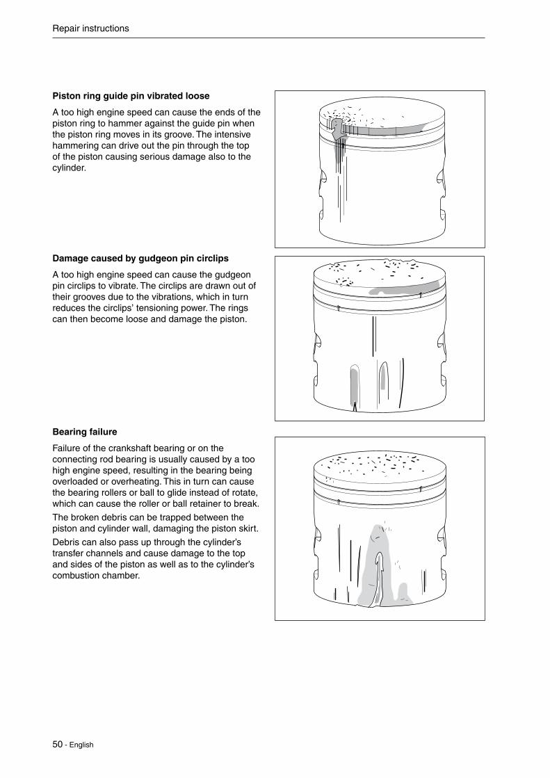
Piston ring guide pin vibrated loose
A too high engine speed can cause the ends of the piston ring to hammer against the guide pin when the piston ring moves in its groove. The intensive hammering can drive out the pin through the top of the piston causing serious damage also to the cylinder.
Damage caused by gudgeon pin circlips
A too high engine speed can cause the gudgeon pin circlips to vibrate. The circlips are drawn out of their grooves due to the vibrations, which in turn reduces the circlips’ tensioning power. The rings can then become loose and damage the piston.
Bearing failure
Failure of the crankshaft bearing or on the connecting rod bearing is usually caused by a too high engine speed, resulting in the bearing being overloaded or overheating. This in turn can cause the bearing rollers or ball to glide instead of rotate, which can cause the roller or ball retainer to break.
The broken debris can be trapped between the piston and cylinder wall, damaging the piston skirt.
Debris can also pass up through the cylinder’s transfer channels and cause damage to the top and sides of the piston as well as to the cylinder’s combustion chamber.

English - 51
Repair instructions
Foreign objects
Everything other than clean air and pure fuel that enters the engine’s inlet port causes some type of abnormal wear or damage to the cylinder and piston.
This type of increased wear shows on the piston’s inlet side starting at the lower edge of the piston skirt.
The damage is caused by badly filtered air that passes through the carburetor and into the engine
Inlet side.Particles of dust and dirt from carbon-like deposits on the top of the piston and in the piston ring groove. The piston ring sits firmly in the groove. Piston material has been worn away.
The lower part of the piston skirt is thinner on the inlet side than on the exhaust side.
Cause: Action:
Faulty air filter. Small dust particles pass through the filter.
Replace to a correct and a new filter.
The filter is worn out due to too much clean-ing, whereby small holes have appeared in the material.
Check the filter care-fully for holes and damage after cleaning. Replace the filter if necessary.
Unsuitable filter mainte-nance, such as wrong method or wrong clean-ing agent. Flock mate-rial becomes loose and holes appear.
Clean more care-fully and use the right cleaning agent (such as tepid soapy water). Change the filter.
Air filter incorrectly fitted.
Fit the filter correctly.
Air filter damaged or missing
fit a new air filter
Larger, softer particles that penetrate into the engine cause damage to the piston skirt under the piston ring as the illustration shows.
Cause: Action:
Air filter incorrectly fitted.
Fit the air filter correctly.
Air filter damaged or missing.
Fit a new air filter.

52 - English
Repair instructions
Larger, harder particles that enter the engine cause serious damage to the underside of the piston skirt.
Cause: Action:
Air filter damaged or missing.
Fit a new air filter.
Parts from the carbure-tor or intake system have come loose and entered the engine.
Regular service and inspection.
Service tips
Defect: Action:
Broken cooling fins, damaged threads or sheared bolts by the exhaust port.
In severe cases – replace the cylinder.Repair the threads using Heli-Coil.
Seizure marks in the cylinder bore (especially by the exhaust port).
Polish the damaged area using a fine grade emery cloth so that the coating of aluminium disappears.With deep seizure score marks the piston and cylinder should be replaced.
Surface coating in the cylinder bore worn out (primarily at the top of the cylinder).
Replace the cylinder and piston.
The piston shows signs of seizure score marks Carefully polish the damaged area using a fine file of fine grade emery cloth. Before the piston is refitted the cylinder should be polished as above. With deep score marks the piston and cylinder should be replaced.
Piston ring burnt in its groove. Carefully loosen the piston rings and clean the groove well before refitting. Carbon deposits in the groove impair the important heat transfer between the piston and cylinder.
NOTE!Be careful with the lower edge of the piston ring groove. If this is damaged, or if carbon deposits remain, the compression pressure can leak through.
Check the wear on the piston ring by placing it in the lower part of the cylinder.
Bolts much too tight in the aluminium material. Position a suitable punch on the bolt head and give a few sharp knocks with a hammer. If the bolt still does not loosen, repeat the procedure.

English - 53
Repair instructions
Wear tolerances
Cylinder bore
When the surface coating is worn and aluminium appears
Piston ring gap
Max. 0,5 mm with the piston ring inserted in the lower part of the cylinder.
Piston ring groove
Max. 1,1 mm. Clean the groove before checking the measurement.
Piston ring play
Max. 0.1 mm. Clean the groove before checking the measurement.

54 - English
Repair instructions
7.22 Assembling the piston and cylinderClean the crankcase
Fit the piston on the connecting rod so that the arrow on the piston points towards the exhaust port. Lubricate the piston pin’s needle bearing with a few drops of engine oil.
NOTE!Place a rag in the crankcase opening to prevent the circlip from falling into the crankcase in case it should fly out. Check that the circlips are correctly fitted into the grooves by turning the clips with flat nosed pliers
Check the gasket halves is undamaged and is positioned correctly on the crankcase.
Lubricate the piston and the piston ring using a few drops of oil and carefully slide the cylinder over the piston.
NOTE!Do not turn the cylinder, as the piston rings can easily be broken.Tighten the 4 screws diagonally crosswise.
Assemble the remaining parts:
Intake system
Muffler
Carburetor
See specific instructions

English - 55
Repair instructions
The task of the crankshaft is to transform the reciprocating motion of the piston to rotation. This requires a stable design withstanding immense pressure and rotational and bending strain, as well as high rotational speed. In addition the connecting rod is exposed to large acceleration and retardation forces as it moves between the top and bottom dead centres. This puts special demands on the bearings that must withstand quick changes in load. Moreover, the bearing’s roller retainer must also cope with high temperatures and friction. It is therefore extremely important when servicing to check the roller retainer for cracks, wear and discolouration caused by overheating.
The crankshaft is journalled in the crankcase on heavy-duty ball bearings. In addition to the journalling point for the crankshaft, the crankcase acts as a scavenging pump for the fuel/air mixture when this is “sucked” from the carburetor and is forced into the cylinder’s combustion chamber. The crankcase must be perfectly sealed so as not to affect this pump function. There cannot be any leakage from the crankshaft, between the crankcase halves or between the crankcase and the cylinder.
Always replace the oil seal and gaskets when servicing the crankcase.
7.23 Dismantling crankshaft and crank-case
DismantlingDismantle all components so that only the crank-case and crankshaft remain.
See the respective sections for detailed information if necessary.
Remove the key from the crank shaft using a tool.
Remove the crankshaft out of the crankcase.
Remove the bearings and oil seal(press fit).
Remove the gasket between crankcase halfs an residue the base of the cylinder and crankcase.
Inspecting the crankshaftThe crankshaft cannot be reconditioned but must be replaced if it is worn or damaged.
Inspect the large end of the connecting rod. If seizure marks, discolouration on the sides or damaged needle holders are found the crankshaft must be replaced.

56 - English
Repair instructions
Inspect the small end of the connecting rod.
If seizure marks or discolouration are found in the bearing track the crankshaft must be replaced.
Check the crank bearing. The connecting rod shall not have any radial play (up and down).
It should, however, have axial play, in order to ensure good lubrication of the crank bearing among other things.
Check for wear and damage on the crankshaft’s bearing and on oil seal.
.
Bearing and oil seal should always be replaced by a new bearing and oil seal if it is damaged or worn out.

English - 57
Repair instructions
7.24 Assembling the crankshaft and crankcaseCheck the crankshaft as set out in the section ”Inspecting the crankshaft”.
Fit the new bearing in the crankcase using a press tool.
During press fit of the bearing don’t push the inner bearing to fit
Assemble the piston on the crankshaft.
Lubricate the big-end bearing with a few drops of engine oil and position the crankshaft in the crankcase. Use new gasket.
Insert the crankshaft into the crankcase bearing. Flywheel side might be tight. Use a press tool. don’t use a hammer. During this process hold the inner bearing from the back side by a solid piece.Assemble the crankcase by using a new gasket and cut off the ends of the gasket.
Assemble the oil seal into the crankcase using a press tool. And do not damage the oil seal lip during this process.
Assemble the cylinder on the piston. Use a new gasket.
Install the key onto the crankshaft. Upper surface of the key should be in parallel to the crankshaft axis

58 - English
Repair instructions
7.25 Replacing the clutch drum and drive shaft
The centrifugal clutch has the task of transferring the power from the engine to the cutting equip-ment’s drive shaft. As the name implies, it works according to a centrifugal principle.
This means the clutch’s friction shoes are thrown outwards towards the clutch drum at a certain engine speed. When the friction against the drum is sufficiently great it drives the drive shaft at the same speed as the engine.
Some slipping occurs between the clutch and the clutch drum when accelerating as well as in the reversed situation when the cutting equipment jams. Thereby preventing abnormal load changes on the crankshaft.
The engagement speed has been carefully tested so that the engine can idle without the cutting equipment’s drive shaft rotating.
7.26 Dismantling and assembling the clutch drum and drive shaft
See removal instruction in chapter 7.5.
.

English - 59
Repair instructions
Remove the screw (A) and screw (B) that hol-ding the clamp connection for the shaft.
Remove the two screws holding the clutch hou-sing cover.
Pull apart the shaft from the clutch housing.
A
B

60 - English
Repair instructions
Remove the upper and lower clamp.
Remove the anti vibrations element
Note!replace the antivibration element if it is damaged orcracked.
Remove the small circlip from around the shaft on the clutch drum using suitable circlip pliers. 515 41 95-01
Dismantle the clutch drum by using a specila tool, 581 44 10-01.
Dismantle the ring using a circlip pliers.
Dismatle the bearing using an appropriate punch and hammer.
Assemble in the reverse order as set out for dis-mantling. Use a press tool for installing bearing and clutch drum.
Note!Always use new bearings, if the clutch drum is removed.

English - 61
Repair instructions
7.27 Dismantle lever and hook shaftLoosen screw from handle. Pull the handle back-wards and loosen the hook shaft by hand from its fix point.
Remove the hook shaft from its fixing points on the gear.
7.28 Separate gear box from shaftLoosen 2 screws holding the gear and cutting deck on shaft.
Remove gear and cutting deck from shaft.

62 - English
Repair instructions
7.29 Separate gear and cutting deck
Loosen and remove nut including 2 spring washers and the washer.
If needed usea screwdriver to hold the locking screw, see figure.
7.30 Dismantling spiral bevel gear
Remove the outer retainning ring (A).
Heat up the houseing. Approximately: 110° C
Knock the bevel gear gently against a wooden block. The spiral bevel gear (B) and the two bearings (C) will come loose.
Visually inspect cogs, bearings and if worn or damaged replace it.
A
C
B
D

English - 63
Repair instructions
7.31 Dismantling cutting deck houseLoosen the screw to the cutter. Use a screw driver to hold the knifes in place.
Loosen therest of the 6 screws.
Separate the upper and lower part of the gear housing. Use a screwdriver in the gap between the housing parts.

64 - English
Repair instructions
Remove the guide plate and the sealing holding the cutter.
Remove the washer, spring washer and the pres-sure washer.Lift off the upper rod, spur gear and lower rod.
7.32 Dismantling cutting deck
Loosen and rwemove the nuts holding the cutting deck.
Loosen and remove the three screws, bolts and washers holding the blades and bar together.
If the blades have burs, sharpen the blades using a suitable tool.

English - 65
Repair instructions
7.33 Assembly the cutting deckAssembly the cutting blades and bars together. Use a new screw and tighten it then loosen screw so there is a gap of 0,10±0,05 mm. Use a gauges for a correct tolerence. Then tighten the nut.
7.34 Assembly cutting deck housePress the bearing into place using a suitable tool. Make sure to press on the outer ring on the bearing.Put the pressure washer, the spring washer(X) and the washer(Y) in the lower housing part.
Place the lower rod, spur gear and upper rod in the upper housing.
Important!Always use Shell Gadus grease on every moving part.
Assembly the cutter deck in the gear house. Make sure that the both lower and upper rod is placed correct in the gear and connected to the blades.
0.10 0.05 mm+-
X
Y

66 - English
Repair instructions
Assembly the gear house. Tighten the 6 screws.Tighten the screw to the cutter deck.
7.35 Assembly spiral bevel gearPlace the spiral bevel gear on the threaded shaft.Press parts together.
Place the washer and the spring washers on the threaded shaft. Make sure that the spring washers are correct fitted, see figure.Tighten the nut with
7.36 Angle adjustment of the cutting deckMake sure there always is a space between clamp and the nut/screw end. If not us a file to make the gap between clamp and the nut.

English - 67
Repair instructions
Tighten the nut on the gear to make sure to fix the angle adjustment of the clamp connection of the locking adjustment of the gear.
Tighten the nut until it get contact with the two spring washers. Torque: 5 Nm.
Make sure there is a gap left when the clamp is locked (tightened), if not gearhousing parts are worn out and need to be replaced.

68 - English
Repair instructions
7.37 Assembly lever and hook shaft
Tighten the hook shaft to the fix point on the gear.
Place the hook shaft in it’s fixing point on the handle
7.38 Apply GreaseApply Grease through the nipple and through the grease plug if needed. Use Shell Gadus greas.Approximately: 30 gr. grease in the nipple.Approximately: 10 gr grease in the plug.

English - 69
8 Troubleshooting
Contents8.1 Engine does not start ....................................................................................................678.2 Engine stops working during operation .........................................................................688.3 Engine is difficult to stop ................................................................................................688.4 Insufficient output or unstable rotation ..........................................................................698.5 Other engine problems ..................................................................................................708.6 Blades ............................................................................................................................71
Troubleshooting

70 - English
Troubleshooting
8.1 Engine does not startRemove the spark plug from the cylinder, and holding the cylinder, pull the recoil starter and check whether any sparks appear between the spark plug electrodes.
Symptom/Category Cause Action
There are no sparks at the spark plug
Spark plug
1. The spark plug electrodes are wet Dry them
2. Carbon has built up on the spark plug electrodes
Remove the carbon or replace with a new one.
3. Insulation is poor due to cracks, etc. on the spark plug insulator
Replace with a new one.
4. The gap between the spark plug electro-des is excessively small or large
BPMR8Y: Adjust to 0.65 mm
Magneto
1. Poor coil insulation Replace
2. The cable trunking has been damaged or the cable is broken
Repair or replace
3. Poor air gap between the rotor and coil Adjust to 0.3 mm
4. Damage to the plug and gap spring Replace
Switch
1. The switch is OFF Set the switch to “RUN”
2. The switch is faulty Replace
3. The primary wire is earthed Repair or replace
There are sparks at the spark plug
Compression is good and fuel flows
1. Excessive fuel intake Discharge the excess gas
2. Fuel is too thick Repair or replace the carbu-retor
3. Overflow Adjust or replace the carbure-tor
4. The air cleaner is soiled Clean in a gasoline mixture and dry thoroughly
5. Poor quality fuel is being used Replace with good quality fuel
Fuel flows, but compression is poor
1. The spark plug is loose Tighten
2. Wear or damage to the cylinder, piston, piston
Replace
3. Gas is leaking from around the cylinder and crankcase
Replace gasket with new one and re-assemble
No fuel flows
1. Poor carburetor adjustment Adjust
2. Blockage inside the carburetor Clean
3. Blockage in the fuel filter Clean or replace the fuel filter
4. Fuel hose damage or blockage Adjust
8 Troubleshooting
English - 71
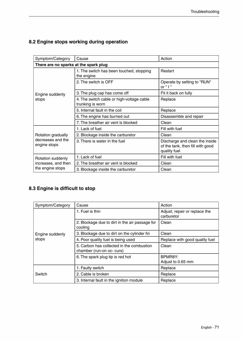
8.2 Engine stops working during operation
Symptom/Category Cause Action
There are no sparks at the spark plug
Engine suddenly stops
1. The switch has been touched, stopping the engine
Restart
2. The switch is OFF Operate by setting to "RUN" or " I "
3. The plug cap has come off Fit it back on fully
4. The switch cable or high-voltage cable trunking is worn
Replace
5. Internal fault in the coil Replace
6. The engine has burned out Disassemble and repair
7. The breather air vent is blocked Clean
Rotation gradually decreases and the engine stops
1. Lack of fuel Fill with fuel
2. Blockage inside the carburetor Clean
3. There is water in the fuel Discharge and clean the inside of the tank, then fill with good quality fuel
Rotation suddenly increases, and then the engine stops
1. Lack of fuel Fill with fuel
2. The breather air vent is blocked Clean
3. Blockage inside the carburetor Clean
8.3 Engine is difficult to stop
Symptom/Category Cause Action
Engine suddenly stops
1. Fuel is thin Adjust, repair or replace the carburetor
2. Blockage due to dirt in the air passage for cooling
Clean
3. Blockage due to dirt on the cylinder fin Clean
4. Poor quality fuel is being used Replace with good quality fuel
5. Carbon has collected in the combustion chamber (run-on oc- curs)
Clean
6. The spark plug tip is red hot BPMR8Y: Adjust to 0.65 mm
Switch
1. Faulty switch Replace
2. Cable is broken Replace
3. Internal fault in the ignition module Replace
Troubleshooting

72 - English
8.4 Insufficient output or unstable rotation
Symptom/Category Cause Action
Compression is good and there is no flame out
1. Air has entered through the fuel pipe joint, etc.
Insert it securely
2. Air has entered the fuel pipe due to a crack or pin hole
Replace
3. Air has entered through the insulator pulse pipe insertion part, etc.
Insert it securely
4. Air has entered through the insulator and carburetor installa- tion part
Replace or tighten the gasket
5. Air has entered through the oil seal, etc. Replace
6. There is water in the fuel Discharge and clean the inside of the tank, then fill with good quality fuel
7. The piston appears to have been burned Remove the burn with a fine file, or replace
8. Carbon blockage in the muffler Clean
Excessive heat
1. Fuel is thin Repair or replace the carbu-retor
2. Blockage due to dirt in the air passage for cooling
Clean
3. Blockage due to dirt on the cylinder fin, etc.
Clean
4. Poor quality fuel is being used Replace with good quality fuel
5. Carbon has built up in the combustion chamber
Clean
6. The spark plug tip is red hot Clean carefully, and BPMR8Y: Adjust to 0.65 mm
Other1. The air cleaner is soiled Replace it with a new one
2. Excessive load Reduce the load
Troubleshooting

English - 73
8.5 Other Engine problems
Symptom/Category Cause Action
Even if the engine revolution is de-creased, the blade does not stop
1. The clutch spring is broken Replace the engine's clutch spring
2. The clutch is open due to rusting of the clutch bolts
De-rust the clutch bolts, apply grease and re-assemble
3. The shoe lining has peeled off Replace the shoe
Even if the engine revolution is increased, the blade does not rotate
1. The shaft is broken Replace
2. The flexible shaft is broken (back-supported type)
Replace
3. Drum bearing is stuck Replace
4. Gear damage inside the gear case Repair or replace
5. Gear damage inside the swivel gear case Repair or replace
6. Damage to the joint-C spring Replace
7. Abnormal wear to the drum and shaft's spline
Replace
Abnormal vibration
1. Blade eccentricity Fit the cutter holder (holder A) firmly and re-assemble
2. The chip saw's tip has worn down by a third or more
Replace the chip saw
3. Pipe is bent
4. The blade has a high peripheral balance Set the blade's teeth or replace
5. The shaft is bent Replace
6. The shaft damper is damaged or broken Replace
7. The outer pipe is bent Replace
8. Wear or movement of the bushing Replace the pipe
9. Eccentricity of the drum Replace the drum
10. Significant weight difference on the clutch shoe
Replace the clutch shoe
Troubleshooting

74 - English
8.6 Blades
Symptom/Category Cause Action
Blades are jammed. Blades cuts uneven.
1. Blades are dull, bent, chipped or other-wise damaged.
Sharpen the blades or replace the blades completely if heavily damaged.
2. Blades are loose at any pivot. Make sure all screws are correctly tightened.
3. Blades are not aligned. Make sure the blades are aligned.
Troubleshooting


2015W11
114
02 9
0-26


