
WORKSHOP 10 HEX VS TET SOLID ELEMENT MESH · PDF fileTitle: Microsoft PowerPoint - Ws10_ ...
64
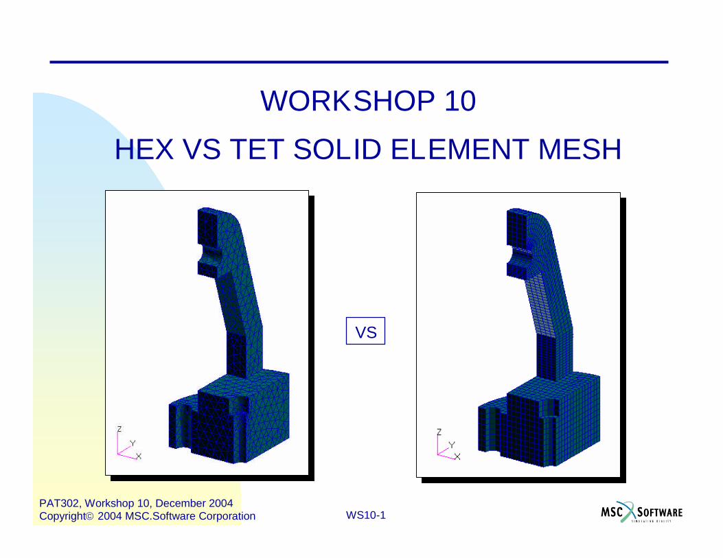
WS10-1 PAT302, Workshop 10, December 2004 Copyright2004 MSC.Software Corporation WORKSHOP 10 HEX VS TET SOLID ELEMENT MESH VS
Transcript of WORKSHOP 10 HEX VS TET SOLID ELEMENT MESH · PDF fileTitle: Microsoft PowerPoint - Ws10_ ...
WS10-1PAT302, Workshop 10, December 2004Copyright2004 MSC.Software Corporation
WORKSHOP 10
HEX VS TET SOLID ELEMENT MESH
VS

WS10-2PAT302, Workshop 10, December 2004Copyright2004 MSC.Software Corporation

WS10-3PAT302, Workshop 10, December 2004Copyright2004 MSC.Software Corporation
Problem Description This workshop is for creating a tetrahedral and hexahedral element
mesh for a geometric solid. The tetrahedral mesh can be createdquickly and easily using the standard tet mesher TetMesh.
Creating the hexahedral mesh involves doing much more work. Thetask involves dividing the geometry into two parts. Groups are usedto segregate the parts. The hex mesh for the first part is created bycreating a combination of IsoMesh and Paver meshes, thensweeping them to create the hex solid elements.
The hex elements for the second part are created by using themesher IsoMesh. First, the blue colored parametric solids must becreated. The techniques used are simple. There is one difficultyassociated with creating two solids; they are very skewed, and thisaffects the meshing.
The hex element meshes are combined, and the continuity of themis investigated.
WS10-4PAT302, Workshop 10, December 2004Copyright2004 MSC.Software Corporation
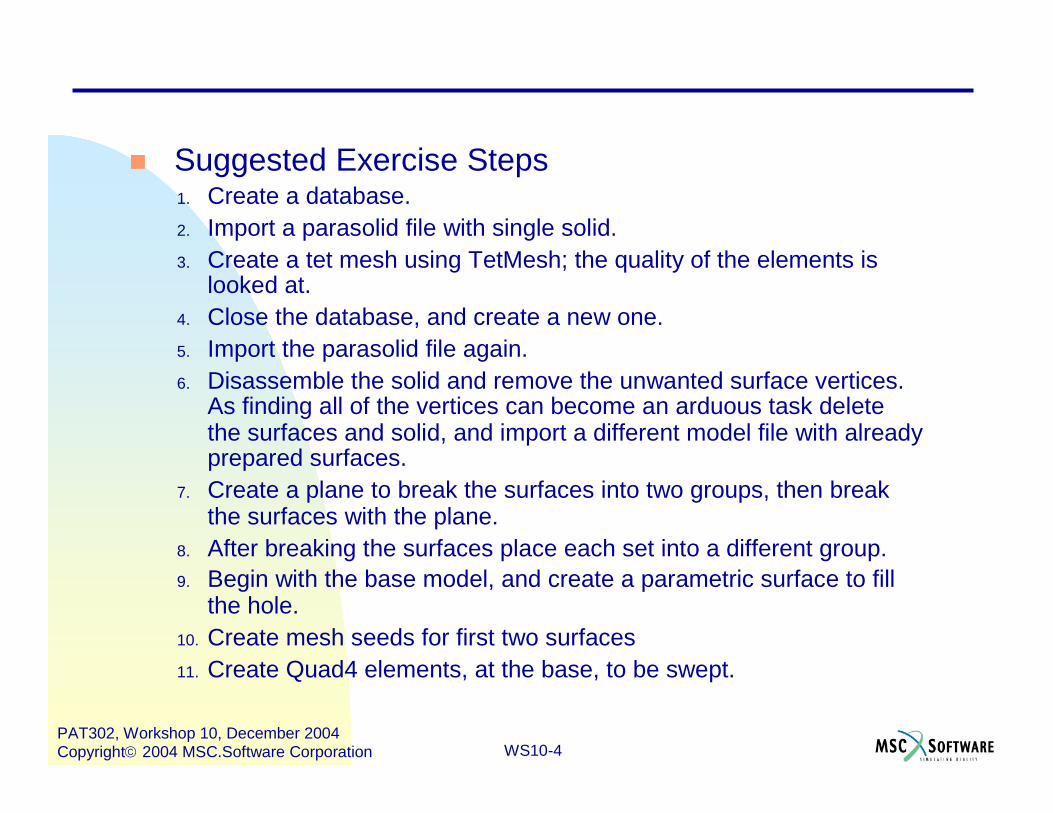
Suggested Exercise Steps1. Create a database.2. Import a parasolid file with single solid.3. Create a tet mesh using TetMesh; the quality of the elements is
looked at.4. Close the database, and create a new one.5. Import the parasolid file again.6. Disassemble the solid and remove the unwanted surface vertices.
As finding all of the vertices can become an arduous task deletethe surfaces and solid, and import a different model file with alreadyprepared surfaces.
7. Create a plane to break the surfaces into two groups, then breakthe surfaces with the plane.
8. After breaking the surfaces place each set into a different group.9. Begin with the base model, and create a parametric surface to fill
the hole.10. Create mesh seeds for first two surfaces11. Create Quad4 elements, at the base, to be swept.

WS10-5PAT302, Workshop 10, December 2004Copyright2004 MSC.Software Corporation
Suggested Exercise Steps (continued)12. Create Hex8 Elements by Sweeping Quad4s at the base.
13. Create Seeds, IsoMesh, Then Sweep to Hex8s.
14. Create Mesh Seeds in Preparation for Paver Mesh.
15. Create Paver Mesh Using Seeds.
16. Complete Sweeping Quads to Create Hexs.
17. Delete Quad Elements and Connect Hex Elements.
18. Post Group “Top” With Surfaces for creating parametric Solids.
19. Create Parametric Solids From parametric Surfaces.
20. Create Curves to be Used for Creating Surfaces.
21. Create Parametric Surfaces From Curves.
22. Create Parametric Solids From Surfaces.
23. Display Both Parts of the Model.
24. Create Mesh Seeds to force Congruent Hex Meshes.

WS10-6PAT302, Workshop 10, December 2004Copyright2004 MSC.Software Corporation
Suggested Exercise Steps (continued)25. Create Hex Meshes for the “Top” Part of Model.
26. Connect Hexs in “Top” Part of Model.
27. Determine Quality of Hex Mesh.

WS10-7PAT302, Workshop 10, December 2004Copyright2004 MSC.Software Corporation
Create a new database.a. File/New.b. Enter tet as the file name.c. Click OK.d. Choose Based on Model for
Tolerance.e. Select MSC.Nastran as the
Analysis Code.f. Select Structural as the
Analysis Type.g. Click OK.
a
b
e
f
d
cg
Step 1. Create a Database

WS10-8PAT302, Workshop 10, December 2004Copyright2004 MSC.Software Corporation
Step 2. Import Parasolid File
Import the parasolid.xmt file.a. File / Import.b. Change the Source to
Parasolid.xmt.c. Select part.xmt.d. Click on Apply.e. Click on OK when the import
summary appears.
a c
d
e

WS10-9PAT302, Workshop 10, December 2004Copyright2004 MSC.Software Corporation
Step 3. Create a TetMesh Mesh
TetMesh the solid.a. Elements: Create/Mesh/Solid.b. Set Elem Shape to Tet.c. Set Mesher to TetMesh.d. Under Input List select Solid 1.e. Under Global Edge Length
enter 5.0.f. Click Apply.g. Change to Iso 3 view and
Smooth shaded.
a
c
d

WS10-10PAT302, Workshop 10, December 2004Copyright2004 MSC.Software Corporation
Check the quality of theelements
a. Elements: Verify/Tet/All.
b. Click on Apply.
Step 3. Create a TetMesh Mesh (Cont.)
2050Min = 0.200359970Jacobian Zero
3623Max = 9.24094390Jacobian Ratio
5181Max = 0.331530215Tangent Offset
3033Max = 0.26516628131Normal Offset
6420Min = 0.0637227520Collapse
6420Max = 80.1382223381Face Skew
4599Max = 77.1549223020Edge Angle
6420Max = 4.01462940Aspect
At ElementWorst CaseNumber FailedTest
This method wasstraightforwardand quite simple.It can beobserved that6420 Tet10Elements werecreated.
a
b
WS10-11PAT302, Workshop 10, December 2004Copyright2004 MSC.Software Corporation
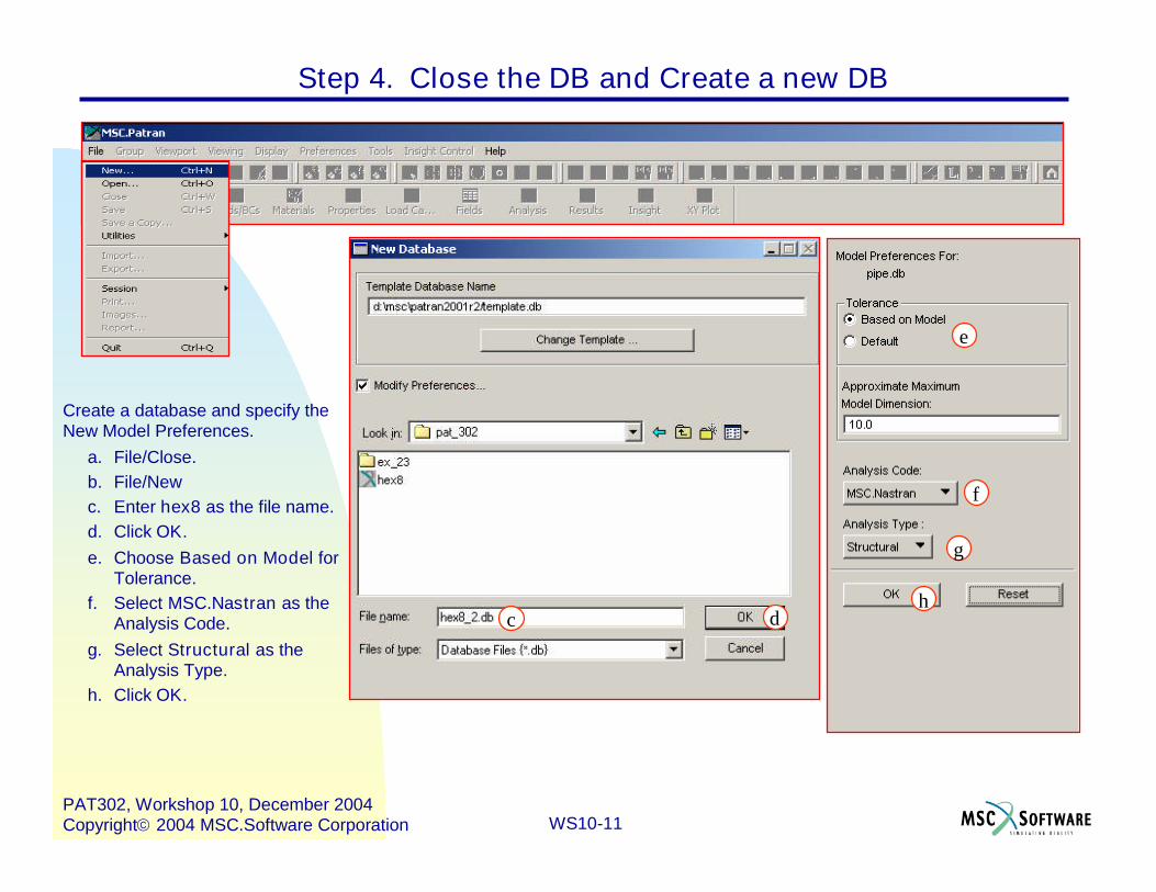
Step 4. Close the DB and Create a new DB
Create a database and specify theNew Model Preferences.
a. File/Close.b. File/Newc. Enter hex8 as the file name.d. Click OK.e. Choose Based on Model for
Tolerance.f. Select MSC.Nastran as the
Analysis Code.g. Select Structural as the
Analysis Type.h. Click OK.
c d
e
g
h
f

WS10-12PAT302, Workshop 10, December 2004Copyright2004 MSC.Software Corporation
Step 5. Import the Parasolid File Again
Import the parasolid filepart.xmt.
a. File/Import.b. Select part.xmt.c. Click on Apply.d. Click on OK when the import
summary appears.
ab
c
d

WS10-13PAT302, Workshop 10, December 2004Copyright2004 MSC.Software Corporation
Step 6. Disassemble the Parasolid Solid
Prepare the solid so that a hexmesh can be created. Start bydisassembling the parasolid.
a. Geometry: Edit/Solid/Disassemble.
b. For Solid List select Solid 1.c. Click on Apply.d. Select Yes when asked to
delete the original solids.e. Click on the Label Control
icon and turn on the surfacelabels.
a
b
c

WS10-14PAT302, Workshop 10, December 2004Copyright2004 MSC.Software Corporation
Step 6. Disassemble the Parasolid Solid (Cont.)
Note that the surfaces are trimmed(indicated by the magenta lines).Where possible create parametricsurfaces (green) from trimmedsurfaces. To do this do:
a. Geometry:Create/Surface/Curve
b. Geometry: Edit/Surface/Remove Vertex
It may be difficult to remove all thevertices that should be, because ofthe difficulty in identifying them.Therefore, delete the model andimport an IGES file with all thesurfaces already edited.
c. Delete the model.d. File/Import…e. Change the Source to
IGES.f. Select the file surfaces.igs.g. Click on Apply.
a
b
In order to simplify theexercise the newly importedsurfaces are already edited.
Surfaces from surfaces.igs

WS10-15PAT302, Workshop 10, December 2004Copyright2004 MSC.Software Corporation
Step 7. Create a Plane to Break the Surfaces
Break the surfaces to create tworegions for creating hex8 elements.A plane is used to break thesurfaces.
a. Geometry: Create/Plane/3 Points.
b. For Point 1 List selectPoint 17.
c. For Point 2 List selectPoint 18.
d. For Point 3 List selectPoint 5.
b
c
d
*
*
*

WS10-16PAT302, Workshop 10, December 2004Copyright2004 MSC.Software Corporation
Break the surfaces with the newlycreated plane.
a. Geometry: Edit/Surface/Break.
b. Option: Plane.c. Surface List: select all
surfaces.d. Break Plane List: select
Plane 1.e. Select Yes for All when
asked to delete originalsurfaces.
Step 7. Create a Plane to Break the Surfaces (Cont.)
a
b
c
d

WS10-17PAT302, Workshop 10, December 2004Copyright2004 MSC.Software Corporation
Step 8. Place each set of Surfaces Into Different Groups
Create two groups for different regions ofthe model. Start with the “base” region ofthe model.
a. Group/Create.b. For New Group Name enter base.c. Check Unpost All Other
Groups.d. Go to Preferences/Picking and
change the Rectangle/PolygonPicking to Enclose entire entity
e. Change to the Right side viewf. For Entity Selection include the
surfaces shown in the figure.g. Click on Apply.
a
b
c
f
f

WS10-18PAT302, Workshop 10, December 2004Copyright2004 MSC.Software Corporation
Shown here is the base regionof the model. The entities inthe two regions of the modelare to be placed in differentgroups to facilitate meshing.
Step 8. Place each set of Surfaces Into Different Groups (Cont.)

WS10-19PAT302, Workshop 10, December 2004Copyright2004 MSC.Software Corporation
Post the group default_group and create agroup for the remaining region of themodel.
a. Post the group default_group.b. Group/Create.c. For the New Group Name enter
top.d. Check Unpost All Other Groups.e. Go to Preferences/Picking and
change the Rectangle/PolygonPicking to Enclose any portion ofentity
f. Switch to the Right side view andunder Entity Selection include thesurfaces shown in the figure.
g. Click on Apply.
Step 8. Place each set of Surfaces Into Different Groups (Cont.)
b
c
d
f
f

WS10-20PAT302, Workshop 10, December 2004Copyright2004 MSC.Software Corporation
Step 8. Place each set of Surfaces Into Different Groups (Cont.)

WS10-21PAT302, Workshop 10, December 2004Copyright2004 MSC.Software Corporation
Step 9. Create a Parametric Surface to Fill Hole
Enclose the base region withsurfaces by creating a parametricsurface where the plane is.
a. Post the group base.b. Go to the Iso 1 view.c. Geometry: Create/
Surface/Curve.d. Set the Option to 2
Curve.e. Under Starting Curve List
select Surface 22.3.f. Under Ending Curve List
select Surface 13.2.
c
d
e
f

WS10-22PAT302, Workshop 10, December 2004Copyright2004 MSC.Software Corporation
Step 10. Create Mesh Seeds for First two Surfaces
Create a mesh seed for the base sothat a quad mesh can be applied(the quad mesh will later be swept tocreate a hex8 mesh).
a. Elements: Create/Mesh Seed/Uniform.
b. Enter 9 for the Number.c. For Curve List select Surface
13.1.d. Set the Number to 3 and
select Surface 26.1 for theCurve List.
e. Set the Number to 4 andselect Surface 26.2 andSurface 8.4 for the CurveList.
a
b
c
WS10-23PAT302, Workshop 10, December 2004Copyright2004 MSC.Software Corporation
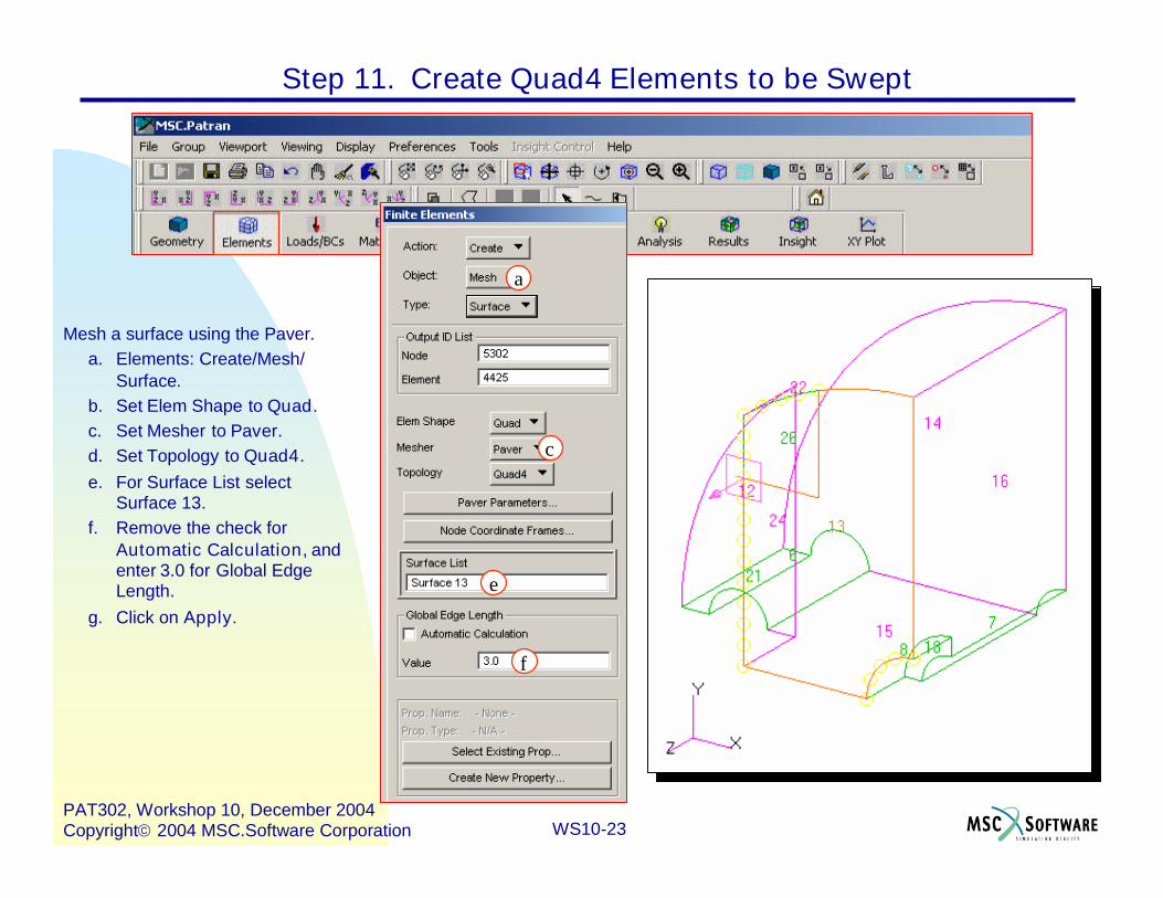
Mesh a surface using the Paver.a. Elements: Create/Mesh/
Surface.b. Set Elem Shape to Quad.c. Set Mesher to Paver.d. Set Topology to Quad4.e. For Surface List select
Surface 13.f. Remove the check for
Automatic Calculation, andenter 3.0 for Global EdgeLength.
g. Click on Apply.
Step 11. Create Quad4 Elements to be Swept
a
c
f
e

WS10-24PAT302, Workshop 10, December 2004Copyright2004 MSC.Software Corporation
Mesh another surface using IsoMesh.a. Elements: Create/Mesh/
Surface.b. Set Elem Shape to Quad.c. Set Mesher to IsoMesh.d. Set Topology to Quad4.e. For Surface List select
Surface 26.f. Remove the check for
Automatic Calculation, andenter 3.0 for the Global EdgeLength.
g. Click on Apply.
Step 11. Create Quad4 Elements to be Swept (Cont.)

WS10-25PAT302, Workshop 10, December 2004Copyright2004 MSC.Software Corporation
Here are the surface meshes forpart of the base. The meshes willbe swept to create a hex mesh forthe base part of the model.
Step 11. Create Quad4 Elements to be Swept (Cont.)

WS10-26PAT302, Workshop 10, December 2004Copyright2004 MSC.Software Corporation
Step 12. Create Hex8 Elements by Sweeping Quad4s
Sweep the surface meshes tothe first section.
a. Elements : Sweep/Element/Extrude.
b. Under Mesh Control,enter 3 for Number.
c. Click on OK.d. Select on Direction
Vector and select theTip and base pointsicon. Then, select Tipand Base points asshown in the figure.
e. For selecting the BaseEntity List entities usethe Meshed entity icon,then the MeshedSurface icon.
f. Select Surfaces 13 and26 for the Base EntityList.
g. Click on Apply.
a
b
d
f d
g
e

WS10-27PAT302, Workshop 10, December 2004Copyright2004 MSC.Software Corporation
Step 12. Create Hex8 Elements by Sweeping Quad4s (Cont.)

WS10-28PAT302, Workshop 10, December 2004Copyright2004 MSC.Software Corporation
Sweep the free faces of the hexelements to the next section.
a. Elements : Sweep/Element/Extrude.
b. Enter 1 for Number underMesh Control, and clickOK.
c. Click on Direction Vectorand select on Tip and basepoints icon. Then, selectTip and Base points asshown in the figure.
d. Go to Preferences/Pickingand select Enclose entireentity.
e. Change to Right side viewand click on the Element’sface icon.
f. Under Base Entity Listselect the element faces asshown in the figure.
g. Click Apply.
f
c
c
f
Step 12. Create Hex8 Elements by Sweeping Quad4s (Cont.)

WS10-29PAT302, Workshop 10, December 2004Copyright2004 MSC.Software Corporation
The elements have been swept twiceto create the model illustrated below.Note that the nodes line up as theyshould.
Step 12. Create Hex8 Elements by Sweeping Quad4s (Cont.)

WS10-30PAT302, Workshop 10, December 2004Copyright2004 MSC.Software Corporation
Step 13. Create Seeds, IsoMesh, Then Sweep to Hex8s
IsoMesh the surface in a corner(Surface 18) to create elements thatwill be swept. First, because of thecurvature (90 degree bend) it isnecessary to create mesh seeds.
a. Switch to the Iso 1 view andzoom into Surface 18.
b. Elements: Create/Mesh Seed/Uniform.
c. Enter 4 for the Number.d. For Curve List select Surface
7.2.
a
d

WS10-31PAT302, Workshop 10, December 2004Copyright2004 MSC.Software Corporation
Mesh another surface using IsoMesh,then sweep the elements created.
a. Elements: Create/Mesh/Surface.
b. Set Elem Shape to Quad.c. Set Mesher to IsoMesh.d. Set Topology to Quad4.e. For Surface List select
Surface 18.f. Remove the check for
Automatic Calculation, andenter 3.0 for the Global EdgeLength.
g. Click on Apply.
h. Now, sweep the mesh justcreatedElements: Sweep/Element/Extrude.
i. Enter 1 for Number underMesh Control, and click OK.
j. Click on Direction Vector andselect on Tip and basepoints icon. Then, select Tipand Base points as shown inthe figure.
e
e
jj
Step 13. Create Seeds, IsoMesh, Then Sweep to Hex8s (Cont.)

WS10-32PAT302, Workshop 10, December 2004Copyright2004 MSC.Software Corporation
Finish sweeping the elements.a. Elements : Sweep/
Element/Extrude.b. For selecting the Base
Entity List entities usethe Meshed entity icon,then the MeshedSurface icon.
c. Select Surface 18 forthe Base Entity List.
d. Click on Apply.
Step 13. Create Seeds, IsoMesh, Then Sweep to Hex8s (Cont.)

WS10-33PAT302, Workshop 10, December 2004Copyright2004 MSC.Software Corporation
Step 14. Create Mesh Seeds in Preparation for Paver Mesh
Paver mesh Surface 12 so that themesh can be swept to create hexelements for part of the base. Themesh to be created must match thatalready created by sweeping. Meshseed are to be created using existingnodes.
a. Elements: Create/Mesh Seed/Tabular.
b. For the Coordinate Type selectNode and Point.
c. Under the Nodes or Points Listselect the Nodes as shown inthe figure.
d. Select Surface 12.2 underCurve List.
e. Click on Apply.
a
b
d
e
cc
d

WS10-34PAT302, Workshop 10, December 2004Copyright2004 MSC.Software Corporation
Step 14. Create Mesh Seeds in Preparation for Paver Mesh (Cont.)

WS10-35PAT302, Workshop 10, December 2004Copyright2004 MSC.Software Corporation
Step 15. Create Paver Mesh Using Seeds
Mesh the surface where one of itsedges was just seeded.
a. Elements : Create/Mesh/Surface.
b. For Elem Shape selectQuad.
c. For Mesher select Paver.d. For Topology select Quad4.e. Select Surface 12 for
Surface List.f. Use 3.0 for Global Edge
Lengthg. Click on Apply.

WS10-36PAT302, Workshop 10, December 2004Copyright2004 MSC.Software Corporation
Step 15. Create Paver Mesh Using Seeds (Cont.)

WS10-37PAT302, Workshop 10, December 2004Copyright2004 MSC.Software Corporation
Step 16. Complete Sweeping Quads to Create Hexs
Complete sweeping element faces and2D quad elements to the side of themodel.
a. Elements: Sweep/Element/Extrude.
b. Go to Mesh Control and enter 8for Number, and click OK.
c. Click on Direction Vector andselect on Tip and Base pointsicon. Then, select the Tip andBase points as shown in thefigure.
d. Under Base Entity List click onthe Element’s Face icon.
e. Switch the view to Top view,and select the elements asindicated.
f. Click on Apply.
c
c
de

WS10-38PAT302, Workshop 10, December 2004Copyright2004 MSC.Software Corporation
Step 16. Complete Sweeping Quads to Create Hexs (Cont.)

WS10-39PAT302, Workshop 10, December 2004Copyright2004 MSC.Software Corporation
Complete sweeping 2D quad elementsto the side of the model.
a. Elements: Sweep/Element/Extrude.
b. Go to Mesh Control and enter 8for Number, and click OK.
c. Click on Direction Vector andselect on Tip and Base pointsicon. Then, select the Tip andBase points as shown in thefigure.
d. Under Base Entity List click onthe 2D element icon.
e. Switch the view to Top view,and select the elements asindicated.
f. Click on Apply.
e
d
c
c
Step 16. Complete Sweeping Quads to Create Hexs (Cont.)

WS10-40PAT302, Workshop 10, December 2004Copyright2004 MSC.Software Corporation
Step 16. Complete Sweeping Quads to Create Hexs (Cont.)

WS10-41PAT302, Workshop 10, December 2004Copyright2004 MSC.Software Corporation
Delete 2D elements, then equivalence.a. Elements: Delete/Element.b. Elements:
Equivalence/All/Tolerance Cube.
Delete 2D Elements Equivalence
Step 17. Delete Quad Elements and Connect Hex Elements

WS10-42PAT302, Workshop 10, December 2004Copyright2004 MSC.Software Corporation
Completed hex mesh for the base partof the model. Now, verify that all thehex elements are connected.
a. Elements:Verify/Element/BoundariesFree Edges
Step 17. Delete Quad Elements and Connect Hex Elements (Cont.)

WS10-43PAT302, Workshop 10, December 2004Copyright2004 MSC.Software Corporation
Step 18. Post Group “Top” With Surfaces for Blue Solids
Create parametric solids(blue) forthe remainder of the model, andIsoMesh them with hex elements.Post the group top.
a. Group/Post.b. Under Select Groups to Post
select top.c. Click on Apply, then
Cancel.d. Go to the Iso 1 view .
a
b

WS10-44PAT302, Workshop 10, December 2004Copyright2004 MSC.Software Corporation
Step 19. Create Parametric Solids From Surfaces
Create the first parametric solidusing two surfaces
a. Geometry: Create/Solid/Surface.
b. Set the Option to 2 Surface.c. Select Surface 23 for the
Starting Surface List.d. Select Surface 3 for the
Ending Surface List.
a
b
c
d
WS10-45PAT302, Workshop 10, December 2004Copyright2004 MSC.Software Corporation
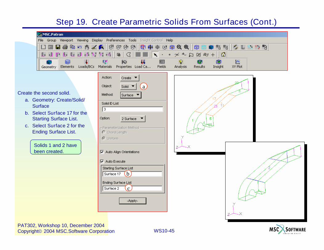
Create the second solid.a. Geometry: Create/Solid/
Surfaceb. Select Surface 17 for the
Starting Surface List.c. Select Surface 2 for the
Ending Surface List.
Solids 1 and 2 havebeen created.
a
b
c
Step 19. Create Parametric Solids From Surfaces (Cont.)

WS10-46PAT302, Workshop 10, December 2004Copyright2004 MSC.Software Corporation
To create the remaining solids it willbe necessary to create somecurves, surfaces from the curves,then solids from the surfaces.
a. Geometry: Edit/Curve/Break.
b. Rotate the view to get thefollowing view of the model.
c. Set the Option toParametric.
d. Enter 0.7 for the BreakPoint.
e. Select Surface 4.2 and 4.4for the Curve List.
f. Increase the point size.
Step 20. Create Curves to be Used for Creating Surfaces
a
c
d
e e
e

WS10-47PAT302, Workshop 10, December 2004Copyright2004 MSC.Software Corporation
Break curves again to obtain allneeded curves.
a. Geometry: Edit/Curve/Break.b. Set the Option to Parametric.c. Set the Break Point to 0.5.d. Under Curve List select
Curve 1 and 3.e. Click on Apply.
Step 20. Create Curves to be Used for Creating Surfaces (Cont.)

WS10-48PAT302, Workshop 10, December 2004Copyright2004 MSC.Software Corporation
Step 21. Create Parametric Surfaces From Curves
Create surfaces using the curves justcreated and previously existing surfaceor solid edges.
a. Geometry: Create/Surface/Curve.
b. Option: 2 Curve.c. Select curves or edges for
Starting Curve List and EndingCurve List.
Curve 5Surface 5.4
Curve 8Solid 2.2.1
Curve 7Surface 5.2
EndingCurve List
StartingCurve List
Curve 6Solid 2.2.3
Curve 4Surface 1.2
Curve 2Surface 1.4

WS10-49PAT302, Workshop 10, December 2004Copyright2004 MSC.Software Corporation
Step 22. Create Parametric Solids From Surfaces
Create the parametric solids.a. Geometry: Create/Solid/
Surface.b. Set Option to 2 Surface.c. Select the surfaces, as
specified in the table, forStarting Surface List andEnding Surface List.
EndingSurface List
StartingSurface List
Surface 32Surface 31
Surface 30Surface 29
Surface 28Surface 27

WS10-50PAT302, Workshop 10, December 2004Copyright2004 MSC.Software Corporation
Step 22. Create Parametric Solids From Surfaces (Cont.)

WS10-51PAT302, Workshop 10, December 2004Copyright2004 MSC.Software Corporation
Post the group for the base and topportion of the model.
Step 23. Both Parts of the Model

WS10-52PAT302, Workshop 10, December 2004Copyright2004 MSC.Software Corporation
IsoMesh the five new parametricsolids. It is desired to have the hexmesh in Solid 1 and the base part ofthe model congruent. The fact thatthere is a 2D IsoMesh associated toSurface 26 should control the IsoMeshof Solid 1. However, Solid 1 is verydistorted. This will prevent the meshcreated in it from being closelycongruent to the mesh on Surface 26.So, mesh seeds are to be created onthe other two edges of Surface 26.
a. Elements: Create/Mesh Seed/Tabular.
b. Select the Node and Pointtoggle.
c. Select the nodes shown in thefigure. It may be easier toselect the nodes by erasing thefive solids that were justcreated. See the next page.
Step 24. Create Mesh Seeds for Congruent Hex Meshes

WS10-53PAT302, Workshop 10, December 2004Copyright2004 MSC.Software Corporation
Continuation of creating mesh seedusing tabular approach.
a. Select the Node and Pointtoggle.
b. Select the nodes shown in thefigure.
c. Select the two edges forSurface 26 indicated by the redlines. Surface 13 adjacent toSurface 26 so its edges will bepicked.
d. Before clicking Apply thetolerance needs to be changedbecause of the distorted shapeof Solid 1. It is recommended touse 0.05 instead of the default0.005.
e. Apply.
Step 24. Create Mesh Seeds for Congruent Hex Meshes (Cont.)

WS10-54PAT302, Workshop 10, December 2004Copyright2004 MSC.Software Corporation
IsoMesh the five new solidsa. Elements: Create/Mesh/Solidb. Select Hex for Elem Shapec. Select IsoMesh for Mesherd. Under Solid List select Solid
1:5e. Specify 3.0 for Global Edge
Lengthf. Apply
Step 25. Create Hex Meshes for “Top” Part of Model

WS10-55PAT302, Workshop 10, December 2004Copyright2004 MSC.Software Corporation
IsoMesh issues an error message. MeshingSolid 1 with the constraint from the mesh onSurface 26, and the solid’s poor shape hascaused the failure. This is seen on the nextpages.
Solid 1.1.3
Solid 1.2.3
Step 25. Create Hex Meshes for “Top” Part of Model (Cont.)

WS10-56PAT302, Workshop 10, December 2004Copyright2004 MSC.Software Corporation
Copy the five solids, Solid 1:5, away fromthe model. Copy the mesh on Surface 26to the end of Solid 6, and associate it tothe end of the solid, Solid 6.3. IsoMesh allfive solids, Solid 6:10. The same errormessage is issued as before.
Delete the 2D mesh associated to the endof Solid 6, and IsoMesh all five solids. Ascan be seen all the solids were meshed.So, the mesh on Surface 26 is causingthe problem. However, it is worth while tosee that the shape of Solid 1 is related tothe problem. This is shown on the nextpage.
Step 25. Create Hex Meshes for “Top” Part of Model (Cont.)

WS10-57PAT302, Workshop 10, December 2004Copyright2004 MSC.Software Corporation
Reintroduce the 2D mesh on the end ofSolid 6. Then, extrude the same end ofSolid 6 to create a parametric solid, Solid11. IsoMesh Solid 11. The meshingsucceeded. So, given Solid 1 as it is, the2D mesh on Surface 26 is preventing themeshing from occurring. However, theshape of Solid 1, given the 2D mesh onSurface 26, is preventing the meshingfrom occurring.
Is this the complete story ? Proceed tofind out.
Step 25. Create Hex Meshes for “Top” Part of Model (Cont.)

WS10-58PAT302, Workshop 10, December 2004Copyright2004 MSC.Software Corporation
IsoMesh just Solid 1.a. Elements: Create/Mesh/Solidb. Select Hex for Elem Shapec. Select IsoMesh for Mesherd. Under Solid List select Solid 1e. Specify 3.0 for Global Edge
Lengthf. Apply
g. Under Solid List select Solid 2h. Specify 3.0 for Global Edge
Lengthi. Applyj. Under Solid List select Solid 3:5k. Specify 3.0 for Global Edge
Lengthl. Apply
So, Solid 1 meshed !Try meshing othersolids.
So, the problem wasrelated to Solid 1 and 2,and perhaps others.
Step 25. Create Hex Meshes for “Top” Part of Model (Cont.)

WS10-59PAT302, Workshop 10, December 2004Copyright2004 MSC.Software Corporation
Connect the hex elements.a. Elements: Equivalence/All/
Tolerance Cubeb. This model has some possible
problems, so set theequivalencing tolerance to 1.0.
c. Apply
It is detected that the tolerance is > thesmallest element edge. It is reset so it isslightly < the smallest element edge.
Step 26. Connect Hexs in “Top” Part of Model

WS10-60PAT302, Workshop 10, December 2004Copyright2004 MSC.Software Corporation
Determine if all the hex elements areconnected. First look at element freeedges. Then, look at element free faces.
a. Elements:Verify/Element/BoundariesFree Edges
b. Apply
c. Display just free faces usingDisplay/Finite Elements…Show Only Free Faces (InWireframe)
Step 26. Connect Hexs in “Top” Part of Model (Cont.)

WS10-61PAT302, Workshop 10, December 2004Copyright2004 MSC.Software Corporation
Look for any free faces at just certaingeometric interfaces. To do this create2D quad elements on element freefaces.
a. Elements: Create/Element/Editb. Shape: Quadc. Topology: Quad4d. Pattern: Elem Facee. Select Free face of element
picking iconf. Under Face select any desired
hex element free facesg. Erase everything except the 2D
quad elements just created.h. Rotate the model so that can see
if there are any hex free faceswhere there shouldn’t be.
Step 26. Connect Hexs in “Top” Part of Model (Cont.)

WS10-62PAT302, Workshop 10, December 2004Copyright2004 MSC.Software Corporation
Completed hex mesh for model. Now,look at the quality of the elements.
a. Elements: Verify/Hex/Face Warpb. Etc.
Step 27. Determine Quality of Hex Mesh

WS10-63PAT302, Workshop 10, December 2004Copyright2004 MSC.Software Corporation
Step 27. Determine Quality of Hex Mesh (Cont.)

WS10-64PAT302, Workshop 10, December 2004Copyright2004 MSC.Software Corporation


![TOPN Messages - Cisco · %TR-2-PANICINF: Unit [dec], PI [hex] [hex] [hex] [hex] [hex] [hex] Explanation This message is similar to the (Jeanine check source.) Recommended Action Copy](https://static.fdocuments.net/doc/165x107/5f96ea0c176ab92a087a6e14/topn-messages-cisco-tr-2-panicinf-unit-dec-pi-hex-hex-hex-hex-hex.jpg)

