Working with the measured value display units ND...
12
HEIDENHAIN Working with the measured value display units ND 281 NDP 281 For panel mounting Actual value and input display * Select datum Confirm entry values 17.segment LED, * Page backward 9 decades and sign) in parameter list r Numeric keypad and decimal ““in I Status indicators * Select display of MIN I MAX I DIFF I START / PRINT * Go to paramerer list after switch-on * Page forward in paramerer list I * Change parameter f Clear entry - CL plus MOD: parameter list * CL plus two~digit number: select parameter * Clear parameter enrry and show parameter ““mber REF Reference mark was crossed over- datum points are now stored in nonvolatile memory. Blinking: Waiting for operator to press ENT or CL. in. Position values displayed in inches Cl IA-2 Datum point 1 / Datum point 2 currently active. PRINT Blinking: Display value is being sent over the data interface, for example to a printer. SET Blinking: Waiting for operator to confirm entry values </=I> Sorting mode: Measured value less than lower limit I within tolerances I greater than upper limit. MIN I MAX DIFF I ACTL Measuring series: Minimum /Maximum I largest difference (MAX-MINI I current measured value. Blinking: Waiting for confirmation of value to be displayed. START Measuring series in progress. Blinking: Waiting for start signal for measuring series.
Transcript of Working with the measured value display units ND...
HEIDENHAIN
Working with the measured value display units
ND 281 NDP 281 For panel mounting
Actual value and input display * Select datum Confirm entry values 17.segment LED, * Page backward 9 decades and sign) in parameter list r Numeric keypad
and decimal ““in
I
Status indicators
* Select display of MIN I MAX I DIFF I START / PRINT
* Go to paramerer list after switch-on * Page forward in paramerer list
I * Change parameter
f Clear entry - CL plus MOD:
parameter list * CL plus two~digit number:
select parameter * Clear parameter enrry and
show parameter ““mber
REF Reference mark was crossed over- datum points are now stored in nonvolatile memory. Blinking: Waiting for operator to press ENT or CL.
in. Position values displayed in inches
Cl IA-2 Datum point 1 / Datum point 2 currently active.
PRINT Blinking: Display value is being sent over the data interface, for example to a printer.
SET Blinking: Waiting for operator to confirm entry values
</=I> Sorting mode: Measured value less than lower limit I within tolerances I greater than upper limit.
MIN I MAX DIFF I ACTL
Measuring series: Minimum /Maximum I largest difference (MAX-MINI I current measured value. Blinking: Waiting for confirmation of value to be displayed.
START Measuring series in progress. Blinking: Waiting for start signal for measuring series.

The ND 281 and NDP 281 measured value display units are designed primarily for use with HEIDENHAIN MT length gauges.
MT length gauges feature one reference mark. When the reference mark is crossed over, it generates a signal identifying that position as a reference point. After switch- on, simply crossing over the reference mark restores the relationship between axis positions and display values as it was last defined by datum setting.
It is also possible to use other photoelectric linear encoders (see “Parameter Settings for HEIDENHAIN Linear Encoders”). These encoders have one or more reference marks, which may also be distance-coded. With distance-coded reference marks, a maximum traverse of onlv 20 mm suffices to re-establish the datum.
Switch-On
E!nt...cr. ,, l REF indicator blinks. 1 Turn on the power (switch located on rear panel). l Display shows m .c;[
Switch on reference mark evaluation. l Display shows the value last assigned to the
reference mark position. l REF indicator glows.
5 , 6 ,9 7~ l Decimal point blinks. -
J
Cross over the reference mark. Move the axis until the display becomes active and the
8 decimal point no longer blinks. The display unit is now ready for operation.
If you do not wish reference mark evaluation, press CL instead of ENT.
Setting the Datum
The datum setting procedure assigns a display value to a specific axis position, The ND 281 and NDP 281 allow you to set two separate datum points.
1 y Select datum 1 or 2.
mm Enter a value, such as 40.
Confirm entered value.
You can switch from one datum to the other at any time. Use datum 2 when you want to display incremental dimensions

Measuring Series
The ND 281 display unit can calculate and display one of the following values from a meas”rl”g sews: l Smallest value (MINI l Largest value (MAX) l Difference between largest and smallest value (DIFFI l Last value measured (ACTLI
A new value is captured every 550 ps during a measuring series
To start a measuring series: l Press the MOD key repeatedly until the desired indicator starts blinking
Example: to display the largest value, press MOD until MAX blinks. l Confirm your selection by pressing ENT. l Press MOD repeatedly until the START indicator blinks. l Start the measuring series by pressing ENT.
You can switch between MIN. MAX, DIFF and ACTL: p Press MOD repeatedly until the desired indicator blinks, then confirm with
ENT. Or l Use operating parameter P21 (see list of operating parameters). Note: When the trigger signal input for remote control of the measuring series is active (pin 6 of D-sub connector EXT), you cannot switch over the display as described here.
To abort a measuring series and restart: l Press MOD until START blinks, then confirm with ENT.
To end a measuring series: l Press MOD until the glowing indicator blinks, then confirm with ENT.
It is also possible to start a measuring series and switch over the display with a trigger signal input on the D-sub connection EXT (see that section).
Sorting and Toldrance Check Mode
In this mode, the display value is compared with an upper and a lower limit value. Status indicators and the trigger signal outputs on the D-sub connection EXT indicate whether the display value is less than the lower limit, greater than the upper limit, or between the two limit values.
< Measured value is less than the lower limit value
> Measured value is greater than the upper limit value
Operating parameters for the sorting mode: l P17: sorting on/off l P18. PlS: limit values
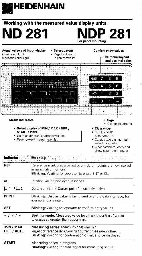
There are three ways to output data:
l Press the MOD key until the PRINT indicator blinks, and start data output with the ENT key; or
p Input the command Ctrl B over the RXD input; 01 l Input a latch command over the D-sub connection EXT.
A connecting cable (to a PC, for example) is available from HEIDENHAIN (Id:Nr. 274 545 ..I: cable length up to 20 m 166 ftl.
Operating parameters for data output: P50. P51
Wiring and pin layout
CHASSIS GND: Chassis Ground; TXD: Transmitted Data; RXD: Received Data; RTS: Request To Send: CTS: Clear To Send; DSR: Data Set Ready; SIGNAL GND: Signal Ground; DTR: Data Terminal Ready
TXD. RXD -3v to -15V +3Vto+15V
RTS, CTS, DSR, DTR +3V to +I 5V -3v to -15v
_,,a* Format
_.,/ ASCII code
Data word 1 start bit, 7 data bits, parity bit (even parity), 2 stop bits
Control characters Start STX, interrupt: DC3. resume: DC1
sequence l Sign l Numerical value with decimal point l Blank space l Unit (blank space = mm, ’ = inches, ? = error) l Comparison result I<, >, =; ! if PI8 > P19) or blank space l Meas. series (S = MIN. A = ACTL, G = MAX, D = DIFF) 01
blank space l Carriage return l Line feed
The duration of data transfer depends on the selected baud rate and the number of additional line feeds. The longest times will be encountered when a DIFF series is running.
Latch sianal Ctrl B EXTipulsel EXTicontacti PRINT
Storage time <I ms Sl ps s5ms 555ms
Transfer time <58ms <58ms <63ms <113ms
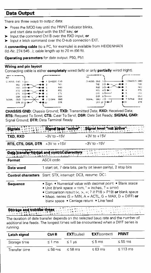
I” 18 Meas. value > upper sorting limit (P19)
17 Meas. value < lower sorting limit (P18)
19 Errorisee “Error Messages”)
14 Display value is zero
2 Reset display to zero
3 Preset display to value from P79
25 Cross over reference marks
4 Ignore reference signal
5 Start measuring series
6 Remote selection of display val. for meas. ser.
7 Display minimum value from meas. series
8 Display maximum value from rneas. series
9 Display MAX-MIN diff. from meas. series
22 Latch (pulse)
10 ov
12 Do not assign
13 Do not assign
11 vacant
20 vacant
21 Vacant
24 Do not assign
Display current meas. value (ACTL): Inputs 7, 8 and 9 are not amvt?, or more than one of these Inputs IS act,ve.
23 Latch (contact)
I
Outputs u s 0.4 v I<lOOmA Us32V I<lOvA
Input signals l Internal pull-up resistor 1 kR l Triggering by make contact against 0 V or
Low level over rrL component . Delay for Zero reset/Preset: t, < 2 ms l Minimum pulse duration for all signals: tmi, 2 55 ms
Output signals l Open collector OUtpUts, active Low A
l Signal output delay: *UB632” t,<60ms
l Zero crossover signal min- imum duration: tot 180 ms
Note that these times will increase if functions are active (such as sorting).
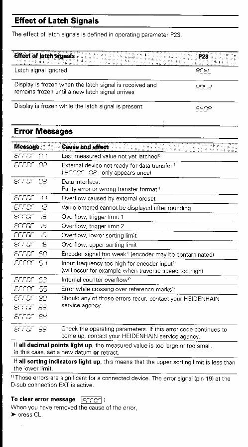
Effect of Latch Signals
The effect of latch signals is defined in operating parameter P23.
Display is frozen when the latch signal is received and remains frozen until a new latch signal arrives
c,‘-,, -, ,,-,,- ,-,
Display is frozen while the latch signal is present
Error Messages
Last measured value not yet latched”
External device not read” for data transfer”
Parity error or wrong transfer format”
Overflow caused by external preset
Value entered cannot be displayed after rounding
Overflow, trigger limit 1
Overflow, trigger limit 2
Overflow, lower sorting limit
Overflow, upper sorting limit
Encoder signal too weak” (encoder may be contaminated)
Input frequency too high for encoder input” (will occur for examplewhen traverse speed too high)
Internal counter overflow”
Error while crossing over reference marks”
Should any of these ermis recur, contact your HEIDENHAIN Service agency
c r ,- nr 93 Check the operating parameters. If this error code continues to come up, contact your HEIDENHAIN service agency.
If all decimal points light up, the measured value is too large or too small. In this case, set a new datum or retract.
If all sorting indicators light up, this means that the upper sortinq limit is less than the lower limit.
“These ewrs are significant for a connected device. The error signal (pin 19) at the D-sub connection EXT is active.
To clear error message m :
When you have removed the cause of the error, l press CL.
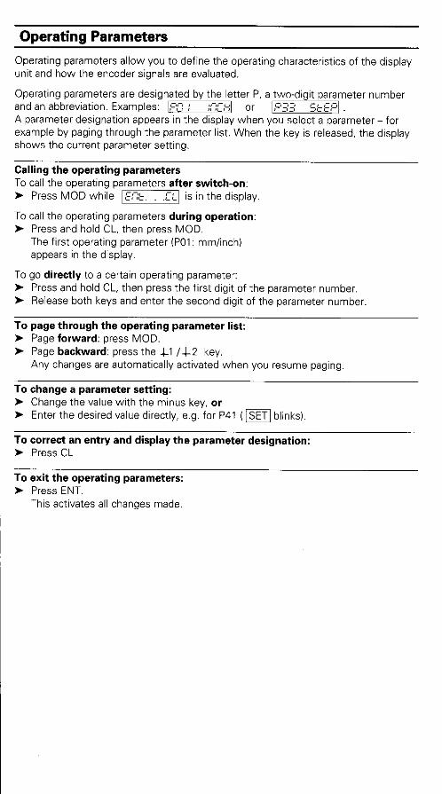
Operating Parameters
Operating parameters allow you to define the operating characteristics of the display unit and how the encoder signals are evaluated.
Operating parameters are designated by the letter P. a two-digit parameter number and an abbreviation. Examples: PZ : ::-;c C’ 0 r ,L,_ij $,&Cf
A parameter designation appears in the display when you select a parameter-for example by paging through the parameter list. When the key is released, the display shows the current parameter setting.
Calling the operating parameters To call the operating parameters after switch-on: t Press MOD while m is in the display.
To call the operating parameters during operation: l Press and hold CL, then press MOD.
The first operating parameter (POl: mm/inch) appears in the display.
To go directly to a certain operating parameter: l Press and hold CL, then press the first digit of the parameter number. l Release both keys and enter the second digit of the parameter number.
To page through the operating parameter list: N Page forward: press MOD. W Page backward: press the Cl /C2 key.
Any changes are automatically activated when you resume paging.
To change a parameter setting: l Change the value with the minus key, or l Enter the desired value directly, e.g. for P41 (m blinks).
To correct an entry and display the parameter designation: F Press CL
To exit the operating parameters: N Press ENT.
This activates all changes made.
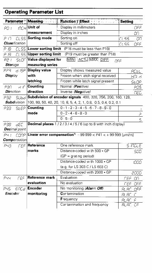
ODerating Parameter List
, ,~ , ,~ ,~ ,
latching Frozen while latch signal present -If- CII p3;:; j ;;- Counting Normal iPositive) ___
CL’;.::, Direction direction Inverse (Negative) ,cc,
- ,L’z;cc’ SC;& Subdivision of encoder signals 400, 320, 256, ZOO, 160, 128,
Subdivision 1100. 80, 50,40,20, 10, 8. 5.4, 2, 1.0.8, 0.5.0.4. 0.2.0.1 F,kE;:’ Counting r 3 1, 0-1-2-3-4-5~6-7-8-9-0 1
mode 0-2-4-6-8-O I 1, I
O-5-0 5 p 35; ,&: Decimal places 1 I2 I3 / 4 I5 I6 (up to 8 with inch display)
Decimal point p; ; =z;-;P Linear error compensation” - 99 999 < P41 < + 99 999 [pm/ml
Compensation ;-:;I Reference One reference mark si, ,/ 1111-1 ,-, ,- ,. c
marks Distance-coded with 500 - GP -ICIY IGP = grating period)
Distance-coded with 1000 * GP
kg. for LS 303 C / LS 603 C)
Distance-coded with 2000 - GP ,aqc: :-:,c Reference mark Evaluation
evaluation No evaluation . _ --- ;-‘Ly cm *I .I Encoder ,-, ,L,-, No monitoring (Alarm Off) Encoder monitoring Contamination
Frequency
Contamination and frequency
,c,c,c,
c ClClCl

ODeratina Parameter List - c0nt-d.
REF over D-sub connection EXT
11 Determine entry value for P41 Example: Displayed measuring length Ld = 620.000 mm
Actual length (determined with, for example, the VM 101 comparator system from HEIDENHAIN) L, = 619.876 mm Length difference AL = L, - Ld = -124 pm Camp. factor k: k = AL 1 Ld = -124 lrn / 0.62 m = -200 [~.lm/m]
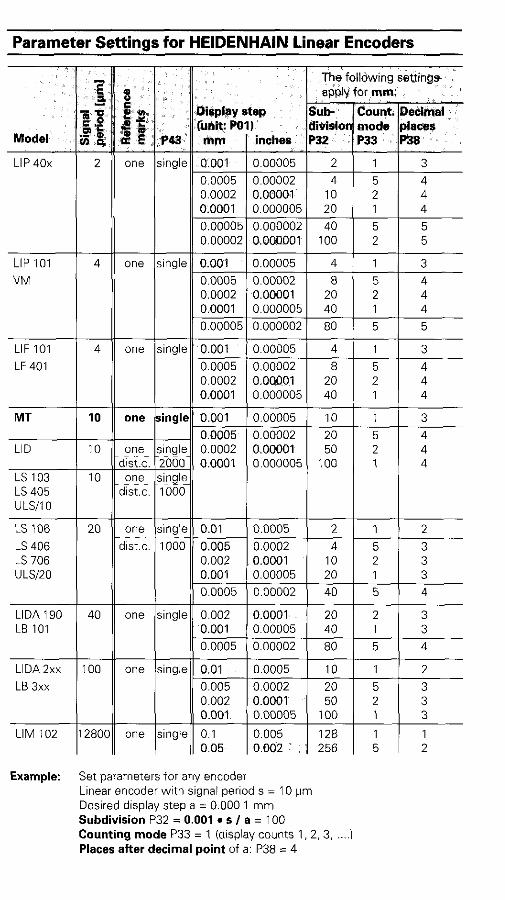
Parameter Settings for HEIDENHAIN Linear Encoders
LIP 101 4
WV
LIFIOI 4
LF401
MT 10
LID IO
LS103 10 LS405 ULSilO
LS106 20
LS406 LS706 ULSIZO
LIDAlSO 40 LB101
LlDAZxx 100
LB3xx
LIM 102 128OC
0.0005 0.00002 80 5 4
one single 0.01 0.0005 10 1 2
0.005 0.0002 20 5 3 0.002 0.0001 50 2 3 0.001 0.00005 100 1 3
one single 0.1 0.005 128 1 1 0.05 0.002 256 5 2
Setparametersfor any encoder Linear encoder with signal periods = 10 pm Desired display step a = 0.000 1 mm Subdivision P32 = 0.001 l s I a = 100 Counting mode P33 = 1 (display camts 1, 2.3, ..-I Places after decimal point of a: P38 = 4

ND 281: Rear Panel
Data interface v.24, RS~232-c
Power switch
D-sub connection EXT
Ground terminal Input for HEIDENHAIN linear encoders with sinusoidal output signals UpA,, to 16 1.1Appl. connecting cable max. 30 m (100 ftl, max. permissible input frequency 100 kHz
and X41~interfacesoomply with the recomme~~ati,on~~in for separati,op from liri& ptier. , I
NDP 281: Front and Rear Panel
L ”
I : .:, $
Dimensions:
Cutout for front panel: 259+0.5 * 88+0.5 mm Mounting depth minimum 237 mm
Xl input for HEIDENHAIN
linear encoder with sinusoidal
output signals (see above)
Power /“put Data interface
RS-232-C / V.24
Ground terminal D-sub connection EXT

ND 281: Installation
You can mount the display unit to a flat surface with M4 screws.
Display units can also be stacked. Adhesive inserts (included in deliveryi prevent the units from sliding.
Power Sumh and Connection
Primary-clocked power supply, tolerates overvoltage in accordance with VDE 0160. 5.88. Overvoltage tolerance class 2. Voltage range 100 V to 240 V (-15% to +I 0 %) Frequency 48 Hz to 62 Hz Power consumption typ. 8 W Line fuse F 1 A (in unit) Minimum cross-section of power cable: 0.75 mm2
Power connection - NDP 281 The NDP 281 has a clamp IX 51) on its rear panel.
x 51
ml
cp&
Ambient Conditions
Temperature range Operation: 0°C to +45”C (32°F to 1 13°F) Storage: -30°C to +7O”C (-32°F to 158°F)
Rel. humiditv Annual averaae: < 75%: maximum: < 90%
Weight 1.5 kg
DR.JDHANNES HEIDENHAIN GrnbH Dr,Johannes~HeidenhainStraRe 5 D-83301 Traunreut. Deutschland se (08689) 31~0 ml(O8669) 5061 fS Service (08669) 31-1272 S? TNGService (08889) 31-1446 m(O8669) 9899