
Working with T3 and T1: Technology, Troubleshooting … with T3 and T1: Technology, Troubleshooting...
22
1 Working with T3 and T1: Technology, Troubleshooting and Fault Location Sunrise Telecom . . . A Step Ahead
Transcript of Working with T3 and T1: Technology, Troubleshooting … with T3 and T1: Technology, Troubleshooting...
1
Working with T3 and T1:
Technology, Troubleshooting and Fault Location
Sunrise Telecom . . . A Step Ahead
1
T3 Transmission
T3 Usage
T3s are used for a variety of purposes. They are widely embedded in the network
transport architecture as a convenient means of carrying 672 voice channels in
one circuit. Newer T3 applications include the transport of broadcast-quality
video, ATM (Asynchronous Transfer Mode) physical layer connections, and
supercomputer direct links.
T3 Services
Telephone companies are now selling T3 point-to-point circuits as a highly
profitable service alternative. T3s are purchased by interexchange resellers who
make a business out of slicing up their bandwidth into lower-rate pieces and
selling it at a higher per unit cost. Interexchange companies sometimes
purchase their local access interfaces at DS3 rates for speed and simplicity in
installation. Or, these interexchange companies may be selling T3 national
interconnection services to large end users, and may be purchasing the local
distribution of the T3 to the customer premises through the local telephone
company. Bypass companies can sell T3 radio access in metropolitan areas in
competition with land-based T3 service by local telephone companies. The ever
increasing appetite for digital bandwidth in combination with the merging of
multimedia applications with communications are driving a strong growth in
the delivery of T3 service.
T3 Network Elements
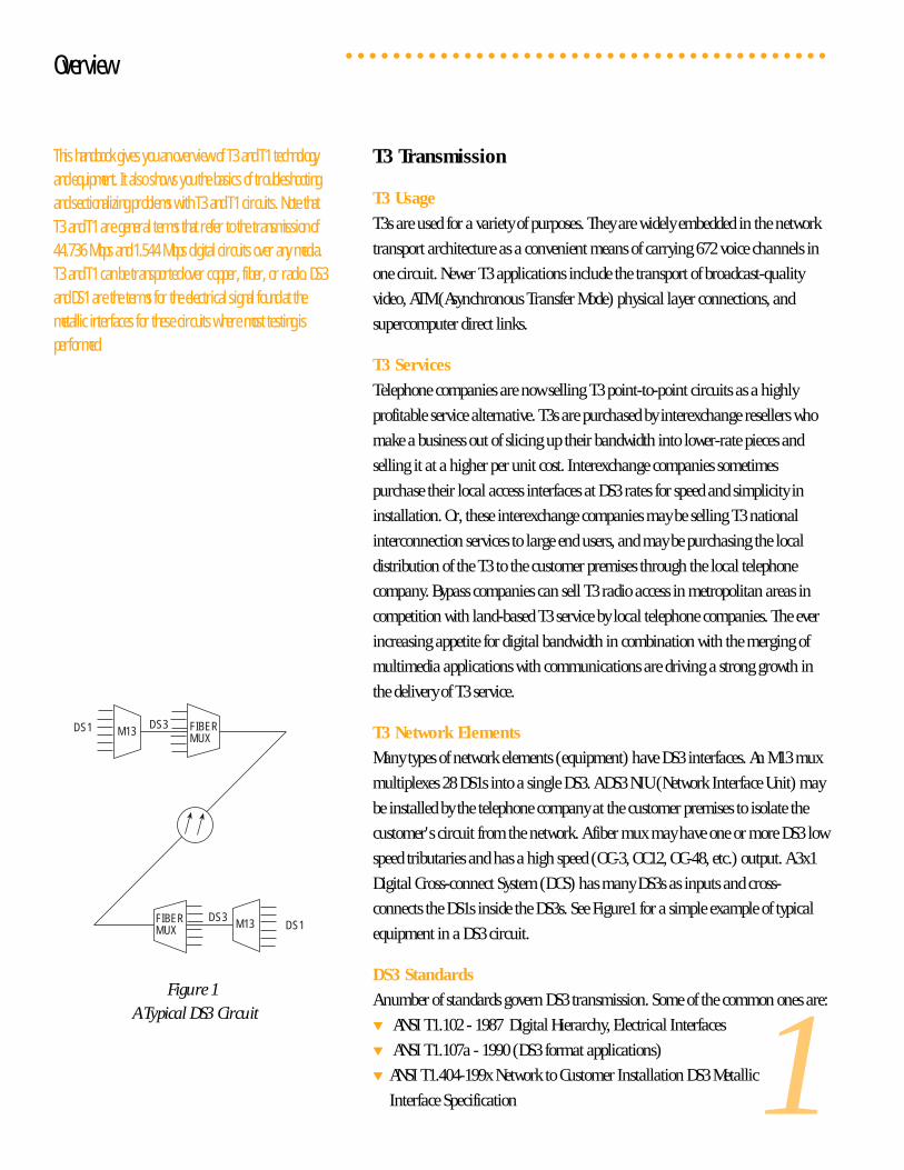
Many types of network elements (equipment) have DS3 interfaces. An M13 mux
multiplexes 28 DS1s into a single DS3. A DS3 NIU (Network Interface Unit) may
be installed by the telephone company at the customer premises to isolate the
customer's circuit from the network. A fiber mux may have one or more DS3 low
speed tributaries and has a high speed (OC-3, OC12, OC-48, etc.) output. A 3x1
Digital Cross-connect System (DCS) has many DS3s as inputs and cross-
connects the DS1s inside the DS3s. See Figure1 for a simple example of typical
equipment in a DS3 circuit.
DS3 Standards
A number of standards govern DS3 transmission. Some of the common ones are:
▼ ANSI T1.102 - 1987 Digital Hierarchy, Electrical Interfaces
▼ ANSI T1.107a - 1990 (DS3 format applications)
▼ ANSI T1.404-199x Network to Customer Installation DS3 Metallic
Interface Specification
DS1 DS3M13 FIBER
MUX
DS3 M13FIBERMUX DS1
Figure 1
A Typical DS3 Circuit
○ ○ ○ ○ ○ ○ ○ ○ ○ ○ ○ ○ ○ ○ ○ ○ ○ ○ ○ ○ ○ ○ ○ ○ ○ ○ ○ ○ ○ ○ ○ ○ ○ ○ ○ ○ ○ ○ ○ ○ ○
Overview
This handbook gives you an overview of T3 and T1 technologyand equipment. It also shows you the basics of troubleshootingand sectionalizing problems with T3 and T1 circuits. Note thatT3 and T1 are general terms that refer to the transmission of44.736 Mbps and 1.544 Mbps digital circuits over any media.T3 and T1 can be transported over copper, fiber, or radio. DS3and DS1 are the terms for the electrical signal found at themetallic interfaces for these circuits where most testing isperformed.
2
▼ Bellcore TR-TSY-000009 Asynchronous Digital Multiplexes - Requirements
and Objectives
▼ AT&T TR 62415 Access Specification for High Capacity (DS1/DS3) Dedicated
Digital Services
DS3 Signal
A DS3 signal consists of digital data transmitted at 44.736 megabits per second
(Mbps), plus or minus 20 parts per million. Coaxial cables carry the DS3 signal,
with the actual signal found on the center conductor. The outer conductor is
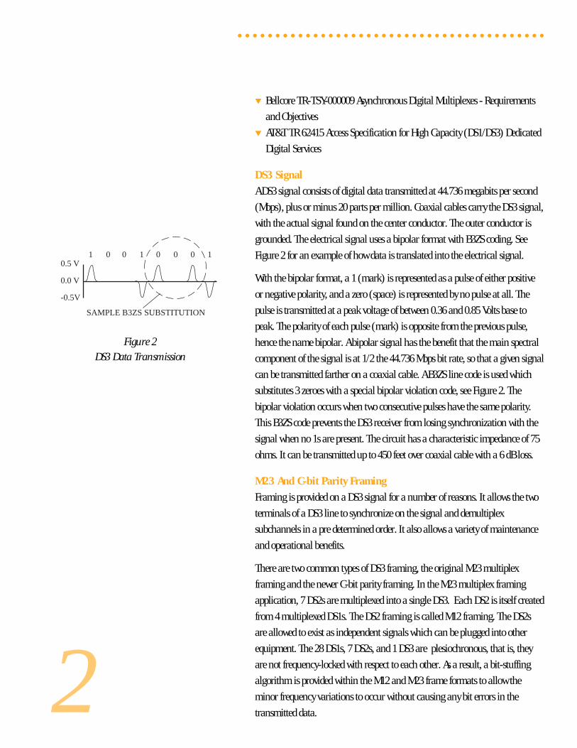
grounded. The electrical signal uses a bipolar format with B3ZS coding. See
Figure 2 for an example of how data is translated into the electrical signal.
With the bipolar format, a 1 (mark) is represented as a pulse of either positive
or negative polarity, and a zero (space) is represented by no pulse at all. The
pulse is transmitted at a peak voltage of between 0.36 and 0.85 Volts base to
peak. The polarity of each pulse (mark) is opposite from the previous pulse,
hence the name bipolar. A bipolar signal has the benefit that the main spectral
component of the signal is at 1/2 the 44.736 Mbps bit rate, so that a given signal
can be transmitted farther on a coaxial cable. A B3ZS line code is used which
substitutes 3 zeroes with a special bipolar violation code, see Figure 2. The
bipolar violation occurs when two consecutive pulses have the same polarity.
This B3ZS code prevents the DS3 receiver from losing synchronization with the
signal when no 1s are present. The circuit has a characteristic impedance of 75
ohms. It can be transmitted up to 450 feet over coaxial cable with a 6 dB loss.
M23 And C-bit Parity Framing
Framing is provided on a DS3 signal for a number of reasons. It allows the two
terminals of a DS3 line to synchronize on the signal and demultiplex
subchannels in a pre determined order. It also allows a variety of maintenance
and operational benefits.
There are two common types of DS3 framing, the original M23 multiplex
framing and the newer C-bit parity framing. In the M23 multiplex framing
application, 7 DS2s are multiplexed into a single DS3. Each DS2 is itself created
from 4 multiplexed DS1s. The DS2 framing is called M12 framing. The DS2s
are allowed to exist as independent signals which can be plugged into other
equipment. The 28 DS1s, 7 DS2s, and 1 DS3 are plesiochronous, that is, they
are not frequency-locked with respect to each other. As a result, a bit-stuffing
algorithm is provided within the M12 and M23 frame formats to allow the
minor frequency variations to occur without causing any bit errors in the
transmitted data.
○ ○ ○ ○ ○ ○ ○ ○ ○ ○ ○ ○ ○ ○ ○ ○ ○ ○ ○ ○ ○ ○ ○ ○ ○ ○ ○ ○ ○ ○ ○ ○ ○ ○ ○ ○ ○ ○ ○ ○ ○
Figure 2DS3 Data Transmission
1 0 0 1 0 0 0 10.5 V
0.0 V
-0.5V
SAMPLE B3ZS SUBSTITUTION
3
C-bit parity framing was created because DS2s typically do not need to exist
independently with varying frequencies. Instead, most commercial multiplex
equipment operates in an M13 mode, multiplexing 28 DS1s directly into a DS3.
DS2 signals are still multiplexed within the DS3, but the DS2s' timing is
frequency-locked to the DS3 which frees up the M23 stuff bits to be used for
other purposes, providing additional benefits to users.
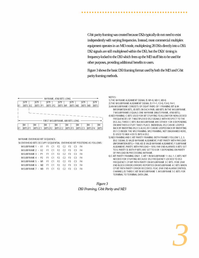
Figure 3 shows the basic DS3 framing format used by both the M23 and C-bit
parity framing methods.
○ ○ ○ ○ ○ ○ ○ ○ ○ ○ ○ ○ ○ ○ ○ ○ ○ ○ ○ ○ ○ ○ ○ ○ ○ ○ ○ ○ ○ ○ ○ ○ ○ ○ ○ ○ ○ ○ ○ ○ ○
Figure 3DS3 Framing, C-bit Parity and M23
84 84 84 84 84 84 84 84X1 BITS F1 BITS C1 BITS F2 BITS C2 BITS F3 BITS C3 BITS F4 BITS
FIRST M-SUBFRAME, 680 BITS LONG
679 679 679 679 679 679 679X1 BITS X2 BITS P1 BITS P2 BITS M1 BITS M2 BITS M3 BITS
M-FRAME, 4760 BITS LONG
M-FRAME OVERHEAD BIT SEQUENCE.
56 OVERHEAD BITS OCCUPY SEQUENTIAL OVERHEAD BIT POSITIONS AS FOLLOWS:
M-SUBFRAME 1 - X1 F1 C1 F2 C2 F3 C3 F4
M-SUBFRAME 2 - X2 F1 C1 F2 C2 F3 C3 F4
M-SUBFRAME 3 - P1 F1 C1 F2 C2 F3 C3 F4
M-SUBFRAME 4 - P2 F1 C1 F2 C2 F3 C3 F4
M-SUBFRAME 5 - M1 F1 C1 F2 C2 F3 C3 F4
M-SUBFRAME 6 - M2 F1 C1 F2 C2 F3 C3 F4
M-SUBFRAME 7 - M3 F1 C1 F2 C2 F3 C3 F4
NOTES:1) THE M-FRAME ALIGNMENT SIGNAL IS M1=0, M2=1, M3=0.2) THE M-SUBFRAME ALIGNMENT SIGNAL IS F1=1, F2=0, F3=0, F4=1.3) AN M-SUBFRAME CONSISTS OF EIGHT PAIRS OF 1 FRAMING BIT & 84
INFORMATION BITS, 85 BITS IN EACH PAIR, 680 BITS IN THE M-SUBFRAME.7 M-SUBFRAMES EQUALS ONE M-FRAME (MULTI FRAME, 4760 BITS).
4) M23 FRAMING: C-BITS USED FOR BIT STUFFING TO ALLOW FOR NON-LOCKEDFREQUENCIES OF 7 MULTIPLEXED DS2 SIGNALS WITH RESPECT TO THEDS3. ALL THREE C BITS IN A M-SUBFRAME ARE EITHER 1 OR 0 DEPENDINGON WHETHER A STUFF TAKES PLACE. INDIVIDUAL DS2 CAN BE LOOPEDBACK BY INVERTING DS2 C3. ALSO, DS1 CAN BE LOOPED BACK BY INVERTINGDS1 C3 INSIDE THE M12 FRAMING. M12 FRAMING, NOT DIAGRAMED HERE,IS USED TO MUX 4 DS1S INTO A DS2.
5) M23 FRAMING AND C-BIT PARITY FRAMING: BOTH FRAMES FOLLOW 1, 2, 3.IDLE SIGNAL IS VALID M-FRAME ALIGNMENT, P-BIT PARITY WITH PAYLOAD(INFORMATION BITS) = 1100. AIS IS VALID M-FRAME ALIGNMENT, F SUBFRAMEALIGNMENT, PARITY, WITH PAYLOAD = 1010. FAR END ALARM IS X-BITS SETTO 0. PARITY IS BOTH P-BITS ARE SET TO 0 OR 1 DEPENDING ON PARITYOF PAYLOAD IN PRECEEDING M-FRAME.
6) C-BIT PARITY FRAMING ONLY: C-BIT 1 IN M-SUBFRAME 1 = ALL 1. C-BITS NOTNEEDED FOR STUFFING BECAUSE DS2 FREQUENCY LOCKED TO DS3FREQUENCY. CP-BIT PATH PARITY ON M SUBFRAME 3 C BITS. FEBE (FAREND BLOCK ERROR) ERRORS REPORTED ON M SUBFRAME 4 C BITS WHENCP BIT PATH PARITY ERROR RECEIVED. FEAC (FAR END ALARM CONTROLCHANNEL) IS THIRD C-BIT IN M SUBFRAME 1. M-SUBFRAME 5 C-BITS FORTERMINAL TO TERMINAL DATA LINK.
4
Figure 4DS3 Idle Signal
Figure 5Generation of DS3 AIS
Figure 6
Generation of DS3 Yellow
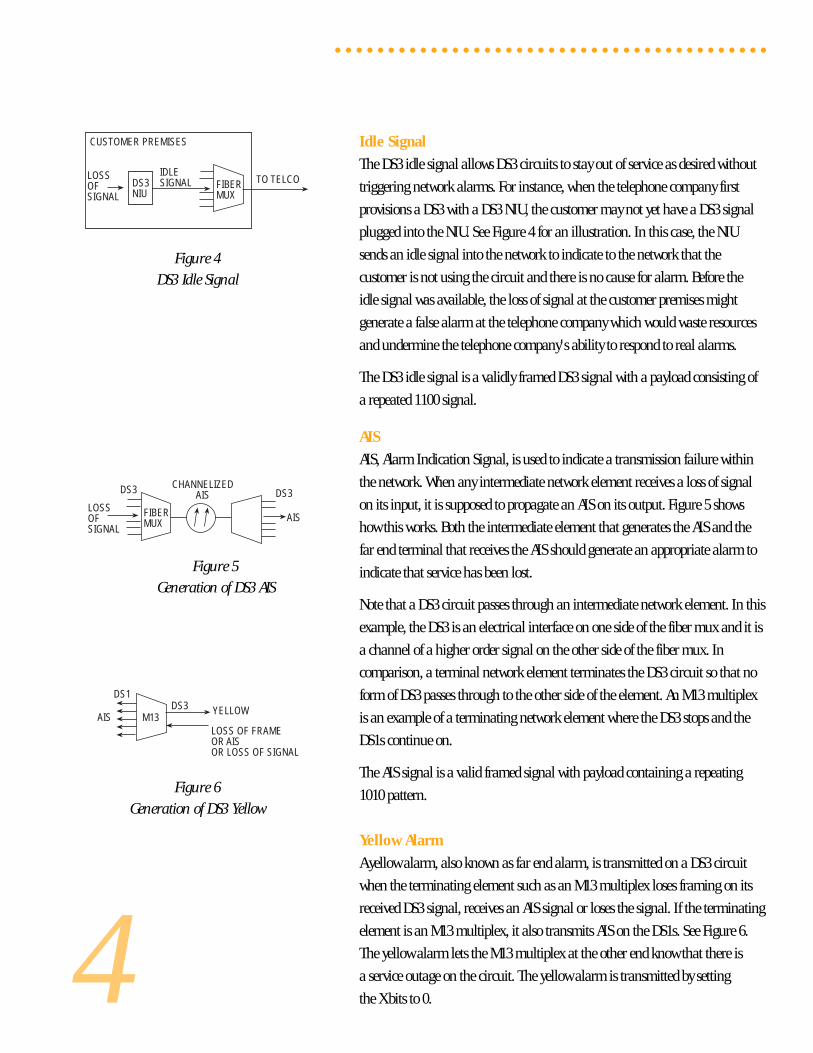
Idle Signal
The DS3 idle signal allows DS3 circuits to stay out of service as desired without
triggering network alarms. For instance, when the telephone company first
provisions a DS3 with a DS3 NIU, the customer may not yet have a DS3 signal
plugged into the NIU. See Figure 4 for an illustration. In this case, the NIU
sends an idle signal into the network to indicate to the network that the
customer is not using the circuit and there is no cause for alarm. Before the
idle signal was available, the loss of signal at the customer premises might
generate a false alarm at the telephone company which would waste resources
and undermine the telephone company's ability to respond to real alarms.
The DS3 idle signal is a validly framed DS3 signal with a payload consisting of
a repeated 1100 signal.
AIS
AIS, Alarm Indication Signal, is used to indicate a transmission failure within
the network. When any intermediate network element receives a loss of signal
on its input, it is supposed to propagate an AIS on its output. Figure 5 shows
how this works. Both the intermediate element that generates the AIS and the
far end terminal that receives the AIS should generate an appropriate alarm to
indicate that service has been lost.
Note that a DS3 circuit passes through an intermediate network element. In this
example, the DS3 is an electrical interface on one side of the fiber mux and it is
a channel of a higher order signal on the other side of the fiber mux. In
comparison, a terminal network element terminates the DS3 circuit so that no
form of DS3 passes through to the other side of the element. An M13 multiplex
is an example of a terminating network element where the DS3 stops and the
DS1s continue on.
The AIS signal is a valid framed signal with payload containing a repeating
1010 pattern.
Yellow Alarm
A yellow alarm, also known as far end alarm, is transmitted on a DS3 circuit
when the terminating element such as an M13 multiplex loses framing on its
received DS3 signal, receives an AIS signal or loses the signal. If the terminating
element is an M13 multiplex, it also transmits AIS on the DS1s. See Figure 6.
The yellow alarm lets the M13 multiplex at the other end know that there is
a service outage on the circuit. The yellow alarm is transmitted by setting
the X bits to 0.
○ ○ ○ ○ ○ ○ ○ ○ ○ ○ ○ ○ ○ ○ ○ ○ ○ ○ ○ ○ ○ ○ ○ ○ ○ ○ ○ ○ ○ ○ ○ ○ ○ ○ ○ ○ ○ ○ ○ ○ ○
FIBERMUX
CUSTOMER PREMISES
DS3NIU
TO TELCOIDLESIGNAL
LOSSOFSIGNAL
FIBERMUX
DS3 CHANNELIZEDAIS
LOSSOFSIGNAL
AIS
DS3
M13DS3
AISLOSS OF FRAMEOR AISOR LOSS OF SIGNAL
DS1
YELLOW
5
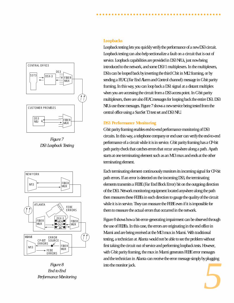
Loopbacks
Loopback testing lets you quickly verify the performance of a new DS3 circuit.
Loopback testing can also help sectionalize a fault on a circuit that is out of
service. Loopback capabilities are provided in DS3 NIUs, just now being
introduced to the network, and some DS3/1 multiplexers. In the multiplexers,
DS1s can be looped back by inverting the third C bit in M12 framing, or by
sending a FEAC (Far End Alarm and Control channel) message in C-bit parity
framing. In this way, you can loop back a DS1 signal at a distant multiplex
when you are accessing the circuit from a DS3 access point. In C-bit parity
multiplexers, there are also FEAC messages for looping back the entire DS3. DS3
NIUs use these messages. Figure 7 shows a new service being tested from the
central office using a SunSet T3 test set and DS3 NIU.
DS3 Performance Monitoring
C-bit parity framing enables end-to-end performance monitoring of DS3
circuits. In this way, a telephone company or end user can verify the end-to-end
performance of a circuit while it is in service. C-bit parity framing has a CP-bit
path parity check that catches errors that occur anywhere along a path. A path
starts at one terminating element such as an M13 mux and ends at the other
terminating element.
Each terminating element continuously monitors its incoming signal for CP-bit
path errors. If an error is detected on the incoming DS3, the terminating
elements transmits a FEBE (Far End Block Error) bit on the outgoing direction
of the DS3. Network monitoring equipment located anywhere along the path
then measures these FEBEs in each direction to gauge the quality of the circuit
while it is in service. They can measure the FEBE even if it is impossible for
them to measure the actual errors that occurred in the network.
Figure 8 shows how a bit-error-generating impairment can be observed through
the use of FEBEs. In this case, the errors are originating in the end office in
Miami and are being received at the M13 mux in Miami. With traditional
testing, a technician at Atlanta would not be able to see the problem without
first taking the circuit out of service and performing loopback tests. However,
with C-bit parity framing, the mux in Miami generates FEBE error messages
and the technician in Atlanta can receive the error message simply by plugging
into the monitor jack.
○ ○ ○ ○ ○ ○ ○ ○ ○ ○ ○ ○ ○ ○ ○ ○ ○ ○ ○ ○ ○ ○ ○ ○ ○ ○ ○ ○ ○ ○ ○ ○ ○ ○ ○ ○ ○ ○ ○ ○ ○
FIBERMUX
MIAMI
M13
ERRORSOURCE
FEBEERRORS
CP-BITERRORS
FIBERMUX
ATLANTA
DSX-3MONOUT
IN
SST3
FIBERMUX
NEW YORK
M13
FEBEERRORS
FIBERMUX
Figure 8End to End
Performance Monitoring
Figure 7
DS3 Loopback Testing
FIBERMUX
CUSTOMER PREMISES
DS3NIU
FIBERMUX
CENTRAL OFFICE
DSX-3SST3DS3
6
T1 Transmission
T1 Usage
T1s are used for a variety of purposes. They are widely embedded in the network
distribution architecture as a convenient means of reducing cable pair counts
by carrying 24 voice channels in one 4 wire circuit. End users have migrated
their private networks onto leased T1s as a means of reducing their network
operation costs. DS1 is a universal digital access point to traditional digital
networks and newer fiber optic synchronous networks.
T1 Services
Telephone companies are now selling T1 point-to-point circuits in a variety of
formats. Channelized T1s are often sold as a means of connecting PBXs (Private
Branch Exchanges) or ACDs (Automatic Call Distributors) to a central office
switch. In this case, the telephone company may also install and maintain a
channel bank for the customer at their premises. T1 "pipes" are sold to more
sophisticated users who only require point-to-point connectivity of a T1 circuit
from the telephone company.
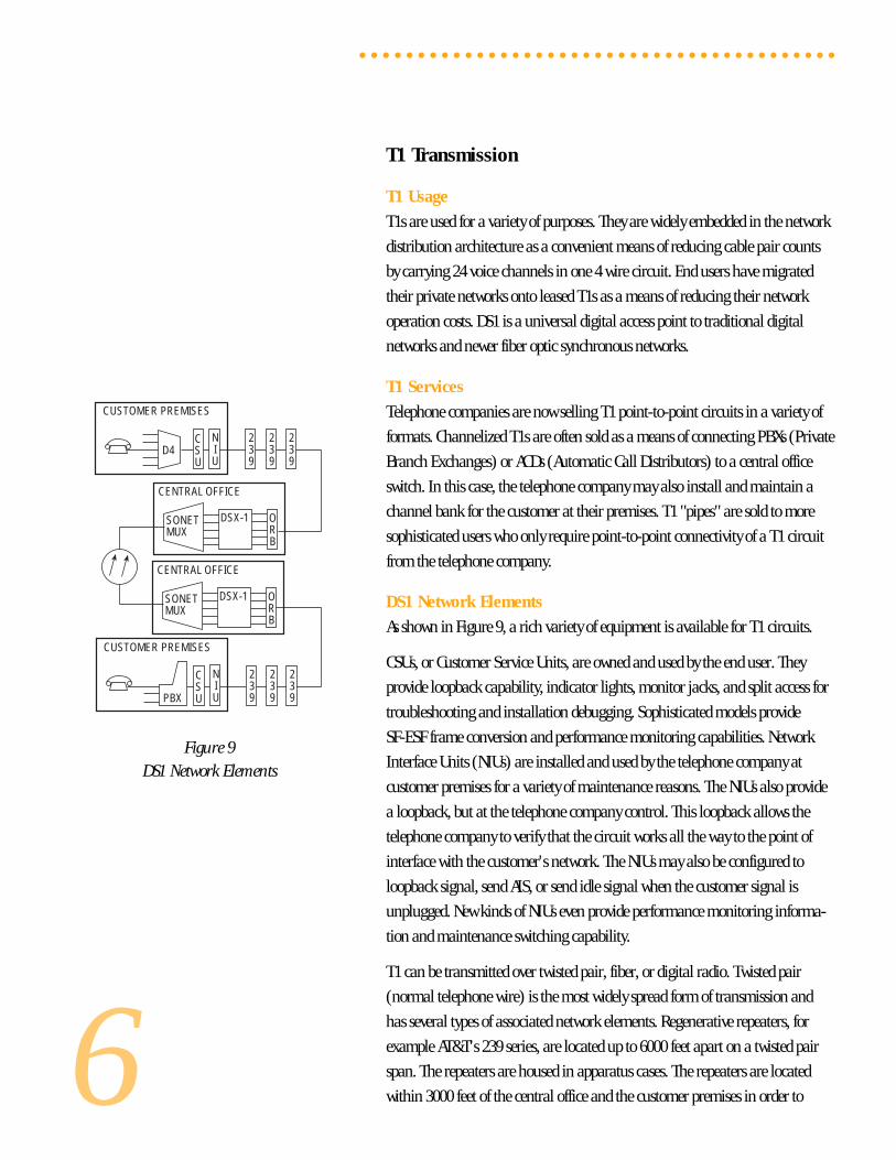
DS1 Network Elements
As shown in Figure 9, a rich variety of equipment is available for T1 circuits.
CSUs, or Customer Service Units, are owned and used by the end user. They
provide loopback capability, indicator lights, monitor jacks, and split access for
troubleshooting and installation debugging. Sophisticated models provide
SF-ESF frame conversion and performance monitoring capabilities. Network
Interface Units (NIUs) are installed and used by the telephone company at
customer premises for a variety of maintenance reasons. The NIUs also provide
a loopback, but at the telephone company control. This loopback allows the
telephone company to verify that the circuit works all the way to the point of
interface with the customer's network. The NIUs may also be configured to
loopback signal, send AIS, or send idle signal when the customer signal is
unplugged. New kinds of NIUs even provide performance monitoring informa-
tion and maintenance switching capability.
T1 can be transmitted over twisted pair, fiber, or digital radio. Twisted pair
(normal telephone wire) is the most widely spread form of transmission and
has several types of associated network elements. Regenerative repeaters, for
example AT&T's 239 series, are located up to 6000 feet apart on a twisted pair
span. The repeaters are housed in apparatus cases. The repeaters are located
within 3000 feet of the central office and the customer premises in order to
○ ○ ○ ○ ○ ○ ○ ○ ○ ○ ○ ○ ○ ○ ○ ○ ○ ○ ○ ○ ○ ○ ○ ○ ○ ○ ○ ○ ○ ○ ○ ○ ○ ○ ○ ○ ○ ○ ○ ○ ○
Figure 9DS1 Network Elements
CSU
D4NIU
CUSTOMER PREMISES
239
239
239
DSX-1SONETMUX
ORB
CENTRAL OFFICE
CSUPBX
NIU
CUSTOMER PREMISES
239
239
239
DSX-1SONETMUX
ORB
CENTRAL OFFICE
7
avoid cross-talk problems when the signal is carried on building wiring. Newer
line repeaters offer loopback capability for faster span sectionalization. Central
office repeaters provide the 60 mA span current used for powering the regenera-
tive repeaters on the span. The central office repeaters may be housed in
Office Repeater Bays (ORBs). Newer central office repeaters automatically adjust
the supplied voltage to adapt to varying numbers of repeaters plugged into
the span. They also may have fractional T1 blocking capability to allow the
telephone company to sell a reduced price T1 that only carries a certain number
of channels. They also may have automated loopback capability and span
power-down/power-up capability.
A variety of equipment is found at the ends of DS1 lines. D4 channel banks are
a traditional form of multiplexer that converts ordinary telephone wires to
64 kbps channels for multiplexing onto a DS1. Newer D4 banks offer a wide
variety of channel plug-ins to handle DDS-style circuits, private line circuits,
and even ISDN. AT&T SLC-96 (SLC is a registered trademark of AT&T) and
SLC-5 systems are commonly found in the Bell environment and were designed
as enhancements to the older D4 style.
M13 multiplexes are a traditional higher-order multiplexer for DS1s. These
units take up to 28 DS1s and multiplex them into a DS3. Note that the DS1
framing and payload still exists inside the DS3 signal, but that the DS1 line
coding is not passed through.
PBXs, class 5 switches (central office switches connected to local subscribers),
and toll switches are often found at the end of T1 lines. These elements use DS1s
as a way of concentrating their connections to local subscribers and interoffice
trunks. The function of these elements is to take supervision and addressing
information from subscribers, set up a call throughout the world network for
the subscriber, connect the subscriber through when the path is set up, and
terminate the call when the subscriber is finished.
A variety of Digital Cross-connect Switches (DCSs) connect to DS1 lines. DCSs
commonly reduce the space required for achieving channel cross-connection,
eliminate the manual labor associated with cross connection, and can provide
amazingly fast computerized rerouting of facilities in the event of a network
outage. The common DCSs are of type 1x0, 1x1, and 3x1. A 1x0 DCS has DS1
ports interfacing the network. Internally it cross-connects DS0s between the
DS1s according to instructions that have been entered in through the adminis-
trative terminal. The 1x0 DCS takes the place of many racks of 1x0 multiplexes
combined with a DSX-0 manual cross-connect bay. A 1x1 DCS is also called an
○ ○ ○ ○ ○ ○ ○ ○ ○ ○ ○ ○ ○ ○ ○ ○ ○ ○ ○ ○ ○ ○ ○ ○ ○ ○ ○ ○ ○ ○ ○ ○ ○ ○ ○ ○ ○ ○ ○ ○ ○
8
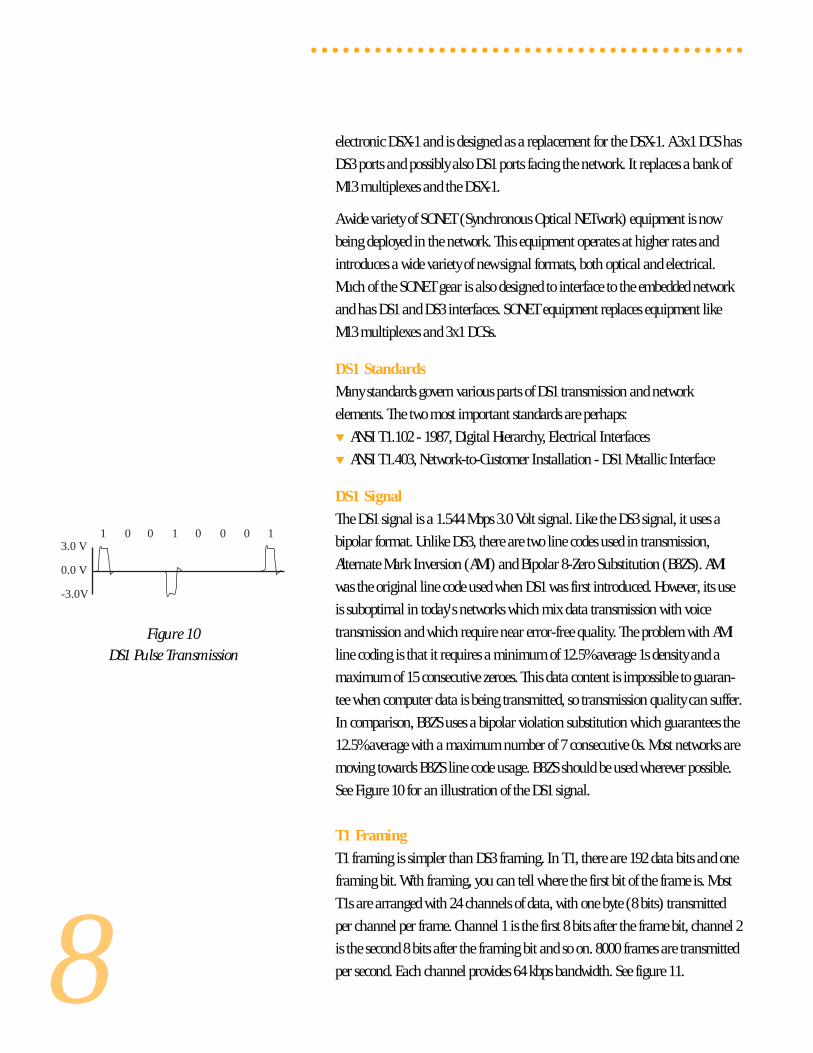
Figure 10DS1 Pulse Transmission
electronic DSX-1 and is designed as a replacement for the DSX-1. A 3x1 DCS has
DS3 ports and possibly also DS1 ports facing the network. It replaces a bank of
M13 multiplexes and the DSX-1.
A wide variety of SONET (Synchronous Optical NETwork) equipment is now
being deployed in the network. This equipment operates at higher rates and
introduces a wide variety of new signal formats, both optical and electrical.
Much of the SONET gear is also designed to interface to the embedded network
and has DS1 and DS3 interfaces. SONET equipment replaces equipment like
M13 multiplexes and 3x1 DCSs.
DS1 Standards
Many standards govern various parts of DS1 transmission and network
elements. The two most important standards are perhaps:
▼ ANSI T1.102 - 1987, Digital Hierarchy, Electrical Interfaces
▼ ANSI T1.403, Network-to-Customer Installation - DS1 Metallic Interface
DS1 Signal
The DS1 signal is a 1.544 Mbps 3.0 Volt signal. Like the DS3 signal, it uses a
bipolar format. Unlike DS3, there are two line codes used in transmission,
Alternate Mark Inversion (AMI) and Bipolar 8-Zero Substitution (B8ZS). AMI
was the original line code used when DS1 was first introduced. However, its use
is suboptimal in today's networks which mix data transmission with voice
transmission and which require near error-free quality. The problem with AMI
line coding is that it requires a minimum of 12.5% average 1s density and a
maximum of 15 consecutive zeroes. This data content is impossible to guaran-
tee when computer data is being transmitted, so transmission quality can suffer.
In comparison, B8ZS uses a bipolar violation substitution which guarantees the
12.5% average with a maximum number of 7 consecutive 0s. Most networks are
moving towards B8ZS line code usage. B8ZS should be used wherever possible.
See Figure 10 for an illustration of the DS1 signal.
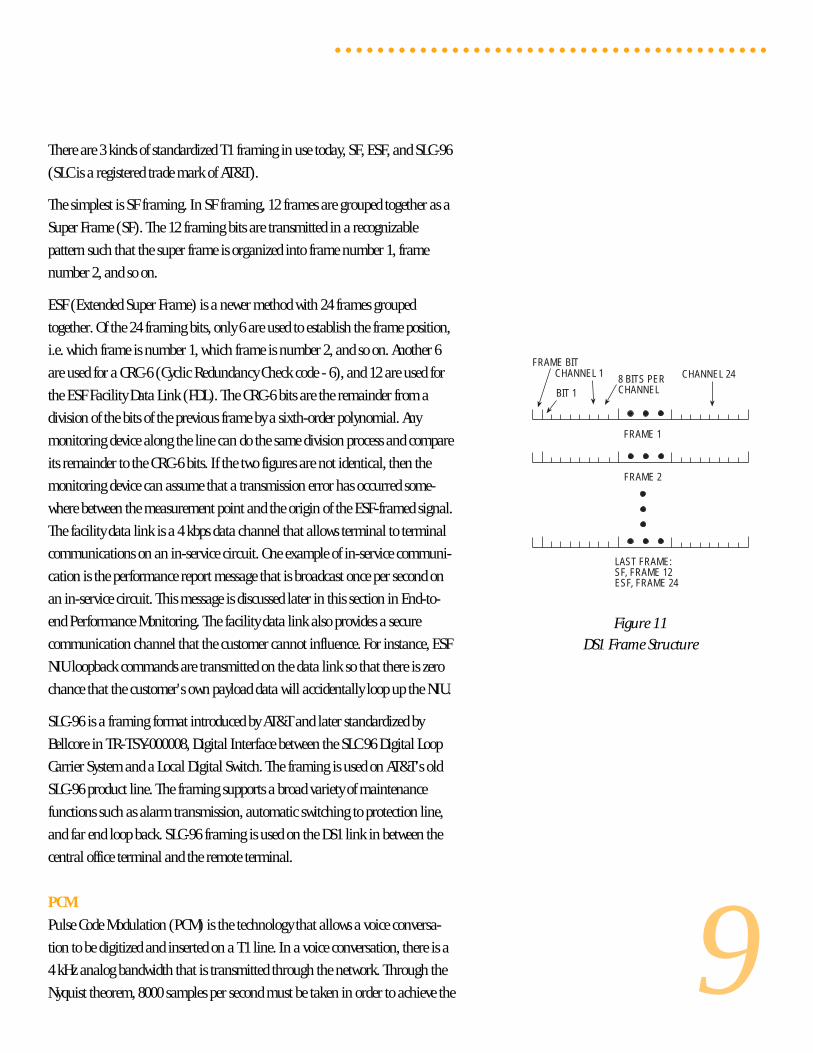
T1 Framing
T1 framing is simpler than DS3 framing. In T1, there are 192 data bits and one
framing bit. With framing, you can tell where the first bit of the frame is. Most
T1s are arranged with 24 channels of data, with one byte (8 bits) transmitted
per channel per frame. Channel 1 is the first 8 bits after the frame bit, channel 2
is the second 8 bits after the framing bit and so on. 8000 frames are transmitted
per second. Each channel provides 64 kbps bandwidth. See figure 11.
○ ○ ○ ○ ○ ○ ○ ○ ○ ○ ○ ○ ○ ○ ○ ○ ○ ○ ○ ○ ○ ○ ○ ○ ○ ○ ○ ○ ○ ○ ○ ○ ○ ○ ○ ○ ○ ○ ○ ○ ○
1 0 0 1 0 0 0 13.0 V
0.0 V
-3.0V
9
There are 3 kinds of standardized T1 framing in use today, SF, ESF, and SLC-96
(SLC is a registered trade mark of AT&T).
The simplest is SF framing. In SF framing, 12 frames are grouped together as a
Super Frame (SF). The 12 framing bits are transmitted in a recognizable
pattern such that the super frame is organized into frame number 1, frame
number 2, and so on.
ESF (Extended Super Frame) is a newer method with 24 frames grouped
together. Of the 24 framing bits, only 6 are used to establish the frame position,
i.e. which frame is number 1, which frame is number 2, and so on. Another 6
are used for a CRC-6 (Cyclic Redundancy Check code - 6), and 12 are used for
the ESF Facility Data Link (FDL). The CRC-6 bits are the remainder from a
division of the bits of the previous frame by a sixth-order polynomial. Any
monitoring device along the line can do the same division process and compare
its remainder to the CRC-6 bits. If the two figures are not identical, then the
monitoring device can assume that a transmission error has occurred some-
where between the measurement point and the origin of the ESF-framed signal.
The facility data link is a 4 kbps data channel that allows terminal to terminal
communications on an in-service circuit. One example of in-service communi-
cation is the performance report message that is broadcast once per second on
an in-service circuit. This message is discussed later in this section in End-to-
end Performance Monitoring. The facility data link also provides a secure
communication channel that the customer cannot influence. For instance, ESF
NIU loopback commands are transmitted on the data link so that there is zero
chance that the customer's own payload data will accidentally loop up the NIU.
SLC-96 is a framing format introduced by AT&T and later standardized by
Bellcore in TR-TSY-000008, Digital Interface between the SLC 96 Digital Loop
Carrier System and a Local Digital Switch. The framing is used on AT&T's old
SLC-96 product line. The framing supports a broad variety of maintenance
functions such as alarm transmission, automatic switching to protection line,
and far end loop back. SLC-96 framing is used on the DS1 link in between the
central office terminal and the remote terminal.
PCM
Pulse Code Modulation (PCM) is the technology that allows a voice conversa-
tion to be digitized and inserted on a T1 line. In a voice conversation, there is a
4 kHz analog bandwidth that is transmitted through the network. Through the
Nyquist theorem, 8000 samples per second must be taken in order to achieve the
Figure 11DS1 Frame Structure
○ ○ ○ ○ ○ ○ ○ ○ ○ ○ ○ ○ ○ ○ ○ ○ ○ ○ ○ ○ ○ ○ ○ ○ ○ ○ ○ ○ ○ ○ ○ ○ ○ ○ ○ ○ ○ ○ ○ ○ ○
FRAME BITCHANNEL 24CHANNEL 1 8 BITS PER
CHANNELBIT 1
FRAME 1
FRAME 2
LAST FRAME:SF, FRAME 12ESF, FRAME 24
10
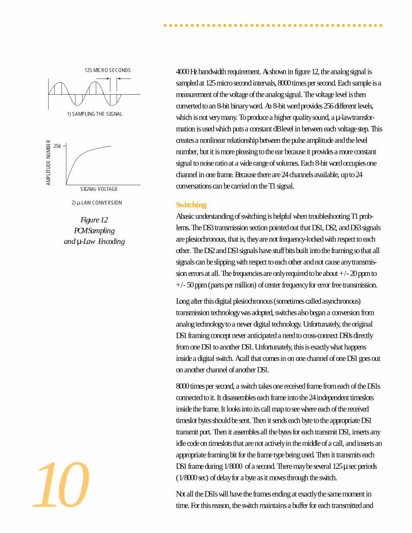
Figure 12PCM Sampling
and µ-Law Encoding
4000 Hz bandwidth requirement. As shown in figure 12, the analog signal is
sampled at 125 micro second intervals, 8000 times per second. Each sample is a
measurement of the voltage of the analog signal. The voltage level is then
converted to an 8-bit binary word. An 8-bit word provides 256 different levels,
which is not very many. To produce a higher quality sound, a µ-law transfor-
mation is used which puts a constant dB level in between each voltage step. This
creates a nonlinear relationship between the pulse amplitude and the level
number, but it is more pleasing to the ear because it provides a more constant
signal to noise ratio at a wide range of volumes. Each 8-bit word occupies one
channel in one frame. Because there are 24 channels available, up to 24
conversations can be carried on the T1 signal.
Switching
A basic understanding of switching is helpful when troubleshooting T1 prob-
lems. The DS3 transmission section pointed out that DS1, DS2, and DS3 signals
are plesiochronous, that is, they are not frequency-locked with respect to each
other. The DS2 and DS3 signals have stuff bits built into the framing so that all
signals can be slipping with respect to each other and not cause any transmis-
sion errors at all. The frequencies are only required to be about +/- 20 ppm to
+/- 50 ppm (parts per million) of center frequency for error free transmission.
Long after this digital plesiochronous (sometimes called asynchronous)
transmission technology was adopted, switches also began a conversion from
analog technology to a newer digital technology. Unfortunately, the original
DS1 framing concept never anticipated a need to cross-connect DS0s directly
from one DS1 to another DS1. Unfortunately, this is exactly what happens
inside a digital switch. A call that comes in on one channel of one DS1 goes out
on another channel of another DS1.
8000 times per second, a switch takes one received frame from each of the DS1s
connected to it. It disassembles each frame into the 24 independent timeslots
inside the frame. It looks into its call map to see where each of the received
timeslot bytes should be sent. Then it sends each byte to the appropriate DS1
transmit port. Then it assembles all the bytes for each transmit DS1, inserts any
idle code on timeslots that are not actively in the middle of a call, and inserts an
appropriate framing bit for the frame type being used. Then it transmits each
DS1 frame during 1/8000 of a second. There may be several 125 µ sec periods
(1/8000 sec) of delay for a byte as it moves through the switch.
Not all the DS1s will have the frames ending at exactly the same moment in
time. For this reason, the switch maintains a buffer for each transmitted and
○ ○ ○ ○ ○ ○ ○ ○ ○ ○ ○ ○ ○ ○ ○ ○ ○ ○ ○ ○ ○ ○ ○ ○ ○ ○ ○ ○ ○ ○ ○ ○ ○ ○ ○ ○ ○ ○ ○ ○ ○
125 MICRO SECONDS
1) SAMPLING THE SIGNAL
256
AMPL
ITU
DE
NU
MBE
R
SIGNAL VOLTAGE
2) µ-LAW CONVERSION
11
received DS1 signal. Each buffer provides an elastic store of bits so that the
switch will always have bits available to transmit or receive at the exact
moment required.
All the DS1s must be received and transmitted at exactly the same frequency, the
frequency that the switch is operating at. Any received DS1 that is going too
slowly will eventually run out of bits in its buffer, because the switch is taking
bits out of the buffer faster than the buffer is being filled by the incoming DS1.
When the buffer becomes empty, the switch must insert extra data in each of the
timeslots that are transmitted on the cross-connected channels. An error has
now occurred because what is transmitted is not the same as what is received.
Likewise, if any received DS1's frequency is higher than the switch, sooner or
later the receive buffer will overflow because bits are coming in faster than they
are being taken out. Once the buffer overflows, some bits that are received will
not be transmitted on the cross-connected channel. An error has again oc-
curred, this time because some data has been lost.
The universal deployment of digital switches has resulted in a massive effort to
synchronize all DS1s so that errors will not occur in switched circuits that use
DS1 for transport.
Synchronization
DS1 circuits should be synchronized to avoid the switching problems described
in the previous paragraph. Minor frequency deviations will cause only pops and
crackles on a voice circuit, however a data circuit can be rendered virtually
useless by the regular errors resulting from frequency slippage. If a DS1 should
be slipping by more than 100 to 300 bps, then a digital switch may even put the
DS1 out of service and declare an alarm.
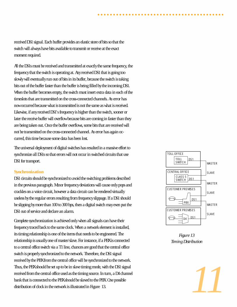
Complete synchronization is achieved only when all signals can have their
frequency traced back to the same clock. When a network element is installed,
its timing relationship is one of the items that needs to be engineered. The
relationship is usually one of master/slave. For instance, if a PBX is connected
to a central office switch via a T1 line, chances are good that the central office
switch is properly synchronized to the network. Therefore, the DS1 signal
received by the PBX from the central office will be synchronized to the network.
Thus, the PBX should be set up to be in slave timing mode, with the DS1 signal
received from the central office used as the timing source. In turn, a D4 channel
bank that is connected to the PBX should be slaved to the PBX. One possible
distribution of clock in the network is illustrated in Figure 13.
○ ○ ○ ○ ○ ○ ○ ○ ○ ○ ○ ○ ○ ○ ○ ○ ○ ○ ○ ○ ○ ○ ○ ○ ○ ○ ○ ○ ○ ○ ○ ○ ○ ○ ○ ○ ○ ○ ○ ○ ○
Figure 13Timing Distribution
D4
CUSTOMER PREMISES
PBX
CUSTOMER PREMISES
CENTRAL OFFICE
TOLL OFFICE
TOLLSWITCH
CLASS 5SWITCH
DS1
DS1
DS1
DS1MASTER
SLAVE
MASTER
SLAVE
MASTER
SLAVE
12
Note that a network element that is slave timed to another network element
may also be the master to other network elements attached to it. Also note that
slave timing is sometimes called loop timing or receive timing - loop timing
because the received timing is looped out the transmitter, and receive timing
because the received signal is used for the timing source.
Another way to be timed is to be internally timed. The advantage of this is
that the element will always be able to generate a signal, so no clock signal
is required. Test sets doing acceptance testing are usually set to internal
timing. Note that internal timing is not acceptable when the test set will be
transmitting toward a switch for nx64 kbps testing when the switch is drawing
its timing from something other than the test set. In this case the test set should
be loop timed.
Supervision
Common T1 framing methods transmit supervisory information through
"robbed bit" signaling. Every 6 frames, the least significant bit in the PCM byte
for every channel is "robbed" and is instead used to transmit signaling informa-
tion. In SF framing, bits in the sixth and twelfth frames are "robbed" to form
the A and B signaling bits for each channel. These bits are interpreted according
to the kind of circuit carried in the channel. For instance, on an E&M circuit
A= 0, B= 0 means that the circuit is idle, (the user is on-hook). A = 1, B = 1
means that the circuit is seized (the user has taken his phone off the hook).
With ESF framing, there are 24 frames grouped together with bit 8 of each
channel in frames 6, 12, 18, and 24 as the ABCD signaling bits. Most ESF
signaling is identical to SF signaling - the C and D bits are copies of the
A and B bits.
SLC-96 supervision is handled via the SLC-96 data link.
Addressing
Addressing is the process of sending a telephone subscriber address for the
purpose of setting up a call. The oldest addressing technique in use today is
pulse dialing. With pulse dialing, your phone goes on-hook and off-hook 10
times per second in order to dial a given number. For example, to dial a 7, you
start out in the off-hook condition, then you go on-hook / off-hook 7 times.
This is the technique that old rotary dial phones use. This addressing informa-
tion is transmitted through a T1 line by toggling the A and B bits from the off-
hook state to the on-hook state at a rate of 10 times per second. This sort of
addressing is now commonly used in switched 56 services.
○ ○ ○ ○ ○ ○ ○ ○ ○ ○ ○ ○ ○ ○ ○ ○ ○ ○ ○ ○ ○ ○ ○ ○ ○ ○ ○ ○ ○ ○ ○ ○ ○ ○ ○ ○ ○ ○ ○ ○ ○
13
MF, Multi Frequency, is an addressing technique used for interoffice signaling
in the telephone network. It uses a group of frequencies in pairs to form a
single address digit. In addition to supporting the digits 0 through 9, MF offers
many other control codes for specialized network applications like billing,
pay phones, etc.
DTMF, Dual Tone Multi Frequency, is the commonly used addressing method
on today's phones. Like MF, it uses pairs of tones to send a digit. Unlike MF, it
uses two separate groups of tones. DTMF supports 16 digits, 0 through 9, #, *,
and A through D.
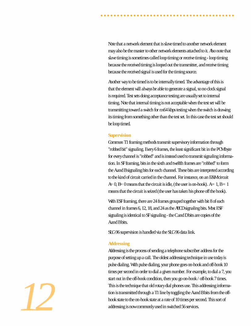
AIS and Yellow Alarms
In DS1, AIS and yellow alarms work just like they do in DS3. An intermediate
network element such as an M13 multiplex, 1x1 DCS, or SONET mux, is
supposed transmit AIS downstream when it receives a loss of signal. The DS1
AIS is an all 1s unframed signal. A terminating network element like a D4
channel bank, PBX, central office switch, or 1x0 DCS should send a yellow
alarm back towards the other end when it receives a loss of frame. Note that a
received AIS and a loss of signal are both loss of frame. Terminating elements
also need to properly condition the DS0s that the DS1 carries when the frame is
lost. For instance, a D4 channel bank is supposed to condition its channel cards
to take them out of service and transmit an appropriate out-of-service signal to
the low speed equipment that is attached. See Figure 14 for diagrams of how the
AIS and yellow alarms are transmitted.
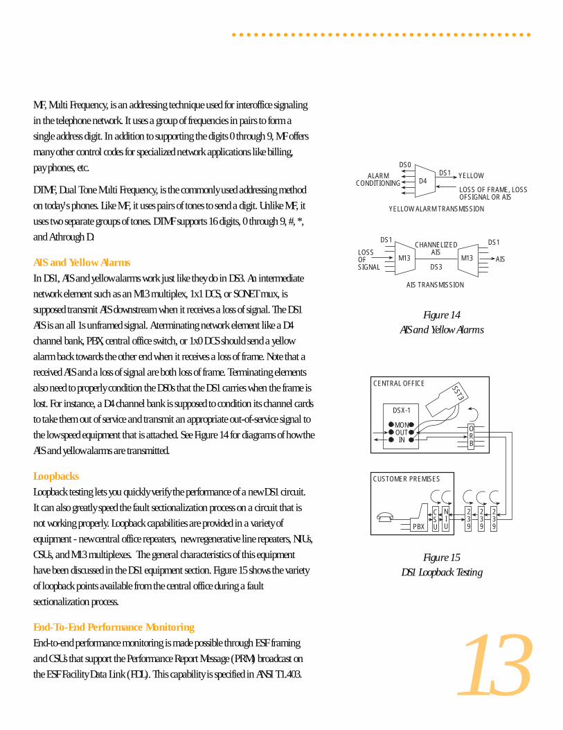
Loopbacks
Loopback testing lets you quickly verify the performance of a new DS1 circuit.
It can also greatly speed the fault sectionalization process on a circuit that is
not working properly. Loopback capabilities are provided in a variety of
equipment - new central office repeaters, new regenerative line repeaters, NIUs,
CSUs, and M13 multiplexes. The general characteristics of this equipment
have been discussed in the DS1 equipment section. Figure 15 shows the variety
of loopback points available from the central office during a fault
sectionalization process.
End-To-End Performance Monitoring
End-to-end performance monitoring is made possible through ESF framing
and CSUs that support the Performance Report Message (PRM) broadcast on
the ESF Facility Data Link (FDL). This capability is specified in ANSI T1.403.
○ ○ ○ ○ ○ ○ ○ ○ ○ ○ ○ ○ ○ ○ ○ ○ ○ ○ ○ ○ ○ ○ ○ ○ ○ ○ ○ ○ ○ ○ ○ ○ ○ ○ ○ ○ ○ ○ ○ ○ ○
Figure 14AIS and Yellow Alarms
Figure 15DS1 Loopback Testing
CSUPBX
NIU
CUSTOMER PREMISES
239
239
239
ORB
CENTRAL OFFICE SST3
DSX-1
MONOUT
IN
M13
DS1CHANNELIZED
AIS
DS3
LOSSOFSIGNAL
AIS
DS1
D4DS1ALARM
CONDITIONINGLOSS OF FRAME, LOSSOFSIGNAL OR AIS
DS0
YELLOW
YELLOW ALARM TRANSMISSION
AIS TRANSMISSION
M13
14
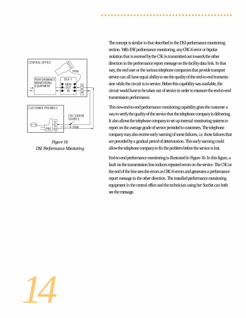
Figure 16
DS1 Performance Monitoring
The concept is similar to that described in the DS3 performance monitoring
section. With ESF performance monitoring, any CRC-6 error or bipolar
violation that is received by the CSU is transmitted out towards the other
direction in the performance report message on the facility data link. In that
way, the end user or the various telephone companies that provide transport
service can all have equal ability to see the quality of the end-to-end transmis-
sion while the circuit is in-service. Before this capability was available, the
circuit would have to be taken out of service in order to measure the end-to-end
transmission performance.
This new end-to-end performance monitoring capability gives the customer a
way to verify the quality of the service that the telephone company is delivering.
It also allows the telephone company to set up internal monitoring systems to
report on the average grade of service provided to customers. The telephone
company may also receive early warning of some failures, i.e. those failures that
are preceded by a gradual period of deterioration. This early warning could
allow the telephone company to fix the problem before the service is lost.
End-to-end performance monitoring is illustrated in Figure 16. In this figure, a
fault on the transmission line induces repeated errors on the service. The CSU at
the end of the line sees the errors as CRC-6 errors and generates a performance
report message in the other direction. The installed performance monitoring
equipment in the central office and the technician using her SunSet can both
see the message.
○ ○ ○ ○ ○ ○ ○ ○ ○ ○ ○ ○ ○ ○ ○ ○ ○ ○ ○ ○ ○ ○ ○ ○ ○ ○ ○ ○ ○ ○ ○ ○ ○ ○ ○ ○ ○ ○ ○ ○ ○
PBX
CUSTOMER PREMISES
CENTRAL OFFICE SST3
DSX-1
MONOUTIN
PERFORMANCEMONITORINGEQUIPMENT O
RB
CSU
CRC ERRORSOURCE
PRM
PRM
15
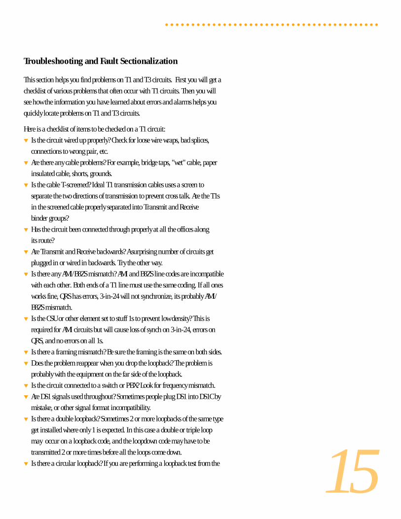
Troubleshooting and Fault Sectionalization
This section helps you find problems on T1 and T3 circuits. First you will get a
checklist of various problems that often occur with T1 circuits. Then you will
see how the information you have learned about errors and alarms helps you
quickly locate problems on T1 and T3 circuits.
Here is a checklist of items to be checked on a T1 circuit:
▼ Is the circuit wired up properly? Check for loose wire wraps, bad splices,
connections to wrong pair, etc.
▼ Are there any cable problems? For example, bridge taps, "wet" cable, paper
insulated cable, shorts, grounds.
▼ Is the cable T-screened? Ideal T1 transmission cables uses a screen to
separate the two directions of transmission to prevent cross talk. Are the T1s
in the screened cable properly separated into Transmit and Receive
binder groups?
▼ Has the circuit been connected through properly at all the offices along
its route?
▼ Are Transmit and Receive backwards? A surprising number of circuits get
plugged in or wired in backwards. Try the other way.
▼ Is there any AMI/B8ZS mismatch? AMI and B8ZS line codes are incompatible
with each other. Both ends of a T1 line must use the same coding. If all ones
works fine, QRS has errors, 3-in-24 will not synchronize, its probably AMI/
B8ZS mismatch.
▼ Is the CSU or other element set to stuff 1s to prevent low density? This is
required for AMI circuits but will cause loss of synch on 3-in-24, errors on
QRS, and no errors on all 1s.
▼ Is there a framing mismatch? Be sure the framing is the same on both sides.
▼ Does the problem reappear when you drop the loopback? The problem is
probably with the equipment on the far side of the loopback.
▼ Is the circuit connected to a switch or PBX? Look for frequency mismatch.
▼ Are DS1 signals used throughout? Sometimes people plug DS1 into DS1C by
mistake, or other signal format incompatibility.
▼ Is there a double loopback? Sometimes 2 or more loopbacks of the same type
get installed where only 1 is expected. In this case a double or triple loop
may occur on a loopback code, and the loopdown code may have to be
transmitted 2 or more times before all the loops come down.
▼ Is there a circular loopback? If you are performing a loopback test from the
○ ○ ○ ○ ○ ○ ○ ○ ○ ○ ○ ○ ○ ○ ○ ○ ○ ○ ○ ○ ○ ○ ○ ○ ○ ○ ○ ○ ○ ○ ○ ○ ○ ○ ○ ○ ○ ○ ○ ○ ○
16
end of a circuit rather than the middle of a circuit, it is possible that the far
end will loop first and then the near end will looback towards the far end,
leaving you shut out of the circuit.
▼ Is there a termination problem? All lines should have only one 100 ohm
termination. Other terminations should be high impedance. If you're not
sure, try TERM, BRIDGE, and MON.
▼ Is the level too low? The received level should be at least -15 dBdsx for
most equipment.
▼ Is there a cross-talk problem? If the signal level is lower than -12 dB, another
signal could be cross-talking onto the received T1 line.
▼ Are repeaters installed? Are they at the right spacing?
▼ Is there a span powering problem? 60 mA span power needs to be delivered to
all repeaters on the span, all repeaters should have their power switches
properly set to LOOP or THRU. The central office automatic span powering
repeater should be delivering the proper voltage to power the span. All the
repeaters before the farthest one away from the central office should be set to
THRU. The farthest repeater or the NIU should be set to LOOP. Too many
repeaters will overload the central office repeater.
▼ Is the NIU span powered? Is that span power provided?
▼ Is the central office repeater transmitting a 6V signal that is not being padded
to 3V before it gets to the next equipment?
▼ Is the test cord broken or dirty? This can cause misleading test results.
▼ Is the test set working properly? This can also cause confusion when
troubleshooting problems. A quick way to check the test set is to loop the test
cord from transmit to receive, checking both the cord and the set at the same
time. Common test set problems are wrong termination (TERM, BRIDGE,
DSXMON), wrong clock setting (INTERNAL is right for most cases), wrong
framing, wrong line code, wrong Nx64 selection, and wrong test pattern.
Fault Sectionalization
Fault sectionalization techniques vary depending on whether the T1 circuit
is in-service or out of service. If it is out of service, then you start from the
middle and loop back the circuit in each direction to see which side has the
problem. Then, you go to the middle of the side that has the problem and do
another loopback in each direction. You repeat this procedure until you find
the problem. See Figure 15 for an illustration of the loopback test. This figure
shows many of the loopbacks that may be available in one direction from
the central office. Note that there also may be DS3 loopbacks available if the
circuit is a DS3 circuit, or DS1 channel loopbacks may be available in higher
order multiplexes.
○ ○ ○ ○ ○ ○ ○ ○ ○ ○ ○ ○ ○ ○ ○ ○ ○ ○ ○ ○ ○ ○ ○ ○ ○ ○ ○ ○ ○ ○ ○ ○ ○ ○ ○ ○ ○ ○ ○ ○ ○
17
If the circuit is in service, non-disruptive performance monitoring techniques
are used. Much can be learned simply by plugging into monitoring jacks and
observing the information. Be sure to plug into the monitor jack for each
direction and look at the results.
The following paragraphs tell you what conclusions you can make from various
results at different monitor points. In the accompanying diagrams, a little
SunSet T3 shows what abnormal conditions it is seeing from its monitor point.
In the diagrams, a triangle indicates a line impairment that is causing steady or
bursty errors. A loss of signal is indicated by a missing signal arrow. If CRC is
listed in the diagram, it will only be seen if the circuit uses ESF framing.
Likewise, If C-bit [parity] error is listed, this is only found if C-bit parity
framing is used.
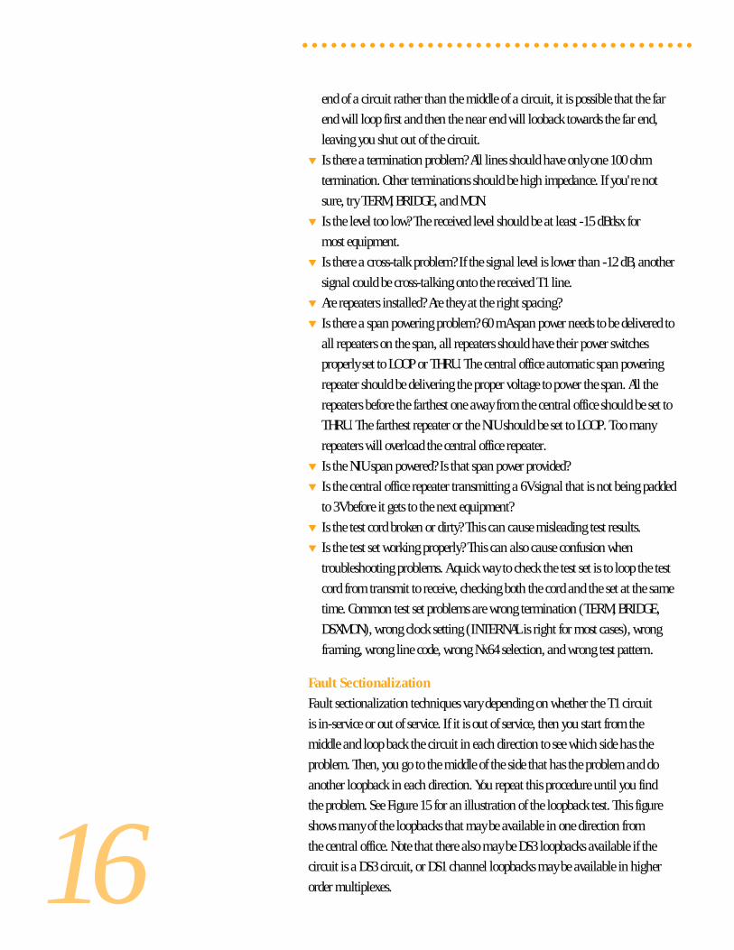
Bipolar Violations And Loss Of Signal
DS1 or DS3 bipolar violations or loss of signal show that the fault is relatively
nearby. DS1 bipolar violations pass through line repeaters, office repeaters and
NIUs, but are stopped by multiplexes, DCSs, switches, signal format changes
(i.e. from optical to electrical, or from radio to electrical) and possibly CSUs.
DS3 bipolar violations indicate that the problem is between the test set and the
nearest DS3 equipment, within a few hundred feet. The DS3 format only exists
at interconnections between equipment. Different formats are used for transmis-
sion over long distances. In comparison, the DS1 electrical signal can transmit-
ted through regenerative line repeaters for hundreds of miles. Thus a DS1
bipolar violation indicates a transmission problem between the test set and the
last multiplex, DCS, or other element that stops bipolar violations.
Figure 17 illustrates the DS1 case.
Figure 18 shows the DS3 case.
○ ○ ○ ○ ○ ○ ○ ○ ○ ○ ○ ○ ○ ○ ○ ○ ○ ○ ○ ○ ○ ○ ○ ○ ○ ○ ○ ○ ○ ○ ○ ○ ○ ○ ○ ○ ○ ○ ○ ○ ○
TROUBLE
M13M13D4D4
SST3
MONOUT
IN
DSX-1
DS1BPVSFBECRC
TROUBLE
M13M13D4D4
MONOUT
IN
DSX-1
B) LOSS OF SIGNAL
A) BPVS
DS1REDPULSES
SST3
Figure 17
BPVs and LOS inDS1 Fault Sectionalization
Figure 18BPVs and LOS in
DS3 Fault Sectionalization
TROUBLE
M13M13D4MONOUT
IN
DSX-3
A) BPVS
D4
TROUBLE
M13M13D4
SST3
MONOUT
IN
DSX-3
B) LOSS OF SIGNAL
D4
SST3
DS3BPVSFBEP-BIT
DS3REDPULSES
18
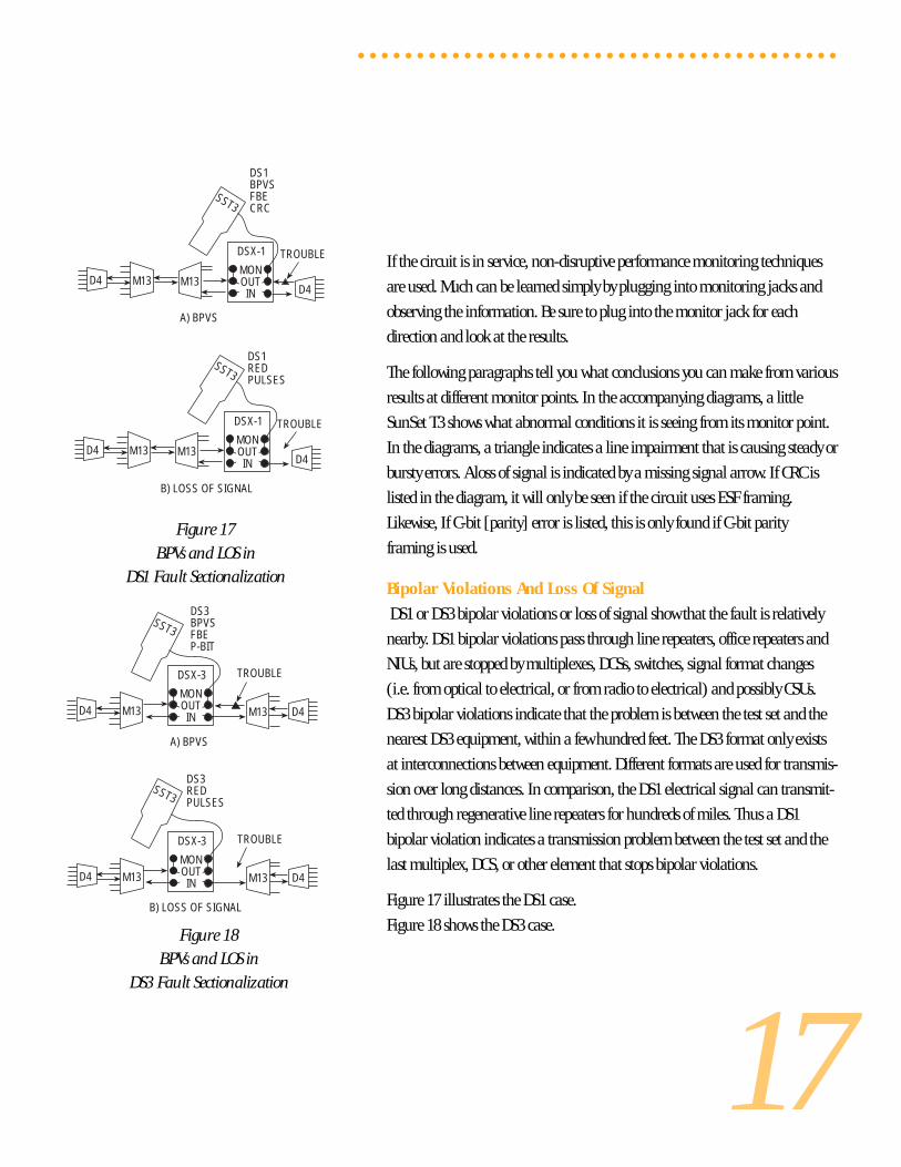
Figure 19
FBE and CRC in DS1 Testing
Figure 20FBE and C-bit in DS3 Testing
Frame Bit Errors, Bit Errors, CRC-6 Errors, C-Bit Parity Errors
These errors travel with the DS1 or DS3 circuit for the entire length of the
circuit. They pass through higher order multiplexes. They also pass through
changes in line format from copper to fiber, fiber to radio, etc. If these errors are
found with bipolar violations, then the problem is local. If these errors are
found without bipolar violations, then the problem is behind the last format
change. Figures 19 and 20 show what these errors mean when they are seen
○ ○ ○ ○ ○ ○ ○ ○ ○ ○ ○ ○ ○ ○ ○ ○ ○ ○ ○ ○ ○ ○ ○ ○ ○ ○ ○ ○ ○ ○ ○ ○ ○ ○ ○ ○ ○ ○ ○ ○ ○
TROUBLEHERE OR HERE
M13M13D4D4
SST3
MONOUT
IN
DSX-1
DS1FBECRC
A) TEST AT DSX-1
TROUBLE
M13M13D4MONOUT
IN
DSX-3
B) CHANNELIZED DS1 TEST AT DSX-3
D4
SST3DS1 FBEDS1 CRCDS3 OK
TROUBLE HERE OR HERE
DS1
DS3
M13 FIBERMUX
DS3FIBERMUX
3x1DCSMON
OUTIN
DSX-3
SST3 DS1 FBE, CRCDS3 FBE, P-BIT, C-BIT
19
○ ○ ○ ○ ○ ○ ○ ○ ○ ○ ○ ○ ○ ○ ○ ○ ○ ○ ○ ○ ○ ○ ○ ○ ○ ○ ○ ○ ○ ○ ○ ○ ○ ○ ○ ○ ○ ○ ○ ○ ○
without BPVs.
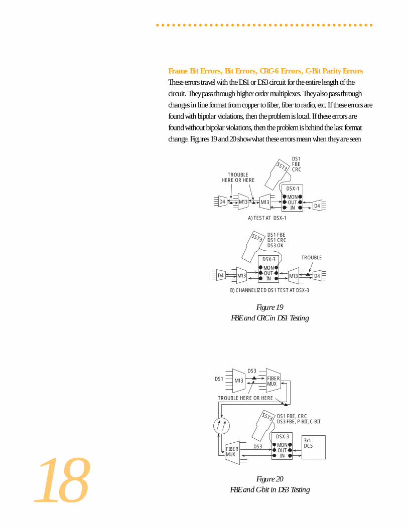
AIS And Yellow Alarm
AIS means that there is a problem on the line somewhere behind the
last multiplex, DCS, fiber mux, or other device that replaces a loss of signal
with AIS.
Yellow alarm means that the received signal has been lost at the end of the line
that generated the signal you are monitoring. When you monitor the other
direction, if the signal is framed, then the problem must exist between you and
the end of the line generating the yellow. If the signal is unframed (for example
AIS or loss of signal) the trouble is between you and the other end of the circuit.
Figure 21
DS1 Yellow and AIS
Figure 22DS3 Yellow and AIS
LOSS OF SIGNAL HERE
M13M13D4D4
SST3
MONOUTIN
DSX-1
DS1YELLOW
A) YELLOW ALARM AT DSX-1
AIS
YELLOW
LOSS OF SIGNALHERE
M13M13D4D4
SST3
MONOUTIN
DSX-1
DS1AIS
B) AIS AT DSX-1
AIS
LOSS OF SIGNAL HERE
DS1DS3
M13 FIBERMUX
DS3 AISFIBERMUX
3x1DCSMON
OUTIN
DSX-3
SST3DS1 FRAME LOSSDS3 AIS
CHANNELIZEDDS3 AIS
DS3 YEL
DS3 AIS
SST3DS1 OKDS3 YELLOW
20
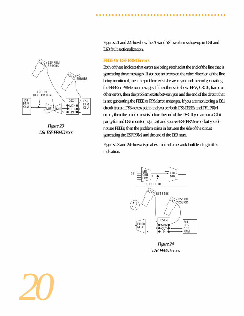
Figure 23DS1 ESF PRM Errors
Figure 24
DS3 FEBE Errors
○ ○ ○ ○ ○ ○ ○ ○ ○ ○ ○ ○ ○ ○ ○ ○ ○ ○ ○ ○ ○ ○ ○ ○ ○ ○ ○ ○ ○ ○ ○ ○ ○ ○ ○ ○ ○ ○ ○ ○ ○
Figures 21 and 22 show how the AIS and Yellow alarms show up in DS1 and
DS3 fault sectionalization.
FEBE Or ESF PRM Errors
Both of these indicate that errors are being received at the end of the line that is
generating these messages. If you see no errors on the other direction of the line
being monitored, then the problem exists between you and the end generating
the FEBE or PRM error messages. If the other side shows BPVs, CRC-6, frame or
other errors, then the problem exists between you and the end of the circuit that
is not generating the FEBE or PRM error messages. If you are monitoring a DS1
circuit from a DS3 access point and you see both DS3 FEBEs and DS1 PRM
errors, then the problem exists before the end of the DS3. If you are on a C-bit
parity framed DS3 monitoring a DS1 and you see ESF PRM errors but you do
not see FEBEs, then the problem exists in between the side of the circuit
generating the ESF PRMs and the end of the DS3 mux.
Figures 23 and 24 show a typical example of a network fault leading to this
indication.
TROUBLE HERE
DS1M13CBITFRM
FIBERMUX
FIBERMUX
3x1DCSCBITFRM
MONOUTIN
DSX-3
SST3 DS3 FEBE
SST3DS1 OKDS3 OK
TROUBLEHERE OR HERE
M13M13
SST3
MONOUTIN
DSX-1
ESF PRMERRORS
ESFPRMCSU
ESFPRMCSU
SST3 NOERRORS

22 Great Oaks BoulevardSan Jose, CA 95119
Telephone (408) 363-8000 Fax (408) 363-8313Email: [email protected] • Internet: http://www.sunrisetelecom.com