
Aerospace Systems Technical Group Presented by Carla Landsberg.
1
Working Group UpdateMANUFACTURING, INTEGRATED STRUCTURES, & COMMUNITY IMPACTTransformative Vertical Flight Workshop,Sept 29, 2016
Michael Patterson, PhD
Aerospace Engineer
NASA Langley Research Center
Electric propulsion and simplified vehicle ops. were identified early as “big hitter” technologies, but what else is required?
In Kansas City (Oct 2015) held “Other” breakout session• The community identified many different areas of interest
including airspace, acoustics, safety, public perception, manufacturing, materials, infrastructure, and more
• Airspace became standalone group
• Some areas/investments were integrated into the other working groups
• (Most of) the remaining investments fit into three categories:Manufacturing
Integrated Structures
Community Impact
Where did Manufacturing, Integrated Structures, & Community Impact come from?
2
3
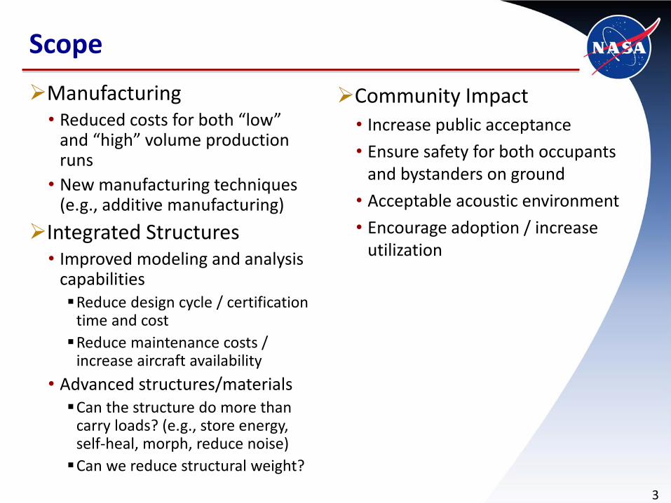
Manufacturing• Reduced costs for both “low”
and “high” volume production runs
• New manufacturing techniques (e.g., additive manufacturing)
Integrated Structures• Improved modeling and analysis
capabilitiesReduce design cycle / certification
time and cost
Reduce maintenance costs / increase aircraft availability
• Advanced structures/materialsCan the structure do more than
carry loads? (e.g., store energy, self-heal, morph, reduce noise)
Can we reduce structural weight?
Community Impact• Increase public acceptance
• Ensure safety for both occupants and bystanders on ground
• Acceptable acoustic environment
• Encourage adoption / increase utilization
Scope
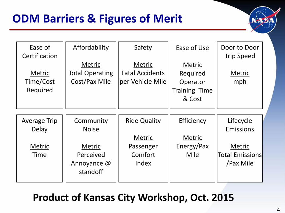
ODM Barriers & Figures of Merit
4
Affordability
MetricTotal Operating Cost/Pax Mile
Ease of Certification
MetricTime/Cost Required
Door to Door Trip Speed
Metricmph
Ease of Use
MetricRequired Operator
Training Time & Cost
Safety
MetricFatal Accidents
per Vehicle Mile
Community Noise
MetricPerceived
Annoyance @ standoff
Ride Quality
MetricPassengerComfort
Index
Efficiency
MetricEnergy/Pax
Mile
Average Trip Delay
MetricTime
LifecycleEmissions
MetricTotal Emissions
/Pax Mile
Product of Kansas City Workshop, Oct. 2015

ODM Barriers & Figures of Merit
5
Affordability
MetricTotal Operating Cost/Pax Mile
Ease of Certification
MetricTime/Cost Required
Door to Door Trip Speed
Metricmph
Ease of Use
MetricRequired Operator
Training Time & Cost
Safety
MetricFatal Accidents
per Vehicle Mile
Community Noise
MetricPerceived
Annoyance @ standoff
Ride Quality
MetricPassengerComfort
Index
Efficiency
MetricEnergy/Pax
Mile
Average Trip Delay
MetricTime
LifecycleEmissions
MetricTotal Emissions
/Pax Mile
Primary Secondary

6
COMMUNITY IMPACT:ACOUSTICS

Noise control technologies
Metrics: i.e., how to measure annoyance?
Modeling tools
Design for low noise
• Example: YO-3A“Silent” at altitudes of 800-1500 ft
Flew in Vietnam and never took a round
Used by NASA to measure rotorcraft noise in flight
Low prop tip speed
•New options with DEP
Acoustics Overview
7
-30
-25
-20
-15
-10
-5
0250 300 350 400 450 500 600 700 800 900 919
Effect of Propeller Tip Speed on Noise Level
(a 5th order function)
Propeller Tip Speed (ft/sec)
dB YO-3A
Tip Speed
SR-22
Tip Speed
nasa.gov
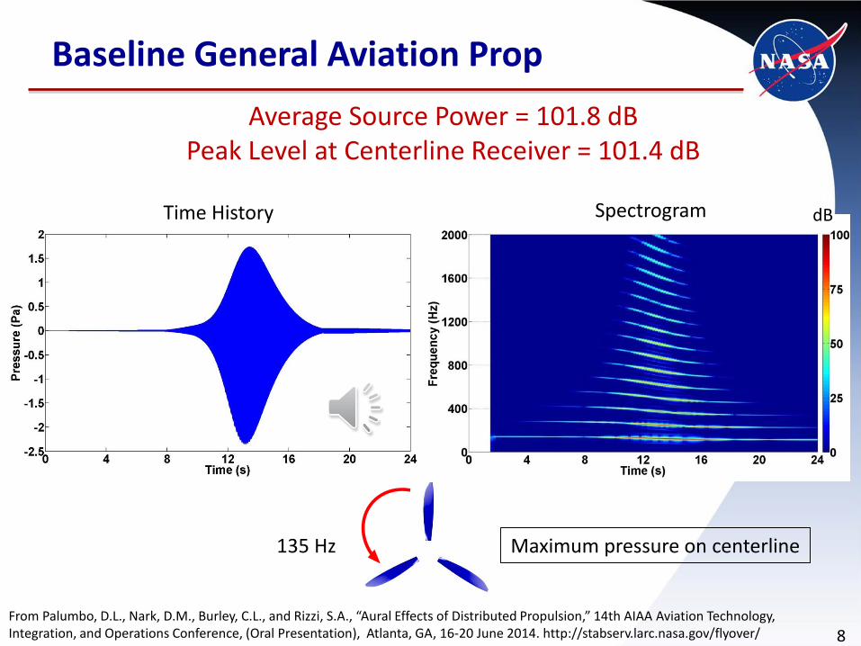
Baseline General Aviation Prop
8
Time History
Average Source Power = 101.8 dB Peak Level at Centerline Receiver = 101.4 dB
dB
135 Hz Maximum pressure on centerline
Spectrogram
From Palumbo, D.L., Nark, D.M., Burley, C.L., and Rizzi, S.A., “Aural Effects of Distributed Propulsion,” 14th AIAA Aviation Technology, Integration, and Operations Conference, (Oral Presentation), Atlanta, GA, 16-20 June 2014. http://stabserv.larc.nasa.gov/flyover/

9
18 LE Props all in phrase
Average Source Power = 89.0 dB (-12.8 dB re: GA Prop) Peak Level at Centerline Receiver = 96.4 dB (-5 dB re: GA Prop)
dB
All 293.3 Hz and in phase
Maximum pressure on centerline
Time History Spectrogram
From Palumbo, D.L., Nark, D.M., Burley, C.L., and Rizzi, S.A., “Aural Effects of Distributed Propulsion,” 14th AIAA Aviation Technology, Integration, and Operations Conference, (Oral Presentation), Atlanta, GA, 16-20 June 2014. http://stabserv.larc.nasa.gov/flyover/
10
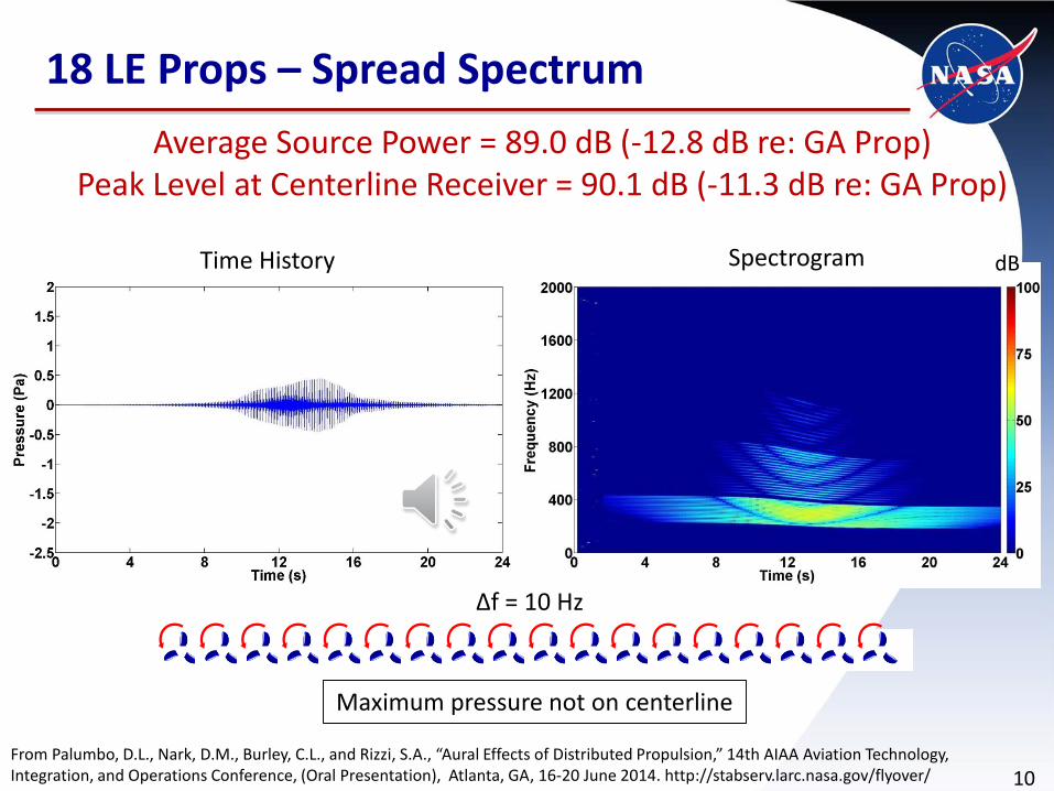
18 LE Props – Spread Spectrum
Time History Spectrogram
Average Source Power = 89.0 dB (-12.8 dB re: GA Prop) Peak Level at Centerline Receiver = 90.1 dB (-11.3 dB re: GA Prop)
dB
Δf = 10 Hz
Maximum pressure not on centerline
From Palumbo, D.L., Nark, D.M., Burley, C.L., and Rizzi, S.A., “Aural Effects of Distributed Propulsion,” 14th AIAA Aviation Technology, Integration, and Operations Conference, (Oral Presentation), Atlanta, GA, 16-20 June 2014. http://stabserv.larc.nasa.gov/flyover/

11
18 LE Props – Spread Spectrum
Time History Spectrogram
Average Source Power = 89.0 dB (-12.8 dB re: GA Prop) Peak Level at Centerline Receiver = 90.7 dB (-10.7 dB re: GA Prop)
dB
Δf = 0.5 Hz
Maximum pressure not on centerline
From Palumbo, D.L., Nark, D.M., Burley, C.L., and Rizzi, S.A., “Aural Effects of Distributed Propulsion,” 14th AIAA Aviation Technology, Integration, and Operations Conference, (Oral Presentation), Atlanta, GA, 16-20 June 2014. http://stabserv.larc.nasa.gov/flyover/
12
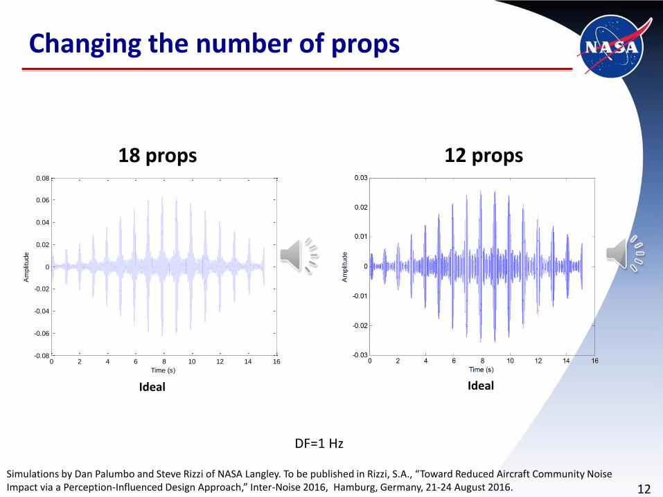
Changing the number of props
0 2 4 6 8 10 12 14 16-0.08
-0.06
-0.04
-0.02
0
0.02
0.04
0.06
0.08
Time (s)
Am
plit
ude
Ideal Ideal
18 props 12 props
DF=1 Hz
Simulations by Dan Palumbo and Steve Rizzi of NASA Langley. To be published in Rizzi, S.A., “Toward Reduced Aircraft Community Noise Impact via a Perception-Influenced Design Approach,” Inter-Noise 2016, Hamburg, Germany, 21-24 August 2016.
13
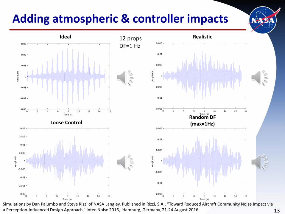
Adding atmospheric & controller impacts
0 2 4 6 8 10 12 14 16-0.03
-0.02
-0.01
0
0.01
0.02
0.03
Time (s)
Am
plit
ude
Ideal
0 2 4 6 8 10 12 14 16-0.015
-0.01
-0.005
0
0.005
0.01
0.015
Time (s)
Am
plit
ude
Realistic
0 2 4 6 8 10 12 14 16-0.02
-0.015
-0.01
-0.005
0
0.005
0.01
0.015
0.02
Time (s)
Am
plit
ude
Loose Control
0 2 4 6 8 10 12 14 16-0.015
-0.01
-0.005
0
0.005
0.01
0.015
Time (s)
Am
plit
ude
Random DF (max=1Hz)
12 propsDF=1 Hz
Simulations by Dan Palumbo and Steve Rizzi of NASA Langley. Published in Rizzi, S.A., “Toward Reduced Aircraft Community Noise Impact via a Perception-Influenced Design Approach,” Inter-Noise 2016, Hamburg, Germany, 21-24 August 2016.
14DF
Pe
ak
TN
R(d
B)
0 1 2 3 4 510
20
30
40
50
60
Ideal
Realistic
RandomDF
Loose Control
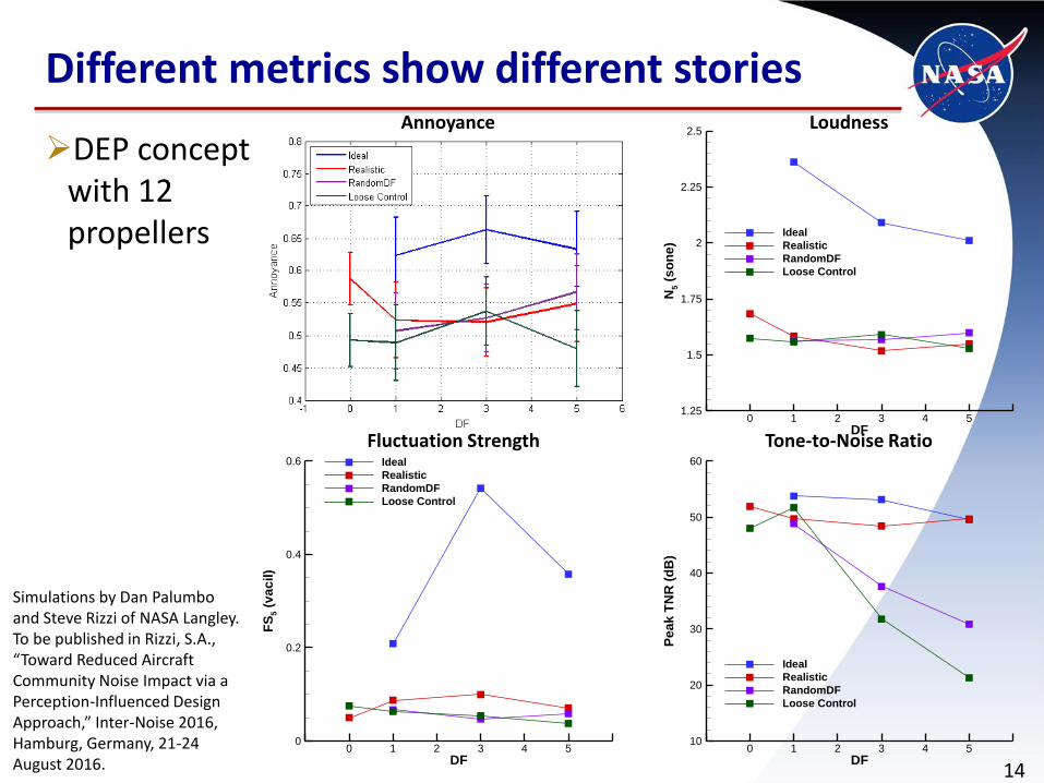
DEP concept with 12 propellers
Different metrics show different stories
DF
N5
(so
ne
)
0 1 2 3 4 51.25
1.5
1.75
2
2.25
2.5
Ideal
Realistic
RandomDF
Loose Control
DF
FS
5(v
ac
il)
0 1 2 3 4 50
0.2
0.4
0.6 Ideal
Realistic
RandomDF
Loose Control
Annoyance Loudness
Fluctuation Strength Tone-to-Noise Ratio
Simulations by Dan Palumbo and Steve Rizzi of NASA Langley. To be published in Rizzi, S.A., “Toward Reduced Aircraft Community Noise Impact via a Perception-Influenced Design Approach,” Inter-Noise 2016, Hamburg, Germany, 21-24 August 2016.
15
COMMUNITY IMPACT:SAFETY CONSIDERATIONS
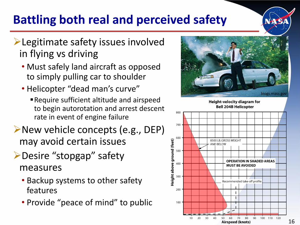
Legitimate safety issues involved in flying vs driving• Must safely land aircraft as opposed
to simply pulling car to shoulder
• Helicopter “dead man’s curve”Require sufficient altitude and airspeed
to begin autorotation and arrest descent rate in event of engine failure
New vehicle concepts (e.g., DEP) may avoid certain issues
Desire “stopgap” safety measures• Backup systems to other safety
features
• Provide “peace of mind” to public
Battling both real and perceived safety
16
blogs.mass.gov
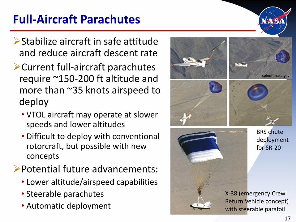
Stabilize aircraft in safe attitude and reduce aircraft descent rate
Current full-aircraft parachutes require ~150-200 ft altitude and more than ~35 knots airspeed to deploy• VTOL aircraft may operate at slower
speeds and lower altitudes
• Difficult to deploy with conventional rotorcraft, but possible with new concepts
Potential future advancements:• Lower altitude/airspeed capabilities
• Steerable parachutes
• Automatic deployment
Full-Aircraft Parachutes
17
spinoff.nasa.gov
X-38 (emergency Crew Return Vehicle concept) with steerable parafoil
BRS chute deployment for SR-20

Absorb kinetic energy in materials as opposed to transferring to occupants
Developed to date for spacecraft and military aircraft
Example systems:•Deployable energy
absorbing concept
• Full aircraft airbagsDouble as floatation devices
in case of water landing
Energy absorbing systems
18Videos of Deployable Energy Absorbing (DEA) concept from Dr. Sotiris Kellas of NASA Langley

Ballistic recovery system (BRS) for > ~50 ft altitude and ~30 knots
Energy absorbing systems (EAS) for < ~50 ft and ~30 knots
Eliminating the “dead man’s curve”
19
Calculations from Fredericks, Bill. “Impact of Operational Requirements on Intra-Urban VTOL Conceptual Design.” AIAA Aviation. June 2016. Oral Presentation. Also see AIAA 2016-3466
0
20
40
60
80
100
120
0 20 40 60 80 100
He
igh
t A
GL
(Ft)
Airspeed (kts)
BRS
EASOperations Must be Avoided

20
MANUFACTURING

Additive Manufacturing (AM)
21
Potential for• Reduced weight (i.e., higher
efficiency, more range/payload)
• Reduced cost (less tooling; low-volume production can reutilize same machines)
AM handbook
New AM methods
AM of • sub-systems (e.g., electric
motors, fuel cells)
• primary structure
• entire aircraft
rita.dot.gov
“Guide for Low CostDesign andManufacturingof CompositeGeneral AviationAircraft”

Idea: reduce manual labor required (i.e., recurring cost)
Robotic stations can be programed to do many tasks
• Swapping ‘end effectors’
Enables scalable manufacturing
• Small production runs could employ a small number of robotic stations, each serving multiple functions
• Large production runs could employ many robotic stations, each serving a small number of functions
BMW i3 assembly line
Flexible Robotic Manufacturing
22
nasa.gov
sec.gov

23
INTEGRATED STRUCTURES

Digital twin•Use models to predict
performance and failures in physical aircraft prior to flight
Digital Twin / Smart Hangar
24
SAW Interrogator
IVHM System
SAW Sensor
Fiber Optic Strain
Sensors
Fiber Optic Ultrasonic Sensors
Laser Vibrometer/Thermography/RF/etc.
Piezoelectric Patch
Digital Twin
NDE
Instrumentation
Digital twin POC Paul Leser (NASA Langley); Smart Hangar POC and figure credit: Cy Wilson (NASA Langley)
Smart hangar
• Assess vehicle health while in the hangar with on- and off-board sensors
Potential benefits
• Increase safety Frequent inspection
Help make “no go” decisions
• Reduce costsEnable condition-
based maintenance
ID problems early

Many small aircraft cannot afford weight penalty and cost of current de-icing systems
Coatings based on nano-materials well-matched to lower-than-transonic speeds (i.e., won’t wear away)
Ideally paired with electric propulsion’s ability to run at higher powers for short periods of time to climb through potential icing conditions
Can increase utilization
Anti-ice coatings
25POCs Joe Smith (NASA Langley) and Chris Wohl (NASA Langley)
faa.gov
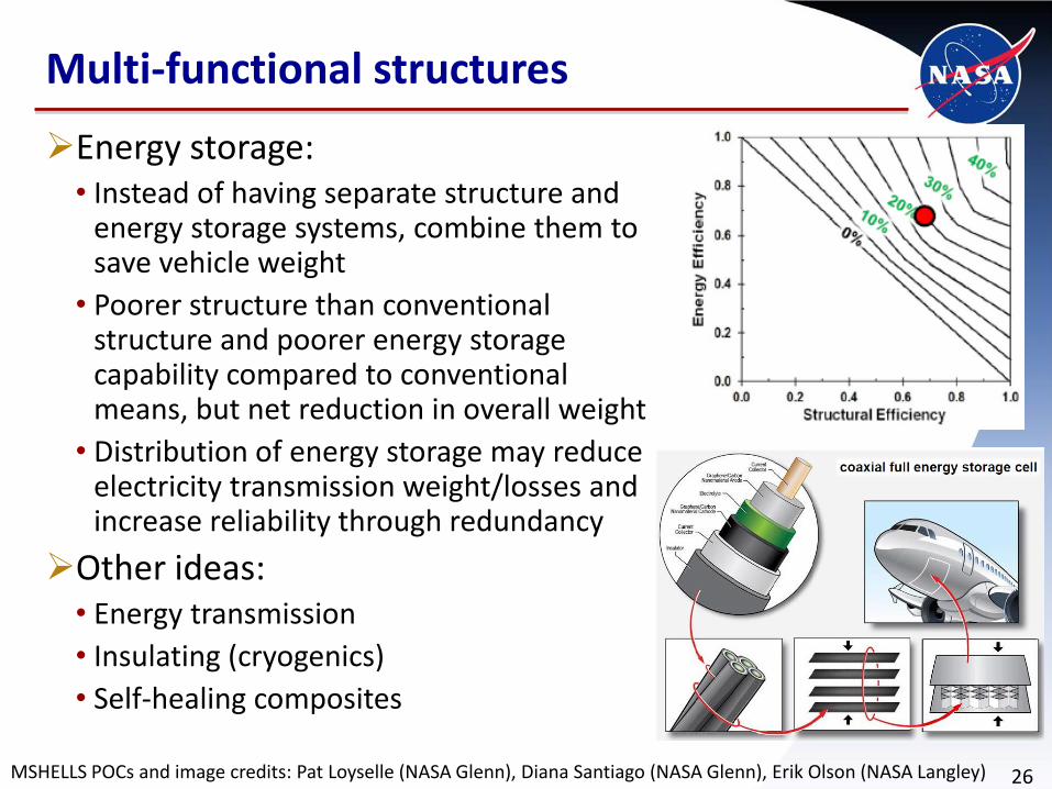
Energy storage:• Instead of having separate structure and
energy storage systems, combine them to save vehicle weight
• Poorer structure than conventional structure and poorer energy storage capability compared to conventional means, but net reduction in overall weight
• Distribution of energy storage may reduce electricity transmission weight/losses and increase reliability through redundancy
Other ideas:• Energy transmission
• Insulating (cryogenics)
• Self-healing composites
Multi-functional structures
26MSHELLS POCs and image credits: Pat Loyselle (NASA Glenn), Diana Santiago (NASA Glenn), Erik Olson (NASA Langley)

27
WRAP-UP

28Digital Twin
M-SHELLS(multi-functional
structures)
Roadmap: Manufacturing, Integrated Structures, & Community Impact
2016 2021 2026
Proof of Feasibility, Concept Exploration, Certification
Requirements, Basis
Design, Development, Certification, Validation of Operational
Prototypes
Early Operations, Maturation, Redesign,
Extension, and Technology Scaling
Inte
grat
ed
Stru
ctu
res
& M
ater
ials
Man
ufa
c-tu
rin
gC
om
mu
nit
y Im
pac
t
Extremely low altitude / speed full-aircraft parachute
High weight / advanced aircraft recovery parachute
Crashworthy structural design with energy-absorbing materials
Additive manufacturing (AM) ‘handbook’
Noise/annoyance metric development
Anti-ice coatings
Energy absorbing systems / external airbags
Flexible robotic manufacturing
AM of subsystems
Advanced additive (AM) manufacturing techniques
Noise control technologies
Progressive damage anal. methods for composites
Noise modeling tools with validation data sets
Structural health monitoring techs
Damage tolerant/self-healing composites
Smart Hangar
Morphing structures
X-57 VTOL X-Plane
Thin-Haul X-Plane
Scale-Up Tech Integration
Initial Operational Vehicles
Scale-Down Tech Integration
Leve
ragi
ng
Exis
tin
g In
vest
men
ts

Many potential technologies
Impact nearly every ODM goal
Main goals of investments:
• Increase safety
• Reduce community noise/annoyance
• Reduce structural weight
• Reduce acquisition costs
Acoustics and safety technologies likely required
• Public must accept these vehicles (both to fly in them and to allow them to fly over)
•Other individual technologies likely not absolutely necessary but some combination of them may be
Summary
29

30
QUESTIONS?

31
BACKUPS

32
MISC Contributions to ODM Goals
• Potential to reduce certification requirements for other technologies with improved “stopgap” safety systems
• Improved modeling may reduce need for extensive physical testing
• “Handbooks” to help enable certification of new manufacturing processes

• Improved “stopgap” safety systems to complement other technologies (e.g., SVO-related technologies)
• Reduced risk of flying with unsound structure• Structural health monitoring/modeling• Improved material damage tolerance
MISC Contributions to ODM Goals
33
34
• Reduced system weights can lead to reduced acquisition costs
• Improved modeling and monitoring of structures can reduce costs• Acquisition costs (i.e., design,
certification)• Operating costs (i.e., reduced
maintenance)
• Improved safety and reduced damage in crashes reduces depreciation costs
MISC Contributions to ODM Goals
35
• Only minor impacts • Safety technologies could reduce required
pilot certification requirements (e.g., less off-nominal training required)
• Structural monitoring/modeling reduces required operator knowledge/time for inspections
MISC Contributions to ODM Goals
• Potential for more direct routes / desirable altitudes• Anti-ice coatings to fly through instead of
around known icing conditions• Improved safety systems (i.e., parachutes,
airbags) to reduce concerns of low flight over populated areas
• Multi-mode vehicles • Reduced mode change time• May be enabled with morphing
structures
MISC Contributions to ODM Goals
36
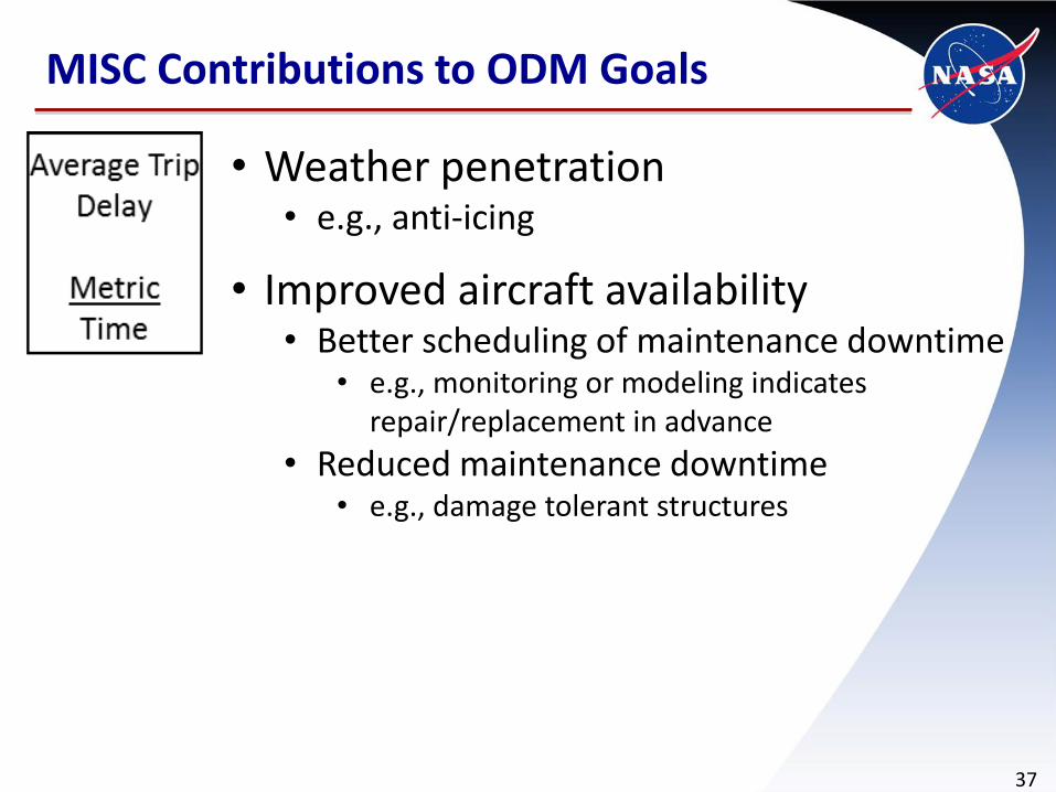
• Weather penetration• e.g., anti-icing
• Improved aircraft availability• Better scheduling of maintenance downtime
• e.g., monitoring or modeling indicates repair/replacement in advance
• Reduced maintenance downtime• e.g., damage tolerant structures
MISC Contributions to ODM Goals
37
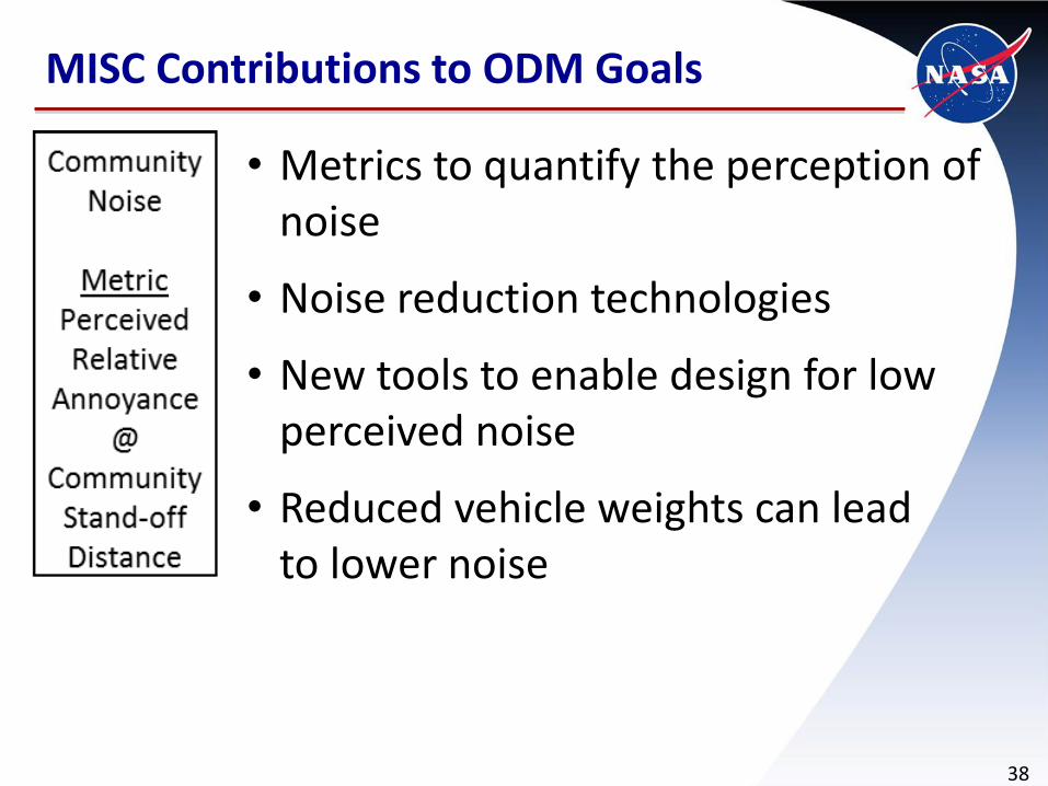
• Metrics to quantify the perception of noise
• Noise reduction technologies
• New tools to enable design for low perceived noise
• Reduced vehicle weights can lead to lower noise
MISC Contributions to ODM Goals
38

• Decreased cabin noise
• Indirect impacts possible through • morphing structures• improved actuators that may help
enable gust load alleviation systems
MISC Contributions to ODM Goals
39
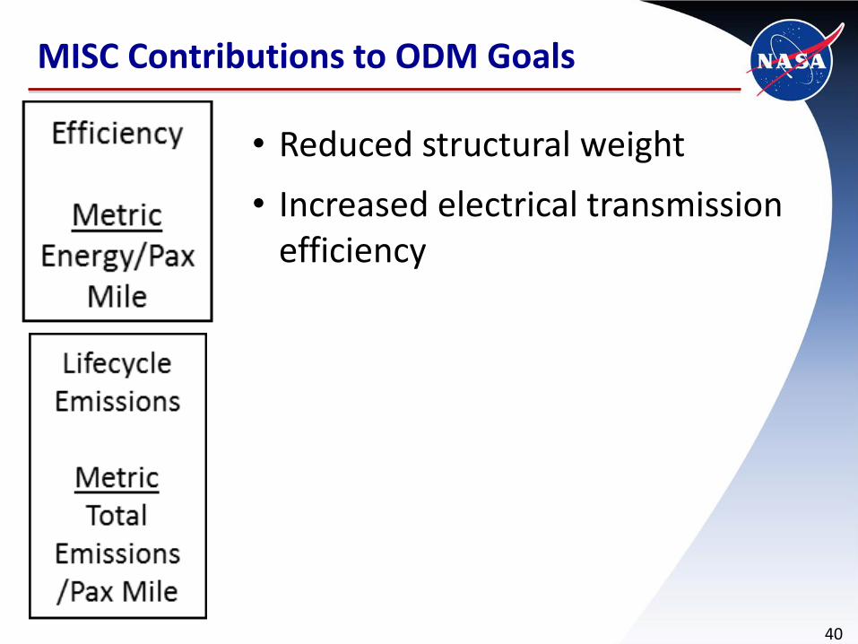
• Reduced structural weight
• Increased electrical transmission efficiency
MISC Contributions to ODM Goals
40

Manufacturing• Flexible robotic manufacturingReplace many manual labor tasks with robotic stations
Robotic stations can be programed to do many different tasks
Small production runs could employ a small number of robotic stations, each serving multiple functions
Large production runs could employ many robotic stations, each serving a small number of functions
• Additive manufacturing handbookDefine “best practices” for design and inspection
Determine sufficient factors of safety for different processes
• Additive manufacturing of subsystems (e.g., fuel cells, electric motors)
•New additive manufacturing methods (e.g., liquidjetprinting, robotic direct fiber placement)
Investment List: Example Subset
41

Integrated Structures• Multi-functional structures with energy storage (e.g., M-SHELLS)Instead of having separate structure and energy storage systems, combine
them to save vehicle weightPoorer structure than conventional structure and poorer energy storage
capability compared to conventional means, but net reduction in overall weightDistribution of energy storage may reduce electricity transmission
weight/losses and increase reliability through redundancy
• Improved modeling of composite structuresDevelop improved, high-fidelity progressive damage analysis methods for
composite materials to predict onset and propagation of damageUtilize tools to develop more structurally efficient designs and/or reduce
design/certification time with less physical testing than currently required
• Morphing structures / advanced actuatorsChange vehicle characteristics (e.g., wing camber) throughout mission to be
more advantageous for different phases of flightMay help enable multi-mode vehicles that can safely fly and drive on roads
• Damage-tolerant / “self-healing” compositesDamage from accidental damage (e.g., dropping tools), high voltage electrical
shortages, projectiles, etc. can be automatically mitigated
Investment List: Example Subset
42

Community Impact: Safety enhancements• Extremely low altitude aircraft parachuteAircraft parachutes serve as safety backup in case of off-nominal situation,
decreasing aircraft acceleration to safe levels prior to ground impact
Current aircraft parachutes require altitude/airspeed to successfully deploy and are not applicable to VTOL aircraft operating close to people at low altitudes
Low altitude parachute systems can eliminate “coffin corner”/“dead man’s curve” for VTOL operations and reduce risk of damage to objects on ground
• External aircraft airbagProvides absorption of energy during crash while reducing structural
deformation to enable safe egress post-crash
Reduction in damage to objects on ground upon landing
Can be utilized as a “life jacket” to keep aircraft afloat in water, reducing chances of drowning if aircraft crashes over water
• Energy absorbing compositesCrash loads are absorbed by the structure while enabling safe egress post-crash
Investment List: Example Subset
43
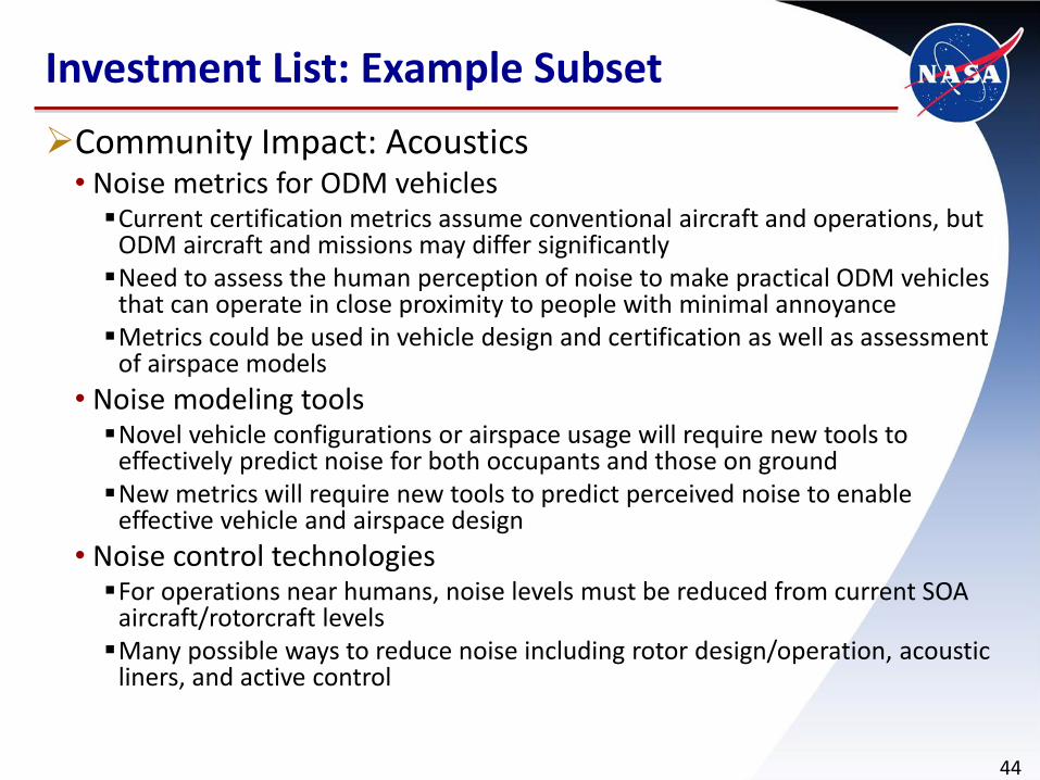
Community Impact: Acoustics• Noise metrics for ODM vehiclesCurrent certification metrics assume conventional aircraft and operations, but
ODM aircraft and missions may differ significantlyNeed to assess the human perception of noise to make practical ODM vehicles
that can operate in close proximity to people with minimal annoyanceMetrics could be used in vehicle design and certification as well as assessment
of airspace models
• Noise modeling toolsNovel vehicle configurations or airspace usage will require new tools to
effectively predict noise for both occupants and those on groundNew metrics will require new tools to predict perceived noise to enable
effective vehicle and airspace design
• Noise control technologiesFor operations near humans, noise levels must be reduced from current SOA
aircraft/rotorcraft levelsMany possible ways to reduce noise including rotor design/operation, acoustic
liners, and active control
Investment List: Example Subset
44

Community Impact: increased utilization• Anti-ice coatings based on nano-materialsSmall aircraft (particularly those with low utilization) cannot afford weight
penalty, cost of current de-icing systems
Coatings well-matched to lower-than-transonic speeds (i.e., won’t wear away)
Ideally paired with electric propulsion’s ability to run at higher powers for short periods of time to climb through potential icing conditions
• Digital twinMulti-physics, probabilistic simulation of aircraft used to predict performance
and failures in physical aircraft prior to flight
Predictions can be used to make “no go” decisions, enable condition-based maintenance, and inform risk management
• Smart hangarCouple onboard sensors and external non-destructive evaluation techniques
to assess vehicle health while in the hangar
Provides frequent, automatic inspections to identify problems early when repairs may be less costly and reduce manual inspection time
Investment List: Example Subset
45

Manufacturing
• Flexible robotic manufacturing
• Additive manufacturing handbook
•New additive manufacturing methods (e.g., liquidjet printing, robotic direct fiber placement)
• Additive manufacturing of subsystems (e.g., fuel cells, electric motors)
Investment List (1 of 3)
46

Integrated Structures
•Multi-functional structures with energy storage
• Improved modeling of composite structures
•Damage-tolerant / “self-healing” materials
•Morphing structures / advanced actuators
• Polyimide aerogels for primary wing structures
•Multi-functional structures with cryogenically cooled electricity transmission
•Modular structures and design methods for these structures
•New nano-structure materials or other “superstructures” with improved material properties
Investment List (2 of 3)
47

Community Impact• Safety enhancementsExtremely low altitude aircraft parachute
External aircraft airbag for improved survivability and flotation
Crashworthy structural design using energy absorbing composites
Advanced aircraft recovery parachute technologies (e.g., steerable parachutes, autonomous activation, extractor motor control, etc)
• AcousticsNoise metrics for ODM vehicles (to determine perceived noise)
Noise modeling tools
Noise control technologies (e.g., liners, active control)
• Increased utilizationAnti-ice coatings
Digital twin
Smart hangar
Investment List (3 of 3)
48


