Working Group COFREND « Eddy Current NDT modeling »: … · 2014-10-23 · 1 / 15 Working Group...
16
1 / 15 Working Group COFREND « Eddy Current NDT modeling »: Benchmarks for validating and improving simulation codes acceptation Fabrice FOUCHER 1 , Léa MAURICE 2 , Thierry SOLLIER 3 , Christophe REBOUD 4 , François DENEUVILLE 5 , Adrien TRILLON 5 , Pierre THOMAS 6 1 EXTENDE, 15 Avenue Emile BAUDOT, 91300 Massy, France 2 EDF/CEIDRE, 2 rue Ampère, 93206 Saint Denis, FRANCE 3 Institut de Radioprotection et de Sûreté Nucléaire, 92262 Fontenay, FRANCE 4 CEA LIST, Saclay, 91191 Gif sur Yvette, FRANCE 5 VALLOUREC, Centre de recherche, 60 Route de Leval - BP20149, 59620 Aulnoye-Aymeries, FRANCE 6 EDF R&D, 1, avenue du Général de Gaulle, 92141 Clamart, FRANCE Abstract The working group « Eddy Current NDT modeling », hosted by the French NDT society “COFREND”, aims at proposing benchmark cases with associated experimental results, in order to support the validation and the acceptance of simulation programs, to put closer modeling tools and industrial needs, and finally to allow the NDT community to regularly exchange on the subjects related to Eddy Current simulation. Various types of members have joined the group and regularly participate to the task force: industrial users of NDT, services & engineering companies, universities and research centers. Several sectors are represented (power industry, aerospace, steel industry, etc.). This paper presents the latest works of the group performed within the last year. More precisely, two benchmarks have been addressed, inspired by inspection issues from the nuclear sector and the steel industry. Furthermore, new benchmarks are being proposed in order to be solved by candidate programs. Keywords: Simulation, Eddy Current Testing, Benchmark, French Society of NDT “COFREND” 1. Numerical modeling of NDE process 1.1 Simulation of Eddy Current Testing Nowadays, Non Destructive Tests (NDT) are widely used in many industries in order to control the integrity of materials. Modeling tools can bring a significant help at different stages of NDT operations: Design of the test process and the inspection procedure Performance demonstration Help for understanding and expertise of real inspection results Training It can also support Probability of Detection (PoD) campaigns based on uncertainties propagation [1], by reducing the number of physical tests on mock-ups, or by helping defects identification and sizing with inversion methods applied on measured signals. [2] Numerous papers highlight recent works where simulation played a major role for different industries: aerospace [3], steel industry [4], nuclear power generation, in France [5] or worldwide [6]. For instance, the European Network for Inspection and Qualification (ENIQ) promotes the use simulations (with recommended practice) in the framework of the qualification of a NDT process. [9]
Transcript of Working Group COFREND « Eddy Current NDT modeling »: … · 2014-10-23 · 1 / 15 Working Group...
1 / 15
Working Group COFREND « Eddy Current NDT modeling »:
Benchmarks for validating and improving simulation codes acceptation
Fabrice FOUCHER1, Léa MAURICE2, Thierry SOLLIER3, Christophe REBOUD4, François
DENEUVILLE5, Adrien TRILLON5, Pierre THOMAS6 1 EXTENDE, 15 Avenue Emile BAUDOT, 91300 Massy, France
2 EDF/CEIDRE, 2 rue Ampère, 93206 Saint Denis, FRANCE 3 Institut de Radioprotection et de Sûreté Nucléaire, 92262 Fontenay, FRANCE
4 CEA LIST, Saclay, 91191 Gif sur Yvette, FRANCE 5 VALLOUREC, Centre de recherche, 60 Route de Leval - BP20149, 59620 Aulnoye-Aymeries,
FRANCE 6 EDF R&D, 1, avenue du Général de Gaulle, 92141 Clamart, FRANCE
Abstract
The working group « Eddy Current NDT modeling », hosted by the French NDT society “COFREND”, aims at
proposing benchmark cases with associated experimental results, in order to support the validation and the
acceptance of simulation programs, to put closer modeling tools and industrial needs, and finally to allow the
NDT community to regularly exchange on the subjects related to Eddy Current simulation. Various types of
members have joined the group and regularly participate to the task force: industrial users of NDT, services &
engineering companies, universities and research centers. Several sectors are represented (power industry,
aerospace, steel industry, etc.). This paper presents the latest works of the group performed within the last year.
More precisely, two benchmarks have been addressed, inspired by inspection issues from the nuclear sector and
the steel industry. Furthermore, new benchmarks are being proposed in order to be solved by candidate
programs. Keywords: Simulation, Eddy Current Testing, Benchmark, French Society of NDT “COFREND”
1. Numerical modeling of NDE process
1.1 Simulation of Eddy Current Testing
Nowadays, Non Destructive Tests (NDT) are widely used in many industries in order to
control the integrity of materials. Modeling tools can bring a significant help at different
stages of NDT operations:
Design of the test process and the inspection procedure
Performance demonstration
Help for understanding and expertise of real inspection results
Training
It can also support Probability of Detection (PoD) campaigns based on uncertainties
propagation [1], by reducing the number of physical tests on mock-ups, or by helping defects
identification and sizing with inversion methods applied on measured signals. [2]
Numerous papers highlight recent works where simulation played a major role for different
industries: aerospace [3], steel industry [4], nuclear power generation, in France [5] or
worldwide [6]. For instance, the European Network for Inspection and Qualification (ENIQ)
promotes the use simulations (with recommended practice) in the framework of the
qualification of a NDT process. [9]
2 / 15
For Eddy Current Testing simulation, various tools exist based on different models (i.e.
different ways to adapt and solve Maxwell equations for Eddy Current configurations). A
typical Eddy Current test is an AC problem where Maxwell Equations can be reduced to a
single harmonic diffusion equation, provided that quasi-static hypothesis can be applied
(which is the case in NDT). But, if pulsed Eddy Current is considered, the same hypotheses
cannot be applied and a transient model is required.
1.2 Numerical methods
To solve these equations, a first approach consists in directly discretizing the study domain
and solves locally the Maxwell equations with a very restricted introduction of analytical
formulae or physical hypotheses such as the Finite Element method (FEM). It is largely used
for a wide range of physical problems for which it is quite well suited (mathematically
efficient as the equation system can be solved relying on a constant energy level).
Several software or codes dedicated to the solving of electromagnetic problems using Finite
Elements can be quoted such as:
- Code_Carmel3D (current version 2.4), co-developed by EDF R&D and L2EP
(Laboratoire d'Electrotechnique et d'Electronique de Puissance de Lille) in a mutual
laboratory called LAMEL.
- Flux3D (current version 11.2),software developed and distributed by CEDRAT
company,
- Opera (current version 16), software belonging to the software suite Vector Fields
Software, edited by Cobham company.
- ANSYS-Maxwell (current version 15.0), software developed and distributed by
ANSYS company.
- Comsol-Multiphysics (current version 4.3), multiphysics software including a low
frequency electromagnetic module, developed and distributed by the eponymous
company.
Finite Volume method is another approach based on the geometrical discretization of the
study domain. IREENA (Institut de Recherche en Energie Electrique de Nantes-Atlantique),
belonging to Nantes university, develops this type of models [7].
CIVA platform, fully dedicated to the simulation of NDT, developed by CEA DISC and
distributed by EXTENDE, also proposes a numerical model based on the Finite Integration
Technique to solve some configurations, as a part of its Eddy Current module.
1.3 Semi-analytical Methods
Another approach is to rely more on analytical formulae. Semi-analytical methods allow, by
doing some hypotheses on the geometrical or physical properties of the test configuration, and
by using adapted and/or original mathematical tools, to obtain precise results with very
interesting calculation times. Moreover, these tools are generally easier to use even if the
starting hypotheses generally lead to a more limited validity domain compared to fully
numerical models.
Most of the models implemented in the Eddy Current module of the CIVA platform rely on
such semi-analytical approach where only the flaw is discretized and implies numerical
operations (Volume Integral Method or Boundary Element Method solved using Green dyads
operators applied to the test configuration).

3 / 15
1.4 Metamodels for intensive simulation
Several applications, such as inversion procedures or POD studies, require a very large
amount of single results from different individual NDT configurations, to produce the final
result. In such situations, it is sometimes necessary to drastically reduce computation times.
To meet this requirement, a possible strategy consists in replacing the direct modelling by an
approximation based on the knowledge and the extrapolation of the model (only precise in a
given variation domain of input data). This « model of the model » called metamodel (also
called surface response) can be evaluated very quickly [1,1b].
1.5 Validation of simulation Tools
Each method has advantages and disadvantages, and to develop a model needs a lot of skills
different from the ones required in NDT. As a consequence, prior to use simulation tools, it is
necessary to know the validity domain of the code or to perform additional validation tests to
ensure its applicability for a given NDT application. The most convincing validation process
is to compare simulation results with experimental measurements. Another interesting way is
to compare several models together. It is even more interesting when these models are not
based on the same method as it allows to evaluate the hypotheses associated to each one (for
instance the accounting of boundary conditions at the infinite which distinguish finite element
models and semi-analytical/integral approach).
These two types of validation are recommended by the ENIQ. [9]
2. Working Group COFREND « Eddy Current Testing Modeling »
2.1 Description & Goals
Test cases or "benchmarks" on electromagnetic problems appeared in the 80s’. These
benchmarks were generally initiated by code developers, often coming from the academic
world. The « Testing Electromagnetic Analysis Method » (TEAM) workshops, developed in
the frame of COMPUMAG, have been extended to realist cases including NDT from 1987
[10]. The famous problems 8 and 15 from TEAM Workshops still remain today reference
cases for any electromagnetic codes wishing to tackle NDT problems. Other benchmarks
more specific to NDT arose in the 90s, such as the ACES Workshops, those proposed by the
World Federation of NDE Center in the US, or the JSAEM benchmarks in Japan [11].
But the definition of these benchmarks remained the initiative of academic world and the
tested configurations were not fully relevant with respect to nuclear or aerospace typical Eddy
Current inspection configurations. As a consequence, it has become necessary for industrials
to define test cases closer to their needs as soon as they started to really use such simulation
tools. Indeed, the use of a validated code on pure academic benchmarks is often not enough to
prevent this code from facing specific problems that can occur on realist industrial cases [12].
The working group « Simulation of Eddy Current NDT», hosted by the French society of
NDT “COFREND” (www.cofrend.com), was born from the statement of a lack of
representative validation cases from the industrial world.
Members of this group belong to various fields of activity:
- Industrial end users: VALLOUREC, EDF, AREVA, SNECMA, DASSAULT
AVIATION, AIRBUS GROUP,
- Government funded Institute : IRSN
4 / 15
- Academics and Research centers : CEA, Supélec/CNRS (L2S, LGEP),
IREENA
- Engineering & consulting companies : EXTENDE
- NDT equipment suppliers : ALPHATEST SYSTEMES
The group was born in 2004, and has regularly organized some meetings from 2005 (about 2
meetings a year with 8 to 15 participants).
The goals that the members have defined are the following:
To propose test cases with a unified way of describing them (see next part),
To Promote and give access to the benchmark results: The working group wishes
the COFREND website to hold as soon as possible these test cases,
To ease the solving of test cases and the exchange of know-how,
To inform the NDT community about the possibilities of modeling Eddy Current
problems: to highlight the capabilities of the simulation should help to increase the
understanding and the acceptation of modeling in industrial NDT processes.
2.2 Definition & description of industrial test cases
As said above, the benchmarks should be close to real industrial configurations. However, all
input parameters and output data should be clear and available for everybody, to allow the
solving of this benchmark by different people in similar conditions. Therefore, it cannot be
subject to confidentiality issues.
The characteristics of a good benchmark are given below:
Realist: The benchmark should be representative of a generic industrial configuration,
Simple: It can be easily described and modeled by a large number of codes,
Original: It does not « repeat » an existing benchmark,
Verifiable: All necessary input data are known and can be published: geometry &
material of the work piece, sensor parameters, acquisition data (scanning, frequency,
and acquisition channels). It has reference results given from experimental
measurements or from other simulated data, acknowledged as a reference solution,
which is the basis for a comparison of the results given by the candidate codes.
This exhaustive description of a benchmark is the first task to do….and this is often the more
difficult part! Sometimes, it faces problems of confidentiality for ET sensor parameters.
Sometimes, it is difficult to know the exact parameters of the part material (especially for
ferromagnetic part) and sometimes, the difficulty is also to realize experimental trials or to get
experimental data from industrial acquisitions that can be disclosed publicly.
A generic model for the description of a test case has been defined by the group in 2010.
2.3 Benchmarks of the COFREND Working group
This part describes the benchmarks proposed by the WG. Some of them have been solved
already by one or several simulation codes while other ones are only at the description stage.
This list is not closed and should evolve in the future.
Benchmark #2: Through wall/ Internal/ External notches in thin non magnetic & conductive
slabs (proposed by EdF-CEA). The industrial origin of this case is the inspection of steam
generator tubes in Inconel by rotating probes in nuclear power plants (even if this case has
been described in a planar configuration). In particular, it was motivated by the difficulty to
solve configurations with through wall flaws [12]. Two types of sensors are proposed: A
common function one with a single probe, a separated function one (or “reflection mode”)
with 2 coils, operating absolute measurement

5 / 15
Benchmark #6: Encircling coils on a stainless steel tube with Flat Bottom Holes (FBH)
(proposed by Vallourec). This benchmark addresses the topic of industrial tube inspection at
the manufacturing stage on production lines, representative of steel industry issues.
Benchmark #7: Very small flaws on plates (by SNECMA & CEA). This benchmark is
currently at the description stage and will address the problem of very small flaw (size less
than 1mm x 1mm x 1mm) inspected with ferrite-core sensors.
Benchmark #8: Remote Field Testing (proposed by CEA). This case has been published by
CEA at ENDE 2007 [23]. It involves a notch, FBHs and external grooves in a ferromagnetic
tubes (conductivity of 6.25 MS/m and a relative permeability evaluated at 210), inspected
with the Remote Field Eddy Current technique (RFT).
Benchmark #9: Multi-layer fastened plate (proposed par CEA). This test case comes from
aeronautics configurations by considering a bilayer structure separated by a thin air gap and
fastened with a rivet. It includes a notch of 0.234mm initiated from the rivet hole,
representative of typical cracking phenomena nearby bore areas. The sensor used is a simple
coil operating at common function, at 1 & 5 kHz. First results on these cases have already
been obtained with CIVA 11.0 and presented at the conference QNDE 2013 [24].
Benchmark #10: Multilayers slabs with varying electromagnetic properties (proposed by
IRSN, EDF & VALLOUREC). This case is currently in the description stage.
3. Software Performance for Eddy Current Simulation
Computation codes capabilities can be expressed through different criteria:
Versatility: Extent of configuration types that can be simulated,
Accuracy of results,
Computation times,
Graphical User Interface proposed: Easy or not easy to use and requiring few or strong
numerical expertise to obtain a good result.
The constant improvement of processors performance allows decreasing computation times
while the size of discretization and the versatility of the possibilities increase.
3.1 Finite Element computation improvements
For FEM tools, the volume of discretization for a given NDT configuration, in terms of
number of nodes for instance, illustrates the capacity to represent more accurately and with
more details the real configurations (e.g. complex geometries) while solving them with a good
accuracy. Therefore, this is interesting to notice the evolution of this parameter.
In order to illustrate this, a brief comparison study is performed between 1996 to nowadays,
on the basis of the solving of the Team Workshop 8 benchmark. In 1996 [10], Turner
mentioned that one of the challenge for the solving of numerical electromagnetic problems
was to solve realistic models on a PC. In these days, the TEAM Problem #8 has been solved
with the software OPERA on a Pentium PC with a very coarse mesh of 8607 nodes.
Computation times were 10 minutes per position, leading to 5 hours for the whole scan. In
2004, the same problem has been solved with Flux on a Pentium 4 @2,4 GHz with a mesh of

6 / 15
145 000 nodes, large enough to reach more precise result on this benchmark. This was a
relatively important mesh at this time. But this is now extremely reasonable due to the
increasing computation capacities since then, which allows now to simulate NDT
configurations much more realistic than the problem #8. The observed computation time in
2004 was 3h30 for 23 positions on a Pentium 4 @2.4 GHz, which was 30% less than in 1996
for a discretization 16 times bigger. In 2014, this problem (with approximately the same
number of nodes than in 2004) has been solved with Flux version 11.1 in 35 minutes for the
whole scan (on a machine built in 2011). Computations are 4 to 6 times faster than in 2004.
Another remarkable change in computing capabilities is the development of High
Performance Computing (HPC) such as « supercomputer » or clusters associated to the
capability of distributing or parallelizing a calculation. This is particularly interesting to
distribute a computation in a NDT problem as it involves a lot of probe scanning positions
that can be solved independently. For instance, the code Code_Carmel3D can be launched on
the cluster « Ivanoé », the supercalculator of EDF, in service since October 2010, and
proposing a theoretical maximal computation power of 200 teraflops (200 000 billions of
operations/second), which is equivalent to 30 000 conventional computers. This allows
Code_Carmel3D to solve large size configurations such as FEM mesh of 5 to 7 million
elements. Flux software can also realize distributed computation. Finally, the architecture
GPGPU, Graphic cards processor, is also a potential solution to solve parallel computation,
well suited for integral formulations models [8].
FIGURE 1 : Evolution of compuation time for the benchmark TEAM workshop 8 by Finite Element Methods
(very coarse mesh in 1996, 16 times bigger mesh in 2004 and 2014)
3.2 Evolution of semi-analytical codes
Regarding semi-analytical codes, there were mostly limited to canonical configurations in the
year 2000s. For instance, in 2005, CIVA ET could only simulate planar geometries. Tubular
configurations inspections with rotating probe or bobbin coils have been added in 2007 [16].
Since then, the features have been again extended [17] in order to compute accurately the
cases with very thin flaw, the possibility to simulate several flaws in the same model, or to
combine flaws together allowing describing more realistic crack profiles. Probe modelling has
been also enhanced dramatically with the use of modal methods or hybrid approaches (modal-
numerical model) giving the possibilities to simulate advanced sensors such as Eddy Current
arrays, shielded probe or sensor with ferromagnetic cores very quickly.
Mesh size is a less relevant parameter as the purpose of semi-analytical methods is precisely
to limit the discretization volume to reach very competitive calculation times. For instance,
nowadays, the benchmark TEAM WORKSHOP 15 is solved in CIVA in about 20 seconds
with a conventional computer.

7 / 15
4. Examples of definition and results obtained on these benchmarks
4.1 Benchmark #2: Separated Functions Sensor
As said above, this case aims at illustrating the problems of through-wall flaw in thin
nonmagnetic parts such as steam generator tubes. A first part of this benchmark implies a
single coil working in absolute mode. The corresponding results had already been reported in
various papers [18], [19], [20]. Here, the second part of this benchmark is presented,
involving an eddy current sensor with 2 coils operating in separated functions and absolute
measurement, also called “Reflection mode“.
The comparison is done on the flaw called « F5 », a small Through Wall notch (length 2 mm,
aperture 0.1 mm), after a calibration on the flaw F7 (length 10 mm, aperture 0.3 mm, depth
40% wall thickness, surface breaking), with a signal put at (1V, 0°).
Both flaws are shown on
FIGURE 4. Experimental acquisitions have been performed by CEA.
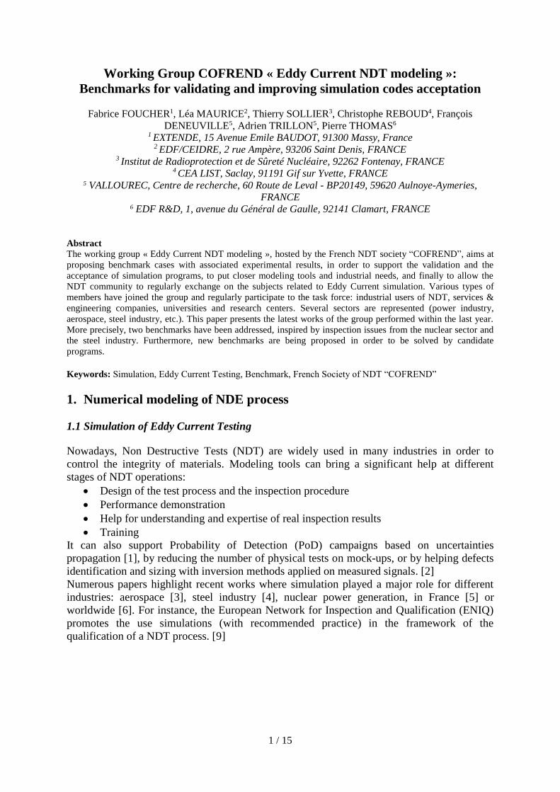
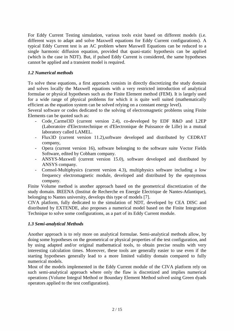
Input parameters relative to the part and the sensor are reported in table 1 & 2. A 2D view of
the sensor is shown in FIGURE 3.
Test piece Planar slab
FIGURE 2 : Sensor scanning vs notch
Thickness 1,55 mm
Material Inconel 600
Electrical conductivity 0,992 MS/m
Relative permeability 1
Reference Flaw F7 Target Flaw F5
Length 10 mm Length 2 mm
Aperture 0,3 mm Aperture 0.1 mm
Depth 40% Depth 100%
Calibration voltage 1V X
Calibration Phase 0° X Table 1 : B2 – Test piece and flaws parameters
Emitting Coil Receiving coil
Ferromagnetic core ferrite (B30) ferrite (B30)
Ferrite core dimensions 2.3 x 8 mm 2.3 x 8 mm
Lift-Off 0,3 mm
8 / 15
Ferrite relative permeability 1100 1100
Coil Internal Diameter 2.3 mm 2.3 mm
Coil External Diameter 2.8 mm 2.8 mm
Coil width 1.5 mm 1.5 mm
Number of turns 90 90
Emitter-Receiver Inter-axis distance 6 mm
Table 2 : B2 - Separated functions sensor parameter
6 mm
Noyaux en ferrite
Bobinages
FIGURE 3 : B2 – Separated functions sensor
This benchmark #2 has been solved with 3 different codes:
The semi-analytical software: CIVA – ET version 11.0,
The FEM software: Flux, version 11.1.2
The FEM code Code_Carmel3D, version 2.4.0, referenced C3D in table 3 and 4.
Two new features of CIVA v11.0 has been used in this benchmark, compared to the first
results given in previous papers on this benchmark [18]:
- Automatic mesh of the flaw,
- A specific surface model (Boundary Element Method) more efficient and more precise
for thin flaw than volume model.
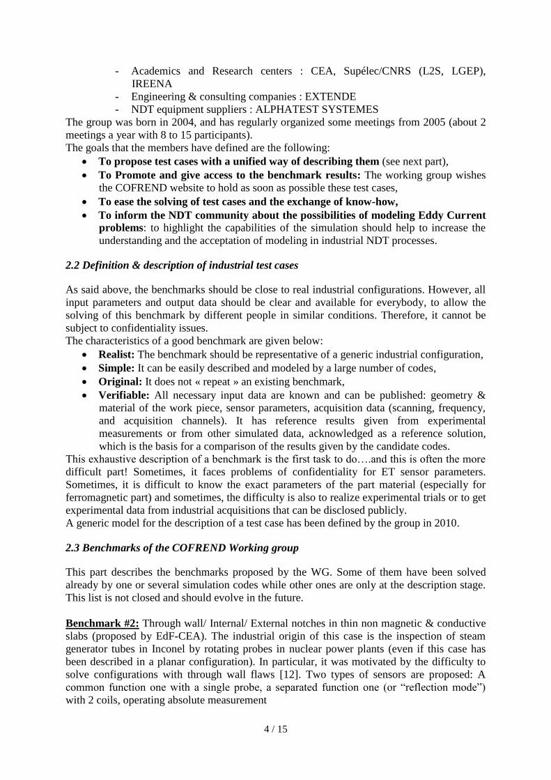
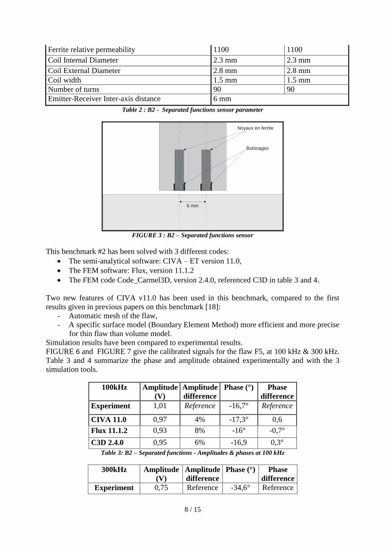
Simulation results have been compared to experimental results.
FIGURE 6 and FIGURE 7 give the calibrated signals for the flaw F5, at 100 kHz & 300 kHz.
Table 3 and 4 summarize the phase and amplitude obtained experimentally and with the 3
simulation tools.
100kHz Amplitude
(V)
Amplitude
difference
Phase (°) Phase
difference
Experiment 1,01 Reference -16,7° Reference
CIVA 11.0 0,97 4% -17,3° 0,6
Flux 11.1.2 0,93 8% -16° -0,7°
C3D 2.4.0 0,95 6% -16,9 0,3°
Table 3: B2 – Separated functions - Amplitudes & phases at 100 kHz
300kHz Amplitude
(V)
Amplitude
difference
Phase (°) Phase
difference
Experiment 0,75 Reference -34,6° Reference

9 / 15
CIVA 11.0 0,74 1% -33,4° -1,2°
Flux 11.1.2 0,70 7% -32,7° -1,9°
C3D 2.4.0 0,70 7% -34,4° 0,2°
Table 4: B2 – Separated functions - Amplitudes & phases at 300 kHz
FIGURE 4 – Simulated configuration in CIVA 11.0
FIGURE 5 – Configuration mesh in Flux 11.1
FIGURE 6 –Bench2- Signals on F5 at 100kHz
FIGURE 7 - Bench2- Signals on F5 at 300kHz
4.2 Benchmark #6
The benchmark #6 deals with online Eddy Current inspection of steel tubes without weld at
manufacturing stage. Therefore, this case addresses the needs of steel industry. Inspection
technique is based on encircling coils. Flaws are Flat Bottom Holes, Through Wall Hole or
grooves, as represented in FIGURE 8. This test-case involves 2 configurations for the tube:
“Centered case”: The tube is correctly centered in the inspection set. It corresponds to
optimal inspection configuration.
“Off-centered case“: With a shift of 2mm between the tube axis and the inspection
coils axis. This corresponds to a situation where the vibrations of the tube in the
inspection bench can produce such off-centering. More generally, it addresses a major
issue, which is the reproducibility of inspections in production.
Tube dimensions External Diameter : 32 mm - Thickness : 8 mm
Tube material : Stainless Steel TP304L / Conductivity : = 1,43 MS/m
Relative Permeability: 1
FBH 8 : Through Wall Hole (depth : 8 mm) Diameter : 3,5 mm

10 / 15
FBH 2 : Flat Bottom Hole, depth 2 mm. Diameter : 3,5 mm
FBH 3 : Flat Bottom Hole, depth 3 mm. Diameter : 3,5 mm
FBH 5: Flat Bottom Hole, depth 5 mm. Diameter : 3,5 mm
Circular groove : External circular groove ; Depth : 0,5 mm, Width: 1 mm Table 5 : B6 – Description of the configuration
The tube has an external diameter of 32mm and a thickness of 8mm. It is made of austenitic
stainless steel TP304L, containing mainly iron (~73%), chromium (~18%) and nickel
(~9%). Electromagnetic material properties, which are necessary to know for simulation, are
given in table 5, as well as the dimensions of the tube and flaws. Sensor parameters are listed
in table 6. The calibration is done on the Flat Bottom Hole of 3 mm depth.
FIGURE 8 : B6 – Representation of the configuration in CIVA
Emitting Coil Receiving Coils
Internal Diameter : 47 mm
Thickness : 2,4 mm
Width : 30 mm
Nbr Turns : 200
Internal Diameter : 41 mm
Thickness : 1 mm
Width : 2 mm
Nbr Turns: 200
Air gap between coils: 2mm (Configuration « 2-2-2 ») Table 6 : B6 – Coils parameters
Centered
FBH2
Amplitude
(V)
Amplitude
Difference Phase (°) Phase difference (°)
Experiment 0,92 Reference 97,9 Reference
CIVA 11.0 0,89 -3% 96,5 -1,4
Flux 11.1 0,90 -2% 96,4 -1,5°
Centered
FBH5
Amplitude
(V)
Amplitude
Difference Phase (°) Phase difference
Experiment 0,99 Reference 83,5 Reference
CIVA 11.0 1,01 2% 85,3 1,8
Flux 11.1 1,00 2% 86,0 2,5
Centered
FBH8
Amplitude
(V)
Amplitude
Difference Phase (°) Phase difference
Experiment 0,98 Reference 84,5 Reference
CIVA 11.0 0,99 0% 84,7 -0,2
Flux 11.1 0,98 0% 86,6 -2,1

11 / 15
Table 7 : B6 – Comparison between experimental results (reference) and simulations for the « centered case »
at 50kHz
12 / 15
Amplitude
(V)
Amplitude
difference Phase (°)
Phase difference
(°) Off-
centered
FBH2
CIVA 11.0 1,70 2,7%
102,3
-0,4° Flux 11.1 1,75 101,9
Off-
centered
FBH5
CIVA 11.0 1,92 1,4%
91,5
1,1° Flux 11.1 1,95 92,6
Off-
centered
FBH8
CIVA 11.0 1,88 1,8%
90,2
3° Flux 11.1 1,91 93,2
Table 8 : B6 – Comparison between simulated results for the « off-centered case” at 50kHz
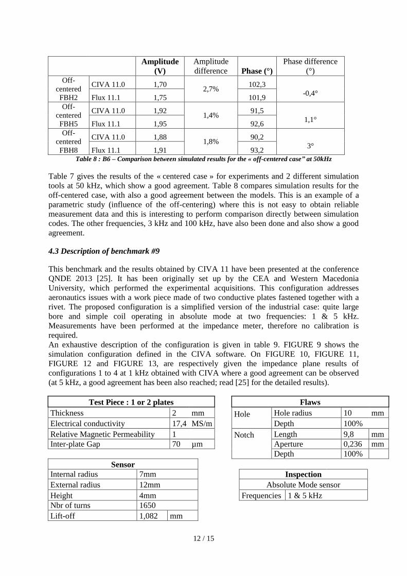
Table 7 gives the results of the « centered case » for experiments and 2 different simulation
tools at 50 kHz, which show a good agreement. Table 8 compares simulation results for the
off-centered case, with also a good agreement between the models. This is an example of a
parametric study (influence of the off-centering) where this is not easy to obtain reliable
measurement data and this is interesting to perform comparison directly between simulation
codes. The other frequencies, 3 kHz and 100 kHz, have also been done and also show a good
agreement.
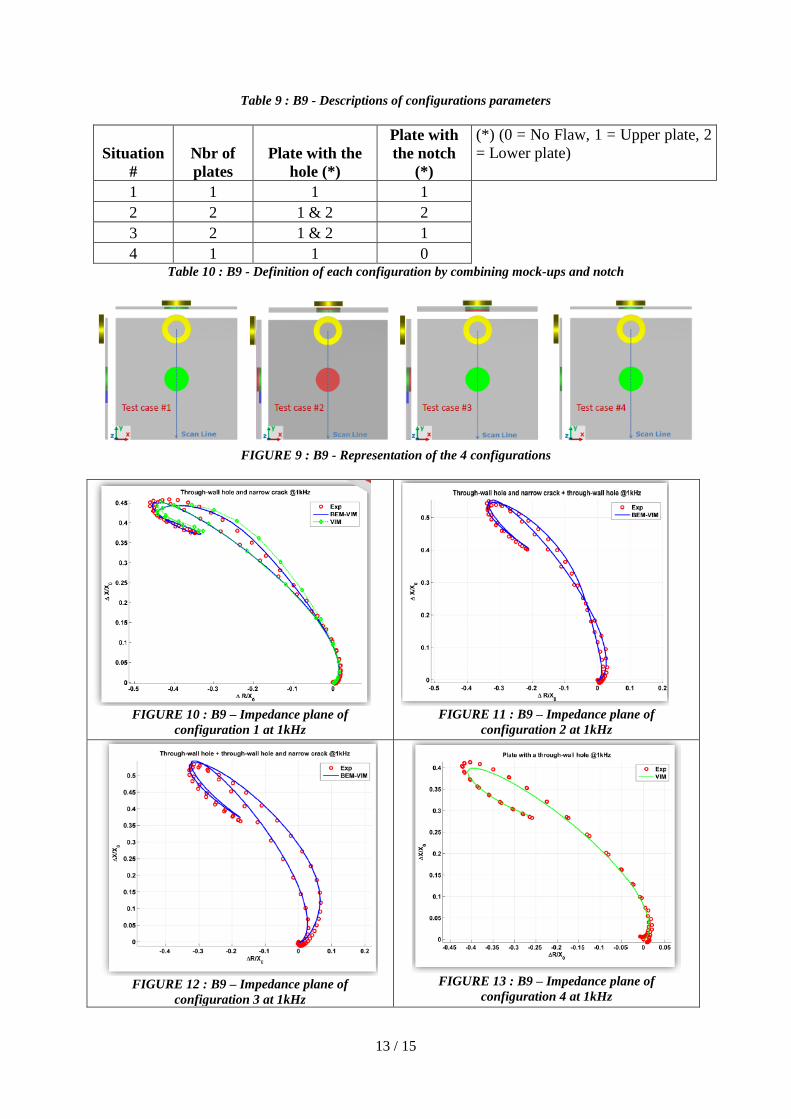
4.3 Description of benchmark #9
This benchmark and the results obtained by CIVA 11 have been presented at the conference
QNDE 2013 [25]. It has been originally set up by the CEA and Western Macedonia
University, which performed the experimental acquisitions. This configuration addresses
aeronautics issues with a work piece made of two conductive plates fastened together with a
rivet. The proposed configuration is a simplified version of the industrial case: quite large
bore and simple coil operating in absolute mode at two frequencies: 1 & 5 kHz.
Measurements have been performed at the impedance meter, therefore no calibration is
required.
An exhaustive description of the configuration is given in table 9. FIGURE 9 shows the
simulation configuration defined in the CIVA software. On FIGURE 10, FIGURE 11,
FIGURE 12 and FIGURE 13, are respectively given the impedance plane results of
configurations 1 to 4 at 1 kHz obtained with CIVA where a good agreement can be observed
(at 5 kHz, a good agreement has been also reached; read [25] for the detailed results).
Test Piece : 1 or 2 plates
Flaws
Thickness 2 mm
Hole
Hole radius 10 mm
Electrical conductivity 17,4 MS/m
Depth 100%
Relative Magnetic Permeability 1
Notch
Length 9,8 mm
Inter-plate Gap 70 µm
Aperture 0,236 mm
Depth 100%
Sensor Internal radius 7mm
Inspection
External radius 12mm
Absolute Mode sensor
Height 4mm
Frequencies 1 & 5 kHz
Nbr of turns 1650
Lift-off 1,082 mm
13 / 15
Table 9 : B9 - Descriptions of configurations parameters
Situation
#
Nbr of
plates
Plate with the
hole (*)
Plate with
the notch
(*)
(*) (0 = No Flaw, 1 = Upper plate, 2
= Lower plate)
1 1 1 1
2 2 1 & 2 2
3 2 1 & 2 1
4 1 1 0
Table 10 : B9 - Definition of each configuration by combining mock-ups and notch
FIGURE 9 : B9 - Representation of the 4 configurations
FIGURE 10 : B9 – Impedance plane of
configuration 1 at 1kHz
FIGURE 11 : B9 – Impedance plane of
configuration 2 at 1kHz
FIGURE 12 : B9 – Impedance plane of
configuration 3 at 1kHz
FIGURE 13 : B9 – Impedance plane of
configuration 4 at 1kHz
14 / 15
5. Conclusion
Numerical simulation can be very helpful to solve industrial issues at different stages of a
NDT process. However, to use them with confidence, one or several validation steps are
necessary.
The working group from the French Society of NDT « COFREND » aims at proposing
realistic benchmarks for Eddy Current Testing, close to industrial needs, allowing to validate
the code by comparison with experimental data and/or simulation codes.
This article also highlights the evolution of computation performance for the last 20 years,
showing a real improvement of calculation times while an increase in the modeling
capabilities (type of cases to be solved, size of mesh “allowed” with FEM models, etc.). This
will allow modeling software to address more and more complex situations in a limited
amount of time allowing extensive parametric studies to be performed. It should help to
improve again the development and optimization of inspection method while improving their
reliability.
The exhaustive list of test cases proposed by the group is given in this paper. While some of
them are still in the description stage, the results of 3 benchmarks are given in this paper
showing an overall good agreement.
While helping to validate the accuracy of simulation results by comparison with experimental
data, another benefit of the working group activity is to underline the necessity to describe
exhaustively a simulation configuration, and in particular, the importance of mastering all
influential input parameters.
In the coming years, the working group will continue to propose benchmarks, will inform the
community about the results obtained and the improvement of simulation performance, in
order to help the acceptation of simulation software in the NDT industry.
References [1] Bilicz, S.; Vazquez, E.; Gyimothy, S.; Pavo, J.; Lambert, M., "Kriging for Eddy-Current Testing
Problems," Magnetics, IEEE Transactions on, vol.46, no.8, pp.3165, 3168, Aug. 2010, doi:
10.1109/TMAG.2010.2043418
[1b] Dominguez, N., Reboud, C., Dubois, A. and Jenson, F., Dominguez, N., A New Approach of
Confidence in POD Determination Using Simulation, AIP Conf. Proc. 1511, 1749 (2013);
http://dx.doi.org/10.1063/1.4789252.
[2] http://www.agence-nationale-recherche.fr/projet-anr/?tx_lwmsuivibilan_pi2[CODE]=ANR-13-
MONU-0011
[3] Reverdy, F., Dominguez, N., NDT Modeling tools applied to the aeronautic industry: examples in
CIVA, 5th International Symposium on NDT in Aerospace, 13-15th November 2013, Singapore
[4] Bisiaux, B., Maurice, L, Paillard, S., Comparison Of Two Eddy Current Simulation Methods In
Steel Pipes, ICNDE 2013 Ljubljana Slovénie
[5] Hubert C., Deydier, S., de Roumilly L., Lhuillier, P.-E., Chassignole, B., "Use Of Advanced
Simulation Tools: Some Examples In The French Qualification Process For Ultrasonic Applications",
ICNDE 2013.
[6] “EPRI Launches NDE Modeling and Simulation Center to Enhance Nondestructive Evaluation »,
http://mydocs.epri.com/docs/CorporateDocuments/Newsletters/NUC/2011-07/07a.html
http://www.agence-nationale-recherche.fr/projet-anr/?tx_lwmsuivibilan_pi2%5bCODE%5d=ANR-13-MONU-0011

15 / 15
[7] Li, Y., Berthiau, G., Feliachi, M., Cheriet, A., 3D Finite Volume Modeling of ENDE Using
ElectromagneticT-Formulation, Hindawi Publishing Corporation, Journal of Sensors, Volume 2012,
Article ID 785271,
[8] Rubeck, C., Bannwath, B., Chabedec, O., Guichon, J-M., Delinchant, B., Yonnet, JP, Compression
par ondelettes de formulations intégrales sur architecture GPGPU, Numelec 2012.
[9] ENIQ, ENIQ Recommended Practice 6: the Use of Modeling in Inspection Qualification, ENIQ
report No. 45, vol. 6, 2nd issue, 2011.
[10] Turner, LR., The TEAM Workshops : What’s Old? What’s New? Asian TEAM Workshop,
Yichang City, China, October 13-14, 1996
[11] Takagi, T., Uesaka, M., Miya, K., Electromagnetic NDE research activities in JSAEM, ENDE
1996, Tokyo, IOS Press, pp. 9-16.
[12] Moreau, O., Gilles-Pascaud, C., Reboud, C., Démarche de validation de code de simulation en
END par courants de Foucault, Journées COFREND 2008 (TOULOUSE)
[13] Zorni, C., Reboud, C., Decitre, J.M., Santandréa, L., Le Bihan,Y., Ventre, L., Tamburrino , A.,
and Lambert, M., "Modelling eddy current testing of ferromagnetic medium", International Journal of
Applied Electromagnetics and Mechanics, vol.39, no.1, pp.245-250, Jan. 2012 doi : 10.3233/JAE-
2012-1467.
[14] Maurice, L., Costan, V., Guillot, E., Thomas, P, Using simulation tools for performance
demonstrations of eddy current NDE Wears on Steam Generator Tubes, QNDE 2012
[15] Mayos, M., Levy, R., Sollier, T., Tretout, H., Betsch, N., Foucher, F., Lepaul, S., Neau, G.,
Nicolas, A., Premel, P., Groupes de Travail COFREND en END par courants de Foucault : bilan et
perspectives, Journées COFREND, Beaune, Mai 2005.
[16] Le Ber, L., Calmon, P., Sollier, T., Mahaut, S., Benoist, P., Advances of simulation and expertise
capabilities in CIVA platform, LQNDE Vol. 25, 2006, pp. 684-691
[17] Miorelli, R.; Reboud, C.; Lesselier, D.; Theodoulidis, T., "Eddy Current Modeling of Narrow
Cracks in Planar-Layered Metal Structures," Magnetics, IEEE Transactions on Magnetics, vol.48,
no.10, pp.2551-2559, Oct. 2012 doi: 10.1109/TMAG.2012.2197403
[18] Mayos, M., Moreau, O., Costan, V., Gilles-Pascaud, C., Reboud, C., Buvat, F, “A Benchmark-
based Approach For The Validation Of Eddy Current Simulation Codes In Support Of Nuclear
Power Plants Inspection, ENDE 2009.
[19] Mayos, M., Moreau, O., Costan, V., Gilles-Pascaud, C., Reboud, C., Buvat, F.,Developing and
using benchmarks for eddy current simulation codes validation to address industrial issues, QNDE
2010.
[20] Mayos M., Sollier T., Lambert M., Gilles-Pascaud C., Moreau O., Dessendre M., Deneuville F.,
Reboud C., Foucher F., Mistral Q., Debroise M., Levy R., Multi-domain industrial benchmarks for
eddy current modeling: the COFREND working group, Proceedings of ECNDT2010, Moscow, 2010.
[21] Deneuville, F., Desdoit, E., Bisiaux, B., Mayos, M., Comparaison De Deux Méthodes De
Simulation Des Contrôles Par Courants De Foucault Sur Tubes En Acier, COFREND 2011.
16 / 15
[22] Deneuville, F., Reboud, C., Foucher, F., Lesselier, D., Maurice, L., Comparison of Two Modeling
Approaches of Eddy Current Industrial Non-Destructive Testing of Steel Pipes, QNDE 2013.
[23] Skarlatos, A.; Pichenot, G.; Lesselier, D.; Lambert, M.; Duchene, B., "Electromagnetic Modeling
of a Damaged Ferromagnetic Metal Tube by a Volume Integral Equation Formulation," Magnetics,
IEEE Transactions on , vol.44, no.5, pp.623,632, May 2008
doi: 10.1109/TMAG.2008.918206
[24] Miorelli, R., Reboud, C., Theodoulidis, T., Solution to the WFNDEC 2013 Eddy Current
Benchmark Problem Via a Coupled VIM - BEM Approach, Department of Mechanical Engineering,
Kozani, Greece. http://www.wfndec.org
[25] Mayos, M., Lambert, M., Gilles-Pascaud, C., Dessendre, M., Dominguez, N., Foucher, F.,
Abakar, A., Groupe De Travail Cofrend Sur La Simulation Des End Par Courants De Foucault - Bilan
D'activites, COFREND 2008.