

Working between the hook and the load - Amzone -...
68
2015 Product Catalogue for UK & ROW Safe Lifting Solutions Working between the hook and the load
Transcript of Working between the hook and the load - Amzone -...

Email: [email protected] www.modulift.com
2015 Product Cataloguefor UK & ROW
Safe Lifting Solutions
Working between the hook and the load

Email: [email protected] www.modulift.com
27
Mod 600XA/400 28
MOD 600XA/500 29
MOD 600XA/600 30
MOD 600XA/800 31
MOD 600XB/500 32
MOD 600XB/800 33
MOD 600 B/1000 34
Email: [email protected] www.modulift.com
Modulift UK LtdModulift Sets 03
Modulift Spreader Beams 04
One Beam Many Lifts 05
The Standard Range 06
The Heavy Range 07
Regs, Standards & Compliance 08
Enhanced QA/Custom Design 09
Accessories 10
Design Engineering & Lift Management 12
QuickJoint 2 15
Mod 6 16
Mod 12 17
Mod 24 18
Mod 34 19
Mod 50 20
MOD 50/24 Step-Downs 21
MOD 50/12 Step-Downs 22
MOD 50/6 Step-Downs 23
Mod 70 24
Mod 70H 25
MOD 70/34 Step-Downs 26
MOD 70/24 Step-Downs 27
Mod 110 28
Mod 110H 29
Mod 110SH 30
MOD 110/70 Step-Downs 31
MOD 110/50 Step-Downs 32
Mod 250/250 33
Mod 250/300 34
Mod 250/400 35
MOD 250/110H Hybrid 36
MOD 250/110 Hybrid 37
MOD 250/70H Hybrid 38
MOD 250/70 Hybrid 39
Mod 400/400 40
Mod 400/500 41
Mod 400/600 42
MOD 400/250 Hybrid 43
MOD 400/110SH Hybrid 44
MOD 400/110H Hybrid 45
MOD 400/110 Hybrid 46
MOD 600XB/400 47
MOD 600 XB/600 48
MOD 600 XB/800 49
MOD 600 XB/1000 50
MOD 800J/1000 51
CMOD Spreader Frame Range 52
CMOD 6 53
CMOD 12 54
CMOD 24 55
CMOD 34 56
CMOD 50 57
CMOD 70 58
CMOD & Beyond 59
Lattice Spreader Beams 60
11 New Fields Business ParkStinsford Road, PooleDorset BH17 0NF
Tel: +44 (0) 1202 621511Fax: +44 (0) 1202 632811Email: [email protected]: www.modulift.com
Contents
2
Lattice SF 6-24m 61
Lattice SF 27m 62
Lattice SF 30m 63
Lattice SF 33m 64
Lattice SF 36m 65
Lattice SF 42m 66
Where To Buy & Contacts 67
Professional Bodies & Regulatory Standards

Email: [email protected] www.modulift.com
11 New Fields Business ParkStinsford Road, PooleDorset BH17 0NF
Tel: +44 (0) 1202 621511Fax: +44 (0) 1202 632811Email: [email protected]: www.modulift.com
3
Heavy
MOD 110Up to 110 t at 11m/37ftUp to 16m/52ft at a lower capacity.
MOD 250/300Up to 300t at 12m/40ft Up to 20m/66ft at a lower capacity.
MOD 400/600Up to 600t at 12m/40ftUp to 23m/76ft at a lower capacity.
MOD 110HUp to 170t at 8m/26ftUp to 16m/52ft at a lower capacity.
MOD 250/400Up to 400t at 8m/28ft Up to 20m/66ft at a lower capacity.
MOD 600/600Up to 600t at 21m/70ftUp to 26m/85ft at a lower capacity.
MOD 110SHUp to 240t at 6m/20ft Up to 16m/52ft at a lower capacity.
MOD 400/400Up to 400t at 16m/55ftUp to 23m/76ft at a lower capacity.
MOD 600/800Up to 800t at 18m/60ftUp to 26m/85ft at a lower capacity.
MOD 250/250Up to 250t at 13m/45ft Up to 20m/66ft at a lower capacity.
MOD 400/500Up to 500t at 14m/47ftUp to 23m/76ft at a lower capacity.
MOD 600/1000Up to 1000t at 15m/51ftand up to 26m/85ft at a lower capacity.
Modulift Sets
The most cost efficient way topurchase the Modulift System is inthe predetermined sets. This will allowyou to interchange components ineach set to gain the full range of spansavailable. This table shows the basicproduct range and gives you a quickguide to their specification and retailprice.
The remainder of this catalogue willlook at the full range of products andsupport services in more detail. If theinformation you need is not withinthese pages then pick up the phone orsend us an email we will be pleased tohelp you.
Standard
QJ2Up to 2t at 1.2m/4ft
MOD 34Up to 34t at 5m/17ftUp to 8m/26ft at a lower capacity.
MOD 6Up to 6t at 2.5m/8ft
MOD 50Up to 50t at 7.5m/25ftUp to 11m/36’ft at a lower capacity.
MOD 12Up to 12t at 4m/13ft
MOD 70Up to 70t at 9m/29ftUp to 12m/40’ft at a lower capacity.
MOD 24Up to 24t at 4.5m/14ftUp to 6m/20ft at a lower capacity.
MOD 70HUp to 100t at 8m/25ftUp to 12m/40ft at a lower capacity.

Email: [email protected] www.modulift.com
Modulift Spreader Beams
MOD 110/110H
MOD 110SH
MOD 250
MOD 600
MOD 400
Modulift offer a wide range of Modular Spreader Beam components, offering a variety of different spans for all your lifting needs.
The sizes range from 2 to 5,000t with spans available from 0.4m/1’4” - 100m/300’
The flexibility of the modular configuration enables our Spreader Beams to be reused time and time again, providing a cost-effective solution.
What Size Beam Do I Need?
Simple! First select the span you require, then select the SWL you need for that span.
Please see tables on pages 6 & 7
to select your beam.
Part of the Modulift Standard Range
Part of the Modulift Heavy RangeRange Classification
Range Modulift Sizes
Standard 6, 12, 24, 34, 50, 70, 70H
Heavy 110, 110H, 110SH, 250, 400, 600
4

Email: [email protected] www.modulift.com
One Beam Many Lifts
For Larger Lighter LoadsFor longer spans and lighter loads, additional components are available allowing you to optimise the weight of our higher capacity range of Modular Spreader Beams to carry out these lifts. These struts provide the backbone of our Spreader Beams when trying to achieve longer spans. We have two solutions that can make the system more flexible and cheaper for you by interchanging smaller capacity End Units and Drop Links.
• Step-Down End Units are designed for smaller sizes, up to the MOD 70• Cone Adaptors accommodate the larger sizes
These additional components allow your existing Spreader Beam to become even more versatile over a number of lifts so you can remain cost-effective with your rigging and crane capacity requirements.
By stepping down the End Units to a more suitable capacity, you can optimise your Shackles and Slings to provide a lighter system overall.
There are a number of ways you can utilise our Modular Spreader Beams, for example;
Need a span of 20m/66’ but are only lifting 70t - we can provide you with a MOD 250/70 giving you Cone Adapters and MOD 70 End Units to bolt to MOD 250 struts to achieve the required overall Spreader Beam system.
Need to lift 24t but at 12m/40’ - change our standard MOD 70 Spreader Beam End Units to Step-Down End Units and decrease the SWL to 24t allowing you to use smaller Shackles and Slings with the MOD 70 struts.
Need to lift 100t– if you already have a MOD 70 Spreader Beam, by changing the End Units to the MOD 70H End Units you can increase the SWL to 100t negating the need to buy a completely brand new Spreader Beam.
Using one of our Modular Spreader Beams enables you to be more flexible over a number of lifts without needing to buy a new Spreader Beam every time, our lightweight design also minimises the overall weight of the lifting
equipment and the costs incurred whilst working between the hook and the load.
Interchangeable Components
5

Email: [email protected] www.modulift.com
TOP: 25tLOWER: 17t
The Standard Range
6
MOD 50
MOD 34
MOD 24
STRUT
SPREaDER SySTEM 0.1M 0.2M 0.25M 0.3M 0.5M 0.6M 0.75M 1.0M 1.5M 2.0M 3.0M 4.0M 6.0M EnD UnIT
DROPLInK
MOD 6 1 1 1 1 1 2 2
MOD 12 1 1 1 1 1 2 2
MOD 24 1 1 2 2 2
MOD 34 1 1 3 2 2
MOD 50 1 1 1 2 2 2
MOD 70/70H 1 1 1 2 2 2
MOD 110/110H/110SH 1 1 1 3 2 2
MOD 250-250/250-300/250-400 1 1 1 2 2 2
MOD 400-400/400-500/400-600 1 1 1 3 2 2
MOD 600-600/600-800/600-1000 1 1 1 3 2 2
Components per Set
* Please note: Custom length Struts are available on request
0
5
10
15
20
25
30
35
40
45
50
55
60
65
70
75
80
85
90
95
100
0.5 1 1.5 2 2.5 3 3.5 4 4.5 5 5.5 6 6.5 7 7.5 8 8.5 9 9.5 10 10.5 11 11.5 12
Capa
city (m
)
Chart Title
Mod 70H
MOD 70
MOD 50
MOD 34
MOD 24
MOD 12
MOD 6
Load v Span Chart - Modulift Spreader Beam Standard Range
SWL/
tonn
es @
60º
BSA
/60º
ISA
/30º
STV
Span (m)
MOD 6
MOD 12
MOD 24
MOD 34
MOD 50
MOD 70
MOD 70H
Email: [email protected] www.modulift.com
0 25 50 75
100 125 150 175 200 225 250 275 300 325 350 375 400 425 450 475 500 525 550 575 600 625 650 675 700 725 750 775 800 825 850 875 900 925 950 975
1000
2 3 4 5 6 7 8 9 10 11 12 13 14 15 16 17 18 19 20 21 22 23 24 25 26
SWL
/ to
nnes
@ 3
0 deg
rees
BSA
/ 6
0 deg
ree
ISA /
30
deg
ree
STV
Span (m)
Load < Span = >od?@AB Cea<D Eange
MOD 110
MOD 110H
MOD 110SH MOD 250/250
MOD 250/300
MOD 250/400 MOD 400/400
MOD 400/500
MOD 400/600 MOD 600/600
MOD 600/800
MOD 600/1000
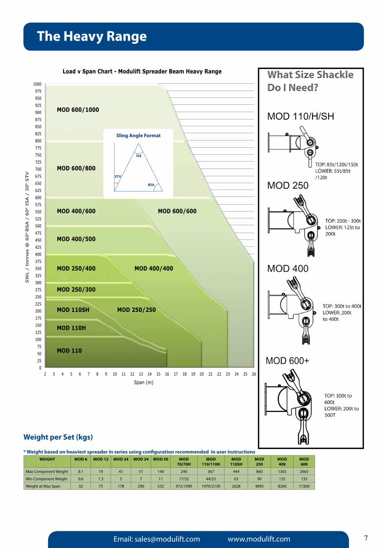
Load v Span Chart - Modulift Spreader Beam Heavy Range
Span (m)
SW
L /
tonnes
@ 6
0° BSA /
60
° IS
A /
30
° STV
TOP/LOWER:Consult Modulift for Shackle sizes
Weight per Set (kgs)
* Weight based on heaviest spreader in series using configuration recommended in user instructions
Email: [email protected] www.modulift.com
The Heavy Range
7
Sling Angle Format
BSA
ISA
STV
WEIGHT MOD 6 MOD 12 MOD 24 MOD 34 MOD 50 MOD 70/70H
MOD 110/110H
MOD110SH
MOD250
MOD400
MOD 600
Max Component Weight 8.1 19 41 51 140 240 367 444 860 1365 2665
Min Component Weight 0.6 1.3 5 7 11 17/32 44/55 63 90 135 135
Weight at Max Span 32 75 178 290 532 972/1090 1970/2130 2628 4895 8260 17260

Email: [email protected] www.modulift.com
Regulations, Standards & Compliance
Each Modulift Spreader Beam series has been proven by being Proof Load Tested in the Modulift compression test rig and all products comply with the relevant standards as detailed below:
UK & Europe ComplianceAll our Spreader Beams have been designed in accordance with:
• BS En 13155: 2003+A2:2009: Cranes – Safety – non- fixed load lifting attachments• DnV Standard for Certification no. 2.22 Lifting Appliances 2011• Mod 6 up to Mod 800/1000 Type Approved by DnV• LOLER: 1998 (Lifting Operations and Lifting Equipment Regulations)• PUWER: 1998 (Provision and Use of Work Equipment Regulations)• EC Machinery Directive 2006/42/EC• BS En 1993-1: 2005: Eurocode 3
USa Compliance• ASME B30.20 - 20103 For Below-the-Hook Lifting Devices.• ASME BTH-1 2011: Design of Below-the-Hook Lifting Devices.
australia Compliance• AS 4991 - 2004: Lifting Devices.
DNV Standard for CertificationDnV 2.22: Modulift Spreader Beams designs conform to DnV Standard for Certification no.2.22 Lifting Appliances. Modulift is the first and only Spreader Beam Manufacturer in the world to have the globally recognised DnV Type Approval for all Spreader Beams up to 1000t capacity in accordance with DnV’s standard for Certification no. 2.22 for Lifting Appliances 2011, at no extra cost to the client.
For those customers who require a higher level of quality standard, Modulift also provides further options for project specific 3rd party verification.
When a project demands the highest level of certification Modulift are able to offer our customers varying degrees of additional DnV certification depending upon their individual QA requirements, including:
•ProofLoadTestSurveyReportandRecordofTest•DNVCertificateofConformityforManufacture&Test (CG3 in accordance with ILO convention 152)
8
ask Modulift about the Level of Options available to Ensure your Safe Lift
Level 1. Standard Modulift Spreader Beams In accordance with BS En 13155 - 2003. Available CE Marked and supplied with a Certificate of Conformity, up to 400t available off-the-shelf.
Level 2. Individual Proof Load Testing of Modulift Spreader Beams Modulift offer an individual Proof Load Test service with or without 3rd party verification to those requiring a higher level of certification. Please ask for further information.
Level 3. Modulift Spreader Beams with project specific DNV Certification Although our range Spreader Beams are now DnV Type Approved, we can also offer project specific DnV certification of individual Spreader Beams.
It is the ultimate in certification and quality control for the most demanding project specification; a Modulift Spreader Beam individually certified by DnV in terms of design, manufacturing and Proof Load testing. Supplied with a design review report and Certificate of Conformity for Manufacture and Test, issued by DnV.
We now have all our Spreader Beams up to
1000t capacity DNV Type approved.
Please ask about these additional services at the time of your enquiry.

Email: [email protected] www.modulift.com 9
Enhanced Qa Options/Custom Design Solutions
MOD 400
MOD 600
MOD 1000
MOD 1600
Product Specification
Off-the-Shelf Enhanced Qa Options
Design
BS En 13155 - 2003, BS En 1993-1 - 1- 2005
ASME B30.20 - 2010, AS 4991 - 2004, DnV 2.22
Project Specific requirements
Materials Impact tested to -20° C /-4°F in accordance with BS En10025/10210/10219
Impact tested to -40° C /-40°F in accordance withBS En 10025/10225/API SL
Welding BS En ISO 15614.1
Paint Finish Standard Finish - Yellow RAL 1003 2 Pack epoxy paint system
High build systems suitable for marineenvironments
Markings Engraved stainless steel ID plate ID plate and additional labelling
Testing - Proof Load Testing & nDT
Bolts Grade 8.8 HT zinc plated Low temperature, galvanised
Shackles Rated to -20° C /-4°F Rated to -40° C /-40°F
Slings Rated to -40° C/ -40°F and BS En 13414 -1 & -3 compliant
Modulift recognise the high level QA requirements of the Oil & Gas, Offshore and Renewable Energy industries. In response to these high standards Modulift offer Enhanced QA Options to our standard Off-the-Shelf range of Spreader Beams - see our options list below.
MOD 600
MOD 1000
Verification Off-the-Shelf Enhanced Qa Options
DNV Type approval √ √
DNV Design approval √ √
Original Design Verification Proof Load Test √ √
Job specific Proof Load Testing & NDT on individual beams x √
Third Party Verification of individual beams x √
Certification / Documentation Off-the-Shelf Enhanced Qa Options
EC Declaration of Conformity √ √
User Instructions √ √
Material Certification x √
Inspection and Test Plan (ITP) x √
Welding, NDT & Proof Load Testing documentation x √
MRB (Manufactures Record Book) x √

Email: [email protected] www.modulift.com
accessories
Summary of the sizes of Shackles that are required for the Modulift Modular Spreader Beam Range:
10
SHaCKLES & SLINGS
Modulift can supply shackle sets and slings to suit all rigging requirements. Sling Types: Round Slings, Chain Slings, Flat Webbing Slings, Wire Rope Slings and Cable Laid Slings & Grommets to BS En 13414-1 & 3. Shackles generally conform to En 13889 and US Fed Spec RR-C-271.
Modulift Spreader Series
Bottom Shackle Size
Top Shackle Size
Van Beest Model Number
The Crosby Group Model Number
MOD 6 3.25t 4.75t G - 4163 G - 2130
MOD 12 6.5t 8.5t G - 4163 G - 2130
MOD 24 12t 17t G - 4163 G - 2130
MOD 34 17t 25t G - 4163 G - 2130
MOD 50 25t 35t G - 4163 G - 2130
MOD 70 35t 55t G - 4163 G - 2130
MOD 70H 55t 85t G - 4163 G - 2130
MOD 110 55t 85t G - 4163 G - 2130
MOD 110H 85t 120t G - 163/P-6036 G - 2130
MOD 110SH 120t 150t P - 6036
MOD 250 125t-200t 200t-300t P - 6033
MOD 400 200t-400t 300t-400t P - 6033
MOD 600 200t-500t 300t-600t P - 6033
All Modulift shackles recommended are
DNV Type approved.

Email: [email protected] www.modulift.com
Summary of the sizes of Shackles that are required for the Modulift Modular Spreader Beam Range:
DROP LINK aCCESSORIES - DELTa PLaTES aND CLEVIS DROP LINKS
A range of alternatives to standard Drop Links are available to help you with your rigging needs. Clevis Drop Links will rotate the shackle orientation by 90 degrees. Delta Plates enable 2 slings to be connected with separate shackles.
DROP LINK aSSEMBLy aIDSThe Modulift Drop Link Assembly Aids are a tool used when rigging drop links into heavier Spreader Beams. It enables the drop link to be supported and aligned in position while a shackle is being fitted. Drop Link Assembly Aids are available for the MOD 250 and larger sizes (must be asked for at time of ordering).
STEP DOWN END UNITS aND CONE aDaPTORSFor requirements with longer spans and lighter loads, these enable a Spreader System to be optimised to suit a particular need. Step Down End Units are designed for smaller sizes up to MOD 70.Cone Adaptors are used for the larger sizes.
accessories
LOGISTIC CRaDLES
Modulift Logistic Cradles are an essential part of safe and efficient handling and storage of Modulift Systems.Designed with a storage position for each component, the cradles enable instant recognition of any missing components.Cradles can be produced to suit any rig combination. Other design features can include fork pockets, stacking feet, lift-ing points, tool storage and security cases for locking.
FaSTENERSModulift bolts, nuts and washers are specifically supplied for each Spreader Beam assembly; see individual User Instructions in the following pages for details.Additional fasteners that are Modulift approved can be purchased at any time.
11

Email: [email protected] www.modulift.com
Engineering Design and Lift Management
With over 20 years of specialist lifting experience, Modulift is expert in designing and manufacturing any manner of complicated or excessively heavy lifting project. At the forefront of every lift, Modulift maintains the very highest standards of risk management while ensuring a safe lifting environment.
With a team of highly trained specialist in-house Lifting Engineers, Project Consultants, Rig Planning Services and On-Site Support, Modulift can deliver an extensive personalised package which will guide you through from your initial enquiry up to the day of your successful lift.
Using amongst the most Quality Assured products in the lifting industry, Modulift can design and build to the very highest global standards. Enhanced with a custom integrated service, Modulift can ensure a safe, cost efficient lift on time, every time.
12
Custom lifting solutions; innovative, approved safety, effective, on budget and on time
1. Simple Single Beam 2 point LiftA single Spreader Beam is the simplest configuration and is suitable for 2 point lifts. The Spreader Beam absorbs the compression forces to protect the load being lifted.
2. Single Beam 4 Point LiftThis configuration again used a single beam where the load being lifted has four individual lifting points.
3. 1-Over-2 RigWe use this configuration when vertical slings are essential for 4 point lifts. By varying the sling lengths, we can also take into account an offset center of gravity.
4. 1-Over-2 Inline RigIdeal for those lifts where the span is long and potential bending of the load is a problem. Further cascading layers are available to increase the number of lifting points
Lifting solutions made easy

Email: [email protected] www.modulift.com
Engineering Design and Lift Management
13
5. 1-Over-1Where there are an uneven number of points to lift from a 1 over 1 system can be used to lift the load whilst still providing a balanced rig.
6. Various Multi Spreader Beam RigsWith our expert help we can address most lifting issues using a combination of our products to fit the application and the circumstances.
7. CMOD Spreader Frame The CMod spreader frame uses corner units to connect existing Modulift struts into a 4 point modular spreader frame. This uses less headroom than a 1 over 2 rig.
8. Lifting Frame (H Frame)For extremely low headroom applications, Modulift can design and fabricate a bespoke lifting frame to suit your exact requirements
Using these Rig Design options, Modulift can provide purpose-built lifting equipment which takes in to account all the necessary elements such as load type and weight, height restrictions, environmental factors, Centre of Gravity composition for example, to deploy a safe and strategic lift. Modulift team members are available and on-hand every step of the way, assisting in producing an effective and smooth-running project.

Email: [email protected] www.modulift.com
Engineering Design and Lift Management
Modulift Custom Process Flow
Call today to discuss your Custom Designed & Managed Lifting Project
Tel: +44 (0) 1202 621511
14

Email: [email protected] www.modulift.com 15
45° STV RecommendedConfiguration.
EU - End Unit (0.15m)
30° STVSpan/
mSWL
/ t
Min.Top Sling Length
/ m
Span/ m
SWL/ t
Min.Top Sling Length
/ m
300 2 0.25 EU EU 300 2 0.3
400 2 0.28 EU 100 EU 400 2 0.4
500 2 0.36 EU 200 EU 500 2 0.5
600 2 0.43 EU 300 EU 600 2 0.6
700 2 0.50 EU 300 100 EU 700 2 0.7
800 2 0.57 EU 300 200 EU 800 2 0.8
900 2 0.64 EU 300 300 EU 900 2 0.9
1000 2 0.71 EU 300 300 100 EU 1000 2 1.0
1100 2 0.78 EU 300 300 200 EU 1100 2 1.1
1200 2 0.85 EU 100 300 300 200 EU 1200 2 1.2
Load v Span
QuickJoint 2
What is a QuickJoint? - “It’s only the future” says Modulift
The QuickJoint 2 (QJ2) is the smaller addition to the Modulift Spreader System. QuickJoint has a similar arrangement to the standard Modulift Spreader System and retains all the flexibility with the improved ability to be assembled quickly.
The compact size and lightness of the QuickJoint brings a new reality that Spreader Beams don’t have to be bulky and difficult to take to site. The convenient carry case will ensure that QuickJoint is easy to store, transport and used in applications such as in machinery assembly, installation and maintenance.
aPPLICaTIONS:• MechanicalandMachineryInstallation• MechanicalandMachineryMaintenance• AerospaceMaintenance• Ship’sMachineryMaintenance• ProcessEquipmentMaintenance
QJ2: WLL 2 Tonnes to 1.2m
FEaTURES:• FastassemblyduetoQJ2design• Lightweight:Lessthan8kg• HandycarrycaseenablestheQJ2tobe easily moved to a worksite before assembly BENEFITS:• QJ2’slightweightaidscompliancewith Manual Handling Regulations and PUWER• Rapidassembly
TYPICAL QUICKJOInT ASSEMBLY
QUICK RELEASE PIn:
QuickJoint 2 - The future of portable beams1. you Wanted Fast assemblyWe wanted to give you a Spreader System that is quick and simple to assemble and so our team came up with the QuickJoint Design!
2. Strong But LightweightThe entire set of components weighs less than 8 kgs for true portability and great durability
3. Handy Carry CaseOur carry case enables the QuickJoint to be easily moved to a worksite before assembly.
4. Multiple applicationsQJ2 can be used for a variety of applications, including installation, maintenance, aerospace and process equipment maintenance.

Email: [email protected] www.modulift.com16
MOD 6
The MOD 6 Series is modular in length and each system consists of one pair of end units and drop links, with intermediate struts that can be assembled to achieve different spans. The MOD 6 has an assembled span ranging from 400mm to 2.5m which can be achieved in 100mm increments.
PaRT REF: DESCRIPTION
P1 EnD UnIT
P2 DROP LInK
P3 1m STRUT
P4 0.6m STRUT
P5 0.3m STRUT
P6 0.2m STRUT
P7 0.1m STRUT
P8 4.75t SHACKLE
P9 3.25t SHACKLE
P10 M10X30, GRADE 8.8, HT BOLTS, nUTS & WASHERS
Component list
Load v Span
STRUT
Span / m
SWL/ t
Top Min Sling
Length / m
Span / m
SWL/ t
Min Top Sling
Length / m
400 6 0.3 EU EU 400 6 0.4
500 6 0.4 EU 100 EU 500 6 0.5
600 6 0.5 EU 200 EU 600 6 0.6
700 6 0.5 EU 300 EU 700 6 0.7
800 6 0.6 EU 300 100 EU 800 6 0.8
900 6 0.7 EU 300 200 EU 900 6 0.9
1000 6 0.7 EU 600 EU 1000 6 1.0
1100 6 0.8 EU 600 100 EU 1100 6 1.1
1200 6 0.9 EU 600 200 EU 1200 6 1.2
1300 6 0.9 EU 600 300 EU 1300 6 1.3
1400 6 1.0 EU 1000 EU 1400 6 1.4
1500 6 1.1 EU 1000 100 EU 1500 6 1.5
1600 6 1.2 EU 1000 200 EU 1600 6 1.6
1700 6 1.2 EU 1000 300 EU 1700 6 1.7
1800 6 1.3 EU 1000 300 100 EU 1800 6 1.8
1900 6 1.4 EU 1000 300 200 EU 1900 6 1.9
2000 6 1.5 EU 1000 600 EU 2000 6 2.0
2100 6 1.5 EU 600 1000 100 EU 2100 6 2.1
2200 6 1.6 EU 600 1000 200 EU 2200 6 2.2
2300 6 1.6 EU 600 1000 300 EU 2300 6 2.3
2400 6 1.7 EU 600 1000 300 100 EU 2400 6 2.4
2500 6 1.8 EU 600 1000 300 200 EU 2500 6 2.5
45˚ STV 30˚ STVRecommendedConfigurationEU - End Unit (0.2m) STV = ‘SLING TO VERTICaL’ aNGLE, ß
MOD 6 - SySTEM SPECIFICaTION• Ratedat6tonnesSWLat2.5mspan
• ‘Slingtovertical’angle,ß,45degrees or less
• Endunitsanddroplinksareratedat 3 tonnes (6 tonnes combined capacity)
• Bolttighteningtorque:60Nm Spanner size required: 17mm
DROP LInKEnD UnIT SUB-ASSY
Larger shackle
Smaller shackle
Sling Angle Format
BSA
ISA
STV
Fig. 1: Typical Spreader Assembly.
P1P9
P3 - P7 P8
P2P10
b
β =’Sling to Vertical’ angle
Span

Email: [email protected] www.modulift.com
MOD 12
The MOD 12 Series is modular in length and each system consists of one pair of end units and drop links, with intermediate struts that can be assembled to achieve different spans. The MOD 12 has an assembled span ranging from 0.5m to 4m which can be achieved in 0.25m increments.
Component list
Load v Span
Span / m
SWL/ t
Min TOP Sling
Length / m
Span / m
SWL/ t
Min TOP Sling
Length / m
0.5 12 0.4 EU EU 0.5 12 0.5
0.75 12 0.6 EU 0.25 EU 0.75 12 0.75
1 12 0.8 EU 0.5 EU 1 12 1.0
1.25 12 0.9 EU 0.75 EU 1.25 12 1.25
1.5 12 1.1 EU 1 EU 1.5 12 1.5
1.75 12 1.2 EU 1 0.25 EU 1.75 12 1.75
2 12 1.5 EU 1.5 EU 2 12 2
2.25 12 1.6 EU 1.5 0.25 EU 2.25 12 2.25
2.5 12 1.8 EU 1.5 0.5 EU 2.5 12 2.75
2.75 12 2.0 EU 1.5 0.75 EU 2.75 12 2.75
3 12 2.2 EU 1.5 1 EU 3 12 3
3.25 11 2.3 EU 1 1.5 0.25 EU 3.25 12 3.25
3.5 10 2.5 EU 1 1.5 0.5 EU 3.5 12 3.5
3.75 8 2.7 EU 1 1.5 0.75 EU 3.75 12 3.75
4 7 2.9 EU 1 1.5 0.75 0.25 EU 4 12 4.0
30˚ STVRecommendedConfigurationEU - End Unit (0.25m)STV = ‘SLING TO VERTICaL’ aNGLE, ß
MOD 12 - SySTEM SPECIFICaTION• Ratedat12tonnesSWLat4mspan
• ‘Slingtoverticle’angle,ß, 45 degrees or less
• Endunitsanddroplinksareratedat 6 tonnes (12 tonnes combined capacity)
• Bolttighteningtorque:90Nm Spanner size required: 19mm
PaRT REF: DESCRIPTION
P1 EnD UnIT
P2 DROP LInK
P3 1.5m STRUT
P4 1m STRUT
P5 0.75m STRUT
P6 0.5m STRUT
P7 0.25m STRUT
P8 8.5t SHACKLE
P9 6.5t SHACKLE
P10 M12X35, GRADE 8.8, HT BOLTS, nUTS & WASHERS STRUT DROP LInK
EnD UnIT SUB-ASSY
Larger shackle
Smaller shackle
Sling Angle Format
BSA
ISA
STV
17
Fig. 1: Typical Spreader Assembly.
P1P9
P3 - P7P8
P2P10
b
β =’Sling to Vertical’ angle
Span
45˚ STV

Email: [email protected] www.modulift.com18
MOD 24
The MOD 24 Series is modular in length and each system consists of one pair of end units and drop links, with intermediate struts that can be assembled to achieve different spans. The MOD 24 has an assembled span ranging from 1m to 6m which can be achieved in 0.5m increments.
PaRT REF: DESCRIPTION
P1 EnD UnIT
P2 DROP LInK
P3 2m STRUT
P4 1m STRUT
P5 0.5m STRUT
P6 17t SHACKLE
P7 12t SHACKLE
P8 M20X50 GRADE 8.8 HT BOLTS, nUTS & WASHERS
Load v Span
Span / m
SWL/ t
Min Top Sling
Length / m
Span / m
SWL/ t
Min Top Sling
Length / m
1 24 0.7 EU EU 1 24 1.0
1.5 24 1.1 EU 0.5 EU 1.5 24 1.5
2 24 1.5 EU 1 EU 2 24 2.0
2.5 24 1.8 EU 1 0.5 EU 2.5 24 2.5
3 24 2.2 EU 2 EU 3 24 3.0
3.5 22 2.5 EU 2 0.5 EU 3.5 24 3.5
4 18 2.9 EU 2 1 EU 4 24 4.0
4.5 15 3.2 EU 0.5 2 1 EU 4.5 24 4.5
5 12 3.6 EU 2 2 EU 5 21 5.0
5.5 10 3.9 EU 2 2 0.5 EU 5.5 17 5.5
6 8 4.3 EU 2 2 1 EU 6 14 6.0
45˚ STV 30˚ STVRecommendedConfigurationEU - End Unit (0.5m)STV = ‘SLING TO VERTICaL’ aNGLE, ß
MOD 24 - SySTEM SPECIFICaTION• Ratedat24tonnesSWLat3mspan
• ‘SlingtoVertical’ß,45degreesor less
• Endunitsanddroplinksareratedat 12 tonnes (24 tonnes combined capacity)
• Bolttighteningtorque:150Nm Spanner size required: 30mm
STRUT DROP LInKEnD UnIT SUB-ASSY
Larger shackle
Smaller shackle
Sling Angle Format
BSA
ISA
STV
P6
P8 P2P1
P3 - P5
P7
b
Fig. 1: Typical Spreader Assembly.
β =’Sling to Vertical’ angle
Span
Component list

Email: [email protected] www.modulift.com
MOD 34
The MOD 34 Series is modular in length and each system consists of one pair of end units and drop links, with intermediate struts that can be assembled to achieve different spans. The MOD 34 has an assembled span ranging from 1 m to 8 m which can be achieved in 0.5 m increments.
PaRT REF: DESCRIPTION
P1 EnD UnIT
P2 DROP LInK
P3 2m STRUT
P4 1m STRUT
P5 0.5m STRUT
P6 25t SHACKLE
P7 17t SHACKLE
P8 M20X50, GRADE 8.8, HT BOLTS, nUTS & WASHERS
Component list
Load v Span
Span / m
SWL/ t
Min Top Sling
Length / m
Span / m
SWL/ t
Min Top Sling
Length /m
1 34 0.7 EU EU 1 34 1.0
1.5 34 1.1 EU 0.5 EU 1.5 34 1.5
2 34 1.5 EU 1 EU 2 34 2.0
2.5 34 1.8 EU 1 0.5 EU 2.5 34 2.5
3 34 2.2 EU 2 EU 3 34 3.0
3.5 32 2.5 EU 2 0.5 EU 3.5 34 3.5
4 29 2.9 EU 2 1 EU 4 34 4.0
4.5 25 3.2 EU 0.5 2 1 EU 4.5 34 4.5
5 21 3.6 EU 2 2 EU 5 34 5.0
5.5 18 3.9 EU 2 2 0.5 EU 5.5 31 5.5
6 15 4.3 EU 2 2 1 EU 6 26 6.0
6.5 13 4.6 EU 0.5 2 2 1 EU 6.5 22 6.5
7 11 5.0 EU 2 2 2 EU 7 19 7.0
7.5 9 5.3 EU 0.5 2 2 2 EU 7.5 16 7.5
8 8 5.7 EU 2 2 2 1 EU 8 14 8.0
45˚ STV 30˚ STVRecommendedConfigurationEU - End Unit (0.5m)STV = ‘SLING TO VERTICaL’ aNGLE, ß
MOD 34 - SySTEM SPECIFICaTION• Ratedat34tonnesSWLat12’span
• BasetoSlingAngle,a, 45 degrees or less
• Endunitsanddroplinksareratedat 17 tonnes (34 tonnes combined capacity)
• Bolttighteningtorque:150Nm Spanner size required: 30mm
STRUT DROP LInKEnD UnIT SUB-ASSY
Larger shackle
Smaller shackle
Sling Angle Format
BSA
ISA
STV
19
P6
P8 P2P1
P3 - P5
P7
b
Fig. 1: Typical Spreader Assembly.
β =’Sling to Vertical’ angle
Span

Email: [email protected] www.modulift.com20
PaRT REF: DESCRIPTION
P1 EnD UnIT
P2 DROP LInK
P3 4m STRUT
P4 2m STRUT
P5 1m STRUT
P6 0.5m STRUT
P7 35t SHACKLE
P8 25t SHACKLE
P9 M20X65 HT BOLTS, nUTS & WASHERS
Load v Span
Span / m
SWL/t
Min Top Sling
Length / m
Span / m
SWL/ t
Min TopSling
Length / m
1 50 0.7 EU EU 1 50 1.0
1.5 50 1.1 EU 0.5 EU 1.5 50 1.5
2 50 1.5 EU 1 EU 2 50 2.0
2.5 50 1.8 EU 1 0.5 EU 2.5 50 2.5
3 50 2.2 EU 2 EU 3 50 3.0
3.5 50 2.5 EU 2 0.5 EU 3.5 50 3.5
4 50 2.9 EU 2 1 EU 4 50 4
4.5 50 3.2 EU 0.5 2 1 EU 4.5 50 4.5
5 50 3.6 EU 2 2 EU 5 50 5
5.5 50 3.9 EU 2 2 0.5 EU 5.5 50 5.5
6 50 4.3 EU 2 2 1 EU 6 50 6
6.5 42 4.6 EU 0.5 2 2 1 EU 6.5 50 6.5
7 35 5.0 EU 2 2 2 EU 7 50 7
7.5 29 5.3 EU 0.5 2 2 2 EU 7.5 50 7.5
8 25 5.7 EU 2 2 2 1 EU 8 43 8
8.5 22 6.0 EU 0.5 1 4 2 EU 8.5 38 8.5
9 19 6.4 EU 4 4 EU 9 33 9
9.5 17 6.8 EU 4 4 0.5 EU 9.5 29 9.5
10 15 7.1 EU 4 4 1 EU 10 26 10
10.5 13 7.5 EU 1 4 4 0.5 EU 10.5 22 10.5
11 11 7.8 EU 2 4 4 EU 11 19 11
45˚ STV 30˚ STVRecommendedConfigurationEU - End Unit (0.5m)STV = ‘SLING TO VERTICaL’ aNGLE, ß • Ratedat50tonnesSWLat6mspan
• ‘SlingtoVerticle’angle,ß 45 degrees or less
• Endunitsanddroplinksareratedat25 tonnes
(50 tonnes combined capacity)
• Bolttighteningtorque:150Nm Spanner size required: 30mm
MOD 50 - SySTEM SPECIFICaTION
MOD 50
The MOD 50 Series is modular in length and each system consists of one pair of end units and drop links, with intermediate struts that can be assembled to achieve different spans. The MOD 50 has an assembled span ranging from 1m to 11m which can be achieved in 0.5m increments.
Component list
STRUTDROP LInK
EnD UnIT SUB-ASSY
Larger shackle
Smaller shackle
Sling Angle Format
BSA
ISA
STV
P7
P9 P2P1
P3 - P6
P8
b
Fig. 1: Typical Spreader Assembly.
β =’Sling to Vertical’ angle
Span

Email: [email protected] www.modulift.com
45º STV Recommended Configuration.EU - End Unit (0.5m)STV = ‘SLING TO VERTICaL’ aNGLE, ß
30º STV
Span /m
SWL/ t
Min Top sling
Length / m
Span / m
SWL/ t
Min Top sling
Length / m
1 24 0.7 EU EU 1 24 1
1.5 24 1.1 EU 0.5 EU 1.5 24 1.5
2 24 1.5 EU 1 EU 2 24 2
2.5 24 1.8 EU 1 0.5 EU 2.5 24 2.5
3 24 2.2 EU 2 EU 3 24 3
3.5 24 2.5 EU 2 0.5 EU 3.5 24 3.5
4 24 2.9 EU 2 1 EU 4 24 4
4.5 24 3.2 EU 0.5 2 1 EU 4.5 24 4.5
5 24 3.6 EU 4 EU 5 24 5
5.5 24 3.9 EU 4 0.5 EU 5.5 24 5.5
6 24 4.3 EU 4 1 EU 6 24 6
6.5 24 4.6 EU 0.5 4 1 EU 6.5 24 6.5
7 24 5.0 EU 4 2 EU 7 24 7
7.5 24 5.3 EU 0.5 4 2 EU 7.5 24 7.5
8 24 5.7 EU 1 4 2 EU 8 24 8
8.5 22 6.0 EU 0.5 1 4 2 EU 8.5 24 8.5
9 19 6.4 EU 4 4 EU 9 24 9
9.5 17 6.8 EU 4 4 0.5 EU 9.5 24 9.5
10 15 7.1 EU 4 4 1 EU 10 24 10
10.5 13 7.5 EU 1 4 4 0.5 EU 10.5 22 10.5
11 11 7.8 EU 2 4 4 EU 11 19 11
The Modulift Spreader is modular in length. Every spreader consists of 1 pair of End Units & Drop Links, with intermediate struts that can be assembled to achieve different spans. The Modulift 50/24 has an assembled span ranging from 1 metre to 11 metres in 0.5 metre increments.
Component listPaRT REF: DESCRIPTION
P1 EnD UnIT (STEP DOWn)
P2 DROP LInK (MOD 24)
P3 4.0m STRUT
P4 2.0m STRUT
P5 1.0m STRUT
P6 0.5m STRUT
P7 17t SHACKLE
P8 12t SHACKLE
P9 M20x65 HT BOLTS,nUTS & WASHERS
Load v Span
MOD 50/24 - SySTEM SPECIFICaTION• Ratedat24tonnesSWLat8m span
• ‘SlingtoVertical’angle,ß,45degrees or less
• Endunitsanddroplinksareratedat 12 tonnes (24 tonnes combined capacity)
• Bolttighteningtorque:150Nm Spanner size required: 30mm
MOD 50/24: Step-Downs
Sling Angle Format
BSA
ISA
STV
DROP LInKEnD UnIT SUB-ASSY
Larger shackle
Smaller shackleSTEP DOWn STRUT
21
ß =’Sling to Vertical’ angle
Fig.1: Typical Spreader Assembly.
b
Span
P3 - P5
P8
P1
P7
P2P9

Email: [email protected] www.modulift.com22
45º STV Recommended Configuration.EU - End Unit (0.5m)STV = ‘SLING TO VERTICaL’ aNGLE, ß
30º STV
Span /m
SWL/ t
Min Top sling
Length / m
Span / m
SWL/ t
Min Top sling
Length / m
1 12 0.7 EU EU 1 12 1
1.5 12 1.1 EU 0.5 EU 1.5 12 1.5
2 12 1.5 EU 1 EU 2 12 2
2.5 12 1.8 EU 1 0.5 EU 2.5 12 2.5
3 12 2.2 EU 2 EU 3 12 3
3.5 12 2.5 EU 2 0.5 EU 3.5 12 3.5
4 12 2.9 EU 2 1 EU 4 12 4
4.5 12 3.2 EU 0.5 2 1 EU 4.5 12 4.5
5 12 3.6 EU 4 EU 5 12 5
5.5 12 3.9 EU 4 0.5 EU 5.5 12 5.5
6 12 4.3 EU 4 1 EU 6 12 6
6.5 12 4.6 EU 0.5 4 1 EU 6.5 12 6.5
7 12 5.0 EU 4 2 EU 7 12 7
7.5 12 5.3 EU 0.5 4 2 EU 7.5 12 7.5
8 12 5.7 EU 1 4 2 EU 8 12 8
8.5 12 6.0 EU 0.5 1 4 2 EU 8.5 12 8.5
9 12 6.4 EU 4 4 EU 9 12 9
9.5 12 6.8 EU 4 4 0.5 EU 9.5 12 9.5
10 12 7.1 EU 4 4 1 EU 10 12 10
10.5 12 7.5 EU 1 4 4 0.5 EU 10.5 12 10.5
11 11 7.8 EU 2 4 4 EU 11 12 11
The Modulift Spreader is modular in length. Every spreader consists of 1 pair of End Units & Drop Links, with intermediate struts that can be assembled to achieve different spans. The Modulift 50/12 has an assembled span ranging from 1 metre to 11 metres in 0.5 metre increments.
Component list
PaRT REF: DESCRIPTION
P1 EnD UnIT (STEP DOWn)
P2 DROP LInK (MOD 12)
P3 4.0m STRUT
P4 2.0m STRUT
P5 1.0m STRUT
P6 0.5m STRUT
P7 8.5t SHACKLE
P8 6.5t SHACKLE
P9 M20x65 HT BOLTS,nUTS & WASHERS
Load v Span
MOD 50/12 - SySTEM SPECIFICaTION• Ratedat12tonnesSWLat10.5m span
• ‘SlingtoVertical’angle,ß,45degrees or less
• Endunitsanddroplinksareratedat 6 tonnes (12 tonnes combined capacity)
• Bolttighteningtorque:150Nm Spanner size required: 30mm
MOD 50/12: Step-Downs
Sling Angle Format
BSA
ISA
STV
DROP LInKEnD UnIT SUB-ASSY
Larger shackle
Smaller shackle
STEP DOWn STRUT
ß =’Sling to Vertical’ angle
Fig.1: Typical Spreader Assembly.
b
Span
P3 - P5
P8
P1
P7
P2P9

Email: [email protected] www.modulift.com
MOD 50/6: Step-Downs
The MOD 6 Series is modular in length and each system consists of one pair of end units and drop links, with intermediate struts that can be assembled to achieve different spans. The MOD 50/6 has an assembled span ranging from 1m to 11m which can be achieved in 0.5m increments.
Component listLoad v Span
Span / m
SWL/ t
Top Min Sling
Length / m
Span / m
SWL/ t
Min Top Sling
Length / m
1 6 0.7 EU EU 1 6 1
1.5 6 1.1 EU 0.5 EU 1.5 6 1.5
2 6 1.5 EU 1 EU 2 6 2
2.5 6 1.8 EU 1 0.5 EU 2.5 6 2.5
3 6 2.2 EU 2 EU 3 6 3
3.5 6 2.5 EU 2 0.5 EU 3.5 6 3.5
4 6 2.9 EU 2 1 EU 4 6 4
4.5 6 3.2 EU 0.5 2 1 EU 4.5 6 4.5
5 6 3.6 EU 4 EU 5 6 5
5.5 6 3.9 EU 4 0.5 EU 5.5 6 5.5
6 6 4.3 EU 4 1 EU 6 6 6
6.5 6 4.6 EU 0.5 4 1 EU 6.5 6 6.5
7 6 5.0 EU 4 2 EU 7 6 7
7.5 6 5.3 EU 0.5 4 2 EU 7.5 6 7.5
8 6 5.7 EU 1 4 2 EU 8 6 8
8.5 6 6.0 EU 0.5 1 4 2 EU 8.5 6 8.5
9 6 6.4 EU 4 4 EU 9 6 9
9.5 6 6.8 EU 4 4 0.5 EU 9.5 6 9.5
10 6 7.1 EU 4 4 1 EU 10 6 10
10.5 6 7.5 EU 1 4 4 0.5 EU 10.5 6 10.5
11 6 7.8 EU 2 4 4 EU 11 6 11
45˚ STV 30˚ STVRecommendedConfigurationEU - End Unit (0.2m) STV = ‘SLING TO VERTICaL’ aNGLE, ß
MOD 6 - SySTEM SPECIFICaTION• Ratedat6tonnesSWLat11mspan
• ‘Slingtovertical’angle,ß,45degrees or less
• Endunitsanddroplinksareratedat 3 tonnes (6 tonnes combined capacity)
• Bolttighteningtorque:150Nm Spanner size required: 30mm
Sling Angle Format
BSA
ISA
STV
PaRT REF: DESCRIPTION
P1 EnD UnIT (STEP DOWn)
P2 DROP LInK
P3 4.0m STRUT
P4 2.0m STRUT
P5 1.0m STRUT
P6 0.5m STRUT
P7 4.75t SHACKLE
P8 3.25t SHACKLE
P9 M20x65 HT BOLTS,nUTS & WASHERS
DROP LInKEnD UnIT SUB-ASSY
Larger shackle
Smaller shackle
STEP DOWn STRUT
23
ß =’Sling to Vertical’ angle
Fig.1: Typical Spreader Assembly.
b
Span
P3 - P5
P8
P1
P7
P2P9

Email: [email protected] www.modulift.com24
MOD 70
The MOD 70 Series is modular in length and each system consists of one pair of end units and drop links, with intermediate struts that can be assembled to achieve different spans. The MOD 70 has an assembled span ranging from 1m to 12m which can be achieved in 0.5m increments.
PaRT REF: DESCRIPTION
P1 EnD UnIT
P2 DROP LInK
P3 4m STRUT
P4 2m STRUT
P5 1m TRUT
P6 0.5m STRUT
P7 55t SHACKLE
P8 35t SHACKLE
P9 M20X65, GRADE 8.8 HT BOLTS, nUTS & WASHERS
Component list
Load v Span
Span /m
SWL/ t
Min Top Sling
Length /m
Span /m
SWL/ t
Min Top Sling
Length / m
1 70 0.7 EU EU 1 70 1
1.5 70 1.1 EU 0.5 EU 1.5 70 1.5
2 70 1.5 EU 1 EU 2 70 2
2.5 70 1.8 EU 1 0.5 EU 2.5 70 2.5
3 70 2.2 EU 2 EU 3 70 3
3.5 70 2.5 EU 2 0.5 EU 3.5 70 3.5
4 70 2.9 EU 2 1 EU 4 70 4
4.5 70 3.2 EU 0.5 2 1 EU 4.5 70 4.5
5 70 3.6 EU 4 EU 5 70 5
5.5 70 3.9 EU 4 0.5 EU 5.5 70 5.5
6 70 4.3 EU 4 1 EU 6 70 6
6.5 70 4.6 EU 0.5 4 1 EU 6.5 70 6.5
7 70 5.0 EU 4 2 EU 7 70 7
7.5 67 5.3 EU 0.5 4 2 EU 7.5 70 7.5
8 58 5.7 EU 1 4 2 EU 8 70 8
8.5 51 6.0 EU 0.5 1 4 2 EU 8.5 70 8.5
9 44 6.4 EU 4 4 EU 9 70 9
9.5 39 6.8 EU 4 4 0.5 EU 9.5 68 9.5
10 34 7.1 EU 4 4 1 EU 10 59 10
10.5 30 7.5 EU 1 4 4 0.5 EU 10.5 53 10.5
11 27 7.8 EU 2 4 4 EU 11 47 11
11.5 25 8.2 EU 2 4 4 0.5 EU 11.5 43 11.5
12 22 8.5 EU 2 4 4 1 EU 12 38 12
45˚ STV 30˚ STVRecommendedConfigurationEU - End Unit (0.5m)STV = ‘SLING TO VERTICaL’ aNGLE, ß
MOD 70 - SySTEM SPECIFICaTION• Ratedat70tonnesSWLat7mspan
• ‘SlingtoVertical’angle,ß,45degrees or less
• Endunitsanddroplinksareratedat 35 tonnes (70 tonnes combined capacity)
• Bolttighteningtorque:150Nm Spanner size required: 30mm
STRUTDROP LInK
EnD UnIT SUB-ASSY
Larger shackle
Smaller shackle
Sling Angle Format
BSA
ISA
STV
Fig.1: Typical Spreader Assembly.
P7
P9 P2P1
P3 - P6
P8
b
Fig. 1: Typical Spreader Assembly.
β =’Sling to Vertical’ angle
Span
Email: [email protected] www.modulift.com
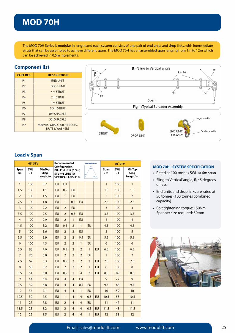
MOD 70H
The MOD 70H Series is modular in length and each system consists of one pair of end units and drop links, with intermediate struts that can be assembled to achieve different spans. The MOD 70H has an assembled span ranging from 1m to 12m which can be achieved in 0.5m increments.
PaRT REF: DESCRIPTION
P1 EnD UnIT
P2 DROP LInK
P3 4m STRUT
P4 2m STRUT
P5 1m STRUT
P6 0.5m STRUT
P7 85t SHACKLE
P8 55t SHACKLE
P9 M20X65, GRADE 8.8 HT BOLTS, nUTS & WASHERS
Component list
STRUTDROP LInK
EnD UnIT SUB-ASSY
Larger shackle
Smaller shackle
Load v Span
Span /m
SWL/ t
Min Top Sling
Length /m
Span / m
SWL/ t
Min Top Sling
Length / m
1 100 0.7 EU EU 1 100 1
1.5 100 1.1 EU 0.5 EU 1.5 100 1.5
2 100 1.5 EU 1 EU 2 100 2
2.5 100 1.8 EU 1 0.5 EU 2.5 100 2.5
3 100 2.2 EU 2 EU 3 100 3
3.5 100 2.5 EU 2 0.5 EU 3.5 100 3.5
4 100 2.9 EU 2 1 EU 4 100 4
4.5 100 3.2 EU 0.5 2 1 EU 4.5 100 4.5
5 100 3.6 EU 2 2 EU 5 100 5
5.5 100 3.9 EU 2 2 0.5 EU 5.5 100 5.5
6 100 4.3 EU 2 2 1 EU 6 100 6
6.5 88 4.6 EU 0.5 2 2 1 EU 6.5 100 6.5
7 76 5.0 EU 2 2 2 EU 7 100 7
7.5 67 5.3 EU 0.5 2 2 2 EU 7.5 100 7.5
8 58 5.7 EU 2 2 2 1 EU 8 100 8
8.5 51 6.0 EU 0.5 1 4 2 EU 8.5 89 8.5
9 44 6.4 EU 4 4 EU 9 77 9
9.5 39 6.8 EU 4 4 0.5 EU 9.5 68 9.5
10 34 7.1 EU 4 4 1 EU 10 59 10
10.5 30 7.5 EU 1 4 4 0.5 EU 10.5 53 10.5
11 27 7.8 EU 2 4 4 EU 11 47 11
11.5 25 8.2 EU 2 4 4 0.5 EU 11.5 43 11.5
12 22 8.5 EU 2 4 4 1 EU 12 38 12
45˚ STV 30˚ STVRecommendedConfigurationEU - End Unit (0.5m)STV = ‘SLING TO VERTICaL aNGLE, ß
MOD 70H - SySTEM SPECIFICaTION• Ratedat100tonnesSWLat6mspan
• SlingtoVertical’angle,ß,45degrees or less
• Endunitsanddroplinksareratedat 50 tonnes (100 tonnes combined capacity)
• Bolttighteningtorque:150Nm Spanner size required: 30mm
Sling Angle Format
BSA
ISA
STV
25
Fig.1: Typical Spreader Assembly.
P7
P9 P2P1
P3 - P6
P8
b
Fig. 1: Typical Spreader Assembly.
β =’Sling to Vertical’ angle
Span

Email: [email protected] www.modulift.com26
45º STV Recommended Configuration.EU - End Unit (0.5m)STV = ‘SLING TO VERTICaL’ aNGLE, ß
30º STV
Span /m
SWL/ t
Min Top sling
Length / m
Span / m
SWL/ t
Min Top sling
Length / m
1 34 0.7 EU EU 1 34 1
1.5 34 1.1 EU 0.5 EU 1.5 34 1.5
2 34 1.5 EU 1 EU 2 34 2
2.5 34 1.8 EU 1 0.5 EU 2.5 34 2.5
3 34 2.2 EU 2 EU 3 34 3
3.5 34 2.5 EU 2 0.5 EU 3.5 34 3.5
4 34 2.9 EU 2 1 EU 4 34 4
4.5 34 3.2 EU 0.5 2 1 EU 4.5 34 4.5
5 34 3.6 EU 4 EU 5 34 5
5.5 34 3.9 EU 4 0.5 EU 5.5 34 5.5
6 34 4.3 EU 4 1 EU 6 34 6
6.5 34 4.6 EU 0.5 4 1 EU 6.5 34 6.5
7 34 5.0 EU 4 2 EU 7 34 7
7.5 34 5.3 EU 0.5 4 2 EU 7.5 34 7.5
8 34 5.7 EU 1 4 2 EU 8 34 8
8.5 34 6.0 EU 0.5 1 4 2 EU 8.5 34 8.5
9 34 6.4 EU 4 4 EU 9 34 9
9.5 34 6.8 EU 4 4 0.5 EU 9.5 34 9.5
10 34 7.1 EU 4 4 1 EU 10 34 10
10.5 30 7.5 EU 1 4 4 0.5 EU 10.5 34 10.5
11 27 7.8 EU 2 4 4 EU 11 34 11
11.5 25 8.2 EU 2 4 4 0.5 EU 11.5 34 11.5
12 22 8.5 EU 2 4 4 1 EU 12 34 12
The Modulift Spreader is modular in length. Every spreader consists of 1 pair of End Units & Drop Links, with intermediate struts that can be assembled to achieve different spans. The Modulift 70/34 has an assembled span ranging from 1 metre to 12 metres in 0.5 metre increments.
Component listPaRT REF: DESCRIPTION
P1 EnD UnIT (STEP DOWn)
P2 DROP LInK (MOD 34)
P3 4.0m STRUT
P4 2.0m STRUT
P5 1.0m STRUT
P6 0.5m STRUT
P7 25t SHACKLE
P8 17t SHACKLE
P9 M20x65 HT BOLTS,nUTS & WASHERS
Load v Span
MOD 70/34 - SySTEM SPECIFICaTION• Ratedat34tonnesSWLat10m span
• ‘SlingtoVertical’angle,ß,45degrees or less
• Endunitsanddroplinksareratedat 17 tonnes (34 tonnes combined capacity)
• Bolttighteningtorque:150Nm Spanner size required: 30mm
MOD 70/34: Step-Downs
Sling Angle Format
BSA
ISA
STV
DROP LInKEnD UnIT SUB-ASSY
Larger shackle
Smaller shackleSTEP DOWn STRUT
ß =’Sling to Vertical’ angle
Fig.1: Typical Spreader Assembly.
b
Span
P3 - P6P7
P2P9
P1P8

Email: [email protected] www.modulift.com
45º STV Recommended Configuration.EU - End Unit (0.5m)STV = ‘SLING TO VERTICaL’ aNGLE, ß
30º STV
Span /m
SWL/ t
Min Top sling
Length / m
Span / m
SWL/ t
Min Top sling
Length / m
1 24 0.7 EU EU 1 24 1
1.5 24 1.1 EU 0.5 EU 1.5 24 1.5
2 24 1.5 EU 1 EU 2 24 2
2.5 24 1.8 EU 1 0.5 EU 2.5 24 2.5
3 24 2.2 EU 2 EU 3 24 3
3.5 24 2.5 EU 2 0.5 EU 3.5 24 3.5
4 24 2.9 EU 2 1 EU 4 24 4
4.5 24 3.2 EU 0.5 2 1 EU 4.5 24 4.5
5 24 3.6 EU 4 EU 5 24 5
5.5 24 3.9 EU 4 0.5 EU 5.5 24 5.5
6 24 4.3 EU 4 1 EU 6 24 6
6.5 24 4.6 EU 0.5 4 1 EU 6.5 24 6.5
7 24 5.0 EU 4 2 EU 7 24 7
7.5 24 5.3 EU 0.5 4 2 EU 7.5 24 7.5
8 24 5.7 EU 1 4 2 EU 8 24 8
8.5 24 6.0 EU 0.5 1 4 2 EU 8.5 24 8.5
9 24 6.4 EU 4 4 EU 9 24 9
9.5 24 6.8 EU 4 4 0.5 EU 9.5 24 9.5
10 24 7.1 EU 4 4 1 EU 10 24 10
10.5 24 7.5 EU 1 4 4 0.5 EU 10.5 24 10.5
11 24 7.8 EU 2 4 4 EU 11 24 11
11.5 24 8.2 EU 2 4 4 0.5 EU 11.5 24 11.5
12 22 8.5 EU 2 4 4 1 EU 12 24 12
The Modulift Spreader is modular in length. Every spreader consists of 1 pair of End Units & Drop Links, with intermediate struts that can be assembled to achieve different spans. The Modulift 70/24 has an assembled span ranging from 1 metre to 12 metres in 0.5 metre increments.
Component listPaRT REF: DESCRIPTION
P1 EnD UnIT (STEP DOWn)
P2 DROP LInK (MOD 24)
P3 4.0m STRUT
P4 2.0m STRUT
P5 1.0m STRUT
P6 0.5m STRUT
P7 17t SHACKLE
P8 12t SHACKLE
P9 M20x65 HT BOLTS,nUTS & WASHERS
Load v Span
MOD 70/34 - SySTEM SPECIFICaTION• Ratedat24tonnesSWLat11.5m span
• ‘SlingtoVertical’angle,ß,45degrees or less
• Endunitsanddroplinksareratedat 12 tonnes (24 tonnes combined capacity)
• Bolttighteningtorque:150Nm Spanner size required: 30mm
MOD 70/24: Step-Downs
Sling Angle Format
BSA
ISA
STV
DROP LInKEnD UnIT SUB-ASSY
Larger shackle
Smaller shackleSTEP DOWn STRUT
27
ß =’Sling to Vertical’ angle
Fig.1: Typical Spreader Assembly.
b
Span
P3 - P6 P7
P2P9
P1P8

Email: [email protected] www.modulift.com28
MOD 110
The MOD 110 Series is modular in length and each system consists of one pair of end units and drop links, with intermediate struts that can be assembled to achieve different spans. The MOD 110 has an assembled span ranging from 2m to 16m which can be achieved in 0.5m increments.
PaRT REF: DESCRIPTION
P1 EnD UnIT
P2 DROP LInK
P3 4m STRUT
P4 2m STRUT
P5 1m STRUT
P6 0.5 STRUT
P7 85t SHACKLE
P8 55t SHACKLE
P9 M20X65 HT BOLTS, nUTS & WASHERS
Component list
STRUT DROP LInKEnD UnIT SUB-ASSY
Larger shackle
Smaller shackle
Load v Span
Span /m
SWL/ t
Min Top sling
Length / m
Span / m
SWL/ t
Min Top Sling
Length / m
2 110 1.5 EU EU 2 110 2
2.5 110 1.8 EU 0.5 EU 2.5 110 2.5
3 110 2.2 EU 1 EU 3 110 3
3.5 110 2.5 EU 1 0.5 EU 3.5 110 3.5
4 110 2.9 EU 2 EU 4 110 4
4.5 110 3.2 EU 2 0.5 EU 4.5 110 4.5
5 110 3.6 EU 2 1 EU 5 110 5
5.5 110 3.9 EU 0.5 2 1 EU 5.5 110 5.5
6 110 4.3 EU 2 2 EU 6 110 6
6.5 109 4.6 EU 2 2 0.5 EU 6.5 110 6.5
7 106 5.0 EU 2 2 1 EU 7 110 7
7.5 102 5.3 EU 0.5 2 2 1 EU 7.5 110 7.5
8 98 5.7 EU 2 2 2 EU 8 110 8
8.5 93 6.0 EU 0.5 2 2 2 EU 8.5 110 8.5
9 88 6.4 EU 2 2 2 1 EU 9 110 9
9.5 83 6.8 EU 0.5 1 4 2 EU 9.5 110 9.5
10 78 7.1 EU 4 4 EU 10 110 10
10.5 72 7.5 EU 4 4 0.5 EU 10.5 110 10.5
11 66 7.8 EU 4 4 1 EU 11 110 11
11.5 62 8.2 EU 0.5 4 4 1 EU 11.5 107 11.5
12 58 8.5 EU 2 4 4 EU 12 100 12
12.5 53 9.0 EU 2 4 4 0.5 EU 12.5 92 12.5
13 48 9.5 EU 2 4 4 1 EU 13 84 13
13.5 45 9.75 EU 2 4 4 1 0.5 EU 13.5 80 13.5
14 43 10.0 EU 4 4 4 EU 14 75 14
14.5 39 10.25 EU 0.5 4 4 4 EU 14.5 69 14.5
15 35 10.5 EU 4 4 4 1 EU 15 62 15
15.5 33 11.0 EU 0.5 4 4 4 1 EU 15.5 58 15.5
16 31 11.5 EU 4 4 4 2 EU 16 53 16
45˚ STV 30˚ STVRecommendedConfigurationEU - End Unit (1m)STV = ‘SLING TO VERTICaL’aNGLE , ß
MOD 110 - SySTEM SPECIFICaTION• Ratedat110tonnesSWLat6mspan.
• ‘SlingtoVertical’angle,ß,45degrees or less
• Endunitsanddroplinksareratedat55 tonnes 110 tonnes combined capacity)
• Bolttighteningtorque:150Nm Spanner size required: 30mm
Sling Angle Format
BSA
ISA
STV
Fig.1: Typical Spreader Assembly.
P7
P9 P2P1
P3 - P6
P8
b
β =’Sling to Vertical’ angle
Span
Fig. 1: Typical Spreader Assembly.

Email: [email protected] www.modulift.com
MOD 110H
The MOD 110H Series is modular in length and each system consists of one pair of end units and drop links, with intermediate struts that can be assembled to achieve different spans. The MOD 110H has an assembled span ranging from 2m to 16m which can be achieved in 0.5m increments.
Component list
MOD 110H - SySTEM SPECIFICaTION• Ratedat170tonnesSWLat8mspan
• ‘SlingtoVertical’angle,ß,45degrees or less
• Endunitsanddroplinksareratedat85 tonnes (170 tons combined capacity)
• Bolttighteningtorque:150Nm Spanner size required: 30mm
Load v Span
Span / m
SWL/ t
Min Top Sling
Length/ m
Span / m
SWL/ t
Min Top Sling
Length / m
2 125 1.5 EU EU 2 170 2
2.5 124 1.8 EU 0.5 EU 2.5 170 2.5
3 124 2.2 EU 1 EU 3 170 3
3.5 123 2.5 EU 1 0.5 EU 3.5 170 3.5
4 122 2.9 EU 2 EU 4 170 4
4.5 120 3.2 EU 2 0.5 EU 4.5 170 4.5
5 118 3.6 EU 2 1 EU 5 170 5
5.5 115 3.9 EU 0.5 2 1 EU 5.5 170 5.5
6 112 4.3 EU 2 2 EU 6 170 6
6.5 109 4.6 EU 2 2 0.5 EU 6.5 170 6.5
7 106 5.0 EU 2 2 1 EU 7 170 7
7.5 102 5.3 EU 0.5 2 2 1 EU 7.5 170 7.5
8 98 5.7 EU 2 2 2 EU 8 170 8
8.5 93 6.0 EU 0.5 2 2 2 EU 8.5 161 8.5
9 88 6.4 EU 2 2 2 1 EU 9 152 9
9.5 83 6.8 EU 0.5 1 4 2 EU 9.5 144 9.5
10 78 7.1 EU 4 4 EU 10 135 10
10.5 72 7.5 EU 4 4 0.5 EU 10.5 125 10.5
11 66 7.8 EU 4 4 1 EU 11 114 11
11.5 62 8.2 EU 0.5 4 4 1 EU 11.5 107 11.5
12 58 8.5 EU 2 4 4 EU 12 100 12
12.5 53 9.0 EU 2 4 4 0.5 EU 12.5 92 12.5
13 48 9.5 EU 2 4 4 1 EU 13 84 13
13.5 45 9.75 EU 2 4 4 1 0.5 EU 13.5 80 13.5
14 43 10.0 EU 4 4 4 EU 14 75 14
14.5 39 10.25 EU 0.5 4 4 4 EU 14.5 69 14.5
15 35 10.5 EU 4 4 4 1 EU 15 62 15
15.5 33 11.0 EU 0.5 4 4 4 1 EU 15.5 58 15.5
16 31 11.5 EU 4 4 4 2 EU 16 53 16
45˚ STV 30˚ STVRecommendedConfigurationEU - End Unit (1m)STV = ‘SLING TO VERTICaL’ aNGLE, ß
PaRT REF: DESCRIPTION
P1 EnD UnIT
P2 DROP LInK
P3 4m STRUT
P4 2m STRUT
P5 1m STRUT
P6 0.5m STRUT
P7 120t SHACKLE
P8 85t SHACKLE
P9 M20X65 HT BOLTS, nUTS & WASHERS
STRUTDROP LInK
EnD UnIT SUB-ASSY
Larger shackle
Smaller shackle
Sling Angle Format
BSA
ISA
STV
29
Fig.1: Typical Spreader Assembly.
P7
P9 P2P1
P3 - P6
P8
b
β =’Sling to Vertical’ angle
Span
Fig. 1: Typical Spreader Assembly.

Email: [email protected] www.modulift.com30
MOD 110SH
The Modulift Spreader is modular in length. Every spreader consists of 1 pair of End Units & Drop Links, with intermediate struts that can be bolted into the assembly to achieve different spans. The MOD 110SH has an assembled span ranging from 2m to 16m in 0.5m increments.
Component list
PaRT REF: DESCRIPTION
P1 EnD UnIT
P2 DROP LInK
P3 4m STRUT
P4 2m STRUT
P5 1m STRUT
P6 0.5m STRUT
P7 150t SHACKLE
P8 120t SHACKLE
P9 M20X65 GRADE 8.8, HT BOLTS, nUTS & WASHERS
Load v Span
Span /m
SWL/ t
Min Top sling
Length/ m
Span / m
SWL/ t
Min Top sling
Length/ m
2 158 1.5 EU EU 2 240 2
2.5 157 1.8 EU 0.5 EU 2.5 240 2.5
3 156 2.2 EU 1 EU 3 240 3
3.5 154 2.5 EU 1 0.5 EU 3.5 240 3.5
4 152 2.9 EU 2 EU 4 240 4
4.5 149 3.2 EU 2 0.5 EU 4.5 240 4.5
5 146 3.6 EU 2 1 EU 5 240 5
5.5 143 3.9 EU 0.5 2 1 EU 5.5 240 5.5
6 140 4.3 EU 2 2 EU 6 240 6
6.5 136 4.6 EU 2 2 0.5 EU 6.5 234 6.5
7 132 5.0 EU 2 2 1 EU 7 228 7
7.5 126 5.3 EU 0.5 2 2 1 EU 7.5 219 7.5
8 121 5.7 EU 2 2 2 EU 8 210 8
8.5 115 6.0 EU 0.5 2 2 2 EU 8.5 200 8.5
9 110 6.4 EU 2 2 2 1 EU 9 190 9
9.5 103 6.8 EU 0.5 1 4 2 EU 9.5 180 9.5
10 96 7.1 EU 4 4 EU 10 170 10
10.5 89 7.5 EU 4 4 0.5 EU 10.5 156 10.5
11 82 7.8 EU 4 4 1 EU 11 142 11
11.5 75 8.2 EU 1 4 4 0.5 EU 11.5 133 11.5
12 72 8.5 EU 2 4 4 EU 12 125 12
12.5 66 9.0 EU 2 4 4 0.5 EU 12.5 114 12.5
13 60 9.5 EU 2 4 4 1 EU 13 104 13
13.5 57 9.75 EU 2 4 4 1 0.5 EU 13.5 98 13.5
14 53 10.0 EU 4 4 4 EU 14 92 14
14.5 48 10.25 EU 0.5 4 4 4 EU 14.5 84 14.5
15 44 10.5 EU 4 4 4 1 EU 15 76 15
15.5 41 11.0 EU 0.5 4 4 4 1 EU 15.5 71 15.5
16 38 11.5 EU 4 4 4 2 EU 16 66 16
45˚ STV 30˚ STVRecommendedConfigurationEU - End Unit (1m)STV = ‘SLING TO VERTICaL’ aNGLE, ß
MOD 110SH - SySTEM SPECIFICaTION• Ratedat240tonnesSWLat6mspan
• ‘SlingtoVertical’angle,ß,45degrees or less
• Endunitsanddroplinksareratedat 120 tonnes (240 tonnes combined capacity)
• Bolttighteningtorque:150Nm Spanner size required: 30mm
STRUT DROP LInKEnD UnIT SUB-ASSY
Larger shackle
Smaller shackle
Sling Angle Format
BSA
ISA
STV
Fig.1: Typical Spreader Assembly.
P7
P9 P2P1
P3 - P6
P8
b
β =’Sling to Vertical’ angle
Span
Fig. 1: Typical Spreader Assembly.

Email: [email protected] www.modulift.com
45º STV Recommended Configuration.EU - End Unit (0.5m)STV = ‘SLING TO VERTICaL’ aNGLE, ß
30º STVSpan
/mSWL
/ tMin Top
slingLength / m
Span / m
SWL/ t
Min Top sling
Length / m
2 70 1.5 EU EU 2 70 2
2.5 70 2.0 EU 0.5 EU 2.5 70 2.5
3 70 2.5 EU 1 EU 3 70 3
3.5 70 2.8 EU 1 0.5 EU 3.5 70 3.5
4 70 3.0 EU 2 EU 4 70 4
4.5 70 3.3 EU 2 1 EU 4.5 70 4.5
5 70 3.5 EU 2 1 EU 5 70 5
5.5 70 4.0 EU 0.5 2 1 EU 5.5 70 5.5
6 70 4.5 EU 4 EU 6 70 6
6.5 70 4.8 EU 2 2 0.5 EU 6.5 70 6.5
7 70 5.0 EU 4 1 EU 7 70 7
7.5 70 5.5 EU 0.5 2 2 1 EU 7.5 70 7.5
8 70 6.0 EU 4 2 EU 8 70 8
8.5 70 6.5 EU 0.5 2 2 2 EU 8.5 70 8.5
9 70 6.5 EU 4 2 1 EU 9 70 9
9.5 70 6.8 EU 0.5 1 4 2 EU 9.5 70 9.5
10 70 7.0 EU 4 4 EU 10 70 10
10.5 70 7.5 EU 4 4 0.5 EU 10.5 70 10.5
11 66 8.0 EU 4 4 1 EU 11 70 11
11.5 62 8.3 EU 1 4 1 0.5 EU 11.5 70 11.5
12 58 8.5 EU 4 4 2 EU 12 70 12
12.5 53 9.0 EU 2 4 4 0.5 EU 12.5 70 12.5
13 48 9.5 EU 1 4 4 2 EU 13 70 13
13.5 45 9.8 EU 2 4 4 1 0.5 EU 13.5 70 13.5
14 43 10.0 EU 4 4 4 EU 14 70 14
14.5 39 10.3 EU 0.5 4 4 4 EU 14.5 67 14.5
15 35 10.5 EU 4 4 4 1 EU 15 62 15
15.5 33 11.0 EU 0.5 4 4 4 1 EU 15.5 58 15.5
16 31 11.5 EU 4 4 4 2 EU 16 53 16
The Modulift Spreader is modular in length. Every spreader consists of 1 pair of End Units & Drop Links, with intermediate struts that can be assembled to achieve different spans. The Modulift 110/70 has an assembled span ranging from 1 metre to 16 metres in 0.5 metre increments.
Component listPaRT REF: DESCRIPTION
P1 EnD UnIT (STEP DOWn)
P2 DROP LInK (MOD 70)
P3 4.0m STRUT
P4 2.0m STRUT
P5 1.0m STRUT
P6 0.5m STRUT
P7 55t SHACKLE
P8 35t SHACKLE
P9 M20x65 HT BOLTS,nUTS & WASHERS
Load v Span
MOD 110/70 - SySTEM SPECIFICaTION• Ratedat70tonnesSWLat10m span
• ‘SlingtoVertical’angle,ß,45degrees or less
• Endunitsanddroplinksareratedat 35 tonnes (70 tonnes combined capacity)
• Bolttighteningtorque:150Nm Spanner size required: 30mm
MOD 110/70: Step-Downs
STRUTDROP LInK
EnD UnIT SUB-ASSY
Larger shackle
Smaller shackle
Sling Angle Format
BSA
ISA
STV
STEP DOWn
31
ß =’Sling to Vertical’ angle
Fig.1: Typical Spreader Assembly.
b
Span
P3 - P6P7
P2P9
P1P8

Email: [email protected] www.modulift.com32
The Modulift Spreader is modular in length. Every spreader consists of 1 pair of End Units & Drop Links, with intermediate struts that can be assembled to achieve different spans. The Modulift 110/50 has an assembled span ranging from 1 metre to 16 metres in 0.5 metre increments.
Component listPaRT REF: DESCRIPTION
P1 EnD UnIT (STEP DOWn)
P2 DROP LInK (MOD 50)
P3 4.0m STRUT
P4 2.0m STRUT
P5 1.0m STRUT
P6 0.5m STRUT
P7 35t SHACKLE
P8 25t SHACKLE
P9 M20x65 HT BOLTS,nUTS & WASHERS
Load v Span
MOD 110/50 - SySTEM SPECIFICaTION• Ratedat50tonnesSWLat16m span
• ‘SlingtoVertical’angle,ß,45degrees or less
• Endunitsanddroplinksareratedat 25 tonnes (50 tonnes combined capacity)
• Bolttighteningtorque:150Nm Spanner size required: 30mm
MOD 110/50: Step-Downs
STRUTDROP LInK
EnD UnIT SUB-ASSY
Larger shackle
Smaller shackleSTEP DOWn
Span /m
SWL/ t
Min Top sling
Length / m
Span / m
SWL/ t
Min Top Sling
Length / m
2 110 1.5 EU EU 2 110 2
2.5 110 1.8 EU 0.5 EU 2.5 110 2.5
3 110 2.2 EU 1 EU 3 110 3
3.5 110 2.5 EU 1 0.5 EU 3.5 110 3.5
4 110 2.9 EU 2 EU 4 110 4
4.5 110 3.2 EU 2 0.5 EU 4.5 110 4.5
5 110 3.6 EU 2 1 EU 5 110 5
5.5 110 3.9 EU 0.5 2 1 EU 5.5 110 5.5
6 110 4.3 EU 2 2 EU 6 110 6
6.5 109 4.6 EU 2 2 0.5 EU 6.5 110 6.5
7 106 5.0 EU 2 2 1 EU 7 110 7
7.5 102 5.3 EU 0.5 2 2 1 EU 7.5 110 7.5
8 98 5.7 EU 2 2 2 EU 8 110 8
8.5 93 6.0 EU 0.5 2 2 2 EU 8.5 110 8.5
9 88 6.4 EU 2 2 2 1 EU 9 110 9
9.5 83 6.8 EU 0.5 1 4 2 EU 9.5 110 9.5
10 78 7.1 EU 4 4 EU 10 110 10
10.5 72 7.5 EU 4 4 0.5 EU 10.5 110 10.5
11 66 7.8 EU 4 4 1 EU 11 110 11
11.5 62 8.2 EU 0.5 4 4 1 EU 11.5 107 11.5
12 58 8.5 EU 2 4 4 EU 12 100 12
12.5 53 9.0 EU 2 4 4 0.5 EU 12.5 92 12.5
13 48 9.5 EU 2 4 4 1 EU 13 84 13
13.5 45 9.75 EU 2 4 4 1 0.5 EU 13.5 80 13.5
14 43 10.0 EU 4 4 4 EU 14 75 14
14.5 39 10.25 EU 0.5 4 4 4 EU 14.5 69 14.5
15 35 10.5 EU 4 4 4 1 EU 15 62 15
15.5 33 11.0 EU 0.5 4 4 4 1 EU 15.5 58 15.5
16 31 11.5 EU 4 4 4 2 EU 16 53 16
45˚ STV 30˚ STVRecommendedConfigurationEU - End Unit (1m)STV = ‘SLING TO VERTICaL’aNGLE , ß
Sling Angle Format
BSA
ISA
STV
ß =’Sling to Vertical’ angle
Fig.1: Typical Spreader Assembly.
b
Span
P3 - P6 P7
P2P9
P1P8

Email: [email protected] www.modulift.com
P9
MOD 250/250
The Modulift Spreader is modular in length. Every spreader consists of 1 pair of End Units & Drop Links, with intermediate struts that can be bolted into the assembly to achieve different spans. The MOD 250/250 has an assembled span ranging from 2 metres to 20m in 1m increments.
Component listPaRT REF: DESCRIPTION
P1 EnD UnIT WLL 125t
P2 DROP LInK WLL 125t
P3 6m STRUT
P4 3m STRUT
P5 2m STRUT
P6 1m STRUT
P7 0.5m STRUT
P8 200t WIDE BODY SHACKLE
P9 125t WIDE BODY SHACKLE
P10 M24X80 GRADE 8.8, HT BOLTS, nUTS & WASHERS STRUT DROP LInK
EnD UnIT SUB-ASSY
Larger shackle
Smaller shackle
Span /m
SWL/ t
Min Top sling
Length / m
Span / m
SWL/ t
Min Top sling
Length / m
2 250 1.5 EU EU 2 250 2
3 250 2.5 EU 1 EU 3 250 3
4 250 3.0 EU 2 EU 4 250 4
5 250 3.5 EU 3 EU 5 250 5
6 250 4.5 EU 3 1 EU 6 250 6
7 250 5.0 EU 3 2 EU 7 250 7
8 244 6.0 EU 6 EU 8 250 8
9 228 6.5 EU 6 1 EU 9 250 9
10 212 7.0 EU 6 2 EU 10 250 10
11 194 8.0 EU 6 3 EU 11 250 11
12 178 8.5 EU 3 6 1 EU 12 250 12
13 158 9.5 EU 3 6 2 EU 13 250 13
14 140 10.0 EU 6 6 EU 14 242 14
15 122 10.5 EU 6 6 1 EU 15 211 15
16 106 11.5 EU 6 6 2 EU 16 183 16
17 94 12.0 EU 6 6 3 EU 17 163 17
18 82 13.0 EU 1 6 6 3 EU 18 142 18
19 70 13.5 EU 2 6 6 3 EU 19 121 19
20 52 14.5 EU 2 6 6 3 1 EU 20 90 20
45˚ STV 30˚ STVRecommendedConfigurationEU - End Unit (1m)STV = ‘SLING TO VERTICaL’ aNGLE, ß
Load v Span
MOD 250/250 - SySTEM SPECIFICaTION• Ratedat250tonnesSWLat13mspan
• ‘SlingtoVertical’angle,ß,45degrees or less
• Endunitsanddroplinksareratedat 125 tonnes (250 tonnes combined capacity)
• Bolttighteningtorque:250Nm Spanner size required: 36mm
Sling Angle Format
BSA
ISA
STV
33
Fig. 1: Typical Spreader Assembly.
P9P1
P10
P8
P2
P3 - P7b
Span
ß =’Sling to Vertical’ angle

Email: [email protected] www.modulift.com34
P9
MOD 250/300
The Modulift Spreader is modular in length. Every spreader consists of 1 pair of End Units & Drop Links, with intermediate struts that can be bolted into the assembly to achieve different spans. The MOD 250/300 has an assembled span ranging from 2 metres to 20m in 1m increments.
Component listPaRT REF: DESCRIPTION
P1 EnD UnIT WLL 150t
P2 DROP LInK WLL 150t
P3 6m STRUT
P4 3m STRUT
P5 2m STRUT
P6 1m STRUT
P7 0.5m STRUT
P8 200t WIDE BODY SHACKLE
P9 150t WIDE BODY SHACKLE
P10 M24X80 GRADE 8.8, HT BOLTS, nUTS & WASHERS
Span /m
SWL/ t
Min Top sling
Length / m
Span / m
SWL/ t
Min Top sling
Length / m
2 278 1.5 EU EU 2 300 2
3 278 2.5 EU 1 EU 3 300 3
4 278 3.0 EU 2 EU 4 300 4
5 272 3.5 EU 3 EU 5 300 5
6 264 4.5 EU 3 1 EU 6 300 6
7 254 5.0 EU 3 2 EU 7 300 7
8 244 6.0 EU 6 EU 8 300 8
9 228 6.5 EU 6 1 EU 9 300 9
10 212 7.0 EU 6 2 EU 10 300 10
11 194 8.0 EU 6 3 EU 11 300 11
12 178 8.5 EU 3 6 1 EU 12 300 12
13 158 9.5 EU 3 6 2 EU 13 273 13
14 140 10.0 EU 6 6 EU 14 242 14
15 122 10.5 EU 6 6 1 EU 15 211 15
16 106 11.5 EU 6 6 2 EU 16 183 16
17 94 12.0 EU 6 6 3 EU 17 163 17
18 82 13.0 EU 1 6 6 3 EU 18 142 18
19 70 13.5 EU 2 6 6 3 EU 19 121 19
20 52 14.5 EU 3 6 6 2 1 EU 20 90 20
45˚ STV 30˚ STVRecommendedConfigurationEU - End Unit (1m)STV = ‘SLING TO VERTICaL’ aNGLE, ß
Load v Span
MOD 250/300 - SySTEM SPECIFICaTION• Ratedat300tonnesSWLat12m span
• ‘SlingtoVertical’angle,ß,45degrees or less
• Endunitsanddroplinksareratedat 150 tonnes (300 tonnes combined capacity)
• Bolttighteningtorque:250Nm Spanner size required: 36mm
STRUTDROP LInK
EnD UnIT SUB-ASSY
Larger shackle
Smaller shackle
Sling Angle Format
BSA
ISA
STV
Fig. 1: Typical Spreader Assembly.
P9P1 P10
P8
P2
P3 - P7
β =’Sling to Vertical’ angle
b
Span

Email: [email protected] www.modulift.com
P9
MOD 250/400
The Modulift Spreader is modular in length. Every spreader consists of 1 pair of End Units & Drop Links, with intermediate struts that can be bolted into the assembly to achieve different spans. The MOD 250/400 has an assembled span ranging from 2 metres to 20m in 1m increments.
Component list
PaRT REF: DESCRIPTION
P1 EnD UnIT WLL 200t
P2 DROP LInK WLL 200t
P3 6m STRUT
P4 3m STRUT
P5 2m STRUT
P6 1m STRUT
P7 0.5m STRUT
P8 300t WIDE BODY SHACKLE
P9 200t WIDE BODY SHACKLE
P10 M24X80 GRADE 8.8, HT BOLTS, nUTS & WASHERS
Span /m
SWL/ t
Min Top sling
Length / m
Span / m
SWL/ t
Min Top sling
Length / m
2 300 1.5 EU EU 2 400 2
3 284 2.5 EU 1 EU 3 400 3
4 278 3.0 EU 2 EU 4 400 4
5 272 3.5 EU 3 EU 5 400 5
6 264 4.5 EU 3 1 EU 6 400 6
7 254 5.0 EU 3 2 EU 7 400 7
8 244 6.0 EU 6 EU 8 400 8
9 228 6.5 EU 6 1 EU 9 394 9
10 212 7.0 EU 6 2 EU 10 367 10
11 194 8.0 EU 6 3 EU 11 336 11
12 178 8.5 EU 3 6 1 EU 12 308 12
13 158 9.5 EU 3 6 2 EU 13 273 13
14 140 10.0 EU 6 6 EU 14 242 14
15 122 10.5 EU 6 6 1 EU 15 211 15
16 106 11.5 EU 6 6 2 EU 16 183 16
17 94 12.0 EU 6 6 3 EU 17 163 17
18 82 13.0 EU 1 6 6 3 EU 18 142 18
19 70 13.5 EU 2 6 6 3 EU 19 121 19
20 52 14.5 EU 3 6 6 2 1 EU 20 90 20
45˚ STV 30˚ STVRecommendedConfigurationEU - End Unit (1m)STV = ‘SLING TO VERTICaL’ aNGLE, ß
Load v Span
MOD 250/400 - SySTEM SPECIFICaTION• Ratedat400tonnesSWLat8mspan
• ‘SlingtoVertical’angle,ß,45degrees or less
• Endunitsanddroplinksareratedat 200 tonnes (400 tonnes combined capacity)
• Bolttighteningtorque:250Nm Spanner size required: 36mm
STRUT DROP LInKEnD UnIT SUB-ASSY
Larger shackle
Smaller shackle
Sling Angle Format
BSA
ISA
STV
35
Fig. 1: Typical Spreader Assembly.
P9P1
P10
P8
P2
P3 - P7
β =’Sling to Vertical’ angle
b
Span

Email: [email protected] www.modulift.com36
45º STV Recommended Configuration.EU - End Unit (1m)Ca - Cone adaptor (0.5m)
30º STVSpan
/mSWL
/ tMin Top
slingLength / m
Span / m
SWL/ t
Min Top sling
Length / m
2 170 1.5 EU EU 2 170 2
3 170 2.5 EU CA CA EU 3 170 3
4 170 3.0 EU CA 1 CA EU 4 170 4
5 170 3.5 EU CA 2 CA EU 5 170 5
6 170 4.5 EU CA 3 CA EU 6 170 6
7 170 5.0 EU CA 3 1 CA EU 7 170 7
8 170 6.0 EU CA 3 2 CA EU 8 170 8
9 170 6.5 EU CA 6 CA EU 9 170 9
10 170 7.0 EU CA 6 1 CA EU 10 170 10
11 170 8.0 EU CA 6 2 CA EU 11 170 11
12 170 8.5 EU CA 6 3 CA EU 12 170 12
13 158 9.5 EU CA 3 6 1 CA EU 13 170 13
14 140 10.0 EU CA 3 6 2 CA EU 14 170 14
15 122 10.5 EU CA 6 6 CA EU 15 170 15
16 106 11.5 EU CA 6 6 1 CA EU 16 170 16
17 94 12.0 EU CA 6 6 2 CA EU 17 163 17
18 82 13.0 EU CA 6 6 3 CA EU 18 142 18
19 70 13.5 EU CA 1 6 6 3 CA EU 19 121 19
20 52 14.5 EU CA 2 6 6 3 CA EU 20 90 20
The Modulift Spreader is modular in length. Every spreader consists of 1 pair of End Units & Drop Links, with intermediate struts that can be assembled to achieve different spans. The Modulift 250/110H has an assembled span ranging from 2 metres to 20 metres in 1 metre increments.
Component listPaRT REF: DESCRIPTION
P1 EnD UnIT - MOD 110H WLL 85t
P2 DROP LInK - MOD 110H WLL 85t
P3 6.0m STRUT
P4 3.0m STRUT
P5 2.0m STRUT
P6 1.0m STRUT
P7 0.5 STRUT
P8 MOD 250/110 COnE ADAPTER
P9 120t SHACKLE
P10 85t SHACKLE
P11 MOD 250: M24x80 HT BOLTS, NUTS & WASHERS
MOD 110H: M20x65 HT BOLTS, NUTS & WASHERS
Load v Span
MOD 250/110H - SySTEM SPECIFICaTION• Ratedat170tonnesSWLat16m span
• ‘SlingtoVertical’angle,ß,45degrees or less
• Endunitsanddroplinksareratedat 85 tonnes (170 tonnes combined capacity)
• Bolttighteningtorque:250Nm(M24) 150nm (M20) Spanner size required: 36mm (M24) 30mm (M20)
MOD 250/110H: Hybrid
Sling Angle Format
BSA
ISA
STV
STRUT DROP LInKCOnE ADAPTEREnD UnIT SUB-ASSY
Larger shackle
Smaller shackle
Fig.1: Typical Spreader Assembly.
P1P3 - P7
P2P10
P9P8
b
β =’Sling to Vertical’ angle
Span

Email: [email protected] www.modulift.com
45º STV Recommended Configuration.EU - End Unit (1m)Ca - Cone adaptor (0.5m)
30º STVSpan
/mSWL
/ tMin Top
slingLength / m
Span / m
SWL/ t
Min Top sling
Length / m
2 110 1.5 EU EU 2 110 2
3 110 2.5 EU CA CA EU 3 110 3
4 110 3.0 EU CA 1 CA EU 4 110 4
5 110 3.5 EU CA 2 CA EU 5 110 5
6 110 4.5 EU CA 3 CA EU 6 110 6
7 110 5.0 EU CA 3 1 CA EU 7 110 7
8 110 6.0 EU CA 3 2 CA EU 8 110 8
9 110 6.5 EU CA 6 CA EU 9 110 9
10 110 7.0 EU CA 6 1 CA EU 10 110 10
11 110 8.0 EU CA 6 2 CA EU 11 110 11
12 110 8.5 EU CA 6 3 CA EU 12 110 12
13 110 9.5 EU CA 3 6 1 CA EU 13 110 13
14 110 10.0 EU CA 3 6 2 CA EU 14 110 14
15 110 10.5 EU CA 6 6 CA EU 15 110 15
16 106 11.5 EU CA 6 6 1 CA EU 16 110 16
17 94 12.0 EU CA 6 6 2 CA EU 17 110 17
18 82 13.0 EU CA 6 6 3 CA EU 18 110 18
19 70 13.5 EU CA 1 6 6 3 CA EU 19 110 19
20 52 14.5 EU CA 2 6 6 3 CA EU 20 90 20
The Modulift Spreader is modular in length. Every spreader consists of 1 pair of End Units & Drop Links, with intermediate struts that can be assembled to achieve different spans. The Modulift 250/110 has an assembled span ranging from 2 metres to 20 metres in 1 metre increments.
Component listPaRT REF: DESCRIPTION
P1 EnD UnIT - MOD 110 WLL 55t
P2 DROP LInK - MOD 110 WLL 55t
P3 6.0m STRUT
P4 3.0m STRUT
P5 2.0m STRUT
P6 1.0m STRUT
P7 MOD 250/110 COnE ADAPTER
P8 85t SHACKLE
P9 55t SHACKLE
P10 MOD 250: M24x80 HT BOLTS, NUTS & WASHERS
MOD 110: M20x65 HT BOLTS, NUTS & WASHERS
Load v Span
MOD 250/110 - SySTEM SPECIFICaTION• Ratedat110tonnesSWLat15m span
• ‘SlingtoVertical’angle,ß,45degrees or less
• Endunitsanddroplinksareratedat 55 tonnes (110 tonnes combined capacity)
• Bolttighteningtorque:250Nm(M24) 150nm (M20) Spanner size required: 36mm (M24) 30mm (M20)
MOD 250/110: Hybrid
Sling Angle Format
BSA
ISA
STV
STRUT DROP LInKCOnE ADAPTER EnD UnIT SUB-ASSY
Larger shackle
Smaller shackle
37
Fig.1: Typical Spreader Assembly.
P1P3 - P7
P2P10
P9P8
b
β =’Sling to Vertical’ angle
Span

Email: [email protected] www.modulift.com38
45º STV Recommended Configuration.EU - End Unit (1m)Ca - Cone adaptor (0.5m)
30º STVSpan
/mSWL
/ tMin Top
slingLength / m
Span / m
SWL/ t
Min Top sling
Length / m
1 100 0.8 EU EU 1 100 1
2 100 1.5 EU CA CA EU 2 100 2
3 100 2.5 EU CA 1 CA EU 3 100 3
4 100 3.0 EU CA 2 CA EU 4 100 4
5 100 3.5 EU CA 3 CA EU 5 100 5
6 100 4.5 EU CA 3 1 CA EU 6 100 6
7 100 5.0 EU CA 3 2 CA EU 7 100 7
8 100 6.0 EU CA 6 CA EU 8 100 8
9 100 6.5 EU CA 6 1 CA EU 9 100 9
10 100 7.0 EU CA 6 2 CA EU 10 100 10
11 100 8.0 EU CA 6 3 CA EU 11 100 11
12 100 8.5 EU CA 3 6 1 CA EU 12 100 12
13 100 9.5 EU CA 3 6 2 CA EU 13 100 13
14 100 10.0 EU CA 6 6 CA EU 14 100 14
15 100 10.5 EU CA 6 6 1 CA EU 15 100 15
16 100 11.5 EU CA 6 6 2 CA EU 16 100 16
17 94 12.0 EU CA 6 6 3 CA EU 17 100 17
18 82 13.0 EU CA 1 6 6 3 CA EU 18 100 18
19 70 13.5 EU CA 2 6 6 3 CA EU 19 100 19
20 52 14.5 EU CA 2 6 6 3 CA EU 20 90 20
The Modulift Spreader is modular in length. Every spreader consists of 1 pair of End Units & Drop Links, with intermediate struts that can be assembled to achieve different spans. The Modulift 250/70H has an assembled span ranging from 1 metre to 20 metres in 0.5 metre increments.
Component listPaRT REF: DESCRIPTION
P1 EnD UnIT - MOD 70H WLL 50t
P2 DROP LInK - MOD 70H WLL 50t
P3 6.0m STRUT
P4 3.0m STRUT
P5 2.0m STRUT
P6 1.0m STRUT
P7 MOD 250/70 COnE ADAPTER
P8 85t SHACKLE
P9 55t SHACKLE
P10 MOD 250: M24x80 HT BOLTS, NUTS & WASHERS
MOD 70H: M20x65 HT BOLTS, NUTS & WASHERS
Load v Span
MOD 250/70H - SySTEM SPECIFICaTION• Ratedat100tonnesSWLat16m span
• ‘SlingtoVertical’angle,ß,45degrees or less
• Endunitsanddroplinksareratedat 50 tonnes (100 tonnes combined capacity)
• Bolttighteningtorque:250Nm(M24) 150nm (M20) Spanner size required: 36mm (M24) 30mm (M20)
MOD 250/70H: Hybrid
Sling Angle Format
BSA
ISA
STV
STRUT DROP LInKCOnE ADAPTEREnD UnIT SUB-ASSY
Larger shackle
Smaller shackle
Fig.1: Typical Spreader Assembly.
P1P3 - P7
P2P10
P9P8b
P11
Span
β =’Sling to Vertical’ angle

Email: [email protected] www.modulift.com
45º STV Recommended Configuration.EU - End Unit (1m)Ca - Cone adaptor (0.5m)
30º STV
Span /m
SWL/ t
Min Top sling
Length / m
Span / m
SWL/ t
Min Top sling
Length / m
1 70 0.8 EU EU 1 70 1
2 70 1.5 EU CA CA EU 2 70 2
3 70 2.5 EU CA 1 CA EU 3 70 3
4 70 3.0 EU CA 2 CA EU 4 70 4
5 70 3.5 EU CA 3 CA EU 5 70 5
6 70 4.5 EU CA 3 1 CA EU 6 70 6
7 70 5.0 EU CA 3 2 CA EU 7 70 7
8 70 6.0 EU CA 6 CA EU 8 70 8
9 70 6.5 EU CA 6 1 CA EU 9 70 9
10 70 7.0 EU CA 6 2 CA EU 10 70 10
11 70 8.0 EU CA 6 3 CA EU 11 70 11
12 70 8.5 EU CA 3 6 1 CA EU 12 70 12
13 70 9.5 EU CA 3 6 2 CA EU 13 70 13
14 70 10.0 EU CA 6 6 CA EU 14 70 14
15 70 10.5 EU CA 6 6 1 CA EU 15 70 15
16 70 11.5 EU CA 6 6 2 CA EU 16 70 16
17 70 12.0 EU CA 6 6 3 CA EU 17 70 17
18 70 13.0 EU CA 1 6 6 3 CA EU 18 70 18
19 70 13.5 EU CA 2 6 6 3 CA EU 19 70 19
20 52 14.5 EU CA 2 6 6 3 CA EU 20 70 20
The Modulift Spreader is modular in length. Every spreader consists of 1 pair of End Units & Drop Links, with intermediate struts that can be assembled to achieve different spans. The Modulift 250/70 has an assembled span ranging from 1 metre to 20 metres in 0.5 metre increments.
Component listPaRT REF: DESCRIPTION
P1 EnD UnIT - MOD 70 WLL 35t
P2 DROP LInK - MOD 70 WLL 35t
P3 6.0m STRUT
P4 3.0m STRUT
P5 2.0m STRUT
P6 1.0m STRUT
P7 MOD 250/70 COnE ADAPTER
P8 55t SHACKLE
P9 35t SHACKLE
P10 MOD 250: M24x80 HT BOLTS, NUTS & WASHERS
MOD 70H M20x65 HT BOLTS, NUTS & WASHERS
Load v Span
MOD 250/70 - SySTEM SPECIFICaTION• Ratedat70tonnesSWLat19m span
• ‘SlingtoVertical’angle,ß,45degrees or less
• Endunitsanddroplinksareratedat 35 tonnes (70 tonnes combined capacity)
• Bolttighteningtorque:250Nm(M24) 150nm (M20) Spanner size required: 36mm (M24) 30mm (M20)
MOD 250/70: Hybrid
Sling Angle Format
BSA
ISA
STV
STRUT DROP LInKCOnE ADAPTEREnD UnIT SUB-ASSY
Larger shackle
Smaller shackle
39
Fig.1: Typical Spreader Assembly.
P1P3 - P7
P2P10
P9P8b
P11
Span
β =’Sling to Vertical’ angle

Email: [email protected] www.modulift.com40
P9
The Modulift Spreader is modular in length. Every spreader consists of 1 pair of End Units & Drop Links, with intermediate struts that can be bolted into the assembly to achieve different spans. The MOD 400/400 has an assembled span ranging from 2 metres to 23m in 1m increments.
Component listPaRT REF: DESCRIPTION
P1 EnD UnIT WLL 200t
P2 DROP LInK WLL 200t
P3 6m STRUT
P4 3m STRUT
P5 2m STRUT
P6 1m STRUT
P7 0.5m STRUT
P8 300t WIDE BODY SHACKLE
P9 200t WIDE BODY SHACKLE
P10 M24X90 GRADE 8.8, HT BOLTS, nUTS & WASHERS STRUT
DROP LInK
EnD UnIT SUB-ASSY
Larger shackle
Smaller shackle
Span /m
SWL/ t
Min Top sling
Length / m
Span / m
SWL/ t
Min Top sling
Length / m
2 400 1.5 EU EU 2 400 2
3 400 2.5 EU 1 EU 3 400 3
4 400 3.0 EU 2 EU 4 400 4
5 400 3.5 EU 3 EU 5 400 5
6 400 4.5 EU 3 1 EU 6 400 6
7 400 5.0 EU 3 2 EU 7 400 7
8 400 6.0 EU 6 EU 8 400 8
9 400 6.5 EU 6 1 EU 9 400 9
10 384 7.0 EU 6 2 EU 10 400 10
11 365 8.0 EU 6 3 EU 11 400 11
12 350 8.5 EU 3 6 1 EU 12 400 12
13 327 9.5 EU 3 6 2 EU 13 400 13
14 303 10.0 EU 6 6 EU 14 400 14
15 278 11.0 EU 6 6 1 EU 15 400 15
16 250 11.5 EU 6 6 2 EU 16 400 16
17 227 12.0 EU 6 6 3 EU 17 393 17
18 205 13.0 EU 1 6 6 3 EU 18 355 18
19 183 13.5 EU 2 6 6 3 EU 19 317 19
20 161 14.5 EU 6 6 6 EU 20 279 20
21 145 15.0 EU 6 6 6 1 EU 21 251 21
22 133 16.0 EU 6 6 6 2 EU 22 230 22
23 116 16.5 EU 6 6 6 3 EU 23 200 23
45˚ STV 30˚ STVRecommendedConfigurationEU - End Unit (1m)STV = ‘SLING TO VERTICaL’ aNGLE, ß
Load v Span
MOD 400/400 - SySTEM SPECIFICaTION• Ratedat400tonnesSWLat16mspan
• ‘SlingtoVertical’angle,ß,45degrees or less
• Endunitsanddroplinksareratedat 200 tonnes (400 tonnes combined capacity)
• Bolttighteningtorque:250Nm Spanner size required: 36mm
MOD 400/400
Sling Angle Format
BSA
ISA
STV
Fig. 1: Typical Spreader Assembly.
P9P1 P10
P8
P2
P3 - P7
β =’Sling to Vertical’ angle
b
Span

Email: [email protected] www.modulift.com
P9
The Modulift Spreader is modular in length. Every spreader consists of 1 pair of End Units & Drop Links, with intermediate struts that can be bolted into the assembly to achieve different spans. The MOD 400/500 has an assembled span ranging from 2 metres to 23m in 1m increments.
Component listPaRT REF: DESCRIPTION
P1 EnD UnIT WLL 250t
P2 DROP LInK WLL 250t
P3 6m STRUT
P4 3m STRUT
P5 2m STRUT
P6 1m STRUT
P7 0.5m STRUT
P8 300t WIDE BODY SHACKLE
P9 250t WIDE BODY SHACKLE
P10 M24X90 GRADE 8.8, HT BOLTS, nUTS & WASHERS
Span /m
SWL/ t
Min Top sling
Length / m
Span / m
SWL/ t
Min Top sling
Length / m
2 420 1.5 EU EU 2 500 2
3 420 2.5 EU 1 EU 3 500 3
4 420 3.0 EU 2 EU 4 500 4
5 420 3.5 EU 3 EU 5 500 5
6 420 4.5 EU 3 1 EU 6 500 6
7 420 5.0 EU 3 2 EU 7 500 7
8 413 6.0 EU 6 EU 8 500 8
9 400 6.5 EU 6 1 EU 9 500 9
10 384 7.0 EU 6 2 EU 10 500 10
11 365 8.0 EU 6 3 EU 11 500 11
12 350 8.5 EU 3 6 1 EU 12 500 12
13 327 9.5 EU 3 6 2 EU 13 500 13
14 303 10.0 EU 6 6 EU 14 500 14
15 278 11.0 EU 6 6 1 EU 15 481 15
16 250 11.5 EU 6 6 2 EU 16 433 16
17 227 12.0 EU 6 6 3 EU 17 393 17
18 205 13.0 EU 1 6 6 3 EU 18 355 18
19 183 13.5 EU 2 6 6 3 EU 19 317 19
20 161 14.5 EU 6 6 6 EU 20 279 20
21 145 15.0 EU 6 6 6 1 EU 21 251 21
22 133 16.0 EU 6 6 6 2 EU 22 230 22
23 116 16.5 EU 6 6 6 3 EU 23 200 23
45˚ STV 30˚ STVRecommendedConfigurationEU - End Unit (1m)STV = ‘SLING TO VERTICaL’ aNGLE, ß
Load v Span
MOD 400/500 - SySTEM SPECIFICaTION• Ratedat500tonnesSWLat14mspan
• ‘SlingtoVertical’angle,ß,45degrees or less
• Endunitsanddroplinksareratedat 250 tonnes (500 tonnes combined capacity)
• Bolttighteningtorque:250Nm Spanner size required: 36mm
MOD 400/500
STRUTDROP LInK
EnD UnIT SUB-ASSY
Larger shackle
Smaller shackle
Sling Angle Format
BSA
ISA
STV
41
Fig. 1: Typical Spreader Assembly.
P9P1
P10
P8
P2
P3 - P7
β =’Sling to Vertical’ angle
b
Span

Email: [email protected] www.modulift.com42
P9
The Modulift Spreader is modular in length. Every spreader consists of 1 pair of End Units & Drop Links, with intermediate struts that can be bolted into the assembly to achieve different spans. The MOD 400/600 has an assembled span ranging from 2 metres to 23m in 1m increments.
Component listPaRT REF: DESCRIPTION
P1 EnD UnIT WLL 300t
P2 DROP LInK WLL 300t
P3 6m STRUT
P4 3m STRUT
P5 2m STRUT
P6 1m STRUT
P7 0.5m STRUT
P8 400t WIDE BODY SHACKLE
P9 300t WIDE BODY SHACKLE
P10 M24X90 GRADE 8.8, HT BOLTS, nUTS & WASHERS
Span /m
SWL/ t
Min Top sling
Length / m
Span / m
SWL/ t
Min Top slingLength / m
2 460 1.5 EU EU 2 600 2
3 456 2.5 EU 1 EU 3 600 3
4 450 3.0 EU 2 EU 4 600 4
5 442 3.5 EU 3 EU 5 600 5
6 434 4.5 EU 3 1 EU 6 600 6
7 424 5.0 EU 3 2 EU 7 600 7
8 413 6.0 EU 6 EU 8 600 8
9 400 6.5 EU 6 1 EU 9 600 9
10 384 7.0 EU 6 2 EU 10 600 10
11 365 8.0 EU 6 3 EU 11 600 11
12 350 8.5 EU 3 6 1 EU 12 600 12
13 327 9.5 EU 3 6 2 EU 13 566 13
14 303 10.0 EU 6 6 EU 14 524 14
15 278 11.0 EU 6 6 1 EU 15 481 15
16 250 11.5 EU 6 6 2 EU 16 433 16
17 227 12.0 EU 6 6 3 EU 17 393 17
18 205 13.0 EU 1 6 6 3 EU 18 355 18
19 183 13.5 EU 2 6 6 3 EU 19 317 19
20 161 14.5 EU 6 6 6 EU 20 279 20
21 145 15.0 EU 6 6 6 1 EU 21 251 21
22 133 16.0 EU 6 6 6 2 EU 22 230 22
23 116 16.5 EU 6 6 6 3 EU 23 200 23
45˚ STV 30˚ STVRecommendedConfigurationEU - End Unit (1m)STV = ‘SLING TO VERTICaL’ aNGLE, ß
Load v Span
MOD 400/600 - SySTEM SPECIFICaTION• Ratedat600tonnesSWLat12m span
• ‘SlingtoVertical’angle,ß,45degrees or less
• Endunitsanddroplinksareratedat 300 tonnes (600 tonnes combined capacity)
• Bolttighteningtorque:250Nm Spanner size required: 36mm
MOD 400/600
STRUTDROP LInK
EnD UnIT SUB-ASSY
Larger shackle
Smaller shackle
Sling Angle Format
BSA
ISA
STV
Fig. 1: Typical Spreader Assembly.
P9P1
P10
P8
P2
P3 - P7
β =’Sling to Vertical’ angle
b
Span

Email: [email protected] www.modulift.com
45º STV Recommended Configuration.EU - End Unit (1m)Ca - Cone adaptor (0.5m)
30º STVSpan
/mSWL
/ tMin Top
slingLength / m
Span / m
SWL/ t
Min Top sling
Length / m
2 250 1.5 EU EU 2 250 2
3 250 2.5 EU CA CA EU 3 250 3
4 230 3.0 EU CA 1 CA EU 4 230 4
5 250 3.5 EU CA 2 CA EU 5 250 5
6 250 4.5 EU CA 3 CA EU 6 250 6
7 250 5.0 EU CA 3 1 CA EU 7 250 7
8 250 6.0 EU CA 3 2 CA EU 8 250 8
9 230 6.5 EU CA 6 CA EU 9 230 9
10 250 7.0 EU CA 6 1 CA EU 10 250 10
11 250 8.0 EU CA 6 2 CA EU 11 250 11
12 250 8.5 EU CA 6 3 CA EU 12 250 12
13 250 9.5 EU CA 3 6 1 CA EU 13 250 13
14 230 10.0 EU CA 3 6 2 CA EU 14 230 14
15 250 11.0 EU CA 6 6 CA EU 15 250 15
16 250 11.5 EU CA 6 6 1 CA EU 16 250 16
17 227 12.0 EU CA 6 6 2 CA EU 17 250 17
18 205 13.0 EU CA 6 6 3 CA EU 18 230 18
19 183 13.5 EU CA 3 6 6 1 CA EU 19 250 19
20 161 14.5 EU CA 3 6 6 2 CA EU 20 250 20
21 145 15.0 EU CA 6 6 6 CA EU 21 250 21
22 133 16.0 EU CA 6 6 6 1 CA EU 22 230 22
23 116 16.5 EU CA 6 6 6 2 CA EU 23 200 23
The Modulift Spreader is modular in length. Every spreader consists of 1 pair of End Units & Drop Links, with intermediate struts that can be assembled to achieve different spans. The Modulift 400/250 has an assembled span ranging from 2 metres to 23 metres in 1 metre increments.
Component listPaRT REF: DESCRIPTION
P1 EnD UnIT - MOD 250 WLL 125t
P2 DROP LInK - MOD 250 WLL 125t
P3 6.0m STRUT
P4 3.0m STRUT
P5 2.0m STRUT
P6 1.0m STRUT
P7 MOD 400/250 COnE ADAPTER
P8 200t WIDE BODY SHACKLE
P9 125t WIDE BODY SHACKLE
P10 MOD 400: M24x90 HT BOLTS, NUTS & WASHERS
MOD 250: M24x80 HT BOLTS, NUTS & WASHERS
Load v Span
MOD 400/250 - SySTEM SPECIFICaTION• Ratedat12tonnesSWLat10.5m span
• ‘SlingtoVertical’angle,ß,45degrees or less
• Endunitsanddroplinksareratedat 6 tonnes (12 tonnes combined capacity)
• Bolttighteningtorque:150Nm Spanner size required: 30mm
MOD 400/250: Hybrid
STRUT DROP LInKEnD UnIT SUB-ASSY
Larger shackle
Smaller shackle
Sling Angle Format
BSA
ISA
STV
COnE ADAPTER
43
Fig.1: Typical Spreader Assembly.
P1P3 - P7
P2P10
P9P8
bP11β =’Sling to Vertical’ angle
Span

Email: [email protected] www.modulift.com44
45º STV Recommended Configuration.EU - End Unit (1m)Ca - Cone adaptor (0.5m)
30º STVSpan
/mSWL
/ tMin Top
slingLength / m
Span / m
SWL/ t
Min Top sling
Length / m
2 240 1.5 EU EU 2 240 2
3 240 2.5 EU CA CA EU 3 240 3
4 240 3.0 EU CA 1 CA EU 4 240 4
5 240 3.5 EU CA 2 CA EU 5 240 5
6 240 4.5 EU CA 3 CA EU 6 240 6
7 240 5.0 EU CA 3 1 CA EU 7 240 7
8 240 6.0 EU CA 3 2 CA EU 8 240 8
9 240 6.5 EU CA 6 CA EU 9 240 9
10 240 7.0 EU CA 6 1 CA EU 10 240 10
11 240 8.0 EU CA 6 2 CA EU 11 240 11
12 240 8.5 EU CA 6 3 CA EU 12 240 12
13 240 9.5 EU CA 3 6 1 CA EU 13 240 13
14 240 10.0 EU CA 3 6 2 CA EU 14 240 14
15 240 11.0 EU CA 6 6 CA EU 15 240 15
16 240 11.5 EU CA 6 6 1 CA EU 16 240 16
17 227 12.0 EU CA 6 6 2 CA EU 17 240 17
18 205 13.0 EU CA 6 6 3 CA EU 18 240 18
19 183 13.5 EU CA 3 6 6 1 CA EU 19 240 19
20 161 14.5 EU CA 3 6 6 2 CA EU 20 240 20
21 145 15.0 EU CA 6 6 6 CA EU 21 240 21
22 133 16.0 EU CA 6 6 6 1 CA EU 22 230 22
23 116 16.5 EU CA 6 6 6 2 CA EU 23 200 23
The Modulift Spreader is modular in length. Every spreader consists of 1 pair of End Units & Drop Links, with intermediate struts that can be assembled to achieve different spans. The Modulift 400/110SH has an assembled span ranging from 2 metres to 23 metres in 1 metre increments.
Component list
PaRT REF: DESCRIPTION
P1 EnD UnIT - MOD 110SH WLL 120t
P2 DROP LInK - MOD 110SH WLL 120t
P3 6.0m STRUT
P4 3.0m STRUT
P5 2.0m STRUT
P6 1.0m STRUT
P7 MOD 400/110 COnE ADAPTER
P8 150t SHACKLE
P9 120t SHACKLE
P10 MOD 400: M24x90 HT BOLTS, NUTS & WASHERS
MOD 110: M20x65 HT BOLTS, NUTS & WASHERS
Load v Span
MOD 400/110SH - SySTEM SPECIFICaTION• Ratedat240tonnesSWLat21m span
• ‘SlingtoVertical’angle,ß,45degrees or less
• Endunitsanddroplinksareratedat 120 tonnes (240 tonnes combined capacity)
• Bolttighteningtorque:250Nm(M24) 150nm (M20) Spanner size required: 36mm (M24) 30mm (M20)
MOD 400/110SH: Hybrid
Sling Angle Format
BSA
ISA
STV
STRUTDROP LInK
EnD UnIT SUB-ASSY
Larger shackle
Smaller shackle
COnE ADAPTER
Fig.1: Typical Spreader Assembly.
P1P3 - P7
P2P10
P9P8
b
β =’Sling to Vertical’ angle
SpanP11

Email: [email protected] www.modulift.com
45º STV Recommended Configuration.EU - End Unit (1m)Ca - Cone adaptor (0.5m)
30º STVSpan
/mSWL
/ tMin Top
slingLength / m
Span / m
SWL/ t
Min Top sling
Length / m
2 240 1.5 EU EU 2 240 2
3 240 2.5 EU CA CA EU 3 240 3
4 240 3.0 EU CA 1 CA EU 4 240 4
5 240 3.5 EU CA 2 CA EU 5 240 5
6 240 4.5 EU CA 3 CA EU 6 240 6
7 240 5.0 EU CA 3 1 CA EU 7 240 7
8 240 6.0 EU CA 3 2 CA EU 8 240 8
9 240 6.5 EU CA 6 CA EU 9 240 9
10 240 7.0 EU CA 6 1 CA EU 10 240 10
11 240 8.0 EU CA 6 2 CA EU 11 240 11
12 240 8.5 EU CA 6 3 CA EU 12 240 12
13 240 9.5 EU CA 3 6 1 CA EU 13 240 13
14 240 10.0 EU CA 3 6 2 CA EU 14 240 14
15 240 11.0 EU CA 6 6 CA EU 15 240 15
16 240 11.5 EU CA 6 6 1 CA EU 16 240 16
17 227 12.0 EU CA 6 6 2 CA EU 17 240 17
18 205 13.0 EU CA 6 6 3 CA EU 18 240 18
19 183 13.5 EU CA 3 6 6 1 CA EU 19 240 19
20 161 14.5 EU CA 3 6 6 2 CA EU 20 240 20
21 145 15.0 EU CA 6 6 6 CA EU 21 240 21
22 133 16.0 EU CA 6 6 6 1 CA EU 22 230 22
23 116 16.5 EU CA 6 6 6 2 CA EU 23 200 23
The Modulift Spreader is modular in length. Every spreader consists of 1 pair of End Units & Drop Links, with intermediate struts that can be assembled to achieve different spans. The Modulift 400/110H has an assembled span ranging from 2 metres to 23 metres in 1 metre increments.
Component list
PaRT REF: DESCRIPTION
P1 EnD UnIT - MOD 110H WLL 120t
P2 DROP LInK - MOD 110H WLL 120t
P3 6.0m STRUT
P4 3.0m STRUT
P5 2.0m STRUT
P6 1.0m STRUT
P7 MOD 400/110 COnE ADAPTER
P8 150t SHACKLE
P9 120t SHACKLE
P10 MOD 400: M24x90 HT BOLTS, NUTS & WASHERS
MOD 110: M20x65 HT BOLTS, NUTS & WASHERS
Load v Span
MOD 400/110H - SySTEM SPECIFICaTION• Ratedat240tonnesSWLat21m span
• ‘SlingtoVertical’angle,ß,45degrees or less
• Endunitsanddroplinksareratedat 120 tonnes (240 tonnes combined capacity)
• Bolttighteningtorque:250Nm(M24) 150nm (M20) Spanner size required: 36mm (M24) 30mm (M20)
MOD 400/110H: Hybrid
Sling Angle Format
BSA
ISA
STV
STRUT DROP LInKEnD UnIT SUB-ASSY
Larger shackle
Smaller shackleCOnE ADAPTER
45
Fig.1: Typical Spreader Assembly.
P1P3 - P7
P2P10
P9P8
b
β =’Sling to Vertical’ angle
SpanP11

Email: [email protected] www.modulift.com46
The Modulift Spreader is modular in length. Every spreader consists of 1 pair of End Units & Drop Links, with intermediate struts that can be assembled to achieve different spans. The Modulift 400/110 has an assembled span ranging from 2 metres to 23 metres in 0.5 metre increments.
Component list
MOD 400/110: Hybrid
45º STV Recommended Configuration.EU - End Unit (1m)Ca - Cone adaptor (0.5m)
30º STV
Span /m
SWL/ t
Min Top sling
Length / m
Span / m
SWL/ t
Min Top sling
Length / m
2 110 1.5 EU EU 2 110 2
3 110 2.5 EU CA CA EU 3 110 3
4 110 3.0 EU CA 1 CA EU 4 110 4
5 110 3.5 EU CA 2 CA EU 5 110 5
6 110 4.5 EU CA 3 CA EU 6 110 6
7 110 5.0 EU CA 3 1 CA EU 7 110 7
8 110 6.0 EU CA 3 2 CA EU 8 110 8
9 110 6.5 EU CA 6 CA EU 9 110 9
10 110 7.0 EU CA 6 1 CA EU 10 110 10
11 110 8.0 EU CA 6 2 CA EU 11 110 11
12 110 8.5 EU CA 6 3 CA EU 12 110 12
13 110 9.5 EU CA 3 6 1 CA EU 13 110 13
14 110 10.0 EU CA 3 6 2 CA EU 14 110 14
15 110 11.0 EU CA 6 6 CA EU 15 110 15
16 110 11.5 EU CA 6 6 1 CA EU 16 110 16
17 110 12.0 EU CA 6 6 2 CA EU 17 110 17
18 110 13.0 EU CA 6 6 3 CA EU 18 110 18
19 110 13.5 EU CA 3 6 6 1 CA EU 19 110 19
20 110 14.5 EU CA 3 6 6 2 CA EU 20 110 20
21 110 15.0 EU CA 6 6 6 CA EU 21 110 21
22 110 16.0 EU CA 6 6 6 1 CA EU 22 110 22
23 110 16.5 EU CA 6 6 6 2 CA EU 23 110 23
PaRT REF: DESCRIPTION
P1 EnD UnIT - MOD 110H WLL 55t
P2 DROP LInK - MOD 110H WLL 55t
P3 6.0m STRUT
P4 3.0m STRUT
P5 2.0m STRUT
P6 1.0m STRUT
P7 0.5m STRUT
P8 MOD 400/110 COnE ADAPTER
P9 85t SHACKLE
P10 55t SHACKLE
P11 MOD 400: M24x90 HT BOLTS, NUTS & WASHERS
MOD 110: M20x65 HT BOLTS, NUTS & WASHERS
Load v Span
MOD 400/110 - SySTEM SPECIFICaTION• Ratedat110tonnesSWLat23m span
• ‘SlingtoVertical’angle,ß,45degrees or less
• Endunitsanddroplinksareratedat 55 tonnes (110 tonnes combined capacity)
• Bolttighteningtorque:250Nm(M24) 150nm (M20) Spanner size required: 36mm (M24) 30mm (M20)
Sling Angle Format
BSA
ISA
STV
STRUT DROP LInKEnD UnIT SUB-ASSY
Larger shackle
Smaller shackleCOnE ADAPTER
Fig.1: Typical Spreader Assembly.Fig.1: Typical Spreader Assembly.
P1P3 - P7
P2P10
P9P8
b
β =’Sling to Vertical’ angle
SpanP11

Email: [email protected] www.modulift.com
P9
The Modulift Spreader is modular in length. Every spreader consists of 1 pair of End Units & Drop Links, with intermediate struts that can be bolted into the assembly to achieve different spans. The MOD 600XB/400 has an assembled span ranging from 2 metres to 26m in 1m increments.
Component listPaRT REF: DESCRIPTION
P1 EnD UnIT WLL 200t
P2 DROP LInK WLL 200t
P3 5m STRUT
P4 3m STRUT
P5 4m STRUT
P6 3m STRUT
P7 2m STRUT
P8 1m STRUT
P9 0.5m STRUT
P10 300t WIDE BODY SHACKLE
P11 200t WIDE BODY SHACKLE
P12 M24x90 GRADE 10.9 HT BOLTS,nUTS & WASHERS
STRUTDROP LInK
EnD UnIT SUB-ASSY
Larger shackle
Smaller shackle
Span /m
SWL/ t
Min Top sling
Length / m
Span / m
SWL/ t
Min Top sling
Length / m
2 285 1.0 EU EU 2 400 2
3 285 2.0 EU 1 EU 3 400 3
4 285 2.5 EU 2 EU 4 400 4
5 285 3.5 EU 3 EU 5 400 5
6 285 4.0 EU 3 1 EU 6 400 6
7 285 4.5 EU 3 2 EU 7 400 7
8 285 5.5 EU 6 EU 8 400 8
9 285 6.0 EU 6 1 EU 9 400 9
10 285 7.0 EU 6 2 EU 10 400 10
11 285 7.5 EU 6 3 EU 11 400 11
12 285 8.5 EU 3 6 1 EU 12 400 12
13 285 9.0 EU 3 6 2 EU 13 400 13
14 285 9.5 EU 6 6 EU 14 400 14
15 285 10.5 EU 6 6 1 EU 15 400 15
16 285 11.0 EU 6 6 2 EU 16 400 16
17 285 12.0 EU 6 6 3 EU 17 400 17
18 285 12.5 EU 1 6 6 3 EU 18 400 18
19 285 13.0 EU 2 6 6 3 EU 19 400 19
20 285 14.0 EU 6 6 6 EU 20 400 20
21 285 14.5 EU 6 6 6 1 EU 21 400 21
22 285 15.0 EU 6 6 6 2 EU 22 400 22
23 285 15.5 EU 6 6 6 3 EU 23 400 23
24 260 17.0 EU 1 6 6 6 3 EU 24 400 24
25 234 17.5 EU 2 6 6 6 3 EU 25 400 25
26 209 18.0 EU 1 2 6 6 6 3 EU 26 373 26
45˚ STV 30˚ STVRecommendedConfigurationEU - End Unit (1m)STV = ‘SLING TO VERTICaL’ aNGLE, ß
Load v Span
MOD 600XB/400 - SySTEM SPECIFICaTION• Ratedat400tonnesSWLat25mspan
• ‘SlingtoVertical’angle,ß,45degrees or less
• Endunitsanddroplinksareratedat 200 tonnes (400 tonnes combined capacity)
• Bolttighteningtorque:250Nm Spanner size required: 36mm
MOD 600XB/400
Sling Angle Format
BSA
ISA
STV
47
b
Fig. 1: Typical Spreader Assembly.
P1P11
P12
P10
P2
P3 - P9
β =’Sling to Vertical’ angle
Span

Email: [email protected] www.modulift.com48
P9
The Modulift Spreader is modular in length. Every spreader consists of 1 pair of End Units & Drop Links, with intermediate struts that can be bolted into the assembly to achieve different spans. The MOD 600XB/600 has an assembled span ranging from 2 metres to 26m in 1m increments.
Component listPaRT REF: DESCRIPTION
P1 EnD UnIT WLL 300t
P2 DROP LInK WLL 300t
P3 5m STRUT
P4 3m STRUT
P5 4m STRUT
P6 3m STRUT
P7 2m STRUT
P8 1m STRUT
P9 0.5m STRUT
P10 400t WIDE BODY SHACKLE
P11 300t WIDE BODY SHACKLE
P12 M24x90 GRADE 10.9 HT BOLTS,nUTS & WASHERS
Span /m
SWL/ t
Min Top sling
Length / m
Span / m
SWL/ t
Min Top sling
Length / m
2 415 1.0 EU EU 2 600 2
3 415 2.0 EU 1 EU 3 600 3
4 415 2.5 EU 2 EU 4 600 4
5 415 3.5 EU 3 EU 5 600 5
6 415 4.0 EU 3 1 EU 6 600 6
7 415 4.5 EU 3 2 EU 7 600 7
8 415 5.5 EU 6 EU 8 600 8
9 415 6.0 EU 6 1 EU 9 600 9
10 415 7.0 EU 6 2 EU 10 600 10
11 415 7.5 EU 6 3 EU 11 600 11
12 415 8.5 EU 3 6 1 EU 12 600 12
13 415 9.0 EU 3 6 2 EU 13 600 13
14 415 9.5 EU 6 6 EU 14 600 14
15 415 10.5 EU 6 6 1 EU 15 600 15
16 415 11.0 EU 6 6 2 EU 16 600 16
17 415 12.0 EU 6 6 3 EU 17 600 17
18 415 12.5 EU 1 6 6 3 EU 18 600 18
19 415 13.0 EU 2 6 6 3 EU 19 600 19
20 391 14.0 EU 6 6 6 EU 20 600 20
21 354 14.5 EU 6 6 6 1 EU 21 600 21
22 320 15.0 EU 6 6 6 2 EU 22 565 22
23 289 15.5 EU 6 6 6 3 EU 23 512 23
24 260 17.0 EU 1 6 6 6 3 EU 24 461 24
25 234 17.5 EU 2 6 6 6 3 EU 25 416 25
26 209 18.0 EU 1 2 6 6 6 3 EU 26 373 26
45˚ STV 30˚ STVRecommendedConfigurationEU - End Unit (1m)STV = ‘SLING TO VERTICaL’ aNGLE, ß
Load v Span
MOD 600XB/600 - SySTEM SPECIFICaTION• Ratedat600tonnesSWLat21mspan
• ‘SlingtoVertical’angle,ß,45degrees or less
• Endunitsanddroplinksareratedat 300 tonnes (600 tonnes combined capacity)
• Bolttighteningtorque:250Nm Spanner size required: 36mm
MOD 600XB/600
STRUTDROP LInK
EnD UnIT SUB-ASSY
Larger shackle
Smaller shackle
Sling Angle Format
BSA
ISA
STV
b
Fig. 1: Typical Spreader Assembly.
P1P11
P12
P10
P2
P3 - P9
β =’Sling to Vertical’ angle
Span

Email: [email protected] www.modulift.com
P9
The Modulift Spreader is modular in length. Every spreader consists of 1 pair of End Units & Drop Links, with intermediate struts that can be bolted into the assembly to achieve different spans. The MOD 600XB/800 has an assembled span ranging from 2 metres to 26m in 1m increments.
Component listPaRT REF: DESCRIPTION
P1 EnD UnIT WLL 400t
P2 DROP LInK WLL 400t
P3 6m STRUT
P4 5m STRUT
P5 4m STRUT
P6 3m STRUT
P7 2m STRUT
P8 1m STRUT
P9 0.5m STRUT
P10 500t WIDE BODY SHACKLE
P11 400t WIDE BODY SHACKLE
P12 M24x90 GRADE 10.9 HT BOLTS,nUTS & WASHERS
Span /m
SWL/ t
Min Top sling
Length / m
Span / m
SWL/ t
Min Top sling
Length / m
2 565 1.0 EU EU 2 800 2
3 565 2.0 EU 1 EU 3 800 3
4 565 2.5 EU 2 EU 4 800 4
5 565 3.5 EU 3 EU 5 800 5
6 565 4.0 EU 3 1 EU 6 800 6
7 565 4.5 EU 3 2 EU 7 800 7
8 565 5.5 EU 6 EU 8 800 8
9 565 6.0 EU 6 1 EU 9 800 9
10 565 7.0 EU 6 2 EU 10 800 10
11 565 7.5 EU 6 3 EU 11 800 11
12 565 8.5 EU 3 6 1 EU 12 800 12
13 565 9.0 EU 3 6 2 EU 13 800 13
14 565 9.5 EU 6 6 EU 14 800 14
15 565 10.5 EU 6 6 1 EU 15 800 15
16 559 11.0 EU 6 6 2 EU 16 800 16
17 514 12.0 EU 6 6 3 EU 17 800 17
18 469 12.5 EU 1 6 6 3 EU 18 800 18
19 427 13.0 EU 2 6 6 3 EU 19 749 19
20 391 14.0 EU 6 6 6 EU 20 688 20
21 354 14.5 EU 6 6 6 1 EU 21 623 21
22 320 15.5 EU 6 6 6 2 EU 22 565 22
23 289 16.0 EU 6 6 6 3 EU 23 512 23
24 260 17.0 EU 1 6 6 6 3 EU 24 461 24
25 234 17.5 EU 2 6 6 6 3 EU 25 416 25
26 209 18.0 EU 1 2 6 6 6 3 EU 26 373 26
45˚ STV 30˚ STVRecommendedConfigurationEU - End Unit (1m)STV = ‘SLING TO VERTICaL’ aNGLE, ß
Load v Span
MOD 600XB/800 - SySTEM SPECIFICaTION• Ratedat800tonnesSWLat18mspan
• ‘SlingtoVertical’angle,ß,45degrees or less
• Endunitsanddroplinksareratedat 400 tonnes (800 tonnes combined capacity)
• Bolttighteningtorque:250Nm Spanner size required: 36mm
MOD 600XB/800
STRUTDROP LInK
EnD UnIT SUB-ASSY
Larger shackle
Smaller shackle
Sling Angle Format
BSA
ISA
STV
49
b
Fig. 1: Typical Spreader Assembly.
P1
P11P12
P10
P2
P3 - P9
β =’Sling to Vertical’ angle
Span

Email: [email protected] www.modulift.com50
P9
The Modulift Spreader is modular in length. Every spreader consists of 1 pair of End Units & Drop Links, with intermediate struts that can be bolted into the assembly to achieve different spans. The MOD 600XB/1000 has an assembled span ranging from 2 metres to 26m in 1m increments.
Component listPaRT REF: DESCRIPTION
P1 EnD UnIT WLL 500t
P2 DROP LInK WLL 500t
P3 6m STRUT
P4 5m STRUT
P5 4m STRUT
P6 3m STRUT
P7 2m STRUT
P8 1m STRUT
P9 0.5m STRUT
P10 600t WIDE BODY SHACKLE
P11 500t WIDE BODY SHACKLE
P12 M24x90 GRADE 10.9 HT BOLTS,nUTS & WASHERS
Span /m
SWL/ t
Min Top sling
Length / m
Span / m
SWL/ t
Min Top sling
Length / m
2 575 1.0 EU EU 2 1000 2
3 575 2.0 EU 1 EU 3 1000 3
4 575 2.5 EU 2 EU 4 1000 4
5 575 3.5 EU 3 EU 5 1000 5
6 575 4.0 EU 3 1 EU 6 1000 6
7 575 4.5 EU 3 2 EU 7 1000 7
8 575 5.5 EU 6 EU 8 1000 8
9 575 6.0 EU 6 1 EU 9 1000 9
10 575 7.0 EU 6 2 EU 10 1000 10
11 575 7.5 EU 6 3 EU 11 1000 11
12 575 8.5 EU 3 6 1 EU 12 1000 12
13 575 9.0 EU 3 6 2 EU 13 1000 13
14 575 9.5 EU 6 6 EU 14 1000 14
15 575 10.5 EU 6 6 1 EU 15 1000 15
16 559 11.0 EU 6 6 2 EU 16 977 16
17 514 12.0 EU 6 6 3 EU 17 899 17
18 469 12.5 EU 1 6 6 3 EU 18 821 18
19 427 13.0 EU 2 6 6 3 EU 19 749 19
20 391 14.0 EU 6 6 6 EU 20 688 20
21 354 14.5 EU 6 6 6 1 EU 21 623 21
22 320 15.5 EU 6 6 6 2 EU 22 565 22
23 289 16.0 EU 6 6 6 3 EU 23 512 23
24 260 17.0 EU 1 6 6 6 3 EU 24 461 24
25 234 17.5 EU 2 6 6 6 3 EU 25 416 25
26 209 18.0 EU 1 2 6 6 6 3 EU 26 373 26
45˚ STV 30˚ STVRecommendedConfigurationEU - End Unit (1m)STV = ‘SLING TO VERTICaL’ aNGLE, ß
Load v Span
MOD 600XB/1000 - SySTEM SPECIFICaTION• Ratedat1000tonnesSWLat15m span
• ‘SlingtoVertical’angle,ß,45degrees or less
• Endunitsanddroplinksareratedat 500 tonnes (1000 tonnes combined capacity)
• Bolttighteningtorque:250Nm Spanner size required: 36mm
MOD 600XB/1000
STRUTDROP LInK
EnD UnIT SUB-ASSY
Larger shackle
Smaller shackle
Sling Angle Format
BSA
ISA
STV
b
Fig. 1: Typical Spreader Assembly.
P1
P11P12
P10
P2
P3 - P9
β =’Sling to Vertical’ angle
Span
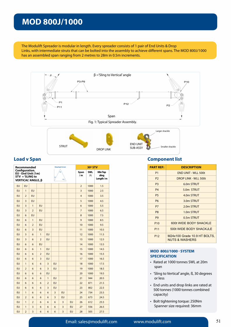
Email: [email protected] www.modulift.com
Recommended Configuration.EU - End Unit (1m)STV = ‘SLING to VERTICaL’ aNGLE, β
30º STV
Span / m
SWL/ t
Min Top sling
Length / m
EU EU 2 1000 1.5
EU 1 EU 3 1000 2.5
EU 2 EU 4 1000 3.5
EU 3 EU 5 1000 4.5
EU 3 1 EU 6 1000 5.5
EU 3 2 EU 7 1000 6.5
EU 6 EU 8 1000 7.5
EU 6 1 EU 9 1000 8.5
EU 6 2 EU 10 1000 9.5
EU 6 3 EU 11 1000 10.5
EU 3 6 1 EU 12 1000 11.5
EU 3 6 2 EU 13 1000 12.5
EU 6 6 EU 14 1000 13.5
EU 6 6 1 EU 15 1000 14.5
EU 6 6 2 EU 16 1000 15.5
EU 6 6 3 EU 17 1000 16.5
EU 1 6 6 3 EU 18 1000 17.5
EU 2 6 6 3 EU 19 1000 18.5
EU 6 6 6 EU 20 1000 19.5
EU 6 6 6 1 EU 21 944 20.5
EU 6 6 6 2 EU 22 871 21.5
EU 6 6 6 3 EU 23 802 22.5
EU 1 6 6 6 3 EU 24 734 23.5
EU 2 6 6 6 3 EU 25 673 24.5
EU 1 2 6 6 6 3 EU 26 612 25.5
EU 1 3 6 6 6 3 EU 27 556 26.5
EU 2 3 6 6 6 3 EU 28 505 27.5
The Modulift Spreader is modular in length. Every spreader consists of 1 pair of End Units & DropLinks, with intermediate struts that can be bolted into the assembly to achieve different spans. The MOD 800J/1000 has an assembled span ranging from 2 metres to 28m in 0.5m increments.
Component listPaRT REF: DESCRIPTION
P1 EnD UnIT - WLL 500t
P2 DROP LInK - WLL 500t
P3 6.0m STRUT
P4 5.0m STRUT
P5 4.0m STRUT
P6 3.0m STRUT
P7 2.0m STRUT
P8 1.0m STRUT
P9 0.5m STRUT
P10 600t WIDE BODY SHACKLE
P11 500t WIDE BODY SHACKJLE
P12 M24x100 Grade 10.9 HT BOLTS, NUTS & WASHERS
Load v Span
MOD 800J/1000 - SySTEM SPECIFICaTION• Ratedat1000tonnesSWLat20m span
• ‘SlingtoVertical’angle,ß,30degrees or less
• Endunitsanddroplinksareratedat 500 tonnes (1000 tonnes combined capacity)
• Bolttighteningtorque:250Nm Spanner size required: 36mm
MOD 800J/1000
Fig. 1: Typical Spreader Assembly.
β =’Sling to Vertical’ angle
STRUTDROP LInK
EnD UnIT SUB-ASSY
Larger shackle
Smaller shackle
Sling Angle Format
BSA
ISA
STV
51
SpanSpan

Email: [email protected] www.modulift.com52
Modulift, the market leaders in Spreader Beam design and manufacture, have extended their modular offering, by launching the CMOD Modular Spreader Frame! A truly adaptable frame that maintains its engineering principles as its configuration adapts. Designed with ease and economy in mind - the CMOD is simple to set up, manoeuvre, and reconfigure to any size frame - allowing for multiple uses and diverse application.
The CMOD is a modular frame utilising Corner Units which are compatible with our existing Spreader Beam Struts and is modular in length and width. Every CMOD Spreader Frame consists of 4 x Corner Units, with intermediate Struts that can be bolted into the assembly to achieve different spans. Existing customers can adapt their Spreader Beam into a frame, by simply bolting on the corresponding Corner Units and any additional Struts required.
Even the largest CMOD can be easily transported as the frame is broken down into modular parts, saving the cost of specialist transportation.
System SpecificationsThe CMOD comes in the following sizes: CMOD 6, CMOD 12, CMOD 24, CMOD 34, CMOD 50, CMOD 70 and CMOD 110
It spans from 0.5m/1’6”x 0.5m/1’6” to 16m/52’ x 16m/52’, whilst adapting to all rectangular shapes in between. The systems will lift up to 140t*
* The system’s SWL will de-rate as the shape of the frame becomes “more rectangular”. Higher capacities and longer spans in development.
Fig. 1: Example CMOD Modular Spreader Frame
Modulift Modular Spreader Frames work with existing struts from our Modular Spreader Beam range
CMOD Spreader Frame Range

Email: [email protected] www.modulift.com
The CMOD Spreader Frame is modular in span, and every frame consists of 4 Corner Units, with intermediate Struts that can be bolted into the assembly to achieve different spans. The CMOD 6 has an assembled span ranging from 0.5m by 0.5m to 2.5m by 2.5m and all spans inbetween.
PaRT REF: DESCRIPTION
P1 CORnER UnIT - Length: 0.25m each
P2 1000mm STRUT
P3 600mm STRUT
P4 300mm STRUT
P5 200mm STRUT
P6 100mm STRUT
P7 8.5t SHACKLE
P8 6.5t SHACKLE
P9 M10X30, GRADE 8.8, HT BOLTS nUTS & WASHERS
CMOD 6 - SySTEM SPECIFICaTION•Rated at a maximum of 8 tonnes SWL
• ‘SlingtoVertical’angle,ß,nomore than 45 degrees
•Corner Units are rated at 2 tonnes each (8t combined capacity)
• Bolttighteningtorque:60Nm Spanner size required: 17mm
CMOD 6 Spreader Frame
Assembled Frame:
P9
P7
P2 - P6P1
Span
β=‘SlingtoVertical’Angle(STV) β
P8
STRUT
CORnER UnIT
Component listTable 2
Fig. 1 Typical CMOD Spreader Frame Assembly
2.5 8
2 8 8
m 1.5 8 8 8
1 8 8 8 6
0.5 8 8 8 6 6
0.5 1 1.5 2 2.5
m
30° STV SWL = tonnes
Span/m
2.5 6
2 6 6
1.5 6 6 6
1 6 6 6 4
0.5 6 6 6 4 4
0.5 1 1.5 2 2.5
45° STV SWL = tonnes
Span/m
Span
/mSp
an/m
53

Email: [email protected] www.modulift.com54
The CMOD Spreader Frame is modular in span, and every frame consists of 4 Corner Units, with intermediate Struts that can be bolted into the assembly to achieve different spans. The CMOD 12 has an assembled span ranging from 0.5m by 0.5m to 4m by 4m and all spans inbetween.
Component listPaRT REF: DESCRIPTION
P1 CORnER UnIT - Length: 0.25m each
P2 1.5m STRUT
P3 1.0m STRUT
P4 0.75m STRUT
P5 0.5m STRUT
P6 0.25m STRUT
P7 8.5t SHACKLE
P8 6.5t SHACKLE
P9 M12X35, GRADE 8.8, HT BOLTS NUTS & WASHERS
CMOD 12 - SySTEM SPECIFICaTION•Rated at a maximum of 16 tonnes SWL
•Sling to Vertical Angle, β, no more than 45 degrees
•Corner Units are rated at 4 tonnes each (16t combined capacity)
•Bolt tightening torque: 90Nm Spanner size required: 19mm
CMOD 12 Spreader Frame
STRUT
P9
P7
P2 - P6P1
Span
β=‘SlingtoVertical’Angle(STV) β
P8
Table 2
STRUT
Assembled Frame: CORnER UnIT
Fig. 1 Typical CMOD Spreader Frame Assembly
4 16
3.5 16 16
3 16 16 15
2.5 16 16 15 14
2 16 16 16 14 13
1.5 16 16 16 16 14 12
1 16 16 16 16 16 14 12
0.5 16 16 16 16 16 16 14 12
0.5 1 1.5 2 2.5 3 3.5 4
4 9
3.5 9 9
3 9 9 8
2.5 9 9 8 8
2 9 9 9 8 7
1.5 9 9 9 9 8 6
1 9 9 9 9 9 8 6
0.5 9 9 9 9 9 9 8 6
0.5 1 1.5 2 2.5 3 3.5 4
30° STV SWL = tonnes
45° STV SWL = tonnes
Span
/mSp
an/m
Span/m
Span/m

Email: [email protected] www.modulift.com
The CMOD Spreader Frame is modular in span, and every frame consists of 4 Corner Units, with intermediate Struts that can be bolted into the assembly to achieve different spans. The CMOD 24 has an assembled span ranging from 1m by 1m to 6m by 6m and all spans inbetween.
PaRT REF: DESCRIPTION
P1 CORnER UnIT - Length: 0.5m each
P2 2.0m STRUT
P3 1.0m STRUT
P4 0.5m STRUT
P5 17t SHACKLE
P6 12t SHACKLE
P7 M20X50, GRADE 8.8, HT BOLTS nUTS & WASHERS
CMOD 24 - SySTEM SPECIFICaTION• Ratedatamaximumof30tonnes SWL
• ‘SlingtoVertical’angle,ß,nomore than 45 degrees
• CornerUnitsareratedat7.5tonnes each (30t combined capacity)
• Bolttighteningtorque:150Nm Spanner size required: 30mm
CMOD 24 Spreader Frame
Component listTable 2
P7
P5
P2 - P4P1
Span
β=‘SlingtoVertical’Angle(STV)
β
P6
STRUT
Assembled Frame: CORnER UnIT
Fig. 1 Typical CMOD Spreader Frame Assembly
6 13
5 17 12
4 19 13 10
3 19 19 13 10
2 19 19 17 13 9
1 19 19 19 13 12 9
1 2 3 4 5 6
6 23
5 30 21
4 30 24 19
3 30 30 24 18
2 30 30 30 24 17
1 30 30 30 24 22 16
1 2 3 4 5 6
Span
/mSp
an/m
Span/m
Span/m
30° STV SWL = tonnes
45° STV SWL = tonnes
55
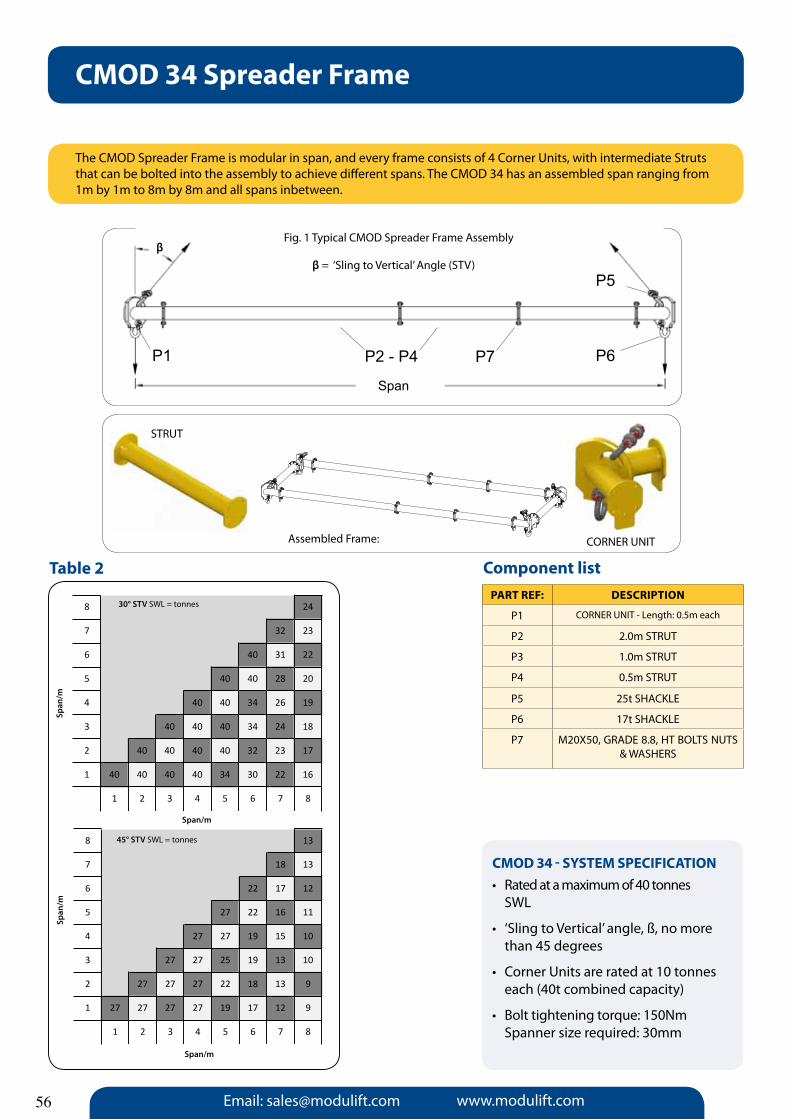
Email: [email protected] www.modulift.com56
The CMOD Spreader Frame is modular in span, and every frame consists of 4 Corner Units, with intermediate Struts that can be bolted into the assembly to achieve different spans. The CMOD 34 has an assembled span ranging from 1m by 1m to 8m by 8m and all spans inbetween.
PaRT REF: DESCRIPTION
P1 CORnER UnIT - Length: 0.5m each
P2 2.0m STRUT
P3 1.0m STRUT
P4 0.5m STRUT
P5 25t SHACKLE
P6 17t SHACKLE
P7 M20X50, GRADE 8.8, HT BOLTS nUTS & WASHERS
CMOD 34 - SySTEM SPECIFICaTION•Rated at a maximum of 40 tonnes SWL
• ‘SlingtoVertical’angle,ß,nomore than 45 degrees
• CornerUnitsareratedat10tonnes each (40t combined capacity)
• Bolttighteningtorque:150Nm Spanner size required: 30mm
CMOD 34 Spreader Frame
Component listTable 2
P7
P5
P2 - P4P1
Span
β=‘SlingtoVertical’Angle(STV) β
P6
STRUT
Assembled Frame: CORnER UnIT
Fig. 1 Typical CMOD Spreader Frame Assembly
8 24
7 32 23
6 40 31 22
5 40 40 28 20
4 40 40 34 26 19
3 40 40 40 34 24 18
2 40 40 40 40 32 23 17
1 40 40 40 40 34 30 22 16
1 2 3 4 5 6 7 8
8 13
7 18 13
6 22 17 12
5 27 22 16 11
4 27 27 19 15 10
3 27 27 25 19 13 10
2 27 27 27 22 18 13 9
1 27 27 27 27 19 17 12 9
1 2 3 4 5 6 7 8
30° STV SWL = tonnes
45° STV SWL = tonnes
Span
/mSp
an/m
Span/m
Span/m

Email: [email protected] www.modulift.com
The CMOD Spreader Frame is modular in span, and every frame consists of 4 Corner Units, with intermediate Struts that can be bolted into the assembly to achieve different spans. The CMOD 50 has an assembled span ranging from 1m by 1m to 11m by 11m and all spans inbetween.
PaRT REF: DESCRIPTION
P1 CORnER UnIT - Length: 0.5m each
P2 4.0m STRUT
P3 2.0m STRUT
P4 1.0m STRUT
P5 0.5m STRUT
P6 35t SHACKLE
P7 25t SHACKLE
P8 M20X65, GRADE 8.8, HT BOLTS nUTS & WASHERS
CMOD 50 - SySTEM SPECIFICaTION•Rated at a maximum of 60 tonnes SWL
• ‘SlingtoVertical’angle,ß,nomore than 45 degrees
•Corner Units are rated at 15 tonnes each (60t combined capacity)
• Bolttighteningtorque:150Nm Spanner size required: 30mm
CMOD 50 Spreader Frame
Component listTable 2
P8
P6
P2 - P5P1
Span
β=‘SlingtoVertical’Angle(STV)
β
P7
STRUT
Assembled Frame: CORnER UnIT
Fig. 1 Typical CMOD Spreader Frame Assembly
11 32
10 41 31
9 50 39 29
8 50 48 37 28
7 60 50 45 35 27
6 60 60 50 43 33 26
5 60 60 60 50 40 32 25
4 60 60 60 50 49 38 31 24
3 60 60 60 60 50 47 37 30 23
2 60 60 60 60 60 50 45 36 29 23
1 60 60 60 60 60 60 50 44 35 28 22
1 2 3 4 5 6 7 8 9 10 11
11 18
10 23 17
9 28 21 16
8 28 27 20 15
7 34 28 25 19 14
6 40 34 28 24 18 14
5 40 40 34 28 23 17 13
4 50 40 40 28 28 21 17 13
3 50 50 40 40 28 26 21 16 12
2 50 50 50 40 34 28 25 20 16 12
1 50 50 50 50 40 34 28 25 20 15 12
1 2 3 4 5 6 7 8 9 10 11
30° STV SWL = tonnes
45° STV SWL = tonnes
Span
/m
Span/m
Span/m
Span
/m
57

Email: [email protected] www.modulift.com58
The CMOD Spreader Frame is modular in span, and every frame consists of 4 Corner Units, with intermediate Struts that can be bolted into the assembly to achieve different spans. The CMOD 70 has an assembled span ranging from 1m by 1m to 12m by 12m and all spans inbetween.
PaRT REF: DESCRIPTION
P1 CORnER UnIT - Length: 0.5m each
P2 4.0m STRUT
P3 2.0m STRUT
P4 1.0m STRUT
P5 0.5m STRUT
P6 42.5t SHACKLE
P7 35t SHACKLE
P8 M20X65, GRADE 8.8, HT BOLTS nUTS & WASHERS
CMOD 70 - SySTEM SPECIFICaTION•Rated at a maximum of 80 tonnes SWL
• ‘SlingtoVertical’angle,ß,nomore than 45 degrees
• CornerUnitsareratedat20tonnes each (80t combined capacity)
• Bolttighteningtorque:150Nm Spanner size required: 30mm
CMOD 70 Spreader Frame
Component listTable 2
P8
P6
P2 - P5P1
Span
β=‘SlingtoVertical’Angle(STV) β
P7
STRUT
Assembled Frame: CORnER UnIT
Fig. 1 Typical CMOD Spreader Frame Assembly
12 63
11 70 60
10 80 70 58
9 80 80 70 55
8 80 80 80 67 53
7 80 80 80 70 65 51
6 80 80 80 70 60 62 49
5 80 80 80 80 70 60 60 47
4 80 80 80 80 80 70 60 58 46
3 80 80 80 80 80 80 70 60 56 45
2 80 80 80 80 80 80 70 70 60 55 44
1 80 80 80 80 80 80 80 70 70 60 54 44
1 2 3 4 5 6 7 8 9 10 11 12
12 36
11 40 34
10 40 40 33
9 46 40 40 31
8 57 46 40 38 30
7 60 57 46 40 37 29
6 60 60 57 40 34 35 28
5 60 60 60 50 40 34 34 27
4 60 60 60 60 50 40 34 33 26
3 60 60 60 60 60 50 40 34 32 26
2 60 60 60 60 60 60 50 40 34 31 25
1 60 60 60 60 60 60 60 50 40 34 31 24
1 2 3 4 5 6 7 8 9 10 11 12
Span
/mSp
an/m
Span/m
Span/m
30° STV SWL = tonnes
45° STV SWL = tonnes

Email: [email protected] www.modulift.com
System Benefits• Cheaper and easier to transport than a fixed system• Easy to set up, handle and manoeuvre• Re-configure the frame to any size to allow for multiple uses • The corner plate has a bow (like the shackle). This means that a reversed Shackle can contact the
plate‘bowtobow’allowingittoeasilyrotatetosuitanyangleofslingandsetupofframewithoutde-rating the Shackle
Design StrengthsThe plate is made of high strength carbon steel and is specifically designed to withstand any bending, and transfers the compression to the strut in an almost purely axial form. The system was designed to BS En 13155 – non Fixed Lifting Load Attachments and the method of Shackle connection has been approved by Van Beest.
CMOD T-piecesElaborating on this popular concept Modulift has now developed a T-Piece to work in conjunction with the CMOD. This allows the frame to become a 6-point lift, (8-point,10-point and so forth on request) adding yet another dimension to your Modulift equipment. Spans of up to 40m x 16m and capacities of up to 200t are available as standard.
CMOD & Beyond
59

Email: [email protected] www.modulift.com60
Lattice Spreader Beams
The Modulift Lattice System (MLS) is a light-weight modular spreader suitable for long, light loads, and has been specially developed to suit roofing sheets.Maximum spans from 6m up to 42m in 3m increments are achievable using this system. Lower support slings must be attached to the frames every 2m to ensure a uniformly distributed load.
3m
3m
1m
TYPE 1:100KG
TYPE 2:137KG
CROSS BAR: 7.5KG
FRAMES
TYPE 3:17.5 KG
CONNECTION PIN
Components
assembly
CONNECTION JOINTS -USE 4 no. CONNECTION PINS PER JOINT.
Max. 6.5t shackle
Max. 3.25t shackle
TYPICAL CROSS BAR CONNECTION
ConnectionPins - 2 perCross Beam
SPREaDER SySTEM SPECIFICaTION• Rated at a maximum of 3 tonnes WLL(Upto 24m Span)
• ‘SlingtoVertical’angle,ß,45degreesor less
• Liftingpoints:Slingscanbeconnectedto weld eyes on ends of 1m span cross bars, or to weld eyes on underside of frames.

Email: [email protected] www.modulift.com
Lattice Spreader Beam 6 - 24m Span
6m Spreader : 2.2m9m Spreader: 4.3m12m Spreader: 2.2m15m Spreader: 4.3m18m Spreader: 6.5m21m Spreader: 8.7m24m Spreader: 10.8m
These sling lengths areessential to ensure the Sling to Vertical Angle is 45 degrees or less.
Top Sling Minimum Length
Configuration
Lifting Points/Load Connection Points
SPREaDER CONFIGURaTION No. of Crossbeams
6m 2 3 2 3 or 4
9m 2 1 3 2 6
12m 1 2 3 2 1 7
15m 1 2 1 3 2 1 8
18m 1 2 1 3 1 2 1 10
21m 1 2 1 1 3 1 2 1 11
24m 1 2 1 1 3 1 1 2 1 13
1 = Type 1 Frame 2 = Type 2 Frame 3 = Type 3 Frame
Maximum 1.5m overhang of roofing sheet per end
= connection point for cross bar, and/or con-nection point for sling to weld eye.
318 KG 6m Spreader:
327 KG 6m Spreader:Alternative
444 KG 9m Spreader:
552 KG 12m Spreader:
661 KG 15m Spreader:
778 KG 18m Spreader:
1005 KG24m Spreader:
21m Spreader:
LC =8; CB = 6 PINS
LC =8; CB = 8 PINS
LC =12; CB = 12 PINS
LC =16; CB = 14 PINS
LC =20; CB = 16 PINS
LC =24; CB = 20PINS
LC =32; CB = 26 PINS
887 KG
LC = Lattice ConnectionsCB = Cross Beams
LC =28; CB = 22 PINS
59
45º

Email: [email protected] www.modulift.com
The Modulift Lattice System (MLS) is a light-weight modular spreader suitable for long, light loads, and has been specially developed to suit roofing sheets.Maximum spans from 6m up to 42m in 3m increments are achievable using this system. Lower support slings must be attached to the frames every 2m to ensure a uniformly distributed load.
3m
3m
1m
TYPE 1:100KG
TYPE 2:137KG
CROSS BAR: 7.5KG
FRAMES
TYPE 3:17.5 KG
CONNECTION PIN
Max. 3.25t shackle
TYPICAL CROSS BAR CONNECTION
Lattice Spreader Beam - 27m Span
SPREaDER CONFIGURaTION No. of Crossbeams
27m 1 2 1 1 1 3 1 1 2 1 15
1 = Type 1 Frame x 7 2 = Type 2 Frame x 23 = Type 3 Frame x 1
Maximum 1.5m overhang of roofing sheet per end
LaTTICE SPREaDER SPECIFICaTION• Rated at a maximum of 2 tonnes WLL - Uniformly Distributed Load only (Up to 27m span)
• ‘SlingtoVertical’angle,ß,45degrees or less
• Lifting points: Slings can be connected to weld eyes on ends of 1m span cross bars, or to weld eyes on underside of frames
•The sling arrangement must not be modified without Modulift’s written approval
CONNECTION PINS -2 PER CROSS BEAM
CONNECTION JOINTS -USE 4 no. CONNECTION PINS PER JOINT.
Max. 6.5t shackle
Components
assembly
62
Total weight = 1121kg
assembled Lattice Spreader Beam
Top Sling Min Length = 13m

Email: [email protected] www.modulift.com 63
The Modulift Lattice System (MLS) is a light-weight modular spreader suitable for long, light loads, and has been specially developed to suit roofing sheets.Maximum spans from 6m up to 42m in 3m increments are achievable using this system. Lower support slings must be attached to the frames every 2m to ensure a uniformly distributed load.
3m
3m
1m
TYPE 1:100KG
TYPE 2:137KG
CROSS BAR: 7.5KG
FRAMES
TYPE 3:17.5 KG
CONNECTION PIN
Max. 3.25t shackle
TYPICAL CROSS BAR CONNECTION
Lattice Spreader Beam - 30m Span
SPREaDER CONFIGURaTION No. of Crossbeams
30m 1 2 1 1 1 3 1 1 1 2 1 16
1 = Type 1 Frame x 8 2 = Type 2 Frame x 23 = Type 3 Frame x 1
Maximum 1.5m overhang of roofing sheet per end
LaTTICE SPREaDER SPECIFICaTION• Rated at a maximum of 2 tonnes WLL - Uniformly Distributed Load only (Up to 30m span)
• ‘SlingtoVertical’angle,ß,45degrees or less
• Lifting points: Slings can be connected to weld eyes on ends of 1m span cross bars, or to weld eyes on underside of frames
•The sling arrangement must not be modified without Modulift’s written approval
CONNECTION PINS -2 PER CROSS BEAM
CONNECTION JOINTS -USE 4 no. CONNECTION PINS PER JOINT.
Max. 6.5t shackle
Components
assembly
Total weight = 1231kg
assembled Lattice Spreader Beam
Top Sling Min Length = 15m
Wire RopeCentred Sling Support
Chain Block
Use round/webbing sling to connect chain block and Spreader Beam

Email: [email protected] www.modulift.com
The Modulift Lattice System (MLS) is a light-weight modular spreader suitable for long, light loads, and has been specially developed to suit roofing sheets.Maximum spans from 6m up to 42m in 3m increments are achievable using this system. Lower support slings must be attached to the frames every 2m to ensure a uniformly distributed load.
3m
3m
1m
TYPE 1:100KG
TYPE 2:137KG
CROSS BAR: 7.5KG
FRAMES
TYPE 3:17.5 KG
CONNECTION PIN
Max. 3.25t shackle
TYPICAL CROSS BAR CONNECTION
Lattice Spreader Beam - 33m Span
SPREaDER CONFIGURaTION No. of Crossbeams
33m 1 2 1 1 1 1 3 1 1 1 2 1 18
1 = Type 1 Frame x 9 2 = Type 2 Frame x 23 = Type 3 Frame x 1
Maximum 1.5m overhang of roofing sheet per end
LaTTICE SPREaDER SPECIFICaTION• Rated at a maximum of 2 tonnes WLL - Uniformly Distributed Load only (Up to 33m span)
• ‘SlingtoVertical’angle,ß,45degrees or less
• Lifting points: Slings can be connected to weld eyes on ends of 1m span cross bars, or to weld eyes on underside of frames
•The sling arrangement must not be modified without Modulift’s written approval
CONNECTION PINS -2 PER CROSS BEAM
CONNECTION JOINTS -USE 4 no. CONNECTION PINS PER JOINT.
Max. 6.5t shackle
assembly
64
Components
Total weight = 1347kg
assembled Lattice Spreader Beam
Top Sling Min Length = 17.5m
Wire RopeCentred Sling Support
Chain Block
Use round/webbing sling to connect chain block and Spreader Beam

Email: [email protected] www.modulift.com 65
The Modulift Lattice System (MLS) is a light-weight modular spreader suitable for long, light loads, and has been specially developed to suit roofing sheets.Maximum spans from 6m up to 42m in 3m increments are achievable using this system. Lower support slings can be attached to the frames every 2m to ensure a uniformly distributed load.
3m
3m
1m
TYPE 1:100KG
TYPE 2:137KG
CROSS BAR: 7.5KG
FRAMES
TYPE 3:17.5 KG
CONNECTION PIN
Max. 3.25t shackle
TYPICAL CROSS BAR CONNECTION
Lattice Spreader Beam - 36m Span
SPREaDER CONFIGURaTION No. of Crossbeams
36m 2 1 2 1 1 2 3 2 1 1 2 1 2 19
1 = Type 1 Frame x 6 2 = Type 2 Frame x 63 = Type 3 Frame x 1
Maximum 1.5m overhang of roofing sheet per end
LaTTICE SPREaDER SPECIFICaTION• Rated at a maximum of 2 tonnes WLL - Uniformly Distributed Load only (Up to 36m span)
• ‘SlingtoVertical’angle,ß,45degrees or less
• Lifting points: Slings can be connected to weld eyes on ends of 1m span cross bars, or to weld eyes on underside of frames
•The sling arrangement must not be modified without Modulift’s written approval
CONNECTION PINS -2 PER CROSS BEAM
CONNECTION JOINTS -USE 4 no. CONNECTION PINS PER JOINT.
Max. 6.5t shackle
Components
assembly
Total weight = 1604kg
assembled Lattice Spreader Beam
Top Sling Min Length = As shown above
22m 18m 13m 22m18m2.6m

Email: [email protected] www.modulift.com
The Modulift Lattice System (MLS) is a light-weight modular spreader suitable for long, light loads, and has been specially developed to suit roofing sheets.Maximum spans from 6m up to 42m in 3m increments are achievable using this system. Lower support slings must be attached to the frames every 2m to ensure a uniformly distributed load.
3m
3m
1m
TYPE 1:100KG
TYPE 2:137KG
CROSS BAR: 7.5KG
FRAMES
TYPE 3:17.5 KG
CONNECTION PIN
Max. 3.25t shackle
TYPICAL CROSS BAR CONNECTION
Lattice Spreader Beam - 42m Span
LaTTICE SPREaDER SPECIFICaTION• Rated at a maximum of 1 tonne WLL - Uniformly Distributed Load only (Up to 42m span)
• Lifting points: Slings can be connected to weld eyes on ends of 1m span cross bars, or to weld eyes on underside of frames
•Theslingarrangementmustnotbe modified without Modulift’s written approval.
CONNECTION PINS -2 PER CROSS BEAM
CONNECTION JOINTS -USE 4 no. CONNECTION PINS PER JOINT.
Max. 6.5t shackle
Component list
assembly
66
Total weight = 1822kg
assembled Lattice Spreader Beam
Top Sling Min Length = As shown above
SPREaDER CONFIGURaTION No. of Crossbeams
42m 2 1 1 2 1 1 2 3 2 1 1 2 1 2 21
1 = Type 1 Frame x 8 2 = Type 2 Frame x 63 = Type 3 Frame x 1
Maximum 1.5m overhang of roofing sheet per end
37m33.5m
3 Leg Assy33.5m 37m

Email: [email protected] www.modulift.com 67
Where To Buy & Contacts
Modulift is here for you every step of the way ... UK Head Office Contact details: Managing Director – Sarah Spivey [email protected]
Technical Director – Sue [email protected]
QuEnSH Manager – Simon [email protected]
For Distributor Operations/Training or to become a Distributor
International Business Development ManagersMalcolm Peacock - [email protected] in UAE - Tel: +971 56 2199 663
Serafim Marinho - [email protected]
Based in Portugal - Tel: +351 93 7409 345
For Sales Enquiries
Sales Executive – Chris Schwab [email protected]
For Marketing Enquiries
Marketing Manager - Wendy Armstrong
Marketing Executive– Sophie Briggs [email protected]
For accounts & Order Enquiries
Financial Controller – Paul [email protected]
For Production & administrational Enquiries
Production Administrator - Lydia Davies [email protected]
Tel: +44 (0) 1202 621511 00 11 44 1202 621511 (USa & Canada)Fax: +44 (0) 1202 632811


![[2019] UKUT 0170 (TCC) · incurred. The Claim sought a refund of the remaining 50% of the VAT incurred. 3. In a decision dated 19 January 2018 (‘the Decision’), Mr Kevin Gair](https://static.fdocuments.net/doc/165x107/5f20e37f3cba8f550837da8d/2019-ukut-0170-tcc-incurred-the-claim-sought-a-refund-of-the-remaining-50.jpg)

