WORK ORDER 189 UPPER BOONES FERRY ROAD AND …
315
CONTRACT DOCUMENTS FOR THE CONSTRUCTION OF WORK ORDER 189 UPPER BOONES FERRY ROAD AND MONROE PARKWAY PAVEMENT REHABILITATION FOR City of Lake Oswego MAY 2016 City of Lake Oswego Public Works Department Engineering Services Division 380 A Avenue P. O. Box 369 Lake Oswego, Oregon 97034
Transcript of WORK ORDER 189 UPPER BOONES FERRY ROAD AND …

CONTRACT DOCUMENTS FOR THE CONSTRUCTION OF
WORK ORDER 189 UPPER BOONES FERRY ROAD AND MONROE PARKWAY PAVEMENT REHABILITATION
FOR
City of Lake Oswego
MAY 2016
City of Lake Oswego Public Works Department Engineering Services Division 380 A Avenue P. O. Box 369 Lake Oswego, Oregon 97034


16‐189 Table of Contents ‐ 1
CONTRACT DOCUMENTS FOR THE
CONSTRUCTION OF WORK ORDER 189
UPPER BOONES FERRY ROAD AND MONROE PARKWAY PAVEMENT REHABILITATION
FOR CITY OF LAKE OSWEGO, OREGON
TABLE OF CONTENTS
VOLUME 1 OF 2 Pages
BIDDING REQUIREMENTS
Invitation for Bids ................................................................................................... 1 pg. Instructions to Bidders ........................................................................................ 10 pgs. Bid Form ................................................................................................................ 8 pgs. First‐Tier Subcontractor Disclosure Form .............................................................. 1 pg. Bid Bond ................................................................................................................ 2 pgs.
CONTRACT FORMS
Public Works/Improvement Contract ................................................................... 3 pgs. Public Improvement Contract Provisions ............................................................. 3 pgs. Public Works Contract Provisions .......................................................................... 1 pg. Performance Bond ................................................................................................ 3 pgs. Payment Bond ....................................................................................................... 3 pgs.
CONDITIONS OF THE CONTRACT
Standard General Conditions ............................................................................. 42 pgs. Supplementary General Conditions ...................................................................... 9 pgs.
BOLI FORMS
BOLI Forms ............................................................................................................ 3 pgs.

16‐189 Table of Contents ‐ 2
TECHNICAL SPECIFICATIONS
DIVISION 1, GENERAL REQUIREMENTS Section 01010, Summary of Work ........................................................................ 2 pgs. Section 01015, Work Sequence and Constraints .................................................. 2 pgs. Section 01025, Measurement and Payment ........................................................ 8 pgs. Section 01100, Special Provisions ....................................................................... 13 pgs. Section 01300, Submittals .................................................................................... 3 pgs. DIVISION 2, SITE WORK Section 02100, Site Preparation ........................................................................... 3 pgs. Section 02200, Earthwork ................................................................................... 11 pgs. Section 02240, Geotextiles ................................................................................... 2 pgs. Section 02241, Composite Grid Paving Interlayer ................................................ 4 pgs. Section 02520, Base and Leveling Course for Paving ........................................... 2 pgs. Section 02530, Asphalt Concrete (AC) Pavement ............................................... 17 pgs. Section 02580, Pavement Markings – Striping (Thermoplastic) .......................... 2 pgs. Section 02585, Pavement Markings – Legends and Bars (Thermoplastic) ........... 2 pgs. Section 02590, Pavement Markers ........................................................................ 1 pg. Section 02610, Ductile Iron Pipe and Fittings for Water and Other Liquids ................................................................................................................... 7 pgs. Section 02611, Valves .......................................................................................... 4 pgs. Section 0619, Water Service Lines, Valves and Appurtenances ........................... 5 pgs. Section 02700, Sanitary Sewerage and Drainage ............................................... 24 pgs. Section 02810, Irrigation Systems ...................................................................... 12 pgs. Section 02900, Landscaping ................................................................................ 12 pgs.
DIVISION 3, CONCRETE Section 03100, Concrete Work ........................................................................... 28 pgs. Section 03320, Concrete Sidewalks, Ramps, Driveways and Curbs ................... 14 pgs.
ODOT SPECIAL PROVISIONS
ODOT 00305, Construction Survey Work .............................................................. 1 pg. ODOT 00610, Reconditioning Existing Roadway ................................................... 1 pg. ODOT 00620, Cold Plane Pavement Removal ....................................................... 1 pg. ODOT 00930, Metal Sign Supports ........................................................................ 1 pg. ODOT 00940, Signs ................................................................................................. 1 pg. ODOT 00990, Traffic Signals ................................................................................... 1 pg.

16‐189 Table of Contents ‐ 3
ODOT STANDARD SPECIFICATIONS
ODOT 00610, Reconditioning Existing Roadway .................................................. 2 pgs. ODOT 00620, Cold Plane Pavement Removal ...................................................... 2 pgs. ODOT 00930, Metal Sign Supports ....................................................................... 6 pgs. ODOT 00940, Signs ................................................................................................ 5 pgs. ODOT 00900, Traffic Signals ................................................................................ 10 pgs.
SPECIAL PERMITS
Traffic Control Plan Application ............................................................................ 2 pgs. Erosion Prevention and Sediment Control Permit Application ............................ 2 pgs.
VOLUME 2 OF 2 Plans .............................................................................................................................. 29 pgs. See Sheet Number G‐1 for Drawing Index


INVITATION FOR BIDS FOR
WORK ORDER 189 UPPER BOONES FERRY ROAD AND MONROE PARKWAY
PAVEMENT REHABILITATION FOR
CITY OF LAKE OSWEGO LAKE OSWEGO, OREGON
Sealed proposals for Work Order 189 – Upper Boones Ferry Road and Monroe Parkway for the City of Lake Oswego will be received by Crystal M. Shum, PE, Project Manager, at the 3rd floor reception desk in Lake Oswego City Hall, 380 A Avenue, Lake Oswego, Oregon, 97034 until 2:00 PM local time, on Tuesday, June 21, 2016 and then will be publicly opened and read. The scope of work consists of pavement reconstruction, sidewalk and curb ramp construction/reconstruction, catch basin replacements, pavement marking and marker installation, and signal loop installation for Upper Boones Ferry Road and Monroe Parkway. No proposal will be considered by the Owner unless the proposal contains, or is accompanied by, a statement by the bidder as part of the proposal that the provision required by ORS 279C.840 pertaining to prevailing wages shall be included in the contract. The contract documents may be reviewed, examined, and copies obtained at the City Engineering Dept., 3rd Floor, Lake Oswego City Hall, 380 A Avenue, Lake Oswego, Oregon between the hours of 8:00 a.m. and 5:00 p.m., Monday through Friday, except legal holidays. Copies may be obtained upon payment of a non‐refundable fee of $25. Copies of the contract documents may also be obtained by mail upon request (phone: 503.635.0270; fax: 503.635.0269) and upon the receipt of an additional $5.00 per contract document to cover postage and handling. Requests sent through the mail shall be addressed to the Engineering Department, City of Lake Oswego, PO Box 369, Lake Oswego, Oregon 97034. Online: To download the contract documents, and to receive notifications, addenda, and view the Planholder’s list, a person or company must create an account and add its individual name or company to the Planholder’s list. Go to the following link to get more information, instructions, and to sign up http://www.ci.oswego.or.us/publicworks/bid‐rfp‐information. If you have website questions concerning this invitation, please contact Donna Broadhurst at 503.635.0266. Contractors must be prequalified by the Department of Transportation in order to enter into a contract with the Owner prior to the opening of bids. Prequalification application forms may be obtained from the Oregon Department of Transportation Office of Procurement, MS#2‐2, 3930 Fairview Industrial Drive SE, Salem, OR 97302, or on‐line at https://www.oregon.gov/ODOT/CS/CONSTRUCTION/docs/PQ/Prequalification_RevisedAugust2015.pdf and must be submitted to the City no later than date and time set forth above for submission of the bid. The Owner will investigate and determine the qualifications of the apparent low bidder as part of its evaluation of the lowest responsive bid. Bidders are encouraged to visit the site of the Work during bid preparation. Clarifications to the Bidding Documents will be made by addenda only. Oral statements may not be relied upon and will not be binding or legally effective.
Published in the Daily Journal of Commerce on May 27 and June 1, 2016.

INSTRUCTION TO BIDDERS
16‐189 Instruction to Bidders ‐ 1
ARTICLE 1 ‐ DEFINED TERMS
1.01 Terms used in these Instructions to Bidders have the meanings indicated in the General Conditions and Supplementary Conditions. Additional terms used in these Instructions to Bidders have the meanings indicated below: A. Issuing Office‐‐The office from which the Bidding Documents are to be issued and where the bidding procedures are to be administered.
ARTICLE 2 ‐ COPIES OF BIDDING DOCUMENTS
2.01 Complete sets of the Bidding Documents in the number and for the deposit sum, if any, stated in the Advertisement or Invitation to Bid may be obtained from the Issuing Office.
City of Lake Oswego Engineering Department 3rd Floor, Lake Oswego City Hall 380 A Avenue Lake Oswego, OR 97034 OR Online: To download the contract documents, and to receive notifications, addenda, and view the Planholder’s list, a person or company must create an account and add its individual name or company to the Planholder’s list. Go to the following link to get more information, instructions, and to sign up http://www.ci.oswego.or.us/publicworks/bid‐rfp‐information.
2.02 Owner and Engineer, in making copies of Bidding Documents available on the above terms, do so only for the purpose of obtaining Bids for the Work and do not confer a license or grant for any other use.
ARTICLE 3 ‐ QUALIFICATIONS OF BIDDERS
3.01 To demonstrate minimum qualifications to perform the Work, each Bidder shall be prequalified with the Oregon Department of Transportation prior to the opening of bids. The class or classes of work for which bidders, or bidder’s subcontractors, if bidder is not prequalified in a designated class of work, must be prequalified are as follows: Highway, Roads, Streets:
Aggregate Bases
Asphalt Concrete Paving and Oiling (paving, chip sealing, crack sealing, slurry sealing, fog sealing)
Earthwork and Drainage (clearing, earthwork, blasting, riprap, culverts, manholes, inlets, storm sewers, sanitary systems)
Electrical (Traffic Signals, Illumination, Ramp Meters, Roadway Weather Information Systems (RWIS), Variable Message Signs (VMS), Traffic Cameras)
Erosion Control (temporary and permanent erosion control permit if required)
Miscellaneous Highway Appurtances (guardrail, barrier, curbs, walks, fences, protective screening, impact attenuators, cold plane pavement removal, rumble strips)
Pavement Markings (permanent, durable, markers, delineators)

INSTRUCTION TO BIDDERS
16‐189 Instruction to Bidders ‐ 2
Temporary Traffic Control (all temporary traffic control items including flaggers and pilot cars)
3.02 A contractor or subcontractor need not be licensed under ORS 468A.720 (asbestos removal). The Bidder shall submit copies of his/her letter of prequalification approval from the State of Oregon and completed application as part of his/her bid proposal. Prequalification forms may be obtained from the, Oregon Department of Transportation Office of Procurement, MS#2‐2, 3930 Fairview Industrial Drive SE, Salem, OR 97302. Or online at: https://www.oregon.gov/ODOT/CS/CONSTRUCTION/docs/PQ/Prequalification_RevisedAugust2015.pdf
ARTICLE 4 ‐ EXAMINATION OF BIDDING DOCUMENTS, OTHER RELATED DATA, AND SITE
4.01 Subsurface and Physical Conditions
A. Not Used 4.02 Underground Facilities A. Not Used 4.03 Hazardous Environmental Condition A. Not Used
4.04 Not Used 4.05 On request, Owner will provide Bidder access to the Site to conduct such examinations, investigations, explorations,
tests, and studies as Bidder deems necessary for submission of a Bid. Bidder shall fill all holes and clean up and restore the Site to its former condition upon completion of such explorations, investigations, tests, and studies. Bidder shall comply with all applicable Laws and Regulations relative to excavation and utility locates. 4.06 Reference is made to Article 7 of the Supplementary Conditions for the identification of the general nature of other work that is to be performed at the Site by Owner or others (such as utilities and other prime contractors) that relates to the Work contemplated by these Bidding Documents. On request, Owner will provide to each Bidder for examination access to or copies of Contract Documents (other than portions thereof related to price) for such other work. 4.07 It is the responsibility of each Bidder before submitting a Bid to: A. examine and carefully study the Bidding Documents, the other related data identified in the Bidding Documents, and any Addenda; B. visit the Site and become familiar with and satisfy Bidder as to the general, local, and Site conditions that may affect cost, progress, and performance of the Work; C. become familiar with and satisfy Bidder as to all federal, state, and local Laws and Regulations that may affect cost, progress, and performance of the Work;
D. Not Used E. obtain and carefully study (or accept consequences of not doing so) all additional or supplementary examinations, investigations, explorations, tests, studies, and data concerning conditions (surface,

INSTRUCTION TO BIDDERS
16‐189 Instruction to Bidders ‐ 3
subsurface, and Underground Facilities) at or contiguous to the Site which may affect cost, progress, or performance of the Work or which relate to any aspect of the means, methods, techniques, sequences, and procedures of construction to be employed by Bidder, including applying any specific means, methods, techniques, sequences, and procedures of construction expressly required by the Bidding Documents, and safety precautions and programs incident thereto; F. agree at the time of submitting its Bid that no further examinations, investigations, explorations, tests, studies, or data are necessary for the determination of its Bid for performance of the Work at the price(s) bid and within the times and in accordance with the other terms and conditions of the Bidding Documents; G. become aware of the general nature of the work to be performed by Owner and others at the Site that relates to the Work as indicated in the Bidding Documents; H. correlate the information known to Bidder, information and observations obtained from visits to the Site, reports and drawings identified in the Bidding Documents, and all additional examinations, investigations, explorations, tests, studies, and data with the Bidding Documents; I. promptly give Engineer written notice of all conflicts, errors, ambiguities, or discrepancies that Bidder discovers in the Bidding Documents and confirm that the written resolution thereof by Engineer is acceptable to Bidder; and J. determine that the Bidding Documents are generally sufficient to indicate and convey understanding of all
terms and conditions for the performance of the Work. 4.08 The submission of a Bid will constitute an incontrovertible representation by Bidder that Bidder has complied with every requirement of this Article 4, that without exception the Bid is premised upon performing and furnishing the Work required by the Bidding Documents and applying any specific means, methods, techniques, sequences, and procedures of construction that may be shown or indicated or expressly required by the Bidding Documents, that Bidder has given Engineer written notice of all conflicts, errors, ambiguities, and discrepancies that Bidder has discovered in the Bidding Documents and the written resolutions thereof by Engineer are acceptable to Bidder, and that the Bidding Documents are generally sufficient to indicate and convey understanding of all terms and conditions for performing and furnishing the Work.
ARTICLE 5 ‐ PRE‐BID CONFERENCE
5.01 A pre‐Bid conference will NOT be held.
INSTRUCTION TO BIDDERS
16‐189 Instruction to Bidders ‐ 4
ARTICLE 6 ‐ SITE AND OTHER AREAS
6.01 The Site is identified in the Bidding Documents. Easements for permanent structures or permanent changes in existing facilities are to be obtained and paid for by Owner unless otherwise provided in the Bidding Documents. All additional lands and access thereto required for temporary construction facilities, construction equipment, or storage of materials and equipment to be incorporated in the Work are to be obtained and paid for by Contractor.
ARTICLE 7 ‐ INTERPRETATIONS AND ADDENDA
7.01 All questions about the meaning or intent of the Bidding Documents are to be submitted to Engineer in writing. Interpretations or clarifications considered necessary by Engineer in response to such questions will be issued by Addenda mailed or delivered to all parties recorded by Engineer as having received the Bidding Documents. Questions received less than ten days prior to the date for opening of Bids may not be answered. Only questions answered by Addenda will be binding. Oral and other interpretations or clarifications will be without legal effect. 7.02 Addenda may be issued to clarify, correct, or change the Bidding Documents as deemed advisable by Owner or Engineer.
ARTICLE 8 ‐ BID SECURITY
8.01 A Bid must be accompanied by Bid security made payable to Owner in an amount of ten (10) percent of Bidder’s maximum Bid price and in the form of a Bid bond (on the form attached) issued by a surety meeting the requirements of Paragraphs 5.01 and 5.02 of the General Conditions. The bond shall be executed by a surety company authorized to transact business in the State of Oregon. 8.02 The Bid security of the Successful Bidder will be retained until such Bidder has executed the Contract Documents, furnished the required contract security and met the other conditions of the Notice of Award, whereupon the Bid security will be returned. If the Successful Bidder fails to execute and deliver the Contract Documents and furnish the required contract security within 15 days after the Notice of Award, Owner may annul the Notice of Award and the Bid security of that Bidder will be forfeited. The Bid security of other Bidders whom Owner believes to have a reasonable chance of receiving the award may be retained by Owner until the earlier of seven days after the Effective Date of the Agreement or 61 days after the Bid opening, whereupon Bid security furnished by such Bidders will be returned. 8.03 Bid security of other Bidders whom Owner believes do not have a reasonable chance of receiving the award will be returned within seven days after the Bid opening.

INSTRUCTION TO BIDDERS
16‐189 Instruction to Bidders ‐ 5
ARTICLE 9 ‐ CONTRACT TIMES
9.01 The number of days within which, or the dates by which, milestones are to be achieved and the Work is to be substantially completed and ready for final payment are set forth in the Agreement.
ARTICLE 10 ‐ LIQUIDATED DAMAGES
10.01 Provisions for liquidated damages, if any, are set forth in the Agreement.
ARTICLE 11 ‐ SUBSTITUTE AND “OR‐EQUAL” ITEMS
11.01 The Contract, if awarded, will be on the basis of materials and equipment specified or described in the Bidding Documents without consideration of possible substitute or “or‐equal” items. Whenever it is specified or described in the Bidding Documents that a substitute or “or‐equal” item of material or equipment may be furnished or used by Contractor if acceptable to Engineer, application for such acceptance will not be considered by Engineer until after the Effective Date of the Agreement.
ARTICLE 12 ‐ SUBCONTRACTORS, SUPPLIERS, AND OTHERS
12.01 If the Supplementary Conditions require the identity of certain Subcontractors, Suppliers, individuals, or entities to be submitted to Owner in advance of a specified date prior to the Effective Date of the Agreement, the apparent Successful Bidder, and any other Bidder so requested,
shall within five days after Bid opening, submit to Owner a list of all such Subcontractors, Suppliers, individuals, or entities proposed for those portions of the Work for which such identification is required. Such list shall be accompanied by an experience statement with pertinent information regarding similar projects and other evidence of qualification for each such Subcontractor, Supplier, individual, or entity if requested by Owner. If Owner or Engineer, after due investigation, has reasonable objection to any proposed Subcontractor, Supplier, individual, or entity, Owner may, before the Notice of Award is given, request apparent Successful Bidder to submit a substitute, without an increase in the Bid. 12.02 If apparent Successful Bidder declines to make any such substitution, Owner may award the Contract to the next lowest Bidder that proposes to use acceptable Subcontractors, Suppliers, individuals, or entities. Declining to make requested substitutions will not constitute grounds for forfeiture of the Bid security of any Bidder. Any Subcontractor, Supplier, individual, or entity so listed and against which Owner or Engineer makes no written objection prior to the giving of the Notice of Award will be deemed acceptable to Owner and Engineer subject to revocation of such acceptance after the Effective Date of the Agreement as provided in Paragraph 6.06 of the General Conditions. 12.03 Contractor shall not be required to employ any Subcontractor, Supplier, individual, or entity against whom Contractor has reasonable objection.

INSTRUCTION TO BIDDERS
16‐189 Instruction to Bidders ‐ 6
ARTICLE 13 ‐ PREPARATION OF BID
13.01 The Bid Form is included with the Bidding Documents. Additional copies may be obtained from the Engineer 13.02 All blanks on the Bid Form shall be completed by printing in ink or by typewriter and the Bid signed in ink. Erasures or alterations shall be initialed in ink by the person signing the Bid Form. A Bid price shall be indicated for each bid item, listed therein, or the words “No Bid,” “No Change,” or “Not Applicable” entered.
13.03 A Bid by a corporation shall be executed in the corporate name by the president or a vice‐president or other corporate officer accompanied by evidence of authority to sign. The corporate seal shall be affixed and attested by the secretary or an assistant secretary. The corporate address and state of incorporation shall be shown below the signature. 13.04 A Bid by a partnership shall be executed in the partnership name and signed by a partner (whose title must appear under the signature), accompanied by evidence of authority to sign. The official address of the partnership shall be shown below the signature. 13.05 A Bid by a limited liability company shall be executed in the name of the firm by a member and accompanied by evidence of authority to sign. The state of formation of the firm and the official address of the firm shall be shown below the signature. 13.06 A Bid by an individual shall show the Bidder’s name and official address. 13.07 A Bid by a joint venture shall be executed by each joint venturer in the
manner indicated on the Bid Form. The official address of the joint venture shall be shown below the signature. 13.08 All names shall be typed or printed in ink below the signatures. 13.09 The Bid shall contain an acknowledgment of receipt of all Addenda, the numbers of which shall be filled in on the Bid Form. 13.10 The address and telephone number for communications regarding the Bid shall be shown. The Bid shall contain evidence of Bidder’s authority and qualification to do business in the state where the Project is located or covenant to obtain such qualification prior to award of the Contract. Bidder’s state contractor license number, if any, shall also be shown on the Bid Form. If the contract is for a public work subject to ORS 279C.800 to 279C.870 or the Davis Bacon Act (40 U.S.C. 276a) no bid will be received or considered by the public contracting agency unless the bid contains a statement by the bidder as a part of its bid that the provisions of ORS 279C.840 or 40 U.S.C. 276a are to be complied with. No bid for a construction contract shall be received or considered by the City of Lake Oswego unless the bidder is registered, as appropriate for the Scope of Work, with the Construction Contractors Board or licensed by the State Landscape Contractors Board as required by ORS 671.530 and ORS 701.005. A Bidder shall certify that the bidder is not on a list created by the Construction Contractors Board under ORS 701.227 for bidders who are not qualified to hold a contract for a public improvement.

INSTRUCTION TO BIDDERS
16‐189 Instruction to Bidders ‐ 7
Each bid must identify whether the bidder is a resident bidder, as defined in ORS 279A.120.
ARTICLE 14 ‐ BASIS OF BID; COMPARISON OF BIDS
14.01 Unit Price A. Bidders shall submit a Bid on a unit price basis for each item of Work listed in the Bid schedule. B. The total of all estimated prices will be the sum of the products of the estimated quantity of each item and the corresponding unit price. The final quantities and Contract Price will be determined in accordance with Paragraph 11.03 of the General Conditions. C. Discrepancies between the multiplication of units of Work and unit prices will be resolved in favor of the unit prices. Discrepancies between the indicated sum of any column of figures and the correct sum thereof will be resolved in favor of the correct sum. Discrepancies between words and figures will be resolved in favor of the words. 14.02 The Bid price shall include such amounts as the Bidder deems proper for overhead and profit on account of cash allowances, if any, named in the Contract Documents as provided in Paragraph 11.02 of the General Conditions. 14.03 Bid prices will be compared after adjusting for differences in the time designated by Bidders for Substantial Completion. The adjusting amount will be determined at the rate set forth in the Contract Documents for liquidated damages for failing to achieve Substantial Completion
for each day before or after the desired date appearing in Article 9.
ARTICLE 15 ‐ SUBMITTAL OF BID
15.01 With each copy of the Bidding Documents, a Bidder is furnished one copy of the Bid Form, and, if required, the Bid Bond Form. The Bid Form is to be completed and submitted with the Bid security and the following data: A. Acknowledge receipt of Addenda. B. Attach Bid Security. C. Attach copy of Pre‐qualification
Application. Attach First‐Tier Subcontractor Disclosure Form (see form for filing dead line).
15.02 A Bid shall be submitted to the issuing office no later than the date and time prescribed and at the place indicated in the Advertisement or Invitation to Bid and shall be enclosed in an opaque sealed envelope plainly marked with the Project title (and, if applicable, the designated portion of the Project for which the Bid is submitted), the name and address of Bidder, and shall be accompanied by the Bid security and other required documents. If a Bid is sent by mail or other delivery system, the sealed envelope containing the Bid shall be enclosed in a separate envelope plainly marked on the outside with the notation “BID ENCLOSED.” Bids sent by facsimile will be considered non responsive and rejected.

INSTRUCTION TO BIDDERS
16‐189 Instruction to Bidders ‐ 8
ARTICLE 16 ‐ MODIFICATION AND WITHDRAWAL OF BID
16.01 A Bid may be modified or withdrawn by an appropriate document duly executed in the manner that a Bid must be executed and delivered to the place where Bids are to be submitted prior to the date and time for the opening of Bids. 16.02 If within 24 hours after Bids are opened, any Bidder files a duly signed written notice with Owner and promptly thereafter demonstrates to the reasonable satisfaction of Owner that there was a material and substantial mistake in the preparation of its Bid, that Bidder may withdraw its Bid, and the Bid security will be returned. Thereafter, if the Work is rebid, that Bidder will be disqualified from further bidding on the Work.
ARTICLE 17 ‐ OPENING OF BIDS
Bids will be opened at the time and place indicated in the Advertisement or Invitation to Bid and, unless obviously non‐responsive, read aloud publicly. An abstract of the amounts of the base Bids and major alternates, if any, will be made available to Bidders after the opening of Bids. For public improvement contracts greater than $100,000:
“Instructions for First Tier Subcontractor Disclosure”
Bidders are required to disclose information about certain first tier subcontractors when the contract value for a Public Improvement is greater than $100,000 (see ORS 279C.370. Specifically, when the contract amount of a
first tier subcontractor furnishing labor or labor and materials would be greater than or equal to: (i) 5% of the project bid, but at least $15,000, or (ii) $350,000 regardless of the percentage, the bidder must disclose the following information about that subcontract either in its Bid submission or within two hours after bid closing: The subcontractor’s name, The category of work that the subcontractor would be performing, The dollar value of each subcontract. If the bidder will not be using any subcontractors that are subject to the above disclosure requirements, the bidder is required to indicate “NONE” on the accompanying form. THE OWNER MUST REJECT A BID IF THE BIDDER FAILS TO SUBMIT THE DISCLOSUE FORM WITH THIS INFORMATION BY THE STATED DEADLINE.
ARTICLE 18 ‐ BIDS TO REMAIN SUBJECT TO ACCEPTANCE
18.01 All Bids will remain subject to acceptance for the period of time stated in the Bid Form, but Owner may, in its sole discretion, release any Bid and return the Bid security prior to the end of this period.
ARTICLE 19 – EVALUATION OF BIDS AND AWARD OF CONTRACT
19.01 Owner reserves the right to reject any or all Bids, including without limitation, nonconforming, nonresponsive, unbalanced, or conditional Bids. Owner further reserves
INSTRUCTION TO BIDDERS
16‐189 Instruction to Bidders ‐ 9
the right to reject the Bid of any Bidder whom it finds, after reasonable inquiry and evaluation, to not be responsible. Owner may also reject the Bid of any Bidder if Owner believes that it would not be in the best interest of the Project to make an award to that Bidder. Owner also reserves the right to waive all informalities not involving price, time, or changes in the Work and to negotiate contract terms with the Successful Bidder. 19.02 More than one Bid for the same Work from an individual or entity under the same or different names will not be considered. Reasonable grounds for believing that any Bidder has an interest in more than one Bid for the Work may be cause for disqualification of that Bidder and the rejection of all Bids in which that Bidder has an interest. 19.03 In evaluating Bids, Owner will consider whether or not the Bids comply with the prescribed requirements, and such alternates, unit prices and other data, as may be requested in the Bid Form or prior to the Notice of Award. 19.04 In evaluating Bidders, Owner will consider the qualifications of Bidders and may consider the qualifications and experience of Subcontractors, Suppliers, and other individuals or entities proposed for those portions of the Work for which the identity of Subcontractors, Suppliers, and other individuals or entities must be submitted as provided in the Supplementary Conditions. 19.05 Owner may conduct such investigations as Owner deems necessary to establish the responsibility, qualifications, and financial ability of Bidders, proposed Subcontractors, Suppliers, individuals, or entities to perform the Work in accordance with the Contract Documents.
19.06 If the contract is to be awarded, it will be awarded to the Bidder who submits the lowest responsive, responsible bid and whose evaluation by Owner indicates that the award will be in the best interests of the Project. 19.07 If the contract is intended to be awarded, Owner will issue a written Notice of Intent to Award to each Bidder who submitted a Bid at least ten (10) days before the award of a Contract. 19.08 If the contract is to be awarded, Owner will give successful Bidder a Notice of Award within thirty (30) days after the date the Notice of Intent to Award is issued. 19.09 Notwithstanding Lake Oswego Public Contracting Procedures Rule 103‐0450, any Bidder who believes they will be adversely affected or aggrieved by Owner’s intent to award the contract to the apparent low bidder, shall have seven (7) calendar days from the date the Notice of Intent to Award is issued to submit to the Owner, at its Issuing Office, a written protest of such intended award. The written protest shall, at a minimum, set forth the specific reasons why the protester believes that the contract should not be awarded to the apparent low Bidder and certify that the Protester’s Bid is itself responsive in all respects to the Owner’s Bidding requirements. Owner will furnish any such protesting Bidder written notice of its decision on such protests prior to contract award.
ARTICLE 20 ‐ CONTRACT SECURITY AND INSURANCE
20.01 Article 5 of the General Conditions, as may be modified by the Supplementary Conditions, sets forth Owner’s requirements

INSTRUCTION TO BIDDERS
16‐189 Instruction to Bidders ‐ 10
as to performance and payment bonds and insurance. When the Successful Bidder delivers the executed Agreement to Owner, it shall be accompanied by such bonds.
ARTICLE 21 ‐ SIGNING OF AGREEMENT
21.01 When Owner gives a Notice of Award to the Successful Bidder, it shall be accompanied four (4) unsigned counterparts of the Agreement with the other Contract Documents which are identified in the Agreement as attached thereto. Within 15 days thereafter, Successful Bidder shall sign and deliver the required number of counterparts of the Agreement and attached documents to Owner. Within ten days thereafter, Owner shall deliver two fully signed counterpart to Successful Bidder with a complete set of the Drawings with appropriate identification.
ARTICLE 22 ‐ SALES AND USE TAXES
22.01 Owner is exempt from Oregon state sales and use taxes on materials and equipment to be incorporated in the Work.
ARTICLE 23 ‐ RETAINAGE
23.01 Provisions concerning Contractor’s rights to deposit securities in lieu of retainage are set forth in the Agreement. In lieu of retainage, provisions may be made as provided in ORS 279C.560 for depositing with Owner, approved bonds or securities of value equal to the retainage.
ARTICLE 24 ‐ CONTRACTS TO BE ASSIGNED
24.01 None

16‐189 Bid Form ‐ 1
BID FORM (A) PROJECT IDENTIFICATION: Work Order 189 – Upper Boone Ferry Road and Monroe Parkway
Pavement Rehabilitation (B) CONTRACT IDENTIFICATION AND NUMBER: Work Order 189 THIS BID IS SUBMITTED TO: The Honorable Mayor and City Council City of Lake Oswego 380 A Avenue Lake Oswego, Oregon 97034
1. The undersigned Bidder proposes and agrees, if this Bid is accepted, to enter into an agreement with Owner in the form included in the Contract Documents to perform and furnish all Work as specified or indicated in the Contract Documents for the Bid Price and within the Contract Times indicated in this Bid and in accordance with the other terms and conditions of the Contract Documents.
2. Bidder accepts all of the terms and conditions of the Advertisement or Invitation to Bid
and Instructions to Bidders, including without limitation those dealing with the disposition of Bid security. This Bid will remain subject to acceptance for thirty days after the day of Bid opening. Bidder will sign and deliver the required number of counterparts of the Agreement with the Bonds and other documents required by the Bidding Requirements within fifteen (15) days after the date of Owner’s Notice of Award.
3. In submitting this Bid, Bidder represents, as more fully set forth in the Agreement, that:
(a) Bidder has examined and carefully studied the Bidding Documents and the following
Addenda receipt of all which is hereby acknowledged: (List Addenda by Addendum Number and Date)
Addendum No. Date Addendum No. Date
(b) Bidder has visited the site and become familiar with and is satisfied as to the general,
local and site conditions that may affect cost, progress, performance and furnishing of the Work;
(c) Bidder is familiar with and is satisfied as to all federal, state and local Laws and Regulations that may affect cost, progress, performance and furnishing of the Work.
(d) Bidder has carefully studied all reports of explorations and tests of subsurface conditions at or contiguous to the site and all drawings of physical conditions in or relating to existing surface or subsurface structures at or contiguous to the site (except Underground Facilities) which have been identified in the Supplementary General Conditions as provided in paragraph 4.02.A. of the General Conditions. Bidder accepts the determination set forth in paragraph SC ‐ 4.02. of the Supplementary General

16‐189 Bid Form ‐ 2
Conditions of the extent of the "technical data" contained in such reports and drawings upon which Bidder is entitled to rely as provided in paragraph 4.02. of the General Conditions. Bidder acknowledges that such reports and drawings are not Contract Documents and may not be complete for Bidder’s purposes. Bidder acknowledges that Owner and Engineer do not assume responsibility for the accuracy or completeness of information and data shown or indicated in the Bidding Documents with respect to Underground Facilities at or contiguous to the site. Bidder has obtained and carefully studied (or assumes responsibility for having done so) all such additional or supplementary examinations, investigations, explorations, tests, studies and data concerning conditions (surface, subsurface and Underground Facilities) at or contiguous to the site or otherwise which may affect cost progress, performance or furnishing of the Work or which relate to any aspect of the means, methods, techniques, sequences and procedures of construction to be employed by Bidder and safety precautions and programs incident thereto. Bidder does not consider that any additional examinations, investigations, explorations, tests, studies or data are necessary for the determination of this Bid for performance and furnishing of the Work in accordance with the times, price and other terms and conditions of the Contract Documents.
(e) Bidder is aware of the general nature of Work to be performed by Owner and others at the site that relates to Work for which this Bid is submitted as indicated in the Contract Documents.
(f) Bidder has correlated the information known to Bidder, information and observations obtained from visits to the site, reports and drawings identified in the Contract Documents and all additional examinations, investigations, explorations, tests, studies and data with the Contract Documents.
(g) Bidder has given Engineer written notice of all conflicts, errors, ambiguities or discrepancies that Bidder has discovered in the Contract Documents and the written resolution thereof by Engineer is acceptable to Bidder, and the Contract Documents are generally sufficient to indicate and convey understanding of all terms and conditions for performing and furnishing the Work for which this Bid is submitted.
(h) This Bid is genuine and not made in the interest of or on behalf of any undisclosed person, firm or corporation and is not submitted in conformity with any agreement or rules of any group, association, organization or corporation; Bidder has not directly or indirectly induced or solicited any other Bidder to submit a false or sham Bid; Bidder has not solicited or induced any person, firm or corporation to refrain from bidding; and Bidder has not sought by collusion to obtain for itself any advantage over any other Bidder or over Owner.
(i) Bidder has not discriminated against minority business enterprises, woman business enterprises, or emerging small business enterprises in obtaining any required subcontracts.
(j) The Bidder acknowledges whether he is/is not registered with the Oregon Construction Contractors Board by placing his initials on the appropriate line:
The undersigned as a Bidder, IS registered with the Oregon Construction Contractor’s Board.

16‐189 Bid Form ‐ 3
The undersigned as a Bidder, IS NOT registered with the Oregon Construction Contractor’s Board.
The Bidder is NOT on a list created by the Construction Contractors Board under ORS 701.227 for Bidders who are not qualified to hold a contract for public improvement.
(k) The Bidder acknowledges whether he is/is not licensed by the State Landscape
Contractors Board as required by ORS 671.530 and ORS 701.005, by placing his initials on the appropriate line.
The undersigned as a Bidder IS licensed by the State Landscape Contractors Board.
The undersigned as Bidder IS NOT licensed by the State Landscape Contractors Board.
(l) The Bidder acknowledges whether he is/is not a resident Bidder in the State of Oregon
by placing his initials on the appropriate line:
The undersigned as a Bidder IS a resident Bidder in the State of Oregon.
The undersigned as Bidder IS NOT a resident Bidder in the State of Oregon.
. That the provisions required by ORS 279C.840 relating to prevailing wage rates shall be
included in this contract.
The undersigned agrees that if awarded the contract, he/she will commence work within ten (10) days after the date of receipt of written notice to proceed, and he/she will complete the work within the time limits specified in the Agreement.
(o) Bidder does hereby represent that the unit prices submitted, have been computed in accordance with paragraph 11.03. of the General Conditions and are those at which Bidder will perform the Work involved.
(p) Bidder does hereby propose to furnish all labor, materials, equipment, and services necessary to construct and complete the project entitled: Work Order 189 – Upper Boones Ferry Road and Monroe Parkway Pavement Rehabilitation, for the sums set forth in the following Schedule of Unit Price Bids.
16‐189 Bid Form ‐ 4
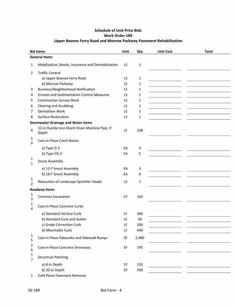
Schedule of Unit Price Bids Work Order 189
Upper Boones Ferry Road and Monroe Parkway Pavement Rehabilitation
Bid Items Unit Qty Unit Cost Total
General Items
1 Mobilization, Bonds, Insurance and Demobilization LS 1
2 Traffic Control
a) Upper Boones Ferry Road LS 1
b) Monroe Parkway LS 1
3 Business/Neighborhood Notification LS 1
4 Erosion and Sedimentation Control Measures LS 1
5 Construction Survey Work LS 1
6 Clearing and Grubbing LS 1
7 Demolition Work LS 1
8 Surface Restoration LS 1
Stormwater Drainage and Water Items
9 12‐in Ductile Iron Storm Drain Mainline Pipe, 5' Depth
LF 238
10
Cast‐in‐Place Catch Basins
a) Type G‐2 EA 4
b) Type CG‐2 EA 5
11
Snout Assembly
a) 12‐F Snout Assembly EA 3
b) 18‐F Snout Assembly EA 6
12
Relocation of Landscape Sprinkler Heads LS 1
Roadway Items 13
Common Excavation CY 150
14
Cast‐in‐Place Concrete Curbs
a) Standard Vertical Curb LF 340
b) Standard Curb and Gutter LF 50
c) Grade Correction Curb LF 330
d) Mountable Curb LF 440
15
Cast‐in‐Place Sidewalks and Sidewalk Ramps SF 2,480
16
Cast‐in‐Place Concrete Driveways SF 195
17
Structrual Patching
a) 8‐in Depth SY 135
b) 20‐in Depth SY 350
1 Cold Plane Pavement Removal

16‐189 Bid Form ‐ 5
8
a) 0‐2‐in Depth SY 400
b) 4‐5‐in Depth SY 500
c) 4‐in Depth SY 18,800
d) 5‐in Depth SY 4,600
19
Reconditioning Existing Roadway LS 1
20
Composite Grid Paving Interlayer SY 4,593
21
Asphalt Binder for Paving Interlayer TON
3.7
22
Asphalt Concrete ‐ Level 3, 1/2" Dense TON
7,000
23
Extra for Asphalt Street and Driveway Approaches SY 518
24
Replace City of Lake Oswego Water Valve Boxes EA 16
25
Adjust Miscellaneous Boxes EA 19
26
Adjust Manholes EA 2
27
Shoulder Crushed Rock TON
50
Pavement Marking Items
28
Pavement Markings ‐ Striping (Non‐Profile, Thermoplastic) a) ODOT Detail W LF 2,954
b) ODOT Detail WB LF 30
c) ODOT Detail W‐2 LF 4,537
d) ODOT Detail Y LF 29
e) ODOT Detail WD LF 80
f) ODOT Detail WD‐2 LF 40
g) ODOT Detail ND LF 12,003
h) ODOT Detail NPR LF 97
i) ODOT Detail NPL LF 107
29
Pavement Markings ‐ Legends and Bars (Thermoplastic) a) ODOT Detail YLD (Yield Line) EA 9
b) ODOT Detail LA (Left Turn Arrow) EA 15
c) ODOT Detail RA (Right Turn Arrow) EA 4
d) ODOT Detail CW‐SC (Crosswalk) SF 280
e) ODOT Detail S (Stop Bar ‐ 1' Wide) SF 85
f) ODOT Detail ON (Only) EA 4
g) ODOT Detail BS (Bike Lane ‐ Straight Arrow) EA 5
30
Pavement Markers
a) Bi‐Directional Blue Type 1 AR Markers EA 4
16‐189 Bid Form ‐ 6
31
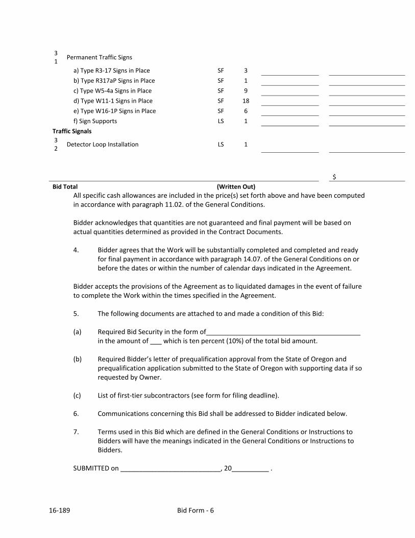
Permanent Traffic Signs
a) Type R3‐17 Signs in Place SF 3
b) Type R317aP Signs in Place SF 1
c) Type W5‐4a Signs in Place SF 9
d) Type W11‐1 Signs in Place SF 18
e) Type W16‐1P Signs in Place SF 6
f) Sign Supports LS 1
Traffic Signals
32
Detector Loop Installation LS 1
$
Bid Total (Written Out)
All specific cash allowances are included in the price(s) set forth above and have been computed in accordance with paragraph 11.02. of the General Conditions. Bidder acknowledges that quantities are not guaranteed and final payment will be based on actual quantities determined as provided in the Contract Documents.
4. Bidder agrees that the Work will be substantially completed and completed and ready
for final payment in accordance with paragraph 14.07. of the General Conditions on or before the dates or within the number of calendar days indicated in the Agreement.
Bidder accepts the provisions of the Agreement as to liquidated damages in the event of failure to complete the Work within the times specified in the Agreement.
5. The following documents are attached to and made a condition of this Bid:
(a) Required Bid Security in the form of
in the amount of which is ten percent (10%) of the total bid amount.
(b) Required Bidder’s letter of prequalification approval from the State of Oregon and prequalification application submitted to the State of Oregon with supporting data if so requested by Owner.
(c) List of first‐tier subcontractors (see form for filing deadline). 6. Communications concerning this Bid shall be addressed to Bidder indicated below. 7. Terms used in this Bid which are defined in the General Conditions or Instructions to
Bidders will have the meanings indicated in the General Conditions or Instructions to Bidders.
SUBMITTED on ___________________________, 20 .

16‐189 Bid Form ‐ 7
State Contractor License No. ______________________________________.

16‐189 Bid Form ‐ 8
Complete in black ink or by typewriter. If BIDDER is: An Individual Signature
(Individual's Name, Typed or Printed)
doing business as
Business address
Phone No. A Partnership Firm Name Signature
(Name of Partner, Typed or Printed)
Business address
Phone No.

16‐189 Bid Form ‐ 9
A Corporation Corporation Name Signature
(Officer's Name, Typed or Printed)
(Title)
(State of Incorporation)
Attest (Secretary's Signature)
Business address
Phone No. Date of Qualification to do business A Joint Venture Joint Venture Name Signature
(Name of Person Signing, Typed or Printed)
(Title)
(Address for Official Business)
(Phone Number for Official Business)
(Each joint venturer must sign. The manner of signing for each individual, partnership and corporation that is a party to the joint venture should be in the manner indicated above).

FIRST‐TIER SUBCONTRACTOR DISCLOSURE FORM (OAR 137‐040‐0017)
Bids which are submitted by Bid Closing, but for which a required disclosure submittal has not been made by the specified Disclosure Deadline, are not responsive and shall not be considered for Contract award
AGENCY SUPPLIED INFORMATION:
PROJECT NAME: WO 189 – Upper Boones Ferry Road and Monroe Parkway Pavement Rehabilitation
BID #: BID CLOSING: Date: June 21, 2016 Time: 2:00 AM PM
REQUIRED DISCLOSURE DEADLINE: Date: June 21, 2016 Time: 4:00 AM PM
Deliver Form To (Agency): City of Lake Oswego
Designated Recipient (Person): Crystal M. Shum, PE Phone #: 503.697.7420
Agency’s Address: 380 A Avenue, P. O. Box 369, Lake Oswego, Oregon 97034 INSTRUCTIONS: The contracting agency will insert "N/A" above if the contract value is not anticipated to exceed $100,000. Otherwise this form must be submitted either with the bid or within two (2) working hours after the advertised bid closing date and time; but no later than the DISCLOSURE DEADLINE stated above. Unless otherwise stated in the solicitation, this document shall not be submitted by facsimile. It is the responsibility of bidders to submit this disclosure form and any additional sheets, with the bid number and project name clearly marked, at the location indicated by the specified disclosure deadline. See “Instructions to Bidders”. List below the Name, Category of Work and Dollar Value for each first‐tier subcontractor that would be furnishing labor, or labor and material, for which disclosure is required. Enter the word "NONE" if there are no first‐tier subcontractors subject to disclosure. ATTACH ADDITIONAL SHEETS IF NECESSARY. BIDDER DISCLOSURE: SUBCONTRACTOR NAME CATEGORY OF WORK DOLLAR VALUE
1.
2.
3.
4.
5.
6. The above listed first‐tier subcontractor(s) are providing labor, or labor and material, with a Dollar Value equal to or greater than:
a) 5% of the total Contract Price, but at least $15,000. [If the Dollar Value is less than $15,000 do not list the subcontractor above.] or b) $350,000 regardless of the percentage of the total Contract Price.
Form Submitted By (Bidder Name): _________________________________________________ Contact Name: ___________________________________ Phone #: _______________________
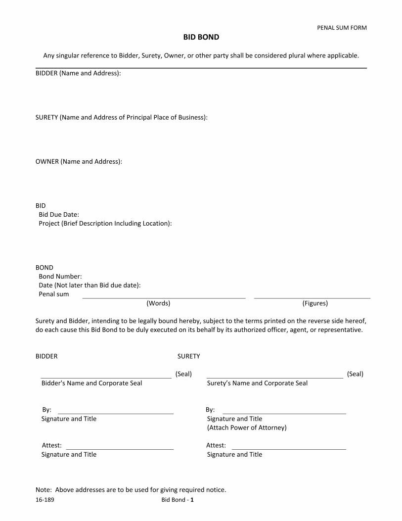
PENAL SUM FORM
16‐189 Bid Bond ‐ 1
BID BOND
Any singular reference to Bidder, Surety, Owner, or other party shall be considered plural where applicable.
BIDDER (Name and Address): SURETY (Name and Address of Principal Place of Business): OWNER (Name and Address): BID Bid Due Date: Project (Brief Description Including Location): BOND Bond Number: Date (Not later than Bid due date):
Penal sum
(Words) (Figures) Surety and Bidder, intending to be legally bound hereby, subject to the terms printed on the reverse side hereof, do each cause this Bid Bond to be duly executed on its behalf by its authorized officer, agent, or representative. BIDDER SURETY
(Seal) (Seal)
Bidder's Name and Corporate Seal Surety’s Name and Corporate Seal By: By:
Signature and Title Signature and Title (Attach Power of Attorney) Attest: Attest:
Signature and Title Signature and Title Note: Above addresses are to be used for giving required notice.
PENAL SUM FORM
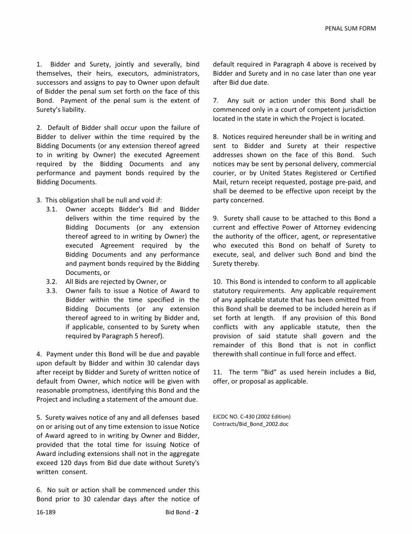
16‐189 Bid Bond ‐ 2
1. Bidder and Surety, jointly and severally, bind themselves, their heirs, executors, administrators, successors and assigns to pay to Owner upon default of Bidder the penal sum set forth on the face of this Bond. Payment of the penal sum is the extent of Surety’s liability. 2. Default of Bidder shall occur upon the failure of Bidder to deliver within the time required by the Bidding Documents (or any extension thereof agreed to in writing by Owner) the executed Agreement required by the Bidding Documents and any performance and payment bonds required by the Bidding Documents. 3. This obligation shall be null and void if:
3.1. Owner accepts Bidder's Bid and Bidder delivers within the time required by the Bidding Documents (or any extension thereof agreed to in writing by Owner) the executed Agreement required by the Bidding Documents and any performance and payment bonds required by the Bidding Documents, or
3.2. All Bids are rejected by Owner, or 3.3. Owner fails to issue a Notice of Award to
Bidder within the time specified in the Bidding Documents (or any extension thereof agreed to in writing by Bidder and, if applicable, consented to by Surety when required by Paragraph 5 hereof).
4. Payment under this Bond will be due and payable upon default by Bidder and within 30 calendar days after receipt by Bidder and Surety of written notice of default from Owner, which notice will be given with reasonable promptness, identifying this Bond and the Project and including a statement of the amount due. 5. Surety waives notice of any and all defenses based on or arising out of any time extension to issue Notice of Award agreed to in writing by Owner and Bidder, provided that the total time for issuing Notice of Award including extensions shall not in the aggregate exceed 120 days from Bid due date without Surety's written consent. 6. No suit or action shall be commenced under this Bond prior to 30 calendar days after the notice of
default required in Paragraph 4 above is received by Bidder and Surety and in no case later than one year after Bid due date. 7. Any suit or action under this Bond shall be commenced only in a court of competent jurisdiction located in the state in which the Project is located. 8. Notices required hereunder shall be in writing and sent to Bidder and Surety at their respective addresses shown on the face of this Bond. Such notices may be sent by personal delivery, commercial courier, or by United States Registered or Certified Mail, return receipt requested, postage pre‐paid, and shall be deemed to be effective upon receipt by the party concerned. 9. Surety shall cause to be attached to this Bond a current and effective Power of Attorney evidencing the authority of the officer, agent, or representative who executed this Bond on behalf of Surety to execute, seal, and deliver such Bond and bind the Surety thereby. 10. This Bond is intended to conform to all applicable statutory requirements. Any applicable requirement of any applicable statute that has been omitted from this Bond shall be deemed to be included herein as if set forth at length. If any provision of this Bond conflicts with any applicable statute, then the provision of said statute shall govern and the remainder of this Bond that is not in conflict therewith shall continue in full force and effect. 11. The term "Bid" as used herein includes a Bid, offer, or proposal as applicable. EJCDC NO. C‐430 (2002 Edition) Contracts/Bid_Bond_2002.doc


Page 1
WO 189
CITY OF LAKE OSWEGO
PUBLIC WORKS / PUBLIC IMPROVEMENT FOR PUBLIC IMPROVEMENT
(Greater than $50,000 / with General and Supplementary Conditions)
Contractor: Date of Contract: Mailing Address:
Date of Substantial Completion:
Date of Final Completion Project No.: WO 189 Contract Amount: Project:
Upper Boones Ferry Road and Monroe Parkway Pavement Rehabilitation
WITNESSETH: Contractor and the City of Lake Oswego, a municipal corporation, (“Owner”) mutually covenant and agree to and with each other as follows: 1. WORK / PROJECT 1.1 General Description of Work. The Work is generally described as follows:
The Scope of Work consists of pavement reconstruction, sidewalk and curb ramp construction/reconstruction, catch basin replacements, pavement marking and marker installation, and signal loop installation for Upper Boones Ferry Road and Monroe Parkway.
The Work is part of the above named “Project”, if stated above. 1.2 Project. The project for which the Work under the Contract Documents may be a part is referenced above.

Page 2
WO 189
2. CLASSIFICATION OF WORK / CONTRACT DOCUMENTS 2.1 Classification of Work. This Work is classified as: Applicable classification(s)
Classification Description of Classification
_____X______ (Note: Public Work and Public Improvement are not mutually exclusive; a public impvt contract is frequently also a public works contract).
Public Work Construction ‐ includes the initial building of structures and roads. Reconstruction ‐ includes the restoration of existing buildings and the restoration, rebuilding or resurfacing of existing roads (includes emergency work). Major Renovation ‐ includes any remodeling or alteration of existing structures or roads (includes emergency work). Painting of structure or building. General Maintenance / Demolition –Only if part of construction or major renovation project
______X_______
Public Improvement Construction, reconstruction or major renovation on real property, not including emergency work, or ordinary repair or maintenance necessary to preserve a public improvement.
_______________
Service Contract Relating to Public Improvement Project
General Maintenance necessary to preserve a public improvement (not part of construction or renovation). Demolition – Only if not part of construction or renovation).
2.2 Contract Documents. The Contract between the parties includes all of the following documents, and any conflicts shall be resolved in the following priority Classification of Work Documents
(* indicate documents attached; otherwise incorporated by reference)
Applicable to all Classifications of Work
This Contract, addenda*, Proposal / Bid*; Specifications and Drawings (including Written Amendments)*
Public Improvement Lake Oswego Public Improvement Contract Provisions (with General or Supplemental Conditions)*; Notice to Proceed; Bonds (if required) [Public Work documents listed below are also included.]
Public Work Lake Oswego Public Works Contract Provisions (with General or Supplemental Conditions) (includes Prevailing Rate Of Wage)*; Notice to Proceed; Change Orders and ENGINEER’s written interpretations and clarifications issued on or after the Date of Contract; Post Bid documentation submitted prior to the Notice of Award*
Service Contract Related to Public Improvement
Lake Oswego Standard Public Contract Provisions*
Note: Shop Drawing submittals approved pursuant to paragraph 6.17 of the General Conditions and the reports and drawings referred to in paragraph 4.02 of the General Conditions are not Contract Documents.
3. CONTRACT TIMES / LIQUIDATED DAMAGES 3.1 Dates of Substantial and Final Completion. The Work will be substantially completed on or before the Date of Substantial Completion stated above, and completed and ready for final payment in accordance with paragraph 14.07 of the General Conditions on or before the Date of Final Completion stated above.

Page 3
WO 189
3.2 Liquidated Damages. OWNER and CONTRACTOR recognize that time is of the essence of this Contract and OWNER will suffer financial loss if the Work is not completed within the times specified above, plus any extensions thereof allowed in accordance with Article 12 of the General Conditions. They also recognize the delays, expense and difficulties involved in proving the actual loss suffered by OWNER if the Work is not completed on time. Accordingly, instead of requiring any such proof, OWNER and CONTRACTOR agree that as liquidated damages for delay (but not as a penalty) CONTRACTOR shall pay OWNER Five Hundred and 00/100 Dollars ($500) for each day that expires after the time specified for Substantial Completion until the Work is substantially complete. After Substantial Completion, if CONTRACTOR shall neglect, refuse or fail to complete the remaining Work within the time specified for completion and readiness for final payment or any proper extension thereof granted by OWNER, CONTRACTOR shall pay OWNER Five Hundred and 00/100 Dollars ($500) for each day that expires after the time specified for Final Completion.
4. CONTRACT AMOUNT. No payment shall be due to the Contractor until the Contractor has completed and submitted to the City’s Finance Department the IRS Form W‐9 Request for Taxpayer Identification and Certification (http://www.irs.gov/pub/irs‐pdf/fw9.pdf). The City prefers to pay contractors by electronic fund transfer; the contractor may submit the EFT agreement (http://tinyurl.com/LO‐EFT) to the City’s Finance Department. OWNER agrees to pay, and CONTRACTOR agrees to accept, in full payment for completion of the Work in accordance with the Contract Documents, the Contract Amount stated above, as defined in 1.01.A.13 of the General Conditions; provided however, estimated quantities are not guaranteed, and determinations of actual quantities and classification are to be made by ENGINEER named above, if applicable, or Owner’s Project Manager, as provided in paragraph 9.08 of the General Conditions. Unit prices have been computed as provided in paragraph 11.03 of the General Conditions.
CONTRACTOR By:__________________________ Name:________________________ Title: _________________________ Date: _________________________ Check one: Sole Proprietor ______ Partnership ______ Corporation ______ Limited Liability Company ________ Limited Liability Partnership ________ Other: _________________ ________ Domicile, if other than Oregon: ________
Ver. 1412
CITY OF LAKE OSWEGO ____________________________ Scott Lazenby, City Manager Date: ______________________ Public Contracting Officer 380 A Avenue P.O. Box 369 Lake Oswego, OR 97034 Date Authorized by Council, if applicable: _______________________________.
APPROVED AS TO FORM:
_________________________ Evan P. Boone, Deputy City Attorney

LAKE OSWEGO PUBLIC IMPROVEMENTS CONTRACT PROVISIONS (01/09) (with General and Supplemental Conditions)
Page 1 – Lake Oswego Public Improvement Contract Provisions
The following Public Improvement Contract Provisions are made a part of the Contract between Owner and Contractor.
CONTRACTOR’S REPRESENTATIONS Contractor: 1. Has examined and carefully studied the Contract Documents and the other related data identified in the Bidding Documents. .2. Has visited the Site and become familiar with and is satisfied as to the general, local and Site conditions that may affect cost, progress, performance or furnishing of the Work. 3. Has carefully studied all: (1) reports of explorations and tests of subsurface conditions at or contiguous to the Site and all drawings of physical conditions in or relating to existing surface or subsurface structures at or contiguous to the Site (except Underground Facilities) which have been identified in the Supplementary Conditions as provided in paragraph 4.02. of the General Conditions and (2) reports and drawings of a Hazardous Environmental Condition, if any, at the Site which have been identified in the Supplementary Conditions as provided in paragraph 4.06 of the General Conditions. 4. Has obtained and carefully studied (or assumes responsibility for having done so) all additional supplementary examinations, investigations, explorations, tests, studies and data concerning conditions (surface, subsurface and Underground Facilities) at or contiguous to the Site which may affect cost, progress, performance or furnishing of the Work or which relate to any aspect of the means, methods, techniques, sequences and procedures of construction to be employed by Contractor, including applying the specific means, methods, techniques, sequences and procedures, if any, expressly required by the Contract Documents to be employed by Contractor and safety precautions and programs incident thereto. 5. Does not consider that any further examinations, investigations, explorations, tests, studies or data are necessary for the performance of the Work at the Contract Amount, within the Contract Times and in accordance with the other terms and conditions of the Contract Documents. 6. Is aware of the general nature of Work to be performed by Owner and others at the Site that relates to the Work as indicated in the Contract Documents. 7. Contractor has correlated the information known to Contractor, information and observations obtained from visits to the Site, reports and drawings identified in the Contract Documents and all additional examinations, investigations, explorations, tests, studies and data with the Contract Documents. 8. Has given Engineer written notice of all conflicts, errors, ambiguities or discrepancies that Contractor has discovered in the Contract Documents and the written resolution thereof by Engineer is acceptable to Contractor. 9. Agrees that the Contract Documents are generally sufficient to indicate and convey understanding of all terms and conditions for performance and furnishing of the Work.
PROGRESS PAYMENTS Except the extent otherwise provided in the General or Supplemental Conditions, Contractor shall submit Applications for Payment in accordance with the following:
1. Progress Payments: Retainage. Owner shall make monthly progress payments on account of the Contract Price on the basis of Contractor’s Applications for Payment as recommended by Engineer, during construction as provided in paragraphs 1.1 and 1.2 below. Payment shall be tendered, when due, in a manner consistent with the Owner’s Finance Department’s accounts payable check run cycle in place at the time payment is due. All such payments will be measured by the schedule of values established in paragraph 2.07.A of the General Conditions (and in the case of Unit Price Work based on the number of units completed) or, in the event there is no schedule of values, as provided in the General Requirements. 1.1. Prior to Substantial Completion, progress payments will be made in an amount equal to the percentage indicated below, but, in each case, less the aggregate of payments previously made and less such amounts as Engineer shall determine, or Owner may withhold, in accordance with paragraph 14.02 of the General Conditions: 95% of Work completed (with the balance being retainage). If Work has been 50% completed as determined by Engineer, and if the character and progress of the Work have been satisfactory to Owner and Engineer, Owner, on recommendation of Engineer, may determine that as long as the character and progress of the Work remain satisfactory to them, there will be no additional retainage on account of Work completed, in which case the remaining progress payments prior to Substantial Completion will be in an amount equal to 100% of the Work completed less the aggregate of payments previously made; and 95% (with the balance being retainage) of cost of materials and equipment not incorporated in the Work (but delivered, suitably stored and accompanied by documentation satisfactory to Owner as provided in paragraph 14.02 of the General Conditions). 1.2. Upon Substantial Completion, Owner shall pay an amount sufficient to increase total payments to Contractor to 100% of the work completed, less such amounts as Engineer shall determine, or Owner may withhold, in accordance with paragraph 14.02.B.5 of the General Conditions and less 100% of Engineer’s estimate of the value of the Work to be completed or corrected as shown on the tentative list of items to be completed or corrected attached to the Certificate of Substantial Completion. 1.3. As provided by ORS 279C.570(7), 5% of the monthly progress payments due to Contractor shall be retained by the Owner until final payment is paid at the completion of the Project, unless the Contractor complies with ORS 279C.560 and provides required security to reduce the retainage. 2. Final Payment. Upon final completion and acceptance of the Work in accordance with paragraph 14.07 of the General Conditions, Owner shall pay the remainder of the Contract Price as recommended by Engineer as provided in said paragraph 14.07. 3. Interest. In accordance with ORS 279C.570, the rate of interest charged to the Owner on the amount due shall equal three times the discount rate on 90‐day commercial paper in effect at the Federal Reserve Bank in the Federal Reserve district that includes Oregon on the date that is 30 days after receipt of the invoice from the contractor or 15 days after the payment is approved by the Owner, whichever is the earlier

LAKE OSWEGO PUBLIC IMPROVEMENTS CONTRACT PROVISIONS (01/09) (with General and Supplemental Conditions)
Page 2 – Lake Oswego Public Improvement Contract Provisions
date, but the rate of interest shall not exceed 30 percent. Payment of interest may be postponed when payment on the principal is delayed because of disagreement between the Owner and the Contractor.
CONTRACTOR/SUBCONTRACTOR PAYMENT DISPUTES
The Contractor is required to include in each subcontract for property or services entered into by the Contractor and a first‐tier subcontractor, including a material supplier, for the purpose of performing this construction contract: 1. A payment clause that obligates the Contractor to pay the first‐tier subcontractor for satisfactory performance under its subcontract within 10 days out of such amounts as are paid to the Contractor by the public contracting agency under such contract; and 2. An interest penalty clause that obligates the Contractor, if payment is not made within 30 days after receipt of payment from the Owner, to pay to the first‐tier subcontractor an interest penalty on amounts due in the case of each payment not made in accordance with the payment clause included in the subcontract pursuant to paragraph (a) of this subsection. A contractor or first‐tier subcontractor shall not be obligated to pay an interest penalty if the only reason that the contractor or first‐tier subcontractor did not make payment when payment was due is that the contractor or first‐tier subcontractor did not receive payment from the Owner or contractor when payment was due. The interest penalty shall be: a. For the period beginning on the day after the required payment date and ending on the date on which payment of the amount is due made; and b. Computed at the rate specified in 279C.570 (2). The Contractor is further required to include in each of its subcontracts, for the purpose of performance of such contract condition, a provision requiring the first‐tier subcontractor to include a payment clause and an interest penalty clause conforming to the standards of this section and require each of its subcontractors to include such clauses in their subcontracts with each lower‐tier subcontractor or supplier. The Contractor shall not request payment of any amount withheld or retained in accordance with ORS 279C.560(6) until such time as the Contractor has determined and certified to the Owner that the subcontractor is entitled to the payment of such amount. A dispute between the Contractor and a first‐tier subcontractor relating to the amount or entitlement of a subcontractor to a payment or a late payment interest penalty under a clause included in the subcontract pursuant to subsection (4) or (5) of ORS 279C.580 does not constitute a dispute to which the Owner is a party. The Owner shall not be included as a party in any administrative or judicial proceeding involving such a dispute.
ASSIGNMENT This contract is not assignable by the Contractor, either whole or in part, unless Contractor has obtained the prior written consent of the City. City and Contractor are the only parties to this Contract and are the only parties entitled to enforce its terms. Nothing in this Contract gives, is intended to give, or shall be construed to give or provide any enforceable benefit or right, whether directly, indirectly or otherwise, to third persons.
PAYMENT OF LABORERS AND DRUG TESTING PROGRAM
1. The Contractor shall, to the extent as may be required by Oregon law: a. Make payment promptly, as due, to all persons supplying to such Contractor labor or material for the prosecution of the work provided for this contract; b. Workers shall be paid not less than the applicable state or federal prevailing wage rate, whichever is higher. ORS 279C.830(1)(c); OAR 839‐025‐0020(3) c. Pay all contributions or amounts due the Industrial Accident Fund by the Contractor or subcontractors, if permitted, incurred in the performance of this contract; d. Not permit any lien or claim to be filed or prosecuted against the Owner on account of any labor or material furnished; and e. Pay to the Department of Revenue all sums withheld from employees pursuant to ORS 316.167. f. Demonstrate that an employee drug testing program is in place during the term of this Contract. 2. If the Contractor fails to pay for labor and services, the Owner may pay for them and withhold these amounts from payments to the Contractor. ORS 279C.515; OAR 839‐025‐0020(2)(a). 3. If the contractor or a first‐tier subcontractor fails, neglects or refuses to make payment to a person furnishing labor or materials within 30 days after receipt of payment from the Owner or a contractor, the contractor or first‐tier subcontractor shall owe the person the amount due plus interest charges commencing at the end of the 10‐day period that payment is due under ORS 279C.580(4) and ending upon final payment, unless payment is subject to a good faith dispute as defined in ORS 279C.580. The rate of interest charged to the contractor or first‐tier subcontractor on the amount due shall equal three times the discount rate on 90‐day commercial paper in effect at the Federal Reserve Bank in the Federal Reserve district that includes Oregon on the date that is 30 days after the date when payment was received from the Owner or from the contractor, but the rate of interest shall not exceed 30 percent. The amount of interest may not be waived. 4. If requested in writing by a first‐tier subcontractor, the contractor, within 10 calendar days after receiving the request, shall send to the first‐tier subcontractor a copy of that portion of any invoice, request for payment submitted to the public contracting agency or pay document provided by the public contracting agency to the contractor specifically related to any labor or materials supplied by the first‐tier subcontractor.

LAKE OSWEGO PUBLIC IMPROVEMENTS CONTRACT PROVISIONS (01/09) (with General and Supplemental Conditions)
Page 3 – Lake Oswego Public Improvement Contract Provisions
5. This contract and every contract related to this contract shall contain a clause or condition that, if the contractor or a subcontractor fails, neglects or refuses to make payment to a person furnishing labor or materials in connection with the this contract, the person may file a complaint with the Construction Contractors Board, unless payment is subject to a good faith dispute as defined in ORS 279C.580. 6. The payment of a claim in this manner shall not relieve the Contractor or the Contractor's surety, if any, from obligation with respect to any unpaid claims. PAYMENT FOR MEDICAL CARE AND PROVIDING WORKERS'
COMPENSATION The Contractor shall promptly, as due, make payment to any person, co‐partnership, association or corporation, furnishing medical, surgical and hospital care or other needed care and attention, incident to sickness or injury, to the employees of such Contractor, of all sums which the Contractor agrees to pay for such services and all moneys and sums which the Contractor collected or deducted from the wages of employees pursuant to any law, contract or agreement for the purpose of providing or paying for such service. ORS 279C.530; OAR 839‐025‐0020(2)(d). The Contractor, its subcontractors, if any, and all employers working under this contract, are subject employers under the Oregon Workers' Compensation Law and shall comply with ORS 656.017, which requires them to provide workers' compensation coverage for all their subject workers.
HOURS OF LABOR For those employees of Contractor that are covered or subject to Oregon employment laws, no person shall be employed for more than ten hours in any one day, or 40 hours in any one week, except in cases of necessity, emergency or where the Owner absolutely requires it, and in such cases, the laborer shall be paid at least time and a half pay: 1. for all overtime in excess of eight hours a day or 40 hours in any one week when the work week is five consecutive days, Monday through Friday; or 2. for all overtime in excess of ten hours a day or 40 hours in any one week when the work week is four consecutive days, Monday through Friday; or 3. for work performed on Saturday and on any legal holidays specified in ORS 279C.540. For those employees of Contractor that are covered or subject to Oregon employment laws, Contractor must, pursuant to ORS 279C.520(1)(b), give notice to employees who perform work on this Contract, either at the time of hire or before commencement of work on the contract, or by posting a notice in a location frequented by employees, of the number of hours per day and days per week that the employees may be required to work.
TIME LIMITATION ON CLAIM FOR OVERTIME To the extent any of Contractor’s employees are covered by the Oregon employment laws, such covered worker employed by the Contractor shall be foreclosed from the right to collect for any overtime under this contract unless a claim for payment is filed with the Contractor within 90 days from the completion of the contract, providing the Contractor has:
1. Caused a circular clearly printed in blackface pica type and containing a copy of this section to be posted in a prominent place alongside the door of the timekeeper's office or in a similar place which is readily available and freely visible to any or all workers employed on the work, and 2. Maintained such circular continuously posted from the inception to the completion of the contract on which workers are or have been employed.
COMPLIANCE WITH LAWS The provisions of ORS 279C.570 and ORS 279C.600 ‐ 279C.620 for public contracting are incorporated by this reference as though fully set forth herein. In addition, the Contractor shall comply with all Federal, State and local laws and ordinances applicable to the Work to be done under this Contract. The Contractor shall comply with all applicable federal, state, and local laws, rules, and regulations on nondiscrimination in employment because of race, color, ancestry, national origin, religion, sex, marital status, age, medical condition, or disability.
RECYCLING DEMOLITION MATERIALS If this Contract calls for demolition work, the Contractor shall salvage or recycle construction and demolition debris, if feasible and cost‐effective.
LANDSCAPE MAINTENANCE If this contract is for lawn and landscape, the contractor shall compost or mulch yard waste material at an approved site, if feasible and cost‐effective. Ver. 09

LAKE OSWEGO PUBLIC WORKS CONTRACT PROVISIONS (11/07) (with General and Supplemental Conditions)
Page 1 – Lake Oswego Public Works Contract Provisions
The following Public Works Contract Provisions are made a part of the Contract between Owner and Contractor. RELATIONSHIP WITH PUBLIC IMPROVEMENT CONTRACT
PROVISIONS If the Contract also contains Lake Oswego Public Improvement Contract Provisions, in the event these Public Works Contract Provisions address the same matter as the Lake Oswego Public Improvement Contract Provisions, the Lake Oswego Public Improvement Contract Provisions shall control.
PUBLIC WORKS BONDS FOR CONTRACTS $100,000 OR
ABOVE If the original Contract Amount is $100,000 or greater, or if the Contract Amount is amended to a Contract Amount $100,000 or greater, and unless otherwise exempt under ORS 279C.836(4), (7) – (9), the Contractor shall file a public works bond with the Oregon Construction Contractors Board before starting or continuing work on the project. Further, the Contractor shall then include in every subcontract a provision requiring the subcontractor to have a public works bond filed with the Oregon Construction Contractors Board before starting work, or if the Contract Amount is amended to $100,000 or above, before continuing work on the project. ORS 279C.830(3)(a,b)
PREVAILING RATE OF WAGE 1. The hourly rate of wage to be paid by any contractor or subcontractor to workers upon all public works where the Project Amount price exceeds $50,000 shall be not less than the prevailing rate of wage for an hour's work in the same trade or occupation in the locality where such labor is performed as determined by the Commissioner of the Bureau of Labor and Industries, unless the project is subject to both the Oregon Prevailing Wage Law and the federal Davis‐Bacon Act, in which event the payment to the worker shall be the higher of the state or federal rates. See applicable state rates: http://www.boli.state.or.us/BOLI/WHD/PWR/pwr_book.shtml; and projects that are also subject to federal prevailing wage laws, see www.wdol.gov/ for federal wage rates. 2. Any contract between Contractor and a subcontractor shall contain a provision that shall require the Subcontractor to pay workers not less than the higher applicable specified minimum hourly rate of wage. 3. The Contractor and subcontractor(s), if any, shall keep the prevailing wage rates for this project posted in a conspicuous and accessible place in or about the project. 4. If the Contractor or subcontractor also provides for or contributes to a health and welfare plan or a pension plan, or both, for its employees on the project, it shall post notice describing such plans in a conspicuous and accessible place in or about the project. The notice shall contain information on how and where to make claims and where to obtain further information.
5. The Contractor and every subcontractor shall file certified statements with the Owner in writing in form prescribed by the Commissioner of the Bureau of Labor and Industries, certifying the hourly rate of wage paid each worker which the Contractor or the subcontractor has employed upon such public work, and further certifying that no worker employed upon such public work has been paid less than the prevailing rate of wage or less than the minimum hourly rate of wage specified in the Contract, which certificate and statement shall be verified by the oath of the Contractor or the Contractor's surety or subcontractor or subcontractor's surety that the Contractor or subcontractor has read such statement and certificate and knows the contents thereof and that the same is true to the Contractor or subcontractor's knowledge. The certified statements shall set out accurately and completely the payroll records for the prior week including the name and address of each worker, the worker's correct classification, rate of pay, daily and weekly number of hours worked, deductions made and actual wages paid. The certified statement shall be delivered or mailed by the Contractor or subcontractor to the Owner within the time required by ORS 279C.845 and OAR 839‐016‐0010. If Contractor fails to file the certified statement, the OWNER shall, pursuant to Oregon law, shall withhold 25% of amounts owed to contractors, in addition to any retainage withholding. Contractor shall, similarly, withhold 25% of amounts owed to subcontractors if the subcontractor fails to file the certified statement. 6. The Contractor or subcontractor shall preserve the certified statements for a period of three years from the date of completion of the contract.

16‐189 Performance Bond ‐ 1
PERFORMANCE BOND
Any singular reference to Contractor, Surety, Owner, or other party shall be considered plural where applicable.
CONTRACTOR (Name and Address): SURETY (Name and Address of Principal Place of Business): OWNER (Name and Address): CONTRACT Date: Amount: Description (Name and Location): BOND Bond Number: Date (Not earlier than Contract Date): Amount: Modifications to this Bond Form: Surety and Contractor, intending to be legally bound hereby, subject to the terms printed on the reverse side hereof, do each cause this Performance Bond to be duly executed on its behalf by its authorized officer, agent, or representative. CONTRACTOR AS PRINCIPAL SURETY Company: Signature: (Seal) (Seal)
Name and Title: Surety’s Name and Corporate Seal By:
Signature and Title (Attach Power of Attorney) (Space is provided below for signatures of additional parties, if required.)
Attest:
Signature and Title CONTRACTOR AS PRINCIPAL SURETY Company: Signature: (Seal) (Seal)
Name and Title: Surety’s Name and Corporate Seal By:
Signature and Title (Attach Power of Attorney) Attest:
Signature and Title:
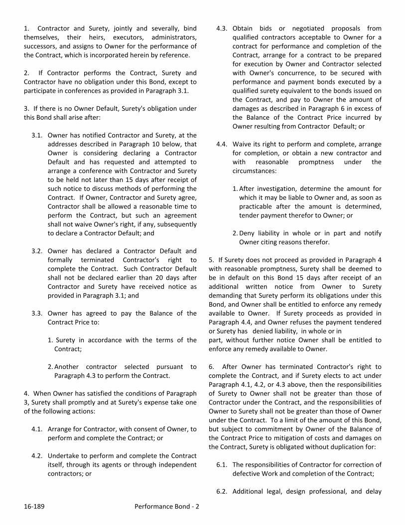
16‐189 Performance Bond ‐ 2
1. Contractor and Surety, jointly and severally, bind themselves, their heirs, executors, administrators, successors, and assigns to Owner for the performance of the Contract, which is incorporated herein by reference. 2. If Contractor performs the Contract, Surety and Contractor have no obligation under this Bond, except to participate in conferences as provided in Paragraph 3.1. 3. If there is no Owner Default, Surety's obligation under this Bond shall arise after:
3.1. Owner has notified Contractor and Surety, at the addresses described in Paragraph 10 below, that Owner is considering declaring a Contractor Default and has requested and attempted to arrange a conference with Contractor and Surety to be held not later than 15 days after receipt of such notice to discuss methods of performing the Contract. If Owner, Contractor and Surety agree, Contractor shall be allowed a reasonable time to perform the Contract, but such an agreement shall not waive Owner's right, if any, subsequently to declare a Contractor Default; and
3.2. Owner has declared a Contractor Default and
formally terminated Contractor's right to complete the Contract. Such Contractor Default shall not be declared earlier than 20 days after Contractor and Surety have received notice as provided in Paragraph 3.1; and
3.3. Owner has agreed to pay the Balance of the
Contract Price to:
1. Surety in accordance with the terms of the Contract;
2. Another contractor selected pursuant to Paragraph 4.3 to perform the Contract.
4. When Owner has satisfied the conditions of Paragraph 3, Surety shall promptly and at Surety's expense take one of the following actions:
4.1. Arrange for Contractor, with consent of Owner, to perform and complete the Contract; or
4.2. Undertake to perform and complete the Contract
itself, through its agents or through independent contractors; or
4.3. Obtain bids or negotiated proposals from qualified contractors acceptable to Owner for a contract for performance and completion of the Contract, arrange for a contract to be prepared for execution by Owner and Contractor selected with Owner's concurrence, to be secured with performance and payment bonds executed by a qualified surety equivalent to the bonds issued on the Contract, and pay to Owner the amount of damages as described in Paragraph 6 in excess of the Balance of the Contract Price incurred by Owner resulting from Contractor Default; or
4.4. Waive its right to perform and complete, arrange
for completion, or obtain a new contractor and with reasonable promptness under the circumstances:
1. After investigation, determine the amount for which it may be liable to Owner and, as soon as practicable after the amount is determined, tender payment therefor to Owner; or
2. Deny liability in whole or in part and notify Owner citing reasons therefor.
5. If Surety does not proceed as provided in Paragraph 4 with reasonable promptness, Surety shall be deemed to be in default on this Bond 15 days after receipt of an additional written notice from Owner to Surety demanding that Surety perform its obligations under this Bond, and Owner shall be entitled to enforce any remedy available to Owner. If Surety proceeds as provided in Paragraph 4.4, and Owner refuses the payment tendered or Surety has denied liability, in whole or in part, without further notice Owner shall be entitled to enforce any remedy available to Owner. 6. After Owner has terminated Contractor's right to complete the Contract, and if Surety elects to act under Paragraph 4.1, 4.2, or 4.3 above, then the responsibilities of Surety to Owner shall not be greater than those of Contractor under the Contract, and the responsibilities of Owner to Surety shall not be greater than those of Owner under the Contract. To a limit of the amount of this Bond, but subject to commitment by Owner of the Balance of the Contract Price to mitigation of costs and damages on the Contract, Surety is obligated without duplication for:
6.1. The responsibilities of Contractor for correction of defective Work and completion of the Contract;
6.2. Additional legal, design professional, and delay

16‐189 Performance Bond ‐ 3
costs resulting from Contractor's Default, and resulting from the actions or failure to act of Surety under Paragraph 4; and
6.3. Liquidated damages, or if no liquidated damages
are specified in the Contract, actual damages caused by delayed performance or non‐performance of Contractor.
7. Surety shall not be liable to Owner or others for obligations of Contractor that are unrelated to the Contract, and the Balance of the Contract Price shall not be reduced or set off on account of any such unrelated obligations. No right of action shall accrue on this Bond to any person or entity other than Owner or its heirs, executors, administrators, or successors. 8. Surety hereby waives notice of any change, including changes of time, to Contract or to related subcontracts, purchase orders, and other obligations. 9. Any proceeding, legal or equitable, under this Bond may be instituted in any court of competent jurisdiction in the location in which the Work or part of the Work is located and shall be instituted within two years after Contractor Default or within two years after Contractor ceased working or within two years after Surety refuses or fails to perform its obligations under this Bond, whichever occurs first. If the provisions of this paragraph are void or prohibited by law, the minimum period of limitation available to sureties as a defense in the jurisdiction of the suit shall be applicable. 10. Notice to Surety, Owner, or Contractor shall be mailed or delivered to the address shown on the signature page.
11. When this Bond has been furnished to comply with a statutory requirement in the location where the Contract was to be performed, any provision in this Bond conflicting with said statutory requirement shall be deemed deleted herefrom and provisions conforming to such statutory requirement shall be deemed incorporated herein. The intent is that this Bond shall be construed as a statutory bond and not as a common law bond. 12. Definitions.
12.1 Balance of the Contract Price: The total amount payable by Owner to Contractor under the Contract after all proper adjustments have been made, including allowance to Contractor of any amounts received or to be received by Owner in settlement of insurance or other Claims for damages to which Contractor is entitled, reduced by all valid and proper payments made to or on behalf of Contractor under the Contract.
12.2. Contract: The agreement between Owner and
Contractor identified on the signature page, including all Contract Documents and changes thereto.
12.3. Contractor Default: Failure of Contractor, which
has neither been remedied nor waived, to perform or otherwise to comply with the terms of the Contract.
12.4. Owner Default: Failure of Owner, which has
neither been remedied nor waived, to pay Contractor as required by the Contract or to perform and complete or comply with the other terms thereof.
FOR INFORMATION ONLY – Name, Address and Telephone Surety Agency or Broker Owner’s Representative (engineer or other party)
EJCDC No. C‐610 (2002 Edition) Contracts/2002/Performance_Bond_2002.doc

16‐189 Payment Bond ‐ 1
PAYMENT BOND
Any singular reference to Contractor, Surety, Owner, or other party shall be considered plural where applicable.
CONTRACTOR (Name and Address): SURETY (Name and Address of Principal Place of Business): OWNER (Name and Address): CONTRACT Date: Amount: Description (Name and Location): BOND Bond Number: Date (Not earlier than Contract Date): Amount: Modifications to this Bond Form: Surety and Contractor, intending to be legally bound hereby, subject to the terms printed on the reverse side hereof, do each cause this Payment Bond to be duly executed on its behalf by its authorized officer, agent, or representative. CONTRACTOR AS PRINCIPAL SURETY Company: Signature: (Seal) (Seal)
Name and Title: Surety’s Name and Corporate Seal By:
Signature and Title (Attach Power of Attorney) (Space is provided below for signatures of additional parties, if required.)
Attest:
Signature and Title CONTRACTOR AS PRINCIPAL SURETY Company: Signature: (Seal) (Seal)
Name and Title: Surety’s Name and Corporate Seal By:
Signature and Title (Attach Power of Attorney) Attest:
Signature and Title:

16‐189 Payment Bond ‐ 2
1. Contractor and Surety, jointly and severally, bind themselves, their heirs, executors, administrators, successors, and assigns to Owner to pay for labor, materials, and equipment furnished by Claimants for use in the performance of the Contract, which is incorporated herein by reference. 2. With respect to Owner, this obligation shall be null and void if Contractor: 2.1. Promptly makes payment, directly or indirectly, for
all sums due Claimants, and 2.2. Defends, indemnifies, and holds harmless Owner
from all claims, demands, liens, or suits alleging non‐payment by Contractor by any person or entity who furnished labor, materials, or equipment for use in the performance of the Contract, provided Owner has promptly notified Contractor and Surety (at the addresses described in Paragraph 12) of any claims, demands, liens, or suits and tendered defense of such claims, demands, liens, or suits to Contractor and Surety, and provided there is no Owner Default.
3. With respect to Claimants, this obligation shall be null and void if Contractor promptly makes payment, directly or indirectly, for all sums due. 4. Surety shall have no obligation to Claimants under this Bond until: 4.1. Claimants who are employed by or have a direct
contract with Contractor have given notice to Surety (at the addresses described in Paragraph 12) and sent a copy, or notice thereof, to Owner, stating that a claim is being made under this Bond and, with substantial accuracy, the amount of the claim.
4.2. Claimants who do not have a direct contract with
Contractor:
1. Have furnished written notice to Contractor and sent a copy, or notice thereof, to Owner, within 90 days after having last performed labor or last furnished materials or equipment included in the claim stating, with substantial accuracy, the amount of the claim and the name of the party to whom the materials or equipment were furnished or supplied, or for whom the labor was done or performed; and
2. Have either received a rejection in whole or in part from Contractor, or not received within 30 days of furnishing the above notice any communication from Contractor by which Contractor had indicated the claim will be paid directly or indirectly; and
3. Not having been paid within the above 30 days, have sent a written notice to Surety and sent a copy, or notice thereof, to Owner, stating that a claim is being made under this Bond and enclosing a copy of the previous written notice furnished to Contractor.
5. If a notice by a Claimant required by Paragraph 4 is provided by Owner to Contractor or to Surety, that is sufficient compliance. 6. When a Claimant has satisfied the conditions of Paragraph 4, the Surety shall promptly and at Surety's expense take the following actions: 6.1. Send an answer to that Claimant, with a copy to
Owner, within 45 days after receipt of the claim, stating the amounts that are undisputed and the basis for challenging any amounts that are disputed.
6.2. Pay or arrange for payment of any undisputed
amounts. 7. Surety's total obligation shall not exceed the amount of this Bond, and the amount of this Bond shall be credited for any payments made in good faith by Surety. 8. Amounts owed by Owner to Contractor under the Contract shall be used for the performance of the Contract and to satisfy claims, if any, under any performance bond. By Contractor furnishing and Owner accepting this Bond, they agree that all funds earned by Contractor in the performance of the Contract are dedicated to satisfy obligations of Contractor and Surety under this Bond, subject to Owner's priority to use the funds for the completion of the Work. 9. Surety shall not be liable to Owner, Claimants, or others for obligations of Contractor that are unrelated to the Contract. Owner shall not be liable for payment of any costs or expenses of any Claimant under this Bond, and shall have under this Bond no obligations to make

16‐189 Payment Bond ‐ 3
payments to, give notices on behalf of, or otherwise have obligations to Claimants under this Bond. 10. Surety hereby waives notice of any change, including changes of time, to the Contract or to related Subcontracts, purchase orders and other obligations. 11. No suit or action shall be commenced by a Claimant under this Bond other than in a court of competent jurisdiction in the location in which the Work or part of the Work is located or after the expiration of one year from the date (1) on which the Claimant gave the notice required by Paragraph 4.1 or Paragraph 4.2.3, or (2) on which the last labor or service was performed by anyone or the last materials or equipment were furnished by anyone under the Construction Contract, whichever of (1) or (2) first occurs. If the provisions of this paragraph are void or prohibited by law, the minimum period of limitation available to sureties as a defense in the jurisdiction of the suit shall be applicable. 12. Notice to Surety, Owner, or Contractor shall be mailed or delivered to the addresses shown on the signature page. Actual receipt of notice by Surety, Owner, or Contractor, however accomplished, shall be sufficient compliance as of the date received at the address shown on the signature page. 13. When this Bond has been furnished to comply with a statutory requirement in the location where the Contract was to be performed, any provision in this Bond conflicting with said statutory requirement shall be deemed deleted herefrom and provisions conforming to such statutory requirement shall be deemed incorporated herein. The intent is that this Bond shall be construed as a statutory Bond and not as a common law bond.
14. Upon request of any person or entity appearing to be a potential beneficiary of this Bond, Contractor shall promptly furnish a copy of this Bond or shall permit a copy to be made. 15. DEFINITIONS 15.1. Claimant: An individual or entity having a direct
contract with Contractor, or with a first‐tier subcontractor of Contractor, to furnish labor, materials, or equipment for use in the performance of the Contract. The intent of this Bond shall be to include without limitation in the terms "labor, materials or equipment" that part of water, gas, power, light, heat, oil, gasoline, telephone service, or rental equipment used in the Contract, architectural and engineering services required for performance of the Work of Contractor and Contractor's Subcontractors, and all other items for which a mechanic's lien may be asserted in the jurisdiction where the labor, materials, or equipment were furnished.
15.2. Contract: The agreement between Owner and
Contractor identified on the signature page, including all Contract Documents and changes thereto.
15.3. Owner Default: Failure of Owner, which has
neither been remedied nor waived, to pay Contractor as required by the Contract or to perform and complete or comply with the other terms thereof..
FOR INFORMATION ONLY – Name, Address and Telephone Surety Agency or Broker: Owner’s Representative (engineer or other party): EJCDC No. C‐615 (2002 Edition Contracts/Payment_Bond_2002.doc

16‐189 General Conditions ‐1
TABLE OF CONTENTS
Page ARTICLE 1 ‐ DEFINITIONS AND TERMINOLOGY ............................................................................................................................ 4 1.01 Defined Terms .......................................................................................................................................................... 4 1.02 Terminology ............................................................................................................................................................. 6
ARTICLE 2 ‐ PRELIMINARY MATTERS ............................................................................................................................................ 7 2.01 Delivery of Bonds and Evidence of Insurance ........................................................................................................... 7 2.02 Copies of Documents ................................................................................................................................................ 7 2.03 Commencement of Contract Times; Notice to Proceed ........................................................................................... 7 2.04 Starting the Work ..................................................................................................................................................... 7 2.05 Before Starting Construction .................................................................................................................................... 7 2.06 Preconstruction Conference ..................................................................................................................................... 7 2.07 Initial Acceptance of Schedules ................................................................................................................................ 7
ARTICLE 3 ‐ CONTRACT DOCUMENTS: INTENT, AMENDING, REUSE ........................................................................................... 8 3.01 Intent ........................................................................................................................................................................ 8 3.02 Reference Standards ................................................................................................................................................ 8 3.03 Reporting and Resolving Discrepancies ................................................................................................................... 8 3.04 Amending and Supplementing Contract Documents ............................................................................................... 9 3.05 Reuse of Documents ................................................................................................................................................. 9 3.06 Electronic Data ......................................................................................................................................................... 9
ARTICLE 4 ‐ AVAILABILITY OF LANDS; SUBSURFACE AND PHYSICAL CONDITIONS; HAZARDOUS ENVIRONMENTAL CONDITIONS; REFERENCE POINTS ............................................................................................................................................... 9 4.01 Availability of Lands ................................................................................................................................................. 9 4.02 Subsurface and Physical Conditions ....................................................................................................................... 10 4.03 Differing Subsurface or Physical Conditions ........................................................................................................... 10 4.04 Underground Facilities ........................................................................................................................................... 11 4.05 Reference Points .................................................................................................................................................... 11 4.06 Hazardous Environmental Condition at Site .......................................................................................................... 11
ARTICLE 5 ‐ BONDS AND INSURANCE ........................................................................................................................................ 13 5.01 Performance, Payment, and Other Bonds .............................................................................................................. 13 5.02 Licensed Sureties and Insurers ............................................................................................................................... 13 5.03 Certificates of Insurance ........................................................................................................................................ 13 5.04 Contractor’s Liability Insurance .............................................................................................................................. 13 5.05 Owner’s Liability Insurance .................................................................................................................................... 14 5.06 Property Insurance ................................................................................................................................................. 14 5.07 Waiver of Rights ..................................................................................................................................................... 15 5.08 Receipt and Application of Insurance Proceeds ..................................................................................................... 15 5.09 Acceptance of Bonds and Insurance; Option to Replace ........................................................................................ 16 5.10 Partial Utilization, Acknowledgment of Property Insurer ...................................................................................... 16
ARTICLE 6 ‐ CONTRACTOR’S RESPONSIBILITIES ......................................................................................................................... 16 6.01 Supervision and Superintendence .......................................................................................................................... 16 6.02 Labor; Working Hours ............................................................................................................................................ 16 6.03 Services, Materials, and Equipment ....................................................................................................................... 16 6.04 Progress Schedule .................................................................................................................................................. 17 6.05 Substitutes and “Or‐Equals”................................................................................................................................... 17 6.06 Concerning Subcontractors, Suppliers, and Others ................................................................................................ 18 6.07 Patent Fees and Royalties ...................................................................................................................................... 19 6.08 Permits ................................................................................................................................................................... 19 6.09 Laws and Regulations ............................................................................................................................................ 19 6.10 Taxes ...................................................................................................................................................................... 20 6.11 Use of Site and Other Areas ................................................................................................................................... 20 6.12 Record Documents ................................................................................................................................................. 20 6.13 Safety and Protection ............................................................................................................................................. 20

16‐189 General Conditions ‐2
6.14 Safety Representative ............................................................................................................................................ 21 6.15 Hazard Communication Programs ......................................................................................................................... 21 6.16 Emergencies ........................................................................................................................................................... 21 6.17 Shop Drawings and Samples .................................................................................................................................. 21 6.18 Continuing the Work .............................................................................................................................................. 22 6.19 Contractor’s General Warranty and Guarantee .................................................................................................... 22 6.20 Indemnification ...................................................................................................................................................... 23 6.21 Delegation of Professional Design Services ............................................................................................................ 23
ARTICLE 7 ‐ OTHER WORK AT THE SITE ...................................................................................................................................... 24 7.01 Related Work at Site .............................................................................................................................................. 24 7.02 Coordination .......................................................................................................................................................... 24 7.03 Legal Relationships ................................................................................................................................................ 24
ARTICLE 8 ‐ OWNER’S RESPONSIBILITIES ................................................................................................................................... 24 8.01 Communications to Contractor .............................................................................................................................. 24 8.02 Replacement of Engineer ....................................................................................................................................... 24 8.03 Furnish Data ........................................................................................................................................................... 24 8.04 Pay When Due ........................................................................................................................................................ 25 8.05 Lands and Easements; Reports and Tests .............................................................................................................. 25 8.06 Insurance ................................................................................................................................................................ 25 8.07 Change Orders ....................................................................................................................................................... 25 8.08 Inspections, Tests, and Approvals .......................................................................................................................... 25 8.09 Limitations on Owner’s Responsibilities ................................................................................................................. 25 8.10 Undisclosed Hazardous Environmental Condition ................................................................................................. 25 8.11 Evidence of Financial Arrangements ...................................................................................................................... 25
ARTICLE 9 ‐ ENGINEER’S STATUS DURING CONSTRUCTION ...................................................................................................... 25 9.01 Owner’s Representative ......................................................................................................................................... 25 9.02 Visits to Site ............................................................................................................................................................ 25 9.03 Project Representative ........................................................................................................................................... 25 9.04 Authorized Variations in Work ............................................................................................................................... 26 9.05 Rejecting Defective Work ....................................................................................................................................... 26 9.06 Shop Drawings, Change Orders and Payments ...................................................................................................... 26 9.07 Determinations for Unit Price Work ....................................................................................................................... 26 9.08 Decisions on Requirements of Contract Documents and Acceptability of Work .................................................... 26 9.09 Limitations on Engineer’s Authority and Responsibilities ...................................................................................... 26
ARTICLE 10 ‐ CHANGES IN THE WORK; CLAIMS ......................................................................................................................... 27 10.01 Authorized Changes in the Work ............................................................................................................................ 27 10.02 Unauthorized Changes in the Work ....................................................................................................................... 27 10.03 Execution of Change Orders ................................................................................................................................... 27 10.04 Notification to Surety ............................................................................................................................................. 27 10.05 Claims ..................................................................................................................................................................... 27
ARTICLE 11 ‐ COST OF THE WORK; ALLOWANCES; UNIT PRICE WORK ...................................................................................... 28 11.01 Cost of the Work .................................................................................................................................................... 28 11.02 Allowances ............................................................................................................................................................. 29 11.03 Unit Price Work ...................................................................................................................................................... 30
ARTICLE 12 ‐ CHANGE OF CONTRACT PRICE; CHANGE OF CONTRACT TIMES ........................................................................... 30 12.01 Change of Contract Price ....................................................................................................................................... 30 12.02 Change of Contract Times ...................................................................................................................................... 31 12.03 Delays ..................................................................................................................................................................... 31
ARTICLE 13 ‐ TESTS AND INSPECTIONS; CORRECTION, REMOVAL OR ACCEPTANCE OF DEFECTIVE WORK ..................................... 31 13.01 Notice of Defects .................................................................................................................................................... 31 13.02 Access to Work ....................................................................................................................................................... 32 13.03 Tests and Inspections ............................................................................................................................................. 32 13.04 Uncovering Work ................................................................................................................................................... 32 13.05 Owner May Stop the Work ..................................................................................................................................... 32 13.06 Correction or Removal of Defective Work .............................................................................................................. 33 13.07 Correction Period ................................................................................................................................................... 33 13.08 Acceptance of Defective Work ............................................................................................................................... 33

16‐189 General Conditions ‐3
13.09 Owner May Correct Defective Work ...................................................................................................................... 33 ARTICLE 14 ‐ PAYMENTS TO CONTRACTOR AND COMPLETION ................................................................................................ 34 14.01 Schedule of Values ................................................................................................................................................. 34 14.02 Progress Payments ................................................................................................................................................. 34 14.03 Contractor’s Warranty of Title ............................................................................................................................... 36 14.04 Substantial Completion .......................................................................................................................................... 36 14.05 Partial Utilization ................................................................................................................................................... 36 14.06 Final Inspection ...................................................................................................................................................... 36 14.07 Final Payment ........................................................................................................................................................ 37 14.08 Final Completion Delayed ...................................................................................................................................... 37 14.09 Waiver of Claims .................................................................................................................................................... 37
ARTICLE 15 ‐ SUSPENSION OF WORK AND TERMINATION ........................................................................................................ 38 15.01 Owner May Suspend Work .................................................................................................................................... 38 15.02 Owner May Terminate for Cause ........................................................................................................................... 38 15.03 Owner May Terminate For Convenience ................................................................................................................ 38 15.04 Contractor May Stop Work or Terminate .............................................................................................................. 39
ARTICLE 16 ‐ DISPUTE RESOLUTION ........................................................................................................................................... 39 16.01 Methods and Procedures ....................................................................................................................................... 39
ARTICLE 17 ‐ MISCELLANEOUS ................................................................................................................................................... 39 17.01 Giving Notice .......................................................................................................................................................... 39 17.02 Computation of Times ............................................................................................................................................ 39 17.03 Cumulative Remedies ............................................................................................................................................. 40 17.04 Survival of Obligations ........................................................................................................................................... 40 17.05 Controlling Law ...................................................................................................................................................... 40 17.06 Headings ................................................................................................................................................................ 40

16‐189 General Conditions ‐4
GENERAL CONDITIONS ARTICLE 1 ‐ DEFINITIONS AND TERMINOLOGY
1.01 Defined Terms A. Wherever used in the Bidding Requirements or Contract Documents and printed with initial capital letters, the terms listed below will have the meanings indicated which are applicable to both the singular and plural thereof. In addition to terms specifically defined, terms with initial capital letters in the Contract Documents include references to identified articles and paragraphs, and the titles of other documents or forms. 1. Addenda‐‐Written or graphic instruments issued prior to the opening of Bids which clarify, correct, or change the Bidding Requirements or the proposed Contract Documents. 2. Agreement‐‐The written instrument which is evidence of the agreement between Owner and Contractor covering the Work. 3. Application for Payment‐‐The form acceptable to Engineer which is to be used by Contractor during the course of the Work in requesting progress or final payments and which is to be accompanied by such supporting documentation as is required by the Contract Documents. 4. Asbestos‐‐Any material that contains more than one percent asbestos and is friable or is releasing asbestos fibers into the air above current action levels established by the United States Occupational Safety and Health Administration. 5. Bid‐‐The offer or proposal of a Bidder submitted on the prescribed form setting forth the prices for the Work to be performed. 6. Bidder‐‐The individual or entity who submits a Bid directly to Owner. 7. Bidding Documents‐‐The Bidding Requirements and the proposed Contract Documents (including all Addenda). 8. Bidding Requirements‐‐The Advertisement or Invitation to Bid, Instructions to Bidders, bid security of acceptable form, if any, and the Bid Form with any supplements. 9. Change Order‐‐A document recommended by Engineer which is signed by Contractor and Owner and
authorizes an addition, deletion, or revision in the Work or an adjustment in the Contract Price or the Contract Times, issued on or after the Effective Date of the Agreement. 10. Claim‐‐A demand or assertion by Owner or Contractor seeking an adjustment of Contract Price or Contract Times, or both, or other relief with respect to the terms of the Contract. A demand for money or services by a third party is not a Claim. 11. Contract‐‐The entire and integrated written agreement between the Owner and Contractor concerning the Work. The Contract supersedes prior negotiations, representations, or agreements, whether written or oral. 12. Contract Documents‐‐ Those items so designated in the Agreement. Only printed or hard copies of the items listed in the Agreement are Contract Documents. Approved Shop Drawings, other Contractor’s submittals, and the reports and drawings of subsurface and physical conditions are not Contract Documents. 13. Contract Price‐‐The moneys payable by Owner to Contractor for completion of the Work in accordance with the Contract Documents as stated in the Agreement (subject to the provisions of Paragraph 11.03 in the case of Unit Price Work). 14. Contract Times‐‐The number of days or the dates stated in the Agreement to: (i) achieve Milestones, if any, (ii) achieve Substantial Completion; and (iii) com‐plete the Work so that it is ready for final payment as evidenced by Engineer’s written recommendation of final payment. 15. Contractor‐‐The individual or entity with whom Owner has entered into the Agreement. 16. Cost of the Work‐‐See Paragraph 11.01.A for definition. 17. Drawings‐‐That part of the Contract Documents prepared or approved by Engineer which graphically shows the scope, extent, and character of the Work to be performed by Contractor. Shop Drawings and other Contractor submittals are not Drawings as so defined. 18. Effective Date of the Agreement‐‐The date indicated in the Agreement on which it becomes effec‐tive, but if no such date is indicated, it means the date on which the Agreement is signed and delivered by the last of the two parties to sign and deliver.

16‐189 General Conditions ‐5
19. Engineer‐‐The individual or entity named as such in the Agreement. 20. Field Order‐‐A written order issued by Engineer which requires minor changes in the Work but which does not involve a change in the Contract Price or the Contract Times. 21. General Requirements‐‐Sections of Division 1 of the Specifications. The General Requirements pertain to all sections of the Specifications. 22. Hazardous Environmental Condition‐‐The presence at the Site of Asbestos, PCBs, Petroleum, Hazardous Waste, or Radioactive Material in such quantities or circumstances that may present a substantial danger to persons or property exposed thereto in connection with the Work. 23. Hazardous Waste‐‐The term Hazardous Waste shall have the meaning provided in Section 1004 of the Solid Waste Disposal Act (42 USC Section 6903) as amended from time to time. 24. Laws and Regulations; Laws or Regulations‐‐Any and all applicable laws, rules, regulations, ordinanc‐es, codes, and orders of any and all governmental bodies, agencies, authorities, and courts having jurisdiction. 25. Liens‐‐Charges, security interests, or encumbrances upon Project funds, real property, or personal property. 26. Milestone‐‐A principal event specified in the Contract Documents relating to an intermediate comple‐tion date or time prior to Substantial Completion of all the Work. 27. Notice of Award‐‐The written notice by Owner to the Successful Bidder stating that upon timely compliance by the Successful Bidder with the conditions precedent listed therein, Owner will sign and deliver the Agreement. 28. Notice to Proceed‐‐A written notice given by Owner to Contractor fixing the date on which the Con‐tract Times will commence to run and on which Contractor shall start to perform the Work under the Contract Documents. 29. Owner‐‐The individual or entity with whom Contractor has entered into the Agreement and for whom the Work is to be performed. 30. PCBs‐‐Polychlorinated biphenyls.
31. Petroleum‐‐Petroleum, including crude oil or any fraction thereof which is liquid at standard condi‐tions of temperature and pressure (60 degrees Fahren‐heit and 14.7 pounds per square inch absolute), such as oil, petroleum, fuel oil, oil sludge, oil refuse, gasoline, kerosene, and oil mixed with other non‐Hazardous Waste and crude oils. 32. Progress Schedule‐‐A schedule, prepared and maintained by Contractor, describing the sequence and duration of the activities comprising the Contractor’s plan to accomplish the Work within the Contract Times. 33. Project‐‐The total construction of which the Work to be performed under the Contract Documents may be the whole, or a part. 34. Project Manual‐‐The bound documentary information prepared for bidding and constructing the Work. A listing of the contents of the Project Manual, which may be bound in one or more volumes, is contained in the table(s) of contents. 35. Radioactive Material‐‐Source, special nucle‐ar, or byproduct material as defined by the Atomic Energy Act of 1954 (42 USC Section 2011 et seq.) as amended from time to time. 36. Related Entity ‐‐ An officer, director, partner, employee, agent, consultant, or subcontractor. 37. Resident Project Representative‐‐The autho‐rized representative of Engineer who may be assigned to the Site or any part thereof. 38. Samples‐‐Physical examples of materials, equipment, or workmanship that are representative of some portion of the Work and which establish the standards by which such portion of the Work will be judged. 39. Schedule of Submittals‐‐A schedule, prepared and maintained by Contractor, of required submittals and the time requirements to support scheduled performance of related construction activities. 40. Schedule of Values‐‐A schedule, prepared and maintained by Contractor, allocating portions of the Contract Price to various portions of the Work and used as the basis for reviewing Contractor’s Applications for Payment. 41. Shop Drawings‐‐All drawings, diagrams, illustrations, schedules, and other data or information which are specifically prepared or assembled by or for Contractor and submitted by Contractor to illustrate some portion of the Work.

16‐189 General Conditions ‐6
42. Site‐‐Lands or areas indicated in the Contract Documents as being furnished by Owner upon which the Work is to be performed, including rights‐of‐way and easements for access thereto, and such other lands furnished by Owner which are designated for the use of Contractor. 43. Specifications‐‐That part of the Contract Documents consisting of written requirements for materials, equipment, systems, standards and workmanship as applied to the Work, and certain administrative requirements and procedural matters applicable thereto. 44. Subcontractor‐‐An individual or entity having a direct contract with Contractor or with any other Subcontractor for the performance of a part of the Work at the Site. 45. Substantial Completion‐‐The time at which the Work (or a specified part thereof) has progressed to the point where, in the opinion of Engineer, the Work (or a specified part thereof) is sufficiently complete, in accordance with the Contract Documents, so that the Work (or a specified part thereof) can be utilized for the purposes for which it is intended. The terms “substantially complete” and “substantially completed” as applied to all or part of the Work refer to Substantial Completion thereof. 46. Successful Bidder‐‐The Bidder submitting a responsive Bid to whom Owner makes an award. 47. Supplementary Conditions‐‐That part of the Contract Documents which amends or supplements these General Conditions. 48. Supplier‐‐A manufacturer, fabricator, suppli‐er, distributor, materialman, or vendor having a direct contract with Contractor or with any Subcontractor to furnish materials or equipment to be incorporated in the Work by Contractor or any Subcontractor. 49. Underground Facilities‐‐All underground pipelines, conduits, ducts, cables, wires, manholes, vaults, tanks, tunnels, or other such facilities or attachments, and any encasements containing such facilities, including those that convey electricity, gases, steam, liquid petroleum products, telephone or other communications, cable television, water, wastewater, storm water, other liquids or chemicals, or traffic or other control systems. 50. Unit Price Work‐‐Work to be paid for on the basis of unit prices.
51. Work‐‐The entire construction or the various separately identifiable parts thereof required to be provided under the Contract Documents. Work includes and is the result of performing or providing all labor, services, and documentation necessary to produce such construction, and furnishing, installing, and incorporating all materials and equipment into such construction, all as required by the Contract Documents. 52. Work Change Directive‐‐A written statement to Contractor issued on or after the Effective Date of the Agreement and signed by Owner and recommended by Engineer ordering an addition, deletion, or revision in the Work, or responding to differing or unforeseen subsurface or physical conditions under which the Work is to be performed or to emergencies. A Work Change Directive will not change the Contract Price or the Contract Times but is evidence that the parties expect that the change ordered or documented by a Work Change Directive will be incorporated in a subsequently issued Change Order following negotiations by the parties as to its effect, if any, on the Contract Price or Contract Times. 1.02 Terminology A. The following words or terms are not defined but, when used in the Bidding Requirements or Contract Documents, have the following meaning. B. Intent of Certain Terms or Adjectives 1. The Contract Documents include the terms “as allowed,” “as approved,” “as ordered”, “as directed” or terms of like effect or import to authorize an exercise of professional judgment by Engineer. In addition, the adjectives “reasonable,” “suitable,” “acceptable,” “proper,” “satisfactory,” or adjectives of like effect or import are used to describe an action or determination of Engineer as to the Work. It is intended that such exercise of professional judgment, action or determination will be solely to evaluate, in general, the Work for compliance with the requirements of and information in the Contract Documents and conformance with the design concept of the completed Project as a functioning whole as shown or indicated in the Contract Documents (unless there is a specific statement indicating otherwise). The use of any such term or adjective is not intended to and shall not be effective to assign to Engineer any duty or authority to supervise or direct the performance of the Work or any duty or authority to undertake responsibility contrary to the provisions of Paragraph 9.09 or any other provision of the Contract Documents.

16‐189 General Conditions ‐7
C. Day 1. The word “day” means a calendar day of 24 hours measured from midnight to the next midnight. D. Defective 1. The word “defective,” when modifying the word “Work,” refers to Work that is unsatisfactory, faulty, or deficient in that it:
a. does not conform to the Contract Documents, or b. does not meet the requirements of any applicable inspection, reference standard, test, or approval referred to in the Contract Docu‐ments, or c. has been damaged prior to Engineer’s ‐recommendation of final payment (unless responsibility for the protection thereof has been assumed by Owner at Substantial Completion in accordance with Paragraph 14.04 or 14.05).
E. Furnish, Install, Perform, Provide 1. The word “furnish,” when used in connection with services, materials, or equipment, shall mean to supply and deliver said services, materials, or equipment to the Site (or some other specified location) ready for use or installation and in usable or operable condition. 2. The word “install,” when used in connection with services, materials, or equipment, shall mean to put into use or place in final position said services, materials, or equipment complete and ready for intended use. 3. The words “perform” or “provide,” when used in connection with services, materials, or equipment, shall mean to furnish and install said services, materials, or equipment complete and ready for intended use. 4. When “furnish,” “install,” “perform,” or “pro‐vide” is not used in connection with services, materials, or equipment in a context clearly requiring an obligation of Contractor, “provide” is implied. F. Unless stated otherwise in the Contract Docu‐ments, words or phrases which have a well‐known technical or construction industry or trade meaning are used in the Contract Documents in accordance with such recognized meaning.
ARTICLE 2 ‐ PRELIMINARY MATTERS
2.01 Delivery of Bonds and Evidence of Insurance A. When Contractor delivers the executed counterparts of the Agreement to Owner, Contractor shall also deliver to Owner such bonds as Contractor may be required to furnish. B. Evidence of Insurance: Before any Work at the Site is started, Contractor and Owner shall each deliver to the other, with copies to each additional insured identified in the Supplementary Conditions, certificates of insurance (and other evidence of insurance which either of them or any additional insured may reasonably request) which Contractor and Owner respectively are required to purchase and maintain in accordance with Article 5. 2.02 Copies of Documents A. Owner shall furnish to Contractor up to ten printed or hard copies of the Drawings and Project Manual. Additional copies will be furnished upon request at the cost of reproduction. 2.03 Commencement of Contract Times; Notice to Proceed A. The Contract Times will commence to run on the thirtieth day after the Effective Date of the Agree‐ment or, if a Notice to Proceed is given, on the day indicated in the Notice to Proceed. A Notice to Proceed may be given at any time within 30 days after the Effective Date of the Agreement. In no event will the Contract Times commence to run later than the sixtieth day after the day of Bid opening or the thirtieth day after the Effective Date of the Agreement, whichever date is earlier. 2.04 Starting the Work A. Contractor shall start to perform the Work on the date when the Contract Times commence to run. No Work shall be done at the Site prior to the date on which the Contract Times commence to run. 2.05 Before Starting Construction A. Preliminary Schedules: Within 10 days after the Effective Date of the Agreement (unless otherwise specified in the General Requirements), Contractor shall submit to Engineer for timely review:

16‐189 General Conditions ‐8
1. a preliminary Progress Schedule; indicating the times (numbers of days or dates) for starting and completing the various stages of the Work, including any Milestones specified in the Contract Documents; 2. a preliminary Schedule of Submittals; and 3. a preliminary Schedule of Values for all of the Work which includes quantities and prices of items which when added together equal the Contract Price and subdi‐vides the Work into component parts in sufficient detail to serve as the basis for progress payments during performance of the Work. Such prices will include an appropriate amount of overhead and profit applicable to each item of Work. 2.06 Preconstruction Conference A. Before any Work at the Site is started, a conference attended by Owner, Contractor, Engineer, and others as appropriate will be held to establish a working understanding among the parties as to the Work and to discuss the schedules referred to in Paragraph 2.05.A, procedures for handling Shop Drawings and other submittals, processing Applications for Payment, and maintaining required records. 2.07 Initial Acceptance of Schedules A. At least 10 days before submission of the first Application for Payment a conference attended by Contractor, Engineer, and others as appropriate will be held to review for acceptability to Engineer as provided below the schedules submitted in accordance with Paragraph 2.05.A. Contractor shall have an additional 10 days to make corrections and adjustments and to complete and resubmit the schedules. No progress payment shall be made to Contractor until acceptable schedules are submitted to Engineer. 1. The Progress Schedule will be acceptable to Engineer if it provides an orderly progression of the Work to completion within the Contract Times. Such accep‐tance will not impose on Engineer responsibility for the Progress Schedule, for sequencing, scheduling, or progress of the Work nor interfere with or relieve Contractor from Contractor’s full responsibility therefor. 2. Contractor’s Schedule of Submittals will be acceptable to Engineer if it provides a workable arrangement for reviewing and processing the required submittals.
3. Contractor’s Schedule of Values will be acceptable to Engineer as to form and substance if it provides a reasonable allocation of the Contract Price to component parts of the Work. ARTICLE 3 ‐ CONTRACT DOCUMENTS: INTENT, AMENDING, REUSE
3.01 Intent A. The Contract Documents are complementary; what is required by one is as binding as if required by all. B. It is the intent of the Contract Documents to describe a functionally complete Project (or part thereof) to be constructed in accordance with the Contract Docu‐ments. Any labor, documentation, services, materials, or equipment that may reasonably be inferred from the Contract Documents or from prevailing custom or trade usage as being required to produce the intended result will be provided whether or not specifically called for at no additional cost to Owner. C. Clarifications and interpretations of the Contract Documents shall be issued by Engineer as provided in Article 9. 3. 02 Reference Standards A. Standards, Specifications, Codes, Laws, and Regulations 1. Reference to standards, specifications, manuals, or codes of any technical society, organization, or association, or to Laws or Regulations, whether such reference be specific or by implication, shall mean the standard, specification, manual, code, or Laws or Regula‐tions in effect at the time of opening of Bids (or on the Effective Date of the Agreement if there were no Bids), except as may be otherwise specifically stated in the Contract Documents. 2. No provision of any such standard, specification, manual or code, or any instruction of a Supplier shall be effective to change the duties or responsibilities of Owner, Contractor, or Engineer, or any of their subcontractors, consultants, agents, or employ‐ees from those set forth in the Contract Documents. No such provision or instruction shall be effective to assign to Owner, or Engineer, or any of, their Related Entities, any duty or authority to supervise or direct the perfor‐mance of the Work or any duty or authority to undertake responsibility inconsistent with the provisions of the Con‐tract Documents.
16‐189 General Conditions ‐9
3.03 Reporting and Resolving Discrepancies A. Reporting Discrepancies 1. Contractor’s Review of Contract Documents Before Starting Work: Before undertaking each part of the Work, Contractor shall carefully study and compare the Contract Documents and check and verify pertinent figures therein and all applicable field measurements. Contractor shall promptly report in writing to Engineer any conflict, error, ambiguity, or discrepancy which Contractor may discover and shall obtain a written interpretation or clarification from Engineer before proceeding with any Work affected thereby. 2. Contractor’s Review of Contract Documents During Performance of Work: If, during the performance of the Work, Contractor discovers any conflict, error, ambiguity, or discrepancy within the Contract Documents or between the Contract Documents and any provision of any Law or Regulation applicable to the performance of the Work or of any standard, specifica‐tion, manual or code, or of any instruction of any Supplier, Contractor shall promptly report it to Engineer in writing. Contractor shall not proceed with the Work affected thereby (except in an emergency as required by Paragraph 6.16.A) until an amendment or supplement to the Contract Documents has been issued by one of the methods indicated in Paragraph 3.04. 3. Contractor shall not be liable to Owner or Engineer for failure to report any conflict, error, ambigu‐ity, or discrepancy in the Contract Documents unless Contractor knew or reasonably should have known thereof. B. Resolving Discrepancies 1. Except as may be otherwise specifically stated in the Contract Documents, the provisions of the Contract Documents shall take precedence in resolving any conflict, error, ambiguity, or discrepancy between the provisions of the Contract Documents and:
a. the provisions of any standard, specification, manual, code, or instruction (whether or not specifically incorporated by reference in the Contract Documents); or b. the provisions of any Laws or Regulations applicable to the performance of the Work (unless such an interpretation of the provisions of the Contract Documents would result in viola‐tion of such Law or Regulation).
3.04 Amending and Supplementing Contract Documents A. The Contract Documents may be amended to provide for additions, deletions, and revisions in the Work or to modify the terms and conditions thereof by either a Change Order or a Work Change Directive. B. The requirements of the Contract Documents may be supplemented, and minor variations and deviations in the Work may be authorized, by one or more of the following ways: 1. A Field Order; 2. Engineer’s approval of a Shop Drawing or Sample; (Subject to the provisions of Paragraph 6.17.D.3); or 3. Engineer’s written interpretation or clarification. 3.05 Reuse of Documents A. Contractor and any Subcontractor or Supplier or other individual or entity performing or furnishing all of the Work under a direct or indirect contract with Contractor, shall not: 1. have or acquire any title to or ownership rights in any of the Drawings, Specifications, or other documents (or copies of any thereof) prepared by or bearing the seal of Engineer or Engineer’s consultants, including electronic media editions; or 2. reuse any of such Drawings, Specifications, other documents, or copies thereof on extensions of the Project or any other project without written consent of Owner and Engineer and specific written verification or adaption by Engineer. B. The prohibition of this Paragraph 3.05 will survive final payment, or termination of the Contract. Nothing herein shall preclude Contractor from retaining copies of the Contract Documents for record purposes. 3.06 Electronic Data A. Copies of data furnished by Owner or Engineer to Contractor or Contractor to Owner or Engineer that may be relied upon are limited to the printed copies (also known as hard copies). Files in electronic media format of text, data, graphics, or other types are furnished only for the convenience of the receiving party. Any conclusion or information obtained or derived from such electronic files will be at the user’s

16‐189 General Conditions ‐10
sole risk. If there is a discrepancy between the electronic files and the hard copies, the hard copies govern. B. Because data stored in electronic media format can deteriorate or be modified inadvertently or otherwise without authorization of the data’s creator, the party receiving electronic files agrees that it will perform acceptance tests or procedures within 60 days, after which the receiving party shall be deemed to have accepted the data thus transferred. Any errors detected within the 60‐day acceptance period will be corrected by the transferring party. C. When transferring documents in electronic media format, the transferring party makes no representations as to long term compatibility, usability, or readability of documents resulting from the use of software application packages, operating systems, or computer hardware differing from those used by the data’s creator. ARTICLE 4 ‐ AVAILABILITY OF LANDS; SUBSURFACE AND PHYSICAL CONDITIONS; HAZARDOUS ENVIRONMENTAL CONDITIONS; REFERENCE POINTS
4.01 Availability of Lands A. Owner shall furnish the Site. Owner shall notify Contractor of any encumbrances or restrictions not of general application but specifically related to use of the Site with which Contractor must comply in performing the Work. Owner will obtain in a timely manner and pay for easements for permanent structures or permanent changes in existing facilities. If Contractor and Owner are unable to agree on entitlement to or on the amount or extent, if any, of any adjustment in the Contract Price or Contract Times, or both, as a result of any delay in Owner’s furnishing the Site or a part thereof, Contractor may make a Claim therefor as provided in Paragraph 10.05. B. Upon reasonable written request, Owner shall furnish Contractor with a current statement of record legal title and legal description of the lands upon which the Work is to be performed and Owner’s interest therein as necessary for giving notice of or filing a mechanic's or construction lien against such lands in accordance with applicable Laws and Regulations. C. Contractor shall provide for all additional lands and access thereto that may be required for temporary construction facilities or storage of materials and equipment.
4.02 Subsurface and Physical Conditions A. Reports and Drawings: The Supplementary Conditions identify: 1. those reports of explorations and tests of subsurface conditions at or contiguous to the Site that Engineer has used in preparing the Contract Documents; and 2. those drawings of physical conditions in or relating to existing surface or subsurface structures at or contiguous to the Site (except Underground Facilities) that Engineer has used in preparing the Contract Documents. B. Limited Reliance by Contractor on Technical Data Authorized: Contractor may rely upon the general accuracy of the “technical data” contained in such reports and drawings, but such reports and drawings are not Contract Documents. Such “technical data” is identi‐fied in the Supplementary Conditions. Except for such reliance on such “technical data,” Contractor may not rely upon or make any claim against Owner or Engineer, or any of their Related Entities with respect to: 1. the completeness of such reports and drawings for Contractor’s purposes, including, but not limited to, any aspects of the means, methods, techniques, sequences, and procedures of construction to be employed by Contractor, and safety precautions and programs incident thereto; or 2. other data, interpretations, opinions, and information contained in such reports or shown or indicated in such drawings; or 3. any Contractor interpretation of or conclusion drawn from any "technical data" or any such other data, interpretations, opinions, or information. 4.03 Differing Subsurface or Physical Conditions A. Notice: If Contractor believes that any subsur‐face or physical condition at or contiguous to the Site that is uncovered or revealed either: 1. is of such a nature as to establish that any “technical data” on which Contractor is entitled to rely as provided in Paragraph 4.02 is materially inaccurate; or 2. is of such a nature as to require a change in the Contract Documents; or 3. differs materially from that shown or indicated in the Contract Documents; or

16‐189 General Conditions ‐11
4. is of an unusual nature, and differs materially from conditions ordinarily encountered and generally recognized as inherent in work of the character provided for in the Contract Documents; then Contractor shall, promptly after becoming aware thereof and before further disturbing the subsurface or physical conditions or performing any Work in connec‐tion therewith (except in an emergency as required by Paragraph 6.16.A), notify Owner and Engineer in writing about such condition. Contractor shall not further disturb such condition or perform any Work in connection therewith (except as aforesaid) until receipt of written order to do so. B. Engineer’s Review: After receipt of written notice as required by Paragraph 4.03.A, Engineer will promptly review the pertinent condition, determine the necessity of Owner's obtaining additional exploration or tests with respect thereto, and advise Owner in writing (with a copy to Contractor) of Engineer’s findings and conclusions. C. Possible Price and Times Adjustments 1. The Contract Price or the Contract Times, or both, will be equitably adjusted to the extent that the existence of such differing subsurface or physical condition causes an increase or decrease in Contractor’s cost of, or time required for, performance of the Work; subject, however, to the following:
a. such condition must meet any one or more of the categories described in Paragraph 4.03.A; and b. with respect to Work that is paid for on a Unit Price Basis, any adjustment in Contract Price will be subject to the provisions of Paragraphs 9.07 and 11.03.
2. Contractor shall not be entitled to any adjustment in the Contract Price or Contract Times if:
a. Contractor knew of the existence of such conditions at the time Contractor made a final commitment to Owner with respect to Contract Price and Contract Times by the submission of a Bid or becoming bound under a negotiated contract; or b. the existence of such condition could reasonably have been discovered or revealed as a result of any examination, investigation, explo‐ration, test, or study of the Site and contiguous areas required by the Bidding Requirements or Contract Documents to be conducted by or for
Contractor prior to Contractor's making such final commitment; or c. Contractor failed to give the written notice as required by Paragraph 4.03.A.
3. If Owner and Contractor are unable to agree on entitlement to or on the amount or extent, if any, of any adjustment in the Contract Price or Contract Times, or both, a Claim may be made therefor as provided in Paragraph 10.05. However, Owner and Engineer, and any of their Related Entities shall not be liable to Contractor for any claims, costs, losses, or damages (including but not limited to all fees and charges of engineers, architects, attorneys, and other professionals and all court or arbitration or other dispute resolution costs) sustained by Contractor on or in connection with any other project or anticipated project. 4.04 Underground Facilities A. Shown or Indicated: The information and data shown or indicated in the Contract Documents with respect to existing Underground Facilities at or contiguous to the Site is based on information and data furnished to Owner or Engineer by the owners of such Underground Facilities, including Owner, or by others. Unless it is otherwise expressly provided in the Sup‐plementary Conditions: 1. Owner and Engineer shall not be responsible for the accuracy or completeness of any such information or data; and 2. the cost of all of the following will be included in the Contract Price, and Contractor shall have full responsibility for:
a. reviewing and checking all such information and data, b. locating all Underground Facilities shown or indicated in the Contract Documents, c. coordination of the Work with the owners of such Underground Facilities, including Owner, during construction, and d. the safety and protection of all such Under‐ground Facilities and repairing any damage thereto resulting from the Work.
B. Not Shown or Indicated 1. If an Underground Facility is uncovered or revealed at or contiguous to the Site which was not shown or indicated, or not shown or indicated with

16‐189 General Conditions ‐12
reasonable accuracy in the Contract Documents, Contractor shall, promptly after becoming aware thereof and before further disturbing conditions affected thereby or performing any Work in connection therewith (except in an emergency as required by Paragraph 6.16.A), identify the owner of such Underground Facility and give written notice to that owner and to Owner and Engineer. Engineer will promptly review the Underground Facility and determine the extent, if any, to which a change is required in the Contract Documents to reflect and document the consequences of the existence or location of the Underground Facility. During such time, Contractor shall be responsible for the safety and protection of such Underground Facility. 2. If Engineer concludes that a change in the Contract Documents is required, a Work Change Directive or a Change Order will be issued to reflect and document such consequences. An equitable adjustment shall be made in the Contract Price or Contract Times, or both, to the extent that they are attributable to the existence or location of any Underground Facility that was not shown or indicated or not shown or indicated with reasonable accuracy in the Contract Documents and that Contractor did not know of and could not reasonably have been expected to be aware of or to have anticipated. If Owner and Contractor are unable to agree on entitlement to or on the amount or extent, if any, of any such adjustment in Contract Price or Contract Times, Owner or Contractor may make a Claim therefor as provided in Paragraph 10.05. 4.05 Reference Points A. Owner shall provide engineering surveys to establish reference points for construction which in Engineer’s judgment are necessary to enable Contractor to proceed with the Work. Contractor shall be responsible for laying out the Work, shall protect and preserve the established reference points and property monuments, and shall make no changes or relocations without the prior written approval of Owner. Contractor shall report to Engineer whenever any reference point or property monument is lost or destroyed or requires relocation because of necessary changes in grades or locations, and shall be responsible for the accurate replacement or relocation of such reference points or property monuments by professionally qualified personnel. 4.06 Hazardous Environmental Condition at Site A. Reports and Drawings: Reference is made to the Supplementary Conditions for the identification of those reports and drawings relating to a Hazardous Environmental Condition identified at the Site, if any,
that have been utilized by the Engineer in the preparation of the Contract Documents. B. Limited Reliance by Contractor on Technical Data Authorized: Contractor may rely upon the general accuracy of the “technical data” contained in such reports and drawings, but such reports and drawings are not Contract Documents. Such “technical data” is identified in the Supplementary Conditions. Except for such reliance on such “technical data,” Contractor may not rely upon or make any claim against Owner or Engineer, or any of their Related Entities with respect to: 1. the completeness of such reports and drawings for Contractor’s purposes, including, but not limited to, any aspects of the means, methods, techniques, sequences and procedures of construction to be employed by Contractor and safety precautions and programs incident thereto; or 2. other data, interpretations, opinions and information contained in such reports or shown or indicated in such drawings; or 3. any Contractor interpretation of or conclusion drawn from any “technical data” or any such other data, interpretations, opinions or information. C. Contractor shall not be responsible for any Hazardous Environmental Condition uncovered or re‐vealed at the Site which was not shown or indicated in Drawings or Specifications or identified in the Contract Documents to be within the scope of the Work. Contractor shall be responsible for a Hazardous Environmental Condition created with any materials brought to the Site by Contractor, Subcontractors, Suppliers, or anyone else for whom Contractor is responsible. D. If Contractor encounters a Hazardous Environmental Condition or if Contractor or anyone for whom Contractor is responsible creates a Hazardous Environmental Condition, Contractor shall immediately: (i) secure or otherwise isolate such condition; (ii) stop all Work in connection with such condition and in any area affected thereby (except in an emergency as required by Paragraph 6.16.A); and (iii) notify Owner and Engineer (and promptly thereafter confirm such notice in writing). Owner shall promptly consult with Engineer concerning the necessity for Owner to retain a qualified expert to evaluate such condition or take corrective action, if any. E. Contractor shall not be required to resume Work in connection with such condition or in any affected area until after Owner has obtained any required permits related thereto and delivered to Contractor written notice: (i) specifying that such

16‐189 General Conditions ‐13
condition and any affected area is or has been rendered safe for the resumption of Work; or (ii) specifying any special conditions under which such Work may be re‐sumed safely. If Owner and Contractor cannot agree as to entitlement to or on the amount or extent, if any, of any adjustment in Contract Price or Contract Times, or both, as a result of such Work stoppage or such special conditions under which Work is agreed to be resumed by Contractor, either party may make a Claim therefor as provided in Paragraph 10.05. F. If after receipt of such written notice Contractor does not agree to resume such Work based on a reasonable belief it is unsafe, or does not agree to resume such Work under such special conditions, then Owner may order the portion of the Work that is in the area affected by such condition to be deleted from the Work. If Owner and Contractor cannot agree as to entitlement to or on the amount or extent, if any, of an adjustment in Contract Price or Contract Times as a result of deleting such portion of the Work, then either party may make a Claim therefor as provided in Paragraph 10.05. Owner may have such deleted portion of the Work performed by Owner’s own forces or others in accordance with Article 7. G. To the fullest extent permitted by Laws and Regulations, Owner shall indemnify and hold harmless Contractor, Subcontractors, and Engineer, and the officers, directors, partners, employees, agents, consultants, and subcontractors of each and any of them from and against all claims, costs, losses, and damages (including but not limited to all fees and charges of engineers, architects, attorneys, and other professionals and all court or arbitration or other dispute resolution costs) arising out of or relating to a Hazardous Environmental Condition, provided that such Hazardous Environmental Condition: (i) was not shown or indicated in the Drawings or Specifications or identified in the Contract Documents to be included within the scope of the Work, and (ii) was not created by Contractor or by anyone for whom Contractor is responsible. Nothing in this Paragraph 4.06. G shall obligate Owner to indemnify any individual or entity from and against the conse‐quences of that individual’s or entity’s own negligence. H. To the fullest extent permitted by Laws and Regulations, Contractor shall indemnify and hold harmless Owner and Engineer, and the officers, directors, partners, employees, agents, consultants, and subcontractors of each and any of them from and against all claims, costs, losses, and damages (including but not limited to all fees and charges of engineers, architects, attorneys, and other professionals and all court or arbitration or other dispute resolution costs) arising out of or relating to a Hazardous Environmental Condition created by Contractor or by anyone for whom Contractor
is responsible. Nothing in this Paragraph 4.06.H shall obligate Contractor to indemnify any individual or entity from and against the consequences of that individual’s or entity’s own negligence. I. The provisions of Paragraphs 4.02, 4.03, and 4.04 do not apply to a Hazardous Environmental Condition uncovered or revealed at the Site. ARTICLE 5 ‐ BONDS AND INSURANCE
5.01 Performance, Payment, and Other Bonds A. Contractor shall furnish performance and payment bonds, each in an amount at least equal to the Contract Price as security for the faithful performance and payment of all of Contractor’s obligations under the Contract Documents. These bonds shall remain in effect until one year after the date when final payment becomes due or until completion of the correction period specified in Paragraph 13.07, whichever is later, except as provided otherwise by Laws or Regulations or by the Contract Documents. Contractor shall also furnish such other bonds as are required by the Contract Documents. B. All bonds shall be in the form prescribed by the Contract Documents except as provided otherwise by Laws or Regulations, and shall be executed by such sureties as are named in the current list of “Companies Holding Certificates of Authority as Acceptable Sureties on Federal Bonds and as Acceptable Reinsuring Compa‐nies” as published in Circular 570 (amended) by the Financial Management Service, Surety Bond Branch, U.S. Department of the Treasury. All bonds signed by an agent must be accompanied by a certified copy of the agent’s authority to act. C. If the surety on any bond furnished by Contractor is declared bankrupt or becomes insolvent or its right to do business is terminated in any state where any part of the Project is located or it ceases to meet the requirements of Paragraph 5.01.B, Contractor shall promptly notify Owner and Engineer and shall, within 20 days after the event giving rise to such notification, provide another bond and surety, both of which shall comply with the requirements of Paragraphs 5.01.B and 5.02. 5.02 Licensed Sureties and Insurers A. All bonds and insurance required by the Contract Documents to be purchased and maintained by Owner or Contractor shall be obtained from surety or insurance companies that are duly licensed or authorized in the jurisdiction in which the Project is located to issue
16‐189 General Conditions ‐14
bonds or insurance policies for the limits and coverages so required. Such surety and insurance companies shall also meet such additional requirements and qualifications as may be provided in the Supplementary Conditions. 5.03 Certificates of Insurance A. Contractor shall deliver to Owner, with copies to each additional insured identified in the Supple‐mentary Conditions, certificates of insurance (and other evidence of insurance requested by Owner or any other additional insured) which Contractor is required to purchase and maintain. B. Owner shall deliver to Contractor, with copies to each additional insured identified in the Supple‐mentary Conditions, certificates of insurance (and other evidence of insurance requested by Contractor or any other additional insured) which Owner is required to purchase and maintain. 5.04 Contractor’s Liability Insurance A. Contractor shall purchase and maintain such liability and other insurance as is appropriate for the Work being performed and as will provide protection from claims set forth below which may arise out of or result from Contractor’s performance of the Work and Contractor’s other obligations under the Contract Documents, whether it is to be performed by Contractor, any Subcontractor or Supplier, or by anyone directly or indirectly employed by any of them to perform any of the Work, or by anyone for whose acts any of them may be liable: 1. claims under workers’ compensation, disability benefits, and other similar employee benefit acts; 2. claims for damages because of bodily injury, occupational sickness or disease, or death of Contractor’s employees; 3. claims for damages because of bodily injury, sickness or disease, or death of any person other than Contractor’s employees; 4. claims for damages insured by reasonably available personal injury liability coverage which are sus‐tained:
a. by any person as a result of an offense directly or indirectly related to the employment of such person by Contractor, or b. by any other person for any other reason;
5. claims for damages, other than to the Work itself, because of injury to or destruction of tangible property wherever located, including loss of use resulting therefrom; and 6. claims for damages because of bodily injury or death of any person or property damage arising out of the ownership, maintenance or use of any motor vehicle. B. The policies of insurance required by this Paragraph 5.04 shall: 1. with respect to insurance required by Paragraphs 5.04.A.3 through 5.04.A.6 inclusive, include as additional insured (subject to any customary exclusion regarding professional liability) Owner and Engineer, and any other individuals or entities identified in the Supple‐mentary Conditions, all of whom shall be listed as addi‐tional insureds, and include coverage for the respective officers, directors, partners, employees, agents, consultants and subcontractors of each and any of all such additional insureds, and the insurance afforded to these additional insureds shall provide primary coverage for all claims covered thereby; 2. include at least the specific coverages and be written for not less than the limits of liability provided in the Supplementary Conditions or required by Laws or Regulations, whichever is greater; 3. include completed operations insurance; 4. include contractual liability insurance covering Contractor’s indemnity obligations under Paragraphs 6.11 and 6.20; 5. contain a provision or endorsement that the coverage afforded will not be canceled, materially changed or renewal refused until at least 30 days prior written notice has been given to Owner and Contractor and to each other additional insured identified in the Supplementary Conditions to whom a certificate of insurance has been issued (and the certificates of insurance furnished by the Contractor pursuant to Paragraph 5.03 will so provide); 6. remain in effect at least until final payment and at all times thereafter when Contractor may be correcting, removing, or replacing defective Work in accordance with Paragraph 13.07; and 7. with respect to completed operations insur‐ance, and any insurance coverage written on a claims‐made basis, remain in effect for at least two years after final payment.

16‐189 General Conditions ‐15
a. Contractor shall furnish Owner and each other additional insured identified in the Supple‐mentary Conditions, to whom a certificate of insurance has been issued, evidence satisfactory to Owner and any such additional insured of continuation of such insurance at final payment and one year thereafter.
5.05 Owner’s Liability Insurance A. In addition to the insurance required to be provided by Contractor under Paragraph 5.04, Owner, at Owner’s option, may purchase and maintain at Owner’s expense Owner’s own liability insurance as will protect Owner against claims which may arise from operations under the Contract Documents. 5.06 Property Insurance A. Unless otherwise provided in the Supple‐mentary Conditions, Owner shall purchase and maintain property insurance upon the Work at the Site in the amount of the full replacement cost thereof (subject to such deductible amounts as may be provided in the Supplementary Conditions or required by Laws and Regulations). This insurance shall: 1. include the interests of Owner, Contractor, Subcontractors, and Engineer, and any other individuals or entities identified in the Supplementary Conditions, and the officers, directors, partners, employees, agents, consultants and subcontractors of each and any of them, each of whom is deemed to have an insurable interest and shall be listed as an insured or additional insured; 2. be written on a Builder’s Risk “all‐risk” or open peril or special causes of loss policy form that shall at least include insurance for physical loss or damage to the Work, temporary buildings, false work, and materials and equipment in transit, and shall insure against at least the following perils or causes of loss: fire, lightning, extended coverage, theft, vandalism and malicious mischief, earthquake, collapse, debris removal, demolition occasioned by enforcement of Laws and Regulations, water damage, (other than caused by flood) and such other perils or causes of loss as may be specifi‐cally required by the Supplementary Conditions; 3. include expenses incurred in the repair or replacement of any insured property (including but not limited to fees and charges of engineers and architects); 4. cover materials and equipment stored at the Site or at another location that was agreed to in writing by Owner prior to being incorporated in the Work, provided that such materials and equipment have been
included in an Application for Payment recommended by Engineer; 5. allow for partial utilization of the Work by Owner; 6. include testing and startup; and 7. be maintained in effect until final payment is made unless otherwise agreed to in writing by Owner, Contractor, and Engineer with 30 days written notice to each other additional insured to whom a certificate of insurance has been issued. B. Owner shall purchase and maintain such boiler and machinery insurance or additional property insurance as may be required by the Supplementary Conditions or Laws and Regulations which will include the interests of Owner, Contractor, Subcontractors, and Engineer, and any other individuals or entities identified in the Supplementary Conditions, and the officers, directors, partners, employees, agents, consultants and subcontractors of each and any of them, each of whom is deemed to have an insurable interest and shall be listed as an insured or additional insured. C. All the policies of insurance (and the certifi‐cates or other evidence thereof) required to be pur‐chased and maintained in accordance with Paragraph 5.06 will contain a provision or endorsement that the coverage afforded will not be canceled or materially changed or renewal refused until at least 30 days prior written notice has been given to Owner and Contractor and to each other additional insured to whom a certificate of insurance has been issued and will contain waiver provisions in accordance with Paragraph 5.07. D. Owner shall not be responsible for purchasing and maintaining any property insurance specified in this Paragraph 5.06 to protect the interests of Contractor, Subcontractors, or others in the Work to the extent of any deductible amounts that are identified in the Supple‐mentary Conditions. The risk of loss within such identified deductible amount will be borne by Contractor, Subcontractors, or others suffering any such loss, and if any of them wishes property insurance cover‐age within the limits of such amounts, each may purchase and maintain it at the purchaser’s own expense. E. If Contractor requests in writing that other special insurance be included in the property insurance policies provided under Paragraph 5.06, Owner shall, if possible, include such insurance, and the cost thereof will be charged to Contractor by appropriate Change Order. Prior to commencement of the Work at the Site, Owner

16‐189 General Conditions ‐16
shall in writing advise Contractor whether or not such other insurance has been procured by Owner. 5.07 Waiver of Rights A. Owner and Contractor intend that all policies purchased in accordance with Paragraph 5.06 will protect Owner, Contractor, Subcontractors, and Engineer, and all other individuals or entities identified in the Supple‐mentary Conditions to be listed as insureds or additional insureds (and the officers, directors, partners, employees, agents, consultants and subcontractors of each and any of them) in such policies and will provide primary coverage for all losses and damages caused by the perils or causes of loss covered thereby. All such policies shall contain provisions to the effect that in the event of payment of any loss or damage the insurers will have no rights of recovery against any of the insureds or additional insureds thereunder. Owner and Contractor waive all rights against each other and their respective officers, directors, partners, employees, agents, consultants and subcontractors of each and any of them for all losses and damages caused by, arising out of or resulting from any of the perils or causes of loss covered by such policies and any other property insurance applicable to the Work; and, in addition, waive all such rights against Subcontractors, and Engineer, and all other individuals or entities identified in the Supplementary Conditions to be listed as insured or additional insured (and the officers, directors, partners, employees, agents, consultants and subcontractors of each and any of them) under such policies for losses and damages so caused. None of the above waivers shall extend to the rights that any party making such waiver may have to the proceeds of insurance held by Owner as trustee or otherwise payable under any policy so issued. B. Owner waives all rights against Contractor, Subcontractors, and Engineer, and the officers, directors, partners, employees, agents, consultants and subcontractors of each and any of them for: 1. loss due to business interruption, loss of use, or other consequential loss extending beyond direct physical loss or damage to Owner’s property or the Work caused by, arising out of, or resulting from fire or other perils whether or not insured by Owner; and 2. loss or damage to the completed Project or part thereof caused by, arising out of, or resulting from fire or other insured peril or cause of loss covered by any property insurance maintained on the completed Project or part thereof by Owner during partial utilization pursuant to Paragraph 14.05, after Substantial Com‐pletion pursuant to Paragraph 14.04, or after final payment pursuant to Paragraph 14.07.
C. Any insurance policy maintained by Owner covering any loss, damage or consequential loss referred to in Paragraph 5.07.B shall contain provisions to the effect that in the event of payment of any such loss, damage, or consequential loss, the insurers will have no rights of recovery against Contractor, Subcontractors, or Engineer, and the officers, directors, partners, employees, agents, consultants and subcontractors of each and any of them. 5.08 Receipt and Application of Insurance Proceeds A. Any insured loss under the policies of insurance required by Paragraph 5.06 will be adjusted with Owner and made payable to Owner as fiduciary for the insureds, as their interests may appear, subject to the requirements of any applicable mortgage clause and of Paragraph 5.08.B. Owner shall deposit in a separate account any money so received and shall distribute it in accordance with such agreement as the parties in interest may reach. If no other special agreement is reached, the damaged Work shall be repaired or re‐placed, the moneys so received applied on account thereof, and the Work and the cost thereof covered by an appropriate Change Order . B. Owner as fiduciary shall have power to adjust and settle any loss with the insurers unless one of the parties in interest shall object in writing within 15 days after the occurrence of loss to Owner’s exercise of this power. If such objection be made, Owner as fiduciary shall make settlement with the insurers in accordance with such agreement as the parties in interest may reach. If no such agreement among the parties in interest is reached, Owner as fiduciary shall adjust and settle the loss with the insurers and, if required in writing by any party in interest, Owner as fiduciary shall give bond for the proper performance of such duties. 5.09 Acceptance of Bonds and Insurance; Option to Replace A. If either Owner or Contractor has any objection to the coverage afforded by or other provisions of the bonds or insurance required to be purchased and maintained by the other party in accordance with Article 5 on the basis of non‐conformance with the Contract Documents, the objecting party shall so notify the other party in writing within 10 days after receipt of the certificates (or other evidence requested) required by Paragraph 2.01.B. Owner and Contractor shall each provide to the other such additional information in respect of insurance provided as the other may reasonably request. If either party does not purchase or maintain all of the bonds and insurance required of such party by the Contract Documents, such party shall notify the other party in writing of such failure to purchase

16‐189 General Conditions ‐17
prior to the start of the Work, or of such failure to maintain prior to any change in the required coverage. Without prejudice to any other right or remedy, the other party may elect to obtain equivalent bonds or insurance to protect such other party's interests at the expense of the party who was required to provide such coverage, and a Change Order shall be issued to adjust the Contract Price accordingly. 5.10 Partial Utilization, Acknowledgment of Property Insurer A. If Owner finds it necessary to occupy or use a portion or portions of the Work prior to Substantial Completion of all the Work as provided in Paragraph 14.05, no such use or occupancy shall commence before the insurers providing the property insurance pursuant to Paragraph 5.06 have acknowledged notice thereof and in writing effected any changes in coverage necessitated thereby. The insurers providing the property insurance shall consent by endorsement on the policy or policies, but the property insurance shall not be canceled or permitted to lapse on account of any such partial use or occupancy. ARTICLE 6 ‐ CONTRACTOR’S RESPONSIBILITIES
6.01 Supervision and Superintendence A. Contractor shall supervise, inspect, and direct the Work competently and efficiently, devoting such attention thereto and applying such skills and expertise as may be necessary to perform the Work in accordance with the Contract Documents. Contractor shall be solely responsible for the means, methods, techniques, sequences, and procedures of construction. Contractor shall not be responsible for the negligence of Owner or Engineer in the design or specification of a specific means, method, technique, sequence, or procedure of construction which is shown or indicated in and expressly required by the Contract Documents. B. At all times during the progress of the Work, Contractor shall assign a competent resident superin‐tendent who shall not be replaced without written notice to Owner and Engineer except under extraordinary circumstances. The superintendent will be Contractor’s representative at the Site and shall have authority to act on behalf of Contractor. All communications given to or received from the superintendent shall be binding on Contractor.
6.02 Labor; Working Hours A. Contractor shall provide competent, suitably qualified personnel to survey and lay out the Work and perform construction as required by the Contract Docu‐ments. Contractor shall at all times maintain good disci‐pline and order at the Site. B. Except as otherwise required for the safety or protection of persons or the Work or property at the Site or adjacent thereto, and except as otherwise stated in the Contract Documents, all Work at the Site shall be performed during regular working hours. Contractor will not permit the performance of Work on a Saturday, Sunday, or any legal holiday without Owner’s written consent (which will not be unreasonably withheld) given after prior written notice to Engineer. 6.03 Services, Materials, and Equipment A. Unless otherwise specified in the Contract Documents, Contractor shall provide and assume full responsibility for all services, materials, equipment, labor, transportation, construction equipment and machinery, tools, appliances, fuel, power, light, heat, telephone, water, sanitary facilities, temporary facilities, and all other facilities and incidentals necessary for the performance, testing, start‐up, and completion of the Work. B. All materials and equipment incorporated into the Work shall be as specified or, if not specified, shall be of good quality and new, except as otherwise provided in the Contract Documents. All special warranties and guarantees required by the Specifications shall expressly run to the benefit of Owner. If required by Engineer, Contractor shall furnish satisfactory evidence (including reports of required tests) as to the source, kind, and quality of materials and equipment. C. All materials and equipment shall be stored, applied, installed, connected, erected, protected, used, cleaned, and conditioned in accordance with instructions of the applicable Supplier, except as otherwise may be provided in the Contract Documents. 6.04 Progress Schedule A. Contractor shall adhere to the Progress Schedule established in accordance with Paragraph 2.07 as it may be adjusted from time to time as provided below. 1. Contractor shall submit to Engineer for acceptance (to the extent indicated in Paragraph 2.07) proposed adjustments in the Progress Schedule that will not result in changing the Contract Times. Such adjust‐

16‐189 General Conditions ‐18
ments will comply with any provisions of the General Re‐quirements applicable thereto. 2. Proposed adjustments in the Progress Schedule that will change the Contract Times shall be submitted in accordance with the requirements of Article 12. Adjustments in Contract Times may only be made by a Change Order. 6.05 Substitutes and “Or‐Equals” A. Whenever an item of material or equipment is specified or described in the Contract Documents by using the name of a proprietary item or the name of a particular Supplier, the specification or description is intended to establish the type, function, appearance, and quality required. Unless the specification or description contains or is followed by words reading that no like, equivalent, or “or‐equal” item or no substitution is permitted, other items of material or equipment or material or equipment of other Suppliers may be submitted to Engineer for review under the circum‐stances described below. 1. “Or‐Equal” Items: If in Engineer’s sole discre‐tion an item of material or equipment proposed by Contractor is functionally equal to that named and sufficiently similar so that no change in related Work will be required, it may be considered by Engineer as an “or‐equal” item, in which case review and approval of the proposed item may, in Engineer’s sole discretion, be accomplished without compliance with some or all of the requirements for approval of proposed substitute items. For the purposes of this Paragraph 6.05.A.1, a proposed item of material or equipment will be considered functionally equal to an item so named if:
a. in the exercise of reasonable judgment Engineer determines that:
1) it is at least equal in materials of construction, quality, durability, appearance, strength, and design characteristics; 2) it will reliably perform at least equally well the function and achieve the results imposed by the design concept of the completed Project as a functioning whole, 3) it has a proven record of performance and availability of responsive service; and
b. Contractor certifies that, if approved and incorporated into the Work:
1) there will be no increase in cost to the Owner or increase in Contract Times, and 2) it will conform substantially to the detailed requirements of the item named in the Contract Documents.
2. Substitute Items
a. If in Engineer’s sole discretion an item of material or equipment proposed by Contractor does not qualify as an “or‐equal” item under Paragraph 6.05.A.1, it will be considered a proposed substitute item. b. Contractor shall submit sufficient information as provided below to allow Engineer to determine that the item of material or equipment proposed is essentially equivalent to that named and an acceptable substitute therefor. Requests for review of proposed substitute items of material or equipment will not be accepted by Engineer from anyone other than Contractor. c. The requirements for review by Engineer will be as set forth in Paragraph 6.05.A.2.d, as supplemented in the General Requirements and as Engineer may decide is appropriate under the circumstances. d. Contractor shall make written application to Engineer for review of a proposed substitute item of material or equipment that Contractor seeks to furnish or use. The application:
1) shall certify that the proposed substitute item will:
a) perform adequately the functions and achieve the results called for by the general design, b) be similar in substance to that specified, and c) be suited to the same use as that specified;
2) will state:
a) the extent, if any, to which the use of the proposed substitute item will preju‐dice Contractor’s achievement of Substantial Completion on time;

16‐189 General Conditions ‐19
b) whether or not use of the proposed substitute item in the Work will require a change in any of the Contract Docu‐ments (or in the provisions of any other direct contract with Owner for other work on the Project) to adapt the de‐sign to the proposed substitute item; and c) whether or not incorporation or use of the proposed substitute item in con‐nection with the Work is subject to payment of any license fee or royalty;
3) will identify:
a) all variations of the proposed substitute item from that specified , and b) available engineering, sales, maintenance, repair, and replacement services;
4) and shall contain an itemized esti‐mate of all costs or credits that will result directly or indirectly from use of such substitute item, including costs of redesign and claims of other contractors affected by any resulting change,
B. Substitute Construction Methods or Proce‐dures: If a specific means, method, technique, sequence, or procedure of construction is expressly required by the Contract Documents, Contractor may furnish or utilize a substitute means, method, technique, sequence, or procedure of construction approved by Engineer. Contractor shall submit sufficient information to allow Engineer, in Engineer’s sole discretion, to determine that the substitute proposed is equivalent to that expressly called for by the Contract Documents. The requirements for review by Engineer will be similar to those provided in Paragraph 6.05.A.2. C. Engineer’s Evaluation: Engineer will be allowed a reasonable time within which to evaluate each proposal or submittal made pursuant to Paragraphs 6.05.A and 6.05.B. Engineer may require Contractor to furnish additional data about the proposed substitute item. Engineer will be the sole judge of acceptability. No “or equal” or substitute will be ordered, installed or utilized until Engineer’s review is complete, which will be evidenced by either a Change Order for a substitute or an approved Shop Drawing for an “or equal.” Engineer will advise Contractor in writing of any negative determination.
D. Special Guarantee: Owner may require Contractor to furnish at Contractor’s expense a special performance guarantee or other surety with respect to any substitute. E. Engineer’s Cost Reimbursement: Engineer will record Engineer’s costs in evaluating a substitute proposed or submitted by Contractor pursuant to Paragraphs 6.05.A.2 and 6.05.B Whether or not Engineer approves a substitute item so proposed or submitted by Contractor, Contractor shall reimburse Owner for the charges of Engineer for evaluating each such proposed substitute. Contractor shall also reimburse Owner for the charges of Engineer for making changes in the Contract Documents (or in the provisions of any other direct contract with Owner) resulting from the acceptance of each proposed substitute. F. Contractor’s Expense: Contractor shall provide all data in support of any proposed substitute or “or‐equal” at Contractor’s expense. 6.06 Concerning Subcontractors, Suppliers, and Others A. Contractor shall not employ any Subcon‐tractor, Supplier, or other individual or entity (including those acceptable to Owner as indicated in Paragraph 6.06.B), whether initially or as a replacement, against whom Owner may have reasonable objection. Contractor shall not be required to employ any Subcontractor, Supplier, or other individual or entity to furnish or perform any of the Work against whom Contractor has reasonable objection. B. If the Supplementary Conditions require the identity of certain Subcontractors, Suppliers, or other individuals or entities to be submitted to Owner in advance for acceptance by Owner by a specified date prior to the Effective Date of the Agreement, and if Contractor has submitted a list thereof in accordance with the Supplementary Conditions, Owner’s acceptance (either in writing or by failing to make written objection thereto by the date indicated for acceptance or objection in the Bidding Documents or the Contract Documents) of any such Subcontractor, Supplier, or other individual or entity so identified may be revoked on the basis of reasonable objection after due investigation. Contractor shall submit an acceptable replacement for the rejected Subcontractor, Supplier, or other individual or entity, and the Contract Price will be adjusted by the difference in the cost occasioned by such replacement, and an appropriate Change Order will be issued. No acceptance by Owner of any such Subcontractor, Supplier, or other individual or entity, whether initially or as a replacement, shall constitute a waiver of any right of Owner or Engineer to reject defective Work.

16‐189 General Conditions ‐20
C. Contractor shall be fully responsible to Owner and Engineer for all acts and omissions of the Subcontractors, Suppliers, and other individuals or entities performing or furnishing any of the Work just as Contractor is responsible for Contractor’s own acts and omissions. Nothing in the Contract Documents: 1. shall create for the benefit of any such Subcontractor, Supplier, or other individual or entity any contractual relationship between Owner or Engineer and any such Subcontractor, Supplier or other individual or entity, nor 2. shall it create any obligation on the part of Owner or Engineer to pay or to see to the payment of any moneys due any such Subcontractor, Supplier, or other individual or entity except as may otherwise be re‐quired by Laws and Regulations. D. Contractor shall be solely responsible for scheduling and coordinating the Work of Subcontractors, Suppliers, and other individuals or entities performing or furnishing any of the Work under a direct or indirect contract with Contractor. E. Contractor shall require all Subcontractors, Suppliers, and such other individuals or entities per‐forming or furnishing any of the Work to communicate with Engineer through Contractor. F. The divisions and sections of the Specifica‐tions and the identifications of any Drawings shall not control Contractor in dividing the Work among Subcon‐tractors or Suppliers or delineating the Work to be performed by any specific trade. G. All Work performed for Contractor by a Subcontractor or Supplier will be pursuant to an appro‐priate agreement between Contractor and the Subcontractor or Supplier which specifically binds the Subcontractor or Supplier to the applicable terms and conditions of the Contract Documents for the benefit of Owner and Engineer. Whenever any such agreement is with a Subcontractor or Supplier who is listed as an additional insured on the property insurance provided in Paragraph 5.06, the agreement between the Contractor and the Subcontractor or Supplier will contain provisions whereby the Subcontractor or Supplier waives all rights against Owner, Contractor, and Engineer,, and all other individuals or entities identified in the Supplementary Conditions to be listed as insureds or additional insureds (and the officers, directors, partners, employees, agents, consultants and subcontractors of each and any of them) for all losses and damages caused by, arising out of, relating to, or resulting from any of the perils or causes of loss covered by such policies and any other property
insurance applicable to the Work. If the insurers on any such policies require separate waiver forms to be signed by any Subcontractor or Supplier, Contractor will obtain the same. 6.07 Patent Fees and Royalties A. Contractor shall pay all license fees and royalties and assume all costs incident to the use in the performance of the Work or the incorporation in the Work of any invention, design, process, product, or device which is the subject of patent rights or copyrights held by others. If a particular invention, design, process, product, or device is specified in the Contract Documents for use in the performance of the Work and if to the actual knowledge of Owner or Engineer its use is subject to patent rights or copyrights calling for the payment of any license fee or royalty to others, the existence of such rights shall be disclosed by Owner in the Contract Documents. B. To the fullest extent permitted by Laws and Regulations, Contractor shall indemnify and hold harmless Owner and Engineer, and the officers, directors, partners, employees, agents, consultants and subcontractors of each and any of them from and against all claims, costs, losses, and damages (including but not limited to all fees and charges of engineers, architects, attorneys, and other professionals and all court or arbitration or other dispute resolution costs) arising out of or relating to any infringement of patent rights or copyrights incident to the use in the performance of the Work or resulting from the incorporation in the Work of any invention, design, process, product, or device not specified in the Contract Documents. 6.08 Permits A. Unless otherwise provided in the Supple‐mentary Conditions, Contractor shall obtain and pay for all construction permits and licenses. Owner shall assist Contractor, when necessary, in obtaining such permits and licenses. Contractor shall pay all governmental charges and inspection fees necessary for the prosecution of the Work which are applicable at the time of opening of Bids, or, if there are no Bids, on the Effective Date of the Agreement. Owner shall pay all charges of utility owners for connections to provide permanent service to the Work. 6.09 Laws and Regulations A. Contractor shall give all notices required by and shall comply with all Laws and Regulations applicable to the performance of the Work. Except where otherwise expressly required by applicable Laws and Regulations, neither Owner nor Engineer shall be responsible for

16‐189 General Conditions ‐21
monitoring Contractor’s compliance with any Laws or Regulations. B. If Contractor performs any Work knowing or having reason to know that it is contrary to Laws or Regulations, Contractor shall bear all claims, costs, losses, and damages (including but not limited to all fees and charges of engineers, architects, attorneys, and other professionals and all court or arbitration or other dispute resolution costs) arising out of or relating to such Work. However, it shall not be Contractor’s primary responsibility to make certain that the Specifications and Drawings are in accordance with Laws and Regulations, but this shall not relieve Contractor of Contractor’s obligations under Paragraph 3.03. C. Changes in Laws or Regulations not known at the time of opening of Bids (or, on the Effective Date of the Agreement if there were no Bids) having an effect on the cost or time of performance of the Work shall be the subject of an adjustment in Contract Price or Contract Times. If Owner and Contractor are unable to agree on entitlement to or on the amount or extent, if any, of any such adjustment, a Claim may be made therefor as provided in Paragraph 10.05. 6.10 Taxes A. Contractor shall pay all sales, consumer, use, and other similar taxes required to be paid by Contractor in accordance with the Laws and Regulations of the place of the Project which are applicable during the performance of the Work. 6.11 Use of Site and Other Areas A. Limitation on Use of Site and Other Areas 1. Contractor shall confine construction equip‐ment, the storage of materials and equipment, and the operations of workers to the Site and other areas permitted by Laws and Regulations, and shall not unreasonably encumber the Site and other areas with construction equipment or other materials or equipment. Contractor shall assume full responsibility for any damage to any such land or area, or to the owner or occupant thereof, or of any adjacent land or areas resulting from the performance of the Work. 2. Should any claim be made by any such owner or occupant because of the performance of the Work, Contractor shall promptly settle with such other party by negotiation or otherwise resolve the claim by arbitration or other dispute resolution proceeding or at law. 3. To the fullest extent permitted by Laws and Regulations, Contractor shall indemnify and hold
harmless Owner and Engineer, and the officers, directors, partners, employees, agents, consultants and subcontractors of each and any of them from and against all claims, costs, losses, and damages (including but not limited to all fees and charges of engineers, architects, attorneys, and other professionals and all court or arbitration or other dispute resolution costs) arising out of or relating to any claim or action, legal or equitable, brought by any such owner or occupant against Owner, Engineer, or any other party indemnified hereunder to the extent caused by or based upon Contractor's performance of the Work. B. Removal of Debris During Performance of the Work: During the progress of the Work Contractor shall keep the Site and other areas free from accumulations of waste materials, rubbish, and other debris. Removal and disposal of such waste materials, rubbish, and other debris shall conform to applicable Laws and Regulations. C. Cleaning: Prior to Substantial Completion of the Work Contractor shall clean the Site and the Work and make it ready for utilization by Owner. At the com‐pletion of the Work Contractor shall remove from the Site all tools, appliances, construction equipment and machinery, and surplus materials and shall restore to original condition all property not designated for alteration by the Contract Documents. D. Loading Structures: Contractor shall not load nor permit any part of any structure to be loaded in any manner that will endanger the structure, nor shall Contractor subject any part of the Work or adjacent property to stresses or pressures that will endanger it. 6.12 Record Documents A. Contractor shall maintain in a safe place at the Site one record copy of all Drawings, Specifications, Addenda, Change Orders, Work Change Directives, Field Orders, and written interpretations and clarifications in good order and annotated to show changes made during construction. These record documents together with all approved Samples and a counterpart of all approved Shop Drawings will be available to Engineer for reference. Upon completion of the Work, these record documents, Samples, and Shop Drawings will be delivered to Engineer for Owner. 6.13 Safety and Protection A. Contractor shall be solely responsible for initiating, maintaining and supervising all safety precau‐tions and programs in connection with the Work. Contractor shall take all necessary precautions for the safety of, and shall provide the necessary protection to prevent damage, injury or loss to:

16‐189 General Conditions ‐22
1. all persons on the Site or who may be affected by the Work; 2. all the Work and materials and equipment to be incorporated therein, whether in storage on or off the Site; and 3. other property at the Site or adjacent thereto, including trees, shrubs, lawns, walks, pavements, roadways, structures, utilities, and Underground Facili‐ties not designated for removal, relocation, or replacement in the course of construction. B. Contractor shall comply with all applicable Laws and Regulations relating to the safety of persons or property, or to the protection of persons or property from damage, injury, or loss; and shall erect and maintain all necessary safeguards for such safety and protection. Contractor shall notify owners of adjacent property and of Underground Facilities and other utility owners when prosecution of the Work may affect them, and shall cooperate with them in the protection, removal, relocation, and replacement of their property. C. All damage, injury, or loss to any property referred to in Paragraph 6.13.A.2 or 6.13.A.3 caused, directly or indirectly, in whole or in part, by Contractor, any Subcontractor, Supplier, or any other individual or entity directly or indirectly employed by any of them to perform any of the Work, or anyone for whose acts any of them may be liable, shall be remedied by Contractor (except damage or loss attributable to the fault of Draw‐ings or Specifications or to the acts or omissions of Owner or Engineer or, or anyone employed by any of them, or anyone for whose acts any of them may be liable, and not attributable, directly or indirectly, in whole or in part, to the fault or negligence of Contractor or any Subcontractor, Supplier, or other individual or entity directly or indirectly employed by any of them). D. Contractor’s duties and responsibilities for safety and for protection of the Work shall continue until such time as all the Work is completed and Engineer has issued a notice to Owner and Contractor in accordance with Paragraph 14.07.B that the Work is acceptable (except as otherwise expressly provided in connection with Substantial Completion). 6.14 Safety Representative A. Contractor shall designate a qualified and experienced safety representative at the Site whose duties and responsibilities shall be the prevention of accidents and the maintaining and supervising of safety precautions and programs.
6.15 Hazard Communication Programs A. Contractor shall be responsible for coordi‐nating any exchange of material safety data sheets or other hazard communication information required to be made available to or exchanged between or among employers at the Site in accordance with Laws or Regulations. 6.16 Emergencies A. In emergencies affecting the safety or protec‐tion of persons or the Work or property at the Site or adjacent thereto, Contractor is obligated to act to prevent threatened damage, injury, or loss. Contractor shall give Engineer prompt written notice if Contractor believes that any significant changes in the Work or variations from the Contract Documents have been caused thereby or are required as a result thereof. If Engineer determines that a change in the Contract Documents is required because of the action taken by Contractor in response to such an emergency, a Work Change Directive or Change Order will be issued. 6.17 Shop Drawings and Samples A. Contractor shall submit Shop Drawings and Samples to Engineer for review and approval in accor‐dance with the acceptable Schedule of Submittals (as required by Paragraph 2.07). Each submittal will be identified as Engineer may require. 1. Shop Drawings
a. Submit number of copies specified in the General Requirements. b. Data shown on the Shop Drawings will be complete with respect to quantities, dimen‐sions, specified performance and design criteria, materials, and similar data to show Engineer the services, materials, and equipment Contractor proposes to provide and to enable Engineer to review the information for the limited purposes required by Paragraph 6.17.D.
2. Samples: Contractor shall also submit Samples to Engineer for review and approval in accor‐dance with the acceptable schedule of Shop Drawings and Sample submittals.
a. Submit number of Samples specified in the Specifications. b. Clearly identify each Sample as to material, Supplier, pertinent data such as catalog numbers, the use for which intended and other
16‐189 General Conditions ‐23
data as Engineer may require to enable Engineer to review the submittal for the limited purposes required by Paragraph 6.17.D.
B. Where a Shop Drawing or Sample is required by the Contract Documents or the Schedule of Submittals , any related Work performed prior to Engineer’s review and approval of the pertinent submittal will be at the sole expense and responsibility of Contractor. C. Submittal Procedures 1. Before submitting each Shop Drawing or Sample, Contractor shall have determined and verified:
a. all field measurements, quantities, dimen‐sions, specified performance and design criteria, installation requirements, materials, catalog numbers, and similar information with respect thereto; b. the suitability of all materials with respect to intended use, fabrication, shipping, handling, storage, assembly, and installation pertaining to the performance of the Work; c. all information relative to Contractor’s responsibilities for means, methods, techniques, sequences, and procedures of construction, and safety precautions and programs incident thereto; and d. shall also have reviewed and coordinated each Shop Drawing or Sample with other Shop Drawings and Samples and with the requirements of the Work and the Contract Documents.
2. Each submittal shall bear a stamp or specific written certification that Contractor has satisfied Contractor’s obligations under the Contract Documents with respect to Contractor’s review and approval of that submittal. 3. With each submittal, Contractor shall give Engineer specific written notice of any variations, that the Shop Drawing or Sample may have from the require‐ments of the Contract Documents. This notice shall be both a written communication separate from the Shop Drawing’s or Sample Submittal; and, in addition, by a specific notation made on each Shop Drawing or Sample submitted to Engineer for review and approval of each such variation. D. Engineer’s Review
1. Engineer will provide timely review of Shop Drawings and Samples in accordance with the Schedule of Submittals acceptable to Engineer. Engineer’s review and approval will be only to determine if the items covered by the submittals will, after installation or incorporation in the Work, conform to the information given in the Contract Documents and be compatible with the design concept of the completed Project as a functioning whole as indicated by the Contract Docu‐ments. 2. Engineer’s review and approval will not extend to means, methods, techniques, sequences, or procedures of construction (except where a particular means, method, technique, sequence, or procedure of construction is specifically and expressly called for by the Contract Documents) or to safety precautions or programs incident thereto. The review and approval of a separate item as such will not indicate approval of the assembly in which the item functions. 3. Engineer’s review and approval shall not relieve Contractor from responsibility for any variation from the requirements of the Contract Documents unless Contractor has complied with the requirements of Paragraph 6.17.C.3 and Engineer has given written approval of each such variation by specific written notation thereof incorporated in or accompanying the Shop Drawing or Sample. Engineer’s review and approval shall not relieve Contractor from responsibility for complying with the requirements of Paragraph 6.17.C.1. E. Resubmittal Procedures 1. Contractor shall make corrections required by Engineer and shall return the required number of cor‐rected copies of Shop Drawings and submit, as required, new Samples for review and approval. Contractor shall direct specific attention in writing to revisions other than the corrections called for by Engineer on previous submittals. 6.18 Continuing the Work A. Contractor shall carry on the Work and adhere to the Progress Schedule during all disputes or disagreements with Owner. No Work shall be delayed or postponed pending resolution of any disputes or disagreements, except as permitted by Paragraph 15.04 or as Owner and Contractor may otherwise agree in writing. 6.19 Contractor’s General Warranty and Guarantee A. Contractor warrants and guarantees to Owner that all Work will be in accordance with the

16‐189 General Conditions ‐24
Contract Documents and will not be defective. Engineer and its Related Entities shall be entitled to rely on representation of Contractor’s warranty and guarantee. B. Contractor’s warranty and guarantee hereunder excludes defects or damage caused by: 1. abuse, modification, or improper main‐tenance or operation by persons other than Contractor, Subcontractors, Suppliers, or any other individual or entity for whom Contractor is responsible; or 2. normal wear and tear under normal usage. C. Contractor’s obligation to perform and complete the Work in accordance with the Contract Documents shall be absolute. None of the following will constitute an acceptance of Work that is not in accor‐dance with the Contract Documents or a release of Contractor’s obligation to perform the Work in accordance with the Contract Documents: 1. observations by Engineer; 2. recommendation by Engineer or payment by Owner of any progress or final payment; 3. the issuance of a certificate of Substantial Completion by Engineer or any payment related thereto by Owner; 4. use or occupancy of the Work or any part thereof by Owner; 5. any review and approval of a Shop Drawing or Sample submittal or the issuance of a notice of accept‐ability by Engineer; 6. any inspection, test, or approval by others; or 7. any correction of defective Work by Owner. 6.20 Indemnification A. To the fullest extent permitted by Laws and Regulations, Contractor shall indemnify and hold harmless Owner and Engineer, and the officers, directors, partners, employees, agents, consultants and subcontractors of each and any of them from and against all claims, costs, losses, and damages (including but not limited to all fees and charges of engineers, architects, attorneys, and other professionals and all court or arbitration or other dispute resolution costs) arising out of or relating to the performance of the Work, provided that any such claim, cost, loss, or damage is attributable to bodily injury, sickness, disease, or death, or to injury to or destruction of tangible property (other than the
Work itself), including the loss of use resulting therefrom but only to the extent caused by any negligent act or omission of Contractor, any Subcontractor, any Supplier, or any individual or entity directly or indirectly employed by any of them to perform any of the Work or anyone for whose acts any of them may be liable. B. In any and all claims against Owner or Engineer or any of their respective consultants, agents, officers, directors, partners, or employees by any employee (or the survivor or personal representative of such employee) of Contractor, any Subcontractor, any Supplier, or any individual or entity directly or indirectly employed by any of them to perform any of the Work, or anyone for whose acts any of them may be liable, the indemnification obligation under Paragraph 6.20.A shall not be limited in any way by any limitation on the amount or type of damages, compensation, or benefits payable by or for Contractor or any such Subcontractor, Supplier, or other individual or entity under workers’ compensation acts, disability benefit acts, or other employee benefit acts. C. The indemnification obligations of Contractor under Paragraph 6.20.A shall not extend to the liability of Engineer and Engineer’s officers, directors, partners, employees, agents, consultants and subcontractors arising out of: 1. the preparation or approval of, or the failure to prepare or approve, maps, Drawings, opinions, reports, surveys, Change Orders, designs, or Specifica‐tions; or 2. giving directions or instructions, or failing to give them, if that is the primary cause of the injury or damage. 6.21 Delegation of Professional Design Services A. Contractor will not be required to provide professional design services unless such services are specifically required by the Contract Documents for a portion of the Work or unless such services are required to carry out Contractor’s responsibilities for construction means, methods, techniques, sequences and procedures. Contractor shall not be required to provide professional services in violation of applicable law. B. If professional design services or certifications by a design professional related to systems, materials or equipment are specifically required of Contractor by the Contract Documents, Owner and Engineer will specify all performance and design criteria that such services must satisfy. Contractor shall cause such services or certifications to be provided by a properly licensed professional, whose signature and seal shall appear on all

16‐189 General Conditions ‐25
drawings, calculations, specifications, certifications, Shop Drawings and other submittals prepared by such professional. Shop Drawings and other submittals related to the Work designed or certified by such professional, if prepared by others, shall bear such professional’s written approval when submitted to Engineer. C. Owner and Engineer shall be entitled to rely upon the adequacy, accuracy and completeness of the services, certifications or approvals performed by such design professionals, provided Owner and Engineer have specified to Contractor all performance and design criteria that such services must satisfy. D. Pursuant to this Paragraph 6.21, Engineer’s review and approval of design calculations and design drawings will be only for the limited purpose of checking for conformance with performance and design criteria given and the design concept expressed in the Contract Documents. Engineer’s review and approval of Shop Drawings and other submittals (except design calculations and design drawings) will be only for the purpose stated in Paragraph 6.17.D.1. E. Contractor shall not be responsible for the adequacy of the performance or design criteria required by the Contract Documents. ARTICLE 7 ‐ OTHER WORK AT THE SITE
7.01 Related Work at Site A. Owner may perform other work related to the Project at the Site with Owner’s employees, or via other direct contracts therefor, or have other work performed by utility owners. If such other work is not noted in the Contract Documents, then: 1. written notice thereof will be given to Contractor prior to starting any such other work; and 2. if Owner and Contractor are unable to agree on entitlement to or on the amount or extent, if any, of any adjustment in the Contract Price or Contract Times that should be allowed as a result of such other work, a Claim may be made therefor as provided in Paragraph 10.05. B. Contractor shall afford each other contractor who is a party to such a direct contract, each utility owner and Owner, if Owner is performing other work with Owner’s employees, proper and safe access to the Site, a reasonable opportunity for the introduction and storage of materials and equipment and the execution of such other work, and shall properly coordinate the Work
with theirs. Contractor shall do all cutting, fitting, and patching of the Work that may be required to properly connect or otherwise make its several parts come together and properly integrate with such other work. Contractor shall not endanger any work of others by cutting, excavating, or otherwise altering their work and will only cut or alter their work with the written consent of Engineer and the others whose work will be affected. The duties and responsibilities of Contractor under this Paragraph are for the benefit of such utility owners and other contractors to the extent that there are comparable provisions for the benefit of Contractor in said direct contracts between Owner and such utility owners and other contractors. C. If the proper execution or results of any part of Contractor’s Work depends upon work performed by others under this Article 7, Contractor shall inspect such other work and promptly report to Engineer in writing any delays, defects, or deficiencies in such other work that render it unavailable or unsuitable for the proper execution and results of Contractor’s Work. Contractor’s failure to so report will constitute an acceptance of such other work as fit and proper for integration with Contractor’s Work except for latent defects and deficiencies in such other work. 7.02 Coordination A. If Owner intends to contract with others for the performance of other work on the Project at the Site, the following will be set forth in Supplementary Condi‐tions: 1. the individual or entity who will have authority and responsibility for coordination of the activities among the various contractors will be identified; 2. the specific matters to be covered by such authority and responsibility will be itemized; and 3. the extent of such authority and responsibili‐ties will be provided. B. Unless otherwise provided in the Supplementary Conditions, Owner shall have sole authority and responsibility for such coordination. 7.03 Legal Relationships A. Paragraphs 7.01.A and 7.02 are not applicable for utilities not under the control of Owner. B. Each other direct contract of Owner under Paragraph 7.01.A shall provide that the other contractor is liable to Owner and Contractor for the reasonable

16‐189 General Conditions ‐26
direct delay and disruption costs incurred by Contractor as a result of the other contractor’s actions or inactions. C. Contractor shall be liable to Owner and any other contractor for the reasonable direct delay and disruption costs incurred by such other contractor as a result of Contractor’s action or inactions. ARTICLE 8 ‐ OWNER’S RESPONSIBILITIES
8.01 Communications to Contractor A. Except as otherwise provided in these General Conditions, Owner shall issue all communi‐cations to Contractor through Engineer. 8.02 Replacement of Engineer A. In case of termination of the employment of Engineer, Owner shall appoint an engineer to whom Contractor makes no reasonable objection, whose status under the Contract Documents shall be that of the former Engineer. 8.03 Furnish Data A. Owner shall promptly furnish the data required of Owner under the Contract Documents. 8.04 Pay When Due A. Owner shall make payments to Contractor when they are due as provided in Paragraphs 14.02.C and 14.07.C. 8.05 Lands and Easements; Reports and Tests A. Owner’s duties in respect of providing lands and easements and providing engineering surveys to establish reference points are set forth in Paragraphs 4.01 and 4.05. Paragraph 4.02 refers to Owner’s identifying and making available to Contractor copies of reports of explorations and tests of subsurface conditions and drawings of physical conditions in or relating to existing surface or subsurface structures at or contiguous to the Site that have been utilized by Engineer in preparing the Contract Documents. 8.06 Insurance A. Owner’s responsibilities, if any, in respect to purchasing and maintaining liability and property insur‐ance are set forth in Article 5.
8.07 Change Orders A. Owner is obligated to execute Change Orders as indicated in Paragraph 10.03. 8.08 Inspections, Tests, and Approvals A. Owner’s responsibility in respect to certain inspections, tests, and approvals is set forth in Paragraph 13.03.B. 8.09 Limitations on Owner’s Responsibilities A. The Owner shall not supervise, direct, or have control or authority over, nor be responsible for, Contractor’s means, methods, techniques, sequences, or procedures of construction, or the safety precautions and programs incident thereto, or for any failure of Contractor to comply with Laws and Regulations applica‐ble to the performance of the Work. Owner will not be responsible for Contractor’s failure to perform the Work in accordance with the Contract Documents. 8.10 Undisclosed Hazardous Environmental Condition A. Owner’s responsibility in respect to an undis‐closed Hazardous Environmental Condition is set forth in Paragraph 4.06. 8.11 Evidence of Financial Arrangements A. If and to the extent Owner has agreed to furnish Contractor reasonable evidence that financial arrangements have been made to satisfy Owner’s obligations under the Contract Documents, Owner’s responsibility in respect thereof will be as set forth in the Supplementary Conditions. ARTICLE 9 ‐ ENGINEER’S STATUS DURING CONSTRUCTION
9.01 Owner’s Representative A. Engineer will be Owner’s representative during the construction period. The duties and responsi‐bilities and the limitations of authority of Engineer as Owner’s representative during construction are set forth in the Contract Documents and will not be changed without written consent of Owner and Engineer. 9.02 Visits to Site A. Engineer will make visits to the Site at inter‐vals appropriate to the various stages of construction as Engineer deems necessary in order to observe as an experienced and qualified design professional the

16‐189 General Conditions ‐27
progress that has been made and the quality of the various aspects of Contractor’s executed Work. Based on information obtained during such visits and observations, Engineer, for the benefit of Owner, will determine, in general, if the Work is proceeding in accordance with the Contract Documents. Engineer will not be required to make exhaustive or continuous inspections on the Site to check the quality or quantity of the Work. Engineer’s efforts will be directed toward providing for Owner a greater degree of confidence that the completed Work will conform generally to the Contract Documents. On the basis of such visits and observations, Engineer will keep Owner informed of the progress of the Work and will endeavor to guard Owner against defective Work. B. Engineer’s visits and observations are subject to all the limitations on Engineer’s authority and responsibility set forth in Paragraph 9.09. Particularly, but without limitation, during or as a result of Engineer's visits or observations of Contractor's Work Engineer will not supervise, direct, control, or have authority over or be responsible for Contractor’s means, methods, techniques, sequences, or procedures of construction, or the safety precautions and programs incident thereto, or for any failure of Contractor to comply with Laws and Regulations applicable to the performance of the Work. 9.03 Project Representative A. If Owner and Engineer agree, Engineer will furnish a Resident Project Representative to assist Engineer in providing more extensive observation of the Work. The authority and responsibilities of any such Resident Project Representative and assistants will be as provided in the Supplementary Conditions, and limitations on the responsibilities thereof will be as provided in Paragraph 9.09. If Owner designates another representative or agent to represent Owner at the Site who is not Engineer’s consultant, agent or employee, the responsibilities and authority and limitations thereon of such other individual or entity will be as provided in the Supplementary Conditions. 9.04 Authorized Variations in Work A. Engineer may authorize minor variations in the Work from the requirements of the Contract Documents which do not involve an adjustment in the Contract Price or the Contract Times and are compatible with the design concept of the completed Project as a functioning whole as indicated by the Contract Docu‐ments. These may be accomplished by a Field Order and will be binding on Owner and also on Contractor, who shall perform the Work involved promptly. If Owner or Contractor believes that a Field Order justifies an adjustment in the Contract Price or Contract Times, or both, and the parties are unable to agree on entitlement
to or on the amount or extent, if any, of any such adjustment, a Claim may be made therefor as provided in Paragraph 10.05. 9.05 Rejecting Defective Work A. Engineer will have authority to reject Work which Engineer believes to be defective, or that Engineer believes will not produce a completed Project that conforms to the Contract Documents or that will prejudice the integrity of the design concept of the completed Project as a functioning whole as indicated by the Contract Documents. Engineer will also have authority to require special inspection or testing of the Work as provided in Paragraph 13.04, whether or not the Work is fabricated, installed, or completed. 9.06 Shop Drawings, Change Orders and Payments A. In connection with Engineer’s authority, and limitations thereof, as to Shop Drawings and Samples, see Paragraph 6.17. B. In connection with Engineer’s authority, and limitations thereof, as to design calculations and design drawings submitted in response to a delegation of professional design services, if any, see Paragraph 6.21. C. In connection with Engineer’s authority as to Change Orders, see Articles 10, 11, and 12. D. In connection with Engineer’s authority as to Applications for Payment, see Article 14. 9.07 Determinations for Unit Price Work A. Engineer will determine the actual quantities and classifications of Unit Price Work performed by Contractor. Engineer will review with Contractor the Engineer’s preliminary determinations on such matters before rendering a written decision thereon (by recommendation of an Application for Payment or otherwise). Engineer’s written decision thereon will be final and binding (except as modified by Engineer to reflect changed factual conditions or more accurate data) upon Owner and Contractor, subject to the provisions of Paragraph 10.05. 9.08 Decisions on Requirements of Contract Documents and Acceptability of Work A. Engineer will be the initial interpreter of the requirements of the Contract Documents and judge of the acceptability of the Work thereunder. All matters in question and other matters between Owner and Contractor arising prior to the date final payment is due relating to the acceptability of the Work, and the

16‐189 General Conditions ‐28
interpretation of the requirements of the Contract Documents pertaining to the performance of the Work, will be referred initially to Engineer in writing within 30 days of the event giving rise to the question. B. Engineer will, with reasonable promptness, render a written decision on the issue referred. If Owner or Contractor believe that any such decision entitles them to an adjustment in the Contract Price or Contract Times or both, a Claim may be made under Paragraph 10.05. The date of Engineer’s decision shall be the date of the event giving rise to the issues referenced for the purposes of Paragraph 10.05.B. C. Engineer’s written decision on the issue referred will be final and binding on Owner and Contractor, subject to the provisions of Paragraph 10.05. D. When functioning as interpreter and judge under this Paragraph 9.08, Engineer will not show partiality to Owner or Contractor and will not be liable in connection with any interpretation or decision rendered in good faith in such capacity. 9.09 Limitations on Engineer’s Authority and Responsibilities A. Neither Engineer’s authority or responsibility under this Article 9 or under any other provision of the Contract Documents nor any decision made by Engineer in good faith either to exercise or not exercise such authority or responsibility or the undertaking, exercise, or performance of any authority or responsibility by Engineer shall create, impose, or give rise to any duty in contract, tort, or otherwise owed by Engineer to Contractor, any Subcontractor, any Supplier, any other individual or entity, or to any surety for or employee or agent of any of them. B. Engineer will not supervise, direct, control, or have authority over or be responsible for Contractor’s means, methods, techniques, sequences, or procedures of construction, or the safety precautions and programs incident thereto, or for any failure of Contractor to comply with Laws and Regulations applicable to the performance of the Work. Engineer will not be respon‐sible for Contractor’s failure to perform the Work in accordance with the Contract Documents. C. Engineer will not be responsible for the acts or omissions of Contractor or of any Subcontractor, any Supplier, or of any other individual or entity performing any of the Work. D. Engineer’s review of the final Application for Payment and accompanying documentation and all maintenance and operating instructions, schedules,
guarantees, bonds, certificates of inspection, tests and approvals, and other documentation required to be delivered by Paragraph 14.07.A will only be to determine generally that their content complies with the require‐ments of, and in the case of certificates of inspections, tests, and approvals that the results certified indicate compliance with the Contract Documents. E. The limitations upon authority and responsi‐bility set forth in this Paragraph 9.09 shall also apply to, the Resident Project Representative, if any, and assistants, if any. ARTICLE 10 ‐ CHANGES IN THE WORK; CLAIMS
10.01 Authorized Changes in the Work A. Without invalidating the Contract and without notice to any surety, Owner may, at any time or from time to time, order additions, deletions, or revisions in the Work by a Change Order, or a Work Change Directive. Upon receipt of any such document, Contractor shall promptly proceed with the Work involved which will be performed under the applicable conditions of the Contract Documents (except as otherwise specifically provided). B. If Owner and Contractor are unable to agree on entitlement to, or on the amount or extent, if any, of an adjustment in the Contract Price or Contract Times, or both, that should be allowed as a result of a Work Change Directive, a Claim may be made therefor as provided in Paragraph 10.05. 10.02 Unauthorized Changes in the Work A. Contractor shall not be entitled to an increase in the Contract Price or an extension of the Contract Times with respect to any work performed that is not required by the Contract Documents as amended, modified, or supplemented as provided in Paragraph 3.04, except in the case of an emergency as provided in Paragraph 6.16 or in the case of uncovering Work as provided in Paragraph 13.04.B. 10.03 Execution of Change Orders A. Owner and Contractor shall execute appropri‐ate Change Orders recommended by Engineer covering: 1. changes in the Work which are: (i) ordered by Owner pursuant to Paragraph 10.01.A, (ii) required because of acceptance of defective Work under Paragraph 13.08.A or Owner’s correction of defective

16‐189 General Conditions ‐29
Work under Paragraph 13.09, or (iii) agreed to by the parties; 2. changes in the Contract Price or Contract Times which are agreed to by the parties, including any undisputed sum or amount of time for Work actually performed in accordance with a Work Change Directive; and 3. changes in the Contract Price or Contract Times which embody the substance of any written decision rendered by Engineer pursuant to Paragraph 10.05; provided that, in lieu of executing any such Change Order, an appeal may be taken from any such decision in accordance with the provisions of the Contract Documents and applicable Laws and Regula‐tions, but during any such appeal, Contractor shall carry on the Work and adhere to the Progress Schedule as provided in Paragraph 6.18.A. 10.04 Notification to Surety A. If notice of any change affecting the general scope of the Work or the provisions of the Contract Documents (including, but not limited to, Contract Price or Contract Times) is required by the provisions of any bond to be given to a surety, the giving of any such notice will be Contractor’s responsibility. The amount of each applicable bond will be adjusted to reflect the effect of any such change. 10.05 Claims A. Engineer’s Decision Required: All Claims, except those waived pursuant to Paragraph 14.09, shall be referred to the Engineer for decision. A decision by Engineer shall be required as a condition precedent to any exercise by Owner or Contractor of any rights or remedies either may otherwise have under the Contract Documents or by Laws and Regulations in respect of such Claims. B. Notice: Written notice stating the general nature of each Claim, shall be delivered by the claimant to Engineer and the other party to the Contract promptly (but in no event later than 30 days) after the start of the event giving rise thereto. The responsibility to substantiate a Claim shall rest with the party making the Claim. Notice of the amount or extent of the Claim, with supporting data shall be delivered to the Engineer and the other party to the Contract within 60 days after the start of such event (unless Engineer allows additional time for claimant to submit additional or more accurate data in support of such Claim). A Claim for an adjustment in Contract Price shall be prepared in accordance with the provisions of Paragraph 12.01.B. A Claim for an adjustment in Contract Time shall be prepared in
accordance with the provisions of Paragraph 12.02.B. Each Claim shall be accompanied by claimant's written statement that the adjustment claimed is the entire adjustment to which the claimant believes it is entitled as a result of said event. The opposing party shall submit any response to Engineer and the claimant within 30 days after receipt of the claimant’s last submittal (unless Engineer allows additional time). C. Engineer’s Action: Engineer will review each Claim and, within 30 days after receipt of the last submittal of the claimant or the last submittal of the opposing party, if any, take one of the following actions in writing: 1. deny the Claim in whole or in part, 2. approve the Claim, or 3. notify the parties that the Engineer is unable to resolve the Claim if, in the Engineer’s sole discretion, it would be inappropriate for the Engineer to do so. For purposes of further resolution of the Claim, such notice shall be deemed a denial. D. In the event that Engineer does not take action on a Claim within said 30 days, the Claim shall be deemed denied. E. Engineer’s written action under Paragraph 10.05.C or denial pursuant to Paragraphs 10.05.C.3 or 10.05.D will be final and binding upon Owner and Contractor, unless Owner or Contractor invoke the dispute resolution procedure set forth in Article 16 within 30 days of such action or denial. F. No Claim for an adjustment in Contract Price or Contract Times will be valid if not submitted in accordance with this Paragraph 10.05. ARTICLE 11 ‐ COST OF THE WORK; ALLOWANCES; UNIT PRICE WORK
11.01 Cost of the Work A. Costs Included: The term Cost of the Work means the sum of all costs, except those excluded in Paragraph 11.01.B, necessarily incurred and paid by Contractor in the proper performance of the Work. When the value of any Work covered by a Change Order or when a Claim for an adjustment in Contract Price is determined on the basis of Cost of the Work, the costs to be reimbursed to Contractor will be only those additional or incremental costs required because of the change in the Work or because of the event giving rise to the Claim.

16‐189 General Conditions ‐30
Except as otherwise may be agreed to in writing by Owner, such costs shall be in amounts no higher than those prevailing in the locality of the Project, shall include only the following items, and shall not include any of the costs itemized in Paragraph 11.01.B. 1. Payroll costs for employees in the direct employ of Contractor in the performance of the Work under schedules of job classifications agreed upon by Owner and Contractor. Such employees shall include, without limitation, superintendents, foremen, and other personnel employed full time at the Site. Payroll costs for employees not employed full time on the Work shall be apportioned on the basis of their time spent on the Work. Payroll costs shall include, but not be limited to, salaries and wages plus the cost of fringe benefits, which shall include social security contributions, unem‐ployment, excise, and payroll taxes, workers’ compensation, health and retirement benefits, bonuses, sick leave, vacation and holiday pay applicable thereto. The expenses of performing Work outside of regular working hours, on Saturday, Sunday, or legal holidays, shall be included in the above to the extent authorized by Owner. 2. Cost of all materials and equipment furnished and incorporated in the Work, including costs of transportation and storage thereof, and Suppliers’ field services required in connection therewith. All cash discounts shall accrue to Contractor unless Owner deposits funds with Contractor with which to make pay‐ments, in which case the cash discounts shall accrue to Owner. All trade discounts, rebates and refunds and returns from sale of surplus materials and equipment shall accrue to Owner, and Contractor shall make provisions so that they may be obtained. 3. Payments made by Contractor to Subcontractors for Work performed by Subcontractors. If required by Owner, Contractor shall obtain competitive bids from subcontractors acceptable to Owner and Contractor and shall deliver such bids to Owner, who will then determine, with the advice of Engineer, which bids, if any, will be acceptable. If any subcontract provides that the Subcontractor is to be paid on the basis of Cost of the Work plus a fee, the Subcontractor’s Cost of the Work and fee shall be determined in the same manner as Contractor’s Cost of the Work and fee as provided in this Paragraph 11.01. 4. Costs of special consultants (including but not limited to Engineers, architects, testing laboratories, surveyors, attorneys, and accountants) employed for services specifically related to the Work.
5. Supplemental costs including the following:
a. The proportion of necessary transportation, travel, and subsistence expenses of Contractor’s employees incurred in discharge of duties connected with the Work. b. Cost, including transportation and mainte‐nance, of all materials, supplies, equipment, machinery, appliances, office, and temporary facilities at the Site, and hand tools not owned by the workers, which are consumed in the performance of the Work, and cost, less market value, of such items used but not consumed which remain the property of Contractor. c. Rentals of all construction equipment and machinery, and the parts thereof whether rented from Contractor or others in accordance with rental agreements approved by Owner with the advice of Engineer, and the costs of transportation, loading, unloading, assembly, dismantling, and removal thereof. All such costs shall be in accordance with the terms of said rental agreements. The rental of any such equip‐ment, machinery, or parts shall cease when the use thereof is no longer necessary for the Work. d. Sales, consumer, use, and other similar taxes related to the Work, and for which Contractor is liable, imposed by Laws and Regulations. e. Deposits lost for causes other than negligence of Contractor, any Subcontractor, or anyone directly or indirectly employed by any of them or for whose acts any of them may be liable, and royalty payments and fees for permits and licenses. f. Losses and damages (and related expenses) caused by damage to the Work, not compensat‐ed by insurance or otherwise, sustained by Contractor in connection with the performance of the Work (except losses and damages within the deductible amounts of property insurance established in accordance with Paragraph 5.06.D), provided such losses and damages have resulted from causes other than the negligence of Contractor, any Subcontractor, or anyone directly or indirectly employed by any of them or for whose acts any of them may be liable. Such losses shall include settlements made with the written consent and approval of Owner. No such losses, damages, and expenses shall be included in the Cost of the Work for the purpose of determining Contractor’s fee.
16‐189 General Conditions ‐31
g. The cost of utilities, fuel, and sanitary facilities at the Site. h. Minor expenses such as telegrams, long distance telephone calls, telephone service at the Site, expresses, and similar petty cash items in connection with the Work. i. The costs of premiums for all bonds and insurance Contractor is required by the Contract Documents to purchase and maintain.
B. Costs Excluded: The term Cost of the Work shall not include any of the following items: 1. Payroll costs and other compensation of Contractor’s officers, executives, principals (of partnerships and sole proprietorships), general manag‐ers, safety managers, engineers, architects, estimators, attorneys, auditors, accountants, purchasing and con‐tracting agents, expediters, timekeepers, clerks, and other personnel employed by Contractor, whether at the Site or in Contractor’s principal or branch office for general administration of the Work and not specifically included in the agreed upon schedule of job classifica‐tions referred to in Paragraph 11.01.A.1 or specifically covered by Paragraph 11.01.A.4, all of which are to be considered administrative costs covered by the Contractor’s fee. 2. Expenses of Contractor’s principal and branch offices other than Contractor’s office at the Site. 3. Any part of Contractor’s capital expenses, including interest on Contractor’s capital employed for the Work and charges against Contractor for delinquent payments. 4. Costs due to the negligence of Contractor, any Subcontractor, or anyone directly or indirectly employed by any of them or for whose acts any of them may be liable, including but not limited to, the correction of defective Work, disposal of materials or equipment wrongly supplied, and making good any damage to property. 5. Other overhead or general expense costs of any kind and the costs of any item not specifically and expressly included in Paragraphs 11.01.A and 11.01.B. C. Contractor’s Fee: When all the Work is performed on the basis of cost‐plus, Contractor’s fee shall be determined as set forth in the Agreement. When the value of any Work covered by a Change Order or when a Claim for an adjustment in Contract Price is determined on the basis of Cost of the Work,
Contractor’s fee shall be determined as set forth in Paragraph 12.01.C. D. Documentation: Whenever the Cost of the Work for any purpose is to be determined pursuant to Paragraphs 11.01.A and 11.01.B, Contractor will establish and maintain records thereof in accordance with generally accepted accounting practices and submit in a form acceptable to Engineer an itemized cost breakdown together with supporting data. 11.02 Allowances A. It is understood that Contractor has included in the Contract Price all allowances so named in the Contract Documents and shall cause the Work so covered to be performed for such sums and by such persons or entities as may be acceptable to Owner and Engineer. B. Cash Allowances 1. Contractor agrees that:
a. the cash allowances include the cost to Contractor (less any applicable trade discounts) of materials and equipment required by the allowances to be delivered at the Site, and all applicable taxes; and b. Contractor’s costs for unloading and handling on the Site, labor, installation , overhead, profit, and other expenses contemplated for the cash allowances have been included in the Contract Price and not in the allowances, and no demand for additional payment on account of any of the foregoing will be valid.
C. Contingency Allowance
1. Contractor agrees that a contingency allowance, if any, is for the sole use of Owner to cover unanticipated costs. D. Prior to final payment, an appropriate Change Order will be issued as recommended by Engineer to reflect actual amounts due Contractor on account of Work covered by allowances, and the Contract Price shall be correspondingly adjusted. 11.03 Unit Price Work A. Where the Contract Documents provide that all or part of the Work is to be Unit Price Work, initially the Contract Price will be deemed to include for all Unit Price Work an amount equal to the sum of the unit price for each separately identified item of Unit Price Work

16‐189 General Conditions ‐32
times the estimated quantity of each item as indicated in the Agreement. B. The estimated quantities of items of Unit Price Work are not guaranteed and are solely for the purpose of comparison of Bids and determining an initial Contract Price. Determinations of the actual quantities and classifications of Unit Price Work performed by Contractor will be made by Engineer subject to the provisions of Paragraph 9.07. C. Each unit price will be deemed to include an amount considered by Contractor to be adequate to cover Contractor’s overhead and profit for each separately identified item. D. Owner or Contractor may make a Claim for an adjustment in the Contract Price in accordance with Paragraph 10.05 if: 1. the quantity of any item of Unit Price Work performed by Contractor differs materially and signifi‐cantly from the estimated quantity of such item indicated in the Agreement; and 2. there is no corresponding adjustment with respect any other item of Work; and 3. Contractor believes that Contractor is entitled to an increase in Contract Price as a result of having incurred additional expense or Owner believes that Owner is entitled to a decrease in Contract Price and the parties are unable to agree as to the amount of any such increase or decrease. ARTICLE 12 ‐ CHANGE OF CONTRACT PRICE; CHANGE OF CONTRACT TIMES
12.01 Change of Contract Price A. The Contract Price may only be changed by a Change Order. Any Claim for an adjustment in the Contract Price shall be based on written notice submitted by the party making the Claim to the Engineer and the other party to the Contract in accordance with the provisions of Paragraph 10.05. B. The value of any Work covered by a Change Order or of any Claim for an adjustment in the Contract Price will be determined as follows: 1. where the Work involved is covered by unit prices contained in the Contract Documents, by applica‐tion of such unit prices to the quantities of the items
involved (subject to the provisions of Paragraph 11.03); or 2. where the Work involved is not covered by unit prices contained in the Contract Documents, by a mutually agreed lump sum (which may include an allowance for overhead and profit not necessarily in accordance with Paragraph 12.01.C.2); or 3. where the Work involved is not covered by unit prices contained in the Contract Documents and agreement to a lump sum is not reached under Paragraph 12.01.B.2, on the basis of the Cost of the Work (determined as provided in Paragraph 11.01) plus a Contractor’s fee for overhead and profit (determined as provided in Paragraph 12.01.C). C. Contractor’s Fee: The Contractor’s fee for overhead and profit shall be determined as follows: 1. a mutually acceptable fixed fee; or 2. if a fixed fee is not agreed upon, then a fee based on the following percentages of the various portions of the Cost of the Work:
a. for costs incurred under Paragraphs 11.01.A.1 and 11.01.A.2, the Contractor’s fee shall be 15 percent; b. for costs incurred under Paragraph 11.01.A.3, the Contractor’s fee shall be five percent; c. where one or more tiers of subcontracts are on the basis of Cost of the Work plus a fee and no fixed fee is agreed upon, the intent of Paragraph 12.01.C.2.a is that the Subcontractor who actually performs the Work, at whatever tier, will be paid a fee of 15 percent of the costs incurred by such Subcontractor under Paragraphs 11.01.A.1 and 11.01.A.2 and that any higher tier Subcontractor and Contractor will each be paid a fee of five percent of the amount paid to the next lower tier Subcon‐tractor; d. no fee shall be payable on the basis of costs itemized under Paragraphs 11.01.A.4, 11.01.A.5, and 11.01.B; e. the amount of credit to be allowed by Contractor to Owner for any change which results in a net decrease in cost will be the amount of the actual net decrease in cost plus a deduction in Contractor’s fee by an amount equal to five percent of such net decrease; and

16‐189 General Conditions ‐33
f. when both additions and credits are involved in any one change, the adjustment in Contractor’s fee shall be computed on the basis of the net change in accordance with Paragraphs 12.01.C.2.a through 12.01.C.2.e, inclusive.
12.02 Change of Contract Times A. The Contract Times may only be changed by a Change Order. Any Claim for an adjustment in the Contract Times shall be based on written notice submitted by the party making the Claim to the Engineer and the other party to the Contract in accordance with the provisions of Paragraph 10.05. B. Any adjustment of the Contract Times covered by a Change Order or any Claim for an adjustment in the Contract Times will be determined in accordance with the provisions of this Article 12. 12.03 Delays A. Where Contractor is prevented from completing any part of the Work within the Contract Times due to delay beyond the control of Contractor, the Contract Times will be extended in an amount equal to the time lost due to such delay if a Claim is made therefor as provided in Paragraph 12.02.A. Delays beyond the control of Contractor shall include, but not be limited to, acts or neglect by Owner, acts or neglect of utility owners or other contractors performing other work as contemplated by Article 7, fires, floods, epidemics, abnormal weather conditions, or acts of God. B. If Owner, Engineer, or other contractors or utility owners performing other work for Owner as contemplated by Article 7, or anyone for whom Owner is responsible, delays, disrupts, or interferes with the performance or progress of the Work, then Contractor shall be entitled to an equitable adjustment in the Contract Price or the Contract Times , or both. Contractor’s entitlement to an adjustment of the Contract Times is conditioned on such adjustment being essential to Contractor’s ability to complete the Work within the Contract Times. C If Contractor is delayed in the performance or progress of the Work by fire, flood, epidemic, abnormal weather conditions, acts of God, acts or failures to act of utility owners not under the control of Owner, or other causes not the fault of and beyond control of Owner and Contractor, then Contractor shall be entitled to an equitable adjustment in Contract Times, if such adjustment is essential to Contractor’s ability to complete the Work within the Contract Times. Such an adjustment shall be Contractor’s sole and exclusive
remedy for the delays described in this Paragraph 12.03.C. D. Owner, Engineer and the Related Entities of each of them shall not be liable to Contractor for any claims, costs, losses, or damages (including but not limited to all fees and charges of Engineers, architects, attorneys, and other professionals and all court or arbitration or other dispute resolution costs) sustained by Contractor on or in connection with any other project or anticipated project. E. Contractor shall not be entitled to an adjustment in Contract Price or Contract Times for delays within the control of Contractor. Delays attributable to and within the control of a Subcontractor or Supplier shall be deemed to be delays within the control of Contractor. ARTICLE 13 ‐ TESTS AND INSPECTIONS; CORRECTION, REMOVAL OR ACCEPTANCE OF DEFECTIVE WORK
13.01 Notice of Defects A. Prompt notice of all defective Work of which Owner or Engineer has actual knowledge will be given to Contractor. All defective Work may be rejected, corrected, or accepted as provided in this Article 13. 13.02 Access to Work A. Owner, Engineer, their consultants and other representatives and personnel of Owner, independent testing laboratories, and governmental agencies with jurisdictional interests will have access to the Site and the Work at reasonable times for their observation, inspecting, and testing. Contractor shall provide them proper and safe conditions for such access and advise them of Contractor’s Site safety procedures and programs so that they may comply therewith as applicable. 13.03 Tests and Inspections A. Contractor shall give Engineer timely notice of readiness of the Work for all required inspections, tests, or approvals and shall cooperate with inspection and testing personnel to facilitate required inspections or tests. B. Owner shall employ and pay for the services of an independent testing laboratory to perform all inspections, tests, or approvals required by the Contract Documents except:

16‐189 General Conditions ‐34
1. for inspections, tests, or approvals covered by Paragraphs 13.03.C and 13.03.D below; 2. that costs incurred in connection with tests or inspections conducted pursuant to Paragraph 13.04.B shall be paid as provided in said Paragraph 13.04.C; and 3. as otherwise specifically provided in the Con‐tract Documents. C. If Laws or Regulations of any public body having jurisdiction require any Work (or part thereof) specifically to be inspected, tested, or approved by an employee or other representative of such public body, Contractor shall assume full responsibility for arranging and obtaining such inspections, tests, or approvals, pay all costs in connection therewith, and furnish Engineer the required certificates of inspection or approval. D. Contractor shall be responsible for arranging and obtaining and shall pay all costs in connection with any inspections, tests, or approvals required for Owner’s and Engineer’s acceptance of materials or equipment to be incorporated in the Work; or acceptance of materials, mix designs, or equipment submitted for approval prior to Contractor’s purchase thereof for incorporation in the Work. Such inspections, tests, or approvals shall be performed by organizations acceptable to Owner and Engineer. E. If any Work (or the work of others) that is to be inspected, tested, or approved is covered by Contractor without written concurrence of Engineer, it must, if requested by Engineer, be uncovered for observation. F. Uncovering Work as provided in Paragraph 13.03.E shall be at Contractor’s expense unless Contractor has given Engineer timely notice of Contractor’s intention to cover the same and Engineer has not acted with reasonable promptness in response to such notice. 13.04 Uncovering Work A. If any Work is covered contrary to the written request of Engineer, it must, if requested by Engineer, be uncovered for Engineer’s observation and replaced at Contractor’s expense. B. If Engineer considers it necessary or advisable that covered Work be observed by Engineer or inspected or tested by others, Contractor, at Engineer’s request, shall uncover, expose, or otherwise make available for observation, inspection, or testing as Engineer may require, that portion of the Work in question, furnishing all necessary labor, material, and equipment.
C. If it is found that the uncovered Work is defective, Contractor shall pay all claims, costs, losses, and damages (including but not limited to all fees and charges of engineers, architects, attorneys, and other professionals and all court or arbitration or other dispute resolution costs) arising out of or relating to such uncovering, exposure, observation, inspection, and testing, and of satisfactory replacement or reconstruction (including but not limited to all costs of repair or replacement of work of others); and Owner shall be entitled to an appropriate decrease in the Contract Price. If the parties are unable to agree as to the amount thereof, Owner may make a Claim therefor as provided in Paragraph 10.05. D. If, the uncovered Work is not found to be defective, Contractor shall be allowed an increase in the Contract Price or an extension of the Contract Times, or both, directly attributable to such uncovering, exposure, observation, inspection, testing, replacement, and reconstruction. If the parties are unable to agree as to the amount or extent thereof, Contractor may make a Claim therefor as provided in Paragraph 10.05. 13.05 Owner May Stop the Work A. If the Work is defective, or Contractor fails to supply sufficient skilled workers or suitable materials or equipment, or fails to perform the Work in such a way that the completed Work will conform to the Contract Documents, Owner may order Contractor to stop the Work, or any portion thereof, until the cause for such order has been eliminated; however, this right of Owner to stop the Work shall not give rise to any duty on the part of Owner to exercise this right for the benefit of Contractor, any Subcontractor, any Supplier, any other individual or entity, or any surety for, or employee or agent of any of them. 13.06 Correction or Removal of Defective Work A. Promptly after receipt of notice, Contractor shall correct all defective Work, whether or not fabricated, installed, or completed, or, if the Work has been rejected by Engineer, remove it from the Project and replace it with Work that is not defective. Contractor shall pay all claims, costs, losses, and damages (including but not limited to all fees and charges of engineers, architects, attorneys, and other professionals and all court or arbitration or other dispute resolution costs) arising out of or relating to such correction or removal (including but not limited to all costs of repair or replacement of work of others). B. When correcting defective Work under the terms of this Paragraph 13.06 or Paragraph 13.07,

16‐189 General Conditions ‐35
Contractor shall take no action that would void or otherwise impair Owner’s special warranty and guarantee, if any, on said Work. 13.07 Correction Period A. If within one year after the date of Substantial Completion (or such longer period of time as may be prescribed by the terms of any applicable special guarantee required by the Contract Documents) or by any specific provision of the Contract Documents, any Work is found to be defective, or if the repair of any damages to the land or areas made available for Contractor’s use by Owner or permitted by Laws and Regulations as contemplated in Paragraph 6.11.A is found to be defective, Contractor shall promptly, without cost to Owner and in accordance with Owner’s written instructions: 1. repair such defective land or areas; or 2. correct such defective Work; or 3. if the defective Work has been rejected by Owner, remove it from the Project and replace it with Work that is not defective, and 4. satisfactorily correct or repair or remove and replace any damage to other Work, to the work of others or other land or areas resulting therefrom. B. If Contractor does not promptly comply with the terms of Owner’s written instructions, or in an emergency where delay would cause serious risk of loss or damage, Owner may have the defective Work corrected or repaired or may have the rejected Work re‐moved and replaced. All claims, costs, losses, and damages (including but not limited to all fees and charges of engineers, architects, attorneys, and other professionals and all court or arbitration or other dispute resolution costs) arising out of or relating to such correction or repair or such removal and replacement (including but not limited to all costs of repair or replace‐ment of work of others) will be paid by Contractor. C. In special circumstances where a particular item of equipment is placed in continuous service before Substantial Completion of all the Work, the correction period for that item may start to run from an earlier date if so provided in the Specifications . D. Where defective Work (and damage to other Work resulting therefrom) has been corrected or removed and replaced under this Paragraph 13.07, the correction period hereunder with respect to such Work will be extended for an additional period of one year
after such correction or removal and replacement has been satisfactorily completed. E. Contractor’s obligations under this Paragraph 13.07 are in addition to any other obligation or warranty. The provisions of this Paragraph 13.07 shall not be construed as a substitute for or a waiver of the provisions of any applicable statute of limitation or repose. 13.08 Acceptance of Defective Work A. If, instead of requiring correction or removal and replacement of defective Work, Owner (and, prior to Engineer’s recommendation of final payment, Engineer) prefers to accept it, Owner may do so. Contractor shall pay all claims, costs, losses, and damages (including but not limited to all fees and charges of engineers, architects, attorneys, and other professionals and all court or arbitration or other dispute resolution costs) attributable to Owner’s evaluation of and determination to accept such defective Work (such costs to be approved by Engineer as to reasonableness) and the diminished value of the Work to the extent not otherwise paid by Contractor pursuant to this sentence. If any such acceptance occurs prior to Engineer’s recom‐mendation of final payment, a Change Order will be issued incorporating the necessary revisions in the Contract Documents with respect to the Work, and Owner shall be entitled to an appropriate decrease in the Contract Price, reflecting the diminished value of Work so accepted. If the parties are unable to agree as to the amount thereof, Owner may make a Claim therefor as provided in Paragraph 10.05. If the acceptance occurs after such recommendation, an appropriate amount will be paid by Contractor to Owner. 13.09 Owner May Correct Defective Work A. If Contractor fails within a reasonable time after written notice from Engineer to correct defective Work or to remove and replace rejected Work as required by Engineer in accordance with Paragraph 13.06.A, or if Contractor fails to perform the Work in accordance with the Contract Documents, or if Contractor fails to comply with any other provision of the Contract Documents, Owner may, after seven days written notice to Contractor, correct or remedy any such deficiency. B. In exercising the rights and remedies under this Paragraph 13.09, Owner shall proceed expeditiously. In connection with such corrective or remedial action, Owner may exclude Contractor from all or part of the Site, take possession of all or part of the Work and suspend Contractor’s services related thereto, take possession of Contractor’s tools, appliances, construction equipment and machinery at the Site, and incorporate in

16‐189 General Conditions ‐36
the Work all materials and equipment stored at the Site or for which Owner has paid Contractor but which are stored elsewhere. Contractor shall allow Owner, Owner’s representatives, agents and employees, Owner’s other contractors, and Engineer and Engineer’s consultants access to the Site to enable Owner to exercise the rights and remedies under this Paragraph. C. All claims, costs, losses, and damages (including but not limited to all fees and charges of engineers, architects, attorneys, and other professionals and all court or arbitration or other dispute resolution costs) incurred or sustained by Owner in exercising the rights and remedies under this Paragraph 13.09 will be charged against Contractor, and a Change Order will be issued incorporating the necessary revisions in the Contract Documents with respect to the Work; and Owner shall be entitled to an appropriate decrease in the Contract Price. If the parties are unable to agree as to the amount of the adjustment, Owner may make a Claim therefor as provided in Paragraph 10.05. Such claims, costs, losses and damages will include but not be limited to all costs of repair, or replacement of work of others destroyed or damaged by correction, removal, or replacement of Contractor’s defective Work. D. Contractor shall not be allowed an extension of the Contract Times because of any delay in the performance of the Work attributable to the exercise by Owner of Owner’s rights and remedies under this Paragraph 13.09. ARTICLE 14 ‐ PAYMENTS TO CONTRACTOR AND COMPLETION
14.01 Schedule of Values A. The Schedule of Values established as provid‐ed in Paragraph 2.07.A will serve as the basis for progress payments and will be incorporated into a form of Application for Payment acceptable to Engineer. Progress payments on account of Unit Price Work will be based on the number of units completed. 14.02 Progress Payments A. Applications for Payments 1. At least 20 days before the date established in the Agreement for each progress payment (but not more often than once a month), Contractor shall submit to Engineer for review an Application for Payment filled out and signed by Contractor covering the Work completed as of the date of the Application and accompanied by such supporting documentation as is required by the
Contract Documents. If payment is requested on the basis of materials and equipment not incorporated in the Work but delivered and suitably stored at the Site or at another location agreed to in writing, the Application for Payment shall also be accompanied by a bill of sale, invoice, or other documentation warranting that Owner has received the materials and equipment free and clear of all Liens and evidence that the materials and equipment are covered by appropriate property insurance or other arrangements to protect Owner’s interest therein, all of which must be satisfactory to Owner. 2. Beginning with the second Application for Payment, each Application shall include an affidavit of Contractor stating that all previous progress payments received on account of the Work have been applied on account to discharge Contractor’s legitimate obligations associated with prior Applications for Payment. 3. The amount of retainage with respect to progress payments will be as stipulated in the Agreement. B. Review of Applications 1. Engineer will, within 10 days after receipt of each Application for Payment, either indicate in writing a recommendation of payment and present the Application to Owner or return the Application to Contractor indicating in writing Engineer’s reasons for refusing to recommend payment. In the latter case, Contractor may make the necessary corrections and resubmit the Application. 2. Engineer’s recommendation of any payment requested in an Application for Payment will constitute a representation by Engineer to Owner, based on Engineer’s observations on the Site of the executed Work as an experienced and qualified design professional and on Engineer's review of the Application for Payment and the accompanying data and schedules, that to the best of Engineer’s knowledge, information and belief:
a. the Work has progressed to the point indicat‐ed; b. the quality of the Work is generally in accor‐dance with the Contract Documents (subject to an evaluation of the Work as a functioning whole prior to or upon Substantial Completion, to the results of any subsequent tests called for in the Contract Documents, to a final deter‐mination of quantities and classifications for Unit Price Work under Paragraph 9.07, and to any other qualifications stated in the recommendation); and

16‐189 General Conditions ‐37
c. the conditions precedent to Contractor’s being entitled to such payment appear to have been fulfilled in so far as it is Engineer’s responsibility to observe the Work.
3. By recommending any such payment Engineer will not thereby be deemed to have represented that:
a. inspections made to check the quality or the quantity of the Work as it has been performed have been exhaustive, extended to every aspect of the Work in progress, or involved detailed inspections of the Work beyond the responsi‐bilities specifically assigned to Engineer in the Contract Documents; or b. that there may not be other matters or issues between the parties that might entitle Contractor to be paid additionally by Owner or entitle Owner to withhold payment to Contractor.
4. Neither Engineer’s review of Contractor’s Work for the purposes of recommending payments nor Engineer’s recommendation of any payment, including final payment, will impose responsibility on Engineer:
a. to supervise, direct, or control the Work, or b. for the means, methods, techniques, sequences, or procedures of construction, or the safety precautions and programs incident thereto, or c. for Contractor’s failure to comply with Laws and Regulations applicable to Contractor’s performance of the Work, or d. to make any examination to ascertain how or for what purposes Contractor has used the moneys paid on account of the Contract Price, or e. to determine that title to any of the Work, materials, or equipment has passed to Owner free and clear of any Liens.
5. Engineer may refuse to recommend the whole or any part of any payment if, in Engineer’s opinion, it would be incorrect to make the representa‐tions to Owner stated in Paragraph 14.02.B.2. Engineer may also refuse to recommend any such payment or, because of subsequently discovered evidence or the results of subsequent inspections or tests, revise or revoke any such payment recommendation previously
made, to such extent as may be necessary in Engineer’s opinion to protect Owner from loss because:
a. the Work is defective, or completed Work has been damaged, requiring correction or replace‐ment; b. the Contract Price has been reduced by Change Orders; c. Owner has been required to correct defective Work or complete Work in accordance with Paragraph 13.09; or d. Engineer has actual knowledge of the occurrence of any of the events enumerated in Paragraph 15.02.A.
C. Payment Becomes Due 1. Ten days after presentation of the Application for Payment to Owner with Engineer’s recommendation, the amount recommended will (subject to the provisions of Paragraph 14.02.D) become due, and when due will be paid by Owner to Contractor. D. Reduction in Payment 1. Owner may refuse to make payment of the full amount recommended by Engineer because:
a. claims have been made against Owner on account of Contractor’s performance or furnish‐ing of the Work; b. Liens have been filed in connection with the Work, except where Contractor has delivered a specific bond satisfactory to Owner to secure the satisfaction and discharge of such Liens; c. there are other items entitling Owner to a set‐off against the amount recommended; or d. Owner has actual knowledge of the occur‐rence of any of the events enumerated in Paragraphs 14.02.B.5.a through 14.02.B.5.c or Paragraph 15.02.A.
2. If Owner refuses to make payment of the full amount recommended by Engineer, Owner will give Contractor immediate written notice (with a copy to Engineer) stating the reasons for such action and promptly pay Contractor any amount remaining after deduction of the amount so withheld. Owner shall promptly pay Contractor the amount so withheld, or any adjustment thereto agreed to by Owner and Contractor,
16‐189 General Conditions ‐38
when Contractor corrects to Owner’s satisfaction the reasons for such action. 3. If it is subsequently determined that Owner’s refusal of payment was not justified, the amount wrongfully withheld shall be treated as an amount due as determined by Paragraph 14.02.C.1. 14.03 Contractor’s Warranty of Title A. Contractor warrants and guarantees that title to all Work, materials, and equipment covered by any Application for Payment, whether incorporated in the Project or not, will pass to Owner no later than the time of payment free and clear of all Liens. 14.04 Substantial Completion A. When Contractor considers the entire Work ready for its intended use Contractor shall notify Owner and Engineer in writing that the entire Work is substantially complete (except for items specifically listed by Contractor as incomplete) and request that Engineer issue a certificate of Substantial Completion. B. Promptly after Contractor’s notification, Owner, Contractor, and Engineer shall make an inspection of the Work to determine the status of completion. If Engineer does not consider the Work substantially complete, Engineer will notify Contractor in writing giving the reasons therefor. C. If Engineer considers the Work substantially complete, Engineer will deliver to Owner a tentative certificate of Substantial Completion which shall fix the date of Substantial Completion. There shall be attached to the certificate a tentative list of items to be completed or corrected before final payment. Owner shall have seven days after receipt of the tentative certificate during which to make written objection to Engineer as to any provisions of the certificate or attached list. If, after considering such objections, Engineer concludes that the Work is not substantially complete, Engineer will within 14 days after submission of the tentative certificate to Owner notify Contractor in writing, stating the reasons therefor. If, after consideration of Owner’s objections, Engineer considers the Work substantially complete, Engineer will within said 14 days execute and deliver to Owner and Contractor a definitive certificate of Sub‐stantial Completion (with a revised tentative list of items to be completed or corrected) reflecting such changes from the tentative certificate as Engineer believes justified after consideration of any objections from Owner. D. At the time of delivery of the tentative certificate of Substantial Completion, Engineer will
deliver to Owner and Contractor a written recommen‐dation as to division of responsibilities pending final payment between Owner and Contractor with respect to security, operation, safety, and protection of the Work, maintenance, heat, utilities, insurance, and warranties and guarantees. Unless Owner and Contractor agree otherwise in writing and so inform Engineer in writing prior to Engineer’s issuing the definitive certificate of Substantial Completion, Engineer’s aforesaid recom‐mendation will be binding on Owner and Contractor until final payment. E. Owner shall have the right to exclude Contractor from the Site after the date of Substantial Completion subject to allowing Contractor reasonable access to complete or correct items on the tentative list. 14.05 Partial Utilization A. Prior to Substantial Completion of all the Work, Owner may use or occupy any substantially completed part of the Work which has specifically been identified in the Contract Documents, or which Owner, Engineer, and Contractor agree constitutes a separately functioning and usable part of the Work that can be used by Owner for its intended purpose without significant interference with Contractor’s performance of the remainder of the Work, subject to the following condi‐tions. 1. Owner at any time may request Contractor in writing to permit Owner to use or occupy any such part of the Work which Owner believes to be ready for its intended use and substantially complete. If and when Contractor agrees that such part of the Work is substantially complete, Contractor will certify to Owner and Engineer that such part of the Work is substantially complete and request Engineer to issue a certificate of Substantial Completion for that part of the Work. 2. Contractor at any time may notify Owner and Engineer in writing that Contractor considers any such part of the Work ready for its intended use and substan‐tially complete and request Engineer to issue a certificate of Substantial Completion for that part of the Work. 3. Within a reasonable time after either such request, Owner, Contractor, and Engineer shall make an inspection of that part of the Work to determine its status of completion. If Engineer does not consider that part of the Work to be substantially complete, Engineer will notify Owner and Contractor in writing giving the reasons therefor. If Engineer considers that part of the Work to be substantially complete, the provisions of Paragraph 14.04 will apply with respect to certification of Substantial Completion of that part of the Work and the
16‐189 General Conditions ‐39
division of responsibility in respect thereof and access thereto. 4. No use or occupancy or separate operation of part of the Work may occur prior to compliance with the requirements of Paragraph 5.10 regarding property insurance. 14.06 Final Inspection A. Upon written notice from Contractor that the entire Work or an agreed portion thereof is complete, Engineer will promptly make a final inspection with Owner and Contractor and will notify Contractor in writing of all particulars in which this inspection reveals that the Work is incomplete or defective. Contractor shall immediately take such measures as are necessary to complete such Work or remedy such deficiencies. 14.07 Final Payment A. Application for Payment 1. After Contractor has, in the opinion of Engineer, satisfactorily completed all corrections identified during the final inspection and has delivered, in accordance with the Contract Documents, all main‐tenance and operating instructions, schedules, guaran‐tees, bonds, certificates or other evidence of insurance certificates of inspection, marked‐up record documents (as provided in Paragraph 6.12), and other documents, Contractor may make application for final payment following the procedure for progress payments. 2. The final Application for Payment shall be accompanied (except as previously delivered) by:
a. all documentation called for in the Contract Documents, including but not limited to the evidence of insurance required by Paragraph 5.04.B.7; b. consent of the surety, if any, to final payment; c. a list of all Claims against Owner that Contractor believes are unsettled; and d. complete and legally effective releases or waivers (satisfactory to Owner) of all Lien rights arising out of or Liens filed in connection with the Work.
3. In lieu of the releases or waivers of Liens specified in Paragraph 14.07.A.2 and as approved by Owner, Contractor may furnish receipts or releases in full and an affidavit of Contractor that: (i) the releases and receipts include all labor, services, material, and
equipment for which a Lien could be filed; and (ii) all payrolls, material and equipment bills, and other indebtedness connected with the Work for which Owner or Owner's property might in any way be responsible have been paid or otherwise satisfied. If any Subcontractor or Supplier fails to furnish such a release or receipt in full, Contractor may furnish a bond or other collateral satisfactory to Owner to indemnify Owner against any Lien. B. Engineer’s Review of Application and Acceptance 1. If, on the basis of Engineer’s observation of the Work during construction and final inspection, and Engineer’s review of the final Application for Payment and accompanying documentation as required by the Contract Documents, Engineer is satisfied that the Work has been completed and Contractor’s other obligations under the Contract Documents have been fulfilled, Engineer will, within ten days after receipt of the final Application for Payment, indicate in writing Engineer’s recommendation of payment and present the Applica‐tion for Payment to Owner for payment. At the same time Engineer will also give written notice to Owner and Contractor that the Work is acceptable subject to the provisions of Paragraph 14.09. Otherwise, Engineer will return the Application for Payment to Contractor, indicating in writing the reasons for refusing to recommend final payment, in which case Contractor shall make the necessary corrections and resubmit the Application for Payment. C. Payment Becomes Due 1. Thirty days after the presentation to Owner of the Application for Payment and accompanying docu‐mentation, the amount recommended by Engineer, less any sum Owner is entitled to set off against Engineer’s recommendation, including but not limited to liquidated damages, will become due and, will be paid by Owner to Contractor. 14.08 Final Completion Delayed A. If, through no fault of Contractor, final completion of the Work is significantly delayed, and if Engineer so confirms, Owner shall, upon receipt of Contractor’s final Application for Payment (for Work fully completed and accepted) and recommendation of Engineer, and without terminating the Contract, make payment of the balance due for that portion of the Work fully completed and accepted. If the remaining balance to be held by Owner for Work not fully completed or corrected is less than the retainage stipulated in the Agreement, and if bonds have been furnished as required in Paragraph 5.01, the written consent of the
16‐189 General Conditions ‐40
surety to the payment of the balance due for that portion of the Work fully completed and accepted shall be submitted by Contractor to Engineer with the Application for such payment. Such payment shall be made under the terms and conditions governing final payment, except that it shall not constitute a waiver of Claims. 14.09 Waiver of Claims A. The making and acceptance of final payment will constitute: 1. a waiver of all Claims by Owner against Contractor, except Claims arising from unsettled Liens, from defective Work appearing after final inspection pursuant to Paragraph 14.06, from failure to comply with the Contract Documents or the terms of any special guarantees specified therein, or from Contractor’s continuing obligations under the Contract Documents; and 2. a waiver of all Claims by Contractor against Owner other than those previously made in accordance with the requirements herein and expressly acknowledged by Owner in writing as still unsettled. ARTICLE 15 ‐ SUSPENSION OF WORK AND TERMINATION
15.01 Owner May Suspend Work A. At any time and without cause, Owner may suspend the Work or any portion thereof for a period of not more than 90 consecutive days by notice in writing to Contractor and Engineer which will fix the date on which Work will be resumed. Contractor shall resume the Work on the date so fixed. Contractor shall be granted an adjustment in the Contract Price or an extension of the Contract Times, or both, directly attributable to any such suspension if Contractor makes a Claim therefor as provided in Paragraph 10.05. 15.02 Owner May Terminate for Cause A. The occurrence of any one or more of the following events will justify termination for cause: 1. Contractor’s persistent failure to perform the Work in accordance with the Contract Documents (including, but not limited to, failure to supply sufficient skilled workers or suitable materials or equipment or failure to adhere to the Progress Schedule established under Paragraph 2.07 as adjusted from time to time pursuant to Paragraph 6.04);
2. Contractor’s disregard of Laws or Regulations of any public body having jurisdiction; 3. Contractor’s disregard of the authority of Engineer; or 4. Contractor’s violation in any substantial way of any provisions of the Contract Documents. B. If one or more of the events identified in Paragraph 15.02.A occur, Owner may, after giving Contractor (and surety ) seven days written notice of its intent to terminate the services of Contractor: 1. exclude Contractor from the Site, and take possession of the Work and of all Contractor’s tools, appliances, construction equipment, and machinery at the Site, and use the same to the full extent they could be used by Contractor (without liability to Contractor for trespass or conversion), 2. incorporate in the Work all materials and equipment stored at the Site or for which Owner has paid Contractor but which are stored elsewhere, and 3. complete the Work as Owner may deem expedient. C. If Owner proceeds as provided in Paragraph 15.02.B, Contractor shall not be entitled to receive any further payment until the Work is completed. If the unpaid balance of the Contract Price exceeds all claims, costs, losses, and damages (including but not limited to all fees and charges of engineers, architects, attorneys, and other professionals and all court or arbitration or other dispute resolution costs) sustained by Owner arising out of or relating to completing the Work, such excess will be paid to Contractor. If such claims, costs, losses, and damages exceed such unpaid balance, Contractor shall pay the difference to Owner. Such claims, costs, losses, and damages incurred by Owner will be reviewed by Engineer as to their reasonableness and, when so approved by Engineer, incorporated in a Change Order. When exercising any rights or remedies under this Paragraph Owner shall not be required to obtain the lowest price for the Work performed. D. Notwithstanding Paragraphs 15.02.B and 15.02.C, Contractor’s services will not be terminated if Contractor begins within seven days of receipt of notice of intent to terminate to correct its failure to perform and proceeds diligently to cure such failure within no more than 30 days of receipt of said notice. E. Where Contractor’s services have been so terminated by Owner, the termination will not affect any rights or remedies of Owner against Contractor then

16‐189 General Conditions ‐41
existing or which may thereafter accrue. Any retention or payment of moneys due Contractor by Owner will not release Contractor from liability. F. If and to the extent that Contractor has provided a performance bond under the provisions of Paragraph 5.01.A, the termination procedures of that bond shall supersede the provisions of Paragraphs 15.02.B, and 15.02.C. 15.03 Owner May Terminate For Convenience A. Upon seven days written notice to Contractor and Engineer, Owner may, without cause and without prejudice to any other right or remedy of Owner, terminate the Contract. In such case, Contractor shall be paid for (without duplication of any items): 1. completed and acceptable Work executed in accordance with the Contract Documents prior to the effective date of termination, including fair and reasonable sums for overhead and profit on such Work; 2. expenses sustained prior to the effective date of termination in performing services and furnishing labor, materials, or equipment as required by the Contract Documents in connection with uncompleted Work, plus fair and reasonable sums for overhead and profit on such expenses; 3. all claims, costs, losses, and damages (including but not limited to all fees and charges of engineers, architects, attorneys, and other professionals and all court or arbitration or other dispute resolution costs) incurred in settlement of terminated contracts with Subcontractors, Suppliers, and others; and 4. reasonable expenses directly attributable to termination. B. Contractor shall not be paid on account of loss of anticipated profits or revenue or other economic loss arising out of or resulting from such termination. 15.04 Contractor May Stop Work or Terminate A. If, through no act or fault of Contractor, (i) the Work is suspended for more than 90 consecutive days by Owner or under an order of court or other public authority, or (ii) Engineer fails to act on any Application for Payment within 30 days after it is submitted, or (iii) Owner fails for 30 days to pay Contractor any sum finally determined to be due, then Contractor may, upon seven days written notice to Owner and Engineer, and provided Owner or Engineer do not remedy such suspension or failure within that time, terminate the Contract and
recover from Owner payment on the same terms as provided in Paragraph 15.03. B. In lieu of terminating the Contract and without prejudice to any other right or remedy, if Engineer has failed to act on an Application for Payment within 30 days after it is submitted, or Owner has failed for 30 days to pay Contractor any sum finally determined to be due, Contractor may, seven days after written notice to Owner and Engineer, stop the Work until payment is made of all such amounts due Contractor, including interest thereon. The provisions of this Paragraph 15.04 are not intended to preclude Contractor from making a Claim under Paragraph 10.05 for an adjustment in Contract Price or Contract Times or other‐wise for expenses or damage directly attributable to Contractor’s stopping the Work as permitted by this Paragraph. ARTICLE 16 ‐ DISPUTE RESOLUTION
16.01 Methods and Procedures A. Either Owner or Contractor may request mediation of any Claim submitted to Engineer for a decision under Paragraph 10.05 before such decision becomes final and binding. The mediation will be governed by the Construction Industry Mediation Rules of the American Arbitration Association in effect as of the Effective Date of the Agreement. The request for mediation shall be submitted in writing to the American Arbitration Association and the other party to the Contract. Timely submission of the request shall stay the effect of Paragraph 10.05.E. B. Owner and Contractor shall participate in the mediation process in good faith. The process shall be concluded within 60 days of filing of the request. The date of termination of the mediation shall be determined by application of the mediation rules referenced above. C. If the Claim is not resolved by mediation, Engineer’s action under Paragraph 10.05.C or a denial pursuant to Paragraphs 10.05.C.3 or 10.05.D shall become final and binding 30 days after termination of the mediation unless, within that time period, Owner or Contractor: 1. elects in writing to invoke any dispute resolution process provided for in the Supplementary Conditions, or 2. agrees with the other party to submit the Claim to another dispute resolution process, or

16‐189 General Conditions ‐42
3. gives written notice to the other party of their intent to submit the Claim to a court of competent jurisdiction. ARTICLE 17 ‐ MISCELLANEOUS
17.01 Giving Notice A. Whenever any provision of the Contract Documents requires the giving of written notice, it will be deemed to have been validly given if: 1. delivered in person to the individual or to a member of the firm or to an officer of the corporation for whom it is intended, or 2. delivered at or sent by registered or certified mail, postage prepaid, to the last business address known to the giver of the notice. 17.02 Computation of Times A. When any period of time is referred to in the Contract Documents by days, it will be computed to exclude the first and include the last day of such period. If the last day of any such period falls on a Saturday or Sunday or on a day made a legal holiday by the law of the applicable jurisdiction, such day will be omitted from the computation. 17.03 Cumulative Remedies A. The duties and obligations imposed by these General Conditions and the rights and remedies available
hereunder to the parties hereto are in addition to, and are not to be construed in any way as a limitation of, any rights and remedies available to any or all of them which are otherwise imposed or available by Laws or Regula‐tions, by special warranty or guarantee, or by other provisions of the Contract Documents. The provisions of this Paragraph will be as effective as if repeated specifically in the Contract Documents in connection with each particular duty, obligation, right, and remedy to which they apply. 17.04 Survival of Obligations A. All representations, indemnifications, warran‐ties, and guarantees made in, required by, or given in accordance with the Contract Documents, as well as all continuing obligations indicated in the Contract Docu‐ments, will survive final payment, completion, and acceptance of the Work or termination or completion of the Contract or termination of the services of Contractor. 17.05 Controlling Law A. This Contract is to be governed by the law of the state in which the Project is located. 17.06 Headings
A. Article and paragraph headings are inserted for convenience only and do not constitute parts of these General Conditions.
EJCDC C‐700 Standard General Conditions Contracts/General_Conditions_2002_Final.doc

16‐189 Supplementary General Conditions‐ 1
SUPPLEMENTARY GENERAL CONDITIONS
1. GENERAL
These Supplementary General Conditions amend or supplement the Standard General Conditions of the Construction Contract (EJCDC No. C‐700, 2002 Edition), and other provisions of the Contract Documents as indicated below. All provisions, which are not so amended or supplemented, remain in full force and effect.
2. ARTICLE 1 ‐ DEFINITIONS
A. SC‐1.01.A.2. For all occurrences of the word "Agreement" throughout the Standard General Conditions, it shall be understood this word is synonymous with "Public Improvement Contract."
B. SC‐1.01.A.19. Immediately following the last sentence of paragraph 1.01.A.19. of the Standard General Conditions add the following:
"In those instances where a registered professional engineer who is also an employee of the Owner prepares Contract Documents as defined in GC1.01.A.12. (exclusive of the Contractor’s Bid and Bonds) for the purpose of a public improvement, the duties and responsibilities of Engineer will be conferred upon and assumed by Owner."
C. SC‐1.01.A.29. For all occurrences of the word "Owner" throughout the Standard General Conditions or Contract Documents, this word shall be understood to mean "City of Lake Oswego.” If the preamble of the Public Improvement Contract indicates that the Agreement is between the Contractor and LORA, all occurrences of the word "Owner" shall be understood to mean Lake Oswego Redevelopment Agency as distinct from City of Lake Oswego.
D. SC‐1.01.A.41. Renumber paragraph 1.01.A.43. Specifications of the Standard General Conditions to 1.01.A.43.a. Specifications and add a new paragraph immediately following paragraph 1.01.A.43.a. Specifications as follows:
1.01.A.43.b. Standard Specifications ‐ Wherever in these Contract Documents reference is made to the Standard Specifications, said reference shall be understood as referring to the American Public Works Association/Oregon Department of Transportation Standard Specifications for Highway Construction 2008, which applicable parts are incorporated herein and made a part of the Contract Documents by such reference. If requirements contained in the Standard Specifications are modified by or are in conflict with supplemental information in these Contract Documents, the requirements of these Contract Documents shall prevail.
E. SC‐1.01.A.45. In the third line of paragraph 1.01.A.43. following the word "Engineer", insert the following words, ". . . as evidenced by Engineer’s definitive Certificate of Substantial Completion, . . ."
F. Immediately following paragraph 1.01.A.52. of the Standard General Conditions, add the following:

16‐189 Supplementary General Conditions‐ 2
"1.01.A.53. Payment Bond ‐ The form of security approved by the OWNER and furnished by the CONTRACTOR and CONTRACTOR'S Surety guaranteeing payment for all labor, materials, services and equipment furnished for use by the CONTRACTOR in performance of the Contract.
1.01.A.54. Performance Bond ‐ The form of security approved by the OWNER and furnished by the CONTRACTOR and CONTRACTOR'S Surety guaranteeing the complete and faithful performance of all the obligations and conditions placed upon the CONTRACTOR by the Contract.
1.01.A.55. Bid Bond ‐ The security to be furnished by the Bidder on the form furnished as a guaranty of good faith to enter into a contract for the Work contemplated if it be awarded to Bidder.
1.01.A.56. Act of God ‐ An earthquake, flood, cyclone, or other cataclysmic phenomenon of nature. Rain, wind, flood or other natural phenomenon of intensity less than that recorded for the locality of the Work shall not be construed as an Act of God and no reparation shall be made to CONTRACTOR for damage to the Work resulting therefrom.
3. ARTICLE 2 ‐ PRELIMINARY MATTERS
A. SC‐2.02. In the first sentence of paragraph 2.02.A. of the Standard General Conditions, replace the word "ten" with "five".
B. SC‐2.03. Following the last line of paragraph 2.03.A. of the Standard General Conditions insert the following new paragraphs:
"B. If a Contract is awarded, within thirty (30) days following opening of Bids, the apparent low Bidder will be furnished with Notice of Award accompanied by four copies each of the Contract Documents in form for signatures."
"C. Within fifteen (15) days after receiving from the OWNER Notice of Award and the Contract Documents in form for signing, CONTRACTOR shall sign and return the Contract Documents and furnish to the OWNER such Bonds and certificates of insurance as are required herein."
4. ARTICLE 4 ‐ AVAILABILITY OF LANDS; SUBSURFACE AND PHYSICAL CONDITIONS;
HAZARDOUS ENVIRONMENTAL CONDITIONS; REFERENCE POINTS
A. SC‐4.04.B.2. After the last sentence of paragraph 4.04.B.2. of the General Conditions, add the following sentence:
"However, Owner, Engineer, and Engineer’s consultants shall not be liable to Contractor for any claims, costs, losses or damages incurred or sustained by Contractor on or in connection with any other project or anticipated project."
5. ARTICLE 5 ‐ BONDS AND INSURANCE

16‐189 Supplementary General Conditions‐ 3
A. SC‐5.01.A. Amend paragraph 5.01.A. of the General Conditions by adding the
following sentence after the last line:
"Contractor furnished Performance Bonds shall remain in effect until two years after the date when final payment becomes due."
B. SC‐5.04.A. The limits of liability for the insurance required by paragraph 5.04.A. of the General Conditions shall provide the following coverage for not less than the following amounts or greater where required by Laws and Regulations:
5.04.A.1. and 5.04.A.2. Workers' Compensation, etc., under paragraphs 5.04.A.1. and 5.04.A.2. of the General Conditions:
1. State: Statutory 2. Applicable Federal (e.g., Longshoreman's): Statutory 3. Employer's Liability $1,000,000 5.04.A.3.4.5. Contractor's Liability Insurance under paragraphs 5.04.A.3. through 5.04.A.5. of the General Conditions which shall also include completed operations and product liability coverage and include Broadform Property Damage:
1. General Aggregate (Except Products ‐‐ Completed Operations) $3,000,000
2. Products ‐‐ Completed Operations Aggregate $3,000,000
3. Personal and Advertising Injury (Per Person/Organization) $2,000,000
4. Each Occurrence (Bodily Injury and Property Damage) $2,000,000
5. Property Damage liability insurance will provide Explosion, Collapse and Underground coverage (XCU).
6. Limit per Person Medical Expense $5,000 (minimum)
7. Excess Liability:
General Aggregate $2,000,000
Each Occurrence $2,000,000
8. Fire Legal Liability None 5.04.A.6. Automobile Liability: 1. Combined Single Limit (Bodily Injury and Property
Damage):
Each Accident $2,000,000
16‐189 Supplementary General Conditions‐ 4
C. SC‐5.04.B.1. Liability coverage by endorsement as additional insured on Contractor’s Liability Policy shall be provided for the City of Lake Oswego (Owner), all other governmental bodies having jurisdiction in the area, Engineer, and their officers, agents, and employees.
E. SC‐5.06.A. Delete the first sentence of paragraph 5.06.A. of the General Conditions
in its entirety and insert the following in its place:
"5.06.A. Contractor shall purchase and maintain property insurance upon the Work at the site in the amount of the full replacement cost thereof (subject to such deductible amounts as may be provided in these Supplementary Conditions or required by Laws and Regulations)."
F. SC‐5.06.A.1. In paragraph 5.06.A.1. of the General Conditions, delete occurrences of the words "Engineer”.
G. SC‐5.06.A.8. Add a new subsection (8) to read as follows: "The policies of insurance by Contractor in accordance with section 5.06 shall
comply with the requirements of GC ‐ 5.06.C." H. SC‐5.06.B. Delete paragraph 5.06.B., of the General Conditions in its entirety. I. SC‐5.06.E. Delete paragraph 5.06.E. of the Standard General Conditions in its
entirety. J. SC‐5.08.A. Delete paragraph 5.08.A. of the General Conditions in its entirety and
insert the following in its place: 5.08.A. Any insured loss under the policies of insurance required by paragraphs
5.06 will be adjusted with Contractor and made payable to Contractor as fiduciary for the insureds, as their interests may appear, subject to the requirements of any applicable mortgage clause and of paragraph 5.08.B. Contractor shall deposit in a separate account any money so received, and shall distribute it in accordance with such agreement as the parties in interest may reach. If no other special agreement is reached the damaged Work shall be repaired or replaced, the moneys so received applied on account thereof and the Work and the cost thereof covered by an appropriate Change Order or Written Amendment.
K. SC‐5.08.B. Delete paragraph 5.08.B. of the General Conditions in its entirety and
insert the following in its place:
5.08.B. Contractor as fiduciary shall have power to adjust and settle any loss with the insurers unless one of the parties in interest shall object in writing within 15 days after the occurrence of loss to Contractor’s exercise of this power. If such objection be made, Contractor as fiduciary shall make settlement with the insurers in accordance with such agreement as the parties in interest may reach. If no such agreement among the parties in interest is reached, Contractor as fiduciary shall adjust and settle the loss with the insurers and, if required in writing by any party in

16‐189 Supplementary General Conditions‐ 5
interest, Contractor as fiduciary shall give bond for the proper performance of such duties.
6. ARTICLE 6 ‐ CONTRACTOR'S RESPONSIBILITIES
A. SC‐6.08.A. Add the following new paragraph immediately after paragraph 6.08A: “Contractor shall obtain, prior to any Work being started on Site, the following permits and/or licenses:
1. City of Lake Oswego Business License or Metro License.
2. City of Lake Oswego Traffic Control Permit.
3. City of Lake Oswego Erosion and Sediment Control Permit.
B. SC‐6.09.C. In the first sentence of paragraph 6.09.C. of the General Conditions replace the word "known" with the word "knowable".
C. SC‐6.14.A. At the end of paragraph 6.14.A. add the following: "Contractor shall designate a qualified and experienced "competent person" at the
site whose duties and responsibilities shall include, enforcement of State of Oregon – Occupational Safety and Health Division regulations regarding excavations, the prevention of accidents, and the maintenance and supervision of construction site health and safety precautions and programs."
D. SC‐6.17. Add the following new paragraphs immediately after Paragraph 6.17.E. “F. Contractor shall furnish required submittals with sufficient information and
accuracy in order to obtain required approval of an item with no more than three submittals. Engineering will record Engineer’s time for reviewing subsequent submittals of Shop Drawings, samples or other items requiring approval and Contractor shall reimburse Owner for Engineer’s charges for such time.”
“G. In the event that Contractor requests a substitution for a previously approved
item, Contractor shall reimburse Owner for Engineer’s charges for such time unless the need for such substitution is beyond control of Contractor.”
E. SC‐6.20.A. Append to the last line of paragraph 6.20.A the following:
“regardless of whether liability is imposed upon such indemnified party by Law and Regulations, excepting any claim, cost, loss or damage caused in whole or in part by the negligence of the indemnified party.”
7. ARTICLE 11 ‐ COST OF THE WORK; CASH ALLOWANCES; UNIT PRICE WORK
A. SC‐11.03.D.1. Delete paragraph 11.03.D.1. of the General Conditions in its entirety and insert the following in its place:

16‐189 Supplementary General Conditions‐ 6
"If the total cost of a particular item of Unit Price Work amounts to 5% or more of the Contract Price and the variation in the quantity of that particular item of Unit Price Work performed by Contractor differs by more than 25% from the estimated quantity of such item indicated in the Agreement; and"
8. ARTICLE 12 ‐ CHANGE OF CONTRACT PRICE, CHANGE OF CONTRACT TIMES
A. SC‐12.01.C.2.c. In the last line of paragraph 12.01.C.2.c. of the General Conditions after the word "Subcontractor"; insert the following: "except the maximum total allowable cost to Owner shall be the cost of the
work plus a maximum collective aggregate fee for the Contractor and all tiered Subcontractors of 30 percent."
9. ARTICLE 13 ‐ TESTS AND INSPECTIONS; CORRECTION, REMOVAL OR ACCEPTANCE OF
DEFECTIVE WORK
A. SC‐13.07.A. In the first sentence, replace the phrase "If within one year after the date of Substantial Completion . . ." with:
"If within two years after the date when final payment becomes due . . ."
10. ARTICLE 14 ‐ PAYMENTS TO CONTRACTOR AND COMPLETION
A. SC‐14.02.C.1. In the first sentence of paragraph 14.02.C.1. of the General Conditions, replace the word "Ten" with the word "Thirty".
11. ARTICLE 16 – DISPUTE RESOLUTION
A. SC‐16.01.Delete Paragraph 16.01 in its entirety and insert the following in its place:
“SC‐16.01. Meet to Confer and Negotiate. A. Engineer’s action under Paragraph 10.05.C or a denial pursuant to
Paragraphs 10.05.C.3 or 10.05.D shall become final and binding 30 days after receipt of written notice of Engineer’s action or decision unless, within that time period, Owner or Contractor gives to the other party written notice of intent to submit the Claim to a process of bilateral negotiations as set forth below.
B. Within 30 days of the delivery of such notice, Owner and Contractor shall meet
and confer regarding the Claim. A good‐faith effort to negotiate resolution shall be made by both parties.
C. If the negotiations contemplated by Paragraph SC‐16.01.B are unsuccessful, management representatives of Owner and Contractor at least one tier above

16‐189 Supplementary General Conditions‐ 7
the individuals who met under SC‐16.01.B shall meet, confer, and negotiate within 30 days of the closure of the unsuccessful negotiations.
D. If the Claim is not resolved by negotiation, Engineer’s action under Paragraph
10.05.C or a denial pursuant to Paragraphs 10.05.C.3 or 10.05.D shall become final and binding 30 days after termination of the negotiations unless, within that time period, Owner or Contractor:
1. elects in writing to demand arbitration of the Claim, pursuant to
Paragraph SC‐16.02, or 2. agrees with the other party to submit the Claim to another dispute
resolution process. B. SC‐16.02 Add the following new paragraph immediately after Paragraph 16.01. “SC‐16.02 Arbitration
A. All Claims or counterclaims, disputes, or other matters in question between Owner and Contractor arising out of or relating to the Contract Documents or the breach thereof (except for Claims which have been waived by the making or acceptance of final payment as provided by Paragraph 14.09) including but not limited to those not resolved under the provisions of Paragraph SC‐16.01 will be decided by arbitration in accordance with the, subject to the conditions and limitations of this Paragraph SC‐16.02. This agreement to arbitrate and any other agreement or consent to arbitrate entered into will be specifically enforceable under the prevailing law of any court having jurisdiction.
B. The demand for arbitration will be filed in writing with the other party to the
Contract and with the selected arbitrator or arbitration provider, and a copy will be sent to Engineer for information. The demand for arbitration will be made within the 30 day period specified in Paragraph SC‐16.01.C, and in all other cases within a reasonable time after the Claim or counterclaim, dispute, or other matter in question has arisen, and in no event shall any such demand be made after the date when institution of legal or equitable proceedings based on such Claim or other dispute or matter in question would be barred by the applicable statue of limitations.
C. No arbitration arising out of or relating to the Contract Documents shall include
by consolidation, joinder, or in any other manner any other individual or entity (including Engineer, and Engineer's consultants and the officers, directors, partners, agents, employees or consultants of any of them) who is not a party to this Contract unless:
1. the inclusion of such other individual or entity is necessary if complete
relief is to be afforded among those who are already parties to the arbitration; and

16‐189 Supplementary General Conditions‐ 8
2. such other individual or entity is substantially involved in a question of law or fact which is common to those who are already parties to the arbitration and which will arise in such proceedings.
D. The award rendered by the arbitrator(s) shall be consistent with the agreement
of the parties, in writing, and include: (i) a concise breakdown of the award; (ii) a written explanation of the award specifically citing the Contract Document provisions deemed applicable and relied on in making the award.
E. The award will be final. Judgment may be entered upon it in any court having
jurisdiction thereof, and it will not be subject to modification or appeal, subject to provisions of the Controlling Law relating to vacating or modifying an arbitral award.
F. The fees and expenses of the arbitrators and any arbitration service shall be
shared equally by Owner and Contractor.”
12. ARTICLE 17 – MISCELLANEOUS
A. After the last paragraph, add: "SC – 17.06 Administrative Forms
Various administrative forms are required to be used by the Contractor during the performance of the Work including:
Application and Certificate for Payment (Progress Payment Form); AIA Documents
G702 and G703; or
The City's 'Paymaster' form complete with estimated quantities and unit prices as established by the Contractor’s Schedule of Unit Price Bids or approved Schedule of Values and the Application and Certificate for Payment summary form. If this option is selected, the Owner will make available to Contractor an electronic version of these forms at the preconstruction conference."
END OF SECTION


BOLI ‐ STATE PREVAILING WAGE RATES
On May 15, 2006, the Bureau of Labor and Industries, BOLI initiated a rule revision that allows public agencies to include a reference to a web address for BOLI wage rates rather than include all the wage rates in paper form in their bid proposals. Wage rates for this project are those published by BOLI in the “Prevailing Wage Rates for Public Works Contracts in Oregon” effective January 1, 2016 and in the Amendments dated April 1, 2016. The web address is www.boli.state.or.us


16‐189 01010 ‐ 1
DIVISION 1 GENERAL REQUIREMENTS
SECTION 01010 SUMMARY OF WORK PART 1 GENERAL 1.1 Scope
A. This Section provides identification and a summary description of the Work, location, products furnished by OWNER, acquisition of permits and licenses, and coordination.
1.2 The Work
A. The scope of work consists of pavement reconstruction, sidewalk and curb ramp construction/reconstruction, catch basin replacements, pavement marking and marker installation, and signal loop installation for Upper Boones Ferry Road and Monroe Parkway.
1.3 Related Work Specified and Performed Under Other Sections.
Section/Division No. Item
01015 Work Sequence and Constraints 01100 Special Provisions
1.4 Products Furnished By OWNER
A. OWNER will furnish the following products for the Work:
1. No products will be furnished by the OWNER.
1.5 Activities By Others
A. OWNER, utilities, and others may perform activities within limits of the Work while the Work is in progress. Schedule the Work with OWNER, utilities, and others to minimize mutual interference.
B. Activities which may affect performance of the Work include: The Cheveron station on the southwest corner of Upper Boones Ferry Road and Monroe Parkway plans to demolish and rebuild the building as well as do some concrete sidewalk improvements at some point this summer.

16‐189 01010 ‐ 2
C. When Work depends for proper execution or results upon Work performed by others, inspect and promptly report apparent discrepancies or defects in Work performed by others.
1.6 Coordination of Work
A. Maintain overall coordination of the Work.
B. Obtain construction schedules from each subcontractor, and require each subcontractor to maintain schedules and coordinate modifications.
PART 2 PRODUCTS
A. Not Used.
PART 3 EXECUTION
A. Not Used.
END OF SECTION

16‐189 01015 ‐ 1
DIVISION 1 GENERAL REQUIREMENTS
SECTION 01015 WORK SEQUENCE AND CONSTRAINTS PART 1 GENERAL 1.1 Scope
A. This Section describes general constraints to the Work and identifies proposed project phasing, and coordination requirements.
1.2 Related Work Specified and Performed Under Other Sections.
Section/Division No. Item
01010 Summary of Work 01100 Special Provisions
1.3 General Constraints on Sequence and Scheduling of Work:
A. The CONTRACTOR shall provide the OWNER with, at a minimum, the following information PRIOR to the pre‐construction meeting:
a. Scheduled dates of construction activity on each street.
b. Traffic control plan application.
B. The CONTRACTOR shall plan and sequence the work in a manner which maintains reasonable traffic flows to the extent possible per Section 01100, 1.16 Work Hour and Day Limitations and 1.17 Traffic Control.
C. The CONTRACTOR shall schedule the work so that one‐way traffic is maintained at all times during work hours unless approved by the ENGINEERand two‐way traffic is maintained during non‐work hours.
D. Traffic will not be allowed on cold planed surfaces. Cold planing and a minimum one base lift of asphalt concrete pavement are required to be completed in the same work shift prior to re‐opening to traffic.
1.4 Interruption of Utility Service.
A. Indicate required shutdowns of existing utilities or interruptions of existing operations on Progress Schedule. Interruptions to utility service will be allowed to the extent that customer service will not be adversely compromised.
16‐189 01015 ‐ 2
B. Submit requests for interruptions to utility service not less than five business days in advance of the date scheduled for the interruption.
C. Following receipt of the request, ENGINEER will notify the CONTRACTOR if the requested date will be permitted. Evaluation of the request will be based upon the availability of the utility owners personnel to assist and monitor utilities during the shutdown period and impact to customer service.
D. Minimize the period of interruption by thorough advance planning. Procure required materials, equipment and labor and have on hand during the shutdown.
E. Do not begin interruption until written authorization is received from ENGINEER.
PART 2 PRODUCTS
A. Not Used.
PART 3 EXECUTION
3.1 General Requirements for Execution of Work
A. Maintain overall coordination of execution of Work.
B. Obtain schedules from subcontractors and suppliers and assume responsibility for correctness.
C. Incorporate schedules from all parties into Progress Schedule to plan for and comply with sequencing constraints.
D. Pre‐locate by exploratory excavation existing utilities to minimize service interruption and demands on OWNER’s personnel.
3.2 Work Sequence ‐ Below is provided a general outline of a possible sequence of work. Develop the sequence of work in considerable more detail than presented herein. Submit sequence/schedule of work to the ENGINEER for approval in accordance with the requirements of the General Conditions.
A. Complete catch basin replacements and other related work shown on the plans.
B. Compete sidewalk curb ramp reconstruction.
C. Complete pavement reconstruction.
END OF SECTION

16‐189 01025 ‐ 1
DIVISION 1 GENERAL REQUIREMENTS
SECTION 01025 MEASUREMENT AND PAYMENT PART 1 GENERAL 1.1 Scope
Measurement and payment for all work shown or specified herein will be made on a unit price basis in accordance with the prices setforth in the bid proposal for individual items of work. CONTRACTOR shall take special note that some elements of materials and work may be furnished by others. CONTRACTOR shall make a careful assessment when preparing the bid.
1.2 Mobilization, Bonds, Insurance and Demobilization
Consists of preparatory work and operations necessary for the movement of personnel, equipment, supplies, and incidentals to the project site; for the establishment of offices, buildings and other facilities necessary for the work; premiums on bonds and insurance for the work; and for other operations performed or costs incurred before the beginning of the work.
Measurement and payment for mobilization will be paid on a lump sum basis for all work required. The payment to be allowed in the progress payments will be as follows: 1. When 5 percent of the total original contract amount is earned from other bid
items, the lesser of 50 percent of the amount of the bid for mobilization or 5 percent of the original contract amount, less retainage, will be paid;
2. When 10 percent of the total original contract amount is earned from other bid items, the lesser of 100 percent of the amount bid for mobilization or 10 percent of the total original contract amount, less retainage, will be paid; and,
3. Upon completion of all work on the project, mobilization in excess of 10 percent of the total original contract amount will be paid.
The above schedule of partial payment for mobilization shall not be construed to limit or preclude partial payments provided by the contract. When not listed in the bid schedule, mobilization will be considered incidental to work.

16‐189 01025 ‐ 2
1.3 Traffic Control Payment for traffic control for the Work shall be made on a lump sum basis with said lump sum constituting full compensation for all work including labor, equipment, services, materials including but not limited to flaggers, signage, cones, arrowboards, and portable message signs. Payment shall be made on the percentage of project completion at the end of each payment period.
1.4 Business/Neighborhood Notification
Payment for business/neighborhood notification shall be made on a lump sum basis with said lump sum constituting full compensation for the Work specified herein, including labor, equipment, services, materials, and written notification of businesses and residents. Payment will be based upon the percentage of overall project completion at the end of each payment period. The percentage of project completion will not include advancement on materials.
1.5 Erosion and Sedimentation Control Measures
Payment for furnishing, installing and maintaining approved erosion control measures on and throughout the duration of the project will be made on a lump sum basis. Payment shall constitute full compensation for permit acquisition costs, furnishing, installing and maintaining City approved erosion/sedimentation control measures in accordance with Lake Oswego Code (LOC) Chapter 52.
1.6 Construction Survey Work
Payment for construction survey shall be made on a lump sum basis as set forth in the CONTRACTOR’S proposal which shall constitute full compensation for all work specified herein, including labor, equipment, services, materials and incidentals necessary to complete the Work.
1.7 Clearing and Grubbing
Payment for clearing, grubbing, tree and brush trimming for the Work shall be made on a lump sum basis as set forth in the CONTRACTOR's proposal which shall constitute full compensation for all work specified herein and shown on the Plans.
1.8 Demolition Work Payment for demolition, removal and abandonment of existing utilities, sidewalks, curbs
and asphalt concrete surfaces will be made on a lump sum basis as set forth in the CONTRACTOR's proposal. The Work shall include all equipment, materials, and labor necessary to demolish, excavate, remove or abandon and lawfully dispose of all catch

16‐189 01025 ‐ 3
basins, manholes, pipe, curbs, sidewalks, asphalt concrete surfaces, and other appurtenances as shown on the Plans. Work shall include all necessary saw cutting (including equipment to vacuum up saw cut slurry). Work shall also include barricades, steel plates or other measures necessary to secure sites of excavation, making the sites safe for the motoring public and pedestrians. Measurement for demolition work will be based upon percentage of work complete.
1.9 Surface Restoration Payment for surface restoration in areas other than streets, sidewalks, sidewalk ramps,
driveways and curbs shall be made on a lump sum basis. Payment shall constitute full payment for furnishing all labor, materials, equipment and services necessary to restore areas disturbed in performance of the Work to their original condition. Restoration shall include but not be limited to re‐seeding (hydroseeding) disturbed grass and roadside shoulder areas, furnishing and installing landscaping bark, mulch or plant materials, regrading and shaping ditches not included in other bid items and any other surface restoration work as directed by ENGINEER.
1.10 12‐in. Ductile Iron Storm Pipe, Fittings Excavation, Bedding, and Backfill
Payment for 12‐in. ductile iron storm pipe, excavation, bedding and backfill will be made on a per lineal foot basis for the size and type specified and as set forth in the CONTRACTOR’S proposal. Work shall include furnishing all equipment, materials, and labor necessary to install the storm drain pipe, as required by the Drawings and Specifications. Payment shall be made without respect to depth. Work under this bid item shall include trench excavation, disposal, shoring, dewatering, pipe, pipe bedding, pipe anchoring, backfill, compaction and field or shop fabricated fittings, saw cutting, complete but excluding demolition and surface restoration which will be paid for under separate pay items. Excavation and pipe bedding necessary to widen the trench for installation of branch‐line fittings, service connections, modifications, or other appurtenances, video inspecting and deflection testing for acceptance will be considered incidental to this bid item.
1.11 Cast‐in‐Place Catch Basins
Payment for cast‐in‐place catch basins will be made on a per each basis for the type specified and as set forth in the CONTRACTOR's proposal. The unit price shall constitute full payment for the work shown in the Plans or as directed and as specified including all equipment, materials (with the exception of asphalt concrete which will be paid separately), labor and incidentals necessary to construct the catch basin, frame, and grate, connect it to the existing drainage system and construct cast‐in‐place curb and curb transitions as shown in the Plans, complete. The Work shall include saw cutting, excavation, site preparation, bedding, formwork, placing and curing concrete, pipe stubouts, pipe bedding, pipe zone material, backfill material, connection to existing

16‐189 01025 ‐ 4
pipes, removal of formwork, applying specified finishes, placement or replacement of any roof drains as required, video inspection and all extra or additional costs involved in placing asphalt concrete surfaces. Removal of catch basins, removal of pipe and asphalt concrete will be paid for separately as demolition work.
1.12 Snout® Assembly
Payment for Snout® will be made on a per each basis for the type specified and as set forth in the CONTRACTOR's proposal. The unit price shall constitute full payment for the work shown in the Plans or as directed and as specified including all equipment, materials, labor and incidentals necessary to install the Snout®.
1.13 Relocation of Landscape Sprinkler Heads
Payment for relocation of landscape sprinkler heads shall be made on a lump sum basis. The Work shall include all equipment, materials and labor necessary to cut, cap, and reinstall existing irrigation system as directed by OWNER.
1.14 Common Excavation Payment for common excavation for new sidewalk and curb ramps will be made at the
unit price per cubic yard set forth in the CONTRACTOR's proposal. Payment shall constitute full compensation for excavation and removal of existing curbs, asphalt and concrete pavements, sidewalks and any other existing surface and subsurface structures or facilities within the right of way and necessary for the construction of the improvements specified or shown on the drawings including sawcutting. Measurement will be on a volume basis, computed by the average end area method from cross section measurements or by other methods of equivalent accuracy. Volumes of common excavation for payment shall be calculated to the nearest cubic yard.
1.15 Cast‐in‐Place Concrete Curbs
Payment for all work specified under this item for all schedules of the Work shall be made at the unit price stated by the CONTRACTOR in his proposal for each lineal foot of cast‐in‐place concrete curbs in place, the extent of which is shown on the Plans and as specified including all equipment, materials (with the exception of asphalt concrete which will be paid separately), labor and incidentals necessary to complete the Work. Measurement for cast‐in‐place concrete curbs shall be made along the curb line on both straight and curved portions. No deductions or increases in payment shall be allowed for curb ending, curb at drives or radii or for curb formed around structures such as poles, valves or manholes in the curb line. The unit price shall be considered full compensation for all work including saw cutting, excavation, crushed rock bedding, formwork, placing and curing the concrete, form removal, backfill material, applying specified finishes, earth top soil backfill behind the curb, roof drains and all extra or

16‐189 01025 ‐ 5
additional costs involved in placing asphalt concrete surfaces, clean up as specified herein and shown on the Plans, complete. Asphalt concrete pavement, all curbs located at catch basin replacement, and sidewalk and sidewalk ramp locations as shown on the Plans will be paid for separately.
1.16 Cast‐In‐Place Sidewalks and Sidewalk Ramps
Payment for construction of cast‐in‐place sidewalk and sidewalk ramps will be made on a square foot basis as set forth in the CONTRACTOR's proposal for each square foot of sidewalk or ramp in place, to the extents of which are shown on the Plans and as specified including all equipment, materials (with the exception of asphalt concrete which will be paid separately), labor and incidentals necessary to complete the Work. The unit price shall be considered full compensation for all work to install new sidewalk or ramps, curbs and surrounding sidewalk to make connections to existing surfacing as shown on the Plans. The Work shall include site preparation, crushed rock, formwork, placing and curing concrete, placing expansion and contraction joints, installed.
1.17 Cast‐in‐Place Concrete Driveways
Payment for construction of cast‐in‐place concrete driveways shall be made at the unit price per square foot as set forth in the CONTRACTOR's proposal and shall include site preparation, two inches of gravel base, formwork, steel reinforcement, placing and curing concrete, placing expansion and contraction joints, removal of formwork, applying specified finishes, backfill with topsoil behind the sidewalk, clean up as specified herein and shown on the Plans, complete. Measurement will be made based upon the width of the driveway constructed and the centerline length.
1.18 Structural Patching
Payment for structural patching will be made at the unit price per square yard as measured by the ENGINEER and as set forth in the CONTRACTOR's proposal. The unit price shall constitute full payment for the work shown, as determined in the field and specified including milling or saw cutting, common excavation, disposal of excavated material off site, subgrade compaction, subgrade geotextile, and compacted crushed rock to the depth shown. Asphalt concrete will be paid for as a separate item.
1.19 Cold Plane Pavement Removal
Payment for cold plane pavement removal shall be made per square yard as measured by the ENGINEER and as set forth in the CONTRACTOR's proposal. The Work shall include all equipment, materials, and labor necessary to mill the existing pavement and base material to the depths shown on the Plans, disposal of millings, brooming and cleaning milled area, and application of tack coat.
16‐189 01025 ‐ 6
1.20 Reconditioning Existing Roadway Payment for reconditioning existing roadways for the Work shall be made on a lump sum basis as set forth in the CONTRACTOR's proposal which shall constitute full compensation for all work specified herein and shown on the Plans, including labor, equipment, materials, compaction and incidentals necessary to complete the Work.
1.21 Composite Grid Paving Interlayer
Payment for composite grid paving interlayer shall be made per square yard as measured by the ENGINEER and as set forth in the CONTRACTOR's proposal. The Work shall include furnishing all labor, materials, tools, equipment and incidentals for performing the required work involved in furnishing and placing the paving interlayer, complete. Asphalt binder (tack coat) shall be paid for under a separate bid item.
1.22 Asphalt Binder for Paving Interlayer
Payment for the asphalt binder for paving interlayer shall be by the ton and shall include all labor, materials, and equipment necessary to apply the asphalt binder.
1.23 Asphalt Concrete – Level 3, ½” Dense
Payment for asphalt concrete – level 3, ½” Dense shall be made at the unit price per ton as set forth in the CONTRACTOR’s proposal and shall include full compensations for furnishing and installing asphalt concrete – level 3, ½” Dense. No deductions and no separate measurement will be made for asphalt cement, mineral filler, lime, anti‐strip, or any other additive used in the mixture. No separate measurement and payment will be made for asphalt tack coat.
1.24 Extra for Asphalt Street and Driveway Approaches
Payment for extra for asphalt street and driveway approaches shall be made at the unit price per square foot as set forth in the CONTRACTOR's proposal and shall include excavation, site preparation, gravel base, extra and additional costs involved in placing asphalt concrete, backfill with top soil, clean up as specified herein and shown on the Plans, complete. Measurement will be made based upon the width of the driveway or driveway connection constructed and the centerline length. Asphalt concrete shall be measured and paid for as asphalt concrete – level 3, ½” dense item.
16‐189 01025 ‐ 7
1.25 Replace City of Lake Oswego Water Valve Box
Payment for replace City of Lake Oswego water valve box shall be made on a per each basis as set forth in the CONTRACTOR's proposal which shall constitute full compensation for all work including excavation, old box removal, new box installation as specified herein and shown on the Plans.
1.26 Adjustment of Incidental Structures to Grade
Payment for adjustment of existing incidental structures including manholes, cleanouts, water valve boxes (non‐city), gas valve boxes, monument boxes, meters, and inlets prior to placing final pavement surfacing or finished grading in landscaped areas will be made at the unit price per each set forth in the CONTRACTOR's proposal. Payment shall constitute full compensation for all work necessary to adjust existing structures to match finished surface grades, including grade rings, risers, etc., as may be required.
1.27 Shoulder Crushed Rock Payment for shoulder crushed rock material shall be based on the unit price per ton stated in the CONTRACTOR's proposal and shall include full compensation for furnishing and installing shoulder crushed rock.
1.28 Pavement Markings – Striping (Thermoplastic) Payment for furnishing and installing pavement marking ‐ striping will be made at the unit price per lineal foot of specified striping accepted in place. Payment shall constitute full compensation for approved striping including layout, application of striping and any other work required to provide all pavement striping as shown on the drawings or specified, complete.
1.29 Pavement Markings – Legends and Bars (Thermoplastic) Payment for furnishing and installing approved pavement markings – legends and bars shall be made at the unit price as follows: Payment for legends shall be per each, payment for bars (stop bar, crosswalks) shall be per square foot. Payment shall constitute full compensation for each specified marking accepted in place including layout, application of markings in accordance with the manufacturer's recommendations, complete.
1.30 Pavement Markers
Payment for furnishing and installing approved pavement markers shall be made at the unit price per each which shall constitute full compensation for each specified marker

16‐189 01025 ‐ 8
accepted in place including layout, application of markers in accordance with the manufacturer’s recommendations, complete.
1.31 Permanent Traffic Signs
Signs – Payment for furnishing and installing permanent signs in place shall be made at the unit price per square foot for the type of signs as set forth in the CONTRACTOR’s proposal. The quantity of signs will be measured on the area basis multiplying the height by width using the dimensions shown. Sign Supports and Footings ‐ Payment for perforated steel square tube sign supports and footings shall be made on a lump sum basis. Payment shall include all labor, materials, and equipment to furnish and install sign supports and footings in place. No separate or additional payment will be made for coating steel sign supports.
1.32 Loop Detector Installation
Payment for loop detector installation shall be made on a lump sum basis with said lump sum constituting full compensation for all work including labor, equipment, services and materials as required to provide a complete system, including but not limited to installing detector loops, conduit, wiring, and junction boxes.
END OF SECTION

16‐189 01100 ‐ 1
DIVISION 1 GENERAL REQUIREMENTS
SECTION 01100 SPECIAL PROVISIONS PART 1 GENERAL These Special Provisions supplement and amplify certain sections of the General Conditions and Supplementary General Conditions. The General Conditions and Supplementary General Conditions shall apply except as modified herein. These Special Provisions and additional technical specifications may contain occasional requirements not pertinent to the project. However, these specifications shall apply in all particulars insofar as they are applicable to this project. 1.1 Scope
The work to be performed under these specifications and plans consists of furnishing all labor, materials, services and equipment necessary for the construction of Work Order 189 – Upper Boones Ferry Road and Monroe Parkway Pavement Rehabilitiation for the City of Lake Oswego, Oregon and more specifically described as follows: The scope of work consists of pavement reconstruction, sidewalk and curb ramp construction/reconstruction, catch basin replacements, pavement marking and marker installation, and signal loop installation for Upper Boones Ferry Road and Monroe Parkway.
The above general outline of principal features of the work does not in any way limit the responsibility of the CONTRACTOR(s) to perform all work and furnish all equipment, labor, materials and services required by the specifications and plans. The plans and specifications shall be considered and used together. Anything appearing as a requirement of either shall be accepted as applicable to both even though not so stated therein or shown. No attempt has been made in these specifications or plans to segregate work covered by any trade or subcontract under one specification. Such segregation and establishment of subcontract limits will be solely a matter of specific agreement between the CONTRACTOR and his subcontractors and shall not be based upon any inclusion, segregation or arrangement in or of these specifications.
16‐189 01100 ‐ 2
1.2 Plans The plans are designated by general title, sheet number and sheet title. When reference is made to the drawings, the “Sheet Number” of the drawing(s) shall be used. Each drawing bears the general title:
Work Order 189
Upper Boones Ferry Road and Monroe Parkway Pavement Rehabilitation
The specific title of each sheet is: Sheet No. Title G1 Cover Sheet, Index of Drawings and Location Map G2 General Notes G3 Abbreviations and Legend C1 Plan Map and Notes – Boones Ferry Road C2 Plan Map and Notes – Boones Ferry Road C3 Plan Map and Notes – Boones Ferry Road C4 Plan Map and Notes – Boones Ferry Road C5 Sidewalk Plan and Profile ‐ Boones Ferry Road C6 Sidewalk Sections ‐ Boones Ferry Road C7 Plan Map and Notes – Monroe Parkway C8 Plan Map and Notes – Monroe Parkway D1 Typical Sections D2 Street Details – 1 D3 Street Details – 2 D4 Sidewalk Ramp Details ‐ 1 D5 Sidewalk Ramp Details ‐ 2 D6 Sidewalk Ramp Details ‐ 3 D7 Sidewalk Ramp Details ‐ 4 D8 Sidewalk Ramp Details ‐ 5 D9 Sidewalk Ramp Details ‐ 6 D10 Sidewalk Ramp Details ‐ 7 D11 Drainage Details D12 Standard Erosion Control Details D13 Standard Street Details D14 Standard Storm Details D15 Standard Water Details D16 ODOT Standard Drawings ‐ 1 D17 ODOT Standard Drawings ‐ 2 D18 ODOT Standard Drawings ‐ 3

16‐189 01100 ‐ 3
1.3 Time of Completion CONTRACTOR's attention is directed to Article 3 of the Public Improvement Contract and the General Conditions, bound within these specifications, concerning contract times and liquidated damages. A. Project Milestones
The OWNER has established project milestones predicated on a project award date by the City Council of July 5, 2016. In the event that the project award date is delayed, then the milestone dates will be extended an amount equal to the amount of the delay of the contract award or by mutual agreement of the OWNER and the CONTRACTOR, whichever is less. The CONTRACTOR shall meet all of the project milestones and provide a project schedule at the preconstruction meeting outlining the activities necessary to meet the milestone dates. Failure to meet a project milestone will not be sufficient cause to revise subsequent milestone dates. The project milestones are as follows:
1. Milestone 1 Work on Upper Boones Ferry Road shall be substantially complete on or before August 26, 2016.
2. Milestone 2 Work on Monroe Parkway shall be substantially complete on or before September 30, 2016.
3. Milestone 3 Work shall be complete and ready for final payment on or before October 21, 2016.
1.4 Project Schedule
Prior to or at the preconstruction meeting, CONTRACTOR shall submit to the City for approval, a project work schedule. No work shall begin or continue without an approved schedule. At a minimum, the project schedule shall be in the form of a Gantt chart indicating start dates and phasing for distinct elements of work and any associated milestone dates. If the City determines that the work has deviated from the approved schedule, the City may direct the CONTRACTOR to submit a revised schedule for City approval. Possession of a current, approved project schedule by CONTRACTOR may be a condition for subsequent progress payments at the City’s discretion.

16‐189 01100 ‐ 4
1.5 Coordination With Other Contractors Certain work within this contract may require connection to and coordination with the work of other contractors. The CONTRACTOR under these specifications shall cooperate fully with all other contractors and carefully fit his own work to such other work as may be directed by the ENGINEER. The CONTRACTOR shall not commit or permit any act to be committed which will interfere with the performance or work by any other contractor.
1.6 Access to Work Access to the Work shall be provided as may be required by the OWNER or his representatives, and all authorized representatives of the state and federal governments and any other agencies having jurisdiction over any phase of the work, for inspection of the progress of the work, the methods of construction or any other required purposes.
1.7 Prevailing Wage Rates for Public Works Contracts in Oregon
The CONTRACTOR shall abide by ORS 279C.800 through ORS 279C.870 which relate to the prevailing wage rates for the building and construction trades in the State of Oregon. These prevailing wage rates are shown in the Bureau of Labor and Industries document which can be found at www.boli.state.or.us.
1.8 Business/Neighborhood Notification
Proper notification shall be the responsibility of the CONTRACTOR. Businesses and Neighbors directly affected by work shall be notified in person at their business or at their home (hangtag) no less than 48 hours before any work is to begin.
1.9 Utility Properties and Service
In areas where the CONTRACTOR's operations are adjacent to or near a utility and such operations may cause damage which might result in considerable expense, loss and inconvenience, the operations shall be suspended until all arrangements necessary for the protection thereof have been made by the CONTRACTOR. The CONTRACTOR shall notify all utility offices which may be affected by the construction operation at least 48 hours in advance. Before exposing any utility, the utility having jurisdiction shall grant permission and may oversee the operation. Oregon law requires that the rules adopted by Oreogn Utility Notification Center be followed. Those rules are set forth in OAR 952‐001‐0010 through OAR 952‐001‐0090. According to these rules, once underground facilities have been marked, the excavator

16‐189 01100 ‐ 5
must maintain marks during the excavation period to ensure that the original marks remain effective for the lifeof the project and can be re‐established. Should service of any utility be interrupted due to the CONTRACTOR's operation, the proper authority shall be notified immediately. It is of the utmost importance that the CONTRACTOR cooperate with the said authority in restoring the service as promptly as possible. Any cost shall be borne by the CONTRACTOR. The following information is included for the convenience of the CONTRACTOR:
Contact E‐Mail Phone
CITY OF LAKE OSWEGO PO Box 369, Lake Oswego OR 97034
Erica Rooney, PE, City Engineer
[email protected] 503.635.0270
Joel Kunke, Water Supt. [email protected] 503.635.0280
Jim Bateman, Street/Storm Supt.
[email protected] 503.635.0280
Phil Lawrence, Wastewater Supt.
[email protected] 503.635.0280
Gert Zoutendjk, Fire Marshal [email protected] 503.635.7454
Police Department Officer On Duty
503.635.0238
REPUBLIC SERVICES (Garbage Service)
Amy‐Roberts‐Fisher 503.404.2173
COMCAST Tigard Office, 10831 SW Cascade Avenue, Tigard OR 97223
Ivan Chandler (Lake Oswego area)
[email protected] 503.596.3754 503.596.3813 503.849.4738
cell
Leroy Soumokil, Supervisor (Const. Portland)
[email protected] 503.519.7649
Dean Anderson, Supervisor (Const. West Side)
[email protected] 503.596.3776 360.518.1764
cell
Damaged cable 503.617.1212 Ext. 5

16‐189 01100 ‐ 6
Contact E‐Mail Phone
INTEGRA TELECOM AND ELECTRIC LIGHTWAVE 1201 NE Lloyd Blvd, Suite 500, Portland OR 97232
Bob Davidson
[email protected] 503.453.8247
LAKE CORPORATION
Jeff Ward [email protected] 503.636.1422
LAKE OSWEGO SCHOOL DISTRICT BUS PO Box 70, Lake Oswego OR 97034
Robert Kilian [email protected] 503.534.2332
Christ Marshall No email (Same)
NORTHWEST NATURAL 220 NW 2nd Avenue, Portland OR 97209
Bill Pliska 503.226.4211 Ext. 3040
Emergency/After Hours 1.800.822.3377 (Follow Prompts)
ONE CALL UTILITY LOCATE CENTER
One Call 811 503.246.6699
PORTLAND GENERAL ELECTRIC 9480 SW Boeckman Rd, Wilsonville OR 97070
PGE Service Coordination [email protected] 503.736.5450
Emergency/After Hours 503.736.5558
CENTURYLINK 8021 SW Capital Hill Rd, Portland OR 97219
Frank Guidarelli (Underground Insp)
1.800.247.72853
Kenneth Sciulli [email protected] 503.242.0304
Emergency/After Hours 800.954.1211
ZAYO FIBER SOLUTIONS (WORLDWIDE FIBER) (formerly 360Networks) 350 N Mitchell, Boise ID 83704
Jeff Seglem [email protected] 208.954.3018

16‐189 01100 ‐ 7
Contact E‐Mail Phone
TRIMET 2222 NW 11 Mile Ave, Gresham OR 97030
Shirley Block [email protected] 503.661.8117 Fax 503.674.6933
FRONTIER COMMUNICATIONS 4155 SW Cedar Hills Blvd, Beaverton OR 97005
Bill Lafleur (Inspector) [email protected] 503.936.2035
John Cousineau [email protected] 503.643.0371
Damaged Cable Dispatch 503.639.2700
1.10 Emergency Response
At the preconstruction meeting, the CONTRACTOR shall provide the City with a list of phone numbers of those employees responsible for responding to emergency calls outside normal working hours concerning the CONTRACTOR's work. Upon failure to immediately respond to a problem with corrective action, the City may respond without further notice to the CONTRACTOR and deduct all costs thereof from any payments due or coming due the CONTRACTOR. The City shall not be required to act in any situation and nothing shall relieve the CONTRACTOR of his duties in this regard.
1.11 Salvage and Debris
Unless otherwise indicated on the plans or in the specification, all castings, pipe, equipment, demolition debris, spoil or any other discarded material or equipment shall become the property of the CONTRACTOR and shall be disposed of in a manner approved by the ENGINEER.
1.12 Sanitary Facilities The CONTRACTOR shall provide and maintain sanitary facilities for his employees and his subcontractors' employees that will comply with the regulations of the local and state Departments of Health and as directed by the ENGINEER.
1.13 Erosion and Sedimentation Control
An Erosion and Sediment Control permit is required for any project resulting in 500 square feet or more of site disturbance. The permit must be obtained by the CONTRACTOR prior to commencing any work, including staging and mobilization. All

16‐189 01100 ‐ 8
erosion and sediment control measures must be approved by the City of Lake Oswego and comply with LOC Chapter 52. It is the CONTRACTOR’S responsibility to ensure sediment resulting from construction does not leave the site, enter neighboring property, or enter any storm water management systems. The CONTRACTOR is considered the responsible party for erosion and sediment control; failure to maintain or install measures as necessary, or sediment or pollutants entering the surface water management system may result in immediate municipal court citations.
The CONTRACTOR shall call in initial and final erosion control inspections to confirm that the erosion control measures have been implemented per the approved site plan. Inspection requests require a 24‐hour notice; call 503‐675‐3991 to schedule these inspections.
1.14 Street Cleanup and Site Maintenance
The CONTRACTOR shall clean daily all dirt, gravel, construction debris and other foreign material resulting from his operations from all streets and roads in the vicinity of the Work and shall maintain a clean, orderly and safe construction site at all times during prosecution of the Work. If required by the ENGINEER, CONTRACTOR shall use wash trucks or street sweepers fitted with spray misters to minimize dust.
1.15 Storage of Materials In order to be eligible for receipt of payment for materials stored on site, but not installed, the CONTRACTOR shall have said materials stored on a secure site approved by the OWNER. In order to receive payment for materials stored on site but not installed, invoices for materials purchased and attached to the CONTRACTOR's request for partial payment shall be submitted to the ENGINEER on a monthly basis at the time prescribed by the General Requirements. Compensation to the CONTRACTOR for said stored materials shall not exceed ninety (90) percent of the net cost to the CONTRACTOR of the material FOB for the work, and from such compensation there shall be retained the percentages regularly provided for in connection with partial payments. At the option of the ENGINEER, no allowance for materials shall be made on any partial estimate unless the total allowable value for all materials on hand is at least one thousand ($1,000) dollars and no allowance shall be made upon any single class of material the value of which is not at least five hundred ($500) dollars. The inventory of materials for which advances are requested shall be kept to a reasonable size as approved by the ENGINEER. No allowances shall be made upon fuels, supplies, form lumber, falsework or other materials, or on temporary structures of any kind which will not become an integral part of the work.

16‐189 01100 ‐ 9
1.16 Work Hour and Work Day Limitations The CONTRACTOR shall not perform any work outside of the following hours without the written permission of the City Engineer: Upper Boones Ferry Road
DAY WORK HOURS
Monday Through Friday Saturday Sunday 9:00 AM ‐ 3:00 PM 8:00 AM ‐ 6:00 PM No Day Work Allowed NIGHT WORK HOURS Sunday Though Thursday Saturday 7:00 PM‐ 6:00 AM No Night Work Allowed Monroe Parkway DAY WORK HOURS ONLY Monday Through Friday Saturday Sunday 7:00 AM – 6:00 PM 8:00 AM – 6:00 PM No Work Alllowed Work shall include equipment staging. Construction equipment shall not be started/used prior to work hours nor shall it be used past work hours on any work day/night. See 1.17 for Traffic Control restrictions Holidays The CONTRACTOR shall not perform any work between noon on the day preceding a legal holiday or holiday weekend and midnight on a legal holiday or the last of day of holiday weekend, except for Thanksgiving, when no lane may be closed between noon on Wednesday and midnight on the following Sunday. For the purpose of this section, legal holidays are as follows:
New Year’s Day on January 1
Memorial Day on the last Monday in May
Independence Day on July 4
Labor Day on the first Monday in September
Thanksgiving Day on the fourth Thursday in November
Christmas Day on December 25

16‐189 01100 ‐ 10
1.17 Traffic Control
All traffic control shall conform to the 2009 Manual on Uniform Traffic Control Devices (MUTCD) with revisions incorporated dated May 2012, the Oregon Supplement to the Manual on Uniform Traffic Control Devices (December 2011) and the Oregon Temporary Traffic Control Handbook (OTTCH) for Operations of Three Days or Less (December 2011). The CONTRACTOR shall submit a traffic control and maintenance plan prior to or at the pre‐construction meeting for review and approval by the ENGINEER which may take up to 14 days. A City Trafic Control Permit is required prior to any work being started on site. See Supplementary General Conditions, Article 6.A and a blank City Traffic Control Plan Application located in the Special Permits section of the Contract Documents. The CONTRACTOR shall provide all materials, labor and equipment including but not limited to lighting, barricades, cones, signs, arrowboards, portable changeable message signs and certified flaggers necessary to direct traffic during working hours and at all other times as required to ensure the public safety and promote safe vehicular travel.
For catch basin replacement work and sidewalk ramp replacement work, CONTRACTOR shall maintain one 10 foot travel lane in each direction using a shoulder closure. If work begins to encroach on the travel lane, the CONTRACTOR shall remove the shoulder closure and maintain one way traffic with flaggers during work hours and two‐way traffic during non‐working hours. Provide sidewalk closures and pedestrian detours as necessary to complete the Work. For work on Upper Boones Ferry Road, CONTRACTOR shall maintain at least one way traffic with flaggers during working hours and two‐way traffic during non‐working hours. The CONTRACTOR shall plan the work schedule so the maximum delays shall be 10 minutes for any given queue during work hours. Use Abrupt Edge signing as necessary. A portable message sign (PMS) will be required on Upper Boones Ferry Road both northbound and southbound placed prior to the work area. The PMS must be installed at least one week prior to the start of work on Upper Boones Ferry Road. Proper lighting shall be in place prior to beginning work at night. For work on Monroe Parkway, CONTRACTOR shall maintain at least one way traffic with flaggers during working hours and two‐way traffic during non‐working hours. The CONTRACTOR shall plan the work schedule so the maximum delays shall be 10 minutes for any given queue during work hours. Use Abrupt Edge signing as necessary. The Traffic Control Plan shall describe proposed work zone closure areas, how access will be maintained to businesses and residents and timelines for when closures will occur. For all project areas, driveway access shall not be blocked or closed without providing notification to the property owner, resident, or business owner at least 48 hours prior to blockage or closure. Proper notification shall be the responsibility of the CONTRACTOR.

16‐189 01100 ‐ 11
One week prior to construction beginning the CONTRACTOR shall install construction signs at the intersection of McNary Parkway and Monroe Parkway and at the intersection of Monroe Parkway and Upper Boones Ferry Road notifying the public of construction dates. CONTRACTOR shall properly maintain all traffic control devices throughout the duration of the project.
1.18 Disposal and Dechlorination of Superchlorinated Water Any superchlorinated water shall be discharged through an approved connection to the public sanitary sewer system or shall be dechlorinated to limits acceptable to the Oregon Department of Environmental Quality (DEQ) for discharge into the existing storm drainage system. No superchlorinated water shall be discharged into the storm drainage system without a dechlorination plan receiving DEQ's prior approval.
1.19 Water Supply and Operation of Existing Water Works Valves CONTRACTOR shall be responsible for providing all water necessary for this project. The City of Lake Oswego is the purveyor of water in this area. Operation of existing water works valves shall be performed by OWNER's authorized personnel only. CONTRACTOR may obtain temporary water for testing and disinfection upon prior arrangement with OWNER. Costs for temporary water will be paid by CONTRACTOR unless specified otherwise. CONTRACTOR shall coordinate with the City's Maintenance Department for rental of required hydrant meter and wrench prior to use of City water. Use of other than the City provided hydrant wrench for hydrant operation is expressly prohibited.
1.20 Surface Restoration All public and private property both inside and outside the construction limits impacted by construction shall be restored to a condition equal to or better than that which existed prior to the construction. Only new materials as approved by the ENGINEER may be used for replacement or repair. All curb and gutter and sidewalks within the public right‐of‐way must match existing and be replaced in accordance with the City of Lake Oswego Construction Standards. At no additional cost to the City, the CONTRACTOR shall be expected to hand tunnel or use approved trenchless construction methods under sidewalks for utility construction unless approved otherwise. All private property including but not limited to, walkways, patios, fences, structural and decorative features on private property damaged by the CONTRACTOR's operations shall be replaced. Decorative rock or edging materials shall be neatly stockpiled and replaced in original location after backfilling.

16‐189 01100 ‐ 12
1.21 Quality Assurance and Acceptance Compaction Testing The OWNER will provide the services of a licensed testing agency to perform quality
assurance and acceptance testing for the project. It shall be incumbent upon CONTRACTOR to provide not less than 24 hours notice to OWNER in advance of any acceptance testing required by these Contract Documents. Additional testing costs associated with the failure of the CONTRACTOR to provide sufficient access to acceptance test sites or to have the test site ready for the performance of acceptance testing at the designated time shall be paid for by CONTRACTOR. Costs for retesting associated with failed acceptance tests shall also be borne exclusively by CONTRACTOR.
1.22 Protection of Survey Markers and Monuments Preserve construction survey stakes and marks for the duration of the Work. If any
construction survey stakes are lost or disturbed through negligence of CONTRACTOR, and in the judgment of ENGINEER need to be replaced, such replacements shall be by the ENGINEER at CONTRACTOR’S expense. The cost of replacement shall be charged against, and shall be deducted from, payments due CONTRACTOR.
1.23 Relocation of Traffic Signs
Existing traffic signs which require relocation for the Work shall be relocated by OWNER. CONTRACTOR shall provide OWNER with not less than 24 hours notice of existing traffic signs requiring relocation.
1.24 Construction Survey
Provide construction survey work according to the current edition on the date of Advertisement, of the ODOT "Construction Surveying Manual for Contractors". This manual is available on the web at: http://www.oregon.gov/ODOT/HWY/GEOMETRONICS/documents.shtml Project documents were created using Autodesk AutoCAD 2011 and AutoCAD Civil 3D 2011. Any reference to MicroStation and InRoads should be understood to refer to the above mentioned Autodesk products. All survey staking information provided by the Agency is shown in the project plans.

16‐189 01100 ‐ 13
1.25 As‐Built Drawings The CONTRACTOR shall be required to provide complete, accurate as‐built data to the City prior to final payment. The City will furnish one additional set of construction plan bluelines for final as‐built recording. As‐built data shall be kept current daily and available for review daily by the City. Prior to authorization of each monthly progress pay estimate, the City will review the CONTRACTOR's current as‐built plans for completeness and accuracy.
END OF SECTION

16‐189 01300 ‐ 1
DIVISION 1 GENERAL REQUIREMENTS
SECTION 01300 SUBMITTALS PART 1 GENERAL 1.1 Scope A. This Section specifies submittal procedures for Shop Drawings, Product Data and
Samples and other project related submittals identified and required by these Contract Documents.
B. Reference paragraphs 1.01.A.39., 2.07, and 6.17. of the General Conditions. In case of conflict these specifications will take precedence over the General Conditions.
C. Inquiries: Direct to ENGINEER regarding procedure, purpose, or extent of submittal.
D. As provided in General Conditions, as specified herein, unless specified otherwise in Division 2 through Division 16, and as may otherwise be established during the preconstruction conference.
E. OWNER’S Authorization: At any time, OWNER may authorize changes to procedures and requirements for Submittals, as necessary to accomplish specific purpose of each Submittal. Such authorization will be by Field Order or Work Change Directive.
F. Identification of Submittals:
1. Show each Submittal with numbering and tracking system approved by ENGINEER.
2. Show date of submission and dates of previous submissions.
3. Show Project title and OWNER’s contact identification and contract number.
4. Show names of CONTRACTOR, Subcontractor or Supplier and Manufacturer as appropriate.
5. Identify, as applicable, Contract Document section and paragraph to which Submittal applies.
6. Clearly identify revisions from previous submissions.
G. Incomplete Submittal Submissions:
1. At ENGINEER’s sole discretion, ENGINEER will either (1) return the entire Submittal for CONTRACTOR’s revision/correction and resubmission, or (ii) retain portions of the Submittal and request submission/resubmission of specified items or as noted thereon.
2. Submittals which do not clearly bear CONTRACTOR’s specific written
16‐189 01300 ‐ 2
indication of CONTRACTOR’s review and approval of Submittal or which are transmitted with an unsigned or uncertified submission form or as may otherwise be required under Contract Documents, will be returned to CONTRACTOR unreviewed for resubmission in accordance with Contract Documents.
3. Delays, resequencing or other impact to the Work resulting from CONTRACTOR’s submission of unchecked or unreviewed, incomplete, inaccurate or erroneous, or nonconforming Submittals, which will require CONTRACTOR’s resubmission of a Submittal for ENGINEER’s review, shall not constitute a basis of claim for adjustment in Contract Price or Times.
H. ENGINEER’s Review: ENGINEER will act upon CONTRACTOR’s Submittal and transmit response to CONTRACTOR not later than 15 business days after receipt, unless specified otherwise. Resubmittals will be subject to the same review time.
1.2 Administrative Submittals
A. Description: Submittals required by Contract Documents that are not shop Drawings or Samples, or that do not reflect quality of product or method of construction. Administrative submittals may include, but will not be limited to the Submittals identified below:
1. Construction Progress and Sequencing Schedule
2. Traffic Control Plan
3. Erosion/Sedimentation Control Plan
4. Schedule of Values
5. Materials Certificates
6. Quality Control and Product Data Submittals
7. Manufacturer’s Instructions.
8. Applications for Progress Payments and Materials Invoices.
9. As‐Constructed drawings.
1.3 Quality Control Submittals
A. Manufacturer’s Certificates of Compliance
1. Signed by product manufacturer certifying that materials, manufacture, and product specified conforms to or exceeds specified requirements and intent for which product will be used.
B. Certificates of Compliance Testing and Inspection
1. Submit when testing or inspection is required by Laws and Regulations or governing agency or specified in the individual Specification Sections.
C. Field Materials Samples
1. Provide as required by individual Specifications and as may be required by

16‐189 01300 ‐ 3
ENGINEER during progress of Work.
PART 2 PRODUCTS A. Not Used.
PART 3 EXECUTION
A. Not Used.
END OF SECTION

16‐189 02100 ‐ 1
DIVISION 2 SITE WORK
SECTION 02100 SITE PREPARATION PART 1 GENERAL 1.1 Scope This section specifies the work necessary to prepare the right‐of‐way and other work
areas shown on the plans for construction of improvements shown and specified elsewhere in these Contract Documents. Work specified herein shall include but not be limited to, demolition and removal of existing above ground structures, relocation or removal of existing utilities, demolition and removal of existing concrete and pavement surfaces, trees, shrubs, and vegetation.
1.2 Related Work Specified and Performed Under Other Sections Section/Division No. Item
02200 Earthwork 1.3 Standard of Care A. Protection of Persons and Property
The CONTRACTOR shall meet all federal, state and local safety requirements for the protection of workmen, other persons, and property in the vicinity of the demolition and clearing work and the requirements of the Special Provisions.
B. Disposal The CONTRACTOR shall observe all state laws and local regulations relating to
disposal of materials. 1.4 Contractor Submittals Submit to ENGINEER a copy of written permission of private property owners required
for disposal of materials.

16‐189 02100 ‐ 2
PART 2 PRODUCTS 2.1 Ownership of Existing Materials All materials, equipment, items and debris involved, occurring or resulting from site
preparation shall become property of the CONTRACTOR at the place of origin except as otherwise shown or specified.
PART 3 EXECUTION 3.1 Workmanship
Perform work in accordance with recognized standards using efficient methods. Where clearing of the right‐of‐way is necessary, it shall be completed prior to the start of the trenching. Under no condition shall excavated materials be permitted to cover brush or trees prior to clearing and disposal. Existing trees and tree limbs or significant shrubs whether on public or private property are not to be removed without prior authorization by the ENGINEER and OWNER pursuant to Lake Oswego Code (LOC) Chapter 55.
3.2 Clearing and Grubbing
A. Clearing Remove trees, saplings, snags, stumps, brush, vines, grasses, weeds and other
vegetative growth within the clearing limits except those trees and shrubs noted to remain or as directed by the ENGINEER. Clearing shall be performed in such a manner as to remove all evidence of the presence of vegetative growth from the surface of the project site and shall be inclusive of sticks and branches of thickness or diameter greater than 3/8‐inch and of grasses, weeds, exceeding 12 inches in height except as otherwise indicated.
B. Grubbing Limits of grubbing shall coincide with the limits of clearing. Remove all stumps,
roots over one inch in diameter and matted roots within the limits of grubbing work to the following depths:
1. Future structures and building areas; 24 inches. 2. Future roads and parking areas; 18 inches.

16‐189 02100 ‐ 3
3. All other areas; 12 inches. 3.3 Demolition and Removal Remove from project site all debris, materials, equipment and items found thereon and
materials and debris resulting from the work of demolition except as otherwise indicated. All existing improvements designated on the plans or specified to be removed including but not limited to structures, pipelines, walls, footings, foundations, slabs, pavements, curbs, fencing and similar structures occurring above, at, or below existing ground surface shall be included in the demolition work. Unless otherwise specified, any resulting voids shall be backfilled with suitable excavated or imported material compacted to the density of the adjacent soil.
3.4 Disposal Burning will not be permitted within the City limits. All material resulting from site
clearing shall be removed from the site and disposed of in a lawful manner. Material placed on property of private property owners shall be by written permission only.
END OF SECTION

16‐189 02200 ‐ 1
DIVISION 2 SITE WORK
SECTION 02200 EARTHWORK PART 1 GENERAL 1.1 Scope
This Section specifies work necessary for earthwork not included in Sections 02100, 02520, and 02530.
1.2 Definitions A. Relative Compaction: The ratio, in percent, of the as‐compacted field dry density
to the laboratory maximum dry density as determined by ASTM D1557. Corrections for oversize material may be applied to either the as‐compacted field dry density or the laboratory maximum dry density, as determined by the ENGINEER.
B. Optimum Moisture Content: Determined by the ASTM standard specified to determine the maximum dry density for relative compaction. Field moisture content shall be determined on the basis of the fraction passing the 3/4‐inch sieve.
C. Coverage: A coverage of the compaction equipment shall consist of sufficient trips of the specified equipment to completely cover the entire area being compacted with the specified roller or tamper.
D. Prepared Subgrade: The ground surface after clearing, grubbing, stripping, excavation, and scarification and/or compaction.
E. Completed Course: A course or layer that is ready for the next layer or next phase of the work.
F. Well‐Graded: A mixture of particle sizes that has no specific concentration or lack thereof of one or more sizes. Well‐graded does not define any numerical value that must be placed on the coefficient of uniformity, coefficient of curvature, or other specific grain size distribution parameters. Well‐graded is used to define a material type that, when compacted, produces a strong and relatively incompressible soil mass free from detrimental voids.
G. Influence Area: The area within planes sloped downward and outward at an angle of 60 degrees from the horizontal from (a) 1 foot outside the outermost edge at the base of foundations or slabs; or (b) 1 foot outside the outermost edge at the surface of roadways or shoulder; or (c) 0.5 foot outside the exterior edge at the spring line of pipes and culverts.
H. Rock Excavation
1. Rock Excavation is defined as the removal of all material which by actual demonstration cannot, in ENGINEER's judgment, be reasonably
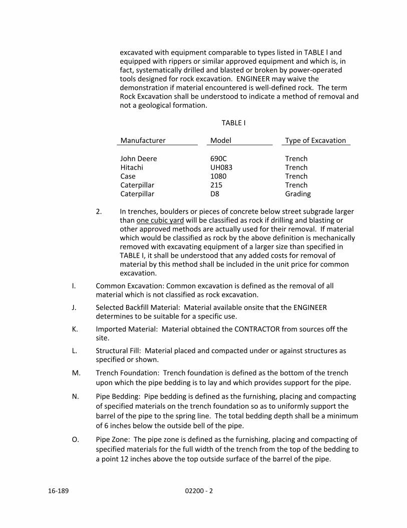
16‐189 02200 ‐ 2
excavated with equipment comparable to types listed in TABLE l and equipped with rippers or similar approved equipment and which is, in fact, systematically drilled and blasted or broken by power‐operated tools designed for rock excavation. ENGINEER may waive the demonstration if material encountered is well‐defined rock. The term Rock Excavation shall be understood to indicate a method of removal and not a geological formation.
TABLE I
Manufacturer Model Type of Excavation John Deere 690C Trench Hitachi UH083 Trench Case 1080 Trench Caterpillar 215 Trench Caterpillar D8 Grading
2. In trenches, boulders or pieces of concrete below street subgrade larger
than one cubic yard will be classified as rock if drilling and blasting or other approved methods are actually used for their removal. If material which would be classified as rock by the above definition is mechanically removed with excavating equipment of a larger size than specified in TABLE I, it shall be understood that any added costs for removal of material by this method shall be included in the unit price for common excavation.
I. Common Excavation: Common excavation is defined as the removal of all material which is not classified as rock excavation.
J. Selected Backfill Material: Material available onsite that the ENGINEER determines to be suitable for a specific use.
K. Imported Material: Material obtained the CONTRACTOR from sources off the site.
L. Structural Fill: Material placed and compacted under or against structures as specified or shown.
M. Trench Foundation: Trench foundation is defined as the bottom of the trench upon which the pipe bedding is to lay and which provides support for the pipe.
N. Pipe Bedding: Pipe bedding is defined as the furnishing, placing and compacting of specified materials on the trench foundation so as to uniformly support the barrel of the pipe to the spring line. The total bedding depth shall be a minimum of 6 inches below the outside bell of the pipe.
O. Pipe Zone: The pipe zone is defined as the furnishing, placing and compacting of specified materials for the full width of the trench from the top of the bedding to a point 12 inches above the top outside surface of the barrel of the pipe.
16‐189 02200 ‐ 3
P. Trench Backfill: Trench backfill is defined as the furnishing, placing, and compacting of material in the trench between the top of the pipe zone material and the bottom of the pavement base rock, ground surface, or surface material.
Q. Base Rock: Base rock is defined as the furnishing, placing, and compacting of material in the trench between the top of the trench backfill and the bottom of the replacement concrete or asphalt surface.
R. Gravel Surface: Gravel surface is defined as furnishing, placing, and compaction of the gravel surface over the backfilled trench, roadway shoulder, or as shown on the plans.
S. Embankment: Embankment is defined as furnishing, placing, and compacting of the embankment material to the depth and configuration shown on the drawings or specified herein.
1.3 Related Work Specified and Performed Under Other Sections Section/Division No. Item
02100 Site Preparation 02520 Base and Leveling Courses for Paving and Surfacing 02530 Asphaltic Concrete Pavement for Paving and Surfacing 02610 Ductile Iron Pipe for Water and Other Liquids 02700 Sanitary Sewerage and Drainage 1.4 CONTRACTOR’s Submittals A. Submittals shall be made in accordance with the requirements of the Standard
General Conditions, Section 01300, and the requirements of this Section.
B. Provide the following submittals:
1. Certifications, test results, source, and samples for all imported material required for “preliminary acceptance.”
2. Copies of permits obtained for excavations, blasting, erosion control, etc. that are required by local, state and federal authorities for the Work.
3. Catalogue and/or manufacturer’s data sheets for compaction equipment.
1.5 Imported Material Acceptance
A. All imported materials specified in this section are subject to the following requirements:
1. All tests necessary for the CONTRACTOR locate an acceptable source of imported material shall be made by the CONTRACTOR. Certification that the material conforms to the specifications requirements along with
16‐189 02200 ‐ 4
copies of the test results from a qualified commercial testing laboratory shall be submitted to the ENGINEER for approval at least 10 days before the material is required for use. All material samples shall be furnished by the CONTRACTOR at the CONTRACTOR’s sole expense. Samples shall be representative and be clearly marked to show the source of the material and the intended use on the project. Sampling of the material source shall be done by the CONTRACTOR in accordance with ASTM D75. Notify the ENGINEER at least 24 hours prior to sampling. The ENGINEER may, at ENGINEER’s option, observe the sampling procedures. Preliminary acceptance of the material source shall be based on an inspection of the source by the ENGINEER and/or the certified test results submitted by the CONTRACTOR to the ENGINEER, at the ENGINEER’s discretion. No imported materials shall be delivered to the site until the proposed source and materials tests have been preliminarily accepted in writing by ENGINEER. Final acceptance will be based on tests made on samples of material taken from the completed and compacted course. The completed course is defined as a course or layer that is ready for the next layer or the next phase of construction. All testing for final acceptance shall be performed by OWNER or OWNER’s authorized representative as specified in Section 01100.
2. Gradation tests by the CONTRACTOR shall be made on samples taken at the place of production prior to shipment. Samples of the finished product for gradation testing shall be taken from prepared materials at frequencies determined by ENGINEER, if variation in gradation is occurring, or if the material appears to depart from the specifications. Test results shall be forwarded to the ENGINEER within 48 hours after sampling.
3. If tests conducted by the CONTRACTOR or the ENGINEER indicate that the material does not meet specification requirements, material placement will be terminated until corrective measures are taken. Material which does not conform to the specification requirements and is placed in the Work shall be removed and replaced at the CONTRACTOR’s sole expense. Sampling and testing performed by the CONTRACTOR shall be done at the CONTRACTOR’s sole expense.
PART 2 PRODUCTS A. Trench Stabilization Material
Imported 3‐inch minus crushed rock or gravel or clean pit run gravel, well graded from course to fine with not more than 8 percent passing the No. 200 sieve.
B. Pipe Bedding & Pipe Zone Backfill
Pipe bedding and pipe zone backfill material shall be imported crushed rock with a maximum size of 1‐inch, free from dirt, clay balls and organic material, with less than 8 percent passing the No. 200 sieve.
C. Select Backfill Material

16‐189 02200 ‐ 5
Select backfill material shall be native excavated material which shall have more than 90 percent passing the 3‐inch sieve and more than 50 percent passing the 1‐inch sieve and not more than 20 percent passing the No. 200 sieve. Select backfill shall be clear of weeds, refuse, sticks, or other organic material larger than 1‐inch which in the ENGINEER's opinion would compromise the integrity of the compacted trench. Material excavated for structures and utilities may be used for select backfill material at ENGINEER’s discretion.
D. Trench Backfill
Trench backfill shall consist of imported crushed gravel or rock meeting the requirements of pipe bedding and pipe zone backfill specified above.
E. Subgrade Stabilization Material
Subgrade stabilization material shall be imported crushed rock with a maximum size of 3‐inches, free from dirt, clay balls and organic material, with less than 8 percent passing the No. 200 sieve.
F. Structural Fill
Imported 4‐inch minus crushed rock free from dirt, clay balls and organic material, conforming to the testing requirements of the Standard Specification Section 00330.16, Stone Embankment Material.
G. Base Rock
Base rock shall be imported crushed rock as specified under trench backfill.
H. Gravel Surface
Gravel surface shall be imported crushed rock as specified under trench backfill.
I. Pit Run
Pit run or bar run material well graded from coarse to fine. The maximum dimension shall be 3 inches.
J. Drain Rock
Drain rock shall consist of washed, round rock, graded from 1‐1/2 inches to 3/4 inches.
K. Embankment
Embankment materials shall be as shown on the drawings and shall consist of select backfill material compacted to the specified optimum density.
L. Topsoil
Topsoil shall be imported, friable, fertile, natural surface loam consisting of sands, silts, clays and organic matter in combination and free of noxious weeds, roots, refuse, sticks, lumps, and substances toxic to plant growth.
M. Controlled Density Backfill (referred to as CDF)

16‐189 02200 ‐ 6
Controlled density backfill material shall be composed of Portland cement, aggregate, fly ash, and water and shall conform to the following requirements:
1. Portland Cement: ASTM C 150, Type I or II 2. Aggregate meeting the following gradations:
Sieve % Passing 3/8" 100 1/4" 60 ‐ 100 #200 5
3. Water (Potable). 4. Fly Ash: Class F, ASTM 618, unless otherwise approved. 5. Admixture: As necessary to improve flowability without segregation.
6. Unconfined compressive strength at 28 days shall be 100 psi per ASTM D4832. Maximum density 100 pcf.
7. CONTRACTOR may need to modify the above mix design for trenches constructed on steep slopes to prevent the material from flowing down the trench slope. Submit modified mix design to ENGINEER for review.
PART 3 EXECUTION 3.1 Clearing, Grubbing and Stripping
A. Complete clearing, grubbing, and stripping work as specified in Section 02100, SITE PREPARATION prior to beginning work in this Section.
3.2 General Excavation
A. Excavation is classified; see Article 1.2 Definitions for classifications. Notify ENGINEER whenever rock is encountered.
B. Before beginning rock excavation, comply with the following requirements:
1. Remove overlying material as Common Excavation and expose rock for examination by ENGINEER.
2. Demonstrate that removal of remaining material classifies as rock excavation unless waived by ENGINEER.
3. Assist ENGINEER with measurement and documentation of rock excavation.
C. Limits of Excavation: Excavate to the depths and widths specified or shown, allowing for forms, shoring, working space, base material and finished topsoil where required. Do not excavate deeper than shown on the plans. Excavation carried below grades shown without approval shall be replaced with compacted foundation stabilization material at the CONTRACTOR's expense.
16‐189 02200 ‐ 7
D. Disposal of Excess Material: Excavated material approved for use as select native backfill or embankment shall be placed at locations and in such a manner that it does not obstruct or create a hazard to pedestrian or vehicular traffic, or interfere with the function of existing drainage facilities or fall outside construction easements or public right‐of‐way. All streets and roadways shall be kept open to two way traffic unless approved by the OWNER. When private property is used as a stockpile location, prior to placement of stockpile material, CONTRACTOR shall provide the OWNER with written approval from the property owner. Excavated materials not suitable or not required for backfill or embankment as directed by ENGINEER, shall be deposited on one or both of the following sites:
1. Disposal on Pre‐designated Sites. When sites for excess material are contained on the plans, disposal operations shall be performed as ENGINEER may direct. OWNER will secure all necessary disposal permits for the required work completed under this item.
2. Sites Provided by CONTRACTOR. All excess material not required for disposal at pre‐designated sites shall be disposed of by the CONTRACTOR. When disposing within the City of Lake Oswego, CONTRACTOR must obtain a fill permit from the City of Lake Oswego Building Department.
E. Existing Abandoned Facilities: CONTRACTOR shall remove and dispose of
existing abandoned sewer pipe, structures, and other facilities as necessary to prosecute the Work in accordance with these Contract Documents. Unless the bid schedule includes an item for removal of existing abandoned facilities, the cost of such removal will be considered incidental to excavation and backfill.
F. Dewatering: CONTRACTOR shall promptly remove and dispose of all water, including flow from existing storm drain lines, surface and subsurface flow entering the trench during the time the trench is being prepared for the pipe laying, during the laying of the pipe and until the backfill at the pipe zone has been completed. CONTRACTOR shall dispose of the water in a suitable manner without damage to public or private property, or nuisance or menace to the public.
G. Shoring: Whenever necessary to prevent caving during excavation the trench shall be adequately sheeted and braced. Where sheeting and bracing are used, trench widths shall be increased accordingly. Installation and maintenance of sheeting, shoring and bracing shall comply with Oregon OSHA and other applicable Federal, State or local requirements having jurisdiction.

16‐189 02200 ‐ 8
3.3 Trench Excavation
A. Open Trench Limit: The length of open trench shall be kept to a minimum. ENGINEER shall be the sole judge of the amount of trench allowed open based upon work conditions of the area. In normal cases, the open trench length shall not exceed 250 feet. Related construction such as pavement, road gravel, concrete restoration, etc., shall be completed within 800 feet of the open trench limit. All trenches shall be maintained as specified under trench maintenance.
B. Trench Width: Trench width at the ground surface shall be kept to the minimum necessary to install the pipe in a safe manner but not less than eighteen (18) inches greater than the outside diameter of the bell of the pipe except as otherwise allowed by the ENGINEER. In all cases, trenches must be of sufficient width to allow for shoring and permit proper joining of the pipe and backfilling of material along the sides of the pipe. The minimum trench width in the pipe zone shall provide a clear working space of 9 inches between the outside surface of the pipe bell and the sides of the excavation. Maximum trench width shall be limited to l.5 times the nominal pipe diameter plus eighteen (18) inches. Excavation for manholes and other structures shall be wide enough to provide a minimum of 12 inches between the structure surface and the sides of the excavation. The top of the trench shall be confined to rights of way or easements.
C. Trench Grade: CONTRACTOR shall excavate the trench to the lines and grades shown or specified, with proper allowance for pipe thickness, pipe bedding and foundation stabilization. The foundation upon which the bedding is to be placed shall be firm, undisturbed, and true to grade.
D. Trench Maintenance: Unless specified otherwise, all excavations within hard surfaces shall be paved with a temporary cold mix asphalt patch at the end of each work day. All backfilled trenches in the roadway shall be maintained in such manner that no chuck‐holes, ruts or drop‐offs exist during the course of construction.
E. Trench Protection: Trenches and open excavations shall not be left open overnight. Excavations within the right‐of‐way shall be completely backfilled or shored and covered with metal trench plates before CONTRACTOR leaves the site each day. Excavations on private property shall be covered and protected. Metal trench plates located within traffic areas shall be secured by means of pins or asphalt berms or as approved by ENGINEER to reduce the amount of plate movement and noise resulting from vehicular traffic.
3.4 Trench Backfill
A. Trench Foundation: When, in the opinion of the ENGINEER, the existing material in the bottom of the trench is unsuitable for supporting the pipe, CONTRACTOR

16‐189 02200 ‐ 9
shall over excavate such unsuitable material as directed by ENGINEER. The excavated material shall be disposed of and replaced with trench stabilization material as specified herein.
B. Pipe Bedding: CONTRACTOR shall spread the bedding smoothly to the proper depth and grade so that the pipe is uniformly supported along the barrel and shall excavate bell holes at each joint to permit proper assembly and inspection of the joint. Bedding under the pipe shall provide a firm, unyielding support along the entire pipe length. CONTRACTOR shall place subsequent lifts of not more than 6 inches in thickness up to the spring line of the pipe, bringing lifts up equally on both sides of the pipe.
C. Pipe Zone: Pipe zone material shall be carefully placed around the pipe and thoroughly compacted in 6‐inch layers to provide complete support of the pipe and to prevent deflection or damage. The material under the pipe haunches shall be thoroughly "sliced‐in" with a shovel and compacted. CONTRACTOR shall prevent pipe from movement either horizontally or vertically during placement and compaction of pipe zone material.
D. Trench Backfill: When select backfill is used for backfill, CONTRACTOR shall take reasonable precautions to prevent excavated material from becoming saturated beyond the optimum moisture limits and replace any saturated native material with imported select backfill material, as approved by ENGINEER, at no additional expense to OWNER. CONTRACTOR shall backfill the trench above the pipe zone in successive lifts not exceeding 18‐inches in depth. Backfill shall not be allowed to free‐fall into the trench until at least 3 feet of cover is provided over the top of the pipe. The method of compaction shall be modified as necessary to protect the pipe.
Install trench backfill as specified below. Unless otherwise shown or specified, all compaction is to meet 95% ASTM D1557. 1. Class 1 & 2 Backfill. The trench above the pipe zone shall be backfilled in
twenty‐four inch layers and compacted. The fill shall be brought to the required surface grade, and compaction shall be such that no settlement will occur.
2. Class 3 Backfill. Following backfill in the pipe zone, backfill may be pushed back into the trench by mechanical means. Where this method of backfill is allowed, the earth shall be pushed first onto the slope of the backfill previously placed and allowed to roll down into the trench. CONTRACTOR will not be allowed to push the backfill material into the trench in such a way as to permit free fall of the material into the open trench. After the backfill has been completed, the entire working area including the trench shall be compacted and unless otherwise stated in the contract special specifications, graded consistently with the surrounding surfaces.

16‐189 02200 ‐ 10
3. Class 4 Backfill. The trench above the pipe zone shall be backfilled in lifts not exceeding twenty‐four inches in depth. The entire trench shall be compacted. All trenches in the street shall be Class 4 Backfilled, or CDF as approved by Engineer.
4. Controlled Density Backfill (CDF). The trench above the pipe bedding shall be backfilled with controlled density backfill. The CDF shall be mixed to ensure a uniform distribution of materials throughout the mass and placed to avoid segregation and remain free of voids. CDF shall be placed within 90 minutes after batching. Prior to placing CDF around new valves, CONTRACTOR shall place valve box and riser over valve bonnet and then wrap valve bonnet and riser with 6 mil. plastic. Support riser and valve box to ensure plumbness. Provide metal hoops, hooks or other ENGINEER approved methods to prevent flotation of PVC pipe when CDF backfill is used.
3.5 Structural Embankments
A. Prior to construction of embankments, excavate and dispose of unstable material or unsuitable foundation material. Limit excavation to lines and grades and cross sections shown. Backfill voids which fall within embankment limits with specified material. If the surface of the prepared foundation or compacted surface of a preceding lift is too dry or smooth to bond properly with the next layer of material, moisten or scarify, or both before the next layer of material is placed. CONTRACTOR shall construct embankment to support the pipeline in accordance with the details shown on the plans. CONTRACTOR shall spread excess excavated trench material suitable for embankment, or approved imported material when directed, in maximum 1‐foot lifts for the full width of the embankment cross section and compact to a minimum of 95 percent of maximum density for the full depth of the fill as determined by ASTM D1557. CONTRACTOR shall moisten or dry layers of fill as required to obtain the compaction specified and compact the embankment to final cross section before the trench excavation for the pipe is made. In locations where insufficient pipe cover exists, place native material suitable for embankment over the pipe to provide a minimum pipe cover of three (3) feet. Compact as required for underlying trench backfill.
3.6 Structural Fill:
A. Place structural fill under piping, slabs, walks, curbs, structures, facilities, and other areas as shown, specified or directed by ENGINEER. Do not exceed loose lifts of 12 inches. Compact each lift to not less than 95 percent of relative compaction. Stop structural fill 9 inches below finished grade in areas to receive topsoil. Moisten material as required to aid compaction. Place material in horizontal lifts and in a manner which avoids segregation. Any subsequent

16‐189 02200 ‐ 11
damage to slabs, piping, concrete structures, facilities, or other structures caused by settlement of fill material shall be corrected and repaired by the CONTRACTOR at the CONTRACTOR’s sole expense.
3.7 Compaction A. Compaction Testing: Prior to commencing field testing, CONTRACTOR shall
notify the City's inspector. At the end of each test period a completed copy of the test results shall be provided to the City. The City reserves the right to require additional tests at no additional cost to the City.
If the compaction specified for trench backfill or embankment is not obtained, CONTRACTOR will immediately stop the material placement and compaction operation and modify the compaction procedure to a method which satisfies the required specification. In no case shall embankment or trench backfill operations proceed until CONTRACTOR is able to compact the backfill material to the satisfaction of the ENGINEER.
END OF SECTION

16‐189 02240 ‐ 1
DIVISION 2 SITE WORK
SECTION 02240 GEOTEXTILES PART 1 GENERAL 1.1 Scope
This Section specifies work necessary for providing geotextiles in drains, under embankments, for embankment reinforcement, under riprap, buttresses, inlays, shear keys and erosion control applications, behind retaining structures, over roadbed subgrades, and beneath pavement overlays, as shown on the drawings or specified in these contract documents.
1.2 Definitions A. Geotextile: A fabric manufacturer specifically for use in civil engineering
applications. Fibers used in the manufacture of geotextiles consist of long chain synthetic polymers. At least 85 percent by weight of the long chain polymers are polyolephins, polyesters, or polyamides.
B. Drainage Geotextile: For installation in subsurface drains or other drainage locations.
C. Embankment Geotextile: For installation within or under embankments for stabilization.
D. RipRap Geotextile: For installation behind and beneath riprap, buttresses, inlays, shear keys, and erosion control applications.
E. Subgrade Geotextile: For installation on subgrades and in other material separation applications.
F. Pavement Overlay Geotextile: For installation beneath an asphalt concrete overlay.
1.3 Related Work Specified and Performed Under Other Sections Section/Division No. Item
02100 Site Preparation 02200 Earthwork 02520 Base and Leveling Courses for Paving and Surfacing 02530 Asphaltic Concrete Pavement for Paving and Surfacing 02710 Subdrainage Systems 03300 Concrete

16‐189 02240 ‐ 2
1.4 CONTRACTOR’s Submittals A. Submittals shall be made in accordance with the requirements of the Standard
General Conditions, Section 01300, and the requirements of this Section.
B. Provide the following submittals:
1. Certifications, test results, source, and samples for all material required for “preliminary acceptance.”
2. Catalogue and/or manufacturer’s data sheets for geotextiles proposed to be furnished under this Section.
PART 2 PRODUCTS 2.1 General
A. Geotextiles shall:
1. Be composed of a polymeric yarn or fiber oriented into a stable network, which retains its relative structure during handling, placement, and design service life.
2. Meet or exceed the minimum properties of Section 02320 of the Standard Specification or as specified herein.
3. Be free from defects or tears.
4. Be resistant to ambient temperatures, acid and alkaline conditions, microorganisms and insects.
5. Be for the intended purpose and have dimensional stability.
B. Approved Manufacturers, or equal.
1. Mirafi, Inc., P.O. Box 240967, Charlotte, NC 28224.
2. Amoco Fabrics and Fibers CO., Atlanta, GA 30339.
PART 3 EXECUTION 3.1 General
A. Provide full rolls of geotextile as furnished from the manufacturer. Protect against damage and deterioration by storing rolls in a dry place and above ground at all times until placement. Cover rolls and partial rolls until used with a dark protective covering. Geotextiles will be rejected by ENGINEER if found to be defective, deteriorated or damaged.
3.2 Installation
A. Install geotextiles in accordance with manufacturer’s recommendation or Section 00350 of ODOT Standard Specification unless specified otherwise herein.
END OF SECTION

16‐189 02241 ‐ 1
DIVISION 2 SITE WORK
SECTION 02241 COMPOSITE GRID PAVING INTERLAYER
PART 1 GENERAL
1.01 Description
This section includes specifications for placing the composite paving grid at the locations
and to the dimensions shown on the plans and as directed by the ENGINEER.
PART 2 PRODUCT
2.01 Materials
A. The composite grid paving interlayer shall be constructed of uncoated multi‐
directional continuous strand high strength fiberglass fibers, mechanically bound
to a polypropylene fabric, to provide multi‐directional tensile conforming to the
following test methods and physical properties as shown in Table 2.01A –
Composite Paving Grid Nominal Properties.
Table 2.01 A – Composite Paving Grid Nominal Properties
Property
ASTM Test
Method Units Type I
Tensile Strength @ 0°
D6637 lbs/in (kN/m) 286 (50)
Tensile Strength @ 90° 1Tensile Strength @ 45° 1Tensile Strength @ ‐45°
Elongation at Max Load % < 4.0
Melting Point (glass) D276 °F (°C) 752° (400°)
Asphalt Retention D6140 gal/yd2
(liters/m2) .17 (0.8)
Mass per Unit Area D5261 oz/yd2 (g/m2) 14 (475) 1Modified to test at 45° angle to confirm multi‐directional tensile
B. The composite paving grid shall be PGM G4 or MPG4 as manufactured and
distributed by TenCate Mirafi or approved equal.

16‐189 02241 ‐ 2
2.02 Storage
A. The composite paving grid roll shall be wrapped in protective wrapping. A
durable label shall be on the outside of the wrapping indicating manufacturer,
product name or style number, roll and lot number, and roll dimensions.
B. The composite paving grid rolls shall be delivered, stored and handled in a
manner to prevent damage. The composite paving grid rolls shall be inspected
for defects and damage after unloading.
C. The composite paving grid shall be stored per manufacturer’s recommendation –
in a dry covered condition free from dust, dirt, and moisture. The composite
paving grid rolls shall be stored off the ground, protected from precipitation,
ultraviolet radiation, strong chemicals, sparks and flames, temperatures in
excess 71°C (160°F) and other environmental condition that could cause
damage.
PART 3 – EXECUTION
3.01 Surface Preparation
A. All areas of base failure shall be removed and replaced to acceptable industry
standards for the specific traffic loads and condition of the project.
B. In an overlay or milled surface application repair all failed pavement areas prior
to installation of the composite paving grid. Fill all cracks ¼” or greater with
approved material.
C. Immediately prior to placement of composite paving grid, the pavement shall be
dry, cleaned of loose and extraneous materials such as, but not limited to,
vegetation, sand, dirt, gravel, and water.
D. When finish grinding is used as an alternative to an asphalt leveling course being
placed over conventional grinding prior to the placement of an interlayer
product, the final surface texture shall have gaps no greater than ¼” depth and
width or be acceptable to the ENGINEER.
3.02 Installation
A. Over a new asphalt section or where a leveling course has been installed, apply
the composite paving grid in a hot PG graded asphalt binder. Asphalt Emulsion is NOT
acceptable for placing composite paving grid.

16‐189 02241 ‐ 3
B. Asphalt Binder
1. A hot asphalt binder shall be applied to saturate the composite paving
grid and bond to existing surface and the new overlay. The asphalt
binder to be used shall be PG64‐22 or higher.
2. The hot asphalt binder shall be applied at a rate of 0.18 to 0.20 gal/SY on
a new asphalt concrete leveling surface. On an old smooth surface or a
clean fine milled surface apply hot asphalt binder at a rate of 0.20 to 0.22
gal/SY or as recommended by the composite paving grid manufacturer or
as directed by the ENGINEER.
3. The hot asphalt binder shall be applied by a distributor truck in a smooth
uniform manner at a temperature between 177°C (350°F) and 204°C
(400°F). Spray application shall be four (4) inches wider than width of
composite paving grid on lap side.
C. The composite paving grid shall be installed with equipment in good working
order that is capable of installing the grid without wrinkles or manually as
needed and recommended by manufacturer.
1. If manual lay‐down methods are used, the composite paving grid shall be
unrolled, aligned, and placed in increments of approximately thirty (30)
feet as recommended by the composite paving grid manufacturer.
2. The material shall be placed flat and wrinkle‐free. The paving grid
installation may require hand brooming as necessary to eliminate ripples
that may occur during installation.
3. To ease installations around curves, the paving grid can be placed in
shortened lengths by mechanical equipment or by hand.
4. Composite paving grid shall be lapped two (2) to four (4) inches
longitudinally and two (2) to four (4) inches transversely. Transverse laps
shall be in the direction of the asphalt concrete overlay placement
insuring hot asphalt binder is placed under the overlap.
5. Brooming of paving grid is required to insure adequate adhesion into the
hot asphalt binder. If the composite paving grid wrinkles during
installation and the height of the wrinkle is 1 inch or more, the wrinkle
shall be cut and lapped in the direction of paving.
6. Composite paving grid may be installed by unrolling in a clockwise or
counterclockwise direction.

16‐189 02241 ‐ 4
7. Turning of construction equipment and other vehicles shall be gradual
and kept to a minimum to avoid damage to the composite paving grid. If
excessive heat, overspray, or turning cannot be eliminated then
spreading small quantities of asphalt concrete or clean blotting sand may
be required onto the composite paving grid in the affected area. Excess
blotting sand shall be removed before installing asphalt concrete over the
composite paving grid.
8. After installing the paving grid, the roadway may not be opened to traffic.
9. Wet paving grid should never be installed nor should composite paving
grid be installed onto a wet pavement.
3.03 Workmanship and Quality Control
A. Composite Paving Grid Installation Quality Control
1. Quality Control Person: A manufacturer’s trained quality control person
shall be present, at minimum, for the first two days of paving grid
installation and be available thereafter upon request by the engineer.
2. Binder Certification: A certification of compliance from the binder
supplier, shall be provided for each load of hot asphalt binder delivered
to the jobsite, showing the type and quality of material delivered.
END OF SECTION

16‐189 02520 ‐ 1
DIVISION 2 SITE WORK
SECTION 02520 BASE AND LEVELING COURSES FOR PAVING AND SURFACING PART 1 GENERAL 1.1 Scope
This Section specifies furnishing all materials, labor and equipment for the construction of the aggregate base and leveling course, complete as shown on the Drawings and specified herein.
PART 2 PRODUCTS 2.1 Base Course Materials
Material for the aggregate base course shall be imported crushed rock or crushed gravel as the CONTRACTOR may elect, with a maximum size of 1 1/2 inches, free from dirt, clay balls and organic material. When the crushed gravel is used, that portion of the materials therein which is retained on a l/4 inch sieve, shall contain 45% minimum by weight of particles which shall have at least one fractured face produced by mechanical crushing. This fracture requirement shall be applicable uniformly throughout the grading of the materials involved. The material shall be subject to testing for conformance thereto on each of the gradations to which the materials are divided in determining conformance to the requirement for grading of materials.
2.2 Leveling Course Material Material for the leveling course shall be crushed rock or crushed gravel as the CONTRACTOR may elect, with a maximum size of 1‐inch. All requirements shall be as specified in Paragraph 2.1 above, except the percentage by weight of particles having at least one fractured face retained on a 1/4 inch sieve shall be 90 percent.
2.3 Subgrade Stabilization Material As specified in Section 02200, Earthwork.

16‐189 02520 ‐ 2
PART 3 EXECUTION 3.1 Placing Base Course
Place aggregate base course on the prepared subgrade to such a depth that when thoroughly compacted, it will conform to the lines and grades shown on the Drawings with proper allowance for the leveling course hereinafter specified. The base course shall be built up in layers, none of which shall exceed six inches in compacted thickness. Aggregate base rock shall be spread in an even course of uniform thickness from vehicles equipped with spreading devices. Segregation of material shall be avoided and the material as spread shall be free from pockets of large or fine material. In general, the spreading shall begin at the end of the work furthest from the point of loading materials. The dumping of base course materials in piles upon the subgrade will not be permitted.
3.2 Compaction After the base course has been spread and brought to line and cross sections, it shall be compacted with approved equipment to achieve 95% relative density per ASTM D1557. Sufficient water shall be added as needed to facilitate the movement of key material into the voids.
3.3 Surface Finish The surface of the base course shall parallel the cross section and grade established for the top of base course within 0.06 foot.
3.4 Placing Leveling Course Place aggregate leveling course on the completed base course to such a depth that when thoroughly compacted, it will conform to the lines and grades shown on the Drawings with proper allowance for the finished pavement. The leveling course shall be bladed and rolled to a true surface and cross section. The finished surface of the leveling course shall not vary more than 0.04 foot above or below the specified cross section or grade at any point. Compaction of the leveling course shall be performed as hereinbefore specified for aggregate base course.
END OF SECTION

16‐189 02530 ‐ 1
DIVISION 2 SITE WORK
SECTION 02530 ASPHALT CONCRETE (AC) PAVEMENT PART 1 GENERAL 1.1 Scope
This section consists of constructing asphalt concrete (AC) pavement to the lines, grades, thicknesses, and cross sections shown or established.
1.2 Abbreviations
A. HMAC – Hot Mixed Asphalt Concrete
B. WMAC – Warm Mixed Asphalt Concrete C. AC – Asphalt Concrete, may be either HMAC or WMAC
D. TSR ‐ Tensile Strength Ratio
E. VFA ‐ Voids Filled with Asphalt
F. VMA ‐ Voids in Mineral Aggregate G. MFTP – Manual of Field Test Procedures
1.3 Definitions A. Hot Mixed Asphalt Concrete (HMAC)
A hot plant mixed, uniformly coated mixture of asphalt cement, graded aggregate and additives as required.
B. Warm Mix Asphalt Concrete (WMAC) An asphalt concrete mix following all the requirements of HMAC except that through the use of additives or processes it is mixed and placed at lower temperatures. The term WMAC shall be used interchangeably with HMAC except in Section 3.5. The Contractor may use warm mix asphalt concrete (WMAC) as a substitute for HMAC on

16‐189 02530 ‐ 2
all paving. WMAC will be subject to all requirements for HMAC, except as modified in these provisions.
C. Level 1 AC
AC for use in applications with very low traffic and only limited exposure to trucks.
D. Level 2 AC
AC for use in applications with low traffic volumes and low volume truck traffic. E. Level 3 AC
AC for use in applications exposed to moderate truck traffic.
F. Reclaimed Asphalt Pavement (RAP) Material
Reclaimed AC pavement (RAP) material used in the production of new AC is optional. No more than 30% RAP material will be allowed in the new AC pavement.
PART 2 PRODUCTS
Testing of aggregates for soundness, durability, and harmful substances will be at the discretion and expense of the City.
2.1 Aggregate
Furnish coarse, fine, and RAP aggregates for AC meeting the following requirements:
A. Soundness Provide coarse and fine aggregate with a weighted loss not exceeding 12% when subjected to five cycles of the soundness test using sodium sulfate solution according to AASHTO T 104.

16‐189 02530 ‐ 3
B. Durability Provide aggregate not exceeding the following maximum values: Test Method Aggregates Test ODOT AASHTO Coarse
Abrasion T 96 30.00% Degradation Passing No. 20
sieve TM 208 30.00% Sediment Height TM 208 3.0"
C. Fractured Faces
Provide crushed aggregate with not less than the minimum number of fractured faces as determined by AASHTO TP 61 as follows:
Percent of Fracture (by Weight)
Material Retained on 1 1/2", 1", 3/4", 1/2" Material Retained and No. 4 Sieve on No. 8 sieve
Type of Mix (two fractured faces) (one fractured face)
All Dense Graded AC 75 75
D. Harmful Substances Do not exceed the following maximum values:
Test Method Aggregates Test ODOT AASHTO Coarse Fine
Lightweight pieces T 113 1.00% Wood Particles TM 225 0.10% Elongated Pieces (at a ratio of 5:1) TM 229 10.00% Plasticity Index T 90 0 or NP Sand Equivalent T 176 45 min

16‐189 02530 ‐ 4
E. Coarse Aggregate Produce coarse aggregate from crushed rock or other inert material of similar characteristics.
F. Fine Aggregate Produce fine aggregate from crushed rock or other inert material of similar characteristics. Blend sand is allowed. Do not blend more than 10% by weight of natural or uncrushed blend sand into the total fine aggregate unless approved. Provide a means of verifying and documenting the amount of blend sand added to the aggregate.
G. RAP Aggregate Use RAP aggregates in the AC, according to Section 1.3.F, that are no larger than the specified maximum allowable aggregate size before entering the cold feed. Blend the RAP material with new aggregate to provide a mixture conforming to the JMF within the tolerances specified.
2.2 Asphalt Cement and Additives
Furnish the following: A. Asphalt Cement
Use PG 64‐22 or PG 70‐22 asphalt unless otherwise specified in the Contract documents. Provide asphalt cement conforming to the requirement of ODOT’s publication "Standard Specifications for Asphalt Materials". Copies of the publication are available from ODOT’s Pavement Services Engineer (www.oregon.gov/odot). The applicable specifications are those contained in the current publication on the date the Project is advertised. Testing of the asphalt cement used on this Project will be at the discretion and expense of the City.
Asphalt in RAP material, when blended with new asphalt shall provide properties similar to the above specified asphalt. When RAP material is used at a rate of less than 15%, no adjustment to the new asphalt will be required. When utilizing RAP at a rate at or above 15%, the combined RAP and new asphalt shall provide blended properties equivalent to the specified grade. Determine the blended properties

16‐189 02530 ‐ 5
according to ASTM D 4887. Determine asphalt cement properties for the RAP material from asphalt cement recovered from the RAP according to AASHTO T 170.
B. Asphalt Cement Additives
When required by the JMF, add antistripping additives meeting the requirements below and satisfying the Tensile Strength Ratio (TSR) specified in Section 2.4. Additives to prevent stripping or separation of asphalt coatings from aggregates, and admixtures used to aid in the mixing or use of asphalt mixes or for experimental purposes, shall be standard recognized products of known value for the intended purpose and approved for use on the basis of laboratory tests. They shall have no deleterious effect on the asphalt material and be completely miscible. Do not use silicones as an additive.
C. For WMAC The additives or processes listed on the following table, or approved equal, shall be used on this contract.
WMAC Technology Process Type Supplier
Advera (Synthetic Zeolite) Foaming process PQ Corporation
Aspha‐min (Synthethic Zeolite) Foaming process Aspha‐Min
Evotherm Chemical additive Mead/Westvaco Asphalt Innovations
Redi‐Set WMX Chemical additive Akzo Nobel Surfactants, Inc
Sasobit Organic additive Sasol Wax Americas, Inc.
Plant Foaming Equipment Foaming process Various Suppliers
2.3 Mix Type and Broadband Limits
Mix type and broadband limits shall meet the following:
A. Mix Type Furnish the type(s) of AC shown or as directed. The broadband limits for each of the mix types are specified in (B) below. When the plans allow an option of two types for a course of pavement, use only one type throughout the course.

16‐189 02530 ‐ 6
B. Broadband Limits Provide a JMF for the specified mix type within the control points listed below:
Sieve Size 3/4" Dense 1/2" Dense 3/8" Dense
Control Points Control Points Control Points
(% passing by Weight)
(% passing by Weight)
(% passing by Weight)
Min. Max. Min. Max. Min. Max.
1" 100 3/4" 90 100 100 1/2" ‐ 90 90 100 100 3/8" ‐ ‐ ‐ 90 90 100 No. 4 ‐ ‐ ‐ ‐ ‐ 90 No. 8 23 49 28 58 32 67
No. 200 2.0 8.0 2.0 10.0 2.0 10.0
2.4 Job Mix Formula (JMF) Requirements
Provide a JMF for the Project meeting the following criteria and that was either developed or verified within three years of the date the Contract was advertised:
Level 1 Level 2 Level 3
Design Method Superpave Superpave Superpave Compaction Level 65 Gyrations 65 Gyrations 80 Gyrations Air Voids, % 3.5 4.0 4.0 VMA, % minimum 1/2 inch ‐ 14.0 3/4 inch ‐ 13.0 3/4 inch ‐ 13.0
3/8 inch ‐ 15.0 1/2 inch ‐ 14.0 1/2 inch ‐ 14.0 3/8 inch ‐ 15.0 3/8 inch ‐ 15.0
VMA, % maximum min + 2.0% min + 2.0% min + 2.0% P No. 200 / Eff. AC ratio 0.8 to 1.6 0.8 to 1.6 0.8 to 1.6 TSR, % minimum 80 80 80 VFA, % 70 ‐ 80 65 ‐ 78 65 ‐ 78
3/8 inch: 70 ‐ 80
3/8 inch: 70 ‐ 80 3/8 inch: 70 ‐ 80
The JMF shall have been developed according to the ODOT Contractor Mix Design Guidelines for Asphalt Concrete or verified according to the ODOT Mix Design

16‐189 02530 ‐ 7
Verification process. Submit the proposed JMF and supporting data to the Engineer for review at least 10 calendar days before anticipated use. If acceptable, written acceptance will be provided. Perform a new TSR if the source of the asphalt cement changes.
2.5 Tolerances and Limits
Produce and place AC within the following JMF tolerances and limits:
Gradation AC Type Constituent 3/4" 1/2" 3/8"
1" JMF ± 5%* 3/4" 90 ‐ 100% JMF ± 5%* 1/2" JMF ± 5% 90 ‐ 100% JMF ± 5%* 3/8" ‐ ‐ 90 ‐ 100% No. 4 JMF ± 5% JMF ± 5% JMF ± 5% No. 8 JMF ± 4% JMF ± 4% JMF ± 4% No. 30 JMF ± 4% JMF ± 4% JMF ± 4% No. 200 JMF ± 2.0% JMF ± 2.0% JMF ± 2.0%
* Maximum not to exceed 100%
Constituent of Mixture AC All Types Asphalt Cement ‐ ODOT TM 321 (Cold Feed/Meter) JMF ± 0.20% Asphalt Cement ‐ AASHTO T 308 (Ignition) and ODOT TM 323 JMF ± 0.50% RAP Content ‐ ODOT TM 321 JMF ± 2.0% Moisture content at time of discharge from the mixing plant ‐ WAQTC TM 6 0.80% max. When a JMF tolerance applies to a constituent, full tolerance will be given even if it exceeds the Control Points established in Section 2.3.B.
2.6 AC Acceptance
The mixture will be accepted by visual inspection by the Engineer. If the mixture is considered suspect, the Engineer may verify that the mixture is within tolerances and limits of Section 2.4. When requested, obtain samples according to appropriate

16‐189 02530 ‐ 8
procedures in the MFTP under the observation of the Engineer at a frequency established by the Engineer. The Engineer will test for gradation, asphalt content, moisture, and RAP content (if applicable) according to procedures specified in Section 2.4 and the MFTP. Take corrective action when testing shows that AC is not within the tolerances and limits of Section 2.4.
PART 3 EXECUTION 3.1 Equipment
Compactors Provide self propelled rollers capable of reversing without backlash as follows: A. Steel‐Wheeled Rollers
Steel‐wheeled rollers shall have: • A gross static weight of at least 8 ton.
If steel‐wheeled rollers are used for finish rolling, they shall have: • A gross static weight of at least 6 ton.
B. Vibratory Rollers
Vibratory rollers shall be: • Equipped with amplitude and frequency controls.
• Specifically designed to compact AC. • Capable of at least 2,000 vibrations per minute. • Have a gross static weight of at least 8 ton.
Do not operate in vibratory mode for lifts thinner than two times the maximum aggregate size for the type of AC being compacted.
3.2 Construction
Season and Temperature Limitations Place AC when the temperature of the surface that is to be paved is not less than the temperature indicated, unless otherwise approved by the ENGINEER:

16‐189 02530 ‐ 9
Nominal Compacted All Levels Level 1 and Level 2 Level 3 Thickness of Individual Lifts and Courses as Travel Lane All Other shown on the typical All Courses Wearing Course Courses section of the plans
Surface From To From To From To Temperature* Inclusive Inclusive Inclusive
Dense Graded Mixes Less than 2 inches 60 °F All Year** 3/15 9/30 All Year** 2 inches ‐ 2 1/2 inches 50 °F All Year** 3/15 9/30 All Year** Greater than 2 1/2 inches 40° F All Year** 3/15 9/30 All Year** Temporary 40 °F All Year** All Year** All Year**
* If placing AC between March 15 and September 30, temperature requirement may be lowered 5 °F or as approved by the ENGINEER. ** Do not use field burners or other devices to heat the pavement surface to the specified minimum temperature.
3.3 AC Mixing Temperatures
Produce AC within the temperature ranges recommended by the asphalt cement supplier for the grade of asphalt being used on the Project.
3.4 Tack Coat
A. This work consists of furnishing and placing emulsified asphalt on a prepared asphalt concrete, Portland cement concrete, or other paved surface to ensure bond between lifts as specified.
B. Materials
1. Emulsified Asphalt
Furnish CSS‐1, CSS‐1h, CMS‐2, CMS‐2S, CMS‐2h, CRS‐1, CRS‐2, HFRS‐2, or HFMS 2 as selected by the Contractor.
Furnish emulsified asphalt meeting the requirements of ODOT's publication "Standard Specifications for Asphalt Materials". Copies of the publication are available from the ODOT Pavement Services Engineer (www.oregon.gov/odot). The applicable specifications are those contained in the current publication on the date the Project is advertised. Limit pumping between the bulk storage tank, hauling transportation, field storage

16‐189 02530 ‐ 10
tanks and distributor to an absolute minimum to maintain proper viscosity. Acceptance of emulsified asphalt will be at the point of application.
Dilution of the tack coat material may be allowed to a maximum 1:1 ratio. Determine the proportion of water to be added to the emulsified asphalt. Do not dilute the emulsified asphalt until the Engineer approves the dilution ratio. Add the water to the emulsified asphalt and mix according to the asphalt supplier. Obtain samples according to AASHTO T 40 prior to dilution with water, if allowed, at the frequency indicated in the MFTP. Samples will be tested at the ODOT Materials Laboratory, or other laboratory as designated by the City. Emulsified asphalt will be tested within 30 calendar days from the date it is sampled.
C. Equipment
1. Asphalt Distributor
Provide an asphalt distributor designed, equipped, maintained and operated so the emulsified asphalt material may be applied uniformly at even heat. The distributor shall be capable of applying the asphalt on variable surface widths up to 16 feet, at readily determined and controlled rates from 0.05 to 2.0 gallons per square yard, and with uniform pressure. The variation allowed from any specified rate shall not exceed 0.02 gallons per square yard. Provide distributor equipment that includes a tachometer, pressure gauges, accurate volume measuring devices and a thermometer for measuring temperature of tank contents. Provide distributors equipped with a positive power unit for the asphalt pump, and full circulation spray bars adjustable both laterally and vertically. Set the bar height for triple lap coverage.
D. Construction
1. Temperature Limitations
Apply tack coat only when the surface temperature in the shade is not less than the appropriate minimum surface temperature according to Section 3.3.
2. Traffic Control
Do not apply the tack to more than one‐half the width of the travel way at one time. The remaining width shall remain open to traffic.

16‐189 02530 ‐ 11
3. Preparation of Underlying Surfaces
a. Immediately before applying the tack coat, the surface to be tacked shall be clean and dry. Clean all loose material by brooming or using other approved methods.
b. Level and compact depressed areas with AC as specified or directed. Perform the leveling work as a separate operation and at the locations and to the extent as shown or directed. Spread the leveling material with a paving machine, unless otherwise directed.
4. Applying Tack Coat
Apply the emulsified asphalt with a pressure distributor conforming to Section 3.5.C.1, unless otherwise allowed. Apply the emulsified asphalt to the prepared surface at a rate between 0.05 and 0.20 gallons per square yard as directed and with the emulsified asphalt temperature between 140 °F and 185 °F as recommended by the manufacturer. Application rates for tack coat diluted according to Section 3.5.B.1 will be increased as necessary to provide the same amount of residual asphalt as the application rates specified above.
Do not place hot mixed asphalt concrete pavement or emulsified asphalt concrete pavement on the tack coat until the emulsified asphalt separates from the water (breaks), but before it loses its tackiness.
3.5 Compaction
Immediately after the AC has been spread, struck off, and surface irregularities and other defects remedied, roll it uniformly with rollers meeting the requirements of Section 3.2 until compacted as specified. For HMAC, perform breakdown and intermediate compaction until the entire surface has been compacted by at least six coverages of the roller(s) or using an approved rolling pattern. Complete breakdown and intermediate compaction before HMAC temperature drops below 180 °F, unless otherwise directed. Perform additional coverages for finish rolling until all roller marks are eliminated. For WMAC, complete breakdown and intermediate compaction until the entire surface has been compacted by at least six coverages of the roller(s) or using an approved rolling pattern before the WMAC temperature drops below the threshold recommended by the additive supplier or equipment manufacturer.

16‐189 02530 ‐ 12
For a specified lift thickness of 1‐1/2" or greater, the mixture shall be compacted to at least 92 percent of the theoretical maximum density as determined by ODOT TM 305.
PART 4 MAINTENANCE
4.1 Correction of Defects Correct all defects in materials and work, as directed, at no additional cost to the City, as follows: A. Fouled Surfaces
Immediately repair, clean and retack fouled surfaces that would prevent full bond between successive lifts of mixture.
B. Boils, Slicks, and Oversized Material Immediately replace boils, slicks, and oversized materials with fresh mixture.
C. Segregation
Take immediate corrective measures when segregation or non‐uniform surface texture is occurring in the finished mat. If segregation continues to occur, stop production until a plan for providing uniform surface texture is approved.
D. Roller Damage to the Surface
Immediately correct surface damage from rollers with additional fresh mixture or by other means approved.
E. Longitudinal Joints Take immediate corrective measures when open longitudinal joints are being constructed or when the elevation of the two sides of a longitudinal joint does not match. If problems with the longitudinal joint continue to occur, stop production until a plan for providing tight, equal elevation longitudinal joints is approved.
F. Other Defects Remove and replace any AC that: • Is loose, broken, or mixed with dirt.
16‐189 02530 ‐ 13
• Shows visually too much or too little asphalt. • Is defective in any way.
4.2 Longitudinal Joints
At longitudinal joints, bond, compact and finish the new AC equal to the AC against which it is placed. A. Location
Place the AC in panel widths which hold the number of longitudinal joints to a minimum. Offset the longitudinal joints in one panel by at least 6 inches from the longitudinal joints in the panel immediately below.
1. Base Course Place base course longitudinal joints within 12 inches of the edge of a lane, or within 12 inches of the center of a lane, except in irregular areas, unless otherwise shown.
2. Wearing Course Longitudinal joints shall not occur within the width of a traffic lane. They shall be located at either skip lines or fog lines unless approved. On median lanes and on shoulder areas the joints shall occur only at lane lines or at points of change in the transverse slopes, as shown or directed.
B. Drop‐offs: Provide warning signs and markings according to Standard Specifications Section 00225 where abrupt or sloped edge drop‐offs 1‐inch or greater in height occur. Protect edges from being broken down.
If unable to complete the pavement without drop‐offs according to Section 4.2.C do the following:
• Construct and maintain a wedge of AC at a slope of 1V:10H or flatter along
the exposed longitudinal joint.
• Remove and dispose of the wedge before continuing paving operations.

16‐189 02530 ‐ 14
• Construct, maintain, remove, and dispose of the temporary wedge at no additional cost to the City. AC for the temporary wedge will be paid for at the pay item price.
C. Placing AC Under Traffic
When placing AC pavement under traffic, schedule work for the nominal thickness being laid as follows:
1. More Than 2 Inches Schedule work so at the end of each working shift the full width of the area being paved, including shoulders, is completed to the same elevation with no longitudinal drop‐offs.
2. Less Than or equal to 2 Inches Schedule work so that at the end of each working shift one panel of new travel lane pavement does not extend beyond the adjoining panel of new travel lane pavement more than the distance normally covered by each shift. At the end of each workweek complete the full width of the area to be paved, including shoulders, to the same elevation with no longitudinal drop‐offs.
4.3 Transverse Joints:
A. Travel Lanes Construct transverse joints on the travel lane portion of all specified pavement courses, except leveling courses, as follows:
1. Temporary End Panel
Maintain pavement depth, line and grade at least 4 feet beyond the selected transverse joint location and from that point, wedge down on the appropriate slope until the top of the course being laid meets the underlying surface (assuming a pavement course thickness of 2 inches) as follows:
• For wedges that will be under traffic for less than 24 hours, construct an 8 foot long wedge (1V:50H taper rate).
16‐189 02530 ‐ 15
• For wedges that will be under traffic for 24 hours or longer, construct a 25 foot long wedge (1V:160H taper rate).
• Construct, maintain, remove, and dispose of the
temporary wedge at no additional cost to the City. AC for the temporary wedge will be paid for at the pay item price.
When the pavement course thickness is different than the above 2 inch example, use the appropriate taper rate to compute the length of the wedge. The wedge length plus the 4 feet or longer panel from the "temporary end panel".
2. Vertical Face
After the mixture has reached the required density:
• Provide a smooth, vertical face the full depth of the course being laid at the location selected for the joint by sawing, cutting or other approved method.
• Remove the AC material from the joint to the end of the
panel. If removed before resuming paving beyond the joint, reconstruct the temporary end panel immediately by placing a bond‐breaker of paper, dust, or other suitable material against the vertical face and on the surface to be occupied by the temporary end panel. Construct a full‐depth panel at least 4 feet long, beginning at the sawed or cut joint, and taper it on a 1V:50H slope to zero thickness.
3. Excess AC
After completing a temporary end panel as specified, dispose of unused, remaining AC as directed. Payment will be made for the entire load of AC, but will be limited to only one load per joint per panel.
4. Resume Paving When permanent paving resumes, remove the temporary end panel and any bond‐breakers. Clean the surface of all debris and apply a tack coat to the vertical edge and the surface to be paved.
5. Joint Requirements

16‐189 02530 ‐ 16
Compact both sides of the joint to the specified density. When tested with a straightedge placed across the joint, the joint surface shall conform to the specified surface tolerances.
4.3 Driveways
A. If unable to complete the pavement without drop‐offs according to Section 4.2.C do the following:
• Construct and maintain a wedge of AC at a slope of 1V:10H or flatter along
the driveway connection.
• Remove and dispose of the wedge before continuing paving operations.
• Construct, maintain, remove, and dispose of the temporary wedge at no additional cost to the City. AC for the temporary wedge will be paid for at the pay item price.
PART 5 FINISHING AND CLEANING UP 5.1 Pavement Smoothness
Furnish a 12 foot straightedge. Test with a 12 foot straightedge parallel to and perpendicular to the centerline, as directed. The pavement surface shall not vary by more than 1/4 inch. Mark areas not meeting the surface tolerance.
5.2 Correction of Pavement Roughness
Immediately correct equipment or paving operation procedures when tests show the pavement smoothness does not comply with Section 5.1. In addition, do the following:
A. Methods
Correct surface roughness to the required tolerances, using one of the following methods as approved by the Engineer: • Remove and replace the wearing surface lift. • Profile to a maximum depth of 0.3 inch with abrasive grinders equipped
with a cutting head comprised of multiple diamond blades, and apply an emulsion fog seal as directed.

16‐189 02530 ‐ 17
B. Time Limit Complete correction of all surface roughness within 14 calendar days following notification, unless otherwise directed.
END OF SECTION

16‐189 02580 ‐ 1
DIVISION 2 SITE WORK
SECTION 02580 PAVEMENT MARKINGS – STRIPING (THERMOPLASTIC) PART 1 GENERAL 1.1 Scope
In addition to the requirements of Standard Specifications Section 00850 and 00865, install pavement markings – striping (thermoplastic) according to the following Specifications.
PART 2 CONSTRUCTION 2.1 General
Before installing, and in the presence if the Engineer, conduct a performance test by applying a 150 foot test section on roofing felt. Do not place permanent material without the Engineer's approval of the performance test. Additional performance tests may be required. Conduct performance tests at no additional cost to the Agency.
2.2 Installation
Apply reflective elements at a rate to obtain the following minimum initial reflectivity readings:
• White ‐ 250 mcd/m2/lx • Yellow ‐ 200 mcd/m2/lx
Apply marking materials non‐profiled, 120 mils using either extrusion process or sprayers. Ribbon type applications will not be allowed.
PART 3 MATERIAL 3.1 Retroreflectivity
Markings shall maintain a minimum retroreflectivity of 150 mcd/m2/lx for white and 125 mcd/m2/lx for yellow.
3.2 Color Stability

16‐189 02580 ‐ 2
Use Federal Color Chart PR‐1 to determine color stability. Yellow markings shall meet 33538 Federal yellow. White markings shall have a minimum daylight reflectance of 84.
3.3 Adhesion
A cumulative 5% or greater loss of line due to non‐adhesion on any 300 foot segment of marking will constitute failure of the material in that segment.
END OF SECTION

16‐189 02585‐ 1
DIVISION 2 SITE WORK
SECTION 02585 PAVEMENT MARKINGS ‐ LEGENDS AND BARS (THERMOPLASTIC) PART 1 GENERAL 1.1 Scope
In addition to the requirements of Standard Specifications Section 00850 and 00867, install pavement markings for legends and bars according to the following Specifications.
PART 2 CONSTRUCTION 2.1 General
Install all pavement markings – legends and bars, using Type B‐HS or Type C‐HS marking material only.
2.2 Installation Transverse joints will be allowed with no overlap or gap allowed at the joint. Minimum
initial retroreflectivity shall be 250 mcd/m2/lx. Apply one or more of the following marking material types:
A. Preformed, Fused Thermoplastic Film Install preformed, fused thermoplastic film as shown. Install Type B ‐ HS, preformed fused thermoplastic film high skid, that has intermixed reflective elements with factory installed crushed glass or aggregate on the surface.
B. Cold‐Applied Plastic Film (Tape) On asphalt, apply the tape on the fresh asphalt concrete surface prior to final rolling of the mat. Roll the tape into the fresh surface during the finish rolling of the mat. On concrete, install tape with primer as recommended by the manufacturer.
Apply Type C ‐ HS, cold applied plastic film that has intermixed reflective elements with factory installed crushed glass or aggregate on the surface. On asphalt, apply the tape on the fresh asphalt concrete surface prior to final rolling of the mat. Roll

16‐189 02585‐ 2
the tape into the fresh surface during the finish rolling of the mat. On concrete, install tape with primer as recommended by the manufacturer.
PART 3 MATERIALS 3.1 Retroreflectivity Markings shall maintain a retroreflectivity of 100 mcd/m2/lx. 3.2 Color Stability White markings shall have a minimum daylight reflectance of 84. 3.3 Adhesion 5% or greater loss of marking due to non‐adhesion will constitute failure.
END OF SECTION
16‐189 02590 ‐ 1
DIVISION 2 SITE WORK
SECTION 02590 PAVEMENT MARKERS
PART 1 DESCRIPTION
1.1 Scope
In addition to the requirements of Standard Specifications Section 00850, install reflective and non‐reflective pavement markers according to the following Specifications.
PART 2 CONSTRUCTION
2.1 General
Install reflective (Type I) and nonreflective (Type II) markers as shown.
2.2 Surface Preparation
Remove contaminants from the wearing course surface which would adversely affect the bond of the adhesive.
2.2 Installation
Apply pavement markers to a clean, dry surface.
Do not install markers spanning a pavement joint or crack. Adjust spacing between the markers to avoid installation of markers across a joint or crack.
Place the adhesive uniformly on the prepared pavement surface or on the bottom of the marker in a quantity sufficient to result in a complete coverage of the area of contact of the marker with no voids present and a slight excess of material after the marker has been pressed in place.
Place the marker in position and apply pressure until firm contact is made with the pavement. Visually inspect the installation to ensure that a small bead approximately 1/8 inch thick forms around all edges and corners and the marker is fully supported on a pad of adhesive. Immediately remove excessive adhesive on the pavement, and adhesive on the exposed surfaces of the markers.
Completely remove adhesive from the surfaces of pavement markers using an approved adhesive remover.
END OF SECTION

16‐189 02610 ‐ 1
DIVISION 2 SITE WORK
SECTION 02610 DUCTILE IRON PIPE AND FITTINGS FOR WATER AND OTHER LIQUIDS PART 1 GENERAL 1.1 Scope
A. This Section specifies all work CONTRACTOR shall provide for construction of ductile iron pipe, fittings and specials including but not limited to furnishing all labor, materials, services, plant and equipment, complete and necessary for a functional system which satisfies the intent of these Contract Documents.
B. Unless otherwise provided, all waterworks materials specified herein shall be new, of first class quality and shall be made by reputable manufacturers. All material of like kind shall be provided from a single manufacturer unless otherwise approved by ENGINEER. All materials shall be carefully handled and installed and in good working order free from defect in manufacture, storage and handling.
1.2 Related Work Specified and Performed Under Other Sections.
Section/Division No. Item
01650 Testing and Disinfection 02100 Site Preparation 02200 Earthwork 02611 Valves, General 02612 Gate Valves 02613 Butterfly Valves 02614 Ball Valves 02615 Check Valves 02616 Hydraulically Controlled Valves 02617 Miscellaneous Valves 02618 Dry Barrel Fire Hydrants 02619 Water Service Lines, Valves and Appurtenances
1.3 Reference Specifications, Codes and Standards
A. Industry Standards:
ANSI/AWWA C104/A21.4 American National Standard for Cement‐Mortar Lining for Ductile‐Iron Pipe and Fittings for Water.

16‐189 02610 ‐ 2
ANSI/AWWA C110/A21.10 American National Standard for Ductile‐Iron and Gray Iron Fittings, 3 In. through 48 In. for Water and Other Liquids.
ANSI/AWWA C111/A21.11 American National Standard for Rubber Gasketed Joints for Ductile‐Iron Pressure Pipe and Fittings.
ANSI/AWWA C115/A21.15 American National Standard for Flanged Ductile‐Iron Pipe with Threaded Flanges.
ANSI/AWWA C150/A21.5 American National Standard for Thickness Design of Ductile‐Iron Pipe.
ANSI/AWWA C151/A21.51 American National Standard for Ductile‐Iron Pipe, Centrifugally Cast for Water or Other Liquids.
ANSI/AWWA C153/A21.53 American National Standard for Ductile‐Iron Compact Fittings, 3 In. through 24 In. and 54 In. through 64 In.
ANSI/AWWA C219 Bolted, Sleeve‐Type Couplings for Plain‐End Pipe.
AWWA C600 Installation of Ductile‐Iron Water Mains and Their Appurtenances.
AWWA C651 Disinfection of Water Mains
1.4 Contractor Submittals
A. Submit manufacturers catalog cuts for approval by ENGINEER for Piping , fittings, tapping sleeves, valves, joint restraint systems and appurtenances.
1.5 Quality Assurance
A. Inspection: All pipe shall be subject to inspection at the jobsite prior to installation. At the option of ENGINEER, such inspections may occur prior to shipment to the jobsite. ENGINEER shall be given access to material storage areas and shall be permitted to make all inspections necessary to confirm materials compliance with these specifications.
B. Tests: If so specified herein or elsewhere in these Contract Documents, materials tests shall be performed in accordance with the applicable Specifications and Standards. CONTRACTOR shall provide the services of testing agencies approved by ENGINEER to perform such specified materials tests. CONTRACTOR shall provide such tests all at no additional cost to OWNER.
C. Manufacturer's Representative: Where the assistance of a manufacturer's representative is specified in order to obtain acceptable pipe joints, supports, or special connections, the CONTRACTOR shall furnish such assistance at no additional cost to OWNER.
16‐189 02610 ‐ 3
1.6 Material Delivery, Storage and Protection
A. All piping materials, fittings and accessories shall be delivered in a clean, undamaged condition and stored off the ground, to provide protection against oxidation caused by direct ground contact. All defective or damaged materials shall be replaced with new materials.
1.7 Clean‐Up
A. After completion of the Work, all remaining pipe cuttings, joining and wrapping materials, and other scattered debris, shall be removed from the site. The entire piping system shall be handed over in a clean and functional condition.
PART 2 PRODUCTS 2.1 General
A. All pipe, fittings and accessories shall be furnished in accordance with the requirements of the applicable sections, as shown on the drawings and as specified herein.
2.2 Piping Materials
A. Ductile iron pipe shall conform to the Standards referenced hereinbefore. Unless specified otherwise, ductile iron pipe shall be Class 52. Ductile iron pipe shall be cement mortar lined and seal coated. Special coatings, linings or corrosion protection systems for use with ductile iron pipe, if so required, shall be specified herein or in another section of these Contract Documents.
2.3 Fittings
A. Pipe fittings and specials used with ductile iron pipe shall be gray‐iron or ductile iron and shall conform to the Standards referenced hereinbefore. Fittings shall be cement mortar lined and seal coated and shall have a minimum working pressure rating of 250 pounds per square inch (psi). Fittings shall be mechanical joint, push‐on type, flanged, or plain end, as required. Threaded flanges, if shown or specified, shall be installed only on pipe with a minimum Class 53 wall thickness.
2.4 Restrained Joint Pipe and Fittings
A. Restrained joint ductile iron pipe and fittings shall be provided as specified or where shown on the drawings. Joint restraint shall be accomplished with either an integral lock mechanism or an external mechanical joint restraint system. Any such system shall be a performance proven manufacturer's standard proprietary design.

16‐189 02610 ‐ 4
B. Restrained joint pipe shall be ductile iron pipe manufactured in accordance with the requirements of ANSI/AWWA C151/A21.51. Pipe thickness shall be designed in accordance with ANSI/AWWA C150/A21.5, and shall be based on laying conditions and pressures as stated in the plans and specifications, but in no case shall the pipe wall thickness be less than its Class 52 equivalent.
C. Restrained joint fittings and restraining components shall be ductile iron in accordance with the applicable requirements on ANSI/AWWA C110/A21.10 and/or ANSI/AWWA C153/A21.53 with the exception of the manufacturer's proprietary design dimensions. Mechanical joint or Push‐on type joints shall conform to ANSI/AWWA C111/A21.11. Restrained joints for pipe and fittings shall be designed for a water working pressure of 150 psi.
D. Restrained joint pipe and fittings shall be capable of being deflected after assembly as follows:
Nominal Diameter Maximum Deflection (deg)
4 5.00 6 5.00 8 5.00 10 5.00 12 5.00 14 3.25 16 3.25 18 3.00 20 2.75 24 2.25 30 1.75 36 1.50 42 0.50 48 0.50 54 0.50
Acceptable joint restraint systems for pipe are U.S. Pipe "TR FLEX", U.S. Pipe "Field Lok", Clow "Superlock", McWane "Restrained Joint", Pacific States Cast Iron Pipe Company's "MJTJ" pipe with EBBA Iron's "Mega‐Lug", or Romac's "Grip Ring" retainer glands. Where restraining glands are required for restraint, restraining glands shall be provided in quantities as may be required, in addition to restraining gland quantities listed as separate pay items. Where field joints are required for construction, the "MEGA‐Lug" retainer gland system as manufactured by EBAA Iron, Inc., may be used.
E. Other joint restraint systems shall be allowed only upon approval of ENGINEER. 2.5 Special Connections
A. Where it is necessary to connect new pipe to existing pipe, CONTRACTOR shall furnish and install the necessary adapters and special fittings as required. It shall

16‐189 02610 ‐ 5
be CONTRACTOR'S responsibility to locate and measure these connection points prior to ordering any special fittings or adapters which may be required. CONTRACTOR shall furnish ENGINEER this data and shall submit connection plans for ENGINEER'S approval.
B. Ductile iron pipe flanges shall conform to ANSI/AWWA C115/A21.15 for water
working pressures up to 250 psi. Unless specified otherwise herein, flanges shall be furnished plain faced with bolt pattern and drilling conforming to ANSI/ASME B16.1 for Class 125 flanges or ANSI/ASME B16.5 for Class 150 flanges.
2.6 Blind Flanges
A. Blind flanges shall be gray iron or ductile iron, flat or dished and manufactured to be compatible with flanged fittings complying with ANSI/AWWA C115/A21.15. All blind flanges for pipe 12 inches and greater in diameter shall be provided with lifting eyes in the form of welded or screwed eye bolts. Manufacturer's, or equal:
1. Tyler Pipe 2. Griffin Pipe Products 3. U.S. Pipe
2.7 Flange Coatings
A. All machined faces of blind flanges or pipe flanges shall be coated with a rust inhibiting coating to protect the substrate metal. Factory applied coatings shall be NSF 61 compliant.
2.8 Flange Bolts
A. Flange bolts and nuts shall conform to ANSI/AWWA C115/A21.15, Appendix A unless specified otherwise. Studs and bolts shall extend through the nuts a minimum of 1/4 inch. All thread studs shall be used on all valve flange connections, where space restrictions preclude use of regular bolts.
2.9 Flange Gaskets
A. Gaskets for flanged joints shall be best quality SBR rubber, full face with a minimum 5‐oz cotton sheet insert, 1/16 inch thick for pipe less than 20 inches and 1/8 inch thick for pipe 20 inches and greater in diameter. Blind flanges shall have gaskets covering the entire inside face of the blind flange and shall be cemented to the blind flange. Ring gaskets shall not be allowed.
2.10 Bolted, Sleeve‐Type Couplings
A. General
Bolted, sleeve‐type couplings and flange coupling adapters shall be provided where shown on the drawings and shall comply in all respects to ANSI/AWWA C219 unless otherwise specified.
16‐189 02610 ‐ 6
B. Design, Manufacture and Performance Requirements
1. Materials of Construction: For water service, center sleeves and end rings shall be manufactured from steel or ductile iron in accordance with the referenced standard. For service with other liquids, materials of manufacture shall be as recommended by the coupling manufacturer.
2. Center Sleeves: Unless specified otherwise herein, the manufacturer shall determine the proper center sleeve length and thickness for the use prescribed by the purchaser.
3. Special Coatings: Unless specified otherwise herein, center sleeves and end rings of sleeve type couplings shall be furnished with the manufacturer's standard shop coating and lining.
4. Bolts and Nuts: Bolts and nuts furnished with bolted sleeve type couplings shall conform to the referenced standard. Special materials for bolts and nuts, if so required, shall be specified herein.
5. Gaskets: Unless otherwise specified, gaskets shall meet the requirements of AWWA C219. Gaskets shall be Buna "N" or equivalent suitable elastomer. Gaskets shall be immune from attack by impurities normally found in potable water. Gaskets shall be compatible with specified pipe coatings and fluids conveyed.
6. Manufacturer's, or Equal:
1. Dresser
2. Smith‐Blair
3. Romac
PART 3 EXECUTION
3.1 General
A. All ductile iron pipe, fittings and specials shall be installed in accordance with ANSI/AWWA C600 except as modified by the specifications and drawings of these Contract Documents. The methods employed by CONTRACTOR in the storage, handling, and installation of ductile iron pipe, fittings and specials shall be such as to insure that after placement, testing and backfilling, all materials are in as good a condition as when such materials were shipped from the manufacturer and that OWNER takes possession of a system which fulfills its intended purpose.
B. All piping, fittings and specials shall be installed to the lines and grades as shown
on the drawings or specified herein. Where grades are not shown or indicated, pipe shall be laid to grade between control elevations shown.

16‐189 02610 ‐ 7
C. During loading, transportation and unloading, CONTRACTOR shall exercise every precaution to prevent injury to the pipe and pipe lining, fittings and specials. Any damaged pipe or fittings shall be replaced or repaired to the satisfaction of ENGINEER. Where pipe is stockpiled, it shall be neatly blocked with strips of wood between tiers. Fittings and specials shall be set on pallets until installed in the Work.
D. All tees, caps, bends, fire hydrants and offsets, as well as other appurtenances
which are subject to unbalanced thrust, shall be properly restrained against such forces by means of concrete thrust or reaction blocking, mechanical joint restraint or other methods approved by ENGINEER. Concrete reaction or thrust blocking shall have a minimum 28‐day compressive strength of 3000 psi. Concrete blocking shall bear against solid undisturbed earth at the side and bottom of the trench excavation and shall be shaped so as not to obstruct access to the joints of pipe or fittings. Thrust forces from testing or operation of new pipelines shall not be applied until concrete blocking has cured for a minimum of 72 hours. When specified or at option of CONTRACTOR, internal or external joint restraint may be used in lieu of concrete blocking at no additional cost to OWNER. CONTRACTOR shall submit restraint distance calculations to ENGINEER for approval if internal or external joint restraint is used.
E. Testing and disinfection of water mains shall be conducted in accordance with
AWWA C651 and the requirements of the Oregon Health Division. In case of conflict, the more restrictive specification shall apply. Refer to Section 01650 of these Contract Documents for specific requirements.
END OF SECTION

16‐189 02611 ‐ 1
DIVISION 2 SITE WORK
SECTION 02611 VALVES, GENERAL PART 1 GENERAL 1.1 Scope
A. This Section specifies all work CONTRACTOR shall provide for furnishing, coating, installing, adjusting and testing of all valves and appurtenant work, complete and operable in accordance with the requirements of the Contract Documents. Where buried valves are shown, the CONTRACTOR shall install valve boxes to grade, with covers and extensions. Buried operators shall be extended to 12 inches below grade.
B. The provisions of this Section shall apply to all valves and valve operators specified in the various Sections of Division 2 of these Specifications except where otherwise specified in the Contract Documents. Valves and operators in particular locations may require a combination of units, sensors, limit switches and controls specified in other sections of these specifications.
1.2 Related Work Specified and Performed Under Other Sections.
Section/Division No. Item
01650 Testing and Disinfection 02200 Earthwork 02612 Gate Valves 02613 Butterfly Valves 02614 Ball Valves 02615 Check Valves 02616 Hydraulically Controlled Valves 02617 Miscellaneous Valves 13400 Instrumentation and Control
1.3 Reference Specifications, Codes and Standards
A. Industry Standards:
ANSI B16.1 Cast Iron Pipe Flanges and Flanged Fittings, Class 25, 125, 250 and 800.
ANSI B16.5 Pipe Flanges and Flanged Fittings, Steel Nickel Alloy and other Special Alloys.

16‐189 02611 ‐ 2
ANSI/ASME B1.20.1 General Purpose Pipe Threads (Inch).
ASTM A 36 Specification for Structural Steel.
ASTM A 48 Specification for Gray Iron Castings.
ASTM A 126 Specification for Gray Iron Castings for Valves, Flanges and Pipe Fittings.
ASTM A 536 Specification for Ductile Iron Castings.
ASTM B61 Specification for Steam or Valve Bronze Castings.
ASTM B62 Specification for Composition Bronze or Ounce Metal Castings.
ASTM B148 Specification for Aluminum Bronze Castings. ASTM B584 Specification for Copper Alloy Sand Castings
for General Applications. ANSI/AWWA C500 Gate Valves for Water and Sewerage
Systems. ANSI/AWWA C502 Dry‐Barrel Fire Hydrants. ANSI/AWWA C503 Wet‐Barrel Fire Hydrants. ANSI/AWWA C504 Rubber‐Seated Butterfly Valves. ANSI/AWWA C507 Ball Valves 6 inches through 48 inches AWWA C508 Swing‐Check Valves for Waterworks Service,
2 inches through 24 inches, NPS. ANSI/AWWA C509 Resilient Seated Gate Valves for Water
Supply Service. ANSI/AWWA C511 Reduced‐Pressure Principle Backflow‐
Prevention Assembly. AWWA C550 Protective Interior Coatings for Valves and
Hydrants. SSPC ‐ SP(X) Steel Structures Painting Council ‐ Surface
Preparation (designation).
1.4 Contractor Submittals
A. Shop Drawings: Shop drawings of all valves and operators including associated wiring diagrams and electrical data, shall be furnished as specified in the Contract Documents and as specified in the individual valve sections.
B. Valve Labeling: The CONTRACTOR shall submit a schedule of valves to be labeled indicating in each case the valve locations and the proposed labeling for the label.
C. Lining and Coating Data.
D. Manufacturer's handling, delivery storage and installation requirements.
16‐189 02611 ‐ 3
E. Applicable material and testing certifications.
1.5 Quality Assurance
A. Valve Testing: Unless otherwise specified, each valve body shall be hydrostatically tested under a test pressure equal to twice its design water‐working pressure.
B. Bronze Parts: Unless otherwise specified, all interior bronze parts of valves shall conform to the requirements of ASTM B62 or, where not subject to dezincification, to ASTM B584.
C. Certification: Prior to shipment, the CONTRACTOR shall submit for all valves 12 inches and larger in size, certified, notarized copies of the hydrostatic factory test, showing compliance with the applicable standards of AWWA, ANSI, ASTM, etc.
1.6 Material Delivery, Storage and Protection
A. All valves and accessories shall be delivered in a clean, undamaged condition and stored off the ground, to provide protection against oxidation caused by direct ground contact. All defective or damaged materials shall be replaced with new materials at no cost to the OWNER.
PART 2 PRODUCTS 2.1 General
A. Valve End Conditions: Valve end conditions shall be as shown on the drawings or specified in these Contract Documents.
B. Valve Boxes: White, Schedule 40, Polyvinyl Chloride, (PVC), riser pipe and Rich No. 910 valve box covers shall be furnished and installed as part of buried valve installations.
C. Protective Coatings: The valve manufacturer shall certify in writing that the required coating has been applied and tested in the manufacturing plant prior to shipment, in accordance with these specifications. Flange faces of valves shall not receive protective coatings.
D. Valve Operators: Valve operators shall be as shown on the drawings or specified for the valve type. Provide operator extensions where valve depth exceeds four feet.
E. Valve Labeling: If required by the drawings and/or these specifications, a label shall be provided on all exposed (not buried) shut‐off valves exclusive of hose bibbs. The label shall be of 1/16 inch plastic or stainless steel, minimum 2 inches

16‐189 02611 ‐ 4
by four inches in size, and shall be permanently attached to the valve or on the wall adjacent to the valve as directed by the ENGINEER.
F. Bolts, Gaskets, Glands and Nuts: Bolts, gaskets glands, nuts and miscellaneous accessories required to install all valves shall be furnished and installed. Bolts and nuts for flanged connections shall be as specified elsewhere with American Standard regular unfinished square or hex heads. Gaskets for flanged connections shall be as specified elsewhere. Jointing materials for mechanical joints shall conform to AWWA C111.
PART 3 EXECUTION
3.1 Valve Installation
A. General: All valves, gates, operating units, stem extensions, valves boxes, and accessories shall be installed in accordance with the manufacturer's written instructions and as shown and specified. All gates shall be adequately braced to prevent warpage and bending under the intended use. Valves shall be firmly supported to avoid undue stresses on the pipe. Stem extensions shall be braced at no greater than 10 foot intervals and be provided with double universal joints to allow for misalignment.
B. Access: All valves shall be installed to provide easy access for operation, removal, and maintenance and to avoid conflicts between valves operators and structural members, handrails or adjacent utilities.
C. Valve Accessories: Where combinations of valves, sensors, switches and controls are specified, it shall be the responsibility of the CONTRACTOR to properly assemble and install these various items so that all systems are compatible and operating properly. The relationship between interrelated items shall be clearly noted on shop drawing submittals.
D. Valve boxes for valves installed out of paved or otherwise hard surfaced areas shall be set in a level concrete pad at finished grade. Concrete valve box pads shall be 18 inches square and be not less than 4 inches thick. Provide a smooth finish to valve box pads and slope to shed water away from the valve box.
END OF SECTION

16‐189 02619 ‐ 1
DIVISION 2 SITE WORK
SECTION 02619 WATER SERVICE LINES, VALVES AND APPURTENANCES PART 1 GENERAL 1.1 Scope
A. This Section specifies all work CONTRACTOR shall provide for construction of water service lines, valves and appurtenances 3/4 inch through 2 inch for use in buried service lines from the distribution system main to the meter valve or meter setting appurtenance, including but not limited to valves, fittings, couplings, adapters and service pipe.
B. Unless otherwise provided, all waterworks materials specified herein shall be new, of first class quality and shall be made by reputable manufacturers. All material of like kind shall be provided from a single manufacturer unless otherwise approved by ENGINEER. All materials shall be carefully handled and installed and in good working order free from defect in manufacture, storage and handling.
1.2 Related Work Specified and Performed Under Other Sections.
Section/Division No. Item
01650 Testing and Disinfection 02200 Earthwork 02611 Valves, General 02612 Gate Valves 02617 Miscellaneous Valves
1.3 Reference Specifications, Codes and Standards
A. Industry Standards:
ANSI/ASME B1.1 Unified Inch Screw Threads (UN and UNR Thread Form).
ANSI/ASME B1.20.1 General Purpose (inch) Pipe Threads.
ASTM B88 Standard Specification for Seamless Copper Water Tube.

16‐189 02619 ‐ 2
ASTM B584 Standard Specification for Copper Alloy Sand Castings for General Applications.
AWWA C600 Installation of Ductile‐Iron Water Mains and Their Appurtenances.
AWWA C651 Disinfection of Water Mains.
Oregon Administrative Rule Chapter 333 “Public Water Systems”.
1.4 Contractor Submittals
A. Affidavit of Compliance: Furnish manufacturer’s affidavit of compliance with 1996 Safe Drinking Water Act (SDWA) requirements regarding limits on lead content of alloys and solders used in the manufacture and construction of potable water systems for each item of material furnished for the Work specified under this Section.
1.5 Quality Assurance
A. Inspection: All valves, fittings, couplings, adapters and pipe shall be subject to inspection at the jobsite prior to installation. At the option of ENGINEER, such inspections may occur prior to shipment to the jobsite. ENGINEER shall be given access to material storage areas and shall be permitted to make all inspections necessary to confirm materials compliance with these specifications.
B. Tests: If so specified herein or elsewhere in these Contract Documents, materials tests shall be performed in accordance with the applicable Specifications and Standards. CONTRACTOR shall provide the services of testing agencies approved by ENGINEER to perform such specified materials tests. CONTRACTOR shall provide all such tests at no additional cost to OWNER.
1.6 Material Delivery, Storage and Protection
A. All piping materials, fittings and accessories shall be delivered in a clean, undamaged condition and stored off the ground, to provide protection against oxidation caused by direct ground contact. All defective or damaged materials shall be replaced with new materials.
1.7 Clean‐Up
A. After completion of the Work, all remaining pipe cuttings, joining and wrapping materials, and other scattered debris, shall be removed from the site. The entire piping system shall be handed over in a clean and functional condition.

16‐189 02619 ‐ 3
PART 2 PRODUCTS 2.1 General
A. Materials in contact with potable water shall be made from copper alloy no. C83600, in accordance with the chemical and mechanical requirements of ASTM B62 or B584.
2.2 Piping Materials
A. Copper Water Tube: Copper water tube 3/4 inch through 2 inch for buried service shall be seamless, Type K water tube conforming to ASTM B88 and suitable for working pressures up to 150 pounds per square inch gage (psig). Service tubing larger than 1‐inch shall be rigid Type K and joined using soldered joints.
2.3. Fittings
A. Copper Water Tube: Fittings for copper water tube shall be designed for working pressures up to 150 psig. Fittings used in service lines shall be designed for connection to the service line by threads, brazing, compression and/or flaring.
2.4. Valves
A. Corporation Valves: Furnish corporation valves in conformance with AWWA C800 and the minimum internal diameters specified in Table 1 and maximum body dimensions of Table 2. Threaded inlet ends shall be standard AWWA corporation type through 2 inch. Outlet threads shall be NPT and conform to ANSI/ASME B1.20.1 and sized in accordance with Table 7 of AWWA C800. For flared fittings, outlet thread dimensions shall conform to Table 3 of the referenced specification.
B. Curb Valves: Curb Valves shall be of the angle design and shall be furnished with an integral locking mechanism to prevent unauthorized operation.
C. Service Line Check Valves: Where the potential for backflow or backsiphonage exists downstream from a point of connection to the public water supply system, service line check valve assemblies shall be installed downstream of the curb valve. The type of assembly installed shall be determined by ENGINEER in accordance with the latest revision of the Oregon Administrative Rule, (OAR) Chapter 333. Materials of construction, design and installation of backflow prevention devices shall conform to the requirements of OAR Chapter 333, unless specified or shown otherwise.

16‐189 02619 ‐ 4
2.5 Approved Manufacturers
A. Corporation Valves: Meuller 15000 or H 15025; Jones J‐1500; Ford F‐600, or Hayes H‐5200.
B. Curb Valves: Meuller 14255; Jones J‐1525; Ford KVC‐2W, or Hayes H‐25012. Furnish with locking mechanism integral to the valve.
2.6 Service Saddles
A. Service saddles shall be manufactured from ductile iron meeting ASTM A‐536 and shall be furnished with double straps manufactured from high‐strength, low‐alloy steel. Saddle bodies shall be furnished with manufacturer applied, fusion bonded epoxy coating or similar approved corrosion resistant coating in lieu of the manufacturer's standard shop coating. Saddle outlets shall accommodate either standard AWWA tapered thread or iron pipe thread patterns as required by the application.
2.7 Approved Manufacturers
A. JCM Model 402 or 406, Ford Model F202, or approved equal. PART 3 EXECUTION 3.1 General
A. New services shall be connected at the locations shown on the drawings or if not shown, as directed by ENGINEER. Services shall be constructed in accordance with the Standard Detail. All galvanized services shall be replaced with copper water tube.
B. Where indicated on the drawings or directed by ENGINEER, CONTRACTOR shall
disconnect existing services from the old main and reconnect to the new main. Where existing service pipe is copper in good condition and connection to the new main can be made without splicing, CONTRACTOR may reconnect the existing service pipe to the new main with a new corporation valve. Where existing service pipe is galvanized or copper in deteriorated condition, or where service line splices would be required, new copper service pipe, corporation and curb valves shall be installed from the new main to the curb valve.
C. Where subsurface conditions permit, install new water service pipe by boring,
pushing, pulling, jacking or other trenchless construction methods, as approved by ENGINEER.

16‐189 02619 ‐ 5
D. Drilling holes and then tapping main line pipe through the use of tap and die sets
for the installation of corporation stops is prohibited. Tapping machines, which cut threads in the main line pipe wall concurrent with drilling, shall be the only means allowed for installing corporation stops in existing and new water mains.
D. Testing and disinfection of water service pipe, valves and fittings shall be
conducted in accordance with AWWA C651 and the requirements of the Oregon Health Division. In case of conflict, the more restrictive specification shall apply. Refer to Section 01650 of these Contract Documents for specific requirements.
END OF SECTION

16‐189 02700 ‐ 1
DIVISION 2 SITE WORK
SECTION 02700 SANITARY SEWERAGE AND DRAINAGE PART 1 GENERAL 1.1 Scope This section specifies the work necessary for the construction of sanitary and storm
sewer pipe, fittings, and structures of the sizes and classes indicated, including but not limited to furnishing materials; laying and jointing the pipe; installing sewer tees, wyes and laterals; placing manholes, catch basins, ditch inlets and other appurtenances; quality assurance and control; and acceptance testing.
1.2 Related Work Specified and Performed Under Other Sections Section/Division No. Item 02100 Site Preparation
02200 Earthwork 02610 Ductile Iron Pipe and Fittings for
Water and other Liquids 1.3 Referenced Specifications, Codes and Standards APWA American Public Works Association ASTM American Society for Testing & Materials ANSI American National Standards Institute AASHTO American Association of State Highway and Transportation Officials AWWA American Water Works Association 1.4 Submittals
A. Material Certificates CONTRACTOR shall provide material certificates for all pipe and pipe fittings,
manholes and manhole appurtenances in lieu of material laboratory test reports. CONTRACTOR shall obtain from the manufacturer or fabricator the appropriate certification, based on manufacturer's routine quality control tests, that the materials meet the standard ASTM specifications. Material Certificates shall be signed by the material manufacture and CONTRACTOR, certifying that each material item complies with, or exceeds, the specified requirements. Material certifications shall be submitted to ENGINEER for review and approval, prior to delivery of the materials to the work site.

16‐189 02700 ‐ 2
1.5 Delivery, Storage and Handling A. Material Distribution and Handling CONTRACTOR shall unload, handle, and store materials in accordance with
manufacturer's published recommendations. It shall be CONTRACTOR's responsibility to inspect materials prior to lowering
into the trench to insure no cracked, broken, or otherwise defective materials are used.
PART 2 PRODUCTS 2.1 General Materials and strength classifications shall be as specified for the particular kind of pipe
and fittings required. Each piece of pipe shall be clearly identified with the pipe strength, class and date of manufacture. Joints on all fittings shall be the same as the joints used on the pipe. Caps or plugs shall be furnished as required by the drawings or as otherwise specified.
It is not intended that materials listed herein are to be considered equal or generally
interchangeable for all applications. The materials specific to the project are specified elsewhere.
A. Nonreinforced Concrete Pipe Nonreinforced concrete pipe shall conform to the requirements of ASTM C 14,
Class 3. B. Reinforced Concrete Pipe Reinforced concrete non‐pressure pipe shall conform to the requirements of
ASTM C 76. Strength class shall be as specified herein, but shall be not less than Class 3.
Reinforced concrete low‐head pressure pipe shall conform to the requirements
of ASTM C 361. C. Ductile Iron Pipe Ductile iron pipe and fittings shall conform to the requirements Section 02610.

16‐189 02700 ‐ 3
D. Polyvinyl Chloride (PVC) Non‐pressure Pipe PVC pipe shall conform to ASTM D 3034, SDR 35. E. Polyvinyl Chloride (PVC) Pressure Pipe
1. PVC pressure pipe, 4 to 12 inches in diameter shall conform to AWWA Standard C‐900 class unless specified otherwise.
2. PVC pressure pipe 14‐inches in diameter and greater shall conform to
AWWA Standard C‐905 unless specified otherwise. F. Small Diameter (PVC) Pressure Pipe (Not to Exceed 4 Inches in Diameter) PVC pipe 2 inches to 4 inches in diameter shall be PVC 1120, SDR 21‐200,
conforming to ASTM D2241, maximum pipe length shall be 20 feet. Pipe less than 2 inches in diameter shall be PVC schedule 40 conforming to ASTM D1785.
G. High Density Polyethylene (HDPE) (storm sewers only) Smooth interior, corrugated exterior HDPE storm sewer pipe shall conform to
AASHTO M294 Type S (12" to 36" in diameter) or AASHTO 252 Type S (4" to 10" in diameter).
H. Corrugated High Density Polyethylene Pipe (CPEP) (3” to 10” diameter) CPEP shall be of single wall corrugated construction and manufacture to meet
the requirements AASHTO M‐252 and ASTM F‐405.
1. CPEP shall be supplied from the factory with a protective filter guard such as Drain Guard as manufacture and installed by Advanced Drainage Systems or approved equal.
I. Polyvinyl Chloride (PVC) Perforated Drain Pipe Perforated drain pipe shall be smooth wall perforated PVC meeting the
requirements of ASTM F782 for PVC underdrain systems. Pipe stiffness shall be a minimum of 46 pounds per square inch (psi). PVC underdrain pipe shall be manufactured of Polyvinyl compounds with a minimum cell classification of 12364‐C as defined by ASTM D1784. Unless otherwise specified or shown, joint systems shall be solvent‐cement type. Perforation pattern design shall conform to ASTM F758. Perforations shall be circular on 3‐1/4 inch centers. Hole size shall be a minimum of 3/16” and a maximum of 3/8” arranged in four rows along the full length of the pipe below the spring line.

16‐189 02700 ‐ 4
2.2 Jointing Materials A. Reinforced and Non‐Reinforced Concrete Pipe Joints for concrete pipe shall be O‐ring design without exception and shall
conform to the requirements of ASTM C 443. B. Ductile Iron Pipe Ductile iron pipe jointing materials shall conform to the requirements of Section
02610. C. PVC Non‐pressure Pipe Rubber gaskets shall conform to the requirements of ASTM F477. D. PVC Pressure Pipe Rubber gaskets shall conform to the requirements of ASTM D 3139. E. Small Diameter (PVC) Pressure Pipe (Not to Exceed 4 Inches in Diameter) Push on rubber ring joints shall conform to the requirements of ASTM D 3139. Solvent welded joints shall conform to the requirements of ASTM D 2564 Threaded connections shall conform to the requirements of ASTM D 2464 for
Schedule 80 pipe.
F. HDPE (storm sewer only) Rubber gaskets for HDPE pipe shall conform to ASTM 1056.
2.3 Fitting Materials A. General All fittings shall be of sufficient strength to withstand all handling and load
stresses encountered. All fittings shall be of the same materials as the pipe. Material joining the fittings to the pipe shall be free from cracks and shall adhere tightly to each joining surface.
All fittings shall be capped or plugged and gasketed with the same gasket
material as used in the pipe joint, fitted with an approved mechanical stopper, or have an integrally cast knockout plug. The cap or plug shall be capable of withstanding test pressures without leaking and, when later removed, shall permit continuation of piping with jointing similar to joints in the installed line.

16‐189 02700 ‐ 5
B. Concrete Pipe Fittings on 18 inch and smaller concrete pipe shall be shop fabricated. Fittings
on pipe 21 inches and larger may be field or shop fabricated. Fabrication details for fittings shall be approved by ENGINEER prior to delivery of fittings to the job site.
Fittings fabricated by inserting a stub into a hole cut in the pipe shall be grouted
with a non‐shrinking grout. Surfaces to receive grout shall be coated with an epoxy bonding agent prior to grouting. Fitting stubs shall not protrude inside of the sewer pipe.
C. Ductile Iron Pipe Fittings shall be conform to the requirements set forth in Section 02610. D. PVC Non‐pressure Pipe Fittings shall conform to the applicable portions of ASTM D 3034. Fitting joints
shall be the same as the pipe joints. E. PVC Pressure Pipe Fittings shall conform to the requirements set forth in Section 02610.
F. HDPE (storm sewer only) Fittings shall conform to ASTM 405 or ASTM 667.
G. Mechanical Couplings Mechanical couplings for ductile iron pipe, C‐900, C‐905 or IPS PVC pressure pipe
shall conform to the requirements set forth in Section 02610. For all other pipe types, use flexible mechanical compression joint coupling with No. 305 stainless steel bands manufactured by Fernco Joint Sealer, or approved equal. The diameter of the coupling shall be manufacturer‐approved for use with the outside diameter of the pipe on which the coupling is installed.
H. Cleanouts Cleanouts shall be constructed of the same size and material as the line
connected to.
I. Corrugated High Density Polyethylene Pipe (CPEP) (3” to 10” diameter)

16‐189 02700 ‐ 6
CPEP couplings and fittings shall comply with all the requirements of AASHTO M‐252‐851, and ASTM F‐405. Couplings shall be split or snap‐on type. Due to anticipated field changes requiring cutting, pipe with integral coupling shall not be allowed.
2.4 Cast‐in‐Place Manholes and Bases, Catch Basins and Ditch Inlets
A. Concrete shall have a 28 day design strength of 3,000 PSI for cast in place structures. Submit mix design to ENGINEER for approval not less than 3 working days prior to placement at the site of the Work.
B. Metal reinforcement shall conform to the requirements of ASTM A 615, grade
60, deformed bars.
C. Exterior surfaces shall be formed with steel or plywood. Other surfaces shall be formed with matched boards, plywood, or other approved material. Trench walls, rock, or earth will not be acceptable form material.
2.5 Precast Manholes
A. Materials shall conform to the requirements of ASTM C 478. Minimum wall thickness shall be 4 inches. Cones shall have the same wall thickness and reinforcement as riser sections. Cones shall be eccentric in relation to the center of the manhole.
B. Prior to delivery of precast manhole sections to the job site, yard permeability
tests may be required at the point of manufacture. The precast sections to be tested will be selected at random from the stockpiled material which is to be supplied to the project. All test specimens will be mat tested, and shall meet the permeability test requirements of ASTM C 14.
C. Precast manhole sections shall consist of circular sections in standard nominal
inside diameters. Heights of sections shall be multiples of 12 inches. Heights of manhole sections 72 inches through 96 inches in diameter shall be as required to fit site conditions. Other sections shall be 24‐inch riser and flattop sections.
D. Flat tops with precast grooves reinforced to withstand AASHTO H20 loadings
shall be provided for manholes four feet deep from the crown of the pipe and less. Top and bottom of all sections shall be parallel.
2.6 Precast Concrete Manhole Bases Precast concrete manhole bases shall comply with Lake Oswego Standard Details.

16‐189 02700 ‐ 7
2.7 Manhole Extensions The concrete rings used in extensions shall be three (3) inches in thickness and of
standard construction. The rings shall be approved by ENGINEER before being installed. In general, manhole extensions will be used on all manholes in roads or streets or other locations where a subsequent change in existing grade is likely. At least one shall be used, but not more than three.
2.8 Metal Castings Cast iron materials shall conform to the requirements of ASTM A 48, Class 30B. The
CONTRACTOR shall provide the manufacturer's certification warranting compliance with the referenced standard. Manhole covers shall be designed so they may be secured to the frames. Matching surfaces of covers and frames shall be flat to prevent any movement of covers within the frames. Covers and frames shall be interchangeable. All manhole frames and covers located outside the right‐of‐way shall be tamper‐proof.
Catch basin and ditch inlet frames and grates shall be oriented as shown on the
drawings and secured to prevent any movement of the grates within the frames. Catch basin and ditch inlet frames and grates shall comply with the applicable Standard Detail.
2.9 Fabricated Steel Frames and Grates Welded frames and grates shall be fabricated of steel conforming to ASTM A 7, A 36, or
A 373 in accordance with the appropriate Standard Details. 2.10 Cap Screws Cap screws and washers for watertight manhole covers shall be stainless steel with
60,000 psi minimum tensile strength conforming to the requirements of ASTM A 453. 2.11 Mortar Mortar when specified shall conform to the requirements of ASTM C 387, or be
proportioned one part portland cement to two parts clean, well‐graded sand which will pass a 1/8 inch screen. Admixtures may be used not exceeding the following percentages by weight of cement: hydrated lime, 10 per cent; diatomaceous earth or other inert materials, 5 percent. The consistency of the mortar shall be such that it will readily adhere to the precast concrete if using the standard tongue‐and‐groove type joint. Mortar mixed for longer than 30 minutes shall not be used.
2.12 Non‐Shrink Grout Non‐shrink grout shall be Sika 212, Euco N‐S, Five‐Star, or approved equal non‐metallic
cementitious commercial grout. Grout shall not be amended with cement or sand and shall not be reconditioned with water after initial mixing. Unused grout shall be discarded after 20 minutes and shall not be used.

16‐189 02700 ‐ 8
Non‐shrink grouts shall be placed or packed only with the use of an approved
commercial concrete bonding agent applied to all cured concrete surfaces being grouted. The bonding agent shall be compatible with the brand of grout used. Water shall not be used as a substitute for the commercial bonding agent.
2.13 Rubber Manhole Gaskets Materials shall conform to ASTM C 443. 2.14 Manhole Steps Manhole steps shall conform to the requirements as listed below:
Structural Steel Galvanized ASTM M 111 and A 123 Reinforcing Steel Galvanized ASTM A 615 and A 123 Plastic with Reinforcing Steel ASTM C 478 and A 615
2.15 Manhole Pipe Anchors Anchor bolts and anchor straps for inside drop pipe connections shall be stainless steel
conforming to the requirements of ASTM A316. 2.16 Drop Manhole Appurtenances
A. Deflection plate and appurtenances shall comply with the Standard Detail B‐1.05.
B. When specified for drop manhole pipe and fittings shall conform to the
requirements of the mainline pipe.
C. When specified pipe stub‐outs for service connections are to be of the same size and kind of material as the service connection pipes. Pipe stub‐outs shall be the same type as approved for use in the lateral, main or trunk sewer construction. Strength classifications shall be the same class as in adjacent trenches. Where there are two different classes of pipe at a manhole, the higher strength pipe will govern strength classification. Water tight plugs shall be furnished with each stout and shall be adequately braced against hydrostatic or air test pressures.
2.17 Manhole Adapters for PVC Pipe PVC pipe shall be connected to manholes using an approved adapter specifically
manufactured for the intended service. PVC pipe adapters shall be Fernco CMA, Romac LCT, Tylox Manhole Adapters, Vassally Series 32850, Kor‐N‐Seal, Sealtite, Z‐Lok‐XP, or approved equal commercial products. Field‐fabricated waterstops or improvised adapters shall not be used. Adapters requiring the use of grout for installation shall be anchored and finished using non‐shrink grout.

16‐189 02700 ‐ 9
2.18 Service Lateral Connection
Service connections made into existing concrete or PVC sanitary sewer mains shall utilize a strap on type saddle manufactured by Romac Industries, Inc. or approved equal. Cast parts shall be grade 65‐45‐12 and meet the requirements of ASTM 536‐80. The adjustable clamp on strap and miscellaneous appurtenances shall be stainless steel. Gaskets shall meet the requirements of ASTM D 2000 MBA 710‐90.
PART 3 EXECUTION 3.1 Pipe Placing and Jointing A. General Pipe laying shall proceed upgrade with spigot ends in the direction of flow.
Joints will be assembled in accordance with the recommendations of the manufacturer of the type of joint used. The trench bottom shall form a continuous and uniform bearing and support for the pipe at every point between joints.
CONTRACTOR shall prevent excavated or other foreign material from getting into
the pipe. CONTRACTOR shall plug or close off pipes which are stubbed off for future connection. When cutting and/or machining of the pipe is necessary, CONTRACTOR shall use only the tools and methods recommended by the pipe manufacturer.
B. Line and Grade Unless specified otherwise in the Supplementary Conditions, survey line and
grade control hubs will be provided by ENGINEER. Variance from established line and grade shall not be greater than 1/32 inch per
inch of pipe diameter and not to exceed 1/2 inch, provided that such variation does not result in a level or reverse sloping invert; provided also, that variation in the invert elevation between adjoining ends of pipe, due to non‐concentricity of joining surface and pipe interior surfaces, does not exceed 1/64 inch per inch of pipe diameter, or 1/2 inch maximum.
Unless otherwise specified, service laterals shall be laid at a minimum slope of
1/4" per foot. In order to control alignment and grade, an approved laser devise shall be required to be used by CONTRACTOR.

16‐189 02700 ‐ 10
C. Laying Pipe on Curves Unless approved by ENGINEER, pipe shall be installed on a constant slope in a
straight line. When approved, CONTRACTOR shall lay pipe on horizontal or vertical curves in accordance with the manufacturer's recommendations.
D. Rigid Non‐Reinforced Pipe Manhole Connections
All rigid non‐reinforced pipe entering or leaving manholes shall be provided with
a flexible joint within 1 foot of the outside wall of the manhole structure and shall be placed on firmly compacted bedding.
E. PVC and HDPE Pipe The pipe shall be joined in conformance with the manufacturer's
recommendations. CONTRACTOR shall cut the pipe in a neat manner, at right angles to the axis of
the pipe, and shall dress the cut end in conformance with the pipe manufacturer's recommendations.
F. Deflection at Joints When deflecting the pipe from a straight line, either in the vertical or horizontal
plane, or when long radius curves are shown, the amount of deflection allowed shall not exceed that recommended by the pipe manufacturer.
3.2 Pipe Connections A. Concrete Closure Collars Concrete closure collars shall be used only when approved, and then only to
make connections between dissimilar pipe or where standard rubber gasketed joints are impractical. The collars shall be placed using an approved commercial concrete bonding agent applied to all surfaces in contact with the collar. Where concrete closure collars are necessary to join PVC or HDPE pipe, the PVC or HDPE surface shall first be prepared for bonding to the concrete by applying a dense coating of clean mortar sand to the pipe using PVC or HDPE solvent cement, respectively. After the cement has cured, an approved commercial concrete bonding agent shall be applied to the sand surface prior to placement of the concrete.

16‐189 02700 ‐ 11
B. Installation of Service Tees and Wyes Service tees and wyes shall be installed in accordance with the
recommendations of the manufacturer and as shown on the Standard Details bound herewith. The maximum line or grade change accomplished with any one fitting shall not exceed 45 degrees and shall be accomplished with long radius curves or bends
CONTRACTOR shall provide a compacted base of pipe bedding material under all
tees, wyes and branch fittings, extending to the springline of the fittings. All service tees and wyes shall be capped with watertight plugs or caps suitable
for resisting the pressures of hydrostatic or air testing. C. Crossings ‐ Sanitary Sewers and Waterlines Ductile iron pipe shall be used for a distance of nine feet on either side of a
crossing of an existing water main, when less than eighteen (18) inches of vertical separation exists between the sewer line and waterline.
3.3 Service Line Sewers A. General Service lines may not be connected to manholes unless approved by ENGINEER.
When permitted, this type of connection shall be made so that a pipe joint is located not more than 1 foot from the manhole.
ENGINEER will establish line and grade of the service connections. At the end of
the service line, a 2" x 4" wood marker shall be placed at the end of each lateral extending 24 inches above the ground, and clearly marked with the depth to the invert of the service line.
B. Installation of Pipe, Fittings, and Service Line Cleanouts
CONTRACTOR shall install the pipe on a uniform grade between the tee or wye
and the stake. The maximum deflection permissible with any one fitting shall not exceed 22.5 degrees. The sewer tee or wye shall be located so the service connection pipe will be within a horizontal distance of 1 foot of the staked location.
The ends of all service lines and fittings shall be capped with approved
watertight plugs or caps which are capable of withstanding testing pressures. If designated on the plans, CONTRACTOR shall install a cleanout in the service
line, inside the public right‐of‐way, and at a point 2.5 feet from the property line or at a location approved by ENGINEER.

16‐189 02700 ‐ 12
No service laterals are to be backfilled until approved by the ENGINEER.
CONTRACTOR shall document the depth, station, and length of service, and submit such documentation to ENGINEER prior to backfill.
C. Existing Service Lines CONTRACTOR shall disconnect existing service lines from sanitary sewers to be
abandoned and reconnect them to the new sanitary sewers. CONTRACTOR shall locate the existing service lines prior to installing tees or wyes in the new sanitary sewer line.
D. Testing Testing of the service lines shall be included in testing of the sanitary sewer lines
and shall conform to the requirements, Field Quality Control. E. Detectable Toning Wire 14‐gage insulated copper toning wire shall be placed directly over all non‐
metallic sanitary sewer lines. CONTRACTOR shall bring the wire inside the manhole through the pick holes or in between the concrete adjustment rings prior to finish grouting for the purpose of attaching a utility detection devise. All connections of the toning wire shall be striped of insulation and attached to the next section. The splices shall be non corrosive water proof resin wrapped connectors acceptable for direct bury in accordance with manufacturers recommendations.
3.4 Field Quality Control A. General
1. Requirements Prior to Tests ‐ All gravity sanitary systems and appurtenances shall successfully pass a hydrostatic or air test prior to acceptance and shall be free of visible infiltration of water. Information regarding air testing may be obtained from ENGINEER. Manholes shall be tested as specified in accordance with vacuum testing listed under manholes and cleanouts. On pipe 30 inches in diameter and larger, individual joints may be tested by an approved joint testing device. All details of the testing procedure shall meet the approval of ENGINEER.
2. Plugging of Tees, Wyes, Stubs, and Service Connections ‐ CONTRACTOR
shall plug all end points including but not limited to wyes, tees, stubs, and service connections with gasketed caps or plugs securely fastened or blocked to withstand test pressures.

16‐189 02700 ‐ 13
3. Testing Equipment ‐ CONTRACTOR shall furnish all necessary testing equipment and perform the tests in a manner satisfactory to ENGINEER. Any arrangement of testing equipment which will provide observable and accurate measurements of either air or water leakage under the specified conditions will be permitted. Gauges shall be calibrated and certified at the direction of ENGINEER. The certification shall be available with the gauge.
4. Cleaning ‐ Prior to the testing and inspection of the system CONTRACTOR
shall high pressure clean all parts of the system and remove all debris. Downstream manholes shall be screened in order to catch all debris being flushed down the line. Any materials which cannot be removed using high pressure cleaning equipment shall be removed using a mechanical cleaner such as a sewer pipe balling devise. Cost for sewer pipe cleaning shall be included in the cost for other work.
B. Pipe and Joint Testing
1. General ‐ After completion of the sanitary sewer system, including service connections, and backfilling and compaction, CONTRACTOR shall conduct a low‐pressure air test or a hydrostatic test. CONTRACTOR shall provide all equipment and personnel for the test. Tests shall be conducted during normal working hours. CONTRACTOR may desire to make an air test prior to backfilling for his own purposes, however the acceptance test shall be made after backfilling and compaction is complete.
The method, equipment and personnel used in testing shall be subject to
the approval of ENGINEER. ENGINEER may, at any time, require a calibration check of the instrumentation used. ENGINEER may require testing of manhole‐to‐manhole sections as they are completed in order to expedite the acceptance of the system and allow connections.
2. Safety Precautions ‐ Only personnel trained on the safe operation and
installation of testing equipment will be permitted to conduct acceptance testing. All plugs used to close the sanitary sewer for the testing shall be capable of resisting the expected internal pressures and shall be securely braced, as required.
Testing equipment shall be placed above ground and personnel will not be permitted to enter a manhole or trench while a line is pressurized. The air or water pressure shall be released before the plugs are removed.
3. Ground Water ‐ The presence of ground water will affect the results of
the test. CONTRACTOR shall determine the average height of ground water over the lines immediately before starting the test. The method of checking the ground water height shall be reviewed and approved by ENGINEER.
16‐189 02700 ‐ 14
C. Hydrostatic Testing
1. General ‐ CONTRACTOR shall provide all hose, temporary piping, approved pipe plugs, tank trucks, and other equipment, labor and material required to make the hydrostatic tests, and shall pay for the water used, unless otherwise specified in the Special Specifications. Testing of the pipe shall be either by internal tests or external tests, as directed by ENGINEER.
Prior to making exfiltration leakage tests, CONTRACTOR may fill the pipe
with clear water to permit normal absorption into the pipe walls; provided however, that after filling the pipe, leakage testing shall be completed within twenty‐four (24) hours after filling. When under test, allowable leakage shall comply with the following requirements:
2. Acceptance ‐ Leakage shall not exceed 0.04 gallon per hour per inch
diameter per one hundred (l00) feet of sanitary sewer pipe, with a minimum test pressure of six (6) feet of water column above the crown at the upper end of the pipe or above the active ground water table, whichever is higher as determined by ENGINEER. The length of pipe tested shall be limited so that the pressure on the invert of the lower end of the section tested shall not exceed sixteen (l6) feet of water column, and in no case shall be greater than 700 feet. For each increase in pressure of two (2) feet above a basic six (6) feet measured above the crown at the lower end of the test station, the allowable leakage shall be increased by ten percent, tabulated in the table which follows:
FEET/HR.
Head Above Crown on Lower End of Test Section Pipe Size Inches)
6 Feet 8 Feet 10 Feet 12 Feet
14 Feet 16 Feet
4 2.0 2.2 2.4 2.6 2.8 3.06 3.0 3.3 3.6 3.9 4.2 4.58 4.0 4.4 4.8 5.2 5.6 6.010 5.0 5.5 6.0 6.5 7.0 7.512 6.0 6.6 7.2 7.8 8.4 9.215 7.5 8.2 9.0 9.8 10.5 11.218 9.0 9.9 10.8 11.7 12.6 13.521 10.5 11.6 12.6 13.6 14.7 15.824 12.0 13.2 14.4 15.6 16.8 18.027 13.5 14.9 16.2 17.6 18.9 20.230 15.0 16.5 18.0 19.5 21.0 22.536 18.0 19.8 21.6 23.4 25.2 27.042 21.0 23.1 25.2 27.3 29.4 31.548 24.0 26.4 28.8 31.2 33.6 36.054 27.0 29.7 32.4 35.1 37.8 40.560 30.0 33.0 36.0 39.0 42.0 45.072 36.0 39.0 43.2 46.8 50.4 54.0
16‐189 02700 ‐ 15
D. Air Testing
1. General ‐ The pressure gauge used in air testing shall be a new gauge and have minimum divisions of 0.10 psi and an accuracy of 0.0625 psi (one ounce per square inch). All air used shall pass through a single control panel.
Method ‐ All air testing shall be by the Time Pressure Drop Method. The
test procedures are described as follows.
a) CONTRACTOR may wet lines prior to testing. b) Determine the average height of the ground water over the line.
The test pressures required shall be increased 0.433 psi for each foot of average water depth over the exterior crown of the pipe.
c) Add air slowly to the section of system being tested until the
internal air pressure is raised to 4.0 psig greater than the average back pressure (static water pressure) due to ground water.
d) After the test pressure is reached, allow at least two minutes for
the air temperature to stabilize adding only the amount of air required to maintain pressure.
e) After the temperature stabilization period, disconnect the air
supply. f) Record the time in seconds that is required for the internal air
pressure to drop from 3.5 psig to 2.5 psig greater than the average back pressure due to ground water.
g) Compare the time recorded in step f) with the time calculated in
"Acceptance". 2. Acceptance ‐ The tested section shall be considered acceptable if it does
not lose air at a rate greater than 0.003 cfm per square foot of internal pipeline surface, or 2 cfm, whichever is greater.
This specification shall be satisfied if the time measured by the preceding described method is not less than the time as computed according to the following procedure.
a) Record the diameter in inches and the length in feet of all pipe in
the section to be tested, including the service connections, in a table similar to the following.
Diameter Length K = C =

16‐189 02700 ‐ 16
Inches Feet 0.011d2L 0.0003882dL Total of "K" and "C" values: _______ _______ Time Required by Specification = seconds. Actual Time as Determined by Test = seconds.
b) Using the nomograph at the end of this section, place a straightedge from the "d" column (diameter in inches) to the "L" column (length in feet). Read the corresponding "K" and "C" values and record them in the table.
c) Add all values of "K" and all values of "C" for the section being
tested. d) If the total of all the "C" values is less than one, the time shall be
the total of all the "K" values. e) If the total of all the "C" values is more than one, the time shall be
found by dividing the total of all the "K" values by the total of all the "C" values. The quotient is the maximum test time. To make this division with the nomograph, use the scales "C" and "K" and read the quotient (time) from the "t q" scale.
f) In the event that the "d" and "L" values for a particular section of
the system do not fall within the limits of the nomograph, the values of "K" and "C" may be computed from the following equations: "K" = 0.011d2L; "C" = 0.0003882dL.
E. Individual Joint Testing
1. General ‐ CONTRACTOR may test each individual joint for leakage using a pneumatic joint testing apparatus.
The method, equipment, and personnel used in individual joint testing
shall be subject to the approval of ENGINEER. ENGINEER may, at any time, require a calibration check of the instrumentation used. The pressure gauge used for testing shall be a new gauge and shall have minimum divisions of 0.10 psi and an accuracy of 0.0625 psi (one ounce per square inch). All air used shall pass through a single control panel.
2. Method ‐ All air testing shall be by the Time Pressure Drop Method
previously specified. 3. Acceptance ‐ The joint shall be considered acceptable if it meets the
requirements previously specified.

16‐189 02700 ‐ 17
F. Deflection Testing for Flexible Pipe
The CONTRACTOR shall conduct deflection tests of sanitary and storm sewers
constructed of flexible pipe. The testing shall be conducted by pulling a new mandrel, accepted for use in pipeline deflection testing, through the completed pipeline. The diameter of the mandrel shall be 95 percent of the pipe initial inside diameter.
Testing shall be conducted on a manhole to manhole basis and shall be done
after the line has been completely flushed out with water. The tests shall be conducted not more than 30 days after the trench backfill and compaction has been completed and may be conducted concurrently with television inspection.
G. Television Inspection of Sanitary and Storm Sewers Upon completion of all sanitary and storm sewer construction, testing and
repairs, CONTRACTOR shall conduct a color TV acceptance inspection of all installed lines 6 inches to 72 inches. Unless otherwise directed, CONTRACTOR shall also conduct a subsequent warranty TV inspection of all installed lines. Warranty TV inspections shall be in color and shall be conducted during the warranty period in a season of high groundwater conditions as defined by ENGINEER. The acceptance inspection and the warranty inspection shall be conducted by an approved technical service which is equipped to make audio‐visual tape recordings of the televised inspections.
The audio‐visual recordings shall be compatible with OWNER's playback
equipment. CONTRACTOR shall ensure that recording equipment is functioning properly and that a clear and usable record is made of all possible defects. The equipment used for recording shall be equipped with a footage meter which records a visual record on the tape. A voice accounting of suspected deficiencies shall be made on the sound track.
A written report shall be made at the time of each television inspection. This
report shall be made on a form approved by ENGINEER. The video record and the written report of the acceptance inspection and the warranty inspection shall be submitted to ENGINEER and will become the property of OWNER.
The audio and visual reports of the acceptance inspection and the warranty
inspection shall include identification of individual groundwater infiltration sources such as sewer laterals, building sewer connections and construction defects.
H. Repairs
16‐189 02700 ‐ 18
CONTRACTOR shall locate and repair any sections failing to pass the required tests and inspections and shall then repeat the specified tests and inspections on those sections at no expense to OWNER.
Following a successful hydrostatic or air test, visible infiltration of ground water
in any section shall be considered evidence that the original test was in error or that failure of the section has occurred. CONTRACTOR shall correct such failures, and retest the repaired sections, at no expense to OWNER.
3.5 Manholes, Cleanouts, Catch Basins, and Ditch Inlets
A. Foundation Stabilization If, in the opinion of ENGINEER, unstable material exists that will not support the
manhole or other structure, CONTRACTOR shall excavate below grade to a point directed by ENGINEER and backfill with foundation stabilization material specified in Section 02200.
B. Pipe Connections
Special care shall be taken to see that the openings through which pipes enter
the sanitary sewer structures are completely watertight. All pipe shall be connected to manholes, catch basins and ditch inlets according to the manufacturer's recommendations.

16‐189 02700 ‐ 19
C. Precast Concrete Manholes
Precast manhole components may be used to construct standard, drop, and
carry‐through manholes. Manholes less than 4 feet in depth measured from the springline of the pipe to the bottom of the lower riser ring shall be flat‐top manholes.
D. Bases
If bases are cast in place, the concrete shall be consolidated by mechanical
vibration. The concrete shall be screeded off in such a manner such that the first manhole section to be placed has a level uniform bearing for the full circumference.
Precast bases shall be constructed in accordance with Standard Detail B‐1.02A.
If bases are precast, the base section shall be carefully placed on the prepared bedding so as to be fully and uniformly supported at true grade and alignment.
E. Manhole Invert
The invert shall be constructed in conformance with the drawings and in
accordance with Details B‐1.01, B‐1.02 and B‐1.02A and to a section identical with that of the sewer pipe. Where the size of sewer pipe is changed at the manhole, the invert shall be constructed to form a smooth transition without abrupt breaks or unevenness of the invert surfaces. Where a full section of concrete sewer pipe is laid through the manhole, the top shall be broken out to the spring line of the pipe for the full width of the manhole, and the exposed edge of the pipe completely covered with mortar. During construction, CONTRACTOR shall divert existing flows of water or sewage from new concrete or mortar surfaces to prevent damage to the fresh concrete or mortar until the initial set has been achieved.
F. Precast Manhole Sections
All lift holes in sanitary sewer manholes shall be thoroughly wetted, then
completely filled with mortar, and smoothed and pointed both inside and out to ensure water tightness.
Preformed plastic or rubber gaskets shall be used on all sanitary manholes.
Mortar will be allowed on storm manholes, as a finish on the inside of each manhole joint, and on 24‐inch extension rings above the cone. All mortar joints between precast elements shall be thoroughly wetted, then completely filled with mortar. On proposed street grades, a minimum of one 24‐inch precast riser will be required between the cone and manhole cover frame.

16‐189 02700 ‐ 20
G. Manhole Frames and Covers
Manhole frames and covers shall be installed flush with the adjoining pavement
or ground surface in such a manner as to prevent infiltration of surface or ground water between the frame and the concrete of the manhole section. All mortared manhole necks and all riser ring joints made with mortar shall be constructed using an approved commercial concrete bonding agent applied to all cured concrete surfaces being mortared. No joints, necks or frames on manholes shall be mortared without an approved bonding agent.
H. Manhole Risers The risers shall be built as shown on the special details for manholes on the Plans
to the height directed by ENGINEER. Risers shall be added on manholes in existing streets and driveways or where otherwise directed by ENGINEER. The actual height of risers shall be as determined by ENGINEER. The rings shall be laid straight and true; the mortar shall be of the same material as that used in the manhole construction. Material used shall be of the highest quality and equal to similar materials specified in other sections.
I. Drop Manholes Drop Manholes shall be constructed at the location shown and in accordance
with Detail B‐1.05.
J. Cleanouts The cleanouts shall be installed as shown in the Detail B‐3.01 & B‐3.02.
K. Cast‐in‐Place Catch Basins and Ditch Inlets
Forms shall be tight and well braced. The corners shall be chamfered. All water and debris shall be removed.
Immediately after placement, the concrete shall be consolidated with an
approved vibrator. Vibration time shall be limited to that necessary to produce satisfactory consolidation without causing segregation. The top surface shall be screeded and exposed surfaces trowelled to a smooth finish free from marks or irregularities. Exposed edges shall be radiused with a steel edging tool. After forms are removed, the contractor shall patch any defects in the concrete with approved mortar mix.
Immediately after removal of forms and final finishing, the concrete shall be
treated with an approved curing compound.

16‐189 02700 ‐ 21
L. Vacuum Testing
a) CONTRACTOR shall be responsible for testing. Sanitary sewer manholes
that are newly installed or existing sanitary sewer manholes which have been modified will be required to pass a vacuum test prior to acceptance.
The requirements of this test shall be considered satisfactory if the
vacuum drops less than one inch mercury within the test time required in the following chart:
Depth (Feet) (Manhole Length) 48 Inch
Time (Seconds) 60 Inch 72 Inch
8 20 26 33
10 25 33 41
12 30 39 49
14 35 46 57
16 40 52 65
18 45 59 73
20 50 65 81
22 55 72 89
24 59 78 97
26 64 85 105
28 69 91 113
30 74 98 121
Note: All manholes shall be evacuated to 10 inches Hg which is
equivalent to about 5 psig. (0.3 bar) back pressure.
b) If the sanitary sewer manhole installation or modification fails to meet these requirements, CONTRACTOR shall determine at his own expense the source or sources of leakage, and shall repair (if the extent and type of repairs proposed by CONTRACTOR are reviewed and determined reasonable to ENGINEER) or replace all defective materials or workmanship.
The completed installation shall meet the requirements of this test before being
accepted. 3.6 Work On Existing Sewers A. General This work consists of joining new work to existing sewers, abandonment of
sewer facilities, and adjustment of existing sewer facilities.
16‐189 02700 ‐ 22
Materials shall conform to the requirements established herein. Excavation, bedding and backfill shall comply with Section 02200. B. Manholes Over Existing Sewers Manholes shall be constructed over existing concrete sewers after first cleaning
and applying approved commercial concrete bonding agent to all surfaces of the pipe that will be in contact with the manhole. Manholes shall be constructed over existing PVC or HDPE sewers after first applying a dense coating of clean mortar sand to all pipe surfaces that will be in contact with the manhole, using PVC or HDPE solvent cement, respectively. After the cement has cured, commercial concrete bonding agent shall be applied to the sand prior to placement of concrete.
All sanitary sewer manholes shall successfully pass the vacuum test. After
completion of the manhole test, the top of the pipe shall be broken out to the spring line for the full width of the manhole. The exposed edge of the pipe shall be smoothed and pointed with mortar.
CONTRACTOR shall prevent broken material or debris from entering the line. Flow shall be maintained at all times. ENGINEER's approval shall be obtained
prior to diverting flows. C. Service Line Connections to Existing Sewers Connections of service lines to existing sanitary sewers shall be made watertight.
Connection shall be made where possible to existing tees or wyes previously installed and plugged. The plug shall be removed and connection made in accordance with the requirements of item 3.3 of this section. Transition couplings between dissimilar pipe materials shall be made using approved commercial adapters with stainless steel bands such as Fernco, Caulder, or approved equal.
Where tees or wyes for connection to an existing sanitary sewer main are absent or unusable, connection of service lines shall be made with a strap on type saddle as described in Paragraph 2.17. Taps shall be installed at a reasonable distance away from a mainline joint, without protrusion into or damage to the existing sanitary sewer. The sanitary sewer shall be supported and bedding material replaced, as necessary, to prevent settlement of the sewer grade.
D. Manhole Connections

16‐189 02700 ‐ 23
CONTRACTOR shall construct openings in the existing manhole base or barrel as required and construct connections that are watertight and that will provide a smooth flow into and through the manhole. All sewer pipe connections, including those at invert level as well as penetrations for drop connectors, conduits, and carry‐throughs, shall conform to the requirements herein.
CONTRACTOR shall provide all diversion facilities and perform all work necessary
to maintain flow in existing lines during the connection to the manhole. E. Capping Abandoned Pipes Abandoned pipes shall be capped or plugged watertight. Abandoned pipes
connected to sewers shall be plugged with gasketed mechanical plugs or non‐shrink grout seals as directed by ENGINEER. Abandoned pipes connected to sewer manholes shall have the plugs or seals installed from the inside of the manhole and the channel shall be reshaped to conform to the standard drawings.
F. Abandoned Manholes, Catch Basins and Ditch Inlets Manholes, catch basins, and ditch inlets scheduled to be abandoned shall have
all connecting pipes capped or plugged. Manhole cone sections, catch basins and ditch inlets shall be removed and become the property of the CONTRACTOR. The remaining manhole structure will be filled with controlled density fill material conforming to Section 02200.
G. Salvaging Frames, Covers and Grates Frames, covers and grates scheduled for salvage shall be removed by
CONTRACTOR and delivered to the City Maintenance Department. H. Manhole, Catch Basin and Ditch Inlet Adjustment Concrete and masonry manholes, catch basins, and ditch inlets shall be raised or
lowered by removing the existing frames, grates and covers and adjusting the height as necessary to correspond to grade. Structures may be raised or lowered using any of the following methods:
The manhole neck may be extended by the use of riser rings or by reconstructing
the neck. Metal rings may be used in the adjustment work provided that the strength and support characteristics of the rings are at least equal to the covers or grates, that uniform bearing of bearing surfaces is assured, and that positive provision is afforded against displacement when in service.
The total distance from the top of the metal frame at its new adjusted grade to
the top of the cone shall not exceed 18 inches.

16‐189 02700 ‐ 24
The dome or cone portions of manholes may be cut down and rebuilt provided the batter or slope of the cone does not exceed 6 inches horizontal per 12 inches vertical.
Precast sections and rings removed in the adjusting work may be reused in other
adjusting work or in new construction provided they are in good condition and otherwise conform to the specifications. Precast items that are not acceptable for use in the work will become the property of CONTRACTOR.
Mortar for building up existing masonry shall not be placed to a depth of more
than 2 inches. Concrete shall not be placed to a depth of less than 3 inches. To conform to these requirements, the existing shells or walls of structures to be raised shall be cut down as necessary to provide space for the new construction.
The exposed top surface of monolithic concrete on which new mortar or
concrete is to be placed shall be chipped away to a depth of at least 1 inch to expose firm concrete. The new surface shall be cleaned by brushing and shall be thoroughly coated with an epoxy bonding agent conforming to the requirements of AASHTO M 235 immediately prior to placing the new mortar or concrete. The new mortar or concrete shall then be placed to required grade and cured at least 3 days, after which the frame shall be seated in fresh mortar and brought to proper grade.
END OF SECTION

16‐189 02810 ‐ 1
DIVISION 2 SITE WORK
SECTION 02810 IRRIGATION SYSTEMS PART 1 GENERAL 1.1 Scope
A. This Section specifies all work CONTRACTOR shall provide for construction of irrigation systems including furnishing all labor, materials, equipment and services necessary for a functional irrigation system as shown on the Drawings and specified herein.
1.2 System Performance Requirements
A. Layout of the system as shown on drawings is schematic. Follow as closely as possible. Modify locations as required by plant materials, utilities and other obstructions.
B. Full and complete head to head irrigation coverage is required. Make adjustments to
layout, irrigation zone pressure, or as needed, to deliver water efficiently and uniformly to irrigated areas with minimal overspray onto roadways, sidewalks, structures or buildings.
1.3 Submittals
A. Submit product data in accordance with Section 01300 a minimum of 30 working days before beginning work, unless otherwise approved. Include data for all products to be installed in these systems. Include material showing manufacturer's name, catalog numbers, catalog cuts, technical data manufacturers' installation, operation and maintenance instructions for each product. Indicate any discrepancies between products specified on plans and products specified herein.
B. Point of Connection Water Pressure Test: Test water pressure at the irrigation system
point of connection prior to beginning work. Verify that the highest dynamic pressure requirement specified on the plan does not exceed 80% of the static pressure reading at the point of connection. Submit results of test to ENGINEER/OWNER.
C. Site Inspection Report: Submit statement confirming a site inspection has been conducted,
noting discrepancies between ground measures and plans, hazards or site conditions which will interfere with installation or operation of the system prior to beginning of work.
D. Discrepancies: Submit a list of any other discrepancies between the plans and the
specifications herein that would prevent or alter the work from being carried out as described herein.

16‐189 02810 ‐ 2
E. Record Drawings
1. Maintain a complete set of record drawings, corrected daily, to show design and specification changes, and location of system components. Submit all copies at completion.
2. Prior to final acceptance, submit reproducible mylar plan and two reproductions of
plans at the same scale as the construction plans, indicating the elevations of mainlines, valves, backflow preventers, zone outlines and other system elements, indicate locations with dimensions from building, curb lines or other fixed site features.
F. Submit three sets of keys, hose swivels, quick coupler operating keys, and unique tools or
devices needed to access, operate, adjust or maintain the system. Obtain receipt indicating location and custodian of each set.
G. Operating and Maintenance Data
1. Submit the name and address of permanent service organizations maintained or
trained by the manufacturers that will render service within eight hours of receipt of notification of service request.
2. Zone Map: Submit an irrigation plan for the site indicating, by varying colors, the area
of coverage for each control valve. Indicate the number and location of the valve. The number is to correspond to that on the controller for that zone. Indicate the expected flow for each zone in gallons per minute.
3. Submit controller timing schedule for the duration of the watering season, indicating
on a weekly basis the day, time and duration of watering for each control valve. The schedule will be based on, historical evapotranspiration rates, application rate, plant type, soil type and slope.
4. Provide a reduced laminated zone map and a laminated controller timing schedule of a
size capable of being installed in the door of the controller.
5. Submit operating and maintenance guides for the entire system and for each piece of equipment in the system. Instructions for system winterization are to be included.
1.4 Quality Assurance
A. Comply with requirements of utility supplying water for prevention of backflow and back siphonage.
B. Comply with requirements of authority with jurisdiction for irrigation systems.

16‐189 02810 ‐ 3
C. Installer Qualifications: Engage an experienced installer who has completed irrigation systems similar in material, design, and extent to that indicated for projects that have resulted in construction with a record of successful in‐service performance. An IRRIGATION ASSOCIATION CERTIFIED CONTRACTOR is preferred.
1.5 Project Conditions
A. Environmental Requirements: Perform work under environmental conditions suitable for the tasks being undertaken.
B. Existing Conditions:
1. Visit the site and note conditions which affect work under this Section.
2. Locate all utilities, lines and piping in the work area. Provide adequate protection
during all phases of work. Maintain locate references through out the construction phase, and indicate them on your as‐built documents.
3. Repair utilities, lines, and piping damaged by this work to the satisfaction of the Owner
of the line, at no change in Contract Price.
4. Notify ENGINEER/OWNER of unsatisfactory conditions. Proceed with work only after conditions have been corrected.
5. Field Measurements: Take field measurements of irrigated areas to determine if
differences occur between plans and ground dimensions. Notify ENGINEER of differences before proceeding with work.
6. Irrigation installation is not permitted during the following conditions:
a. When the temperature is less than 35 degrees F or greater than 90 degrees F. b. When the planting area's soil is saturated or frozen. c. When wind velocities are greater than 30 mph.
1.6 Sequencing and Scheduling
A. Complete irrigation system installation and make fully operational before landscape seeding and/or sodding takes place.
1. Planting and soil preparation is not permitted during the following conditions:
a. When the temperature is less than 35 degree F or greater than 90 degree F. b. When the planting area's soil is saturated, frozen, or dry. c. When wind velocities are greater than 30 mph.

16‐189 02810 ‐ 4
B. Thirty days prior to beginning work, submit a work schedule to include: dates, location,
and type of work to be performed. 1.7 Warranty
A. Refer to the General and Supplementary General Conditions.
B. Additional Requirements:
1. Repair settling of trenches. Include complete restoration of plantings, mulch, grades, pavements or other improvements.
2. Correct irrigation system problems or damage within five working days of notice until
final acceptance of the irrigation system. PART 2 PRODUCTS 2.1 Acceptable Manufacturers
A. As shown on the Drawings or specified herein. Alternate materials will be acceptable if approved in writing by ENGINEER/OWNER.
B. Other Manufacturers: Submit substitution request in accordance with the requirements of the General Conditions.
2.2 Materials
A. Mainline (pressure pipe) and lateral line (circuit/zone pipe): All irrigation mainlines and lateral lines shall be Class 200, virgin, high impact, polyvinyl chloride (PVC) pipe as indicated on drawings. The pipe shall conform to commercial standards ASTM D 1785. Pipe shall be marked with manufacturer’s name, class of pipe and NSF seal. Pipe walls shall be uniform and shiny. Pipe and fittings must be non‐toxic, free from taste and odor and self‐extinguishing and conform to the following minimums: 1. Tensile strength 78°F 6000psi
2. Izod impact strength (notices) 15 ft. lb./in.
3. Modulus of elasticity 300,000 psi
4. Compressive strength 8,500 psi

16‐189 02810 ‐ 5
5. Flexural strength 10,500 psi
B. Lines under paved areas Shall be sleeved whenever possible. Lines under paved areas that are not sleeved shall be PVC Schedule 80 or Type K Copper Water Tube conforming to standards of ASTM 1785.
C. Galvanized pipe, nipples and fittings shall be hot dipped galvanized iron or steel, Schedule
40, conforming to ASTM A120‐78.
D. Poly pipe and fittings shall be thick walled polyethylene pipe specifically designed for connection of irrigation heads to lateral lines.
E. Sleeves: Irrigation sleeves shall be Schedule 40 PVC conforming to standards of ASTM D
1785, minimum 6".
F. Pipe Fittings:
1. All PVC pipe fittings shall be solvent weld type except where swing joints, risers, etc., require threaded fittings. All pipe fittings shall conform to standards of ASTM D 2466 (Schedule 80).
G. Jointing Materials:
1. PVC solvent cement, NSF61 approved solvent for PVC through 4‐inch, meeting requirements of ASTM D2564.
2. PVC primer and cleaner, compatible for use with PVC pipe.
3. Teflon tape sealer, 3/4 or 1/2‐inch wide, shall be used at all threaded joints as needed.
H. Valves:
1. Manual drain valves shall be the non‐lubricated type, capable of sealing in either flow direction, with true union end connections and lever type operator. PVC ball valves shall be constructed using a PVC body and ball, Teflon seats and FPM (viton) o‐rings.
2. Electrical solenoid valves shall be Rainbird PEB or Weathermatic 11000 series.
3. Battery powered valves shall be Rainbird PEB or Weathermatic 11000 series. Use valve
manufacturer’s solenoid.

16‐189 02810 ‐ 6
I. Valves Boxes:
1. For Control Valves: Use NDS Model #113 valve box as manufactured by National Drainage Systems, Camarillo, CA., or approved equivalent flanged type lid on box.
2. For backflow preventers: Use NDS valve boxes, see standard detail drawing C‐8.01A.
3. For manual drain valves: 4‐inch diameter PVC, Schedule 40, white, length as required
with “snug cap” or other sealing cover.
4. For all quick‐couplers: NDS round valve boxes – 10” diameter minimum.
J. Backflow Preventer: Double check type, Wilkins 950 XL, or approved equivalent.
K. Automatic Controller: Automatic controllers used where no 110 volt power supply is available and the site requires one to six zones shall be Hunter SVC series 9 volt battery operated controller or Rainbird TBOS series 9 volt battery operated controller. Specific models of this equipment shall be subject to approval by ENGINEER/OWNER. Automatic controllers used where 110 volt power supply is available shall be Toro Sentinel Global Irrigation System field controllers as manufactured by the Toro Company Irrigation Division, PO Box 489, Riverside California 92502, telephone (800) 664‐4740 Specific models of this equipment shall be subject to approval by OWNER.
L. Spray and rotary Heads: Whenever applicable, single or multiple stream rotary heads are
preferred to conventional spray type heads. Acceptable Manufacturers:
1. Rain Bird 1800 Series, SAMS‐PRS spray head. Preferred nozzle MP series rotator nozzle size as indicated on plan.
2. Hunter Institutional series rotary heads, size and nozzle as indicated on plan.
M. Quick Couplers: Quick couplers shall be Rainbird 44K with swivel head.
N. Low Voltage Control Wire and Connectors:
1. All buried control wire must be insulated copper designed for 24 volts or higher.
Minimum size of wire is AWG#14. Common wire shall be of the same size or larger than control wire. Control wire shall be red, common wire shall be white. Size of longer wire runs requiring gauges larger than AWG#14 shall be sized according to electric valve manufacturer’s recommendation and irrigation controller's recommendation.

16‐189 02810 ‐ 7
2. To facilitate easier connection to controller terminals, AWG#14 wire may be connected to AWG#18 multi‐strand irrigation wire within 6 feet of field controller and actual connection to field controller made with AWG#18.
3. All connections with control wire and tracer wire to be made with wire nuts and DBY
grease filled tubes.
O. Flow Meter shall be Badger Meter Plastic Tee Sensor series 228PV.
P. Master Valve shall be line sized Bermad 410 normally open and installed to manufacture specification.
Q. Other Materials
1. Drain Rock: Washed, round river pea gravel, no fines.
2. Trench Backfill: Masons sand and excavated soil as specified, or shown on drawings.
3. Tracing Wire: The wire shall be yellow insulated copper wire size AWG#12.
4. Swing Joints: LASCO schedule 80 three‐way assembly or approved alternate.
5. Quick Coupling Valve: 1” Rainbird 44K. Quick‐coupler quills with swivel head. With the
Leemco LS120 attached to restrict movement.
6. Valve Keys: 3 feet long (minimum) with tee handle and key end to fit manual valves.
R. Provide other materials, not specifically described but required for a complete and proper installation, as selected by CONTRACTOR subject to the approval of ENGINEER/OWNER.
PART 3 EXECUTION 3.1 Examination
A. Investigate and determine available water supply pressure and flow characteristics. Report results of pressure test at point of connection to ENGINEER/OWNER before beginning installation work.
3.2 Protection
A. Provide protection for system components at all times. Keep rock, gravel, debris, and all other foreign materials from entering piping, valves and other equipment.

16‐189 02810 ‐ 8
B. Provide barriers, crossings, markers and other devices necessary to protect materials and pedestrians at open trenches, holes, stockpiles, etc.
3.3 Installation
A. Trenches:
1. Excavate trench bottoms with uniform slopes. Minimum width of trench shall be 2” larger than the pipe that is being installed, 4" minimum width. Bottoms shall be smooth and free of rocks or other objects which might damage pipe. There is to be a 3” bedding of sand in bottom of trench.
2. Make trenches wide enough to allow for tamping around pipe.
3. Excavate trenches to a depth allowing for pipe slopes to drains, sand setting bed and
the following minimum coverage depths:
a. Pressure Laterals: 12 inch depth minimum. b. Pressure Mainlines: 18 inch depth minimum. c. Pressure Mainlines Under Paving: 24 inch depth minimum. d. Common and Control Wire: Install below mainlines or 18 inches where wire is not
in a pipe trench. Wire to be taped to the bottom of the mainline with black electricians tape at 10’ intervals.
4. Do not lay pipe on unstable materials in wet trench or when trench or other conditions
are unsuitable.
B. Pipe:
1. Lay pipe and make connections in accordance with irrigation industry standard practices and manufacturer's recommendations.
2. Solvent weld all non‐threaded joints. Use Teflon tape to seal threaded joints as needed. Do not weld in temperatures below 35° F.
3. Slope pipe at 1/2 percent minimum toward drain valves. 4. Clean interior of pipe before installation. Keep pipe clean during and after laying by
plugs or other means. 5. No fittings are to be closer than 6" apart. 6. Set lines 6 inches apart in common trenches whenever possible, side by side, two lines
maximum per trench.

16‐189 02810 ‐ 9
7. Manual drain valves shall be installed at all low points of the irrigation system. A two
cubic‐foot gravel sump shall be installed at each drain valve. 8. Backflow Prevention device installation – see standard detail drawing C‐8.01A.
B. Sleeves:
1. Install sleeves in all locations where piping and control wiring pass under paved areas
and curbs or through walls. Extend sleeve 12 inches beyond edge of paving, curb, or wall. Cap and mark the location with temporary 2" x 4" fir stake, 18 inches above grade. Remove stake once pipe and wires have been routed through sleeves and permanently mark sleeve location. Insure location on your as‐built is correct.
2. Set top of sleeve 18‐inch minimum below top of sub‐grade below paved, mulched, graveled or other surfaces. Fill 3 inches below, around and above pipe, to top of trench with masons sand. Compact to density required for pavement subgrade.
C. Backfill
1. Pressure tests shall be observed by the ENGINEER/OWNER prior to backfilling. Backfill
trenches after inspection of pressure test as part of the work of this Section. Place sand 3 inches below and 6 inches above all pipe. Fill the rest of the trench with clean, excavated site soil. Thoroughly compact to give support to the pipe and prevent subsidence of backfill materials.
2. Fill piping with water at approximately 25 psi during backfilling operations.
3. Backfill to finish grade, place backfill carefully around and over piping. Lay and compact
in layers not over 6 inches thick.
4. Remove all excess excavated material from the project site.
D. Control Wire
1. Route red control and white common wires from controller to control valves and make connections at each end.
2. Tape control wires together at 10‐foot intervals. Provide 24" expansion loop every 100
feet of wire. Allow 24" of extra wire at controller and each valve.
3. Splice only at the valves, not between valves or between valve and controller, except when connecting the AWG #18 multi‐strand irrigation wire within 6 feet of field controller and actual connection to field controller made with AWG#18.

16‐189 02810 ‐ 10
4. Route wire below main line wherever possible. Where not routed below mainline,
install 4‐6 inch wide yellow plastic warning tape 6 inches above the control wire.
E. Automatic Control Valves
1. Install complete with valve boxes no closer than 24" apart.
2. Thoroughly flush supply lines before installing valves.
F. Irrigation Heads
1. Install as shown on drawings and as recommended by manufacturers.
2. No head shall be closer than 2" from walk, curb or wall.
3. Make minor changes in head location as necessary to achieve full head to head coverage. Adjust spray patterns and pressure to achieve coverage and eliminate over‐spray onto pavements or buildings.
4. Flush line before installing irrigation heads.
5. All irrigation heads must be accessible for adjustment.
G. Tracing wire: Tracer wire shall be installed on all nonmetallic pipe. All nonmetallic pipe
includes all irrigation main lines and laterals. The tracer wire shall be fastened to the top of all nonmetallic pipe at intervals not more than 4 feet on center. The wire shall be long enough to head out of each valve box to finish grade plus two feet. Tracer wires that terminate at the last irrigation head on a lateral shall include six complete wraps around the last irrigation head. Fasten wire to all elbows and bends.
I. Flow meter to be installed according to manufacturer’s specifications.
J. Master valve to be installed according to manufacturer’s specifications.
K. Valve boxes with control valves shall be installed with one box buried upside down with
the lid on. In the four corners brick or concrete pavers shall be used to help eliminate settling. Another box will be installed directly on top, with the top of the box at finished grade. Using stainless steel screws mount them together. Cover all holes in the valve box to eliminate soil from entering the boxes.
3.4 Field Quality Control
A. Testing:
16‐189 02810 ‐ 11
1. Notify ENGINEER/OWNER in writing at least three work days prior to all tests and
inspections. Inspection reports must be made for all tests.
2. Thoroughly flush piping before testing and installation of sprinklers.
3. Hydrostatically test all exposed mainline piping, valves, joints and fittings at 100 psi for one hour with ENGINEER/OWNER present. If pressure loss occurs, inspect the entire system, make watertight and retest until no pressure loss occurs for a one‐hour testing period.
4. Pressure test must show no pressure loss for the specified period and be approved by
the ENGINEER/OWNER before backfill of trenches will be allowed.
5. Coordinate with ENGINEER/OWNER to verify successful radio communication from central control unit to field controller.
B. Inspection: Upon completion of the installation and adjusting of the irrigation system,
notify the ENGINEER/OWNER for a system inspection. At that time, present the following:
1. Zone by zone system demonstration.
2. Location of major system components.
3. Winterization and maintenance procedures.
4. Procedures for setting the controller.
5. Location of Zone Map and Controller Schedule.
6. Test the tracer wire that it is solid and all splices are made using an OHM meter. 3.5 Adjusting and Timing
A. Adjust and balance irrigation system to provide uniform coverage and prevent overspray onto all hardscapes and structures where possible.
B. Set timing on irrigation controller before final inspection. If irrigation work installer does
not install landscape work, obtain recommendations of landscaping work installer before setting timing.
3.6 Clean Up
A. Area shall be kept free of debris during the course of this project.

16‐189 02810 ‐ 12
B. Remove all debris, dirt, rock, etc. Sweep roadways and sidewalks and wash walls upon
completion of work daily.
C. Clean all glue spills off hardscapes, etc.
END OF SECTION

16‐189 02900 ‐ 1
DIVISION 2 SITE WORK
SECTION 02900 LANDSCAPING PART 1 GENERAL 1.1 Scope
A. This Section specifies all Work CONTRACTOR shall provide for construction of landscaping including furnishing all labor, equipment, materials and services necessary to complete all landscaping as shown on the Drawings and specified herein.
1.2 Submittals A. Schedule: Submit a planting schedule prior to beginning work indicating dates,
locations, and types of work to be performed. Once accepted, revise dates only as approved in writing by the ENGINEER. Revisions must be accompanied by documentation of reasons for the delay.
B. At least 2 weeks prior to beginning placement of plant material, provide:
1. An agronomic soils test report providing information on the available nutrient content of topsoil to be used. Soil sample shall be taken in accordance with procedures described in Oregon State University Extension Service publication EC 628. (EC628 is available online at http://ir.library.oregonstate.edu/xmlui/handle/1957/18696). Minimum sampling test report shall indicate levels of nitrogen, phosphorus, potassium, soil pH macro and minor nutrients.
2. Product certificates signed by manufacturers certifying that their products comply with specified requirements.
3. Label data substantiating that plants, trees, shrubs, and planting materials comply with specified requirements.
C. Certification of rough and lawn seed from seed vendor for each seed mixture stating the botanical and common name and percentage by weight of each species and variety, and percentage of purity, germination, and weed seed. Include the year of production and packaging.
16‐189 02900 ‐ 2
1.3 Quality Assurance A. Installer Qualifications: Unless approved otherwise by OWNER, landscaping
work shall be performed by a single firm specializing in landscape and irrigation work. The firm shall have a current license as a Landscape Contractor from the State of Oregon with not less than 5 years experience on projects of similar scope and complexity.
1. Installer's Field Supervision: Require installer to maintain an experienced full‐time supervisor at the site of the Work during times that landscaping is in progress.
2. Provide quality, size, genus, species, and variety of trees and shrubs indicated, complying with applicable requirements of ANSI Z60.1 "American Standard for Nursery Stock."
B. Plant Materials shall conform to the following:
1. Plants of a larger size may be provided at no additional cost if acceptable to OWNER, and if sizes of root balls are increased proportionally.
2. Healthy, vigorous, well‐formed and balanced stock grown under climatic conditions similar to the project site.
3. Plants free of disease, insects, weeds, eggs, larvae, defects, injuries, or disfigurements.
4. Label at least one plant in fifty (maximum) of each type with a securely attached waterproof tag bearing legible designation of botanical and common name.
5. Where formal arrangements or consecutive order of plants are shown, select stock for uniform height and spread.
6. OWNER/ENGINEER may inspect plants at any time. Plants found defective or in any other way short of specified quality will be rejected. Rejected plants shall be removed from project site and replaced with acceptable materials immediately and at no change to the contract price.
7. Evergreen trees which have multiple leaders which have never been shorn or which lack natural form are not acceptable.
C. Topsoil: Topsoil may be inspected by ENGINEER at any time both prior to and
after placement. Topsoil found not meeting specifications or not matching the sample provided will be rejected. Rejected topsoil shall be removed and replaced with acceptable topsoil at no cost to the OWNER. Plants affected by topsoil removal may be required by ENGINEER to be replaced by new materials.

16‐189 02900 ‐ 3
D. Plants found defective or in any other way short of specified quality will be rejected. Remove rejected plants from project site and replace with acceptable materials immediately and at no additional charge to OWNER.
E. Plants called for on the Drawings which are native to the region shall be from stock from the region.
1.4 Delivery, Storage and Handling A. Packaged materials shall be delivered in original unopened containers showing
weight, analysis and name of manufacturer. Materials shall be protected from damage and deterioration during delivery and while stored at the site.
B. Deliver freshly dug trees, shrubs and ground covers. Deliver in containers or with firmly wrapped root balls. Do not prune prior to delivery unless approved by ENGINEER. Plants shall not be bent or bind‐tied in such a manner as to damage bark, break branches, or alter the natural shape.
C. Plant materials shall be shipped to the site in covered trailers or with tarpaulin coverings over the entire plant to protect from wind and other damage during transportation. Any evidence of damage during transport will result in rejected plant material.
D. Deliver trees, shrubs, ground covers and plants after preparation for planting has been completed and install immediately. If planting is delayed more than 6 hours after delivery, protect planting materials as follows:
1. Set planting materials in the shade and protect from weather and mechanical damage.
2. Heel‐in bare‐root stock and keep roots moist.
3. Set balled stock on ground and cover ball with soil, peat moss, composted mulch, or other acceptable material.
4. Do not remove container‐grown stock from containers before time of planting.
5. Water root systems of trees and shrubs stored on site with fine‐mist spray. Water as often as necessary to maintain root systems in a moist condition.
E. Seed: Deliver seed in original sealed, labeled, and undamaged containers. 1.5 Project Site Conditions A. Utilities: Determine location of above grade and underground utilities and
perform work in a manner that will avoid damage. Hand excavate, as required. Maintain grade stakes until removal as mutually agreed upon by parties concerned.

16‐189 02900 ‐ 4
B. Excavation: When conditions are encountered which are detrimental to plant growth such as rubble fill, adverse drainage conditions, or obstructions, notify ENGINEER before planting.
1.6 Coordination and Scheduling
A. Provide the following notices to ENGINEER:
1. In advance of plant material delivery so that plants may be inspected upon site delivery: 7 days.
2. In advance to time requested for approval of lawn area final surface preparation prior to seeding and sodding operation: 7 days.
B. Coordinate installation of planting materials during normal planting seasons for
each type of plant material required as acceptable to OWNER.
C. The irrigation system shall be in place and be fully operational before any planting or seeding takes place.
1.7 Warranty
A. The warranty for plant materials will extend two years from the date of final project acceptance (final completion).
B. Remove and replace trees, shrubs and groundcover that die immediately, show unsatisfactory growth, or are in unhealthy condition, except for defects resulting from neglect, damage or abuse by OWNER.
C. Acceptance of lawn areas will be based upon growth of a uniform color and dense stand of grass, without bare spots larger than 1' x 1' square. Areas, which fail to produce acceptable growth shall be repeatedly sodded at no change in contract price.
D. Materials not meeting quality, condition, size or other specification requirements will be rejected and immediately removed from the site.
E. At the completion of the warranty period, OWNER will inspect the site to determine the condition of materials provided under this contract.
F. Another inspection will be conducted at the end of the extended warranty period, if specified herein, to determine acceptance or rejection.
G. Fees:
1. Fees for normal inspections and tests will be paid by the OWNER.
2. Additional inspections and tests required because of defective work or ill‐timed notices will be at the CONTRACTOR's expense.

16‐189 02900 ‐ 5
PART 2 PRODUCTS 2.1 Topsoil
A. If possible, the original topsoil shall be returned to the site before new topsoil is imported.
B. Imported topsoil shall be fertile, friable, natural loam, free of subsoil, clay lump,
brush, weeds, litter, gravel, stones, roots, or other extraneous or harmful materials. Topsoil shall be obtained from local sources having soil similar to that found at the site of the Work. Topsoil shall be obtained only from natural, well‐drained sites, and not from bogs or marshes.
C. If, during the course of excavation, CONTRACTOR encounters material that meets the specifications for topsoil as approved by ENGINEER, then such material shall be stockpiled. Prior to stockpiling, the materials shall be selected and sorted to meet the specified requirements.
D. Topsoil selected shall meet the requirement of AASHTO T 88 and shall be a fertile, loamy, natural surface soil consisting of sands, silts, clay and organic matter in combination and free from substances toxic to plant growth, noxious weeds, roots, refuse, sticks and lumps.
E. Topsoil stockpiled from the excavation that is to be reused at the site shall remain the property of OWNER.
2.2 Soil Amendments
A. Lime: Natural dolomitic limestone containing not less than 85% of total carbonates with a minimum of 30% magnesium carbonates, ground so that not less than 90% passes a 10‐mesh sieve and not less than 50% passes a 100‐mesh sieve.
B. Organic Amendments: "Garden Care" compost from North American Soils (503.285.5125) or mushroom compost from a local source.
C. Gypsum: Fine ground, horticultural grade.
D. Commercial Fertilizer: Complete fertilizer of neutral character, with some elements derived from organic sources, containing trace elements and specified type and percentage of available plant nutrients. Provide fertilizer with percentage of nitrogen required to provide not less than 1 pound of actual nitrogen per 1,000 square feet of lawn area and not less than 4% phosphoric acid and 2% potassium.
2.3 Plant Materials

16‐189 02900 ‐ 6
A. Trees: Trees shall be of height and caliper scheduled or shown and with branching configuration recommended by ANSI Z60.1 for type and species required. Single stem trees shall be provided except where special forms are shown or listed. Trees shall be balled and burlapped (B&B). Container grown trees will be acceptable in lieu of balled and burlapped trees subject to specified limitations for container grown stock.
B. Shrubs
1. Shrubs shall be of the height shown or listed and with not less than minimum number of canes required by ANSI Z60.1 for type and height of shrubs and vines required.
2. Shrubs shall be balled and burlapped (B&B).
3. Container grown shrubs will be acceptable in lieu of balled and burlapped deciduous shrubs subject to specified limitations for container grown stock.
C. Ground cover shall be plants established and well rooted in removable containers, and with not less than a minimum number of and length of runners required by ANSI Z60.1 for the pot size indicated on the drawings.
D. Seed
1. Provide fresh, clean, new‐crop seed, free of weed seeds, with tolerance for and germination established by Official Seed Analysts of North America.
2. Lawn seed shall be Oregon Blue Tag Certified Blend of Perennial Rye. The seed shall be applied at a rate of 6 lbs. per 1,000 square feet.
3. Rough seed shall be "Pro‐Time No. 400" at 20 lbs. per acre as supplied by Hobbs & Hopkins of Portland, or approved equal.
4. Bioswale seed shall be "Pro‐Time No. 840" at 5 lbs. per 1,000 square ft. as supplied by Hobbs & Hopkins or approved equal.
2.4 Accessories
A. Tree Staking Materials
1. Vertical stakes shall be 2" x 2" x 8' (minimum) or 2" round X 8' sound new fir, or hemlock, free of knots and other defects.
2. Tree ties shall be 1" plastic tree ties in lengths required to protect tree trunks from damage.
3. Tree ties shall be placed on the tree to allow natural movement in the wind. Tree ties shall placed to allow for two years growth of the trunk.

16‐189 02900 ‐ 7
B. Tree Guying Material
1. Anchors shall be 2" x 4" x 3' sound new heart cedar, or redwood or treated fir or hemlock, free of knots or other defects.
2. Wires and tree ties shall be same as for staking with additional galvanized turnbuckle, centered in wire line with white industrial rubber hose.
C. Pea gravel shall be 1/16‐1/4 inch round river washed rock, free of fines and sand.
D. Mulch shall be medium grind composted yard debris as processed by McFarlane's Bark Inc., 13345 SE Johnson Road, Clackamas, Oregon or equal upon approval of OWNER.
PART 3 EXECUTION 3.1 Examination
A. Examine the site for conditions that might adversely affect execution, performance, quality of the Work, and survival of plantings.
B. Take field measurements of landscape areas to determine if differences exist between plans and actual ground dimensions. Notify ENGINEER prior to proceeding with Work.
C. Verify that grades and slopes of landscaped areas insure positive drainage and that they are acceptable to ENGINEER prior to commencing Work.
D. Begin Work required under this Section after conditions are satisfactory; start of work denotes acceptance by CONTRACTOR and the assumption of responsibility for final results.
3.2 Preparation
A. Locate and securely mark or flag irrigation sprinkler heads, area drains, catch
basins and other ground level site improvements not extending more than 6 inches above finish grade.
B. Existing soil and debris shall be excavated and disposed of off site, as needed to place indicated volumes of imported topsoil and amendments. All construction debris, weeds, contaminated subsoil, concrete, and other extraneous materials shall be removed and disposed of prior to placement of any backfill mix, topsoil, amendments, and planting. Volume of extracted material shall be replaced with imported topsoil or organic amendment mix as needed.
C. Except in areas where existing tree roots would be damaged, the subgrade shall be ripped, tilled, and loosened to a depth of 8 inches prior to placing topsoil and amendment. Subgrade shall be graded to form an even surface.

16‐189 02900 ‐ 8
D. Spray, kill, and remove all weed growth prior to subgrade and finish grade preparation and again prior to planting.
E. In sloping areas, ripping, and tilling shall be done parallel with the contours.
F. Rough seed areas where no topsoil is indicated to be added under this Section shall be ripped and tilled as needed to loosen soil to a minimum depth of 6 inches.
G. Subgrade preparation shall be complete prior to the preparation of planting areas as specified herein. All weeds shall be spray killed and removed.
3.3 Surface Preparation
A. Grading:
1. Bring landscape areas to smooth, even grades and slopes as indicated on drawing and to provide positive drainage for all areas.
2. Establish vertical curves or rounding at changes in slope to provide a smooth and gradual grade transition. In lawn areas, make grade transitions smooth enough to allow for mowing without "scalping" of the grass.
3. Landscape areas shall be brought to a smooth, even grade, sloped to provide positive drainage to edge of beds and drains for all areas. Minimum surface slope shall be 3%.
4. Gradual slope changes and rounding at changes in slope shall be graded to provide smooth and gradual transitions.
5. Areas shall be graded to provide a finished grade of the planting beds 2 inches below the top of curbs and walls and finish surfaces of contiguous pavement areas for shrub and gravel cover areas. The lawn areas shall be held down 1 inch.
B. Soil Amendment for Shrub Planting and Seed Areas:
1. Spread an 8‐inch deep layer of organic amendment over topsoil in all landscape areas. Till compost into grade to form a thoroughly mixed area 12" inches deep.
2. Spread lime, at 40 lbs. per 1,000 square feet, and gypsum, at 30 lbs. per 1,000 square feet, over all seeded areas. Till into grade to mix thoroughly to a depth of 6 inches.
C. Finish Grading:
1. Wet area thoroughly and grade as needed to eliminate puddles and high spots.
16‐189 02900 ‐ 9
3.4 Installation A. Weeding:
1. Prior to planting, spray kill, and remove all weed growth in planting beds and turf areas where indicated.
B. Plant Layout:
1. The location of trees, shrubs, and ground cover areas shall be marked in field prior to excavating for plants. ENGINEER shall be contacted to arrange for review of locations. Adjustments in locations shall be made as directed.
C. Excavation of Plant Pits:
1. Planting holes shall be excavated with vertical sides and with bottom slightly raised in middle. Subsoil in sides of the excavation shall be loosened.
2. Holes shall be excavated as follows:
a. For trees, 14 inches wider and 2 inches shallower than the size of the rootball.
b. For shrubs, 6 inches wider and one inch shallower than the size of the root ball.
c. For ground cover, slightly wider and slightly higher than the root crown of the plant.
3. Excess excavated, unamended subsoil shall be disposed of and not used in plant pit backfill. Such materials shall not be spread over planting bed in planting areas.
4. Plant pit shall be filled with water and the water allowed to percolate out prior to planting. If plant pits hold water for an extended period or otherwise indicate poor subsurface drainage, notify ENGINEER prior to planting.
D. Planting Trees and Shrubs:
1. Containers, wire baskets, and twine shall be completely removed. Burlap shall be completely removed from root balls.
2. For plants & trees delivered and identified as having minor root bound conditions but still acceptable for installation, the CONTRACTOR shall take care to cut and spread enough of the bound roots to eliminate the choking effect caused by the bound roots.
3. Plants shall be set plumb and at the center of excavations with the top of the root crown at or above adjacent finished grade.
16‐189 02900 ‐ 10
4. Backfill shall be placed around sides of ball, tamped, and each layer worked to settle backfill and eliminate voids and air pockets. When excavation is approximately 2/3 full, fill shall be watered thoroughly before placing remainder. Remainder of backfill shall be placed and shall be watered again.
5. Excessively pruned, misformed, or damaged stock shall be removed and replaced.
6. Trees and shrubs shall be pruned, thinned out, and shaped as directed by the Owner, in accordance with standard horticultural practices. Leaders shall not be pruned. Crossing, injured, or dead branches shall be removed. Shrubs shall be pruned to retain natural character.
7. Trees shall be staked immediately, as indicated.
E. Lawn and Rough Seeding:
1. Slurry mix, with seed, shall be thoroughly blended with water using equipment specifically designed for hydroseed application. Mixing shall be continued until ingredients are blended into a homogeneous slurry suitable for hydraulic application.
2. Area to be planted shall be moistened prior to hydroseed application. Maintain areas in a moist condition until after seed has sprouted and become well rooted. Soggy conditions shall not be created.
3. Slurry shall be uniformly applied to all areas shown. Rate of application shall be as needed to obtain the specified seed sowing rate.
4. Lawn and rough seed areas where seed fails to thrive shall be reworked, regraded, and reseeded as needed to achieve satisfactory growth and coverage.
F. Planting Ground Cover:
1. Ground cover shall be spaced as indicated on the plans.
2. Holes shall be large enough to allow for spreading of roots and backfilling with planting soil. Soil shall be worked around roots to eliminate air pockets, and watered thoroughly after planting. Crowns of plants shall not be covered with soil or mulch.
G. Watering Lawns:
1. Water newly planted lawn areas and keep moist until grass is established.
2. Acceptance of lawns will be based on growth of a uniform color and dense stand of grass without weeds, depressions, erosion, or bare spots.
H. Mulching

16‐189 02900 ‐ 11
1. A 3" layer of mulch shall be feathered from the drip line of all plant materials to the planting grade at the base of the plant. The perimeter of all mulched areas shall be keyed to adjacent surfaces such as curbs, sidewalks, lawns and the like. Keying shall consist of digging four inches below the finish grade of the perimeter surface and feather back to the existing mulch layer. The excavation formed shall then be back filled with mulch to the prescribed 3" thickness.
2. Mulch shall be pulled away from crowns of all plant materials, and cleaned off paved areas and structures.
3. Mulch shall be added as necessary to maintain 3‐inch depth until the end of the maintenance period.
4. Mulch shall be placed within 2 days of planting, except mulch shall be placed immediately after planting for all planters and plantings on structures.
3.5 Field Quality Control
A. Documents: Maintain a complete and up‐to‐date set of specifications and
Drawings at the work site when work is in progress.
B. Inspection: ENGINEER may inspect plant materials at the site of the Work before planting. Remove rejected plant materials immediately and provide acceptable replacements within five working days or as otherwise directed by ENGINEER.
3.6 Adjusting
A. Maintain proper adjustment and timing of irrigation system as needed to
provide adequate water for all plantings.
3.7 Cleaning A. Keep the work and storage areas in a clean and orderly condition. Remove
debris daily.
B. Keep all paved surfaces clean and free of soil, mulch, leaves, and debris related to work under this section. Wash down walks, paved areas, walls, and structures daily, if necessary, to keep free of soil mulch.
3.8 Protection
A. Lawns:

16‐189 02900 ‐ 12
1. Protect all landscape work and material from damage due to landscape operations, operations by other contractors and trades, trespassers, and site users. Maintain protection from the beginning of work until final acceptance. Treat, repair, or replace damaged work as directed.
2. Keep work area in a safe condition. Erect barriers, cover excavation, and take other measures as necessary to protect the general public.
3.9 Maintenance During Warranty Period
A. General: Begin maintenance program once plants and trees are installed and continue maintenance throughout the two‐year warranty period. Maintenance shall include weeding, cultivating, mulching, spraying, repairing stakes, pruning, and resetting plant materials to grade and position. Replace plant material on a monthly basis. Fertilize and spray for disease and inspect as required for plant health. All plant material to be kept in satisfactory and acceptable condition during the warranty period.
B. Weeding: Remove all weeds and grass from all plant beds and tree wells. Remove all weeds and debris from site.
C. Adjustment of Stakes: Adjust or remove stakes as necessary to maintain vertical growth on trees. Replace damaged or removed stakes and guys.
D. Mulching: Maintain mulch at 3" depth in all areas specified to receive mulch.
END OF SECTION

16‐189 03100 ‐ 1
DIVISION 3 CONCRETE
SECTION 03100 CONCRETE WORK PART 1 GENERAL 1.1 Scope of Work The extent of concrete work is shown on the drawings. The work also includes providing formwork and shoring for cast‐in‐place concrete and installation of items such as anchor bolts, setting plates, bearing plates, anchorages, inserts, reveals, frames, nosings, sleeves and other items to be embedded in concrete. 1.2 Related Work Specified and Performed Under Other Sections
Section/Division No. Item 02100 Site Preparation 02200 Earthwork
1.3 Reference Specifications
A. Reference Specifications, Codes and Standards
ACI 301 Specifications for Structural Concrete for Buildings. ACI 304 Recommended Practice for Measuring, Mixing, Transporting and
Placing Concrete. ACI 305R Hot Weather Concreting. ACI 306R Cold Weather Concreting. ACI 309R Guide for Consolidation of Concrete. ACI 311 Recommended Practice for Concrete Inspection. ACI 318 Building Code Requirements for Reinforced Concrete. ACI 347 Recommended Practice for Concrete Formwork. ASTM C33 Standard Specification for Concrete Aggregates. ASTM C‐94 Standard Specification for Ready Mixed Concrete. ASTM C150 Standard Specification for Portland Cement. ASTM C260 Standard Specification for Air‐Entraining Admixtures for Concrete. ASTM C311 Standard Test Methods for Sampling and Testing Fly Ash or Natural
Pozzolans for Use as a Mineral Admixture in Portland Cement Concrete. ASTM C494 Standard Specification for Chemical Admixtures for Concrete.
16‐189 03100 ‐ 2
1.4 Contractor Submittals
A. Manufacturer's Data, Concrete Work ‐ For information only, submit copies of manufacturer's data with application and installation instructions for proprietary materials and items, including reinforcement and forming accessories, admixtures, patching compounds, waterstops, joint systems, chemical floor hardeners, dry‐shake finish materials, and others. Bind and submit in one submittal.
B. Shop Drawings, Concrete Reinforcement ‐ Submit shop drawings for fabrication,
bending and placement of concrete reinforcement. Comply with the ACI 315 "Manual of Standard Practice for Detailing Reinforced Concrete Structures" showing bar schedules, stirrup spacing, diagrams of bent bars, and arrangements of concrete reinforcement. Include special reinforcement required and openings through concrete structures.
C. Shop Drawings, Concrete Formwork ‐ Submit shop drawings for fabrication and erection of specific finished concrete surfaces as shown or specified. Show the general construction of forms including jointing, special formed joints or reveals, location and pattern of form tie placement, and other items which affect the exposed concrete visually. ENGINEER'S review is for general architectural applications and features only. Design of formwork for structural stability is the CONTRACTOR'S responsibility.
D. Laboratory Test Reports, Concrete Work ‐ Submit laboratory test reports for concrete materials and mix design tests as specified.
E. Material Certificates, Concrete Work ‐ Provide materials certificates in lieu of materials laboratory test reports. Material certificates shall be signed by the material manufacturer and the CONTRACTOR, certifying that each material item complies with, or exceeds, the specified requirements.
1.5 Quality Assurance
A. Definitions
1. Architectural Concrete: Concrete surfaces that are exposed and can be seen inside or outside of structures regardless of whether concrete is above water, dry at all times, or can be seen when structure is drained.
2. Defective Areas: Surface defects that include honeycomb, rock pockets, indentations, cracks 0.05‐inch wide and larger, and cracks that leak in water‐holding basins, spalls, chips, air bubbles, pinholes, bug holes, embedded debris, lift lines, sand lines, bleed lines, leakage from form

16‐189 03100 ‐ 3
joints, fins and other projections, form popouts, texture irregularities, and stains and other color variations that cannot be removed by cleaning.
3. New Concrete: Less than 60 days old.
B. Workmanship
1. CONTRACTOR’s Resident Superintendent for concrete installation shall have supervised successful construction of concrete structures of the type(s) shown on the drawings. Experience shall have included installation of reinforcing, water stops, formwork, expansion and control joints, similar to project.
2. Mix Designer: Licensed Professional Engineer registered in the state of the project.
3. Batch Plant: Currently certified by the National Ready Mixed Concrete Association.
4. Epoxy Injection Applicator: Licensed by epoxy manufacturer.
C. Preinstallation Meetings:
1. Meeting Attendees:
a) CONTRACTOR
b) Ready‐Mix Producer
c) Admixture Representative
d) Testing Personnel
e) ENGINEER
2. Agenda shall include:
a) Admixture types, dosage, performance, and redosing at site.
b) Mix designs, test of mixes, and submittals.
c) Placement methods, techniques, equipment, consolidation and form pressures.
d) Slump and placement time to maintain slump.
e) Finish, curing and water retention.
f) Other specified requirements and coordination.
3. Schedule and conduct preinstallation meeting prior to incorporating concrete materials into the Work. Notify ENGINEER of location and time of meeting.

16‐189 03100 ‐ 4
4. Prepare and distribute conference minutes and distribute to meeting attendees.
D. Quality Control Testing During Construction ‐ See Paragraph 3.14 of this section. PART 2 PRODUCTS 2.1 Form Materials
A. Forms for Exposed Finish Concrete ‐ Unless otherwise shown or specified, construct all formwork for exposed concrete surfaces with treated smooth finish plywood, metal, metal‐framed plywood‐faced or other acceptable panel‐type materials, to provide continuous, straight, smooth, exposed surfaces. Finish in largest practicable sizes to minimize number of joints and to conform to joint system shown on drawings. Provide form material with sufficient thickness to withstand pressure of newly‐placed concrete without bow or deflection. Use overlaid plywood complying with U.S. Product Standard PS‐1 "B‐B High Density Overlaid Concrete Form", Class I. Use flexible spring steel forms or laminated boards free of distortion and defects to form radius bends as required.
B. Forms for Unexposed Finish Concrete ‐ Form concrete surfaces which will be unexposed in finished structure with plywood, lumber, metal or other acceptable material. Provide lumber dressed on at least two edges and one side for tight fit.
C. Form Coatings ‐ Provide commercial formulation form‐coating compounds that will not bond with, stain nor adversely affect concrete surfaces, and will not impair subsequent treatments of concrete surfaces requiring bond or adhesion, nor impede wetting of surfaces to be cured with water or curing compound.
D. Chamfer exposed corners and edges and reveals and drips as shown using wood, metal, PVC or rubber strips fabricated to produce uniform smooth lines and tight edge joints. Unless shown otherwise, all exposed corners shall be 3/4" chamfered. Chamfer vertical walls to one foot below finished grade.
E. Cylindrical Columns and Supports ‐ Form round‐section members with paper or fiber tubes, constructed of laminated plies using water‐resistant type adhesive with wax‐impregnated exterior for weather and moisture protection. Provide units with sufficient wall thickness to resist loads imposed by wet concrete without deformation. Provide units having "seamless" interior to minimize spiral gaps or seams.
F. Pan Forms ‐ Provide forms for concrete pan‐type construction complete with covers and end enclosures to form a true, clean, smooth concrete surface.

16‐189 03100 ‐ 5
Design units for easy removal without damaging placed concrete. Block adjoining pan units if required to avoid lateral deflection of formwork during concrete placement and compaction. Provide standard or tapered end forms, as shown. If required, factory‐fabricate pan form units to required sizes and shapes, of the following:
1. Steel ‐ 16 gauge minimum, free of dents, irregularities, sag and rust, or 2. Glass‐Fiber Reinforced Plastic ‐ Molded under pressure with matched
dies, 0.11 inches minimum wall thickness. G. Inserts ‐ Provide metal inserts for anchorage of materials or equipment to
concrete construction, not supplied by other trades and as required for the work. Acceptable products manufacturers are DECO, HILTI, Phillips, or approved equal.
2.2 Reinforcing Materials
A. Deformed Billet‐Steel Reinforcing Bars:
1. Includes Stirrups, ties and spirals. 2. ASTM A615, Grade 60, including Supplemental Requirements S1 where
welding is not required. 3. ASTM A706/A706M, Grade 60, including Supplemental Requirements for
reinforcing to be welded.
B. Splices and Mechanical Connections: 1. Metal Sleeve: Furnish with cast filler metal, capable of developing, in
tension or compression, 100 percent of minimum tensile strength of the bar.
a) Manufacturer and Product: Erico Products, Inc., Cleveland, OH; Cadweld T‐Series.
2. Mechanical Threaded Connections: Furnish metal coupling sleeve in approved areas only, for splicing reinforcing in secondary members or in areas of low stress with internal threads engaging threaded ends of bars developing in tension or compression 125 percent of yield strength of bar.
a) Manufacturers and Products: Erico Products, Inc., Cleveland, OH; Lenton Reinforcing Steel Couplers.
b) Richmond Screw Anchor Co., Inc., Fort Worth, TX; Richmond DB‐SAE Dowel Bar Splicers.

16‐189 03100 ‐ 6
C. Steel Wire ‐ ASTM A82, plain, cold‐drawn, steel.
D. Welded Wire Fabric (WWF) ‐ ASTM A185, welded steel wire fabric.
E. Supports for Reinforcement ‐ Provide supports for reinforcement including
bolsters, chairs, spacers and other devices for spacing, supporting and fastening reinforcing bars and welded wire fabric in place. Use wire bar type supports meeting the requirements of CRSI Manual of Standard Practice. Do not use other types of supports. For slabs‐on‐grade, use supports with sand plates or horizontal runners where wetted base materials will not support chair legs. For exposed‐to‐view concrete surfaces, where legs of supports are in contact with forms, provide supports with legs which are hot‐dip galvanized, after fabrication, or plastic protected or stainless steel protected.
F. Fabrication – Follow CRSI Manual of Standard Practice. Bend all bars cold.
2.3 Concrete Materials
A. Portland Cement – Furnish from one source. ASTM C150, Type II, unless otherwise acceptable to Engineer.
B. Aggregates – Furnish from one source. Test for course and fine aggregates in accordance with ASTM C33, and ASTM C88 using sodium sulfate solution.
1. Fine Aggregate ‐ Clean, sharp, natural sand free from loam, clay, lumps or other deleterious substances. Materials passing 200 sieve: 4 percent maximum. Dune sand, bank‐run sand and manufactured sand are not acceptable.
a) Do not provide aggregate having deleterious substances in excess of following percentages by weight of contaminating substances. In no case shall total exceed percent listed.
Item Test Method Percent
Removed by decantation (dirt, silt, etc.)
ASTM C 117 3
Shale or Chert ASTM C 295 1
Clay Lumps ASTM C 142 1
2. Coarse Aggregate ‐ Clean, uncoated, processed aggregate containing no
clay, mud, loam or foreign matter, as follows:

16‐189 03100 ‐ 7
a) Crushed stone, processed from natural rock or stone.
b) Washed gravel, either natural or crushed. Use of pit or bankrun gravel is not permitted.
c) Maximum Aggregate Size ‐ Not larger than one‐fifth of the narrowest dimensions between sides of forms, one‐third of the depth of slabs, nor three‐fourths of the minimum clear space between individual reinforcing bars or bundles of bars.
d) Deleterious Substances ‐ Not in excess of following percentages by weight, and in no case having total of all deleterious substances exceeding 2 percent.
Item Test Method Percent
Shale or Chert ASTM C 295 1
Coal and Lignite ASTM C 123 1/4
Clay lumps and friable particles
ASTM C 142 1/4
Materials finer than Number 200 sieve
ASTM C 117 1/2*
*Except when material finer than Number 200 sieve consists of crusher ducts, maximum amount shall be 1 percent.
3. These limitations may be waived if, in the judgment of the ENGINEER,
workability and methods of consolidation are such that concrete can be placed without honeycomb or voids.
4. In general it is desired that normal commercial mixes using 1‐1/2 inch or 3/4 inch maximum aggregate size be used.
5. Aggregate for exposed aggregate concrete shall consist of selected aggregate of washed clean river gravel, in color range of medium to dark in browns and greys; material uniformly sized, 5/8 inch to 3/4 inch.
C. Water ‐ Clean, fresh, drinkable D. Air Entraining Admixture ‐ ASTM C260 E. Water‐Reducing Admixture ‐ ASTM C494, Type A. F. Set‐Control Admixtures ‐ ASTM C494, as follows:
Type B, Retarding

16‐189 03100 ‐ 8
Type C, Accelerating Type D, Water‐reducing and Retarding Type E, Water‐reducing and Accelerating Calcium chloride will not be permitted in concrete, unless otherwise specifically authorized in writing by the ENGINEER on a case by case basis.
2.4 Related Materials
A. Waterstops ‐ Provide flat, dumbbell type or centerbulb type waterstops at construction joints and other joints as shown. Size to suit joints or as shown. Provide PVC waterstops complying with Corps of Engineers CRD‐C 572. Split face waterstops will not be acceptable under any circumstances.
1. Acceptable Manufacturers:
a) Vulcan Metal Products, Inc., Construction Materials Division, Birmingham, AL; Catalog No. 3/81‐15M: Type 8067 (4‐inch by 3/16 inch), Type 8069 (6‐inch by 3/8‐inch), and Type 8070 (9‐inch by 3/8‐inch).
b) Vinylex Corp., Knoxville, TN; Catalog No. 03250/VIN: No. RB6‐38H (6‐inch by 3/8‐inch); and No. RB9‐38H (9‐inch by 3/8‐inch).
c) Greenstreak Plastic Products, St. Louis, MO; Catalog No. 03250/GRD: Style 732 (6‐inch by 3/8‐inch); and Style 735 (9‐inch by 3/8‐inch).
d) A.C. Horn, Inc., Beltsville, MD; Catalog No. CSP‐162: Type 3 (4‐inch by 3/16‐inch); Type 9 (6‐inch by 3/8‐inch), and Type 10 (9‐inch by 3/8‐inch).
B. Bituminous and Fiber Joint Filler ‐ Provide resilient and non‐extruding type
premolded bituminous impregnated fiberboard units complying with ASTM D1751, FS HH‐F‐341, Type 1 and AASHTO M 213. Provide one of the following products:
Elastite; Philip Carey/Celotex Flexcell; Celotex Corp. Crane Fiber 1390; W.R. Grace & Co. Fibre; W.R. Meadows, Inc. Tex‐Lite; J & P Petroleum Prod. Inc. Sonoflex; Sonneborn/Contech, Inc.
C. Joint Sealing Compound ‐ One component polyurethane sealant vulkem 181,
sonolastic NPI or approved equal.
D. Crack Repair Epoxy Manufacturers:

16‐189 03100 ‐ 9
1. Water insensitive two‐component epoxy using SCB process by Master Builders Technologies, Cleveland, OH.
2. Two‐component water insensitive epoxy injection by Sika Chemical Corp., Lyndhurst, NJ.
E. Form Ties ‐ Factory‐fabricated, adjustable‐length, removable or snapoff metal form ties, designed to prevent form deflection, and to prevent spalling concrete surfaces upon removal. Unless otherwise shown, provide ties so portion remaining within concrete after removal is at least 1‐1/2 inches inside concrete. Unless otherwise shown, provide form ties which will not leave holes larger than 1 inch diameter in concrete surface.
F. Concrete Curing Materials
1. Moisture Retaining Cover ‐ Polyethylene film, complying with ASTM C171.
2. Liquid Curing ‐ Hardening Compound ‐ Clear aqueous solution for liquid membrane curing. Products offered by manufacturers to comply with the requirements for liquid curing‐hardening compounds include the following:
a) W.R. Grace & Co. Horn Clear Seal 150, or approved equal.
G. Epoxy adhesive ‐ Provide Sikadur 32 Hi‐Mod or Sikadur Hi‐Mod Gel (Sikastix 390 for application to wire‐brushed and prepared existing concrete to be mated to new concrete. Apply per manufacturer's recommendations.
H. Nonshrink Grout ‐ For patching and grouting, Master Builders Masterflow 928, Set Products Company, or equal.
2.5 Proportioning and Design of Mixes
A. Select and proportion ingredients using trial batches; sample, cure and test concrete mix through an approved independent testing laboratory in accordance with ACI 309 per ACI 211.1.
B. Submit written reports to the ENGINEER of each proposed mix for each class of concrete at least 15 days prior to start of work. Do not begin concrete production until mixes have been reviewed and approved by ENGINEER.
C. Design mixes to provide concrete with the following properties:
1. Concrete compressive strength, F’c: 28 day strength, unless otherwise shown shall be 4,000 psi. Tremie concrete F’c shall be 5,000 psi.
2. Use F’cr as basis for selection of concrete proportions as set forth in Chapter 5 of ACI 318 and commentary ACI 318R.

16‐189 03100 ‐ 10
3. F’cr: Equal to F’c plus 1200 psi when data not available to establish standard deviation.
D. Adjustment to Concrete Mixes ‐ Mix design adjustments may be requested by
the CONTRACTOR when characteristics of materials, job conditions, weather, test results, or other circumstances warrant; at no additional cost to the OWNER and as accepted by the ENGINEER. Laboratory test data for revised mix designs and strength results must be submitted to and accepted by the ENGINEER before using in the work.
E. Admixtures
1. Use air‐entraining admixture in exterior exposed concrete, unless
otherwise shown or specified. Add air‐entraining admixture at the manufacturer's prescribed rate to result in concrete at the point of placement having air content within the following limits:
a) Concrete structures and slabs exposed to freezing and thawing or subjected to hydraulic pressure:
4 percent + 1 percent for maximum 2‐inch aggregate
5 percent + 1 percent for maximum 3/4‐inch aggregate
6 percent + 1 percent for maximum 1/2‐inch aggregate
b) Other Concrete ‐ 2 percent to 4 percent air
2. Fly ash and natural pozzolans used as workability agents shall conform to ASTM C 618. Fly ash used to improve workability in air‐entrained concrete shall contain no more than 10% carbon by weight and adjustments to air‐entraining admixtures shall be adjusted accordingly to maintain percentages specified, herein.
3. Use admixtures for water‐reducing and set‐control in strict compliance
with the manufacturer's directions. Use amounts of admixtures as recommended by the manufacturer for climatic conditions prevailing at the time of placing. Adjust quantities and types of admixtures as required to maintain quality control.
F. Slump Limits ‐ Proportion and design mixes to result in concrete slump at the
point of placement not less than 1‐inch and not more than four (4) inches. 2.6 Concrete Mixing

16‐189 03100 ‐ 11
Ready‐Mix Concrete ‐ Comply with the requirements of ASTM C94, and as herein specified.
A. During hot weather, or under conditions contributing to rapid setting of
concrete, a shorter mixing time than specified in ASTM C94 may be required. When the air temperature is between 85 degrees Fahrenheit (°F) and 90°F, reduce the mixing and delivery time from 1‐1/2 hours to 75 minutes, and when the air temperature is above 90° F, reduce the mixing and delivery time to 60 minutes.
PART 3 EXECUTION 3.1 Forms
A. Design, erect, support, brace and maintain formwork to support vertical and lateral loads that might be applied until such loads can be supported by the concrete structure. Construct formwork so concrete members and structures are of correct size, shape, alignment, elevation and position.
B. Design formwork to be readily removable without impact, shock or damage to cast‐in‐place concrete surfaces and adjacent materials.
C. Construct forms complying with ACI 347, to sizes, shapes, lines and dimensions shown, and to obtain accurate alignment, location, grades, level and plumb work in finished structures. Provide for openings, offsets, linkages, keyways, recesses, moldings, rustications, reglets, chamfers, blocking, screeds, bulkheads, anchorages and inserts and other features required in work. Use selected materials to obtain required finishes. Solidly butt joints and provide back‐up at joints to prevent leakage of cement paste.
D. Fabricate forms for easy removal without hammering or prying against the concrete surfaces. Provide crush plates or wrecking plates where stripping may damage cast concrete surfaces. Provide top forms for inclined surfaces where slope is too steep to place concrete with bottom forms only. Kerf wood inserts for forming keyways, reglets, recesses, and the like, to prevent swelling and for easy removal.
E. Erect falsework and support, brace and maintain it to safely support vertical, lateral and asymmetrical loads applied until such loads can be supported by in‐place concrete structures. Provide shores and struts with positive means of adjustment capable of taking up formwork settlement during concrete placing operations, using wedges or jacks or a combination thereof. Provide trussed supports when adequate

16‐189 03100 ‐ 12
foundations for shores and struts cannot be secured. Support form facing materials by structural members spaced sufficiently close to prevent deflection. Fit forms placed in successive units for continuous surfaces to accurate alignment, free from irregularities and within allowable tolerances.
F. Forms for Exposed Concrete Drill forms to suit ties used and to prevent leakage of concrete mortar around tie holes. Do not splinter forms by driving ties through improperly prepared holes. Do not use metal cover plates for patching holes or defects in forms. Provide sharp, clean corners at intersecting planes, without visible edges or offsets. Back joints with extra studs or girts to maintain true, square intersections. Use extra studs, walers and bracing to prevent bowing of forms between studs and to avoid bowed appearance in concrete. Do not use narrow strips of form material which will produce bow. Assemble forms so they may be readily removed without damage to exposed concrete surfaces. Form molding shapes, recesses and projections with smooth‐finish materials, and install in forms with sealed joints to prevent displacement.
G. Corner Treatment ‐ Form exposed corners of beams and columns to produce square, smooth, solid, unbroken lines, except as otherwise indicated.
H. Provide temporary openings where interior area of formwork is inaccessible for cleanout, for inspection before concrete placement, and for placement of concrete. Securely brace temporary openings and set tightly to forms to prevent loss of concrete mortar. Locate temporary openings of forms at inconspicuous locations.
I. Chamfer all exposed corners and edges and reveals and drips as shown or specified, using wood, metal, PVC or rubber strips fabricated to produce uniform smooth lines and tight edge joints.
J. Provisions for Other Trades ‐ Provide openings in concrete formwork to accommodate work of other trades. Determine size and location of openings, recesses and chases from trades providing such ties. Accurately place and securely support items built into forms.
K. Cleaning and Tightening ‐ Thoroughly clean forms and adjacent surfaces to receive concrete. Remove chips, wood, sawdust, dirt or other debris just before concrete is placed. Retighten forms after concrete placement if required to eliminate mortar leaks.

16‐189 03100 ‐ 13
3.2 Allowable Tolerances
A. Construct formwork to provide completed cast‐in‐place concrete surfaces complying with the tolerances specified in ACI 347, and as follows:
1. Variation from plumb in lines and surfaces of columns, piers, walls and rises; 1/4 inch per 10 feet (ft), but not more than 1 inch. For exposed corner columns, control joint grooves, and other conspicuous lines, 1/4 inch in any bay or 20 ft. maximum; 1/2 inch maximum in 40 feet or more.
2. Variation from level or grade in slab soffits, ceilings, beam soffits, and in rises; 1/4 inch in 10 ft., 3/8 inch in any bay or 20 ft. maximum, and 3/4 inch in 40 ft. or more. For exposed lintels, sills, parapets, horizontal grooves and other conspicuous lines; 1/4 inch in any bay or 20 ft. magnum and 1/2 inch in 40 ft. or more.
3. Variation from position of the linear lines and related columns, walls, and partitions; 1/2 inch in any bay or 20 ft. maximum, and 1 inch in 40 ft. or more.
4. Variation in sizes and locations of sleeves, floor openings, and wall openings; 1/4inch.
5. Variation in cross‐sectional dimensions of columns and beams and thickness of slabs and walls; minus 1/4 inch and plus 1/2 inch.
6. Variations in footing plan dimensions, minus 1/2 inch and plus 2 inches; misplacement or eccentricity, 2 percent of the footing width in the direction of misplacement but not more than 2 inches; thickness reduction, minus 5 percent.
7. Variation in steps ‐ In a flight of stairs, 1/8 inch for rise and ¼ inch for treads; in consecutive steps, 1/16 inch for rise and 1/8 inch for treads.
8. Circular structures shall be constructed in a true circular form, with maximum variation of 1/4 inch from the dimensions shown on the plans.
9. Variation in grade and alignment of concrete curbs and paving, top of forms not more than 1/8 inch in 10 ft.; vertical face on longitudinal axis, not more than 1/4 inch in 10 ft.
10. Variations will not exempt the CONTRACTOR from any corrective work required for proper operation and service.
B. Before concrete placement check the lines and levels of erected formwork.
Make corrections and adjustments to ensure proper size and location of concrete members and stability of forming systems.

16‐189 03100 ‐ 14
C. During concrete placement check formwork and related supports to ensure that forms are not displaced and that completed work will be within specified tolerances.
3.3 Placing Reinforcement
A. Comply with the specified codes and standards, and Concrete Reinforcing Steel Institute's recommended practice for "Placing Reinforcing Bars", for details and methods of reinforcement placement and supports, and as herein specified.
B. Clean reinforcement of loose rust and mill scale, earth, ice and other materials which reduce or destroy bond with concrete.
C. Accurately position, support and secure reinforcement against displacement by formwork, construction, or concrete placement operations. Locate and support reinforcing by metal chairs, runners, bolsters, spacers and hangers, as required.
D. Place reinforcement to obtain at least the minimum coverages for concrete protection. Arrange, space and securely tie bars and bar supports to hold reinforcement in position during concrete placement operations. Set wire ties so ends are directed into concrete, not toward exposed concrete surfaces. Do not place reinforcing bars more than two inches beyond the last leg of continuous bar support. Do not use supports as bases for runways for concrete conveying equipment and similar construction loads.
E. Install welded wire fabric in as long lengths as practicable. Lap adjoining pieces at least one full mesh plus 2 inches, and lace splices with wire. Offset end laps in adjacent widths to prevent continuous laps in either direction.
3.4 Joints
A. Construction Joints ‐ Locate and install construction joints, which are not shown on the drawings, so as not to impair the strength and appearance of the structure, as acceptable to the Engineer.
B. Provide keyways at least 1‐1/2 inches deep in all construction joints in walls, slabs and between walls and footings; accepted bulkheads designed for this purpose may be used for slabs.
C. Place construction joints perpendicular to the main reinforcement. Continue all reinforcement across construction joints.
D. Waterstops ‐ Provide waterstops in all construction joints below grade and as otherwise shown on the drawings. Install welded waterstops to form a continuous diaphragm in each joint. Make provisions to support and protect waterstops during the progress of the work. Fabricate field welded joints in waterstops in accordance with manufacturer's printed instructions. Protect waterstop material from damage where it protrudes from any joint.

16‐189 03100 ‐ 15
E. Isolation Joints in Slabs‐on‐Ground ‐ Construct isolation joints in slabs‐on‐ground at all points of contact between slabs on ground and vertical surfaces, such as column pedestals, foundation walls, grade beams and elsewhere as indicated.
3.5 Installation of Embedded Items
A. General ‐ Set and build into the work anchorage devices and other embedded items required for other work that is attached to, or supported by, cast‐in‐place concrete. Use setting drawings, diagrams, instructions and directions provided by suppliers of the items to be attached thereto.
B. Edge Forms and Screed Strips for Slabs ‐ Set edge forms or bulkheads and intermediate screed strips for slabs to obtain the required elevations and contours in the finished slab surface. Provide and secure units sufficiently strong to support the types of screed strips by the use of strike‐off templates or accepted compacting type screeds.
C. Cast in Place Reglets ‐ Place in straight and continuous lines as detailed to enable flashing to be applied continuously without deviation at reglet joints more than 1/8 inch. Miter corners for continuous reglet joint where outside corners occur. At inside corners extend one section 1 inch past corner. Adequately anchor or secure reglets per manufacturer's instructions prior to pouring and during construction to insure dimensional tolerances and alignment. Vibrate concrete to insure concrete cover adjacent to and around reglet. Visually inspect after pour and patch as required.
D. Lifting Inserts ‐ Install lifting inserts in accordance with manufacturer's recommendation. Following installation and after the concrete has reached its 28 day compressive strength, load test the inserts to their full working capacity. Subsequent to load testing, provide laminated safety signs anchored to concrete, indicating maximum insert lifting capacity.
3.6 Preparation of Form Surfaces
A. Coat the contact surfaces of forms with a form‐coating compound before reinforcement is placed. Thin form‐coating compounds only with thinning agent of type, and in amount, and under conditions of the form‐coating compound manufacturer's directions. Use a dissipating type form oil at surfaces to receive cement plaster finish. Do not allow excess form‐coating material to accumulate in the forms or to come into contact with concrete surfaces against which fresh concrete will be placed. Apply in compliance with manufacturer's instructions. Coat steel forms with a non‐staining, rust‐preventative form oil or otherwise protect against rusting. Rust‐stained steel formwork is not acceptable.
3.7 Concrete Placement

16‐189 03100 ‐ 16
A. Pre‐Placement Inspection
1. Before placing concrete, inspect and complete the formwork installation, reinforcing steel, and items to be embedded or cast in. Notify other crafts involved in ample time to permit the installation of their work; cooperate with other trades in setting such work as required. Notify ENGINEER in time for inspection and correction of deficiencies prior to pouring.
2. Thoroughly wet wood forms immediately before placing concrete, as required where form coatings are not used.
3. Coordinate the installation of joint materials with placement of forms and reinforcing steel.
4. Concrete Curbs and Paving ‐ Do not place concrete until subbase has been provided and treated to provide uniform dampened condition at the time concrete is placed. Moisten subbase if required to provide uniform dampened condition at the time concrete is placed.
B. General ‐ Place concrete in compliance with the practices and recommendations
of ACI 304, and as herein specified.
1. Deposit concrete continuously or in layers of such thickness that no concrete will be placed on concrete which has hardened sufficiently to cause the formation of seams or planes of weakness within the section. If a section cannot be placed continuously, provide construction joints as herein specified. Perform concrete placing at such a rate that concrete which is being integrated with fresh concrete is still plastic. Deposit concrete as nearly as practicable to its final location to avoid segregation due to rehandling or flowing. Do not subject concrete to any procedure which will cause segregation.
2. Screed concrete which is to receive other construction to the proper level to avoid excessive skimming or grouting.
3. Do not use concrete which becomes non‐plastic and unworkable or does not meet the required quality control limits or which has been contaminated by foreign materials. Do not use retempered concrete. Remove rejected concrete from the project site and dispose of in an acceptable location. Do not use concrete whose allowable mixing time has been exceeded.
C. Concrete Conveying
1. Handle concrete from the point of delivery and transfer to the concrete conveying equipment and to the locations of final deposit as rapidly as

16‐189 03100 ‐ 17
practicable by methods which will prevent segregation and loss of concrete mix materials.
2. Provide mechanical equipment for conveying concrete to ensure a continuous flow of concrete at the delivery end. Provide runways for wheeled concrete conveying equipment from the concrete delivery point to the locations of final deposit. Keep interior surfaces of conveying equipment, including chutes, free of hardened concrete, debris, water, snow, ice and other deleterious materials.
D. Placing Concrete into Forms
1. Deposit concrete in forms in horizontal layers not deeper than 24 inches
and in a manner to avoid inclined construction joints. Where placement consists of several layers, place each layer while preceding layer is still plastic to avoid cold joints.
2. Remove temporary spreaders in forms when concrete placing has reached the elevation of such spreaders.
3. Consolidate concrete placed in forms by mechanical vibrating equipment supplemented by hand‐spading, rodding or tamping. Use equipment and procedures for consolidation of concrete in accordance with the recommended practices of ACI 309, to suit the type of concrete and project conditions. Vibration of forms and reinforcing will not be permitted.
4. Do not use vibrators to transport concrete inside of forms. Insert and withdraw vibrators vertically at uniformly spaced locations not farther than the visible effectiveness of the machine. Place vibrators to rapidly penetrate the layer of concrete at least 6 inches into the preceding layer.
5. Do not insert vibrators into lower layers of concrete that have begun to set. At each insertion, the duration of vibration to the time necessary to consolidate the concrete and complete embedment of reinforcement and other embedded items without causing segregation of the mix.
6. Do not place concrete on supporting elements until the concrete previously placed in columns and walls is no longer plastic.

16‐189 03100 ‐ 18
E. Placing Concrete Slabs
1. Deposit and consolidate concrete slabs in a continuous operation, within the limits of construction joints, until the placing of a panel or section is completed.
2. Consolidate concrete during placing operations using mechanical vibrating equipment so the concrete is thoroughly worked around reinforcement and other embedded items and into corners.
3. Consolidate concrete placed in beams and girders of supported slabs and against bulkheads of slabs on ground, as specified for formed concrete structures. Consolidate concrete in the remainder of slabs by vibrating bridge screeds, roller pipe screeds, or other acceptable methods. Limit the time of vibrating consolidation to prevent bringing an excess of fine aggregate to the surface.
4. Bring slab surfaces to the correct level with a straight edge and strike off. Use bull floats or darbies to smooth the surface, leaving it free of humps or hollows. Do not sprinkle water on the plastic surface. Do not disturb the slab surfaces prior to beginning finishing operations.
5. Maintain reinforcing steel in the proper position continuously during concrete placement operations.
F. Bonding
1. Roughen surfaces of set concrete at all joints except where bonding is
obtained by use of a concrete bonding agent, and clean surfaces of laitance, coatings, loose particles and foreign matter. Roughen surfaces in a manner to expose bonded aggregate uniformly and not to leave laitance, loose particles of aggregate, or damaged concrete at the surface.
2. Prepare for bonding of fresh concrete to new concrete that has set but is not fully cured, as follows:
a) At joints between footings and walls or columns, and between walls or columns and beams or slabs they support, and elsewhere unless otherwise specified herein, dampen, but do not saturate, the roughened and cleaned surface of set concrete immediately before placing fresh concrete.
b) At joints in exposed work; at vertical joints in walls; at joints in girders, beams, supported slabs and other structural members; and at joints designed to contain liquids; dampen, but do not saturate the roughened and cleaned surface of set concrete and apply a liberal coating of neat cement grout.
16‐189 03100 ‐ 19
c) Use neat cement grout consisting of equal parts portland cement and fine aggregate by weight and not more than 6 gal. of water per sack of cement. Apply with a stiff broom or brush to a minimum thickness of 1/16 inch Deposit fresh concrete before cement grout has attained its initial set.
d) In lieu of neat cement grout, bonding grout may be a commercial bonding agent. Apply to cleaned concrete surfaces in accordance with the printed instructions of the bonding material manufacturer.
3. Prepare for bonding of fresh concrete to fully‐cured hardened concrete or existing concrete by using an epoxy‐resin bonding agent as follows:
a) Handle and store epoxy‐resin adhesive binder in compliance with the manufacturer's printed instructions, including safety precautions.
b) Mix the epoxy‐resin adhesive binder in the proportions recommended by the manufacturer, carefully following directions for safety of personnel.
c) Before depositing fresh concrete, thoroughly roughen and clean hardened concrete surfaces and coat with epoxy‐resin grout not less than 1/16 inch thick. Place fresh concrete while the epoxy‐resin material is still tacky, without removing the in‐place grout coat, and as directed by the epoxy‐resin manufacturer.
G. Cold Weather Placing
1. Protect all concrete work from physical damage or reduced strength
which could be caused by frost, freezing actions, or low temperatures, in compliance with the requirements of ACI 306 and as herein specified.
2. When the air temperature has fallen to or is expected to fall below 40°F., provide adequate means to maintain the temperature in the area where concrete is being placed at either 70°F. for 3 days or 50°F. for 5 days after placing. Provide temporary housing or coverings including tarpaulins or plastic film. Keep protections in place and intact at least 24 hours after artificial heat is discontinued. Keep concrete moist. Avoid rapid dry‐out of concrete due to over‐heating and avoid thermal shock due to sudden cooling or heating.
3. When air temperature has fallen to or is expected to fall below 40°F., uniformly heat all water and aggregates before mixing as required to obtain a concrete mixture temperature of not less than 50°F., and not more than 80°F., at point of placement.

16‐189 03100 ‐ 20
4. Do not use frozen materials containing ice or snow. Do not place concrete on frozen subgrade or on subgrade containing frozen materials. Ascertain that forms, reinforcing steel and adjacent concrete surfaces are entirely free of frost, snow and ice before placing concrete.
5. Do not use calcium chloride, salt and other materials containing antifreeze agents or chemical accelerators unless otherwise accepted in mix designs.
H. Hot Weather Placing
1. When hot weather conditions exist that would seriously impair the
quality and strength of concrete, place concrete in compliance with ACI 305 and as herein specified.
2. Cool ingredients before mixing to maintain concrete temperature at time of placement below 90°F. Mixing water may be chilled, or chopped ice may be used to control the concrete temperature provided the water equivalent of the ice is calculated to the total amount of mixing water.
3. Cover reinforcing steel with water soaked burlap if it becomes too hot so that the steel temperature will not exceed the ambient air temperature immediately before embedment in concrete.
4. Wet forms thoroughly before placing concrete.
5. Do not use retarding admixtures unless otherwise accepted in mix designs.
3.8 Patching
A. General:
1. Inject cracks with crack repair epoxy.
2. Prior to starting patching work, obtain quantities of color‐matched patching material and manufacturer’s detailed instruction for use to provide a structural patch with finish to match adjacent surface.
3. Develop patching techniques with epoxy manufacturer on mockup panel.
4. Dress surface of patches that will remain exposed to view to match color and texture of adjacent surfaces. Patching of concrete shall provide a structurally sound surface finish, uniform in appearance or upgrade finish by other means until acceptable to ENGINEER.
B. Tie Holes:
1. Fill with grout as specified herein, except where sealant is specified. Use only enough water to dry pack.

16‐189 03100 ‐ 21
2. Match color of adjacent concrete.
3. Compact grout using steel hammer and steel tool to drive grout to high density. Cure grout with water.
C. Defective Areas:
1. Remove defective concrete to a depth of sound concrete.
2. Small shallow holes caused by air entrapment at surface of forms shall not be considered defective unless amount is so great as to be considered not the standard of the industry.
3. If chipping is required, make edges perpendicular to surface with a minimum of ½ inch in depth. Do not feather edges. Obtain ENGINEER’s approval of chipping work.
4. Patch defective area to match appearance of adjacent concrete surfaces after cracks are filled.
5. Test patching repair materials for total chloride content and limit to 0.06 percent by weight of cement in repair material.
3.9 Finish of Formed Surfaces
A. Rough Form Finish ‐ For formed concrete surfaces not exposed to view in the finish work or covered by other construction, unless otherwise shown or specified. This is the concrete surface having the texture imparted by the form facing material used, with tie holes and defective areas repaired and patched and fins and other projections exceeding 1/4 inch in height rubbed down or chipped off.
B. Smooth Form Finish ‐ Provide as cast‐smooth form finish for formed concrete surfaces that are to be exposed to view, or that are to be covered with a coating material applied directly to the concrete, or a covering material bonded to the concrete such as waterproofing, dampproofing, painting or other similar system. Produce smooth form finish by selecting form material to impart a smooth, hard, uniform texture and arranging them orderly and symmetrically with a minimum of seams. Repair and patch defective areas with all fins or other projections completely removed and smoothed.
C. Curb Finishes ‐ Curbs shall be screeded off accurately to true lines and planes or warped surfaces as indicated or directed. Finish smooth. Arises shall be true and straight or properly eased where curved and neatly rounded with approved tool. Smooth trowel finish with corners rounded to 3/4 inch radius.
D. Grout Cleaned Finish (Sacked) ‐ Provide grout cleaned finish to concrete surfaces which have received smooth form finish treatment, and to all exposed to view and exterior building surfaces to one foot below finished grade or as required by the drawings.

16‐189 03100 ‐ 22
Combine one part portland cement to 1‐1/2 parts fine sand by volume, and mix with water to the consistency of thick paint. Blend standard portland cement and white portland cement, amounts determined by trial patches, so that final color of dry grout will closely match adjacent surfaces.
Thoroughly wet concrete surfaces and apply grout immediately to coat surfaces and fill small holes. Remove excess grout by scraping and rubbing with clean burlap. Keep damp by fog spray for at least 36 hours after rubbing.
E. Related Unformed Surfaces ‐ At tops of walls, horizontal offsets and similar unformed surfaces occurring adjacent to formed surfaces, strike off smooth and finish with a texture matching the adjacent formed surfaces. Continue the final surface treatment of formed surfaces uniformly across the adjacent unformed surfaces, unless otherwise shown.
3.10 Schedule of Concrete Surface Finishes
A. Wa‐1 ‐ (Ordinary Wall Finish):
1. Patch tie holes
2. Knock off projections
3. Patch defective areas.
B. Wa‐2 ‐ (Wall Finish for Waterproofing):
1. Fill cracks by epoxy injection.
2. Patch tie holes.
3. Knock off projections.
4. Patch defective areas.
C. Wa‐3 – (Smooth Wall Finish):
1. Patch tie holes.
2. Grind off projections, fins, and rough spots.
3. Patch defective areas and repair rough spots resulting from form release agent failure or other reasons to provide a smooth, uniform appearance.
D. Sl‐1 – (Steel Trowel Finish for Slabs)
1. Apply trowel finish to monolithic and suspended slab surfaces that are to be exposed to view, unless otherwise shown, and slab surfaces that are to be covered with resilient flooring, paint, or other thin‐film finish coating system.
2. After floating, begin the first trowel finish operation using a power‐driven trowel. Begin final troweling when the surface produces a ringing sound as the trowel is moved over the surface.

16‐189 03100 ‐ 23
3. Consolidate the concrete surface by the final hand troweling operation, free of trowel marks, uniform in texture and appearance, and with a surface plane tolerance not exceeding 1/8 inch in 10 feet when tested with a 10 foot straightedge. Grind smooth surface defects which would telegraph through applied floor covering system.
E. Sl‐2 – (Non‐Slip Broom Finish for Slabs):
1. Apply non‐slip broom finish to exterior concrete platforms, steps and ramps, and elsewhere as shown on the drawings or in schedules.
2. Immediately after trowel flush, slightly roughen the concrete surface by brooming in the direction perpendicular to the main traffic route. Use fiber‐bristle broom unless otherwise directed. Coordinate the required final finish with the Engineer before application.
F. Sl‐3 – (Chemical Hardener Finish for Slabs)
1. Apply chemical curing‐hardening compound or chemical‐hardener as specified in the finish schedule which follows. Mask adjacent work and surfaces to avoid over spray. Apply liquid chemical‐hardener after complete curing and drying of the concrete surface. Dilute the liquid hardener with water, and apply in three coats: first coat, 1/3 strength; second coat, 1/2 strength; third coat, 2/3 strength. Evenly apply each coat and allow 24 hours for drying between coats.
2. Apply proprietary chemical hardeners in accordance with the manufacturer's printed directions.
3. After the final coat of chemical‐hardener solution is applied and dried, remove surplus hardener by scrubbing and mopping with water.
3.11 Concrete Curing and Protection
A. General
1. Protect freshly placed concrete from premature drying and excessive cold or hot temperature and maintain without drying at a relatively constant temperature for the period of time necessary for hydration of the cement and proper hardening of the concrete.
2. Start initial curing as soon as free moisture has disappeared from the concrete surface after placing and finishing. Weather permitting, keep continuously moist for not less than 72 hours.
3. Begin final curing procedures immediately following initial curing and before the concrete has dried. Continue final curing for at least 7 days and in accordance with ACI 301 procedures. Avoid rapid drying at the end of the final curing period.

16‐189 03100 ‐ 24
B. Curing Methods
1. Perform curing of concrete by moist curing, by moisture‐retaining cover curing, by membrane curing or by combinations thereof, as herein specified.
2. Provide the curing methods indicated as follows:
a) For concrete floor slabs provide moisture curing, moisture cover curing or liquid membrane/chemical curing‐hardening curing. If liquid membrane curing is used, it must be compatible with concrete hardening compounds to be applied later.
b) For other concrete work provide moisture curing or moisture cover curing. Do not use liquid membrane or chemical curing‐hardening curing on any concrete work to receive any applied finishes.
3. For curing, use only water that is free of impurities which could etch or discolor exposed, natural concrete surfaces.
4. Provide moisture curing by any of the following methods:
a) Keeping the surface of the concrete continuously wet by covering with water.
b) Continuous water‐fog spray.
c) Covering the concrete surface with the specified absorptive cover, thoroughly saturated with water and keeping the absorptive cover continuously wet. Place absorptive cover so as to provide coverage of the concrete surfaces and edges with a 4‐inch lap over adjacent absorptive covers.
5. Provide moisture‐cover curing as follows ‐ Cover the concrete surfaces with the specified moisture‐retaining cover for curing concrete placed in the widest practicable width with sides and ends lapped at least 3 inches and sealed by waterproof tape or adhesive. Immediately repair any holes or tears during the curing period using cover material and waterproof tape.
6. Provide liquid membrane curing as follows:
a) Apply the specified membrane‐forming curing compound to damp concrete surfaces as soon as the water film has disappeared. Apply uniformly in a coat continuous operation by power spray equipment in accordance with the manufacturer's directions. Recoat areas which are subjected to heavy rainfall within 3 hours
16‐189 03100 ‐ 25
after initial application. Maintain the continuity of the coating and repair damage to the coat during the entire curing period.
b) Do not use membrane curing compounds on surfaces which are to be covered with a coating material applied directly to the concrete or with a covering material bonded to the concrete, such as other concrete, liquid floor hardener, waterproofing, dampproofng, membrane roofing, flooring, painting, and other coatings and finish materials, unless otherwise acceptable to the ENGINEER.
7. Curing formed Surfaces ‐ Cure formed concrete surfaces, including the undersides of girders, beams, supported slabs and other similar surfaces by moist curing with the forms in place for the full curing period or until forms are removed. If forms are removed, continue curing by methods specified above, as applicable.
8. Curing Unformed Surfaces
a) Initially cure unformed surfaces, such as slabs, floor topping and other flat surfaces by moist curing, whenever possible.
b) Final cure unformed surfaces, unless otherwise specified, by any of the methods specified above, as applicable.
c) Final cure concrete surfaces to receive liquid floor hardener or finish flooring by use of moisture‐retaining cover, unless otherwise acceptable to the ENGINEER.
9. Provide liquid curing‐hardening compound as follows:
a) Apply to horizontal surfaces when concrete is dry to touch by means of power spray, hand spray or hair broom in accordance with manufacturer's directions.
C. Temperature of Concrete During Curing
1. When the atmospheric temperature is 40°F. and below, maintain the
concrete temperature between 50 and 70°F continuously throughout the curing period. When necessary, make arrangements before concrete placing for heating, covering, insulation or housing as required to maintain the specified temperature and moisture conditions continuously for the concrete curing period. Provide cold weather protections complying with the requirements of ACI 306.
2. When the atmospheric temperature is 80°F., and above, or during other climatic conditions which will cause too rapid drying of the concrete, make arrangements before the start of concrete placing for the installation wind breaks or shading, and for fog spraying, wet sprinkling or

16‐189 03100 ‐ 26
moisture‐retaining covering. Protect the concrete continuously for the concrete curing period. Provide hot weather protections complying with the requirements of ACI 305.
3. Maintain concrete temperature as uniformly as possible and protect from rapid atmospheric temperature changes. Avoid temperature changes in concrete which exceed 5°F. in any one hour and 50°F in any 24 hour period.
D. Protection from Mechanical Injury ‐ During the curing period, protect concrete
from damaging mechanical disturbances including load stresses, heavy shock, excessive vibration and from damage caused by rain or flowing water. Protect all finished concrete surfaces from damage by subsequent construction operations.
3.12 Miscellaneous Concrete Items
A. Filling‐In ‐ Fill‐in holes and openings left in concrete structures for the passage of work by other trades, unless otherwise shown or directed, after the work of other trades is in place. Mix, place and cure concrete as herein specified, to blend with in‐place construction. Provide all other miscellaneous concrete filling shown or required to complete the work.
B. Curbs ‐ Provide monolithic finish to interior curbs by stripping forms while concrete is still green and steel‐troweling surfaces to a hard, dense finish with corners, intersections, and terminations slightly rounded.
C. Equipment Bases and Foundations ‐ Provide machine and equipment bases and foundations as shown on the drawings. Set anchor bolts for machines and equipment to template at correct elevations, complying with certified diagrams or templates of the manufacturer finishing the machines and equipment.
3.13 Removal of Shores and Forms
A. Remove shores and reshore in a planned sequence to avoid damage to partially cured concrete. Locate and provide adequate reshoring to safely support the work without excessive stress or deflection.
B. Keep reshores in place a minimum of 15 days after placing upper tier, and longer if required, until the concrete has attained its required 28‐day strength and heavy loads due to construction operations have been removed.
C. Formwork not supporting weight of concrete, such as sides of beams, walls, columns and similar parts of the work, may be removed after cumulative curing at not less than 50°F for 24 hours after placing concrete, provided concrete is sufficiently hard to not be damaged by form removal operations and provided curing and protection operations are maintained.

16‐189 03100 ‐ 27
D. Formwork supporting weight of concrete, such as beam soffits, joints, slabs and other structural elements, may not be removed in less than 14 days and until concrete has attained design minimum compressive strength at 28 days. Determine potential compressive strength of inplace concrete by testing field‐cured specimens representative of concrete location or members.
E. Form facing material may be removed four days after placement only if shores and other vertical supports have been arranged to permit removal of form facing material without loosening or disturbing shores and supports.
F. Re‐Use of Forms:
1. Clean and repair surfaces of forms to be re‐used in the work. Split, frayed, delaminated or otherwise damaged form facing material will not be acceptable. Apply new form coating compound material to concrete contact surfaces as specified for new formwork.
2. When forms are extended for successive concrete placement, thoroughly clean surfaces, remove fins and laitance, and tighten forms to close all joints. Align and secure joints to avoid offsets. Do not use "patched" forms for exposed concrete surfaces, except as acceptable to the Architect.
3. No forming material will be allowed to be built permanently into exposed visible surfaces.
3.14 Quality Control Testing During Construction
A. The OWNER will employ an independent testing laboratory to perform all quality
control and acceptance testing during construction. CONTRACTOR shall notify OWNER and ENGINEER not less than 24 hours in advance of quality control testing required under this and other Sections of these contract documents. Failure to provide proper notice and thereby failure to obtain required tests for quality control may be cause for rejection of untested materials placed at the site of the Work.
B. Concrete shall be sampled and tested for quality control during the placement of concrete, as follows:
1. Sampling Fresh Concrete ‐ ASTM C172, except modified for slump to comply with ASTM C94.
2. Slump ‐ ASTM 143; one test for each concrete load at point of discharge; and one for each set of compressive strength test specimens.
3. Air Content ‐ ASTM C231, pressure method; one for each set of compressive strength test specimens.

16‐189 03100 ‐ 28
4. Compressive Strength Test Specimen ‐ ASTM C39; one set of six standard cylinders for each compressive strength test, unless otherwise directed. Mold and store cylinders for laboratory cured test specimens except when field‐cure test specimens are required.
5. Concrete Temperature ‐ Test hourly when air temperature is 40°F and below, and when 80°F and above; and each time a set of compression test specimens is made.
6. Compressive Strength Tests ‐ ASTM C39; one set of tests for each set of cylinders for each 50 (CY) of concrete unless otherwise specified or directed by the ENGINEER; two specimens tested at seven days, three specimens tested at 28 days, and one specimen retained in reserve for later testing if required.
a) When the frequency of testing will provide less than five strength tests for a given class of concrete, conduct testing from at least five randomly selected batches or from each batch if fewer than five are used.
b) When the total quantity of a given class of concrete is less than 50 (cy), the strength tests may be waived by the ENGINEER if, in his judgment, adequate evidence of satisfactory strength is provided.
c) When the strength of field‐cured cylinders is less than 85 percent of companion laboratory‐cured cylinders, evaluate current operations and provide corrective procedures for protecting and curing the in‐place concrete.
C. Report test results in writing to the ENGINEER and the CONTRACTOR on the same day that tests are made. Reports of compressive strength tests shall contain the project identification name and number, date of concrete placement, name of CONTRACTOR, name of concrete supplier and truck number, name of concrete testing service, concrete type and class, location of concrete batch in the structure, design compressive strength at 28 days, concrete mix proportions and materials, compressive breaking strength and type of break for both 7‐day tests and 28‐day tests.
D. Additional tests ‐ The testing service will make additional tests of in‐place concrete when test results indicate the specified concrete strengths and other characteristics have not been attained in the structure, as directed by the ENGINEER. The testing service shall conduct tests to determine adequacy of concrete by cored cylinders complying with ASTM C42, or by other methods as directed. CONTRACTOR shall pay for such tests conducted, and any other additional testing as may be required, when unacceptable concrete is verified.
END OF SECTION

16‐189 03320 ‐ 1
DIVISION 3 CONCRETE
SECTION 03320 CONCRETE SIDEWALKS, DRIVEWAYS AND CURBS PART 1 GENERAL 1.1 Scope
The extent of concrete sidewalks, driveways and curbs is shown on the drawings. This section specifies the work and materials necessary for the construction of concrete sidewalks, driveways and curbs, including but not limited to: excavation; removal of existing sidewalks, driveways and curbs; disposal of removed materials; preparation of the site; gravel base; form work, mixing, placing and curing concrete; placing expansion and contraction joints, finishing concrete as specified and clean up as specified herein and shown on the plans.
1.2 Reference Specifications
A. Reference Specifications, Codes and Standards ACI 301 "Specifications for Structural Concrete for Buildings"
ACI 304R "Recommended Practice for Measuring, Mixing, Transporting and Placing Concrete"
ACI 305R "Hot Weather Concreting" ACI 306R "Cold Weather Concreting" ACI 311 "Recommended Practice for Concrete Inspection" ACI 318 "Building Code Requirements for Reinforced Concrete" ACI 347 "Recommended Practice for Concrete Formwork" ASTM C‐94 "Standard Specifications for Ready Mixed Concrete" Concrete Reinforcing Steel Institute: "Manual of Standard Practice". Oregon Department of Transportation, Oregon Standard Specifications for Construction, 2008.
1.3 Contractor Submittals
A. Manufacturer's Data, Concrete Work ‐ For information only, submit five (5) copies of manufacturer's data with application and installation instructions for proprietary materials and items, including reinforcement and forming accessories, admixtures, patching compounds, waterstops, joint systems,

16‐189 03320 ‐ 2
chemical floor hardeners, dry‐shake finish materials, and others. Bind and submit in one submittal.
B. Shop Drawings, Concrete Reinforcement ‐ Submit shop drawings for fabrication,
bending and placement of concrete reinforcement. Comply with the ACI 318 "Manual of Standard Practice for Detailing Reinforced Concrete Structures" showing bar schedules, stirrup spacing, diagrams of bent bars, and arrangements of concrete reinforcement. Include special reinforcement required and openings through concrete structures.
C. Shop Drawings, Concrete Formwork ‐ Submit shop drawings for fabrication and
erection of specified finished concrete surfaces as shown or specified. Show the general construction of forms including jointing, special formed joints or reveals, location and pattern of form tie placement, and other items which affect the exposed concrete visually.
ENGINEER's review is for general architectural applications and features only.
Design of formwork for structural stability and efficacy is the CONTRACTOR's responsibility.
D. Laboratory Test Reports, Concrete Work ‐ Submit five (5) copies of laboratory
test reports for concrete materials and mix design tests as specified. E. Material Certificates, Concrete Work ‐ Provide materials certificates in lieu of
materials laboratory test reports. Material certificates shall be signed by the material manufacturer and the CONTRACTOR, certifying that each material item complies with, or exceeds, the specified requirements.
1.4 Quality Assurance
A. Workmanship
1. The CONTRACTOR is responsible for correction of concrete work which does not conform to the specified requirements, including strength, tolerances and finishes. Correct deficient concrete as directed by the ENGINEER. The CONTRACTOR shall also be responsible for the cost of corrections to any other work affected by or resulting from corrections to the concrete work.
2. Concrete Testing Service ‐ Employ, at CONTRACTOR's expense, a testing
laboratory acceptable to the ENGINEER to perform material evaluation tests and to design concrete mixes. See detailed requirements in Part 3.14 "Quality Control Testing During Construction".

16‐189 03320 ‐ 3
3. Materials and installed work may require testing and retesting, as directed by the ENGINEER, at anytime during the progress of the work. Allow free access to material stockpiles and facilities at all times. Tests, not specifically indicated to be done at the OWNER's expense, including the retesting of rejected materials and installed work, shall be done at the CONTRACTOR's expense.
B. Tests for Concrete Materials
1. Test aggregates by the methods of sampling and testing of ASTM C33. 2. For portland cement, sample the cement and determine the properties
by the methods of test of ASTM C150. 3. Submit written reports to the ENGINEER, for each material sampled and
tested prior to the start of work. Provide the project identification name and number, date of report, name of CONTRACTOR, name of concrete testing service, source of concrete aggregates, material manufacturer and brand name for manufactured materials, values specified in the referenced specification for each material, and test results. Indicate whether or not material is acceptable for intended use.
4. Certificates of material properties and compliance with specified
requirements may be submitted in lieu of testing. Certificates of compliance must be signed by the materials producer and the CONTRACTOR.
C. Allowable Tolerances
1. Construct formwork to provide completed cast‐in‐place concrete surfaces complying with the tolerances specified in ACI 347, and as follows:
a. Variation from plumb in lines and surfaces of columns, piers, walls
and rises; 1/4 inch per 10 feet (ft), but not more than 1 inch. For exposed corner columns, control joint grooves, and other conspicuous lines, 1/4 inch in any bay or 20 ft. maximum; 1/2 inch maximum in 40 feet or more.
b. Variation from level or grade in slab soffits, ceilings, beam soffits, and in rises 1/4 inch in 10 ft., 3/8 inch in any bay or 20 ft. maximum and 3/4 inch in 40 ft. or more. For exposed lintels, sills, parapets, horizontal grooves and other conspicuous lines, 1/4 inch in any bay or 20 ft. maximum and 1/2 inch in 40 ft. or more.

16‐189 03320 ‐ 4
c. Variation from position of the linear lines and related columns, walls, and partitions, 1/2 inch in any bay or 20 ft. maximum, and 1 inch in 40 ft. or more.
d. Variation in sizes and locations of sleeves, floor openings, and wall openings, 1/4 inch.
e. Variation in cross‐sectional dimensions of columns and beams and thickness of slabs and walls, minus 1/4 inch and plus 1/2 inch.
f. Variations in footing plan dimensions, minus 1/2 inch and plus 2 inches; misplacement of eccentricity, 2 percent of the footing width in direction of misplacement but not more than 2 inches; thickness reduction, minus 5 percent.
g. Variation in steps ‐ In a flight of stairs, 1/8 inch for rise and 1/4 inch for treads; in consecutive steps, 1/16 inch for rise and 1/8 inch for treads.
h. Circular structures shall be constructed in a true circular form, with maximum variation of 1/4 inch from the dimensions shown on the plans.
i. Variation in grade and alignment of concrete curbs and paving, top of forms not more than 1/8 inch in 10 ft.; vertical face on longitudinal axis, not more than 1/4 inch in 10 ft.
j. Variations will not exempt the CONTRACTOR from any corrective work required for proper operation and service.
2. Before concrete placement check the lines and levels of erected formwork. Make corrections and adjustments to ensure proper size and location of concrete members and stability of forming systems. Formwork must be approved by the ENGINEER prior to ordering and delivery of concrete.
3. During concrete placement check formwork and related supports to
ensure that forms are not displaced and that completed work will be within specified tolerances.
D. Quality Control Testing during Construction ‐ See Paragraph 3.14 of this section.
PART 2 PRODUCTS

16‐189 03320 ‐ 5
2.1 Base Aggregate
Base aggregate shall be crushed rock or crushed gravel as the CONTRACTOR may elect, and shall be l‐1/2‐inch minus. When crushed gravel is used, that portion of the materials therein which is retained on a l/4 inch sieve, shall contain 45% minimum by weight of particles which shall have at least one fractured face produced by mechanical crushing. This fracture requirement shall be applicable uniformly throughout the grading of the materials involved. The material shall be subject to testing for conformance thereto on each of the gradations to which the materials are divided in determining conformance to the requirement for grading of materials as set forth in Section 02630 of the Standard Specifications.
2.2 Form Materials
A. Forms for Exposed Finish Concrete ‐ Unless otherwise shown or specified, construct all formwork for exposed concrete surfaces with plywood, metal, metal‐framed plywood‐faced or other acceptable panel‐type materials, to provide continuous, straight, smooth, exposed surfaces. Finish in largest practicable sizes to minimize number of joints and to conform to joint system shown on drawings. Provide form material with sufficient thickness to withstand pressure of newly‐placed concrete without bow or deflection. Use overlaid plywood complying with U.S. Product Standard PS‐1 "B‐B High Density Overlaid Concrete Form", Class I. Use flexible spring steel forms or laminated boards free of distortion and defects to form radius bends as required.
B. Forms for Unexposed Finish Concrete ‐ Form concrete surfaces which will be
unexposed in finished structure with plywood, lumber, metal or other acceptable material. Provide lumber dressed on at least two edges and one side for tight fit.
C. Form Coatings ‐ Provide commercial formulation form‐coating compounds that
will not bond with, stain nor adversely affect concrete surfaces, and will not impair subsequent treatments of concrete surfaces requiring bond or adhesion, nor impede wetting of surfaces to be cured with water or curing compound.
D. Chamfer exposed corners and edges and reveals and drips as shown using wood,
metal, PVC or rubber strips fabricated to produce uniform smooth lines and tight edge joints. Unless shown otherwise, all exposed corners shall be 3/4" chamfered. Chamfer vertical walls to one foot below finished grade.
2.3 Reinforcing Materials
A. Reinforcing Bar (ReBar) ‐ ASTM A615 and as follows:

16‐189 03320 ‐ 6
Stirrups and Ties Grade 60 All other uses Grade 60 B. Steel Wire ‐ ASTM A82, plain, cold‐drawn, steel. C. Welded Wire Fabric (WWF) ‐ ASTM A185, welded steel wire fabric. D. Supports for Reinforcement ‐ Provide supports for reinforcement including
bolsters, chairs, spacers and other devices for spacing, supporting and fastening reinforcing bars and welded wire fabric in place. Use wire bar type supports complying with CRSI recommendations, unless otherwise specified. Wood, brick concrete blocks "dobies", and other devices will not be considered or acceptable for any support applications. For slabs‐on‐grade, use supports with sand plates or horizontal runners where wetted base materials will not support chair legs. For exposed‐to‐view concrete surfaces, where legs of supports are in contact with forms, provide supports with legs which are hot‐dip galvanized, after fabrication, or plastic protected or stainless steel protected.
2.4 Concrete Materials
A. Portland Cement ‐ ASTM C150, Type II, unless otherwise acceptable to ENGINEER. Use only one brand of cement throughout the project, unless otherwise acceptable to the ENGINEER.
B. Aggregates ‐ ASTM C33, and as herein specified. Provide aggregates from a
single source of all exposed concrete.
Local aggregates not complying with ASTM C33 but which have shown by special test or actual service to produce concrete of adequate strength and durability may be used when acceptable to the ENGINEER. 1. Fine Aggregate ‐ Clean, sharp, natural sand free from loam, clay, lumps or
other deleterious substances. Dune sand, bank‐run sand and manufactured sand is not acceptable.
2. Course Aggregate ‐ Clean, uncoated, processed aggregate containing no
clay, mud, loam or foreign matter, as follows:
a. Crushed stone, processed from natural rock or stone. b. Washed gravel, either natural or crushed. Use of pit or bankrun
gravel is not permitted.

16‐189 03320 ‐ 7
c. Maximum Aggregate Size ‐ Not larger than one‐fifth of the narrowest dimensions between sides of forms, one‐third of the depth of slabs, nor three‐fourths of the minimum clear space between individual reinforcing bars or bundles of bars.
3. These limitations may be waived if, in the judgment of the ENGINEER,
workability and methods of consolidation are such that concrete can be placed without honeycomb or voids.
4. In general, it is desired that normal commercial mixes using 1‐1/2 inch or
3/4 inch maximum aggregate size be used. 5. Aggregate for exposed aggregate concrete shall consist of selected
aggregate of washed clean river gravel, in color range of medium to dark in browns and greys; material uniformly sized, 5/8 inch to 3/4 inch.
C. Water ‐ Clean, fresh, drinkable. D. Air Entraining Admixture ‐ ASTM C260. E. Water‐Reducing Admixture ‐ ASTM C494, Type A. F. Set‐Control Admixtures ‐ ASTM C494, as follows:
Type B, Retarding Type C, Accelerating Type D, Water‐reducing and Retarding Type E, Water‐reducing and Accelerating Calcium chloride will not be permitted in concrete, unless otherwise specifically authorized in writing by the ENGINEER on a case by case basis.
2.5 Related Materials
A. Waterstops ‐ Provide flat, dumbbell type or centerbulb type waterstops at construction joints and other joints as shown. Size to suit joints or as shown. Provide PVC waterstops complying with Corps of Engineers CRD‐C572. Water stops to be Greenstreak 705 or approved equal. Split face waterstops will not be acceptable under any circumstances.
B. Bituminous and Fiber Joint Filler ‐ Provide resilient and non‐extruding type
premolded bituminous impregnated fiberboard units complying with ASTM D1751, FS HH‐F‐341, Type 1 and AASHTO M 213.

16‐189 03320 ‐ 8
C. Joint Sealing Compound ‐ One component polyurethane sealant vulkem 181, sonolastic NPI, or approved equal.
D. Form Ties ‐ Factory‐fabricated, adjustable‐length, removable or snapoff metal
form ties, designed to prevent form deflection, and to prevent spalling concrete surfaces upon removal. Unless otherwise shown, provide ties to portion remaining with concrete after removal is at least 1‐1/2 inches inside concrete. Unless otherwise shown, provide form ties which will not leave larger than 1 inch diameter in concrete surface.
E. Concrete Curing Materials
1. Moisture Retaining Cover ‐ Polyethylene film, complying with ASTM C171.
2. Liquid Curing ‐ Hardening Compound ‐ Clear aqueous solution for liquid
membrane curing.
Products offered by manufacturers to comply with the following requirements for liquid curing‐hardening compounds include the following:
W.R. Grace & Co. Horn Clear Seal 150, or approved equal
F. Epoxy Adhesive ‐ Provide Sikadur 32 Hi‐Mod or Sikadur Hi‐Mod Gel (Sikastix 390) for application to wire‐brushed and prepared existing concrete to be mated to new concrete. Apply per manufacturer's recommendations.
G. Nonshrink Grout ‐ For patching and grouting, Master Builders Masterflow 928,
Set Products Company, or equal.
2.6 Proportioning and Design of Mixes
A. Proportion mixes by either laboratory trial batch or field experience methods, using materials to be employed on the project for each class of concrete required, complying with ACI 211.1.
B. Submit written reports to the ENGINEER of each proposed mix for each class of
concrete at least 15 days prior to start of work. Do not begin concrete production until mixes have been reviewed by the ENGINEER.
C. Design mixes to provide concrete with the following properties:

16‐189 03320 ‐ 9
1. All concrete except tremie concrete and except as noted otherwise on the drawings shall have 4,000 psi 28‐day compressive strength.
D. Adjustment to Concrete Mixes ‐ Mix design adjustments may be requested by
the CONTRACTOR when characteristics of materials, job conditions, weather, test results, or other circumstances warrant; at no additional cost to the OWNER and as accepted by the ENGINEER. Laboratory test data for revised mix designs and strength results must be submitted to and accepted by the ENGINEER before using in the work.
E. Admixtures
1. Use air‐entraining admixture in exterior exposed concrete, unless otherwise shown or specified. Add air‐entraining admixture at the manufacturer's prescribed rate to result in concrete at the point of placement having air content within the following limits:
Concrete structures and slabs exposed to freezing and thawing or subjected to hydraulic pressure:
3 percent + 1 percent for maximum 2‐inch aggregate 4 percent + 1 percent for maximum 3/4 inch aggregate 5 percent + 1 percent for maximum 1/2 inch aggregate Other Concrete ‐ 2 percent to 4 percent air
2. Use admixtures for water‐reducing and set‐control in strict compliance with the manufacturer's directions. Use amounts of admixtures as recommended by the manufacturer for climatic conditions prevailing at the time of placing. Adjust quantities and types of admixtures as required to maintain quality control.
F. Slump Limits ‐ Proportion and design mixes to result in concrete slump at the
point of placement not less than 1 inch and not more than four (4) inches.
2.7 Concrete Mixing Ready‐Mix Concrete ‐ Comply with the requirements of ASTM C94, and as herein
specified.
A. During hot weather, or under conditions contributing to rapid setting of concrete, a shorter mixing time than specified in ASTM C94 may be required. When the air temperature is between 85 degrees Fahrenheit (°F) and 90° F, reduce the mixing and delivery time from 1‐1/2 hours to 75 minutes, and when

16‐189 03320 ‐ 10
the air temperature is above 90° F, reduce the mixing and delivery time to 60 minutes.
PART 3 EXECUTION 3.1 Excavation
A. Excavation shall be unclassified and shall include all excavation for sidewalks,
driveways and curbs and such trimmings as may be necessary in the area of the sidewalks, driveways, or curbs as shown on the Plans or as directed by the ENGINEER. Any portion of the subgrade excavated below grade shall be corrected with gravel base, pit‐run backfill or sand as the CONTRACTOR may elect. Where directed by the ENGINEER, suitable material as approved by the ENGINEER may be used for backfill. Regardless of the type of backfill, material must be compacted in lifts with mechanically operated tampers. Tamping shall be such that no settlement will occur.
3.2 Concrete Cuts
A. All cutting of concrete necessary for sidewalks and driveway removal will be
done by the CONTRACTOR prior to removal. Saw cut sidewalks and driveways at the nearest existing control joint beyond excavation limits.
3.3 Foundation Stabilization
A. Where soft, spongy or other unstable material is found in the subgrade, the
ENGINEER shall require that excavation be carried to firm, solid foundation materials which in his opinion, is deemed satisfactory for support of base and concrete materials.
3.4 Backfill Behind Curbs
A. Backfill behind the curbs shall not be started until seven days after the concrete
has been placed. Backfill shall conform to the lines shown on the Plans. Care shall be taken to preserve the curb alignment while backfilling. In no case shall base rock be placed and compacted in the street before the curbs are properly backfilled.
16‐189 03320 ‐ 11
3.5 Contraction Joints for Curbs
A. Joints shall consist of a 2 inch deep knife contraction cut along the entire face and top of curb. Joints shall be made in the curb at the ends of all returns and at not more than 20 foot intervals. Joints shall be made 3 feet on each side of the centerline of catch basins, and at each weephole. Joints shall be cut in at time of finishing and properly finished on both the face and top of curb.
3.6 Forms
A. Design, erect, support, brace and maintain formwork to support vertical and
lateral loads that might be applied until such loads can be supported by the concrete structure. Construct formwork so concrete members and structures are of correct size, shape, alignment, elevation and position.
B. Construct forms complying with ACI 347 to sizes, shapes, lines, grades and
dimensions shown , and to obtain accurate alignment, locations, grades, level and plumb work in finished structures. Provide for opening, offsets, sinkages, keyways, recesses, moldings, rustications, reglets, chamfers, blocking, screeds, bulkheads, anchorages and inserts and other features required in the Work. Use selected materials to obtain required finishes. Solidly butt joints and provide back‐up at joints to prevent leakage of cement paste.
C. Design formwork to be readily removable without impact, shock or damage to
cast‐in‐place concrete surfaces and adjacent materials. D. The inside of forms shall be coated with a light, non‐staining mineral oil.
3.7 Sidewalks
A. Forms Forms for sidewalks will be standard finished 2 x 4's (approximately 3 5/8 inch
width), or approved steel forms.
3.8 Driveways
A. Forms Forms for driveways will be standard 2 x 6's (approximately 5 l/2 inches thick), or
approved steel forms.

16‐189 03320 ‐ 12
B. Sidewalks Across Driveways Where sidewalks cross through driveway sections, the thickness of the sidewalk
shall be as specified above for driveways.
3.9 Finish of Formed Surfaces A. Sidewalks and Driveways ‐ Non‐Slip Broom Finish
1. Apply non‐slip broom finish to exterior concrete platforms, steps and ramps, and elsewhere as shown on the drawings or in schedules.
2. After floating, consolidate the concrete surface by hand troweling. Begin
final troweling when the surface produces a ringing sound as the trowel is moved over the surface.
3. Immediately after troweling, slightly roughen the concrete surface by
brooming in the direction perpendicular to the main traffic route. Use fiber‐bristle broom unless otherwise directed. Coordinate the required final finish with the ENGINEER before application. All walks and driveways shall be "broom" finished, broomed at right angles to the length. The edges of all walks shall be finished smoothly with a three‐inch wide edging tool, free of broom marks.
B. Curb Finishes ‐ Smooth Trowel Finish
1. Curbs shall be screeded off accurately to true lines and grades or warped surfaces as indicated or directed. Finish Smooth. Smooth trowel finish with corners rounded to 3/4 inch radius.
3.10 Joints
A. Contraction Joints
1. Contraction joints shall be cut or grooved into all sidewalks, at ten (l0) foot intervals and at the beginning and ending of each curb return. Joint depth shall be l‐l/4 inch in sidewalk sections, and l‐l/2 inch in driveway sections.
2. All utility poles, meter bases, fire hydrant, etc., in sidewalk areas shall
have premolded joint filler to full depth placed around them before placing concrete.

16‐189 03320 ‐ 13
B. Pattern Sidewalk areas shall be divided into panels by scoring l/4 inch deep in a regular
pattern. 3.11 Curing and Protection
A. An approved curing compound shall be applied to all exposed surfaces
immediately after finishing. Curing compound shall be applied in sufficient quantity to obscure the natural color of the concrete.
B. Before beginning the placement of any sidewalk, the CONTRACTOR shall have on
the job site sufficient protective paper to cover the pour of an entire day, in the event of rain or other unsuitable weather. CONTRACTOR shall be responsible for all damage to uncured concrete.
3.12 Roof Drains
A. Provisions for roof drains through the curb shall be made by placing three (3) inch diameter plastic pipe in the curb. At least two drains shall be provided per lot unless otherwise indicated by the ENGINEER. The flow line of the pipe shall be l/2 inch above the gutter flow line. Each drain hole shall be finished after removal of forms. Contraction joints shall be made at each weephole.
3.13 Clean‐Up and Grading
A. Following completion of the concrete work, all construction debris and material
shall be removed from the job site. B. Excavated areas adjoining sidewalks shall be backfilled with top soil. Existing
slopes shall be followed in grading, as directed by the ENGINEER, whether in cut or fill. Elsewhere, in cut, a 2:1 slope shall be followed and in fill a 2:1 slope shall be followed. On fill sections a minimum shoulder width of 12‐inches shall be provided.
3.14 Quality Control Testing During Construction
A. The CONTRACTOR will employ an independent testing laboratory approved by the ENGINEER to perform all tests and to submit test reports to the ENGINEER as specified herein.
B. Concrete shall be sampled and tested for quality control during the placements
of concrete as follows:

16‐189 03320 ‐ 14
1. Sampling of Fresh Concrete ‐ ASTM C172, except as modified for slump to comply with ASTM C94.
2. Slump ‐ ASTM C143; one test for each concrete load at point of discharge;
and one test for each set of compressive strength test specimens. 3. Air Content ‐ ASTM C231; pressure method; one for each load at point of
discharge; and one test for each set of compressive strength test specimens.
4. Concrete Temperature ‐ Test hourly when air temperature is 40 degrees F
and below, and when 80 degrees F and above; and one test for each set of compressive strength test specimens.
5. Compressive Strength Tests ‐ ASTM C39; one set of five cylinders for each
cast‐in‐place concrete driveway. Two specimens tested at 7 days; two specimens tested at 28 days and one specimen held in reserve for later testing if required, for each set of cylinders.
C. Report test results in writing to ENGINEER and the CONTRACTOR on the same
day that tests are made. Reports of compressive strength tests shall contain the project identifications number and name, date of concrete placement, name of CONTRACTOR, name of concrete supplier and truck number, name of concrete testing service, concrete type and class, location of concrete batch in structure, design compressive strength at 28 days, concrete mix proportions and materials, compressive strength and type of break for both 7‐day and 28‐day tests.
D. Additional Tests ‐ The testing service shall make additional tests on in‐place
concrete when test results indicate the specified concrete strengths and other characteristics have not been attained in the structure, as directed by the ENGINEER. The testing service shall conduct tests to determine adequacy of concrete by cored cylinders complying with ASTM C42, or by other methods as directed. CONTRACTOR shall pay for such tests conducted, and any other additional testing as may be required, when unacceptable concrete is verified.
END OF SECTION

SECTION 00305 - CONSTRUCTION SURVEY WORK
Section 00305, which is not a Standard Specification, is included for this Project by Special Provision.
Description 00305.00 Scope - Provide construction survey work according to the current edition on the date of Advertisement, of the ODOT "Construction Surveying Manual for Contractors". This manual is available on the web at:
http://www.oregon.gov/ODOT/HWY/GEOMETRONICS/Pages/documents.aspx
Measurement 00305.80 Measurement – Delete this subsection
Payment 00305.90 Payment – Delete this subsection

SECTION 00610 - RECONDITIONING EXISTING ROADWAY
Comply with Section 00610 of the Standard Specifications modified as follows: 00610.80 Measurement – Delete this subsection 00610.90 Payment – Delete this subsection

SECTION 00620 - COLD PLANE PAVEMENT REMOVAL
Comply with Section 00620 of the Standard Specifications modified as follows: 00620.43 Maintenance Under Traffic - Replace this subsection, except for the subsection number and title, with the following: Traffic is not allowed on the cold planed surface. Before opening the area to traffic, pave the surface according to City of Lake Oswego Standard Section 02530, Asphalt Concrete (AC) Pavement. 00620.80 Measurement – Delete this subsection 00620.90 Payment – Delete this subsection

SECTION 00930 - METAL SIGN SUPPORTS
Comply with Section 00930 of the Standard Specifications modified as follows: 00930.10 Materials - Replace the paragraph that begins "Except for perforated steel square tube…" with the following paragraph: Except for perforated steel square tube slip base sign supports and for perforated steel square tube anchor sign supports, galvanizing shall conform to the requirements of Section 02530. Galvanize perforated steel square tube slip base sign supports and perforated steel square tube anchor sign supports according to ASTM A653 G90, zinc coat corner seam weld after scarfing, apply a conversion coating, and apply a final clear polymer coating. Add the following subsection: 00930.48 Coating - Prepare and powder coat supports according to the applicable portions of Section 00593 or prepare and coat supports according to the applicable portions of Section 00594. Provide coating materials for field application, repairing damaged coatings, and coating hardware after installation, according to Section 00593 or 00594. Do not coat:
• Slip plate or arm connection surfaces.
• Slip base bolting hardware.
• Anchor rods, anchor rod washers, and anchor rod nuts. Provide the following colors: Item Federal Standard 595 Color Number Perforated steel square tube support 17038 Black 00930.80 Measurement – Delete this subsection 00930.90 Payment – Delete this subsection

SECTION 00940 - SIGNS
Comply with Section 00940 of the Standard Specifications modified as follows: 00940.40 General – delete the table that begins “Choose the substrate…” and replace with the following table: Sign Size Acceptable Substrate Materials Up to 4 feet by 5 feet Sheet aluminum Extruded aluminum panels Over 4 feet by 5 feet Extruded aluminum panels 00940.80 Measurement – Delete this subsection 00940.90 Payment – Delete this subsection

SECTION 00990 - TRAFFIC SIGNALS
Comply with Section 00990 of the Standard Specifications modified as follows: 00990.80 Measurement - Delete this subsection 00990.90 Payment - Delete this subsection


00610 - 1
Section 00610 - Reconditioning Existing Roadway
Description
00610.00 Scope - This work consists of reconditioning and preparing existing subgrades, bases, surfacings and pavements on which an additional layer or course of material is to be placed, under the Contract. The work includes existing shoulders, cut ditches, road connections, approach roads, ramps, bridge decks if not provided for elsewhere, and other roadbed areas on which construction work under the Contract is to be performed.
Materials
00610.10 Materials - Materials required for reconditioning and preparation work may consist of selected soil, sand and gravel, aggregate subbase or base material, water, asphalt, asphalt and portland cement concrete surfacing, and other material as directed. Furnish the materials meeting the requirements of the Specifications of the applicable Sections.
00610.15 Quality Control - Provide quality control according to Section 00165.
Labor
00610.30 Quality Control Personnel - Provide technicians having CEBT, CAgT, and CDT technical certifications.
Construction
00610.40 Removal and Replacement of Unsuitable Materials - Remove unstable or unsuitable materials in the subgrade, subbase, base, surfacing or pavement areas as directed and dispose of according to 00330.41(a-3). Perform the removal and disposal according to 00140.30. Replace the removed materials with successive courses of materials furnished for other purposes under the Contract. Furnish, place and finish these materials as specified or as directed. If no materials are available for replacement, perform the replacement work according to 00140.30.
00610.41 Ditches and Subgrades - Clean, trim and restore existing cut ditches to designated cross section and condition. Reshape, water, process and prepare the existing subgrade to the lines, grades, slopes and cross sections established. Compact according to 00330.43.
00610.42 Aggregate Subbase, Base, and Surfacing - Reshape, water, process and prepare the upper layer of existing subbases, bases and surfacings to lines, grades and cross sections established. Compact to densities required for similar new work.
00610.43 Surfacings - Clean existing surfacings of all loose material, dirt and dust by brooming, flushing with water or other approved methods.
Measurement
00610.80 Measurement - No measurement of quantities will be made for reconditioning and preparation work.
Materials used in the replacement of unsuitable materials according to 00610.40 will be measured in the manner applicable to the pay item under which the materials are furnished.
Payment

00610 - 2
00610.90 Payment - Payment for reconditioning and preparation work will be made at the Contract lump sum amount for the item "Reconditioning Existing Roadway".
Payment will be payment in full for furnishing all material, equipment, labor, and incidentals necessary to complete the work as specified.
Removal and disposal of unsuitable materials will be paid for according to 00140.30.
Materials used for replacement of unsuitable materials according to 00610.40 will be paid for at the Contract unit price for the material involved. If the Contract Schedule of Items does not identify pay items for the material, payment will be made according to 00140.30.
Water furnished and used in the watering work and in the flushing of surfaces and pavements will be paid for according to Section 00340. If the Contract Schedule of Items does not identify a watering pay item, no separate or additional payment will be made for water furnished and used in the watering work and in the flushing of surfaces and pavements.
When the Contract Schedule of Items does not indicate payment for the work under this Section, no separate or additional payment will be made. Payment will be included in payment made for the appropriate items under which this work is required.

00620 - 1
Section 00620 - Cold Plane Pavement Removal
Description
00620.00 Scope - This work consists of removing existing pavement to prepare a foundation for placing new surfacing.
Equipment
00620.20 Equipment - Provide self-propelled planing machines or grinders:
• Capable of loosening pavement material.
• Capable of accurately establishing profile grades within a tolerance of 0.02 foot by referencefrom either the existing pavement or from independent grade control.
• With a positive means for controlling cross-slope elevations.
• With a totally enclosed cutting drum with replaceable cutting teeth.
• With an effective means of removing loosened material from the surface and preventing dustfrom escaping into the air.
• Capable of providing a true cross-slope grade that will allow placement of overlay pavement toa uniform thickness.
Construction
00620.40 Pavement Removal:
(a) General - Remove the existing pavement to the depth, width, grade and cross section shown or as directed. The use of a heating device to soften the pavement is not allowed. When removing pavement from bridge end panels. Limit the machine forward speed to 2.5 feet per minute.
(b) Depth 1 inch to 2 inches - If the depth of the existing pavement to be removed is 2 inches or less, but more than 1 inch and the section will be under traffic, schedule the work so the full width and length of travel lanes pavement can be removed during the same shift. Remove the shoulder area within 24 hours.
(c) Depth over 2 inches - If the depth of the existing pavement to be removed is over 2 inches and the section will be under traffic, schedule the work so the full width and length of the travel lanes and shoulders can be removed, leaving no longitudinal or transverse drop-offs, during the same shift.
(d) Pavement Removal Alternative - If unable to complete the pavement removal according to 00620.40(b) and (c), then within the same day construct a wedge of asphalt concrete, at a slope of 1V:10H or flatter along each exposed longitudinal drop-off, and 1V:50H or flatter along each exposed transverse drop-off. Place wedges completely across the milled area at intersections, points of beginning and ending of the milling operation, and around manholes, valve boxes and other structures. Longitudinal drop-offs of 1 inch or less do not require a wedge. Maintain wedges as long as the area remains under traffic or until pavement is replaced. Remove and dispose of wedges before placing new pavement.
(e) Warning Signs - Provide warning signs as required where abrupt or sloped drop-offs occur at the edge of the existing or new surface according to Section 00225.

00620 - 2
00620.41 Surface Tolerance - Test with a 12 foot straightedge furnished and operated by the Contractor, as directed. The variation of the top of the ridges from the testing edge of the straightedge, between any two ridge contact points, shall not exceed 1/4 inch.
00620.42 Disposal of Materials - Dispose of all materials according to 00290.20.
00620.43 Maintenance Under Traffic - If the cold planed pavement surface will be exposed to traffic, sweep and clean prior to allowing traffic to use the roadway.
Measurement
00620.80 Measurement - The quantities of cold plane pavement removal will be measured on the area basis, in place.
When the depth of pavement to be removed is variable, the depth as shown is an estimate and is approximate only. No guarantee is made that the actual depth will be the same as the estimated depth.
Payment
00620.90 Payment - The accepted quantities of work performed under this Section will be made at the Contract unit price, per square yard, for the item "Cold Plane Pavement Removal, _____ Deep".
The depth will be inserted in the blank. If the depth is variable, the depth range will be inserted in the blank.
Payment will be payment in full for furnishing all equipment, labor, and incidentals necessary to complete the work as specified.
No separate or additional payment will be made for temporary wedges constructed, maintained, and removed under 00620.40(d), or for replacement of cutting teeth.

00930 - 1
Section 00930 - Metal Sign Supports
Description
00930.00 Scope - This work consists of furnishing, fabricating, galvanizing, and erecting metal sign supports.
00930.01 Definitions and Terms:
Multi-Post Breakaway Sign Supports - The complete structure is composed of post stubs, base plates, posts, hinges, sign support members, and fastenings, but does not include the sign support footings.
Triangular Base Breakaway Sign Supports, Pipe Breakaway Sign Supports, and Perforated Steel Square Tube Slip Base Sign Supports - The complete structure is composed of post stub, base plates, metal post, sign support members, and fasteners, but does not include the sign support footings.
90 Degree Rotational Sign Supports - The complete structure is composed of post stubs, base plates, posts, rotator connection, sign support members, and fastenings, but does not include the sign support footings.
Pipe Sign Supports and Perforated Steel Square Tube Anchor Sign Supports - The complete structure is composed of metal post, sign support members and fasteners, but does not include the sign support footings.
Truss Sign Bridges, Monotube Sign Bridges, Butterfly Sign Structures and Monotube Cantilever Sign Structures - The complete structure is composed of base plates, support columns, cantilever arms, trusses, horizontal beam, sign support arms, supporting brackets, fasteners, and maintenance walkways, but does not include the sign illumination equipment and sign support footings.
Bridge Structure Mounts - The W-shapes or special detailed attachments used for mounting signs to bridge structures and maintenance walkways, and includes all necessary support brackets, arms, and fasteners, but does not include sign illumination equipment.
Exit Number Sign Mounts - The S-shape, spacers, special mounting brackets, and fasteners, necessary to install the exit number signs.
Signal Pole Mounts - The complete support including horizontal and vertical arms, supporting brackets, and fasteners.
Adjustable Sign Mounts - The complete support is adjustable horizontally and vertically to facilitate signal pole mast arm and pole mounting of flat sign sheets. The bracket consists of cast aluminum and galvanized steel elements, stainless steel straps, and fasteners.
Vertical Sign Mounts on Existing Structures - The additional or replacement vertical members and fasteners necessary to install a new sign onto an existing major sign support.
Secondary Sign Mounts - This group includes tubes, S-shapes, channels, plates, and fasteners necessary to install secondary signs.
Major Sign Supports - This group includes Truss Sign Bridges, Monotube Sign Bridges, Butterfly Sign Structures, and Monotube Cantilever Sign Structures.

00930 - 2
Minor Sign Supports - This group includes Multi-Post Breakaway Sign Supports, Triangular Base Breakaway Sign Supports, Pipe Breakaway Sign Supports, Perforates Steel Square Tube Slip Base Sign Supports, 90 Degree Rotational Sign Supports, Pipe Sign Supports, and Perforated Steel Square Tube Anchor Sign Supports.
Mast Arm Street Name Sign Mounts - This group includes the frame members, attachment channel or bracket, steel bands or cables, and fasteners necessary to install a street name sign on a signal mast arm.
00930.02 Working Drawings - Submit six copies of unstamped working drawings according to 00150.35 for all structural metal work. Submit six copies of stamped designs, details, plans, and calculations according to 00150.35 for all engineered details and drawings that are not prepared by the Agency but are required by the Contract Documents and Specifications for the Project prior to fabrication. Include the Field Verification of Post Lengths form for Major Sign Supports, available from the Engineer. Material ordered or work done before the Engineer finishes and returns the documents will be at the Contractor's risk.
In addition to the working drawings, submit six copies of all available data including manufacturer's pamphlets and brochures, technical bulletins, working drawings and other technical information relative to products used on the Project. After installation, submit corrected working drawings that represent the material as installed and in operation. Include sufficient information to enable the Agency's maintenance forces to replace all or part of the commercially manufactured sign structures, under routine or emergency maintenance, by direct reference to the information furnished by the Contractor.
Working drawings are not required for the following types of steel supports:
• Multi-Post Breakaway Sign Supports
• Triangular Base Breakaway Sign Supports
• Signal Pole Mounts
• Exit Number Sign Mounts
• Secondary Sign Supports
• Route Marker Frames
Working drawings for these supports will be provided by the Agency's Engineer of Record. Use the Field Verification of Post Lengths form, available from the Engineer, to provide the necessary site data to the Engineer of Record for use in producing working drawings. All work done, or materials ordered, before receiving working drawings from the Engineer of Record will be at no additional cost to the Agency.
00930.09 Identifying Tags - Overhead and butterfly sign support structures, except structure mounts, shall have stainless steel or brass identifying tags attached to all posts, arms, and truss sections. The tags shall be at least 1/16 inch thick. Tag lettering shall be at least 1/4 inch in height, and shall be stamped into the tag. Tags shall be attached with stainless steel pop rivets of at least 3/16 inch nominal body diameter. Do not locate pop rivet holes within 6 inches of welds. Post tag shall be located approximately 5 feet above the baseplate. Holes for pop rivets shall be drilled prior to hot-dip galvanizing. Remove excess hot-dip galvanizing from holes and repair according to ASTM A 780.
Tags shall include the following information:
• Structure number
• Manufacturer

00930 - 3
• Month and year of manufacture
• Highway number and mile point
Materials
00930.10 Materials - Furnish structural steel materials meeting the applicable portions of Section 02530, with weights and sizes as shown or specified.
Furnish galvanized bolts, nuts, hardened washers, and direct tension indicators meeting the requirements of Section 02560, except the rotational capacity test of 02560.60(a) does not need to be repeated at the job site for Minor Sign Supports.
Except for perforated steel square tube slip base sign supports and for perforated steel square tube anchor sign supports, galvanizing shall conform to the requirements of Section 02530. Galvanize perforated steel square tube slip base sign supports and perforated steel square tube anchor sign supports according to ASTM A653 G140.
Labor
00930.30 Fabricators - Fabricators of metal sign supports shall have either a current AISC Simple Steel Bridge Structures (Sbr) certification or a current AISC Major Steel Bridges (Cbr) certification.
Construction
00930.40 Fabrication and Erection - Fabricate and erect according to the applicable portions of Section 00560, except where in conflict with the following:
(a) General - Erect breakaway sign posts, pipe sign posts and pipe support columns at a true vertical.
Where two or more posts are required to support a sign, orient and position both posts so that no twist or warp will be imparted to the sign panels.
(b) Assembly of Metal - Accurately assemble the parts as shown on the plans and follow any match marks. Handle the material carefully so that no parts will be bent, broken or otherwise damaged. Clean bearing surfaces and surfaces to be in permanent contact before the members are assembled. Roughen faying surfaces of slip-critical structural connections utilizing high strength bolts by means of hand wire brushing after galvanizing. Power wire brushing is not allowed.
Faying surfaces of plates shall be flat to within a tolerance of 1/32 inch in 12 inches and a tolerance of 1/16 inch overall. Base plates with leveling nuts shall be flat to within a tolerance of 1/8 inch in 12 inches and a tolerance of 3/16 inch overall.
(c) Welding - Weld steel sign structures according to AWS D1.1 with the following exceptions:
AWS D1.1, Clause 3 prequalified welds for complete joint penetration (CJP) are not allowed. Qualify CJP welds according to AWS D1.1, Clause 4. Perform V-notch (CVN) testing at 70 °F meeting the requirements of the absorbed energy values of Table 4.14.
The fabricator shall inspect welds according to the details and requirements called out on the Contract Documents. This requirement will override all appropriate weld inspection requirements called out in Section 5.15 WELDED CONNECTIONS in AASHTO "Standard Specifications for Structural Supports for Highway Signs, Luminaires, and Traffic Signals". Submit all Procedure Qualification Records, Welding Procedure Specifications, and testing procedures for Engineer's
00930 - 4
review prior to starting manufacturing. Submit certified copies of inspection reports to the Engineer for review.
If requested by the Engineer, additional weld inspection may be required upon arrival of the material at the job site. If defects are found by this additional inspection, the Contractor shall be responsible for the additional testing and repair costs. If no defects are found, the Engineer will be responsible for the additional inspection costs.
(d) Bolt Installation - Do not reuse galvanized high strength bolts. Other high strength bolts may be reused, if approved, but not more than once. Retightening previously tightened bolts that may have been loosened by the tightening of adjacent bolts will not be considered a reuse.
Provide all high strength bolts with hardened washers under the element (nut or bolt head) turned in tightening. If a high strength bolt is installed in an oversized or short slotted hole in an outer ply, use a hardened washer. If a high strength bolt is installed in a long slotted hole in an outer ply, use a plate washer or a continuous bar made of structural grade steel at least 5/16 inch thick with standard holes. Make the washer or bar sufficiently large to completely cover the slot after installation.
Protect fasteners from dirt and moisture at the jobsite. Do not remove the lubricant that is present in as-delivered condition. Clean and relubricate fasteners that accumulate dirt according to 02560.70.
(1) Bolt Installation for Slip Bases (Breakaway) - Furnish, at no additional cost to the Agency, a calibrated torque wrench of a capacity appropriate to the size of the high-strength bolts installed and tightened. Confirm the accuracy of the calibrated torque wrench through calibration by an approved testing agency at least once a year.
Remove any dirt and moisture from the lubricated fasteners, and recoat the lubricated fasteners with a fresh, second coat of lubricant immediately before tightening. Tighten the bolts, in the presence of the Engineer, to the minimum torque or tension shown to seat the bolts in the base plate slots. After all the bolts in the slip base are tightened, loosen each bolt and retighten to the prescribed torque or tension shown in the same order as the initial tightening.
(2) Bolt Installation for Slip-Critical Connections - Tighten high strength bolts by direct tension indicator method unless noted otherwise. The calibrated torque wrench method of final tightening is not acceptable. Use of direct tension indicators is not allowed with Type 3 high-strength bolts in AASHTO M 270, Grade 50W (ASTM A 709, Grade 50W; ASTM A 588), unpainted weathering steel connections.
a. Direct Tension Indicator Tightening - Install new and unused direct tension indicatorwashers meeting the requirements of 02560.20(d) and 02560.40(b) at each bolt. Do not permit the surfaces contacting the protrusions of the direct tension indicator washer to turn during tightening. Bring each bolt to a snug-tight condition as indicated by partial compression of the direct tension indicator protrusions. Then tighten all fasteners in the connection, progressing systematically from the most rigid part of the connection to the free edges in a manner that will minimize relaxation of previously tightened fasteners. In some cases, proper tensioning of the bolts may require more than a single cycle of systematic partial tightening before final tightening to deform the protrusion to nil gap or as specified.
A "nil gap" is defined as the condition that exists when at least half of the spaces between the direct tension indicator protrusions refuse entry to a 0.005 inch feeler gauge, and a visible gap exists in at least one space.

00930 - 5
b. Turn-of-Nut Tightening - During all turn-of-nut tightening, proceed systematically fromthe most rigid part of the connection to the free edges. Tighten all bolts until they are simultaneously snug tight and the connection is fully compacted. Snug tight is defined as the tightness that exists when all plies of the joint are in firm contact. This may be attained by a few impacts of an impact wrench or the full effort of a worker using a 12 inch long wrench. Following this initial operation, further tighten all bolts in the connection by the amount of rotation specified in Table 00560-3 in Section 00560. During the tightening operation do not permit rotation of the part not turned by the wrench.
(e) Bolt Inspection:
(1) General - The Engineer will observe the installation and tightening of bolts to determine that the selected tightening procedure is properly used and that all bolts are tightened, and in the case of direct tension indicators that the correct indication of tension has been achieved. Bolts may reach tensions substantially above the value given in Table 00560-1 in Section 00560, but this will not be cause for rejection.
(2) Direct Tension Indicator Method - Provide the Engineer full opportunity to witness installation of bolted connections. The Engineer will periodically observe the installation and tightening operations to ensure that proper procedures are being adhered to.
Upon completion of a bolted joint, the Engineer will determine that all bolts have been tightened. A minimum of 10 percent, but not less than two bolts in each joint, will be inspected. If all gaps checked are nil or as shown, the joint will be accepted as properly tightened. If gaps checked are in excess of the above, reinspect all bolts and retighten bolts in the joint, as required, then resubmit the joint for inspection.
Apply the feeler gauge to all of the openings between protrusions around the indicator circumference. To satisfy the nil gap requirement, the feeler gauge shall be refused by at least one-half of the applied places.
(3) Turn-of-Nut Method - When all turn-of-nut tightening activities have been witnessed and are acceptable by the inspector, no additional bolt tightening inspection is required. If turn-of-nut tightening has been performed without being witnessed by the inspector, use the following inspection procedure:
• In the presence of the Engineer, use an inspection wrench, which may be a calibratedtorque wrench.
• Place three bolts of the same grade, diameter and condition as those under inspectionindividually in a calibration device capable of indicating bolt tension. Use a hardenedwasher under the part turned in tightening each bolt.
• Tighten each bolt specified in the paragraph above in the calibration device by anyconvenient means to an initial condition equal to 20 percent of the required tension, andthen to a tension not less than 5 percent greater than specified for its size inTable 00560-1 in Section 00560. Tightening beyond the initial condition shall notproduce greater nut rotation than 1.5 times that allowed in Table 00560-3 inSection 00560. Then apply the inspecting wrench to the tightened bolt and determine thetorque necessary to turn the nut or head 5 degrees, approximately 1 inch at 12 inchesradius, in the tightening direction. Take the average torque measured in the tests ofthree bolts as the job inspecting torque to be used in the manner specified in the nextparagraph.
• Test bolts that have been tightened in the structure and are represented by the sampleprescribed above with the inspecting wrench. Apply the job inspecting torqueto 10 percent of the bolts, but not less than two bolts selected at random. If no nut or bolt

00930 - 6
head is turned by this application of the job inspecting torque, the connection will be accepted as properly tightened. If any nut or bolt head is turned by the application of the job inspecting torque, test all bolts in the connections. Retighten all bolts whose nut or head is turned by the job inspecting torque, and re-inspect. Retighten all of the bolts in the connection and then resubmit the connection for the specified inspection.
00930.41 Adjustable Sign Mounts - The mount shall allow vertical adjustment for positioning the sign and shall rotate to plumb the sign. Use galvanized or stainless steel nuts, bolts and washers for fasteners.
Measurement
00930.80 Measurement - No measurement of quantities will be made for metal sign supports.
Estimated quantities of structural steel will be listed in the Special Provisions. If field verified post lengths increase or decrease by more than 25 percent of the length specified, adjustments to the Contract lump sum amount will be made according to 00190.10(h).
Payment
00930.90 Payment - The accepted quantities of metal sign supports will be paid for at the Contract unit price, per unit of measurement, for the following items:
Pay Item Unit of Measurement
Major Sign Supports
(a) Truss Sign Bridge ............................................................................ Lump Sum (b) Monotube Sign Bridge ..................................................................... Lump Sum (c) Butterfly Sign Structures .................................................................. Lump Sum (d) Monotube Cantilever Sign Structures .............................................. Lump Sum
Mounts
(e) Bridge Structure Mounts .................................................................. Lump Sum (f) Exit Number Sign Mounts ................................................................ Lump Sum (g) Signal Pole Mounts .......................................................................... Lump Sum (h) Adjustable Sign Mounts ................................................................... Lump Sum (i) Vertical Sign Mounts on Existing Structures .................................... Lump Sum (j) Secondary Sign Mounts ................................................................... Lump Sum
Minor Sign Supports
(k) Multi-Post Breakaway Sign Supports ............................................... Lump Sum (l) Triangular Base Breakaway Sign Supports...................................... Lump Sum
(m) Pipe Breakaway Sign Supports ........................................................ Lump Sum (n) Perforated Steel Square Tube Slip Base Sign Supports .................. Lump Sum (o) 90 Degree Rotational Sign Supports ................................................ Lump Sum (p) Pipe Sign Supports .......................................................................... Lump Sum (q) Perforated Steel Square Tube Anchor Sign Supports ...................... Lump Sum
Payment will be payment in full for furnishing and placing all materials, and for furnishing all equipment, labor, and incidentals necessary to complete the work as specified.
No separate or additional payment will be made for route marker frames, wind bracing, pole clamps, stainless steel clamps, mast arm street name sign mounts, or special sign brackets.

00940 - 1
Section 00940 - Signs
Description
00940.00 Scope - This work consists of furnishing, fabricating, and erecting traffic signs of the types shown.
00940.02 Types of Signs - Traffic signs are classified by sign type according to the descriptions in 02910.02. Use either retroreflective, reflective, or nonreflective sign sheeting as shown and according to 02910.02.
Use sign sheeting colors conforming to the Federal Highway Administration "Color Specifications for Retroreflective Sign and Pavement Marking Materials". In addition, specified color coordinates shall be subject to visual matching by the Engineer to determine that all panels in any one sign match.
00940.03 Drawings - Copies of working drawings for non-standard signs will be made available to the Contractor by the Engineer. Standard signs called for in the Contract Documents shall be constructed using drawings available in FHWA's "Standard Highway Signs" (FHWA English Version) or ODOT's "Sign Policy and Guidelines for the State Highway System". The ODOT sign policy is available on the ODOT Traffic-Roadway Section web site.
Materials
00940.10 Materials - Furnish materials for signs meeting the requirements of Section 02910.
Construction
00940.40 General - Finished signs shall conform to the designs shown or specified.
Choose the substrate material from the following table:
Sign Size Acceptable Substrate Materials
Sheet aluminumUp to 4 feet by 5 feet Plywood
Extruded aluminum panels
From 4 feet by 5 feet Plywood to 4 feet by 8 feet Extruded aluminum panels
Over 4 feet by 8 feet Extruded aluminum panels
Over 8 feet in any dimension Extruded aluminum panels
Street name signs mounted on signal pole mast-arms, and EXIT ONLY panels riveted to extruded aluminum panels, may exceed the width limit of 4 feet for sheet aluminum substrate.
See Table 02910-1 in Section 02910 for sheet aluminum thicknesses for various sizes of signs.
Fabricate all components of each individual sign with sheeting from the same supplier, to ensure that all components are compatible, and are warrantable by the manufacturer. Removable legend does not have to be fabricated with sheeting from the same supplier as the background sheeting on the sign panels.

00340 - 2
Construct standard signs as shown in the FHWA "Standard Highway Signs" manual or in ODOT's "Sign Policy and Guidelines for the State Highway System".
00940.41 Aluminum Panel Sign Fabrication:
(a) General - Fabricate aluminum panel signs as shown or specified. Do not round corners of panels outside the border. Reinforced sheet aluminum signs will not be allowed. All aluminum used for sign panels shall be new material.
(b) Extruded Aluminum - Each panel of extruded aluminum panel signs shall be a continuous section. Apply the sign sheeting to the extrusion a sufficient distance around the edge to ensure that no aluminum surface is visible on the face of the sign.
(c) Sheeting - The sign sheeting applied to the extrusions shall be the background color of the sign.
(d) Legend - Signs consisting of only one extrusion may use permanent legend.
(e) Transparent Paste - Do not use transparent paste background on extruded aluminum signs.
00940.42 Sheet Aluminum Sign Fabrication:
(a) General - Cut the sheet aluminum sign to size and shape as shown or specified. The sign shall be free of buckles, warps, dents, cockles, burrs and defects resulting from fabrication.
Before application of retroreflective, reflective, or nonreflective sheeting, treat the entire surface of the sign with a conversion film according to the sheeting manufacturer's recommendations.
(b) Mounting Holes:
(1) On Posts - Signs having a vertical dimension of less than 48 inches and mounted on wood or metal posts shall have at least two mounting holes. Signs having a vertical dimension of 48 inches or greater shall have three mounting holes. Place the third mounting hole near the center of the sign. Locate mounting holes so the mounting hardware will not cover any portion of the legend unless otherwise shown.
(2) On Extruded Aluminum Signs - Provide a minimum of eight mounting holes for sheet aluminum signs mounted on extruded aluminum signs.
00940.43 Plywood Sign Fabrication - Perform all fabrication with saw blades that do not tear plywood grain. Cut all holes clean and uniform. Splicing will not be allowed unless specified. Locate mounting holes so that the mounting hardware will not cover any portion of the legend. Provide mounting holes for signs according to 00940.42(b).
After fabrication and before the application of retroreflective, reflective, or nonreflective sheeting, seal all edges with plywood sealer tinted to match the color of the panel overlay material. Where retroreflective, reflective, or nonreflective sheeting is to be applied, prepare the surface of the sign according to the sheeting manufacturer's recommendations.
00940.44 Retroreflective, Reflective, or Nonreflective Sheeting Application - Apply the sheeting according to the sheeting manufacturer's recommendations on extruded aluminum panel signs. Up to 25 percent of the extruded aluminum panel signs required in the plans will be allowed one manufacturer's splice for each sign. One patch will be allowed for each 50 square feet of sign to a maximum of three patches for each sign. Patches shall be between 3/4 inch and 3 3/8 inches in diameter. No Contractor splices will be allowed.

00940 - 3
On all other signs, manufacturer's splices will not be allowed except as noted on approved shop drawings, or when sign dimensions exceed the sheeting manufacturer's capabilities. Make these splices horizontal with the upper section of sheeting overlapping the lower by a minimum of 3/8 inch on encapsulated lens sheeting, and butt splice prismatic lens sheeting with no appreciable substrate visible. The use of overlaid transparent paste or electronic cuttable film will not be allowed on overlapped splices. No Contractor splices will be allowed.
00940.45 Legend Installation:
(a) General - The word "legend" means the entire message and border for a sign. A group of words, numbers and/or symbols constitute the "message" for a sign. Install the type of legend for each traffic sign as shown and according to 00940.02.
Spacing between letters and/or numbers shall conform to the FHWA "Standard Alphabets for Highway Signs" manual.
Spacing between words for Series "E" (modified) legend shall be 1.5 times the upper case letter height. Spacing between words for other fonts shall be as tabulated below unless otherwise shown:
Legend Series Word Spacing
B (0.531) HC (0.625) HD (0.836) HE (1.000) H
H = height of upper case letter
Spacing between symbols shall conform to FHWA "Standard Highway Signs" unless otherwise shown.
Space all lines equally between side borders unless otherwise shown. Space the legend vertically as shown. For diamond shaped signs, space between lines in the legend a minimum of one half the average letter height and space between the message and the borders equally so the message is centered on the sign.
(b) Attachment - Attach removable legend to aluminum panels using aluminum, domed head, 1/8 inch diameter, self-plugging blind rivets. Remove aluminum shavings from the sign face before attaching the legend. The entire sign will be rejected if any shavings are left beneath the legend. Drill 0.128 inch diameter holes in the removable legend and sign panel as shown on the "Mounting Details for Removable Legend" standard drawings.
Apply screened legend according to the sheeting manufacturer's recommendations. Apply cut-out legend according to 00940.44.
Attach 1 inch retroreflective removable border sections by placing two rivets 1/2 inch from the end of each border section with additional rivets spaced at a maximum of 6 inches apart, centered in the section. Corner border sections shall be attached with a minimum of five rivets, two rivets 1/2 inch from each end, and the remaining rivet centered in the middle of the section.
Attach 2 inch retroreflective removable border sections by placing two rivets 1/2 inch from the end of each border section with additional rivets spaced at a maximum of 6 inch apart, along the top

00940 - 4
and bottom edge of the section. Corner border sections shall be attached with a minimum of five rivets, two rivets 1/2 inch from each end, and the remaining rivet centered in the section.
(c) Border Sizes - Unless otherwise shown, the width of the sign borders shall be according to the following:
Maximum Letter Size Border Width
5" Capital or Upper Case 1/2 inch 8" or 10 2/3" Upper Case 1 inch 10" or 12" Capital 1 inch 13 1/3" or 16" Upper Case 2 inches 15" or 16" Capital 2 inches
The corner radii shall be approximately one-eighth of the least dimension of the sign. Determine the corner radii by rounding this approximate value to the nearest 1 1/2 inches, 3 inches, 6 inches, 9 inches, or 12 inches.
Except for the corners, mount the border flush with the edge of the sign. Do not round the corners of the aluminum panels.
00940.46 Inspection - The Engineer will inspect signs at the fabrication shop or at the jobsite. Inspection will be for conformance to the plans and Specifications, and for conformance to nighttime visibility. The Contractor's expense for sign inspection will be according to 00165.91.
00940.47 Sign Erecting - Erect all signs at the locations staked and as shown or directed. Do not erect individual signs until the sign is complete with legend. Signs not mounted as shown or directed will not be accepted.
Erect the signs so the sign face is vertical, unless otherwise directed.
When signs are installed on supports 10 feet or less from the edge of guardrail, curb, or shoulder, set them to reflect 3 degrees away from traffic. When signs are installed on supports more than 10 feet from the edge of guardrail, curb or shoulder, set them to reflect 3 degrees toward traffic.
The closest edge of any column or overhead sign structures shall be as shown.
Where signs are mounted to supports by bolting through the sign, a sheeting manufacturer approved lubricant may be used on the nylon and metal washers to prevent sign sheeting deformation. Replace damaged signs, or signs with sheet deformation, with new signs at no additional cost to the Agency.
If a sign installation is a replacement for an existing sign, install the new sign immediately after removal of the existing sign unless otherwise directed.
Measurement
00940.80 Measurement - The quantities of signs will be measured on the area basis, by multiplying the height by width, using the dimensions shown. No deductions will be made for irregular shapes cut from the rectangle.
Route markers and other signs fastened to the face of larger signs will be measured as separate signs.

00940 - 5
Payment
00940.90 Payment - The accepted quantities of signs will be paid for at the Contract unit price, per square foot, for the item "Type ______ Signs In Place".
The type of sign will be inserted in the blank.
Payment will be payment in full for furnishing and placing all materials, and for furnishing all equipment, labor, and incidentals necessary to complete the work as specified.
Payment for work done under this Section will be limited to 75 percent of the amount due until the Agency has received the signed warranties required by 02910.75.

00990 - 1
Section 00990 - Traffic Signals
Description
00990.00 Scope - In addition to requirements of Section 00960, Section 00962, and Section 02925, install traffic signals according to the following Specifications.
Materials
00990.10 Backer Rod and Loop Sealant - Furnish backer rod material and hot-melt loop sealant from the QPL.
Construction
00990.40 Cable and Wire:
(a) General - Install wire and cable according to 00960.45 and the following:
Install wire and cable between terminal blocks without splicing, except for loop wire to loop feeder cable.
Leave slack in each wire and cable at each junction box, pole, and controller cabinet as follows:
• 2 feet in junction boxes and poles
• 6 feet in controller cabinets
• 6 feet in the first junction box nearest the controller
In mast arm poles, use control cable from the pole terminal cabinet to vehicle signal heads and signs. Run a separate No. 14 AWG cable as required for each signal head. If existing cables or equipment are damaged by the Contractor's operations, immediately notify the Engineer and the affected owner.
Tape the ends of unused conductors with insulating vinyl plastic tape.
(b) Control Cable Attachment - Use self-locking cable ties to attach cables to the messenger cable. Tighten to remove gaps between the control cable and the messenger cable. After tightening, trim all excess material.
(c) Messenger Cable - Install the eyebolts through the entire pole. Pull the shoulder of the eye tight against the front face of the pole.
(d) Tether and Stabilizer Cable - Tighten cables to limit signal and sign movement. Install Agency furnished S-hooks between the eyebolt and turnbuckle.
(e) Interconnect Cable:
(1) Labels - Label all interconnect cable with approved bronze or plastic labels, permanently and ruggedly attached. The labels shall be embossed with the cable identification number if shown. Additionally, labels used on utility facilities shall bear the legend "TRAFFIC SIGNAL". Label all ends of cables. Label all overhead cable in each direction away from the point of attachment, 2 feet from utility poles. Do not install labels until the Engineer approves the labels and attachment mechanism. Label all cables in the interconnect terminal cabinets and at terminal panel locations.

00990 - 2
(2) Installation - Use approved cable guides, feeders, shoes and bushings to prevent damage to the cable during installation. Do not pull cable over edges or corners, over or around obstructions or through unnecessary curves or bends.
Cable in trunk runs may be installed by hand or by mechanical methods, as approved. Trunk runs are those lengths of conduit that will have 25 or more pairs of interconnect cable installed. Install all other cable by hand methods only.
Before installing cable, provide the Engineer with one copy of the cable manufacturer's recommended and maximum pulling tensions for each cable type.
When installing cable using a pulling eye, do not exceed the cable manufacturer's maximum recommended pulling tension for pulling from the pulling eye. When installing cable using a pulling sock over the outer jacket, do not exceed the cable manufacturer's maximum recommended pulling tension for pulling by the outer jacket, or 80 percent of the manufacturer's maximum recommended pulling tension for pulling by a pulling eye, whichever is smaller. Use an approved dynamometer to ensure that the maximum allowable pulling tension is not exceeded during installation.
(3) Aerial Cable - Use terminal cabinets for aerial pole entrance of interconnect cable.
Match the sag as closely as possible with wires already on poles to minimize movement in windstorms and conflict with adjacent wires.
Use a cable grip on the jacketed messenger when pulling and tensioning. Pull and tension cable without damaging the jacket. When separating the messenger on figure-8 cable from the jacketed conductor assembly for dead-ending or splicing, split the web using approved tools designed for this task.
At corners and run ends, dead-end the messenger strand with approved automatic dead end connectors. Cut the strand and remove the jacket, exposing enough strand so that the ends of the strands coming through the chucks of both vises can be overlapped and bonded together to form a continuous ground. Use a one-bolt guy clamp to bond the strand ends together. Remove unused strand.
(4) Underground - In transition areas from overhead to underground, continue the aerial cable underground to the nearest termination panel. If figure-8 type cable is used for overhead locations, strip the messenger wire from the cable, using approved tools, where the cable is within a conduit, pole or cabinet.
Pull the necessary length of cable to be installed from pull point to pull point skipping any intermediate junction box, handhole, or other opening in underground system. Carefully store the remaining length of cable to be installed in the next conduit in a manner that is not hazardous to pedestrian or vehicular traffic, and protects the cable from damage. Obtain the Engineer's approval of the storage methods to be used.
(5) Testing - Test interconnect cable according to 00990.70(i).
00990.41 Cabinet:
(a) Signal Circuit Overhead Terminal Cabinets - Mount signal circuit terminal cabinets as shown.

00990 - 3
In each cabinet, install the number of sectional terminal blocks needed for the circuits, plus three spare terminal blocks. These spares are not to be used by the Contractor. Divide the number of terminal blocks required as evenly as possible among the mounting brackets in the cabinet.
Terminate only one wire in each termination point. If necessary, add additional terminals of the same capacity to accommodate additional taps. If additional terminals are required, use a factory jumper between the terminals.
Enter on the marking strip the wire number and/or letter as coded at the terminal strips in the controller cabinets. Use only mechanically printed labels.
Use weatherproof compression fittings in the bottom of the cabinets for cable entrances.
(b) Flasher Cabinet - Cabinets shall contain the devices shown.
(c) Power Service Cabinet - Install traffic signal service cabinets so that the meter placement is acceptable to the local power company if shown.
(d) Cabinet Protection - Keep interiors of all cabinets clean and free of dust, dirt, moisture, and other foreign matter.
00990.42 Indication Equipment:
(a) Standard Vehicle Signal Heads - Standard traffic signal heads shall be one-way, multi-section heads, adjustable through 360 degrees about a vertical axis, and designed for the method of mounting shown or specified. Furnish heads complete, including LED modules, visors, backboards, and mounting appurtenances.
Vehicular signal heads shall be:
• Designed so they can be suspended from mast arms or span wires, or mounted on bracketsor pedestals as required.
• Equipped with positive lock rings and fittings designed to prevent the heads from turningdue to external forces.
• Equipped with all necessary appurtenances for the type of mounting required.
Tighten all backboards and visors securely against the signal head.
(b) LED Traffic Signal Modules - Fit modules into all types of traffic signal heads without the need to modify the head.
(c) Optically Programmed Vehicle Signals - Conform to all applicable portions of 00990.42(a). A complete vehicle signal includes the required number of signal sections with optical components, individual intensity control, cutaway visor, backboard, and mounting hardware.
Optically programmed vehicle signals shall:
• Use lamps of the type and wattage recommended by the signal manufacturer.
• Permit selective programming of the visibility zone of the projected indication anywherewithin 15 degrees of the optical axis of each signal section.
When mounted on span wires, install additional washers on the hanger to shoe attachment pin to limit the lateral movement of the hanger.

00990 - 4
(d) Pedestrian Signal Heads - All relevant portions of 00990.42(a) and 02925.65 apply
to pedestrian signal heads.
(e) Flashing Beacon Signal Heads - Flashing beacons shall:
• Conform to all applicable portions of this subsection.
• Be of single-section construction.
• Be equipped for the type of mounting shown.
Use LED modules specified in 02925.51.
Mount single-section heads on span wires as shown for three-section heads.
(f) Suspension of Signal Heads - Suspend vehicle and pedestrian signal heads as shown.
(g) Signal Head Covers - Cover mounted vehicle signal heads and pedestrian signal heads at all times until the signal installation is ready for continuous operation. (h) Audible Pedestrian Signals - Provide and install audible pedestrian signals (APS) as shown or as specified in the Special Provisions.
00990.43 Traffic Signal Detection Devices:
(a) Pedestrian Push Buttons - Mount pedestrian push buttons on a pole, pedestal or post whose foundation directly abuts an asphalt concrete or portland cement concrete landing or walkway. Install push buttons in an H-frame mount having an arrow pointing to the crosswalk for which it is intended.
(b) Inductive Loop Detectors:
(1) Saw Cut - Make cuts compatible with construction and in the most practical, direct line between loops and junction boxes, except where parallel to, or nearly parallel to, a lane line; then locate cuts under the lane lines.
Make saw cuts 1/2 inch wide for loop wire.
Saw cuts shall have smooth bottoms, with no edges due to differences in cut depth.
Limit saw cut angles to 90 degrees or less to limit the bend in loop wire. Cuts shall not create islands of pavement less than 2.5 square feet in area.
Flush cuts thoroughly with a high-pressure water stream immediately after sawing, and before the cuttings dry. Blow cuts free of water, debris, rock, and grit with high-volume or high-pressure air. Slots may also be cleaned by means of a high-pressure water injection/vacuum extraction system. Remove all cuttings from the Project.
Dry cuts before placing wire. Remove rocks or other material that may be wedged in the cut.
Two sets of twisted pair loop wires may be installed in a single saw cut, as long as the minimum cover shown is provided and adequate pavement depth is available. The Engineer may limit the allowable saw cut depth and width to avoid damage to the pavement.
On new open-graded AC wearing courses install loops in the base lift, or in the existing surfacing if it is to be overlaid, and after milling has been completed.
In an existing open-graded AC surface, the saw cut and installation shall be as shown.

00990 - 5
(2) Wire - Place a permanent plastic label on each loop feeder cable indicating the loop numbers as shown on the Loop Detector Wiring Diagram. Place labels within 4 inches of the end of the jacket at each end of the loop feeder cables. Remove all existing labels that do not match the Loop Detector Wiring Diagram.
Do not remove the outside jacket and shield of loop feeder cables more than 6 inches from the end, inside the controller cabinet. Solder all loop feeder conductor terminations from field wiring in signal controller cabinets after crimp lugs have been installed. Crimp lugs used for loop wire field terminals may be insulated or non-insulated. Terminate loop feeder shield drain wire to the cabinet input panel grounding bus nearest the feeder wire termination points.
(3) Installation - The Engineer will mark or approve the center point location of all loops to be installed. Do not place wire in saw cuts until the cuts have been inspected by the Engineer.
After the saw cut is cleaned of debris, place the loop wire by pushing it into the slot with a blunt, nonmetallic object. Use care to avoid damaging the insulation.
Use one continuous, unbroken length of loop wire to form a loop of the number of turns required and to reach the loop feeder cable splice point shown or specified. Twist the loop wire pair together 4 to 6 twists for each foot from the exit point of the loop to the splice point of the loop feeder cable or termination point in the controller cabinet as shown. Use one continuous, unbroken length of loop feeder cable from the loop wire splice point to the cabinet.
After loop wire is placed and before the saw slot is sealed, install loop wire hold-downs (backer rods) made of closed-cell polyurethane. Place 1 inch lengths of the hold-down material along the loop perimeter and all other saw slots containing loop wire 6 inches from loop corners and at maximum 12 inch centers. Hold-downs shall fit snugly in saw slots.
Install the sealant in slots according to the manufacturer's instructions. Furnish a copy of the manufacturer's specifications including application procedures. The Engineer may order a test run of any application method or material before filling saw cuts.
Sealant shall not protrude above the pavement, nor be more than 1/8 inch below the pavement level after curing. Where cuts are made on a slope and sealant runs or puddles, start at the low end, pour the sealant, and hold it in place with 2 inch duct tape placed on the roadway surface over the cut. If duct tape or other device is used to contain the sealant in the saw cut, remove it on the same day, after the sealant is fully cured.
In order to prevent heat damage to the insulation, do not allow the temperature of the sealant to exceed 410 F during application. Install hot-melt sealants in layers to prevent damage to wire insulation. Allow each layer to cool before the next layer is installed. Do not use water to accelerate cooling. Do not seal street boxes with sealant that remains soft after setting or cooling.
Sealants that crack or pull away from the saw cuts after curing will be rejected.
(4) Splice - Splice loop wires to feeder cable in junction boxes. Connect loop wires to loop feeder cable with a screw on silicon grease filled wire connector. Remove 4 inches to 6 inches of feeder cable outer jacket, drain wire and shield. Do not damage the conductor insulation. Offset splices to ensure they do not make contact with each other. Strip feeder and loop conductors back about 1/2 inch. Cover the splice with a two piece plastic enclosure flooded with silicon grease.
00990 - 6
(5) Resistance Testing - The resistance to ground of the loop and loop feeder combinations, tested with a 500 V wire insulation Megger tester, shall be 500 M or greater when checked both before placing the sealant and after the sealant has set.
Furnish a report identifying the resistance and continuity for each loop:
• Before splicing and sealing - continuity test
• Before splicing and sealing - resistance test
• After splicing and sealing - resistance test
(6) Loop Sensitivity - Loops shall be sensitive to bicycles. After installation is complete the Engineer will test each loop.
(c) Video Detection Systems - Install video detection systems as shown or as specified in the Special Provisions.
(d) Microwave and Radar Detection Systems - Install microwave and radar detection systems as shown or as specifies in the Special Provisions.
00990.44 Traffic Control Signs - The type of sign and method of mounting will be as shown or specified. Signs shall conform to applicable portions of Section 00940.
00990.46 Fire Preemption - Fire preemption systems shall:
• Include all required control modules, detector units, detector feeder cable, wiring harness,interface circuitry and miscellaneous hardware.
• Have cable that runs continuously without splices from the detector unit to the controllercabinet.
• Not include emitter units.
00990.47 Railroad Interconnect - Run the circuit conductors in underground electrical conduit of the size shown. Terminate the conduit at the railroad cabinet at the location and in the manner directed by the railroad company. Extend the ends of the wire at least 3 feet beyond the end fitting of the supplied conduit. All other work inside the railroad cabinet is the responsibility of the railroad.
Do not work in the immediate vicinity of the railroad cabinet without first notifying the Engineer and receiving permission. The Agency will obtain supervisory personnel from the railroad company.
Do not place any materials or equipment in the vicinity of the tracks without observing proper clearance (see 00170.01(e)).
Finishing and Testing
00990.70 Testing and Turn-on - This work includes the testing traffic signal control equipment, testing traffic signal installations, and turning on completed traffic signal installations.
(a) Delivery of Control Equipment - Provide manuals, diagrams, and other documents as required by the Agency. Deliver all traffic signal control equipment, including wiring diagrams and operation manuals, in one shipment. Partial shipments will not be accepted and will be returned, at Contractor's cost, to the Contractor. Include the following information with equipment shipments:
• Contractor
• Supplier

00990 - 7
• Manufacturer
• Location
• Contract number
• Agency for which the equipment is to be tested. For agencies other than ODOT, include acomplete set of plans and specifications to which the equipment is to be tested.
Deliver the traffic signal control equipment and information for testing to:
Oregon Department of Transportation Traffic Systems Services Unit 2445 Liberty St. NE Salem, Oregon 97303-6738
(b) Control Equipment Testing - The following traffic signal control equipment will be tested by the Agency for conformance with the Contract Documents before being installed:
• Controller unit
• Controller cabinet
• Power supplies
• Input devices
• Output devices
• Conflict monitors
• Flasher units
• Relays
• Preemption devices
• Auxiliary equipment in the cabinet
• Other equipment required for the operation of the installation
Control equipment will be tested at no cost to the Contractor.
The control equipment will be tested in three categories: physical, functional, and environmental as specified in the Standard Specification for Microcomputer Signal Controller. ODOT will require 6 weeks for completion and evaluation of the testing.
(c) Control Equipment Failure - A traffic signal control equipment failure is any occurrence that results in nonspecified operation of the equipment.
The Contractor will be notified of all control equipment failures, and shall make on-site repairs within 5 days of receiving the notification.
Following repair of the control equipment, the testing will be resumed at the beginning of the test category in which the failure occurred.
(d) Control Equipment Rejection - The traffic signal control equipment will be rejected under either of the following conditions:
(1) Twice Fail - The control equipment fails twice in the same testing category.

00990 - 8
(2) Failure to Repair - The Contractor fails to repair the control equipment within 5 days of receiving notification of the failure.
Pick up rejected traffic signal control equipment within 10 days of receiving the rejection notice, or it will be returned, at Contractor's cost, to the Contractor.
Replace rejected control equipment with equipment having a different serial number.
Rejected control equipment will not be accepted for testing or installation on any subsequent traffic signal project within the State of Oregon.
(e) Control Equipment Acceptance - Traffic signal control equipment that successfully passes the testing procedure will be certified by the Agency as acceptable for installation. Acceptability for installation does not guaranty final acceptance of the completed installation.
The successful completion of the testing does not relieve the Contractor of the responsibility to furnish a complete working signal installation at the time the equipment is placed in operation.
The Contractor will be notified when the testing has been completed. Pick up the controller cabinet at the test facility.
(f) Control Equipment Installation - Be responsible for pick-up, delivery and installation of the controller cabinet.
The Agency will be responsible for delivery and installation of the other control equipment, such as controller units, input devices, switch packs, monitor units, miscellaneous plug-in devices and auxiliary devices not physically wired to the controller cabinet.
Other control equipment that the Agency is to install will be stored at the test facility until the signal installation is ready to be turned on.
(g) Field Testing - Field testing of traffic signal installations will be performed by Agency electrical crews. Notify the Engineer 1 week in advance of the anticipated signal completion date. The Engineer will notify the Agency's Traffic Systems Services Unit and the Agency's electrical crew of the anticipated completion date. Field testing will be performed within 1 week following the date of completion. The Engineer will notify the Contractor of the test results.
Information on Agency testing procedures is available from the Engineer.
(h) Traffic Signal Turn-on - The Engineer will establish the date and time the installation is to be turned on. The Agency will turn on the signal within 1 week after completion of corrections identified during field testing.
Be present at the Project Site.
After traffic signals are turned on and operating as designed, the agency ultimately responsible for maintenance will assume operation and maintenance of the signal. Turn-on does not constitute final approval. The Contractor is still obligated to finish any incomplete portion of the installation and correct problems with workmanship or replace material that does not meet Specifications. After turn-on, damage to the traffic signal installation caused by conditions beyond the Contractor's control will be the responsibility of the maintaining agency.
(i) Interconnect System Testing:

00990 - 9
Test each new interconnect cable circuit installed in the system. Test the complete system only when all terminations for each cable circuit are completed from the interconnect or controller cabinet at the beginning of the new cable run to the controller or interconnect cabinet at the end of the new cable run. If any test is failed, repair the circuit and repeat the entire test series for that cable circuit.
Perform all tests in the presence of the Engineer. Document the test results. When the tests are completed, furnish the test results and the test data to the Engineer. Conduct tests, as described below, for all cable conductors, including spares, the cable shield, and all field terminations.
In addition to testing the complete system, perform the following tests for each cable circuit:
(1) Continuity - Perform a continuity measurement for each conductor and the cable shield in the system. Conductor resistance shall not be more than 10 per 1,000 feet for each cable pair and shield of the communications cable. Measure the resistance with an ohmmeter having a minimum input impedance of 10 M/V. Record the resistance of each pair and furnish to the Engineer as described above.
(2) Isolation - Perform an isolation measurement for each conductor and cable shield in the system. Measure the insulation resistance with all connections to the conductor or shield under test removed and all other conductors in the cable grounded. Make the measurement with a DC potential of not less than 360 V nor more than 550 V, continuously applied for 1 minute. Insulation resistance of each cable conductor and the shield shall exceed 1,000 M per mile. Use an insulation resistance (Megger) tester with a meter scale for measurements, marked with a range from 100 K to 100 G, and with zero and infinity also marked.
Measurement
00990.80 Measurement - No measurement of quantities will be made for work performed under this Section.
Payment
00990.90 Payment - The accepted quantities of work performed under this Section will be paid for at the Contract unit price, per unit of measurement, for the following items:
Pay Item Unit of Measurement
(a) Traffic Signal Installation .................................................................. Lump Sum (b) Traffic Signal Modification ................................................................ Lump Sum (c) Detector Installation ......................................................................... Lump Sum
(d) Ramp Meter Signal Installation ........................................................ Lump Sum (e) Interconnect System ........................................................................ Lump Sum (f) Flashing Beacon Installation ............................................................ Lump Sum (g) Automatic Traffic Recorder Installation ............................................ Lump Sum
Item (a) includes furnishing and installing all items of the traffic signal system and the detection system.
Item (b) includes furnishing and replacing or installing items for an existing traffic signal installation.

00990 - 10
Item (c) includes furnishing and installing a complete traffic detection system for an
existing installation, including required controller equipment.
Item (d) includes furnishing all items of the ramp meter signal system.
Item (e) includes furnishing all the interconnect system.
Item (f) includes furnishing and installing all items of the flashing beacon system.
Item (g) includes furnishing and installing all items of the automatic traffic recorder system.
Payment will be payment in full for furnishing and placing all materials, and for furnishing all equipment, labor, and incidentals necessary to complete the work as specified.
Mast arm pole and strain pole foundations will be paid for according to 00963.90.
No separate or additional payment will be made for replacement of disturbed earthwork, base, and surfacing.