
Wohler A 450 Wohler A 450 L frequently, please use the external Wohler CHP-Filter, see accessory....
65
The Measure of Technology Operation Manual Flue Gas Analyzer Wohler A 450 Wohler A 450 L . Best.-Nr.24074 – 2018-07-25
-
Upload
truongkiet -
Category
Documents
-
view
217 -
download
0
Transcript of Wohler A 450 Wohler A 450 L frequently, please use the external Wohler CHP-Filter, see accessory....

The Measure of Technology
Operation Manual Flue Gas Analyzer
Wohler A 450 Wohler A 450 L
.
Best
.-Nr.2
4074
– 2
018-
07-2
5

Contents
2
Contents 1 General Information .............................. 5 1.1 Operation Manual Information ....................... 5 1.2 Notes ............................................................. 5 1.3 Intended Use ................................................. 5 1.4 Basic features ............................................... 6 1.5 Transport and stocking .................................. 6 1.6 Information on disposal ................................. 7 1.7 Manufacturer ................................................. 8 1.8 Important information .................................... 8 2 Specifications ........................................ 9 2.1 Readings ....................................................... 9 2.2 Calculated Values ....................................... 11 2.3 Technical Data ............................................ 12 3 Component Explanation ................... 13 3.1 Probes, sensors and filters .......................... 15 3.2 Display ........................................................ 17 3.3 Gas sampling path Wohler A 450 ................ 18 4 Getting started .................................... 19 4.1 Activating the battery ................................... 19 4.2 Tightness test .............................................. 19 4.3 Charging the battery .................................... 20 4.4 Connecting the flue gas probe .................... 21 5 Using the Analyzer.............................. 22 5.1 Turning the analyzer on and off ................... 22 5.2 Calibration ................................................... 22 5.3 Measuring ................................................... 24 5.3.1 Readings screen ......................................... 24 5.3.2 Selecting the fuel ......................................... 26 5.3.3 Setting the fuel parameters ......................... 26 5.3.4 Options ........................................................ 27 6 Readings Menu ................................... 30 6.1 Delete data .................................................. 30

Contents
3
6.2 Print data ..................................................... 30 6.3 Save data in the customer menu. ................ 31 6.4 Save data with the “Quick save” option ...... 32 7 Menu .................................................... 32 7.1 Device data .................................................. 33 7.2 Ambient CO ................................................. 34 7.3 Manifold Pressure ........................................ 34 7.4 Temperature Measurement ........................ 36 7.5 Tuning Guide ............................................... 37 7.6 SETUP ......................................................... 38 7.6.1 Option "Date" ............................................... 39 7.6.2 Option "Time" ............................................... 39 7.6.3 Option “Date format” .................................... 39 7.6.4 Option “Time format” .................................... 39 7.6.5 Option "Brightness" ...................................... 39 7.6.6 Option "Buzzer" ........................................... 39 7.6.7 WLAN configuration ..................................... 39 7.6.8 Option “Quick save” ..................................... 43 7.6.9 Option "Customer by" .................................. 43 7.6.10 Option "Device by" ....................................... 43 7.6.11 NOx calculation ............................................ 43 7.6.12 Filter warning ............................................... 43 7.6.13 Signals ......................................................... 43 7.6.14 Customer Logo ............................................ 44 7.7 Calibration ................................................... 44 8 Customer data .................................... 44 8.1 Set up a new customer ................................ 45 8.2 Save records................................................ 45 8.3 Search function : customer,device, customer
number, device number ............................... 46 8.4 New customer .............................................. 48 8.5 Delete customer ........................................... 48 8.6 Delete all ...................................................... 48 9 Data exchange with the PC............... 48
Contents
4
10 Troubleshooting .................................. 48 11 Maintenance ........................................ 49 11.1 Maintenance work ....................................... 49 11.2 Removing condensate ................................. 50 11.3 Changing the filters ..................................... 51 11.3.1 Cotton filter .................................................. 51 11.3.2 Water stop filter ........................................... 51 11.4 Sensor diagnosis and replacement ............. 52 11.5 Replacing the battery .................................. 59 11.5.1 Replacing the battery .................................. 59 12 Six-monthly check .............................. 60 13 Guaranty and Service ......................... 61 14 Declaration of conformity .................. 62 15 Accessories ......................................... 64
General Information
5
1 General Information 1.1 Operation Manual In-
formation This operation manual allows you to work safely with the Wohler A 450. Please keep this manual for your information. The Wohler A 450 should be employed by profes-sionals for its intended use only. Liability is void for any damages caused by not following this manual.
1.2 Notes WARNING!
Not following this warning can cause injury or death.
ATTENTION! Not following this note can cause permanent damage to the device.
NOTE! Useful information
1.3 Intended Use Use the Wohler A 450 for flue gas analysis and control of heating appliances and for the meas-urement of wood moisture. The analyzer should be used indoors only. The Wohler A 450 is not suitable for continuous operation. It takes about 3 minutes to take a typical meas-urement.
General Information
6
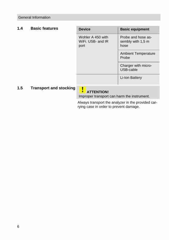
1.4 Basic features Device Basic equipment
Wohler A 450 with WiFi. USB- and IR port
Probe and hose as-sembly with 1,5 m hose
Ambient Temperature Probe
Charger with micro-USB-cable
Li-Ion Battery
1.5 Transport and stocking ATTENTION!
Improper transport can harm the instrument.
Always transport the analyzer in the provided car-rying case in order to prevent damage.
General Information
7
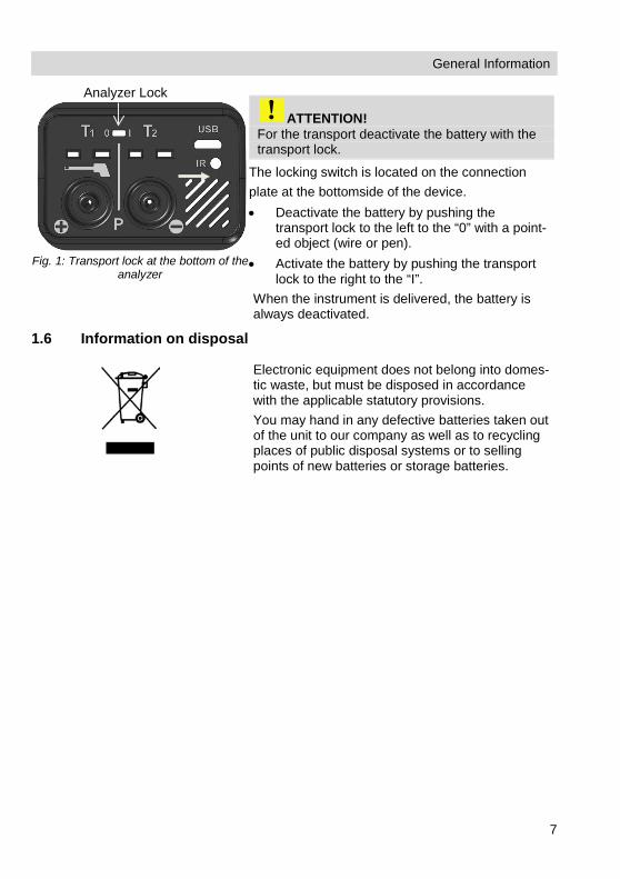
Fig. 1: Transport lock at the bottom of the
analyzer
ATTENTION! For the transport deactivate the battery with the transport lock.
The locking switch is located on the connection plate at the bottomside of the device. • Deactivate the battery by pushing the
transport lock to the left to the “0” with a point-ed object (wire or pen).
• Activate the battery by pushing the transport lock to the right to the “I”.
When the instrument is delivered, the battery is always deactivated.
1.6 Information on disposal
Electronic equipment does not belong into domes-tic waste, but must be disposed in accordance with the applicable statutory provisions. You may hand in any defective batteries taken out of the unit to our company as well as to recycling places of public disposal systems or to selling points of new batteries or storage batteries.
Analyzer Lock

General Information
8
1.7 Manufacturer Wohler Technik GmbH Wohler-Platz 1 33181 Bad Wünnenberg Tel.: +49 2953 73-100 Fax: +49 2953 73-96100 E-Mail: [email protected]
1.8 Important information
ATTENTION! In order to ensure the quality of the application and the measurement result, the ana-lyser may only be used with original Wohler accessories and original Wohler spare parts. This applies in particular to legally regulated measurement tasks
ATTENTION! Do not expose the instrument to moist flue gas, if it has been exposed to temperatures below 0°C for a certain time. This may harm the instrument.
ATTENTION! The instrument is equipped with strong magnets to fix it during the measurement. The magnetic field may harm heart pacemakers, hard disks, data mediums, magnetic stripe cards, controls etc. Keep sufficient distance to magnet-sensitive objects.
ATTENTION! Occasional measurements on cogeneration units (maximum 50 measurements) are permitted due to an internal NOX-filter. If you do measurements on cogeneration units more frequently, please use the external Wohler CHP-Filter, see accessory. When measuring in flue gases of a cogeneration unit, the NOx concentration might be multiple times higher, than in the flue gases of a typical small-scale furnace. An early loss of the cross-insensitivity of the CO-sensor on NOx is perceived as an overload and therefore not covered by your warranty.

Specifications
9
2 Specifications 2.1 Readings
Oxygen (O2) concentration in flue gas
Display Volume % referenced to dry flue gas
Measurement principle
electrochemical sensor
Range 0.0 to 21.0 %
Accuracy ± 0.3 Vol. -%
Carbon monoxide (COV 10,000 ppm) in flue gas (only Wohler A 450)
Display Volume ppm referenced to dry flue gas
Measurement principle
Electrochemical sensor, not H2 compensated
Range 0 to 10,000 Vol. ppm, resolution 1 Vol.-ppm
Accuracy ± 20 ppm (< 400 ppm), otherwise 10 % of reading (if H2 < 5% of reading)
Carbon monoxide (COV 5,000 ppm) in flue gas (only Wohler A 450 L)
Display Volume ppm referenced to dry flue gas
Measurement principle
Electrochemical sensor, not H2 compensated
Range 0 to 5,000 Vol. ppm, resolution 1 Vol.-ppm
Accuracy ± 40 ppm (< 400 ppm), otherwise 10 % of reading
Specifications
10
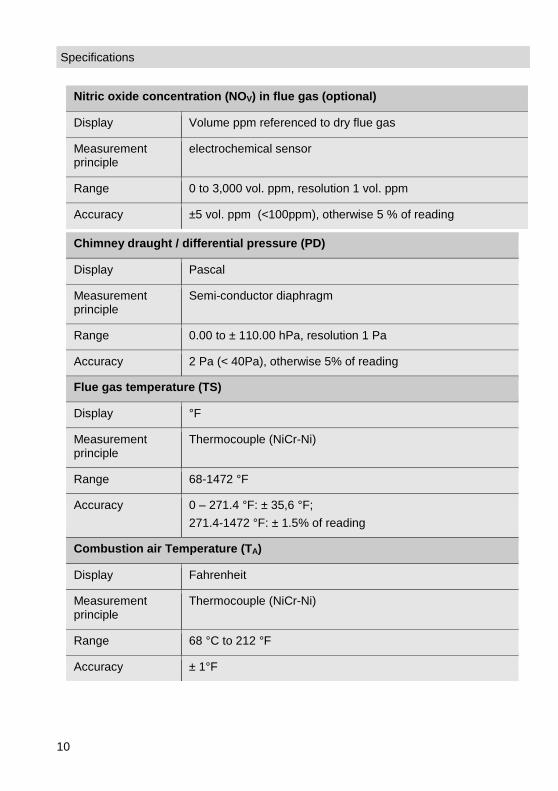
Nitric oxide concentration (NOV) in flue gas (optional)
Display Volume ppm referenced to dry flue gas
Measurement principle
electrochemical sensor
Range 0 to 3,000 vol. ppm, resolution 1 vol. ppm
Accuracy ±5 vol. ppm (<100ppm), otherwise 5 % of reading
Chimney draught / differential pressure (PD)
Display Pascal
Measurement principle
Semi-conductor diaphragm
Range 0.00 to ± 110.00 hPa, resolution 1 Pa
Accuracy 2 Pa (< 40Pa), otherwise 5% of reading
Flue gas temperature (TS)
Display °F
Measurement principle
Thermocouple (NiCr-Ni)
Range 68-1472 °F
Accuracy 0 – 271.4 °F: ± 35,6 °F; 271.4-1472 °F: ± 1.5% of reading
Combustion air Temperature (TA)
Display Fahrenheit
Measurement principle
Thermocouple (NiCr-Ni)
Range 68 °C to 212 °F
Accuracy ± 1°F

Specifications
11
2.2 Calculated Values
Calculated Value Explanation
Efficiency /SL Efficiency and losses in accordance to ASME standards
ETA/QS Efficiency and losses in accordance to European standards (0.0 to 120%)
CO2 in Vol. -% Range 0 – CO2max, resolution 0.1 %
COc, SO2c; NOc, NO2C air free (corrected) Default: 0% (oil and gas).
Dpt
°C Dew Point in the flue gas
Medium soot level Soot number ± 0.1
Excess air coefficient Lambda λ (e.g. 1,25 when the excess of air is 25%)
Con Condensate quantity in condensing conditions
Toxication index GI CO/CO2
Air velocity 0.1 to 130 m/s, resolution < 0.1 m/s, for the measurement of the ventilation loss (heating check)

Specifications
12
2.3 Technical Data
Description Data
Power supply Lithium-Ion, rechargeable battery 3.7 V, 2,250 mAh, charg-es via USB
Battery Operating time Approx. 6 h (depends on operating status and display illu-mination)
Charging time for a full charge
Approx. 3 hours
Storage Temperature 4-122 °F
Operation temperature 41-104°F
Weight 1.5 lbs
Dimensions 6 x 4 x 1.5 inches
Length of the probe-hose
5 ft
Component Explanation
13
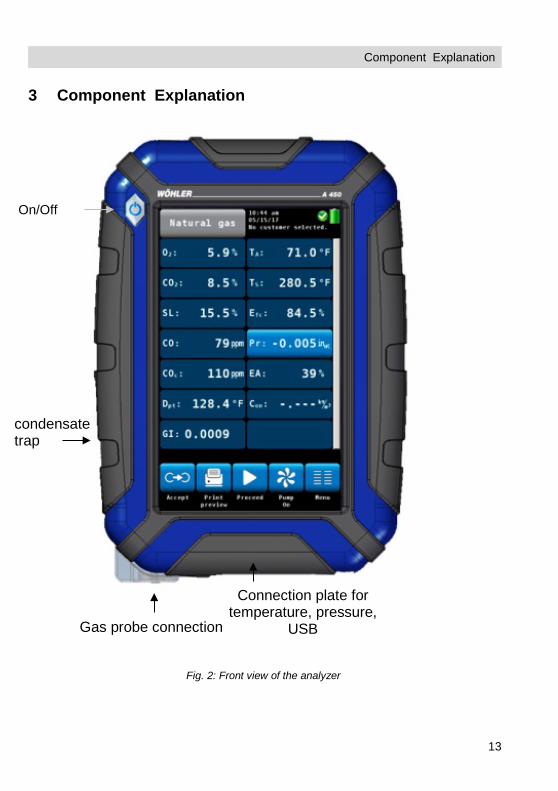
3 Component Explanation
Fig. 2: Front view of the analyzer
On/Off
Gas probe connection
Connection plate for temperature, pressure,
USB
condensate trap

Component Explanation
14
Connections on the bottom of the unit 1 Lock Battery, cf. chapter 4.1 2 USB-port for data transfer and charging 3 IR interface for thermal printer 4 Gas temperature 5 Ambient Air Temperature 6 Positive pressure 7 Negative pressure 8 Speaker for alarm signals
2
3
4 5
6 7
8
6 7
1
Fig. 3: Connection plate on the bottom of the unit
Component Explanation
15
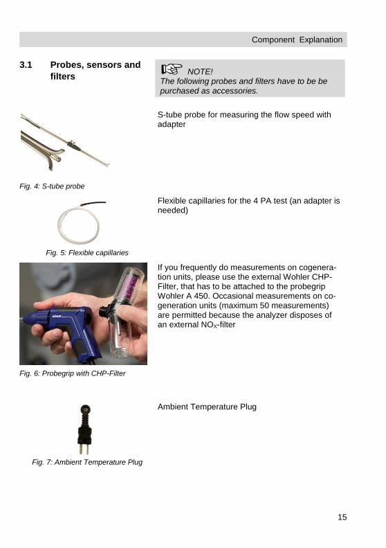
3.1 Probes, sensors and filters NOTE!
The following probes and filters have to be be purchased as accessories.
Fig. 4: S-tube probe
S-tube probe for measuring the flow speed with adapter
Fig. 5: Flexible capillaries
Flexible capillaries for the 4 PA test (an adapter is needed)
If you frequently do measurements on cogenera-tion units, please use the external Wohler CHP-Filter, that has to be attached to the probegrip Wohler A 450. Occasional measurements on co-generation units (maximum 50 measurements) are permitted because the analyzer disposes of an external NOX-filter
Fig. 7: Ambient Temperature Plug
Ambient Temperature Plug
Fig. 6: Probegrip with CHP-Filter

Component Explanation
16
Fig. 8: combustion air temperature probe
Combustion air temperature probe Wohler A 450 , 185 mm
Fig. 9
Hoses for pressure measurement

Component Explanation
17
3.2 Display
The Wohler A 450 is operated via Touchscreen. The measurement menu is similar to the one of a smartphone. A fingertip on the icon starts the correspondent measurement mode. The active icons are graphically emphasized. If there is a bar on the right of the display, the display can be scrolled by pulling it with the finger.
Fig. 10: Display details
The display is divided into different segments: The fuel is shown in the topline on the left. The currently selected customer and measurement mode are shown on the right of the fuel. Date and time, system diagnostic status and bat-tery level are shown on the right. The readings segment displays the current read-ings. Click on PR key for zeroing the pressure sensor.
NOTE! The user can set up the display according to his needs. He can arrange the readings and chose the units. Go to the setup-menu and select "change units" (see chapter 7.6).
The icon segment offers different options. These options are explained in chapter 5.3.1

Component Explanation
18
3.3 Gas sampling path Wohler A 450
Fig. 11: Gas sampling path Wohler A 450 with flue gas probe 250 mm The sensors are protected against condensate by a three-step-filter conditioning: The first step is the coarse filter in the probe handle. Most of the particles will be re-moved from the sample. After that the gas passes the condensate trap, where the gas is cooled by a spiral and the condensate is collected. The second step is an exchangeable cotton filter. Fine particles and rests of water will be removed from the sample. The last step is the Water Stop Filter. This filter will not allow any kind of moisture to pass. The filter will clog automatically in contact with water, so that the sensors are protected against moisture. The flue now passes each sensor module (O2, CO and NO). During this process, the CO-sensor is additionally protected by the internal NOX filter.

Getting started
19
4 Getting started 4.1 Activating the battery
Fig. 12: Battery lock to the right: Battery activated; Battery lock to the left: Battery locked
• Before first use: Activate the battery by push-ing the battery lock with a sharp object (paper clip or other slim wire) to the right, cf. adjacent figure.
The locking switch is located on the connection plate at the bottom of the unit.
4.2 Tightness test
Fig. 13: Ball pump
Before the tightness test connect the gas probe. Proceed as follows: • Squeeze the ball pump (part 1). • Plug the ball pump (part 1) on the gas probe
(part 2) • Release the ball pump. After the ball pump has been released, it may not fill with air or only fill very slowly. Otherwise the connection is not tight.
ATTENTION! Never plug the ball pump on the gas probe and squeeze it afterwards. In this case the draft probe will be damaged.

Getting started
20
4.3 Charging the battery
Fig. 14: USB port
The battery indication is displayed in the upper right corner of the screen. A fully charged battery is shown as a solid green battery symbol. If the battery symbol is red, the display illumina-tion is automatically reduced to save energy. In this case, charge the battery or use the Wohler A 450 in mains operation. • Before you plug the USB-recharger into the
outlet, connect it with the analyzer. To do so, plug the USB connector of the recharger to the USB port at the bottom of the analyzer.
During the charging process a jack-symbol will blink in the upper right part of the screen and the ON/OFF key will blink red.
NOTE! Recharging empty batteries can take up to 7 hours. You can still go on measuring while battery charging is in progress. In this case charging time will be longer.
After the charging time has finished the ON/OFF key will shine red.
WARNING! Risk of electrical shock! Never touch the power supply with wet hands! Protect the power supply against water and mois-ture! Do not unplug the recharger by pulling the cable! Do not use the power supply when the voltage requirements of the recharger and the supply do not match!

Getting started
21
4.4 Connecting the flue gas probe
Fig. 15: Bottom oft he device
Fig. 16: Gas probe – gas hose (1), pres-
sure hose (2), temperature plug (3)
• Attach the wide gas hose to the gas connec-tion (1)
• Attach the small gas hose to the positive pres-sure connection (2) .
• Attach the temperature plug tot he tempera-ture connection T1 (3). Please observe the correct polarity.
1
2
3
1 2 3

Using the Analyzer
22
5 Using the Analyzer
ATTENTION! Before use, always test if the instrument is in a proper condition Perform a tightness test according to chapter 4.2.
5.1 Turning the analyzer on and off
• Press the ON/OFF key shortly to turn ON the analyzer. The startup screen will appear.
• Long press the ON/OFF-key for 3 seconds to turn the analyzer off.
5.2 Calibration
Fig. 17: Sensor calibration
Immediately after the device has been switched on, the Wohler A 450 will start to calibrate the sensors with fresh air. This calibration process will take 60 sec.
Note! The gas probe may not be located in the flue gas tube during the calibration.
During the calibration process 5 icons will appear in the display. • Clic on an icon to open the correspondent
menu.
Restart
Starts the calibration again.

Using the Analyzer
23
Diagnosis
Click on the "diagnosis" icon to finish the hotspot search and enter the analyzers self diagnosis mode (see chapter 0).
Customers
Click on the "Customers" icon to enter the Cus-tomers menu. The Customers Menu allows to set up a new costumer or preselect a customer before the measurement. After the measurement the measured data can be stored to the customer folder, see chapter 6.3.
Data Exchange
Click on the "Data Exchange” icon to finish the hotspot search and enter the data exchange mode. In this mode data can be exchanged be-tween the Wohler A 450 and the PC via USB or Bluetooth.
Menu
Opens the main menu. Only those submenus are available which can be started without hotspot search.

Using the Analyzer
24
5.3 Measuring
After the 60 seconds calibration procedure the analyzer will display the main combustion efficien-cy test screen.
5.3.1 Readings screen
Al readings (measured and computed values) will be shown continuously in the readings segment.
NOTE! The user can change the order of the values. He can also select the unit of some of the values (see chapter 7.6) Up to 14 values can be shown on screen. The following screen is only an example.
Fig. 18: Readings segment
Using the Analyzer
25
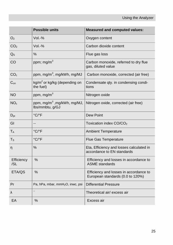
Possible units Measured and computed values:
O2 Vol.-% Oxygen content
CO2 Vol.-% Carbon dioxide content
QS % Flue gas loss
CO ppm; mg/m3 Carbon monoxide, referred to dry flue gas, diluted value
COc ppm, mg/m3, mg/kWh, mg/MJ Carbon monoxide, corrected (air free)
Con kg/m2 or kg/kg (depending on the fuel)
Condensate qty. in condensing condi-tions
NO ppm, mg/m3 Nitrogen oxide
NOc ppm, mg/m3 ,mg/kWh, mg/MJ, lbs/mmbtu, g/GJ
Nitrogen oxide, corrected (air free)
Dpt °C/°F Dew Point
GI -- Toxication index CO/CO2
TA °C/°F Ambient Temperature
TS °C/°F Flue Gas Temperature
ƞ % Eta, Efficiency and losses calculated in accordance to EN standards
Efficiency /SL
% Efficiency and losses in accordance to ASME standards
ETA/QS % Efficiency and losses in accordance to European standards (0.0 to 120%)
Pr Pa, hPa, mbar, mmH2O, inwc, psi Differential Pressure
λ -- Theoretical air/ excess air
EA % Excess air

Using the Analyzer
26
5.3.2 Selecting the fuel
Fig. 19: Fuel options
The selected fuel is shown in the topline on the left of the readings screen. • Click on the fuel key to enter the fuel options
menu. Optional fuels as below: Natural gas, Fuel Oil 2, Fuel Oil 4, Fuel Oil 6, Bio-fuel, LPG, Propane, Kerosene, Digester Gas, Coal, Wood, Pellets and four user defined fuels
NOTE! To see all fuels scroll by drawing your finger over the screen.
• Click on a fuel. The fuel will be selected for the next measurement.
• After turning off and on the analyzer, the last selected fuel will be active again.
5.3.3 Setting the fuel param-eters
The reference oxygen and the Lamda threshold values of all fuels can be individually set. All parameters can be set for the user defined fuels. • Click on the “Fuel data” icon to control or
change the fuel parameters. The “Fuel data” icon will turn green.
• Click on the fuel whose parameters are to be changed.
• The analyzer enters the fuel parameter menu. Change the parameters and confirm with "OK".

Using the Analyzer
27
5.3.4 Options In the readings screen a click on one of the icons at the bottom offers the following options:
Graph
• A click on the Graph icon generates a graph of the measured values.
Fig. 20: Graph of the CO readings
• Above the graph the measured value, which is presented in the graph, is indicated as a num-ber.
• Select the value to be presented with the arrow keys.
The options in the graph mode are as follows: • Click New to start a new measurement. • Click Stop to stop the measurement and hold
the values. • Click Back to return to the numeric screen.
Copy readings
• Click on the “Copy readings” icon to copy the readings into the clipboard. The “Copy val-readings” icon will appear in the top right screen.
This way the user can save the readings in case of an early switching off of the burner. When the user continues the measurement after having copied the readings to the clipboard, he can de-cide if he wants to save the actual readings or those of the clipboard.
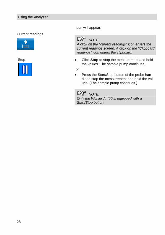
Clipboard readings
• To save the readings of the clipboard, stop the measurement. When the measurement is stopped click on "Clipboard readings".
In the clipboard screen, the "Current readings"
Using the Analyzer
28
icon will appear.
Current readings
NOTE! A click on the "current readings" icon enters the current readings screen. A click on the "Clipboard readings" icon enters the clipboard.
Stop
• Click Stop to stop the measurement and hold the values. The sample pump continues.
or • Press the Start/Stop button of the probe han-
dle to stop the measurement and hold the val-ues. (The sample pump continues.)
NOTE! Only the Wohler A 450 is equipped with a Start/Stop button.

Using the Analyzer
29
Pump off
• Click on "Pump OFF" to turn off the gas pump and the CO protection pump.
Pump on
• Click on "Pump on" to turn on the gas pump.
Accept
The “Accept” icon will only appear if the meas-urement is stopped. • Click on the "Accept" icon to enter the Read-
ings menu. In the Readings menu you can save the readings in a customer folder (see chapter 6).
Proceed
• Click on "Proceed" to continue the measure-ment.
Readings Menu
30
6 Readings Menu
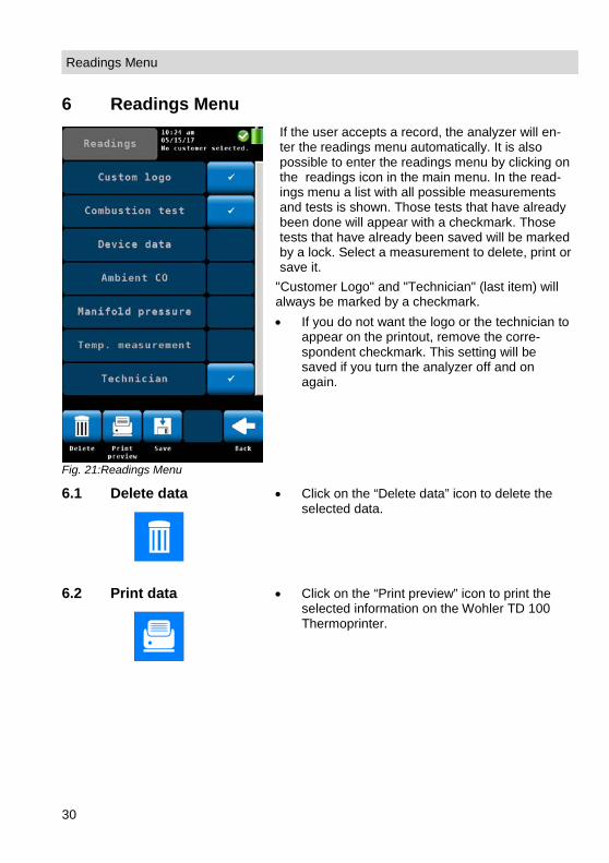
Fig. 21:Readings Menu
If the user accepts a record, the analyzer will en-ter the readings menu automatically. It is also possible to enter the readings menu by clicking on the readings icon in the main menu. In the read-ings menu a list with all possible measurements and tests is shown. Those tests that have already been done will appear with a checkmark. Those tests that have already been saved will be marked by a lock. Select a measurement to delete, print or save it.
"Customer Logo" and "Technician" (last item) will always be marked by a checkmark. • If you do not want the logo or the technician to
appear on the printout, remove the corre-spondent checkmark. This setting will be saved if you turn the analyzer off and on again.
6.1 Delete data
• Click on the “Delete data” icon to delete the selected data.
6.2 Print data
• Click on the “Print preview” icon to print the selected information on the Wohler TD 100 Thermoprinter.

Readings Menu
31
Fig. 22: Print Preview
A print preview will appear. • Click on the “Cancel” icon, if you do not want
to print the information shown in the preview or • Click on the “Print” icon to start the printout.
Fig. 23: Printing the readings of the Wohler A 450 on the Thermoprinter
Wohler TD 100.
NOTE! Place the printer with the IR receiver toward the IR interface of the analyzer.
After printing, the analyzer will enter the meas-urement mode again.
6.3 Save data in the cus-tomer menu.
• Click on the “Save” icon to save a customer record. The analyzer will enter the customer menu. Create a new customer folder or save the record in an existing customer folder.
• Proceed as described in chapter 8.

Menu
32
6.4 Save data with the “Quick save” option
Fig. 24: Data record saved with the quick save function
If the quick save option is activated in the Setup-Menu (see Chapter 7.6), the analyzer will auto-matically save the measurement records under a new customer. The customer name will be the measurement date and the measurement time. • After the measurement click on “Accept”. • Click on the “Save” icon to save a customer
record.
7 Menu
Menu
• Click on the main “Menu” icon to enter the main menu.
Fig. 25: Main menu
In the main menu you can select the different measurement options or the setup-menu or the calibration menu. The lower icon bar shows the “Customer” (see chapter 8) and the “Readings” icon (see chapter 6). • Click on the “Back” icon to return to the normal
measurement mode.
Menu
33
7.1 Device data
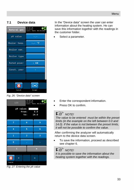
Fig. 26: “Device data” screen
In the “Device data” screen the user can enter information about the heating system. He can save this information together with the readings in the customer folder. • Select a parameter.
Fig. 27: Entering the ph value
• Enter the correspondent information. • Press OK to confirm.
NOTE! The value to be entered must be within the preset limits (in the example on the left between 0.0 and 14.0). If the value is not between the preset limits, it will not be possible to confirm the value.
After confirming the analyzer will automatically return to the device data screen. • To save the information, proceed as described
see chapter 6.
NOTE! It is possible to save the information about the heating system together with the readings.

Menu
34
7.2 Ambient CO
Fig. 28: Ambient CO
The option 'Ambient CO' offers a graphical assist-ed ambient CO test. The current ambient CO concentration is shown over the elapsed measurement time. The figure on the left shows an 'Ambient CO' test over a time period of 230 seconds and the current CO level is 2 ppm. The options during the ambient CO test are as follows: • Cancel (left icon): click the left key to exit
without performing an “Ambient CO” test and return to the main menu.
• New: Start a new “Ambient CO” test • Option “CO=0”: click to zero-out the CO sen-
sor offset reading. • To evaluate the test click on "Not OK" or "OK".
The analyzer will enter the data menu where you can save and/or print the information.
NOTE! Due to temperature effects and aging of the CO sensor it is possible that the 0 ppm offset level changes. Check regularly in clean air that the am-bient CO level is reading zero. If the reading is not zero in clean air, click the 'CO=0' key to zero-out the readings.
7.3 Manifold Pressure
Fig. 29: Pressure connector
• To perform a manifold pressure test click on the “Manifold Pressure” icon in the main menu screen.
• Connect a pressure hose to the negative Pressure connector at the bottom of the ana-lyzer .

Menu
35
Fig. 30: Manifold Pressure mode screen
The options in the “Manifold Pressure” mode screen are: • Option “Cancel”: click “Cancel” to exit the
“Manifold Pressure” test and return to the main menu.
• Option “New”: click “New” to clear the graph and all captured readings and start a new “Manifold Pressure” test.
• To evaluate the test click on "Not OK" or "OK". The analyzer will enter the data menu where you can save and/or print the information.
Menu
36
7.4 Temperature
Measurement
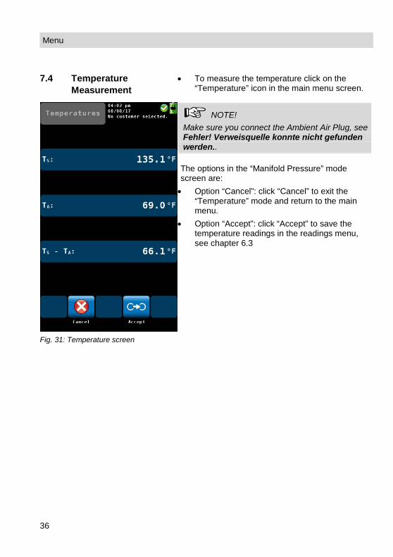
Fig. 31: Temperature screen
• To measure the temperature click on the “Temperature” icon in the main menu screen.
NOTE! Make sure you connect the Ambient Air Plug, see Fehler! Verweisquelle konnte nicht gefunden werden..
The options in the “Manifold Pressure” mode screen are: • Option “Cancel”: click “Cancel” to exit the
“Temperature” mode and return to the main menu.
• Option “Accept”: click “Accept” to save the temperature readings in the readings menu, see chapter 6.3

Menu
37
7.5 Tuning Guide
In the "Tuning Guide" menu all combustion test related readings are presented in a graph over the excess air. The tuning guide offers an advanced guidance to the technician to properly adjust the burner.
Tuning Guide
• In the main menu, click on the “Tuning guide” icon.
Fig. 32: Tuning Guide
The graph for adjusting the burner will be shown. The current reading is marked with a red box and any former reading is tracked with a green line. The 'Green Zone' indicates the best combustion performance excess air range of the burner. The range is user changeable for any selected fuel (see chapter 5.3.3). The figure on the left shows that the CO content in the flue gas increases significantly when the available excess air decreases. • Click on "New" to delete the graph and start a
new one. • Click on "Back" to return to the main menu.

Menu
38
7.6 SETUP
In the setup-menu the user can adjust the screen or the measurement process. In order to see all parameters, scroll to the top or the bottom of the screen by sweeping the left column with a finger.
SETUP
• In the main menu, click on the setup icon.
Fig. 33: Setup menu, the scroll bar shows that there are more parameters available.
• The analyzer will enter the setup menu. 7 of the 13 parameters are displayed.
• Sweep the left column with a finger to navi-gate through the setup menu.
• To change a parameter click on the corre-spondent key in the right column.
• Click on "OK" to save the new setting before leaving the setup menu.
The following options are available:

Menu
39
7.6.1 Option "Date" Change the current date of the analyzer's internal calendar with day, month and year.
7.6.2 Option "Time" Change the current time of the analyzer's internal clock (24 h mode) with hours and minutes.
7.6.3 Option “Date format” Select a date format. Possible options are dd.mm.yyyy / mm.dd.yyyy
7.6.4 Option “Time format” Select a time format. Possible options are 24 h / 12 h
7.6.5 Option "Brightness" Change the brightness of the display in 9 steps. • Click on the upwards arrow to set the back-
light brighter, click on the downwards arrow to set the display darker.
NOTE! A bright display will increase the power consump-tion.
7.6.6 Option "Buzzer" Change the sound of the buzzer. The options are Standard, Loud or Off,
7.6.7 WLAN configuration
Fig. 34: WLAN configuration: Mode
• In the main menu select Setup > WLAN-configuration
• Select between 3 WLAN modes: Off, Direct connection and Router con-nection.
Mode „OFF“ It is not possible to use the Wohler A 450 App.

Menu
40
Mode „Direct connection“
Fig. 35: WLAN configuration – Direct connection
If you do not have access to a router network, select Direct Connection. In this case the analyzer will create its own wire-less network. You can connect your mobile de-vice (tablet or smartphone) to the analyzer’s network.
Note! After you have seleced „Direct connection“ and confirmed with OK, in the upper display “WLAN ready” will appear (alternating with the selected customer).
Network name
The name of the network of the analyzer is as follows: WoehlerA 450/serial number
Encryption
Select the channel where the Wohler A 450 sends. You can select a channel where there are few other devices.
NOTE! Normally it is not necessary to change this set-ting.
Key
Network password that you have to enter in your mobile device. The password (factory set-ting) is 12345678. • Click on „Key“ to change the password. • Enter a new password (min. 8 figures, max.
24 figures)

Menu
41
• Confirm with OK.
Note! You have to confirm the settings with OK, be-fore you can establish the WLAN connection to your mobile device.
Mode „Router Connection“
Fig. 36: Router connection
• Select „Router connection“ if there is a per-manent WLAN network in the house that you want to use.
• Click on Network name. After a few seconds a list of all available net-works will appear in the display. • Click on the network that you want to use. • If the network is protected with a password,
enter the passwort (the password must have at least 8 characters) Another possibility to enter the password is to click on “Key” in the WLAN-configuration-display.
• Confirm with OK. The analyzer will connect to the router network now.
Encryption Encryption of your router. It is possible to disa-ble the encryption by setting Encryption > None. In this case everybody can log on to the network. For this reason we recommend not to change the encryption settings.

Menu
42
Fig. 37: „WLAN connected“ appears in the upper display, alternating with the selected customer
HINWEIS! After the analyzer has been connected to the router network and you have confirmed your settings with OK, in the upper display the WLAN icon will appear and the text “WLAN connect-ed”.
• Connect your mobile device to the same router network.
• Open the Wohler A 450 App. • In the App, click on “Connect device”. The App will now connect to the Wohler A 450.

Menu
43
7.6.8 Option “Quick save”
If the quick save option is activated, the analyzer will automatically save the measurement records under a new customer. The customer name will be the measurement date and the measurement time. (see Chapter 6.4)
Default: “Quick save” off
7.6.9 Option "Customer by" Change the order of the saved records between customer name or number.
7.6.10 Option "Device by" Change the order of the saved records between fireplace name or number.
7.6.11 NOx calculation Here the user can enter the NO2 percentage on which the calculation of the NOX value is based. The default NO2 percentage is 5 %. Only change the NO2 factor, if the boiler manufacturer recom-mends it.
7.6.12 Filter warning If a filter warning appears in the display, you can delete it with this option.
7.6.13 Signals The user can set up the reading segment accord-ing to his needs. • Click on "change" to enter the signals menu. • In the left column (Display) click on the key
that has to be substituted . The key will turn to green. • In the right column (signals), click on the key
that shall substitute the green key in the left column.
• This key will now appear in the left column instead of the green key.
• To change a unit, in the left column (display) click several times on the key whose unit has to be changed. You will find the possible units in the table of chapter 5.3.1.
The icons in the footer have the following function: • Cancel: Escape without saving the modifica-
tions. • Restore defaults: Reset to factory settings. • Remove signal: Remove a value from the

Customer data
44
Fig. 38: Configuration of the readings segment.
readings segment. • OK: Confirm the modification and return to the
Setup menu.
7.6.14 Customer Logo • Click on "Change", enter your logo and con-firm with OK.
Your logo will now appear on all printouts.
7.7 Calibration In the calibration menu a digitally assisted calibra-tion of all sensors can be done. To open the cali-bration menu it is necessary to enter a password. For this reason unauthorized persons cannot cali-brate the analyzer and incorrect settings are avoided. The calibration of the analyzer is allowed to trained personnel ONLY. Please contact Wohler for more information.
8 Customer data The analyzer allows to save the values in different fireplace folders. You can assign a fireplace or several fireplaces to a customer. Each customer and each fireplace has its own number.

Customer data
45
8.1 Set up a new cus-tomer
• There are two possibilities: 1. Go to the main menu and click on the Cus-tomers icon or 2. Click on the customer icon during the search for the hotspot.
• Click on the New Customer Icon to create a New Customer folder.
Fig. 39:Creating a new customer folder
• Enter the name and the number of the cus-tomer and the device/fireplace. Confirm with OK.
8.2 Save records
• In the Readings menu (see chapter 6) click on the Save-icon to save all marked measure-ment records under a customer and a fire-place. The analyzer will enter the customer menu.
The customer menu shows a list of all customers.

46
Fig. 40: Selecting a customer in the customer menu.
• Click on a customer. The analyzer will enter the Devices/fireplace menu.
• Click on a device. The analyzer will save the marked measurement records under this device.
8.3 Search function : customer,device, customer number, device number
• In the customer menu click on the “Find cus-tomer” iconcus.

47
Fig. 41: Customer research
• Enter any part of the customer name. At the bottom of the display the first result will be shown. Click on the arrow key to see the other results and select the customer.
After selecting the customer, search the device in the same way. • Click on the icon „Find device“.
Research by name or by number
Note! In the setup menu you have the possibility to se-lect if you want to search the customer/device by name or by number.
48
8.4 New customer
• Click on the New customer icon in the main menu to create a new customer folder.
8.5 Delete customer
In the customer menu it is possible to cancel a selected customer. • Click on the "Delete customer" icon. The icon
will become green. • Select the customer to be canceled and con-
firm.
8.6 Delete all
• To delete all customers from the analyzer click on the "Delete all" icon.
9 Data exchange with the PC
With the Wohler A 450 Sorftware it is possible to exchange the data with the PC via USB or WLAN.
NOTE! The data transfer and the functions of the Software are explained in the Manual Wohler A 450 PC Software.
10 Troubleshooting
Problem Possible reason Solution
Empty battery icon Battery is empty. Recharge battery.
No reaction of the analyzer Reset: Push the transport lock to the right and then to the left again (see Feh-ler! Verweisquelle konn-te nicht gefunden wer-den.)
The Flue gas temperature is not shown in the display
The temperature plug is not plugged in correctly.
Plug in the temperature plug, see Fehler! Verweis-quelle konnte nicht ge-funden werden..
Maintenance
49
11 Maintenance Proper operation of the Wohler A 450 requires regular maintenance.
11.1 Maintenance work Interval Maintenance work
If filter warning appears in the display.
Change water-stop filter
Once a year Return analyzer for check and calibration to a Wohler certi-fied service station
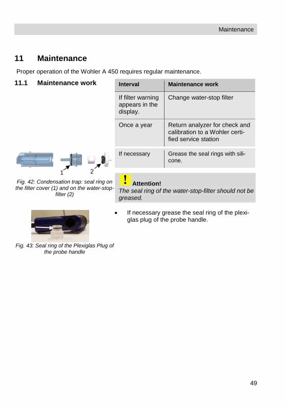
Fig. 42: Condensation trap: seal ring on the filter cover (1) and on the water-stop-
filter (2)
If necessary Grease the seal rings with sili-cone.
Attention! The seal ring of the water-stop-filter should not be greased.
Fig. 43: Seal ring of the Plexiglas Plug of
the probe handle
• If necessary grease the seal ring of the plexi-glas plug of the probe handle.
1 2

Maintenance
50
11.2 Removing condensate
The condensate will be collected in the condensate trap. To remove the condensate follow the steps below:
Fig. 44: Pulling the condensate trap out
of the analyzer
• Turn the condensate 90° to the left and pull it out of the analyzer.
Fig. 45: Condensate trap
1. Probe connection of the condensate trap 2. Condensate panel (inside the condensate
trap) 3. Condensate bin 4. Seal ring 5. Filter cover 6. Cotton filter 7. Seal ring of the water stop filter 8. Water stop filter
• Turn the filter cover a little, so that you can pull it from the condensate bin.
CAUTION! The condensate panel always has to stay inside the condensate bin.
• Spill the condensate out of the cup.
2 7 8 5 6 4 3 1
Maintenance
51
11.3 Changing the filters If the cotton filter or the water stop filter are clogged, a filter warning will appear at the top of the display. • In this case check the filter and change it if
necessary. After the filter has been changed the warning will disappear. If this is not the case, you can delete the filter warning in the setup-menu, see chapter 7.6.12.
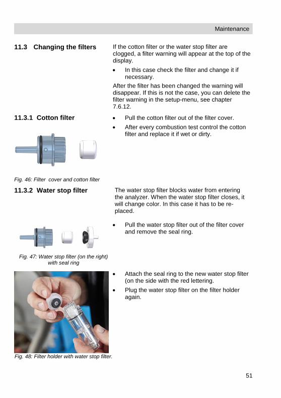
11.3.1 Cotton filter
Fig. 46: Filter cover and cotton filter
• Pull the cotton filter out of the filter cover. • After every combustion test control the cotton
filter and replace it if wet or dirty.
11.3.2 Water stop filter The water stop filter blocks water from entering the analyzer. When the water stop filter closes, it will change color. In this case it has to be re-placed.
Fig. 47: Water stop filter (on the right)
with seal ring
• Pull the water stop filter out of the filter cover and remove the seal ring.
Fig. 48: Filter holder with water stop filter.
• Attach the seal ring to the new water stop filter (on the side with the red lettering.
• Plug the water stop filter on the filter holder again.
Maintenance
52
11.4 Sensor diagnosis and replacement
Electrochemical gas sensors are subject to wear. The life of the measuring sensors will be determined by numerous outside parameters such as the care provided for the ana-lyzer (removal of condensate), the frequency of use and regular maintenance. This explains why the average life of measuring sensors will be determined by specific experience. O2 -sensor 4 years CO-sensor 4 years
The sensors can be changed in the factory or by an authorized service point. The user can also change the sensors himself. The Wöhler A 450 has an advanced electronic
self diagnosis program. You can enter the diagnosis screen directly after having switched on the analyzer during self check and calibration .
Diagnosis
• Click on the Diagnosis icon.
Maintenance
53
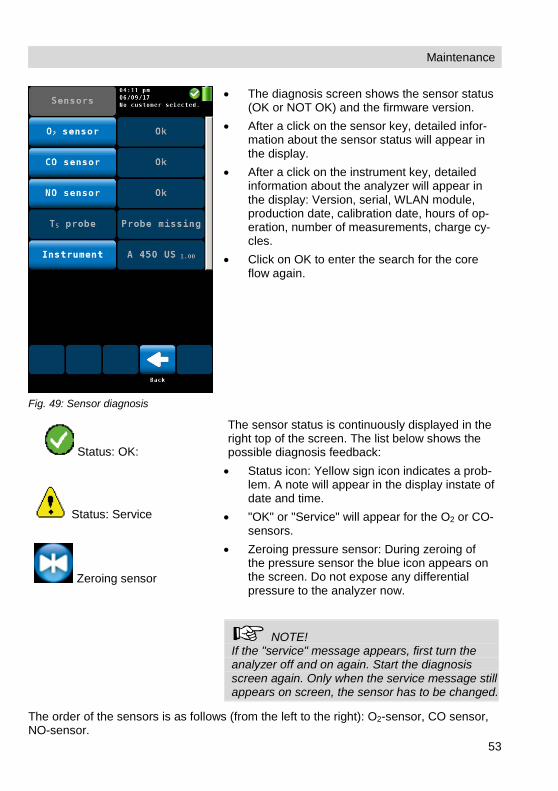
Fig. 49: Sensor diagnosis
• The diagnosis screen shows the sensor status (OK or NOT OK) and the firmware version.
• After a click on the sensor key, detailed infor-mation about the sensor status will appear in the display.
• After a click on the instrument key, detailed information about the analyzer will appear in the display: Version, serial, WLAN module, production date, calibration date, hours of op-eration, number of measurements, charge cy-cles.
• Click on OK to enter the search for the core flow again.
Status: OK:
Status: Service
Zeroing sensor
The sensor status is continuously displayed in the right top of the screen. The list below shows the possible diagnosis feedback: • Status icon: Yellow sign icon indicates a prob-
lem. A note will appear in the display instate of date and time.
• "OK" or "Service" will appear for the O2 or CO-sensors.
• Zeroing pressure sensor: During zeroing of the pressure sensor the blue icon appears on the screen. Do not expose any differential pressure to the analyzer now.
NOTE! If the "service" message appears, first turn the analyzer off and on again. Start the diagnosis screen again. Only when the service message still appears on screen, the sensor has to be changed.
The order of the sensors is as follows (from the left to the right): O2-sensor, CO sensor, NO-sensor.

Maintenance
54
NOTE! If the user himself replaces the sensors, the sensor date shown in the diagnosis menu will update automatically.
Replace the sensor as follows:
Fig. 50: Bottom of the device - Open the cover by loosening the cross-head screws .
• Power off the analyzer. • Loosen the 2 screws of the cover with a cross-
headed screwdriver. • Remove the cover from the analyzer.

Maintenance
55
Fig. 51:Bottom of the analyzer with cover removed
Fig. 52: Sensor support removed from the analyzer
• Cautiously remove the transparent hose of the gas path from the holders.
• Cautiously remove the sensor support from the analyzer.
NOTE! The hose of the gas path can stay connected to the gas pump.
Hose of the gas path
sensor sup-port
O2 CO
Battery Holder
NO

Maintenance
56
Replacing the O2 Sensor
Fig. 53: Connector of the O2-sensor removed
• Remove the 2-pin connector of the O2 sensor. • Replace the O2 sensor by a new one. • Plug the new connector to the original place. • Plug the O2 sensor to the board.
NOTE! The hose of the gas path can stay connected to the gas pump.
Changing the CO sensor
• Replace the sensor by a new one. • Plug the CO sensor to the board.
NOTE! After installing a new CO-sensor you must enter the calibration values in the calibration menu, see Fehler! Verweisquelle konnte nicht gefunden werden..
Installing a NO-sensor • It is possible to install an NO-sensor • Plug the NO-sensor to the board in place of
the tamping.
CAUTION! After the NO sensor has been installed, an activa-tion time of 24 hours must be observed. During the activation period the battery must be active, see chapter 4.4.

Maintenance
57
Fig. 54: Sensors plugged to the board. Top down: O2, CO and NO (option)
Fig. 55: Sensor support placed on the sensors and hose of the gas path cor-rectly installed in the holders.
• Place the sensor support on the sensors again.
• Install the hose of the gas path correctly in the holders.
CAUTION! Take care not to bend the hose.
• Replace the cover on the analyzer and fix it with the two screws.

Maintenance
58
Fig. 56: Entering the calibration values in the calibration menu (only CO-sensor)
• After a change of the CO-sensor, you must enter the calibration values in the calibration menu.
• Switch on the analyzer. • In the main menu, click on the calibration icon. • Enter the Code 4798 • Click on Calibrate CO-sensor. • Enter the calibration value Gain. You will find
the gain value printed on the CO-sensor. • Press OK to confirm.

Maintenance
59
11.5 Replacing the battery
WARNING! Incorrect use of the battery can cause injury! Never dispose the battery to fire or high temperatures. Danger of explosion! Liquids can leak out of the battery due to mistreatment. Never touch the liquid. If you get in contact to the liquid remove it with water. If the liquid comes into contact with eyes, rinse with water immediately for 10 minutes and consult a doctor immediately!
11.5.1 Replacing the battery
The Wöhler A 450 is equipped with a rechargeable lithium ion battery 3.6 V, 2250 mAh. Only after a long working period the battery has to be changed. In this case send the analyzer to your dealer or change the battery as follows: • Switch off the analyzer. Open the analyzer as
described before in the chapter "sensor re-placement".
Six-monthly check
60
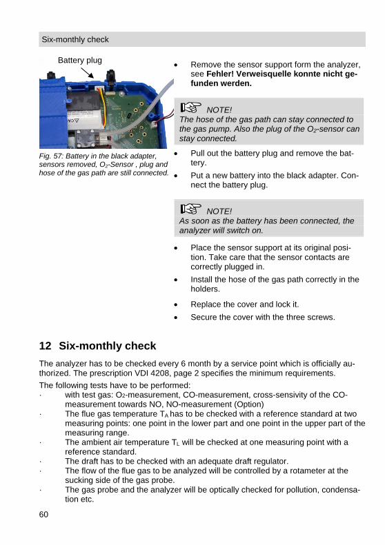
Fig. 57: Battery in the black adapter, sensors removed, O2-Sensor , plug and hose of the gas path are still connected.
• Remove the sensor support form the analyzer, see Fehler! Verweisquelle konnte nicht ge-funden werden.
NOTE! The hose of the gas path can stay connected to the gas pump. Also the plug of the O2-sensor can stay connected.
• Pull out the battery plug and remove the bat-tery.
• Put a new battery into the black adapter. Con-nect the battery plug.
NOTE! As soon as the battery has been connected, the analyzer will switch on.
• Place the sensor support at its original posi-tion. Take care that the sensor contacts are correctly plugged in.
• Install the hose of the gas path correctly in the holders.
• Replace the cover and lock it. • Secure the cover with the three screws.
12 Six-monthly check The analyzer has to be checked every 6 month by a service point which is officially au-thorized. The prescription VDI 4208, page 2 specifies the minimum requirements. The following tests have to be performed: · with test gas: O2-measurement, CO-measurement, cross-sensivity of the CO-
measurement towards NO, NO-measurement (Option) · The flue gas temperature TA has to be checked with a reference standard at two
measuring points: one point in the lower part and one point in the upper part of the measuring range.
· The ambient air temperature TL will be checked at one measuring point with a reference standard.
· The draft has to be checked with an adequate draft regulator. · The flow of the flue gas to be analyzed will be controlled by a rotameter at the
sucking side of the gas probe. · The gas probe and the analyzer will be optically checked for pollution, condensa-
tion etc.
Battery plug

Guaranty and Service
61
13 Guaranty and Service Each Wohler A 450 will be tested in all functions and will leave our factory only after extensive quality control testing. The final control will be recorded in detail in a test re-port and delivered with any unit. If used properly, the warranty period for the Wohler A 450 will be 48 month from the date of sale. If used properly, the warranty period for the Wohler A 450 L will be 24 month from the date of sale. Consumables (e.g. thermocouple, batteries and special sensors) are not covered by this warranty. If the analyzer is equipped with a NO-sensor, the warranty period of the NO-sensor will be 12 month. This warranty does not cover the freight and packing costs when the filter is sent to the factory for repair. Service by non authorized personnel or making modifications to the analyzer voids any warranty. Excellent SERVICE is very important to us. Therefore, of course, we are readily availa-ble to assist you after the warranty period ends. • When you send your meter to us, we will repair it within a few days and return it via
our trusted parcel carrier. • Immediate help is provided by our technical staff over the telephone.
Declaration of conformity
62
14 Declaration of conformity The manufacturer: Wöhler Technik GmbH Wöhler-Platz 1, D-33181 Bad Wünnenberg declares that the product Product name: Flue gas analyzer Model number: Wöhler A 450 / Wöhler A 450 L complies with the key safety requirements set down in the guidelines of the Council for the Harmonization of the Legal Requirements of the Member States in relation to the electromagnetic compatibility 2014/30/EG and the low voltage 2014/35/EG. Approved by TÜV for 1. BImSchV and KÜO, for fuel and gas heating appliances according to VDI 4206 page 1
The following standards were availed of to evaluate the product in respect of the electro-magnetic compatibility: EN 50270:2015, EN 61000-4-2:2009, EN 61000-4-3:2006 + A1:2008 + A2:2010, EN 61000-4-8:2010, EN 61000-6-1, EN 61000-6-3, EN 55032:2015, EN 301 489-1 V2.1.1 (2017-02), EN 301 489-17 V3.1.1 (2017-02) This device complies with Industry Canada licence-exempt RSS standard(s) and part 15 of the FCC Rules. Operation is subject to the following two conditions: (1) this device may not cause interference, and (2) this device must accept any interference, including interference that may cause undesired operation of the device. Note: This equipment has been tested and found to comply with the limits for a Class A digital device, pursuant to part 15 of the FCC Rules. These limits are designed to provide reasonable protection against harmful interference when the equipment is operated in a commercial environment. This equipment generates, uses, and can radiate radio fre-quency energy and, if not installed and used in accordance with the instruction manual, may cause harmful interference to radio communications. Operation of this equipment in a residential area is likely to cause harmful interference in which case the user will be required to correct the interference at his own expense. Changes or modifications not expressly approved by the party responsible for compli-ance could void the user's authority to operate the equipment.

Declaration of conformity
63
Le présent appareil est conforme aux CNR d'Industrie Canada applicables aux appareils radio exempts de licence. L'exploitation est autorisée aux deux conditions suivantes : (1) l'appareil ne doit pas produire de brouillage, et (2) l'appareil doit accepter tout brouillage radioélectrique subi, même si le brouillage est susceptible d'en compromettre le fonc-tionnement.
Accessories
64
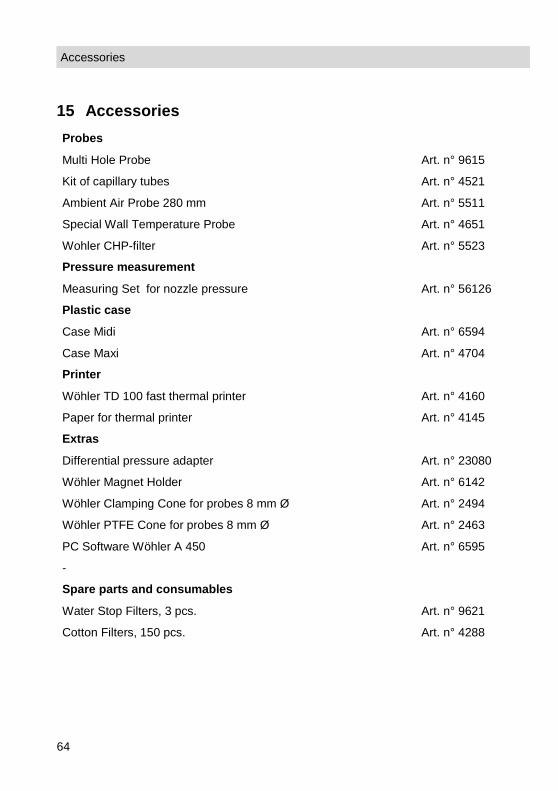
15 Accessories Probes
Multi Hole Probe Art. n° 9615
Kit of capillary tubes Art. n° 4521
Ambient Air Probe 280 mm Art. n° 5511
Special Wall Temperature Probe Art. n° 4651
Wohler CHP-filter Art. n° 5523
Pressure measurement
Measuring Set for nozzle pressure Art. n° 56126
Plastic case
Case Midi Art. n° 6594
Case Maxi Art. n° 4704
Printer
Wöhler TD 100 fast thermal printer Art. n° 4160
Paper for thermal printer Art. n° 4145
Extras
Differential pressure adapter Art. n° 23080
Wöhler Magnet Holder Art. n° 6142
Wöhler Clamping Cone for probes 8 mm Ø Art. n° 2494
Wöhler PTFE Cone for probes 8 mm Ø Art. n° 2463
PC Software Wöhler A 450 Art. n° 6595
-
Spare parts and consumables
Water Stop Filters, 3 pcs. Art. n° 9621
Cotton Filters, 150 pcs. Art. n° 4288
Accessories
65
Points of sale and service Germany Wöhler Technik GmbH Wöhler-Platz 1 33181 Bad Wünnenberg Tel.: +49 2953 73-100 Fax: +49 2953 73-96100 [email protected] www.woehler.de
Wöhler West Castroper Str. 105 44791 Bochum Tel.: +49 234 516993-0 Fax: +49 234 516993-99 [email protected]
Wöhler Süd Gneisenaustr.12 80992 München Tel.: +49 89 1589223-0 Fax: +49 89 1589223-99 [email protected]
USA Wohler USA Inc. 5 Hutchinson Drive Danvers, MA 01923 Tel.: +1 978 750 9876 Fax.: +1 978 750 9799 www.wohlerusa.com Italy Wöhler Italia srl Via Coraine 21 37010 Costermano VR Tel. +39 045 6200080 Fax. +39 045 6201508 [email protected] www.woehler.it Austria Wöhler GmbH Heinrich-Schneidmadl-Str. 15 3100 St. Pölten Tel.: +43 2742 90855-11 Fax: +43 2742 90855-22 [email protected]
Czech Republic Wöhler Bohemia s.r.o. Za Naspern 1993 393 01 Pelhrimov Tel.: +420 565 323 076 Fax: +420 565 323 078 [email protected] France Wöhler France SARL 31 Bis Rue Georges Ohnet 31200 Toulouse Tel.: +33 5 61 52 40 39 Fax: +33 5 62 27 11 31 [email protected] www.woehler.fr
Your contact: