WM2019 Conference, Phoenix, Arizona, USA
15
WM2019 Conference, Phoenix, Arizona, USA
Transcript of WM2019 Conference, Phoenix, Arizona, USA
WM2019 Conference, Phoenix, Arizona, USA
WM2019 Conference, Phoenix, Arizona, USA
Optimization of Backfill Material Transport for the Future Belgian Geological Disposal Facility H.-J. Engelhardt1, B. Haverkamp1, D. Raymaekers2
BGE TECHNOLOGY GmbH, Germany
ONDRAF/NIRAS, Belgium
ABSTRACT
Backfilling of underground excavations during or after operation of geological disposal facilities is part of most disposal concepts. The general conditions and requirements for this kind of operation vary signifi-cantly depending on the disposal concept and spatial dimensions of the underground layout. ONDRAF/NIRAS, the competent organization for radioactive waste management in Belgium, proposes a poorly indurated clay formation as host rock for the disposal of long-lived radioactive waste (working hypothesis). On the basis of the waste package number and properties a Geological Disposal Facility (GDF) was designed that should be located in a depth between 200 m and 600 m. Two shafts are foreseen in a central service area. Low- and intermediate-level waste (B waste) and high-level waste (C-waste) shall be disposed of each in one emplacement field. Two access galleries run through the middle of each field and connect the disposal galleries with the central service area and the shaft. The B waste field co-vers an area of 1.1 km² and the C waste field an area of 2.67 km². Both emplacement fields have a width of 0.90 km according to the length of the disposal galleries and the distance between the access galleries. The lengths are 1.20 km (B waste) and 2.73 km (C waste). After the emplacement of a specified number of waste packages, a stepwise backfilling of the voids is planned in order to stabilize the galleries and to ensure a favorable chemical milieu with regard to the overall disposal system including the waste packag-es, the sealing systems and the clay host rock. As part of a technology support framework contract BGE TECHNOLOGY GmbH developed backfilling materials and optimized transport concepts for the planned Belgian GDF. The reference materials are highly-flowable, cementitious mortars. The development of an optimized transport concept considered experiences from the German geological disposal facilities Konrad, Morsleben and Asse. Producers usually transport fine-grained materials, e.g. cement with silo trucks and sand with dumptrucks. Ordinary backfill systems for mines consist of storage facilities for the solid raw materials, the water and energy supply, the mix plant and a pumping station with the backfill pipeline. If possible, the mix plant and pumping station are installed above ground with a connection to public roads to allow easy delivery of the raw materials to the storage facilities. The backfill mixture is then pumped through the shaft and underground openings into the segments designated to be backfilled. This design has the advantage that installation of the plant in the restricted space underground is avoided, and dust and noise emissions un-derground are minimized. An essential prerequisite of this technical solution is a sufficiently long work-ing time and high flowability of the backfilling material. The backfilling system can be difficult to oper-ate, especially, when low amounts of the backfilling material are required or an extremely sensitive con-trolling of the flow rate and backfill amounts is necessary. In certain cases, the distance between the pump station and the backfill segment must be shortened. This can be achieved by transferring the mix and pumping units into the underground structures while the main storage facilities will remain above ground. Specific framework conditions, for example space re-strictions, the possibility of site access or the backfill composition, can require further modifications of the backfill system and the use of additional technical installations, such as auxiliary pumps.
WM2019 Conference, Phoenix, Arizona, USA
In order to identify the optimum solution for the Belgian reference GDF design, the decision criteria and the advantages and disadvantages of existing and planned transport systems were evaluated. In addition, the backfill system development considered the properties of the fresh reference backfill material. As failures of the backfill system would result in interruptions of waste package emplacement, a redundant pump and pipeline system was developed. The two lines can be operated separately or simultaneously in order to realize high flow rates in the course of backfilling segments far from the shaft. The evaluations and the finally preferred logistic solution will be presented.
Presentation Summary
Optimization of Backfill Material Transport for the Future Belgian Geological Disposal Facility Backfilling of underground excavations with self-curing, high-flowable materials is part of most disposal concepts. This approach requires the operation of a conveying system comprising a mix and pump station and pipelines. In the case of externally supplied raw materials, it is preferred to install the mix and pump station above ground. However, the rheological properties of the backfill, the disposal concept, and the GDF dimensions can result in changes of the backfill system. The evaluations and the finally pre-ferred solution for the Future Belgian GDF will be presented. Backfilling of underground excavations with bulk materials or self-curing, high-flowable suspensions is part of most disposal concepts. The use of flowable backfill requires the operation of a conveying system comprising as essential components a mix plant and a pumping station with the backfill pipeline. In the case of externally supplied raw materials, it is preferred to install the mix plant and pumping station above ground. However, the flow properties and the processing time of the backfill, the disposal concept, and the GDF dimensions can result in significant changes of the backfill system. The evaluations and the finally preferred technical solution for the Future Belgian Geological Disposal Facility will be presented.
WM2019 Conference, Phoenix, Arizona, USA
Optimization of Backfill Material Transport
for the Future Belgian Geological Disposal Facility – 19071 Hans-Joachim Engelhardt *, Bernt Haverkamp *, Didier Raymaekers ** * BGE TECHNOLOGY GmbH, Eschenstraße 55, D-31224 Peine, Germany
** ONDRAF/NIRAS, Avenue des Arts, 1210 Brussels, Belgium ABSTRACT In Belgium, long-lived, low- and intermediate level waste (B waste) will be conditioned in concrete monoliths B and high-level waste (C waste) in so-called Supercontainers (SC). It is planned to dispose of the waste packages in a Geological Disposal Facility (GDF). The B and C waste shall be disposed of each in one emplacement field in a depth between 200 m and 600 m below the surface. Two access galleries run through each field and connect the disposal galleries with a central shaft and support zone. After the emplacement of a specified number of waste packages, a stepwise backfilling of the voids is planned in order to stabilize the galleries, to limit the amount of voids, and to ensure a favourable chemical milieu. Taking into account the objectives of backfilling and the specific material properties of the waste packages two mortars were developed to backfill the disposal galleries. In particular, for reasons of safety at work, the mortars should be hydraulically pumped through pipelines. Accordingly, in any case, it is necessary to operate storage facilities of the raw materials, a mix plant and a pump. The raw materials are foreseen to be supplied by trucks from external producers. Due to this fact, the better accessibility of the plants and with the aim of minimizing noise and dust emissions and the space for technical systems in the GDF, it is advisable to install the technical equipment above ground outside the GDF control area. However, the feasibility of this basic concept depends on the processing time of the backfill materials and the capacity of the transport system. Thus, although short transport times can theoretically be realized if pipelines with a small cross sections are chosen, in this case the required power of the pump increases significantly. If no suitable configuration can be found, the distance of the mixing and pumping system to the backfill segment has to be shortened. In this case a pneumatic conveyor system would have to be installed to transport the solids to a mix plant and pumping unit located in the underground galleries to be able to meet the desired backfill rates. In order to identify the optimum solution, the decision criteria and the advantages and disadvantages of existing and planned transport systems were evaluated. The investigations showed that it is technically feasible to pump the backfill material from above ground into the disposal galleries. As failures of the backfill system would result in interruptions of the general disposal operation, a redundant pump and pipeline system was developed. The two lines can be operated separately or simultaneously in order to realize high flow rates needed for the backfilling of segments far from the shaft. INTRODUCTION In Belgium, the conditioned radioactive waste types are subdivided into three categories: A, B and C, based on their activity and the half-life of the radionuclides. Short-lived, low and intermediate level waste (A waste) presents a risk for man and the environment on a timescale of hundreds of years. The Belgian government decided in favour of a near surface disposal facility for this waste type. The risk that long-lived, low- and intermediate level waste (B waste) and high-level waste (C waste) present extends hundreds of millennia. Laboratory investigations and the experiments in the High Activity Disposal Experimental Site (HADES) demonstrate that the disposal of these waste types in a poorly indurated clay formation can be a safe and feasible solution. Consequently, ONDRAF/NIRAS, the Belgian National Agency for Radioactive Waste and enriched Fissile Material, proposes this host rock for the construction of a GDF (working hypothesis).
WM2019 Conference, Phoenix, Arizona, USA
Long-lived, low- and intermediate level waste (B waste) will be conditioned in concrete monoliths B and high-level waste (C waste) in so-called Supercontainers (SC). The SCs consist of a steel overpack embedded in a concrete buffer, and an outer stainless steel envelope. It is planned that the facility for disposal waste package (DWP) production and an interim storage facility will be erected at the surface near to the waste transport shaft. After the emplacement of a specified number of waste packages inside the underground disposal galleries, a stepwise backfilling of the voids is planned in order to stabilize the galleries, to limit the amount of voids, and to ensure a favourable chemical milieu. Considering the general objectives of backfilling, the properties of the DWPs and their long-term behaviour two reference materials were developed [1,2]. They are highly-flowable cement-based mortars. The final strength is relatively low in order to ensure the possibility of DWP retrieval. For reasons of safety at work, the mortars should be pumped through pipelines into the backfill segments. It is obvious that this procedure requires a mix plant and a pump. There are, however, numerous possibilities to position these essential components of the transport system. Due to a number of arguments it was favored to install the technical equipment above ground outside the GDF control area: the raw materials are supplied from external producers, the plants have a better accessibility, underground noise and dust emissions are minimized and the space for technical systems in the GDF is very restricted. The feasibility of this solution, however, depends on numerous influencing variables, such as the length and dimensioning of the delivery lines and thus the GDF design, the time dependent flowability of the backfill material. In order to identify the optimum solution for the Belgian reference GDF design, the feasibility of such a transport system was examined. In addition, alternatives for this concept of a hydraulic transport system were evaluated, considering existing backfill concepts and the experiences made. The decision criteria and the advantages and disadvantages of the different transport systems are described (cf. [3]). THE DESIGN OF THE GEOLOGICAL DISPOSAL FACILITY It is supposed that standardized and quality assured raw solid materials supplied by external producers have to be mixed with potable water for the production of the backfill. To backfill underground galleries, materials have to be transported from an above ground storage site through a shaft into the underground galleries, regardless of whether raw materials or backfill mixtures are being transported. The design of the GDF, which is still a hypothetical design, defines the distances to be covered during transport. It has a special significance for the design of the backfill or transport system. According to common practice, in the preliminary design the surface area is divided into an inner and an outer perimeter. Peripheral roads will be built along the inner and outer fence for site traffic and to facili-tate security patrolling. For visitors a reception and communication center is accessible. However, in or-der to get into the area of the outer perimeter, an adjacent guardhouse has to be passed, where people and vehicle controls take place. By analogy, checks are made when passing the inside perimeter. It is this inner part of the site, where the post-conditioning buildings of the B and C waste packages and the shafts with the shaft buildings are located. These facilities and the connecting roads in a central area are sur-rounded by dumps consisting of the rock materials, which were excavated during the construction of the shafts and underground structures. The outer perimeter forms a rectangle with side lengths of 0.92 km and 1.16 km and thus an area of 1.08 km². Two shafts connect the surface and underground structures. One shaft serves the transport of waste packages. The second one, called personnel or access shaft, is designed for staff and material transport. In this shaft pipelines for material transports can be installed. The study considered reference shaft depths of 200 m, 400 m, and 600 m.
WM2019 Conference, Phoenix, Arizona, USA
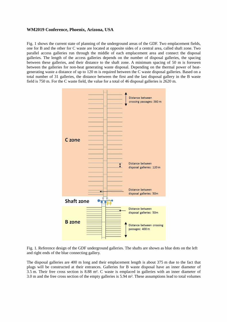
Fig. 1 shows the current state of planning of the underground areas of the GDF. Two emplacement fields, one for B and the other for C waste are located at opposite sides of a central area, called shaft zone. Two parallel access galleries run through the middle of each emplacement area and connect the disposal galleries. The length of the access galleries depends on the number of disposal galleries, the spacing between these galleries, and their distance to the shaft zone. A minimum spacing of 50 m is foreseen between the galleries for non-heat generating waste disposal. Depending on the thermal power of heat-generating waste a distance of up to 120 m is required between the C waste disposal galleries. Based on a total number of 31 galleries, the distance between the first and the last disposal gallery in the B waste field is 750 m. For the C waste field, the value for a total of 46 disposal galleries is 2620 m.
Fig. 1. Reference design of the GDF underground galleries. The shafts are shown as blue dots on the left and right ends of the blue connecting gallery. The disposal galleries are 400 m long and their emplacement length is about 375 m due to the fact that plugs will be constructed at their entrances. Galleries for B waste disposal have an inner diameter of 3.5 m. Their free cross section is 8.88 m². C waste is emplaced in galleries with an inner diameter of 3.0 m and the free cross section of the empty galleries is 5.94 m². These assumptions lead to total volumes
WM2019 Conference, Phoenix, Arizona, USA
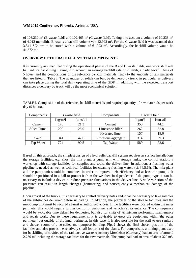
of 103,230 m³ (B waste field) and 102,465 m³ (C waste field). Taking into account a volume of 60,238 m³ of 4,012 monoliths B results a backfill volume von 42,992 m³. For the C waste field it was assumed that 3,341 SCs are to be stored with a volume of 61,093 m³. Accordingly, the backfill volume would be 41,372 m³. OVERVIEW OF THE BACKFILL SYSTEM COMPONENTS It is currently assumed that during the operational phases of the B and C waste fields, one work shift will be used for backfilling. Taking into account an average backfill rate of 25 m³/h, a daily backfill time of 5 hours, and the compositions of the reference backfill materials, leads to the amounts of raw materials that are listed in Table I. The quantities of solids can best be delivered by truck, in particular as delivery can take place during the total daily operating time of the GDF. In addition, with the expected transport distances a delivery by truck will be the most economical solution. TABLE I. Composition of the reference backfill materials and required quantity of raw materials per work day (5 hours).
Components B waste field Components C waste field [kg/m³] [tons/d] [kg/m³] [tons/d]
Cement 170 21.3 Cement 353 44.1 Silica Fume 200 25.0 Limestone filler 262 32.8
Hydrated lime 157 19.6 Sand 341 42.6 Limestone aggregate 314 39.3
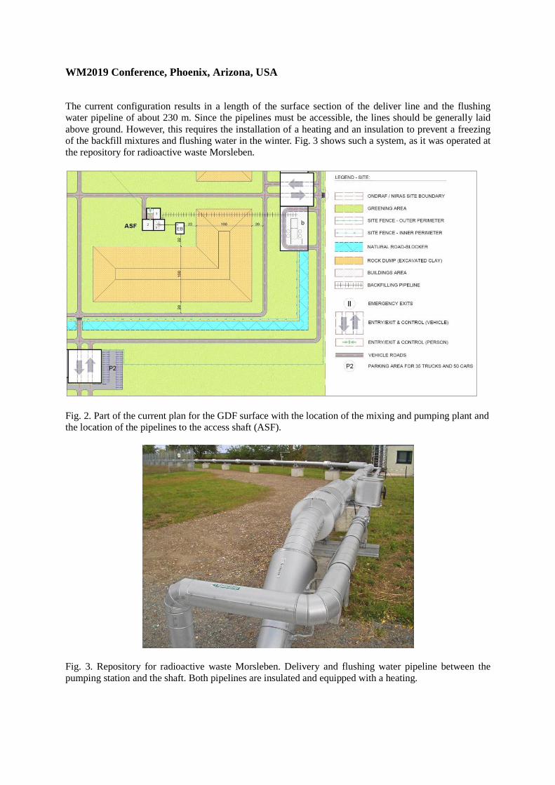
Tap Water 724 90.5 Tap Water 589 73.6 Based on this approach, the simplest design of a hydraulic backfill system requires as surface installations the storage facilities, e.g. silos, the mix plant, a pump unit with storage tanks, the control station, a workshop with storage facilities for supplies and tools, the deliver line. In addition, a flushing water pipeline is needed as well as technical facilities for cleaning flushing waters (cf. [4,5,6]). The mix plant and the pump unit should be combined in order to improve their efficiency and at least the pump unit should be positioned in a hall to protect it from the weather. In dependence of the pump type, it can be necessary to include a device to reduce pressure fluctuations in the deliver line. A wide variation of the pressures can result in length changes (hammering) and consequently a mechanical damage of the pipeline. Upon arrival of the trucks, it is necessary to control delivery notes and it can be necessary to take samples of the substances delivered before unloading. In addition, the premises of the storage facilities and the mix-pump unit must be secured against unauthorized access. If the facilities were located within the inner perimeter this would require further control of personnel and vehicles at its entrance. The consequence would be avoidable time delays for deliveries, but also for visits of technicians performing maintenance and repair work. Due to these requirements, it is advisable to erect the equipment within the outer perimeter, but outside of the inner perimeter. In this case, it is also possible for the staff to use sanitary and shower rooms of a so-called multipurpose building. Fig. 2 shows the final chosen position of the facilities and also proves the relatively small footprint of the plants. For comparison, a mixing plant used for backfilling of cavities of the radioactive waste repository Morsleben (Germany) had an area of around 2,280 m² including the storage facilities for the raw materials. The pump hall had an area of about 320 m².
WM2019 Conference, Phoenix, Arizona, USA
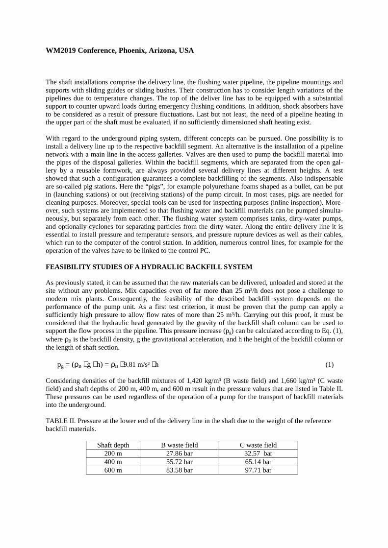
The current configuration results in a length of the surface section of the deliver line and the flushing water pipeline of about 230 m. Since the pipelines must be accessible, the lines should be generally laid above ground. However, this requires the installation of a heating and an insulation to prevent a freezing of the backfill mixtures and flushing water in the winter. Fig. 3 shows such a system, as it was operated at the repository for radioactive waste Morsleben.
Fig. 2. Part of the current plan for the GDF surface with the location of the mixing and pumping plant and the location of the pipelines to the access shaft (ASF).
Fig. 3. Repository for radioactive waste Morsleben. Delivery and flushing water pipeline between the pumping station and the shaft. Both pipelines are insulated and equipped with a heating.
WM2019 Conference, Phoenix, Arizona, USA
The shaft installations comprise the delivery line, the flushing water pipeline, the pipeline mountings and supports with sliding guides or sliding bushes. Their construction has to consider length variations of the pipelines due to temperature changes. The top of the deliver line has to be equipped with a substantial support to counter upward loads during emergency flushing conditions. In addition, shock absorbers have to be considered as a result of pressure fluctuations. Last but not least, the need of a pipeline heating in the upper part of the shaft must be evaluated, if no sufficiently dimensioned shaft heating exist. With regard to the underground piping system, different concepts can be pursued. One possibility is to install a delivery line up to the respective backfill segment. An alternative is the installation of a pipeline network with a main line in the access galleries. Valves are then used to pump the backfill material into the pipes of the disposal galleries. Within the backfill segments, which are separated from the open gal-lery by a reusable formwork, are always provided several delivery lines at different heights. A test showed that such a configuration guarantees a complete backfilling of the segments. Also indispensable are so-called pig stations. Here the “pigs”, for example polyurethane foams shaped as a bullet, can be put in (launching stations) or out (receiving stations) of the pump circuit. In most cases, pigs are needed for cleaning purposes. Moreover, special tools can be used for inspecting purposes (inline inspection). More-over, such systems are implemented so that flushing water and backfill materials can be pumped simulta-neously, but separately from each other. The flushing water system comprises tanks, dirty-water pumps, and optionally cyclones for separating particles from the dirty water. Along the entire delivery line it is essential to install pressure and temperature sensors, and pressure rupture devices as well as their cables, which run to the computer of the control station. In addition, numerous control lines, for example for the operation of the valves have to be linked to the control PC. FEASIBILITY STUDIES OF A HYDRAULIC BACKFILL SYSTEM As previously stated, it can be assumed that the raw materials can be delivered, unloaded and stored at the site without any problems. Mix capacities even of far more than 25 m³/h does not pose a challenge to modern mix plants. Consequently, the feasibility of the described backfill system depends on the performance of the pump unit. As a first test criterion, it must be proven that the pump can apply a sufficiently high pressure to allow flow rates of more than 25 m³/h. Carrying out this proof, it must be considered that the hydraulic head generated by the gravity of the backfill shaft column can be used to support the flow process in the pipeline. This pressure increase (pg) can be calculated according to Eq. (1), where ρB is the backfill density, g the gravitational acceleration, and h the height of the backfill column or the length of shaft section.
pg = (ρB ⋅ g ⋅ h) = ρB ⋅ 9.81 m/s² ⋅ h (1)
Considering densities of the backfill mixtures of 1,420 kg/m³ (B waste field) and 1,660 kg/m³ (C waste field) and shaft depths of 200 m, 400 m, and 600 m result in the pressure values that are listed in Table II. These pressures can be used regardless of the operation of a pump for the transport of backfill materials into the underground. TABLE II. Pressure at the lower end of the delivery line in the shaft due to the weight of the reference backfill materials.
Shaft depth B waste field C waste field 200 m 27.86 bar 32.57 bar 400 m 55.72 bar 65.14 bar 600 m 83.58 bar 97.71 bar
WM2019 Conference, Phoenix, Arizona, USA
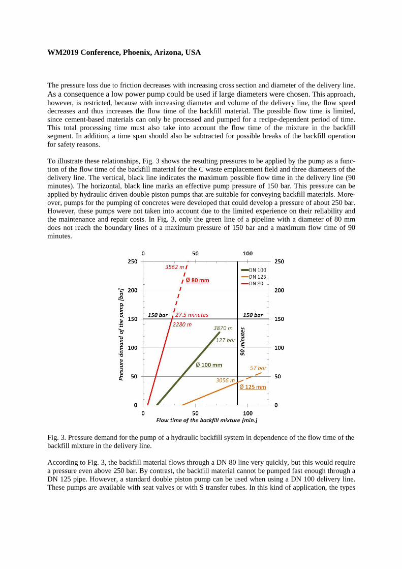
The pressure loss due to friction decreases with increasing cross section and diameter of the delivery line. As a consequence a low power pump could be used if large diameters were chosen. This approach, however, is restricted, because with increasing diameter and volume of the delivery line, the flow speed decreases and thus increases the flow time of the backfill material. The possible flow time is limited, since cement-based materials can only be processed and pumped for a recipe-dependent period of time. This total processing time must also take into account the flow time of the mixture in the backfill segment. In addition, a time span should also be subtracted for possible breaks of the backfill operation for safety reasons. To illustrate these relationships, Fig. 3 shows the resulting pressures to be applied by the pump as a func-tion of the flow time of the backfill material for the C waste emplacement field and three diameters of the delivery line. The vertical, black line indicates the maximum possible flow time in the delivery line (90 minutes). The horizontal, black line marks an effective pump pressure of 150 bar. This pressure can be applied by hydraulic driven double piston pumps that are suitable for conveying backfill materials. More-over, pumps for the pumping of concretes were developed that could develop a pressure of about 250 bar. However, these pumps were not taken into account due to the limited experience on their reliability and the maintenance and repair costs. In Fig. 3, only the green line of a pipeline with a diameter of 80 mm does not reach the boundary lines of a maximum pressure of 150 bar and a maximum flow time of 90 minutes.
Fig. 3. Pressure demand for the pump of a hydraulic backfill system in dependence of the flow time of the backfill mixture in the delivery line. According to Fig. 3, the backfill material flows through a DN 80 line very quickly, but this would require a pressure even above 250 bar. By contrast, the backfill material cannot be pumped fast enough through a DN 125 pipe. However, a standard double piston pump can be used when using a DN 100 delivery line. These pumps are available with seat valves or with S transfer tubes. In this kind of application, the types
WM2019 Conference, Phoenix, Arizona, USA
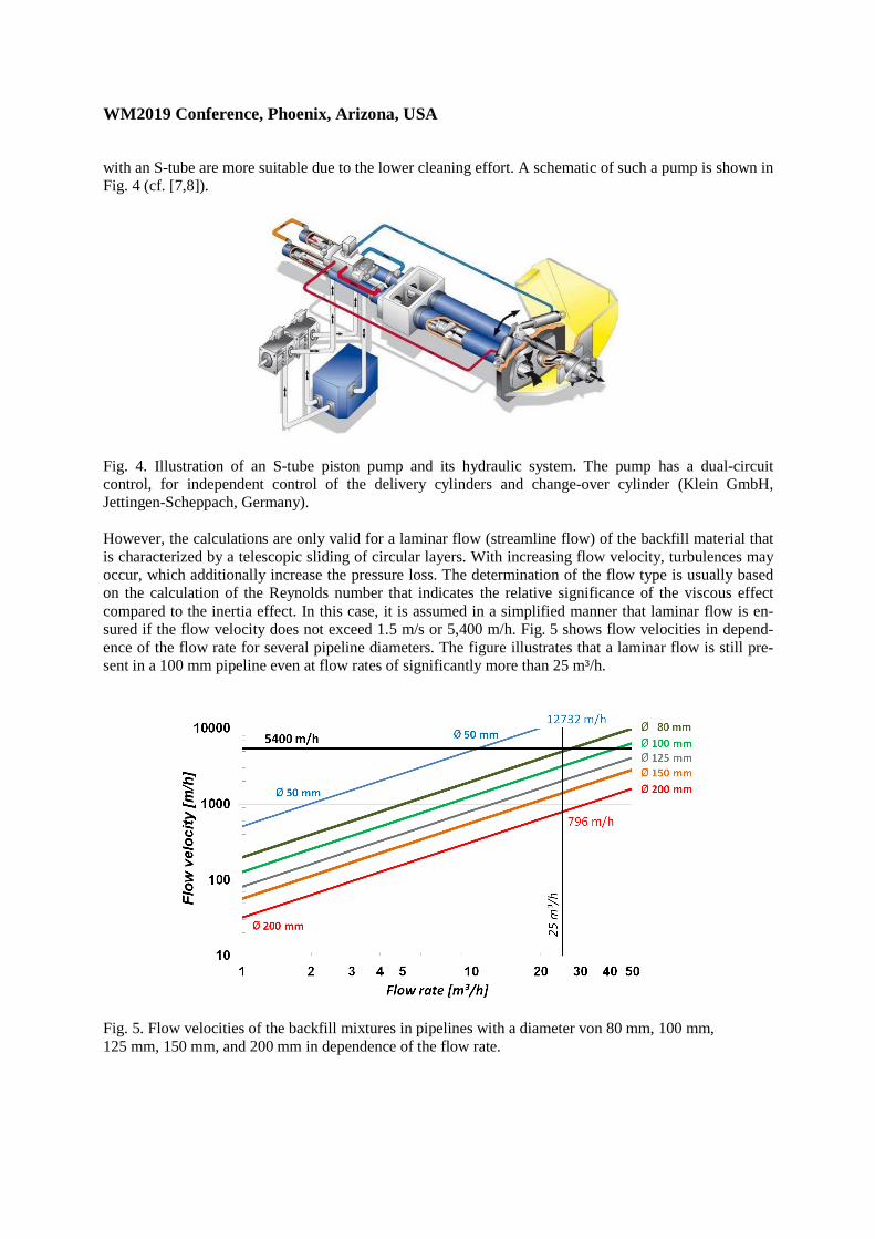
with an S-tube are more suitable due to the lower cleaning effort. A schematic of such a pump is shown in Fig. 4 (cf. [7,8]).
Fig. 4. Illustration of an S-tube piston pump and its hydraulic system. The pump has a dual-circuit control, for independent control of the delivery cylinders and change-over cylinder (Klein GmbH, Jettingen-Scheppach, Germany). However, the calculations are only valid for a laminar flow (streamline flow) of the backfill material that is characterized by a telescopic sliding of circular layers. With increasing flow velocity, turbulences may occur, which additionally increase the pressure loss. The determination of the flow type is usually based on the calculation of the Reynolds number that indicates the relative significance of the viscous effect compared to the inertia effect. In this case, it is assumed in a simplified manner that laminar flow is en-sured if the flow velocity does not exceed 1.5 m/s or 5,400 m/h. Fig. 5 shows flow velocities in depend-ence of the flow rate for several pipeline diameters. The figure illustrates that a laminar flow is still pre-sent in a 100 mm pipeline even at flow rates of significantly more than 25 m³/h.
Fig. 5. Flow velocities of the backfill mixtures in pipelines with a diameter von 80 mm, 100 mm, 125 mm, 150 mm, and 200 mm in dependence of the flow rate.
WM2019 Conference, Phoenix, Arizona, USA
A greater depth of the shaft is no problem for the backfill operation because the pressure gain by the weight of the backfill material is greater than the pressure loss during the conveying process. In addition, the flow time increases only slightly. It is about 80 minutes when assuming a DN 100 pipeline and a shaft depth of 600 m. The calculations show that the disposal galleries can be filled with a hydraulic conveyor and common technical equipment. This also applies to the B waste field, because the pipelines are signifi-cantly shorter and thus the pressure losses during the pump process significantly lower. In addition, the flow times of the backfill material are shorter. It is envisaged to backfill the disposal galleries only during one shift. This approach results in a relatively high cleaning effort of the conveyor system. Flushing water tanks and dirty water pumps must be set up in the underground structures. FIG. 1 shows that two parallel access galleries run through the emplacement fields. They are connected by crossing passages. This design allows an installation of a pipeline loop, by connecting the main delivery lines in the access galleries through the crossing passages. The loop starts and ends at the pump unit. Due to the uniform cross section of the loop, pigs and cleaning sponges can be conveyed through the entire pipeline. A positive secondary effect of this solution is that the backfill material can be pumped in both directions. Pipeline blockages can be more easily removed, because a pressure can be applied against the original flow direction. If a second pump is installed, a flexibly usable redundant system exists that allows adjustments to the needs of backfilling. EVALUATION OF ALTERNATIVE BACKFILL SYSTEMS Alternative methods for the transport of the ready-mixed backfill into the underground structures does not make sense, because they take a longer time and require higher personnel efforts. In addition, so-called discontinuous transport systems, e.g. with tanks or vessels require frequent trips with the hoisting system and should be avoided in order to minimize transport activities. The hoisting system should preferably be available for trips of the staff. The use of tanks or vessels would also require a large amount of space for storage and transportation near the shaft, both above ground and in the shaft zone. It should also be noted the large logistical effort, as the shaft would be the only channel for the transport of products, e.g. tech-nical equipment, staff, and all kinds of material. These transports could not be carried out independently of each other. However, an alternative that is frequently used is the transport of the raw materials through shaft pipelines and the mixing of backfill materials in the underground. In order to define the optimum concept for the Belgian situation, the advantages and disadvantages of the different concepts were proper-ly balanced. A disadvantage of underground mixing is that a transport system of the raw materials is required in the shaft and intermediate storage capacities have to be set up underground. In comparison to a mixing of the backfill material at the surface, it is also worth mentioning that higher personnel expenses are to be expected in the underground structures, also from external technicians who carry out maintenance and repair work. Higher noise and dust emissions should be considered with regard to workers health and safety as well as an increased use of fuels, oils, consumables, and especially of hazardous substances. Regarding the raw materials a discontinuous transport of bags, silos, etc. is inefficient in analogy to the transport of the mixed backfill material. Fine-grained products can be transported by pneumatic conveying systems into the underground galleries, whereby it is often advantageous to transport premixes of the solids. In the case of reference backfill materials, this approach could be implemented. Pneumatic conveying systems require an installation of a receiver station and storage facilities. The GDF design initially suggests to install these facilities in the shaft zone of the GDF and to operate there the mix plant. In this case, three concepts can be distinguished with respect to the transport of the mixtures. 1) A pump transports the backfill material through a pipeline distribution system into the backfill
segments (hydraulic backfill system).
WM2019 Conference, Phoenix, Arizona, USA
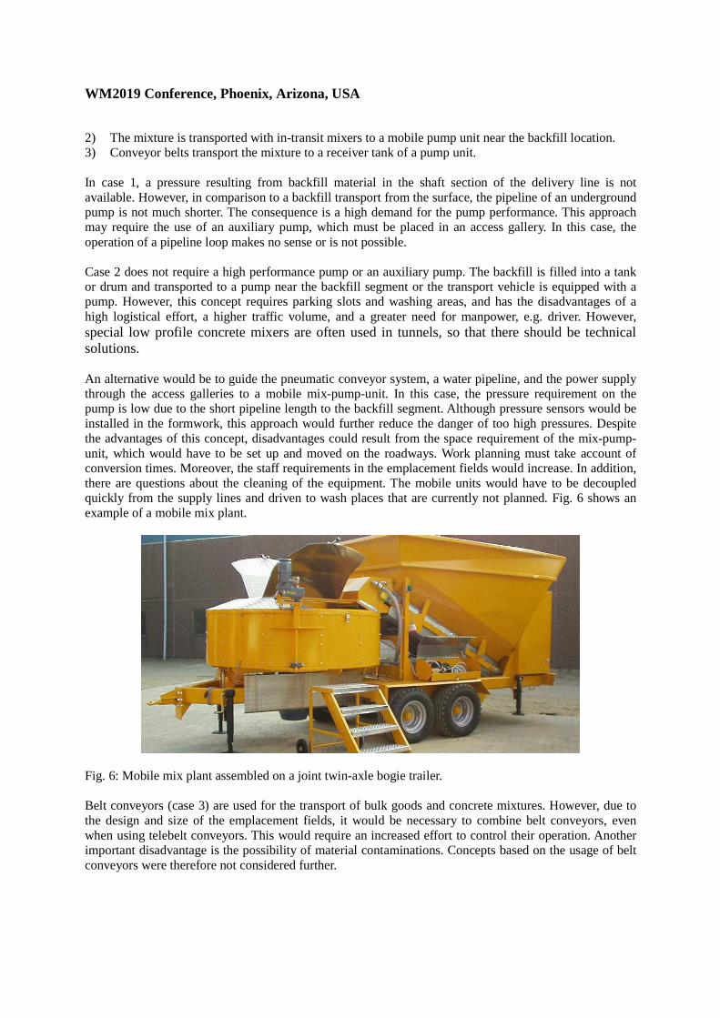
2) The mixture is transported with in-transit mixers to a mobile pump unit near the backfill location. 3) Conveyor belts transport the mixture to a receiver tank of a pump unit. In case 1, a pressure resulting from backfill material in the shaft section of the delivery line is not available. However, in comparison to a backfill transport from the surface, the pipeline of an underground pump is not much shorter. The consequence is a high demand for the pump performance. This approach may require the use of an auxiliary pump, which must be placed in an access gallery. In this case, the operation of a pipeline loop makes no sense or is not possible. Case 2 does not require a high performance pump or an auxiliary pump. The backfill is filled into a tank or drum and transported to a pump near the backfill segment or the transport vehicle is equipped with a pump. However, this concept requires parking slots and washing areas, and has the disadvantages of a high logistical effort, a higher traffic volume, and a greater need for manpower, e.g. driver. However, special low profile concrete mixers are often used in tunnels, so that there should be technical solutions. An alternative would be to guide the pneumatic conveyor system, a water pipeline, and the power supply through the access galleries to a mobile mix-pump-unit. In this case, the pressure requirement on the pump is low due to the short pipeline length to the backfill segment. Although pressure sensors would be installed in the formwork, this approach would further reduce the danger of too high pressures. Despite the advantages of this concept, disadvantages could result from the space requirement of the mix-pump-unit, which would have to be set up and moved on the roadways. Work planning must take account of conversion times. Moreover, the staff requirements in the emplacement fields would increase. In addition, there are questions about the cleaning of the equipment. The mobile units would have to be decoupled quickly from the supply lines and driven to wash places that are currently not planned. Fig. 6 shows an example of a mobile mix plant.
Fig. 6: Mobile mix plant assembled on a joint twin-axle bogie trailer. Belt conveyors (case 3) are used for the transport of bulk goods and concrete mixtures. However, due to the design and size of the emplacement fields, it would be necessary to combine belt conveyors, even when using telebelt conveyors. This would require an increased effort to control their operation. Another important disadvantage is the possibility of material contaminations. Concepts based on the usage of belt conveyors were therefore not considered further.
WM2019 Conference, Phoenix, Arizona, USA
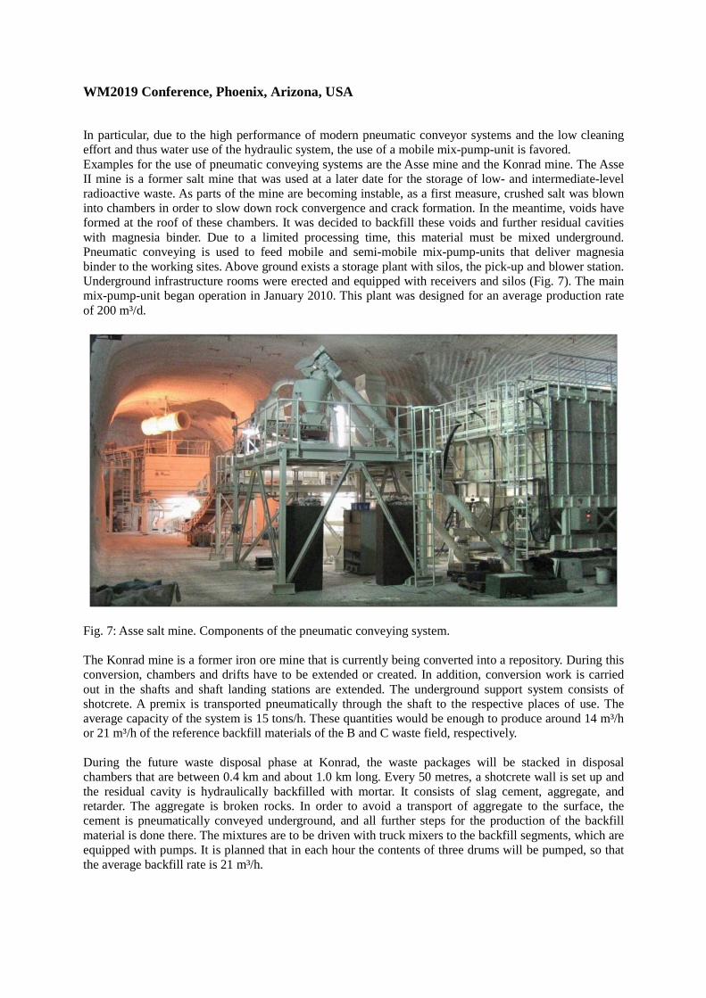
In particular, due to the high performance of modern pneumatic conveyor systems and the low cleaning effort and thus water use of the hydraulic system, the use of a mobile mix-pump-unit is favored. Examples for the use of pneumatic conveying systems are the Asse mine and the Konrad mine. The Asse II mine is a former salt mine that was used at a later date for the storage of low- and intermediate-level radioactive waste. As parts of the mine are becoming instable, as a first measure, crushed salt was blown into chambers in order to slow down rock convergence and crack formation. In the meantime, voids have formed at the roof of these chambers. It was decided to backfill these voids and further residual cavities with magnesia binder. Due to a limited processing time, this material must be mixed underground. Pneumatic conveying is used to feed mobile and semi-mobile mix-pump-units that deliver magnesia binder to the working sites. Above ground exists a storage plant with silos, the pick-up and blower station. Underground infrastructure rooms were erected and equipped with receivers and silos (Fig. 7). The main mix-pump-unit began operation in January 2010. This plant was designed for an average production rate of 200 m³/d.
Fig. 7: Asse salt mine. Components of the pneumatic conveying system. The Konrad mine is a former iron ore mine that is currently being converted into a repository. During this conversion, chambers and drifts have to be extended or created. In addition, conversion work is carried out in the shafts and shaft landing stations are extended. The underground support system consists of shotcrete. A premix is transported pneumatically through the shaft to the respective places of use. The average capacity of the system is 15 tons/h. These quantities would be enough to produce around 14 m³/h or 21 m³/h of the reference backfill materials of the B and C waste field, respectively. During the future waste disposal phase at Konrad, the waste packages will be stacked in disposal chambers that are between 0.4 km and about 1.0 km long. Every 50 metres, a shotcrete wall is set up and the residual cavity is hydraulically backfilled with mortar. It consists of slag cement, aggregate, and retarder. The aggregate is broken rocks. In order to avoid a transport of aggregate to the surface, the cement is pneumatically conveyed underground, and all further steps for the production of the backfill material is done there. The mixtures are to be driven with truck mixers to the backfill segments, which are equipped with pumps. It is planned that in each hour the contents of three drums will be pumped, so that the average backfill rate is 21 m³/h.
WM2019 Conference, Phoenix, Arizona, USA
CONCLUSIONS According to the current Belgian reference concept, the disposal galleries of the Belgian GDF shall be backfilled with cement-based mortars. All raw materials of the mortars are delivered to the GDF, so that the mixing of the backfill materials must be done on site. With regard to the operation of the GDF, im-portant principles are to minimize the operating staff in the underground areas and to ensure favourable working conditions for the staff. So dust and noise emissions should be avoided. In addition, the required underground travel should be limited and the use of water, such as cleaning water of technical equipment and vehicles. These requirements and the possibilities offered by the dimension and design of the GDF led to the preference for mixing the backfill at the surface and to pump the mixtures through a pipeline system. Investigations, taking into account the flow properties and the processing time of the reference backfill materials and the GDF design showed that such systems can be operated and is sufficiently pow-erful (cf. [9]). Developments of technical equipment are not required. Due to the fact that available and proven technical facilities can be used, a detailed planning of the transport system could already be car-ried out. Thus, the locations of the individual technical facilities at the future GDF site have been deter-mined. As failures of the backfill system would result in interruptions of the whole disposal operation, a redundant pump and pipeline system was developed that uses a pipeline loop. The two lines can be operated separately or simultaneously in order to realize high flow rates. In addition, to the development of the preferred solution also alternatives were investigated. The investigations showed that it is most efficient to pneumatically convey the raw materials underground and to operate a mobile mix-pump-unit close to the backfill segments. REFERENCES 1. H.-J. Engelhardt, B. Haverkamp, L.E. von Borstel, P. van Marcke and E. Coppens, Development of a
Reference Backfill Material for the Disposal Galleries in the current Belgian Reference Concept for the Geological Disposal of Long-lived and High-level Waste. WM2015-Conference, March 15-19, 2015, Phoenix, Arizona, USA (2015).
2. H.-J. Engelhardt, B. Haverkamp and D. Raymaekers, Backfilling of Geological Disposal Facilities – Development of Optimized Backfill Material. WM2018-Conference, March 18-22, 2018, Phoenix, Arizona, USA (2018).
3. M.J. Scoble and L. Piciacchia, “Hydraulic backfill design to optimize support and cost effectiveness”. Mine Science and Technology, 4, 75 (1986)
4. J.S. Walker, State-of-the-Art Techniques for Backfilling Abandoned Mine Voids. United States Department of the Interior, Bureau of Mines (USBM) Information Circular 9359 (1993).
5. R. Cooke, “Design procedure for hydraulic backfill distribution systems. Journal of the South African Institute of Mining and Metallurgy, March/April 2001, 97 (2001).
6. R. Cooke, “Backfill pipeline distribution systems – design methodology review”. CIM Bulletin, 100, 1 (2007).
7. B. Nesbitt, “Pumping Manual International. Handbook of Pumps and Pumping”. Elsevier in association with Roles & Associates Ltd. (2006).
8. S. Jacobsen, J.H. Mork, S.F. Lee and L. Haugan, “Pumping of concrete and mortar – State of the art”. COIN Project report 5, SP 2.4 Workability, SINTEF Building and Infrastructure (2008).
9. K. d’Obyrn and W. Wiewiórka, “Selection of backfilling technology works of the Wieliczka salt mine”. AGH Journal of Mining and Geoengineering, 36, 107 (2012).
10. K.A. Riding, J. Vosahlik, D. Feys, T. Malone and W. Lindquist, “Best Practices for Concrete Pump-ing”. Kansas Department of Transportation, Report No. K-TRAN: KSU-14-2 (2016).