WKM DynaSeal 210 and 310 Floating Ball ValvesAccording to NACE MR0175/ISO 15156, it is the...
44
WKM DynaSeal 210 and 310 Floating Ball Valves Industry-recognized flanged and threaded end floating ball valves for oilfield and industrial applications
Transcript of WKM DynaSeal 210 and 310 Floating Ball ValvesAccording to NACE MR0175/ISO 15156, it is the...

WKM DynaSeal 210 and 310 Floating Ball Valves Industry-recognized flanged and threaded end floating ball valves for oilfield and industrial applications

WKM DynaSeal 210 anD 310 FloatIng Ball ValVeS
WKM DynaSeal 210 Floating Ball Valves
How to Order ................................................................................. 1
Features and Benefits ..................................................................... 2
Exploded View and Specifications ................................................... 4
Materials List .................................................................................. 5
Dimensions and Weights ................................................................ 6
WKM DynaSeal 310 Floating Ball Valves
Trim Guidelines for All DynaSeal 310 Valves .................................... 7
How to Order ................................................................................. 8
Features and Benefits ...................................................................... 9
Exploded Views and Specifications
•SocketWeldEnds ................................................................. 12
•ThreadedConnections .......................................................... 13
•FlangedConnections ............................................................ 14
Materials List – Threaded and Flanged Ends .................................... 15
Dimensional Data – 4” Reduced Port and Smaller
1/4” Full Port through 4” Reduced Port:
Flanged,ThreadedandSocketWeld ............................................... 16
Features and Benefits ...................................................................... 18
Exploded Views and Specifications .................................................. 21
Materials List .................................................................................. 23
Dimensional Data – 4” Full Port and larger
4” Full Port through 8” Reduced Port ............................................. 24
Pressure/Temperature for All DynaSeal 310 Valves ........................... 26
Weights .......................................................................................... 29
FlowCharacteristics ........................................................................ 30
Stem Torques .................................................................................. 31
WKM DynaSeal 210 and 310 Floating Ball Valves
Material Selection Guide ................................................................. 33
CAMSERVServicesforValvesandActuation ......................................... 40
TrademarkInformation ......................................................................... 41
table of Contents

1
WKM DynaSeal 210 Floating Ball Valves HoW to oRDeR
NACEMR0175/ISO15156Compliance–Materialsofconstructionshallbeincompliancewiththepre-qualifiedmaterialrequirementsspecifiedbyNACEMR0175/ISO15156.AccordingtoNACEMR0175/ISO15156,itisthemanufacturer’sresponsibilityformeetingmetallurgicalrequirementsandthecustomer/userresponsibilitytoensurethatamaterialwillbesatisfactoryintheintendedenvironment.Whengiventheapplicationrequirements(environment)bythecustomer/user,CameroncanmaketechnicalrecommendationsinaccordancewithNACEMR0175/ISO15156,butthatinnowaycertifiesorwarrants the product or materials for the application.
J0XXXXX - 2 1 X X X 0 X
Base Part Pressure Rating Body Seat Seal Ball and Handle
Number (CWP) Material Trim Material Stem
Buna 1
FKM 2
No Handle 0
Handle 1
No Handle with Seal Pin
2
Handle with Seal Pin
3CarbonSteel 1
Stainless Steel 2
CarbonSteelUnidirectional 3
StainlessSteelUnidirectional 4
DuctileIron 1
Size Basenumberin. (mm)
2x1-1/2 (50 x 40) 24925
2 x 2 (50 x 50) 25144
3 x 2 (80 x 50) 24926
3 x 3 (80 x 80) 25145
4 x 3 (100 x 80) 25154
Female threaded ends750/1000# MoP
1500/2000# MoP
1 x 1 (25 x 25) 24190
2x1-1/2 (50 x 40) 24132
2 x 2 (50 x 50) 24056
2-1/2x2 (65 x 50) 24059
3 x 2 (80 x 50) 24063
3 x 3 (80 x 80) 24178*
4 x 3 (100 x 80) 24211*
* Maximum pressure rating of 1500 psi for 4” x 3” (100 mm x 80 mm) and 3” x 3” (80 mm x 80 mm).
grooved ends 750# MoP
2x1-1/2 (50 x 40) 25111
3 x 2 (80 x 50) 25112
4 x 3 (100 x 80) 25113
Acetal Plastic (43) 3
Filled Teflon (42) 5
750 psi 1
1000 psi 2
1500 psi 3
2000 psi 4
Examples: StandardTrim2”(50mm) J024925-2131100
H2S,NACETrimSuffixCode =standard-213220X
=unidirectional-213240X
* See page 4 for details.
2
• Productionwingvalvesonlow-pressuregaswells
• Productionflowlines
• Productiongatheringsystemsforwater,oilandgas
• Gasblowdownservice
• Tankbatteriesforstorageorproduction
• Fracwatertanks
FeatuReS anD BeneFItS
open or closed positionlocking handle
This rugged yet economical ductile iron ball valve is ideal for threaded end oilfield applications where carbon steel body material is not a requirement.
Cameron’sWKM® DynaSeal™210ballvalveisatwo-piecedesignwithaductileironbodyandtailpiece.ThisvalveiseconomicalandincludesmanyofthepremiumdesignfeaturesfoundintheWKMDynaSeal310carbonsteelballvalve.
Itisavailablein1”to4”x3”(25mmto100mmx80mm)sizes.Workingpressuresofferedare750,1000,1500and2000psi.(Seesize/pressuretableonpage5.)
Thisvalveisusedprimarilyintheoilfieldmarketforthefollowingapplications:
Double o-ringstem seal
Handle providespositive indication ofopen/closed position
Stem gasketreduces torqueand provides asecondary stem seal
Positively retainedstem cannot beremoved withvalve in service
Recessed “deep pocket” seat is protected from flow
3
Locking Capability is Standard
• Thevalvecanbelockedintheopenor closed position.
Positively Retained Stem
• Thestemispositivelyretained.Itisdesignedtopreventstemblowoutwhile the valve is in service.
Color-coded Working Pressures
Thelockplatesarecolor-codedsopressureratingsarequicklyidentified.
• 750/1000 psi: green
• 1500psi:blue
• 2000psi:red
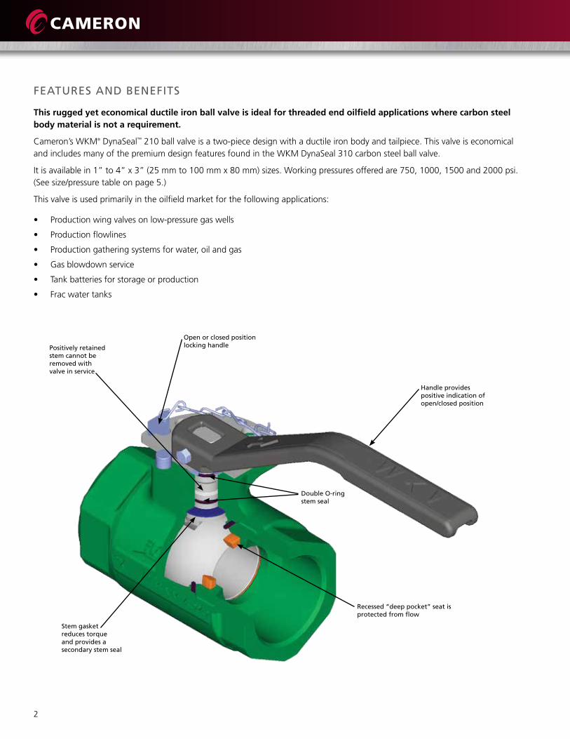
Unidirectional Ball (Option)
The WKM DynaSeal 210 unidirectional valve option provides relief to valves that might have water trapped in the bodycavityandthenareexposedtoatemporaryfreeze.Sincethisoptionreliesonareliefholeintheballtorelieve the excess pressure, the valve is stamped with a directional flow arrow tobesurethesideoftheballwiththehole is installed upstream.
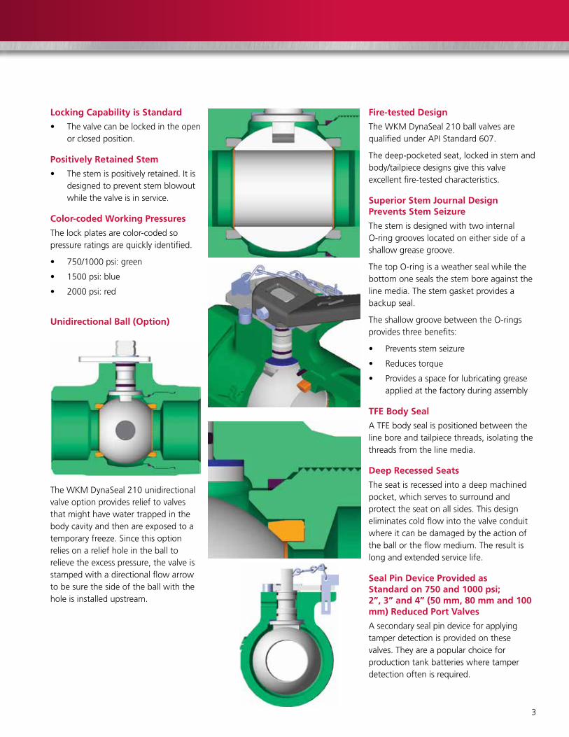
Fire-tested Design
TheWKMDynaSeal210ballvalvesarequalifiedunderAPIStandard607.
Thedeep-pocketedseat,lockedinstemandbody/tailpiecedesignsgivethisvalveexcellentfire-testedcharacteristics.
Superior Stem Journal Design Prevents Stem Seizure
The stem is designed with two internal O-ringgrooveslocatedoneithersideofashallow grease groove.
ThetopO-ringisaweathersealwhilethebottomonesealsthestemboreagainstthelinemedia.Thestemgasketprovidesabackupseal.
TheshallowgroovebetweentheO-ringsprovidesthreebenefits:
• Preventsstemseizure
• Reducestorque
• Providesaspaceforlubricatinggreaseapplied at the factory duringassembly
TFE Body Seal
ATFEbodysealispositionedbetweenthelineboreandtailpiecethreads,isolatingthethreads from the line media.
Deep Recessed Seats
The seat is recessed into a deep machined pocket,whichservestosurroundandprotect the seat on all sides. This design eliminates cold flow into the valve conduit whereitcanbedamagedbytheactionoftheballortheflowmedium.Theresultislong and extended service life.
Seal Pin Device Provided as Standard on 750 and 1000 psi; 2”, 3” and 4” (50 mm, 80 mm and 100 mm) Reduced Port Valves
A secondary seal pin device for applying tamper detection is provided on these valves. They are a popular choice for productiontankbatterieswheretamperdetection often is required.

4
Wave Spring
Stem o-rings
Stem gasket (thrust bearing)
Stem
Ball
tailpiece gasket
tailpiece
Bolt
Dart and Chain
Retainer Ring
locking Plate
Stop Pin
SPeCIFICatIonS
1” Full Port through 4” x 3” Reduced Port
Seat Rings
Body
Unidirectional Ball (Optional)
Standards and Specifications
WKMDynaSeal210ballvalvesconformtothefollowingdesign and testing standards:
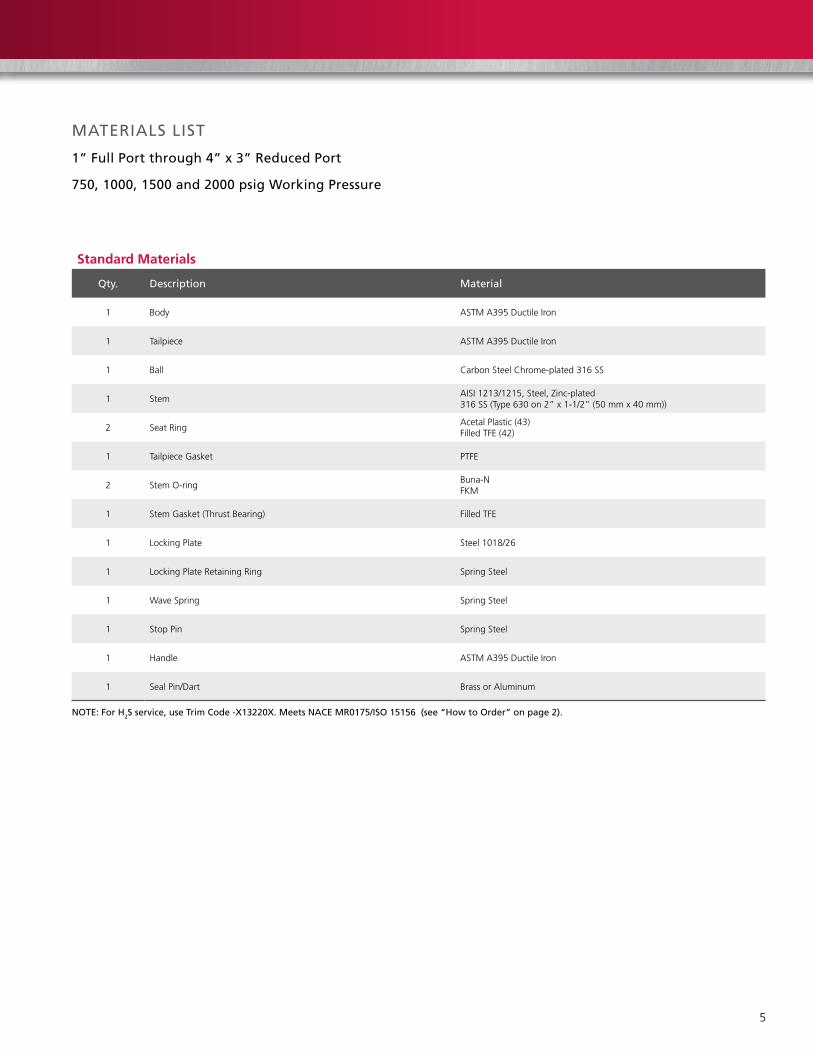
Standard Materials
• APIlinepipethreads
• Body:Ductileiron
• BallandStem:Carbonsteelorstainlesssteel
• SeatandSeals:Acetalplastic/Buna-N
optional Materials
• BallandStem:Stainlesssteel
• SeatandSeals:TFE/FKM
Compliances
• ASMEB16.5
• MSS-SP-6,25,55,72and61
• NACEMR0175/ISO15156
• API607Fire-testSpecification
ASME Pressure ClassesSize Classes
in. (mm) 750 1000 1500 2000
1 (25) FP • •
2x1-1/2 (50 x 40) RP • • • •
2 (50) FP • • •
2-1/2x2 (65 x 50) RP • •
3 x 2 (80 x 50) RP • • • •
3 (80) FP • • •
4 x 3 (100 x 80) RP • • •
5
MateRIalS lISt
1” Full Port through 4” x 3” Reduced Port
750, 1000, 1500 and 2000 psig Working Pressure
Standard Materials
Qty. Description Material
1 Body ASTMA395DuctileIron
1 Tailpiece ASTMA395DuctileIron
1 Ball CarbonSteelChrome-plated316SS
1 StemAISI1213/1215,Steel,Zinc-plated 316SS(Type630on2”x1-1/2”(50mmx40mm))
2 Seat RingAcetal Plastic (43) Filled TFE (42)
1 TailpieceGasket PTFE
2 StemO-ringBuna-NFKM
1 StemGasket(ThrustBearing) Filled TFE
1 LockingPlate Steel 1018/26
1 LockingPlateRetainingRing Spring Steel
1 Wave Spring Spring Steel
1 Stop Pin Spring Steel
1 Handle ASTMA395DuctileIron
1 Seal Pin/Dart Brass or Aluminum
note: For H2S service, use trim Code -X13220X. Meets naCe MR0175/ISo 15156 (see “How to order” on page 2).

6
DIMenSIonS anD WeIgHtS
1” Full Port through 4” x 3” Reduced Port
DimensionsSize in. Dimension a
B C e F g(mm) threaded grooved1 FP 4.00 – 1.00 1.00 2.77 4.0 7.1
(25 FP) (102) – (25) (25) (70) (102) (180)
2 RP 5.55 5.25 1.50 2.00 3.56 4.9 7.1
(50 RP) (141) (133) (38) (50) (90) (124) (180)
2 FP 6.00 – 2.00 2.00 4.50 4.9 15.0
(50 FP) (152) – (51) (50) (114) (124) (381)
2-1/2RP 7.00 – 2.00 2.50 4.50 4.9 15.0
(65 RP) (178) – (51) (65) (114) (124) (381)
3 RP 7.25 7.25 2.00 3.00 4.50 4.9 15.0
(80 RP) (184) (184) (51) (80) (114) (124) (381)
3 FP 8.75 – 3.00 3.00 5.66 6.0 15.0
(80 FP) (222) – (76) (80) (144) (152) (381)
4 RP 8.75 8.88 3.00 4.00 5.66 6.0 15.0
(100 RP) (222) (226) (76) (100) (144) (152) (381)
note: the dimensions are approximated.
Weights – Full PortValve Size (in.) and Weight (lb)
operation 1 x 1 2 x 2 3 x 3Without Handle 4.0 14.4 42.8
With Handle 4.5 17.6 46.0
Valve Size (mm) and Weight (kg)operation 25 x 25 50 x 50 80 x 80
Without Handle 1.8 6.5 19.4
With Handle 2.0 8.0 20.9
Weights – Reduced PortValve Size (in.) and Weight (lb)
operation 2 x 1-1/2 2-1/2 x 2 3 x 2 4 x 3Without Handle 9.4 15.5 16.6 35.5
With Handle 9.9 18.0 19.8 38.7
Valve Size (mm) and Weight (kg)operation 50 x 40 65 x 50 80 x 50 100 x 80
Without Handle 4.3 7.0 7.5 16.1
With Handle 4.5 8.2 9.0 17.6
F
B
g
B C
e
aa
g
F
e
Full Port (FP) Reduced Port (RP)
Bore Dia.
Bore Dia. Pipe

7
WKM DynaSeal 310 Floating Ball ValvestRIM guIDelIneS FoR all DynaSeal 310 ValVeS
Thischartisanabbreviatedguidetothechemicalresistanceandpressure/temperaturelimitationsofthesealmaterialsusedintheWKMDynaSeal310floatingballvalve.ConsultCameronregardingquestionsabouttrimselections.
Seal Code
Seat Materialtailpiece gasket
Service application
01 TFE TFE
SeatandtailpiecegasketsareofvirginTFE.Usewhereladingcontaminationfromglassorotherfillersisnotdesirable,suchasinfoodservice.Recommendedforlow-temperatureserviceto-50°F(-46°C). Also recommended for vacuum service.
42 Filled TFE TFE
Seat material is TFE filled with inert materials for use at elevated temperatures and pressures. SamechemicalresistanceasvirginTFEexceptslightlyaffectedbyhotconcentratedalkalinesolutions. Some chlorinated compounds can cause swelling. Goodforvacuumservice.Alsorecommendedforlow-temperatureservice-50°F(-46°C).
43 Homopolymer Acetal Plastic TFE Forgeneraluseathighpressurestoatemperatureof220°F(104°C).
48 Homopolymer Acetal Plastic Filled TFEForgeneraluseathighpressurestoatemperatureof220°F(104°C).Usedonsocketweldendvalves3”(80mm)boresizeandsmaller.
07 *FKM/SS TFE
High-andlow-pressureblock-and-bleed. Generaluseforlow-pressureandabrasionresistance. Notsuitableforsteam.Goodforvacuumservice. Availableinboresizesto3”(80mm).
18 HPT-2 Filled TFE
HPT-2isaspecialTFEformulationforuseattemperaturesabovetrim42capability. Best suited for constant temperature or constant pressure applications. Provenserviceinsteam,hotoil,heattransferfluids,hotresinsandboilerfeed water. Same chemical resistance as TFE. Slightlyaffectedbyhot,concentratedalkalinesolutions. Some fluorinated compounds cause swelling.
23 Celcon TFE
Foruseinhigh-pressureapplications. Temperaturelimitedto225°F(107°C)(1/4”to3/4”(8mmto20mm)boresonly).
28 Filled TFE Filled TFESameas42,excepttailpiecegasketisfilledTFE. Usedonweldendvalves4”(100mm)andlarger.
60S NickelAlloyHVOF/316 Graphite Metal-to-metalQPQballandseatmadeofnickelalloyover316SS.
92H ChromeCarbide/316 Graphite Metal-to-metalballandseatmadeofchromecarbideover316SS.note 1: trim 07 and 18 should be tested for each application by actual use.note 2: all seal codes, with the exception of 07, have been fire-tested (and qualified) to aPI 607 4th edition requirements.* trim sizes smaller than 1-1/2” (40 mm) in trim 07 are 100% elastomeric. Sizes 1-1/2” (40 mm) and larger are elastomeric with a metal insert.

8
HoW to oRDeR
NACEMR0175/ISO15156Compliance–Materialsofconstructionshallbeincompliancewiththepre-qualifiedmaterialrequirementsspecifiedbyNACEMR0175/ISO15156.AccordingtoNACEMR0175/ISO15156,itisthemanufacturer’sresponsibilityformeeting metallurgical requirements and the customer/user responsibilitytoensurethatamaterialwillbesatisfactoryintheintended environment. When given the application requirements (environment)bythecustomer/user,CameroncanmaketechnicalrecommendationsinaccordancewithNACEMR0175/ISO15156,butthatinnowaycertifiesorwarrantstheproductormaterialsforthe application.
2 R B 1 X X C S 4 3 S 2 W R
Size(in.)
PortReducedPort=R
FullPort=F
ValveType*
Body Tailpiece Code
SealCode
Ball and StemCode
ActuatorCode
Material CodeCarbonsteel CS
316 Stainless steel S1
Type 630 S2*
* See chart below.† not all trim combinations are possible. Consult factory for availability and for materials not listed.
Material CodesCarbonsteel CS
ControlledhardnesscarbonsteelforH2S service CS2*
SameasCS2,butspecialfor-50°F(-46°C)service CS3*
316 stainless steel for wetted parts S1
316stainlesssteelwithstainlesssteelexternaltrim;goodfor-50°F(-46°C) S8*
* naCe 4” (100 mm) RP and smaller. type 630 stem, 316 stainless steel ball.
actuator CodeWrench* WR
Oval Handwheel OH
Worm Gear WG
Bare Stem BS
Less Gear LG
Less Wrench LW* Wrenches are part of the valve assembly
on 4R bore and smaller valves. In 4” F through 8” x 6” (100 mm F through 200 x 150 mm), they are sold separately.
* Meets naCe *MR0175/ISo 15156.
Seal number Seal Material tailpiece gasket Material01 PTFE PTFE
42 Filled PTFE PTFE
43 Homopolymer Acetal Plastic PTFE
07 FKM PTFE
18 HPT-2 Filled PTFE
23 Celcon PTFE
28 Filled PTFE Filled PTFE
60S 316w/NickelAlloyHVOF Graphite
92H 316w/ChromeCarbide Graphite
310 Two-piece Valve TypeSize 150 RF 300 RF 600 RF 600 RJ
in. (mm) lP SP lP SP1 (25) FP B110 – B128 – B182 B172
1-1/2 (40) FP B110 – B128 – B182 B172
2 (50) RP B100 – B120 – B114 B170
2 (50) FP B110 – B128 – B182 B172
3 x 2 (80 x 50) RP B100 – B120 – B114 B170
3 (80) FP B110 – B128 – B182 B172
4 (100) RP B100 – B120 – B114 B170
4 (100) FP B110 – B128 – B182*** B172***
6 (150) RP – B102 B120 – B114*** B170***
6 (150) FP B110 B113 B128 – B182*** B172***
8 (200) RP B100 B102 – B122 B114*** B170***
*** the 4” (100 mm) and larger sizes are available in trim CS2-43-S2-Wga (worm gear-operated) only.
310 Two-piece Valve TypeSize
Female thread Male X Femalein. (mm)1/4 (8) FP B138 –
3/8 (10) FP B138 –
1/2 (15) RP B136 –
1/2 (15) FP B138 –
3/4 (20) FP B138 B138 (M x F)**
1 (25) RP B136 B136 (M x F)**
1 (25) FP B138 –
1-1/2 (40) FP B138 –
2 (50) RP B136 –
2 (50) FP B138 –
3 (80) RP B138 –
3 (80) FP B138 –
4 (100) RP B136 –
** available in body tailpiece code S8 only. note: threaded end valves have nPt internal pipe thread in full conformance with aSMe B2.1 and Federal thread Handbook H-28.
310 Three-piece Valve TypeSize
Socket Weldin. (mm)1/4 (8) FP B103
3/8 (10) FP –
3/4 (20) FP B103
1 (25) RP B106
1-1/2 (40) FP B103
2 (50) RP B106
9
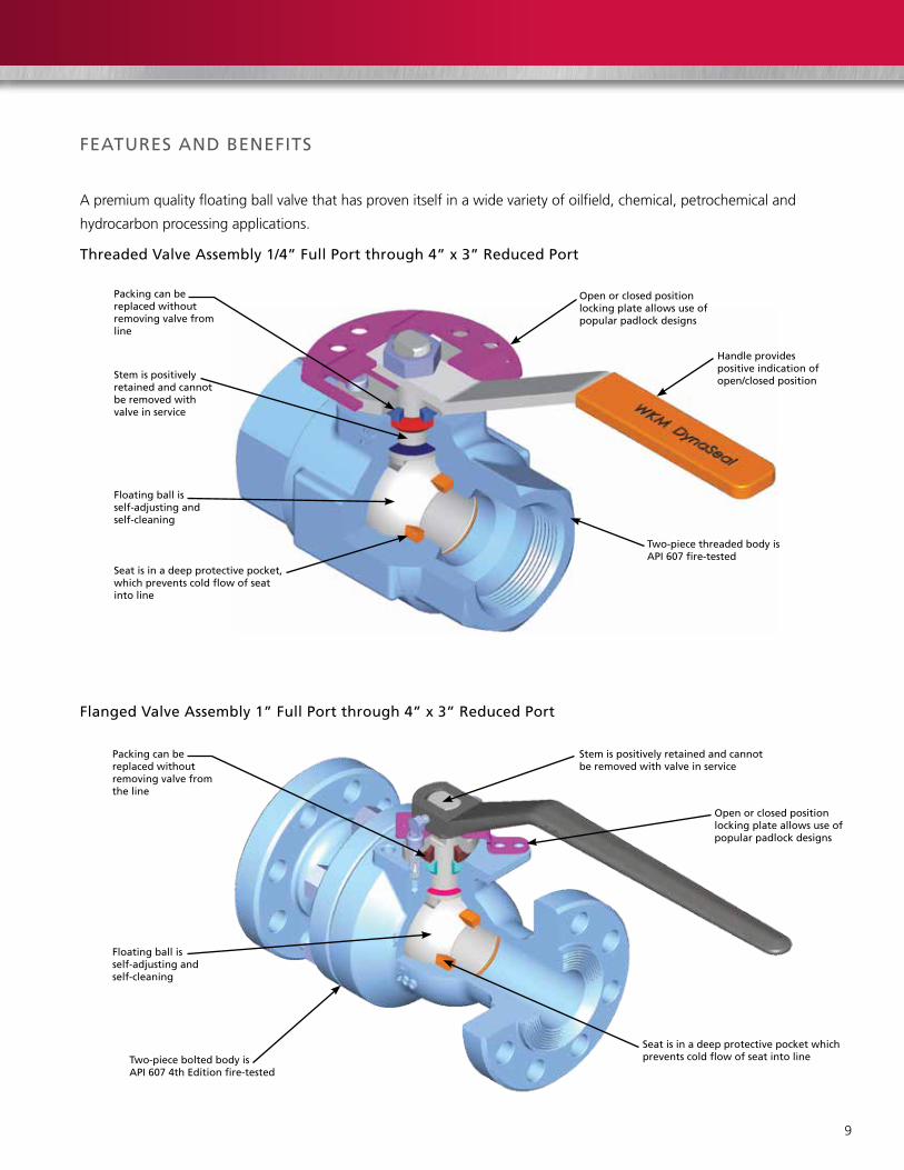
FeatuReS anD BeneFItS
open or closed positionlocking plate allows use of popular padlock designs
Apremiumqualityfloatingballvalvethathasprovenitselfinawidevarietyofoilfield,chemical,petrochemicaland
hydrocarbonprocessingapplications.
Floating ball is self-adjusting and self-cleaning
two-piece threaded body is aPI 607 fire-tested
Stem is positively retained and cannot be removed withvalve in service
Packing can be replaced without removing valve from line
threaded Valve assembly 1/4” Full Port through 4” x 3” Reduced Port
Handle providespositive indication ofopen/closed position
Seat is in a deep protective pocket, which prevents cold flow of seat into line
open or closed positionlocking plate allows use of popular padlock designs
Floating ball is self-adjusting and self-cleaning
two-piece bolted body is aPI 607 4th edition fire-tested
Stem is positively retained and cannot be removed with valve in service
Packing can be replaced without removing valve from the line
Seat is in a deep protective pocket which prevents cold flow of seat into line
Flanged Valve assembly 1” Full Port through 4” x 3” Reduced Port

10
FeatuReS anD BeneFItS (ContInueD)
WKMDynaSeal310floatingballvalvessatisfyawide
rangeofapplicationsandareavailableinavarietyof
standardandoptionalmaterials,insizesfrom1/4”(8mm)
to4”x3”(100mmx80mm)andworkingpressuresto
5000psi.Engineeredforheavy-duty,maintenance-free
performance,theDynaSeal310ballvalveispreferredfor
use in critical applications.
Sour Oil and Gas Service
WKMDynaSealballvalvesaresuitedtoapplicationswithin
gathering lines, manifolds and field processing units in
souroilandgasfields.Theycanbetrimmedtoconform
withNACEMR0175/ISO15156.
Deep-recessed Seats
The WKM DynaSeal 310 seat is protected in a machined
recessordeeppocketthatsurroundsandprotectsthe
seat. This design eliminates cold flow into the valve
conduitandavoidspotentialseatdamagefromball
movement or flow media.
Trim 42 Seats
Seats are manufactured of filled TFE and rated to 1500 psi
MOP.Withworkingtemperaturesto500°F(260°C)and
low-torqueoperation,theseseatssatisfyeventhemost
difficult of processing requirements.
Trim 43 Seats
Seats are manufactured of acetal plastic and are rated to
3000psiMOPandworkingtemperaturesto220°F
(104°C).Theseseatsaredesignedtohandlethemost
demanding applications. They can flex under pressure and
provideaconsistentrangeoflow-torqueoperations.They
alsoprovideafullfacesealagainsttheballandmultiple
sealsagainstthetopandbackofthepockettoprovidea
positive seal.
Socket Weld end310 Ball Valve

11
Adjustable, Replaceable Packing
Thein-linevalvestempackingconsistsofPTFE
impregnatedgraphitewithanimperviousmetalbarrier
andasecondarytaperedmetalbackup.Thepackingis
field-adjustableandneverrequireslubrication.The
packingandthestainlesssteelcapcanbereplaced
without removing the valve from the line.
Positively Retained Stem
Thestemispositivelyretainedwithashoulder.Itcannot
beremovedwiththevalveinservice.TherearenoO-rings
used in this design.
Floating Ball Design Delivers Tight Seal
Thegroundandpolishedballisfreetofloatandmates
perfectlywiththeconicalseatsforapositive,leakproof
seal.Self-cleaningandself-adjusting,theballalsois
pressure activated – the higher the line pressure, the
tighter the seal.
Fire-tested for Safety
AllWKMDynaSeal310ballvalvesarequalifiedunderAPI
Standard607.Thepocketedseatandlocked-instem
designcontributestoitsfire-testedcharacteristics.Should
thesoftseatsbedestroyedbyfire,theballfloatsdown
stream,providingatightmetal-to-metalsealagainstthe
lipoftheseatpocket.Ifthetailpiecesealsaredestroyed,
themetal-to-metaltailpiece-to-bodyconnectionretards
externalleakage.
Indicator Handle
The design of the handle permits installation on the stem
inthecorrectpositiononly,inalignmentwiththeball
port. When the handle is aligned with the pipe, the valve
is open. When the handle is perpendicular to the pipe, the
valve is closed.
Locking Devices
Lockingdevicesarestandardonall4”x3”(100mmx
80 mm) and smaller manually operated valves and permit
lockingineithertheopenorclosedpositions.

12
SPeCIFICatIonS
tailpiece
Body
Ball
Seat Ring
tailpiece gasket
tailpiece
tailpiece gasket
Seat Ring
Capscrew
Bonnet Cap
Compression Ring
Packing
Stem Seal
Stem
Handle(oval Handwheel available)
lock nut
Socket Weld ends
Standards and Specifications
Sizes
• 1/4”(8mm)fullport
• 3/4”(20mm)fullport
• 1”(25mm)reducedport
• 1-1/2”(40mm)fullport
• 2”(50mm)reducedport
Working Pressure
• 3000psiwithtrim48
operating temperatures
• From-20°Fto220°F(-29°Cto104°C)
end Connections
• Socketweldends
Standard Material
Body
• CarbonsteelandcarbonsteelNACEMR0175/ ISO15156
Ball/Stem
• Carbonsteelorstainlesssteel
Seats
• Trim48(acetalplasticseats)
Industry Standards Compliance
• ASMEB16.34
• MSS-SP-25,55,72
• API607Fire-testSpecification

13
Ball
Capscrew
Bonnet Cap
Handle
lock nut
1/4” (8 mm) Full Port to1” (25 mm) Reduced Port
tailpiece
Seat Ring
Body
tailpiece gasket
Seat Ring
Capscrew
Bonnet Cap
Compression Ring
Packing
Stem Seal
Stem
Handle(oval Handwheel available)
lock nut
Stop Plate
threaded Connections
threaded ends C5
Threaded ConnectionsFull Port
SizeReduced Port
Size
in. (mm) in. (mm)
1/4 (8) 1/2 (15)
3/8 (10) 1 (25)
1/2 (15) 2 (50)
3/4 (20) 3 (80)
1 (25) 4 (100)
1-1/2 (40)
2 (50)
3 (80)
Standards and Specifications
• To5000psiinsmallsizes
• Trim43pressurerangeto3000psiin1/4”(8mm)to 3” x 2” (80 mm x 50 mm) threaded end valves
Operating Temperatures
• From-50°Fto600°F(-46°Cto316°C)
Standard Material
Body
• Carbonsteelandstainlesssteel
Ball/Stem
• Carbonsteelandstainlesssteel
Seat/Seal trims
• TFE,filledTFE,acetalplastic,HPT-2and316stainlesssteelwithchromiumcarbideandFKM
Industry Compliance
• ASMEB16.5,B16.34
• MSS-SP-6,25,55,72
• API607Fire-testSpecifications
• GOST-R

14
SPeCIFICatIonS
Ball
tailpiece
Seat Ring
tailpiece gasket
Body Stud
Body
Capscrew
Bonnet Cap
Retainer Ring
Compression Packing
Packing
Stem
Handle
Stop Plate
Stem Seal
Seat Ring
Body nut
Bolt
Flanged Connections
Flanged ends 310F
Flanged Connections ASME Pressure ClassSize Class
in. (mm) 150 300 600
1 (25) FP • • •
1-1/2 (40) FP • • •
2x1-1/2 (50 x 40) RP • • •
2 (50) FP • • •
3 x 2 (80 x 50) RP • • •
3 (80) FP • • •
4 x 3 (100 x 80) RP • • •
Operating Temperatures
• From-50°Fto600°F(-46°Cto316°C)
Standard Material
Body
• Carbonsteelandstainlesssteel
Ball/Stem
• Carbonsteelandstainlesssteel
Seat/Seal trims
• TFE,filledTFE,acetalplastic,HPT-2and316stainlesssteelwithchromiumcarbideandFKM
Industry Compliance
• ASMEB16.5,B16.34
• MSS-SP-6,25,55,72
• API607Fire-testSpecifications
• GOST-R
15
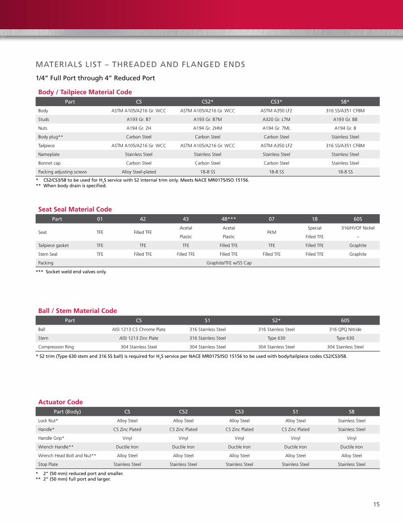
Body / Tailpiece Material CodePart CS CS2* CS3* S8*
Body ASTMA105/A216Gr.WCC ASTMA105/A216Gr.WCC ASTM A350 LF2 316SS/A351CF8M
Studs A193 Gr. B7 A193 Gr. B7M A320 Gr. L7M A193 Gr. B8
Nuts A194 Gr. 2H A194 Gr. 2HM A194 Gr. 7ML A194 Gr. 8
Body plug** CarbonSteel CarbonSteel CarbonSteel Stainless Steel
Tailpiece ASTMA105/A216Gr.WCC ASTMA105/A216Gr.WCC ASTM A350 LF2 316SS/A351CF8M
Nameplate Stainless Steel Stainless Steel Stainless Steel Stainless Steel
Bonnet cap CarbonSteel CarbonSteel CarbonSteel Stainless Steel
Packingadjustingscrews AlloySteel-plated 18-8SS 18-8SS 18-8SS
MateRIalS lISt – tHReaDeD anD FlangeD enDS
1/4” Full Port through 4” Reduced Port
Seat Seal Material CodePart 01 42 43 48*** 07 18 60S
Seat TFE Filled TFEAcetal Acetal
FKMSpecial 316/HVOFNickel
Plastic Plastic Filled TFE –
Tailpiecegasket TFE TFE TFE Filled TFE TFE Filled TFE Graphite
Stem Seal TFE Filled TFE Filled TFE Filled TFE Filled TFE Filled TFE Graphite
Packing Graphite/TFEw/SSCap
Ball / Stem Material CodePart CS S1 S2* 60S
Ball AISI1213CSChromePlate 316 Stainless Steel 316 Stainless Steel 316QPQNitride
Stem AISI1213ZincPlate 316 Stainless Steel Type 630 Type 630
CompressionRing 304 Stainless Steel 304 Stainless Steel 304 Stainless Steel 304 Stainless Steel
Actuator CodePart (Body) CS CS2 CS3 S1 S8
LockNut* Alloy Steel Alloy Steel Alloy Steel Alloy Steel Stainless Steel
Handle* CSZincPlated CSZincPlated CSZincPlated CSZincPlated Stainless Steel
Handle Grip* Vinyl Vinyl Vinyl Vinyl Vinyl
Wrench Handle** DuctileIron DuctileIron DuctileIron DuctileIron DuctileIron
Wrench Head Bolt and Nut** Alloy Steel Alloy Steel Alloy Steel Alloy Steel Alloy Steel
Stop Plate Stainless Steel Stainless Steel Stainless Steel Stainless Steel Stainless Steel
* CS2/CS3/S8 to be used for H2S service with S2 internal trim only. Meets naCe MR0175/ISo 15156.** When body drain is specified.
*** Socket weld end valves only.
* S2 trim (type 630 stem and 316 SS ball) is required for H2S service per naCe MR0175/ISo 15156 to be used with body/tailpiece codes CS2/CS3/S8.
* 2” (50 mm) reduced port and smaller.** 2” (50 mm) full port and larger.

16
Bore Dia.
a
1” (25 mm) Full Port through
2” (50 mm) Reduced Port
J
X
H
Stem Dimensions
DIMenSIonal Data – 4” ReDuCeD PoRt anD SMalleR
1/4” Full Port through 4” Reduced Port: Flanged, threaded and Socket Weld
B136/B138 Threaded
B100/B110Class150Raised-faceFlanges B120/B128Class300Raised-faceFlanges B114/B182Class600Raised-faceFlanges
B170/B172Class600RingjointFlanges B106/B103SocketWeld
1” (25 mm) Reduced Port and Smaller
2” (50 mm) Full Port through
4” (100 mm) Reduced Port
J
Q
S
t
g
W
F
B
e
C
D
Dia.
Bore Dia.
a
J
X
H
Stem Dimensions
J
t
S
R
g
WF
B
e
C
D
Dia.
Bore Dia.
a
J
g
H
Stem DimensionsJ
t
S
Q
g
WF
B
e
B
D
Bore Dia.
F
e
X
W
C
a
D
Dia.
17
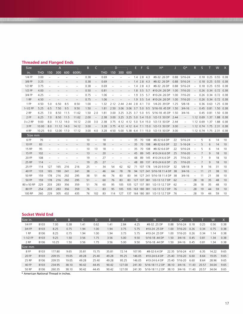
Threaded and Flanged EndsSize a B C D e F g H* J Q* R S t W X
in. tHD 150 300 600 600RJ tHD 150 300 6001/4 FP 3.00 – – – – 0.38 – 0.69 – – – 1.4 2.8 4.3 #8-32.26DP 0.88 5/16-24 – 0.18 0.25 0.55 0.38
3/8 FP 3.25 – – – – 0.38 – 0.69 – – – 1.4 2.8 4.3 #8-32.26DP 0.88 5/16-24 – 0.18 0.25 0.55 0.38
1/2 RP 3.75 – – – – 0.38 – 0.69 – – – 1.4 2.8 4.3 #8-32.26DP 0.88 5/16-24 – 0.18 0.25 0.55 0.38
1/2 FP 4.00 – – – – 0.50 – 0.81 – – – 1.8 3.5 5.7 #10-24.26DP 1.00 7/16-20 – 0.26 0.34 0.72 0.38
3/4 FP 4.25 – – – – 0.75 – 1.06 – – – 1.9 3.5 5.7 #10-24.26DP 1.00 7/16-20 – 0.26 0.34 0.72 0.38
1 RP 4.50 – – – – 0.75 – 1.06 – – – 1.9 3.5 5.4 #10-24.26DP 1.00 7/16-20 – 0.26 0.34 0.72 0.38
1 FP 4.50 5.0 6.50 8.5 8.50 1.00 – 1.32 2.12 2.44 2.44 2.8 4.1 7.0 1/4-20.39DP 1.25 5/8-18 – 0.36 0.63 1.25 0.38
1-1/2FP 5.25 6.5 7.50 9.5 9.50 1.50 – 1.81 2.50 3.06 3.06 3.7 5.0 9.5 5/16-18.45DP 1.50 3/4-16 – 0.45 0.81 1.50 0.38
2 RP 6.25 7.0 8.50 11.5 11.62 1.50 2.0 1.81 3.00 3.25 3.25 3.7 5.0 9.5 5/16-18.45DP 1.50 3/4-16 – 0.45 0.81 1.50 0.38
2 FP 6.25 7.0 8.50 11.5 11.62 2.00 – 2.38 3.00 3.25 3.25 5.0 5.4 15.0 1/2-13.50DP 2.44 – 1.12 0.69 1.37 1.88 0.38
3 x 2 RP 9.00 8.0 11.12 14.0 14.12 2.00 3.0 2.38 3.75 4.12 4.12 5.0 5.4 15.0 1/2-13.50DP 2.44 – 1.12 0.69 1.37 1.88 0.38
3 FP 10.00 8.0 11.12 14.0 14.12 3.00 – 3.28 3.75 4.12 4.12 6.4 7.1 15.0 1/2-13.50DP 3.00 – 1.12 0.74 1.75 2.31 0.38
4 RP 10.25 9.0 12.00 17.0 17.12 3.00 4.0 3.28 4.50 5.00 5.38 6.4 7.1 15.0 1/2-13.50DP 3.00 – 1.12 0.74 1.75 2.31 0.38
Size mm6 FP 76 – – – – 10 – 18 – – – 35 70 108 #8-326.6DP 22 5/16-24 – 5 6 14 10
10 FP 83 – – – – 10 – 18 – – – 35 70 108 #8-326.6DP 22 5-16-24 – 5 6 14 10
15 RP 95 – – – – 10 13 18 – – – 35 70 108 #8-326.6DP 22 5/16-24 – 5 6 14 10
15 FP 102 – – – – 13 – 20 – – – 45 89 145 #10-246.6DP 25 7/16-20 – 7 9 18 10
20 FP 108 – – – – 19 – 27 – – – 48 89 145 #10-246.6DP 25 7/16-20 – 7 9 18 10
25 RP 114 – – – – 19 25 27 – – – 48 89 137 #10-246.6DP 25 7/16-20 – 7 9 18 10
25 FP 114 127 165 216 216 25 – 34 54 62 62 71 107 178 1/4-209.9DP 32 5/8-18 – 9 16 31 10
40 FP 133 165 190 241 241 38 – 46 64 78 78 94 127 241 5/16-1811.4DP 38 3/4-16 – 11 21 38 10
50 RP 159 178 216 292 295 38 51 46 76 83 83 94 127 241 5/16-1811.4DP 38 3/4-16 – 11 21 38 10
50 FP 159 178 216 292 295 51 – 60 76 83 83 127 137 381 1/2-1312.7DP 62 – 28 18 35 48 10
80 x 50 RP 229 203 283 356 359 51 76 60 95 105 105 127 137 381 1/2-1312.7DP 62 – 28 18 35 48 10
80 FP 254 203 283 356 359 76 – 83 95 105 105 163 180 381 1/2-1312.7DP 76 – 28 19 44 59 10
100 RP 260 229 305 432 435 76 102 83 114 127 137 164 180 381 1/2-1312.7DP 76 – 28 19 44 59 10
Socket Weld EndSize in. a B C D e F g H J Q* S t W X
1/4 FP B103 7.00 0.38 1.41 0.62 1.41 2.84 4.25 #8-32.25DP 0.88 5/16-24 0.18 0.25 0.56 0.38
3/4 FP B103 8.25 0.75 1.94 1.00 1.94 3.75 5.75 #10-24.25DP 1.00 7/16-20 0.26 0.34 0.75 0.38
1 RP B106 8.25 0.75 1.94 1.00 1.94 3.75 5.75 #10-24.25DP 1.00 7/16-20 0.26 0.34 1.14 0.38
1-1/2FP B103 9.25 1.50 3.56 1.75 3.56 5.00 9.50 5/16-18.44DP 1.50 3/4-16 0.45 0.81 1.34 0.38
2 RP B106 10.25 1.50 3.56 1.75 3.56 5.00 9.50 5/16-18.44DP 1.50 3/4-16 0.45 0.81 1.34 0.38
Size mm8 FP B103 177.80 9.65 35.81 15.75 35.81 72.14 107.95 #8-326.4DP 22.35 5/16-24 4.57 6.35 14.22 9.65
20 FP B103 209.55 19.05 49.28 25.40 49.28 95.25 146.05 #10-246.4DP 25.40 7/16-20 6.60 8.64 19.05 9.65
25 RP B106 209.55 19.05 49.28 25.40 49.28 95.25 146.05 #10-246.4DP 25.40 7/16-20 6.60 8.64 28.96 9.65
40 FP B103 234.95 38.10 90.42 44.45 90.42 127.00 241.30 5/16-1811.2DP 38.10 3/4-16 11.43 20.57 34.04 9.65
50 RP B106 260.35 38.10 90.42 44.45 90.42 127.00 241.30 5/16-1811.2DP 38.10 3/4-16 11.43 20.57 34.04 9.65
* american national thread in inches.
18
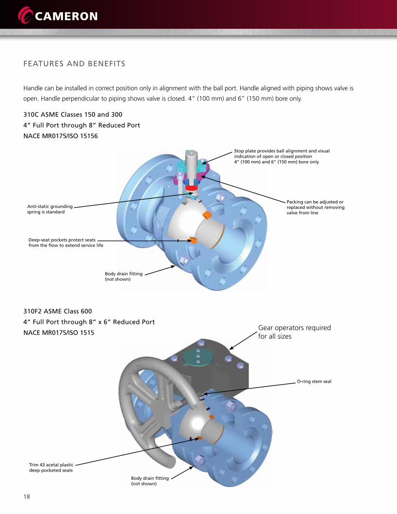
310C aSMe Classes 150 and 300
4” Full Port through 8” Reduced Port
naCe MR0175/ISo 15156
FeatuReS anD BeneFItS
Stop plate provides ball alignment and visual indication of open or closed position4” (100 mm) and 6” (150 mm) bore only
Handlecanbeinstalledincorrectpositiononlyinalignmentwiththeballport.Handlealignedwithpipingshowsvalveis
open.Handleperpendiculartopipingshowsvalveisclosed.4”(100mm)and6”(150mm)boreonly.
anti-static grounding spring is standard
Packing can be adjusted or replaced without removing valve from line
Deep-seat pockets protect seats from the flow to extend service life
o-ring stem seal
trim 43 acetal plasticdeep-pocketed seats
Body drain fitting(not shown)
310F2 aSMe Class 600
4” Full Port through 8” x 6” Reduced Port
naCe MR0175/ISo 1515
Body drain fitting(not shown)
Gear operators required forallsizes

19
WKMDynaSeal310ballvalvessatisfyawiderangeof
applications.Availableinavarietyofstandardand
optionalmaterials,theymaybespecifiedinsizesfrom4”
(100 mm) to 8” x 6” (200 mm x 150 mm) and ASME
Class150and300.ASMEClass600isavailableinsizes4”
(100 mm) through 8” x 6” (200 mm x 150 mm).
Engineeredforheavy-duty,maintenance-free
performance,theWKMDynaSeal310ballvalveis
commonly selected for a variety of applications in virtually
any industry.
Chemical and Petrochemical Plants
There is a wide range of chemical and petrochemical
applicationsforWKMDynaSeal310ballvalves.Theyare
serving in many plastic plants, handling such slurries as
40%vinylchlorideinhigh-pressurecatalystlines;andin
processes, handling dry lading such as polyethylene and
polystyrene powders.
There are hundreds of applications in such plants where WKM
DynaSeal310ballvalvesareprovidingefficientservice.
Refining
TheWKMDynaSeal310ballvalveisidealfortherefining
industry.Themanymetalseats,sealsandavailabletrims
offer the versatility needed to handle the wide variety of
products used in the refining process.
High-temperature Service
Specialhigh-temperaturetrimsareavailableforWKM
DynaSeal310ballvalves,whichprovideforserviceto
600°F(316°C).Thistrimisdesignedforsteamservice,
hotoil,heattransferfluids,boilerfeedwaterand
similar applications.
Low-temperature Service
Standardtrimsaccommodatetemperaturesto-20°F
(-29°C).Fortemperaturesto-50°F(-46°C),please
consult factory.
WKM DynaSeal 310 ball valve with pneumatic actuator
Maintenance-free Performance
Undermostconditions,theWKMDynaSeal310ballvalve
willprovideyearsoftrouble-freeservicewithno
maintenance required.
Insomesevereapplications,suchashandlingextremely
abrasiveslurriesathightemperature,itmaybenecessary
to replace the seats occasionally.
Seatandsealkitsareavailable,andreplacementcanbe
done easily with ordinary tools.
Sour Oil and Gas Service
WKMDynaSeal310ballvalveshaveservedforyearsin
gathering lines, manifolds and field processing units in
souroilandgasfields.Theycanbetrimmedtoconform
withNACEMR0175/ISO15156.
Actuation-friendly
Avarietyofactuatortypescanbeinstalledeasily,including
pneumatic, hydraulic, diaphragm, vane, electromechanical
and electrohydraulic.
Fire-tested for Safety
AllWKMDynaSeal310ballvalvesarequalifiedunderAPI
Standard607.Thepocketedseatandlocked-instem
designcontributestoitsfire-testedcharacteristics.Should
thesoftseatsbedestroyedbyfire,theballfloatsdown
stream,providingatightmetal-to-metalsealagainstthe
lipoftheseatpocket.Ifthetailpieceseals
aredestroyed,themetal-to-metaltailpiece-to-body
connectionretardsexternalleakage.

20
FeatuReS anD BeneFItS (ContInueD)
Deep-recessed Seats
Theseatisrecessedintoadeepmachinedpocketthat
surrounds and protects the seat on all sides. This design
eliminates cold flow into the valve conduit, where it can
bedamagedbytheactionoftheballortheflowmedium.
The result is long and extended service life.
Teflon Body Seal
ATeflonbodysealisusedbetweenthevalvebodyand
tailpiece.
Adjustable, Replaceable Packing
Thein-linevalvestempackingthroughASMEclass300
consistsofPTFEimpregnatedgraphitewithametalbarrier.
Thepackingisfield-adjustableandvirtuallyneverrequires
lubrication.Thepackingandthestainlesssteelcapcanbe
replaced without removing the valve from line.
Fugitive Emissions
WKMDynaSeal310ballvalvesthroughASMEClass300
canbesuppliedandcertifiedtomeettherequirementsof
fugitiveemissionsasregulatedbyThe1990Amendment
toTheCleanAirActto100ppm.
Positively Retained Stem
Thestemispositivelyretainedandcannotberemoved
with the valve in service.
Indicator Handle
The design of the handle ASME class 300 permits
installation on the stem in the correct position only, in
alignmentwiththeballport.Whenthehandleisaligned
with the pipe, the valve is open. When the handle is
perpendicular to the pipe, the valve is closed.
Floating Ball Design Delivers Tight Seal
Thegroundandpolishedballisfreetofloatandmates
perfectlywiththeconicalseatsforapositive,leakproof
seal.Self-cleaningandself-adjusting,theballalsois
pressure activated – the higher the line pressure, the
tighter the seal.
4” FP to 8” RP
(100 mm FP to 200 mm RP)
ASMEClasses150/300
Gear Mounting Brackets For:
21
Gear Mounting Brackets For:
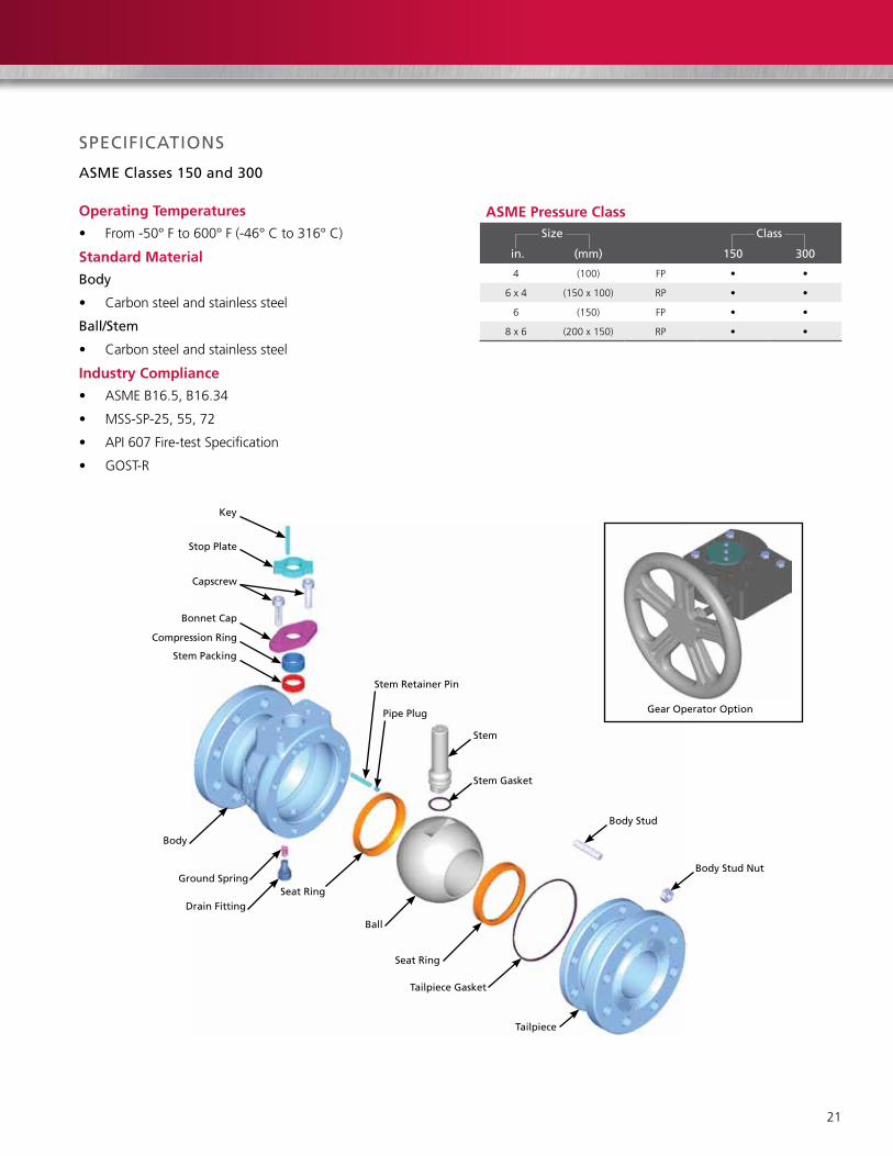
SPeCIFICatIonS
aSMe Classes 150 and 300
Ball
tailpiece
Seat Ring
tailpiece gasket
Seat Ring
Key
Stop Plate
Capscrew
Bonnet Cap
gear operator option
ground Spring
Body
Drain Fitting
Compression Ring
Stem Packing
Stem Retainer Pin
Pipe Plug
Stem
Stem gasket
Body Stud
Body Stud nut
Operating Temperatures
• From-50°Fto600°F(-46°Cto316°C)
Standard Material
Body
• Carbonsteelandstainlesssteel
Ball/Stem
• Carbonsteelandstainlesssteel
Industry Compliance
• ASMEB16.5,B16.34
• MSS-SP-25,55,72
• API607Fire-testSpecification
• GOST-R
ASME Pressure ClassSize Class
in. (mm) 150 300
4 (100) FP • •
6 x 4 (150 x 100) RP • •
6 (150) FP • •
8 x 6 (200 x 150) RP • •

22
SPeCIFICatIonS
aSMe Class 600
Ball
tailpiece
Seat Ring
tailpiece gasket
Seat Ring
Worm gear operator
ground Spring
Body
Drain Fitting
Handwheel
Washer
nut Stem o-ring
Stem gasket
Key
Stem
Body Stud
Body Stud nut
Stud
Operating Temperatures
• From-20°Fto220°F(-29°Cto104°C)
Standard Material
Body
• Carbonsteel
Ball/Stem
• Carbonsteelandstainlesssteel
Industry Compliance
• ASMEB16.5,B16.34
• MSS-SP-25,55,72
• API607Fire-testSpecification
• GOST-R
ASME Pressure ClassSize Class
in. (mm) 600
4 (100) FP •
6 x 4 (150 x 100) RP •
6 (150) FP •
8 x 6 (200 x 150) RP •
23
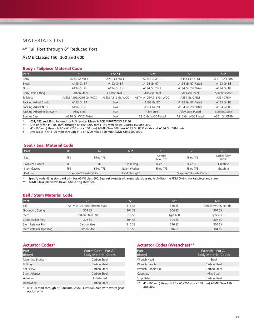
MateRIalS lISt
4” Full Port through 8” Reduced Port
aSMe Classes 150, 300 and 600
Body / Tailpiece Material CodePart CS CS1*‡ CS2* S1 S8*Body A216Gr.WCC A216Gr.WCC A216Gr.WCC A351Gr.CF8M A351Gr.CF8M
Studs A193 Gr. B7 A192 Gr. B7 A193 Gr. B7 † A193 Gr. B7 Plated A193 Gr. B8
Nuts A194 Gr. 2H A194 Gr. 2H A194 Gr. 2H † A194 Gr. 2H Plated A194 Gr. B8
Body Drain Fitting CarbonSteel CarbonNACE Stainless Steel Stainless Steel Stainless Steel
Tailpiece ASTMA105/A216Gr.WCC ASTMA216Gr.WCC ASTMA105/A216Gr.WCC A351Gr.CF8M A351CF8M
PackingAdjustStuds A193 Gr. B7 N/A A193 Gr. B7 A193 Gr. B7 Plated A193 Gr. B8
PackingAdjustNuts A194 Gr. 2H N/A A194 Gr. 2H A194 Gr. 2H Plated A194 Gr. B8
PackingAdjustingScrews** Alloy Steel N/A Alloy Steel Alloy Steel Plated Stainless Steel
BonnetCap A216Gr.WCCPlated N/A A216Gr.WCCPlated A216Gr.WCCPlated A351Gr.CF8M
* CS1, CS2 and S8 to be used for H2S service. Meets naCe MR0175/ISo 15156.** use only for 4” (100 mm) through 8” x 6” (200 mm x 150 mm) aSMe Classes 150 and 300.† 4” (100 mm) through 8” x 6” (200 mm x 150 mm) aSMe Class 600 uses a193 gr. B7M studs and a194 gr. 2HM nuts.‡ available in 4” (100 mm) through 8” x 6” (200 mm x 150 mm) aSMe Class 600 only.
Seat / Seal Material CodePart 01 42 43* 18 28 60S
Seat TFE Filled TFE –Special
Filled TFEFilled TFE
NickelAlloy HVOF
TailpieceGasket TFE TFE FKMO-ring Filled TFE Filled TFE Graphite
StemGasket TFE Filled TFE Nylon Washer Filled TFE Filled TFE Graphite
Packing Graphite/TFEwithSSCap FKMO-ring** Graphite/TFEwithSSCap
* Specify code 43 as standard trim for aSMe class 600. Seal set consists of: acetal plastic seats, high-fluorine FKM o-ring for tailpiece and stem.** aSMe Class 600 valves have FKM o-ring stem seal.
Ball / Stem Material CodePart CS S1 S2* 60SBall ASTMA105HardChromePlate 316 SS 316 SS 316SSw/QPQNitride
Grounding Spring 304 SS 304 SS 304 SS 304 SS
Stem CarbonSteelENP 316 SS Type 630 Type 630
CompressionRing 304 SS 304 SS 304 SS 304 SS
Stem Retainer Pin CarbonSteel 316 SS 316 SS 304 SS
Stem Retainer Pipe Plug CarbonSteel 316 SS 316 SS 304 SS
Actuator Codes*Part (Body)
Worm gear – For all Body Material Codes
MountingBracket CarbonSteel
Bolting CarbonSteel
Set Screw CarbonSteel
Stem Adapter CarbonSteel
Actuator As Selected
Handwheel CarbonSteel
Actuator Codes (Wrenches)**Part (Body)
Wrench – For all Body Material Codes
Wrench Head Steel
Wrench Handle CarbonSteel
Wrench Handle Pin CarbonSteel
Capscrew Alloy Steel
Stop Plate CarbonSteel
* 4” (100 mm) through 8” (200 mm) aSMe Class 600 sold with worm gear option only.
** 4” (100 mm) through 8” x 6” (200 mm x 150 mm) aSMe Class 150 and 300.

24
DIMenSIonal Data – 4” Full PoRt anD laRgeR
4” Full Port through 8” Reduced Port
aSMe Classes 150, 300 and 600
Full Port DimensionsSize in. a B C D H K l M P R
4 17.00 4.00 4.00 6.52 6.81 16.00 2.50 9.72 9.79 8.18
6 22.00 6.00 6.00 8.17 9.28 20.00 4.84 14.26 13.43 11.25
Size mm100 432 102 102 166 173 508 64 247 249 208
150 559 152 152 208 236 610 123 362 341 286
Reduced Port DimensionsSize in. a B C D H K l M P R
6 x 4 22.00 4.00 6.00 6.52 6.81 16.00 2.50 9.72 9.79 8.18
8 x 6 26.00 6.00 8.00 8.17 9.28 20.00 4.84 14.26 13.43 11.25
Size mm150 x 100 559 102 152 166 173 508 64 247 249 208
200 x 150 660 152 203 208 236 610 123 362 341 286
aSMe Class 600
Valve with Wrench (lever)4” (100 mm) through
8” x 6” (200 mm x 150 mm)aSMe Classes 150/300
a
g
Dia.
y
F
C
X
e
B
D
Bore Dia.
thread Sizethread Depth
Z
aa
Dia. J
= Key sizen
R
a
P
H
M
l
K
Valve with gear 4” (100 mm) through 8” x 6” (200 mm x 150 mm) aSMe Class 600 (less gear option not available) Dia.
l
He
u through Hole Dia.W
V
PR
D
a
BBore Dia
Valve with gear4” (100 mm) through 8” x 6” (200 mm x 150 mm)
aSMe Classes 150/300
Mounting Bracket4” FP to 8” RP
(100 mm FP to 200 mm RP)aSMe Classes 150/300

25
Full Port Dimensionsa* Class
Size
150 RF 300 RF 300
long Short long Short BW B C D e F g H J K l M n P R u V W X y Z aa
in. B110 B113 B128 B134 B150
49.00
N/A–
N/A– 4.0 4.0 6.47 8.63 9.88 36.0 7.56 1.250 6.0 2.80 7.88 0.250 10.84 9.15 0.56 2.44 4.921 1.88 4.63 3/8-16NC 0.63
– 12.00 12.00 4.0 4.0 6.47 8.63 9.88 36.0 7.56 1.250 6.0 2.80 8.12 0.250 10.84 9.15 0.56 2.44 4.921 1.88 4.63 3/8-16NC 0.63
615.50 10.50 –
N/A– 6.0 6.0 8.20 11.38 12.63 48.0 9.44 1.500 12.0 2.80 10.95 0.375 12.72 11.03 0.56 2.44 4.921 1.88 4.63 3/8-16NC 0.63
– – 15.88 15.88 6.0 6.0 8.20 11.38 12.63 48.0 9.44 1.500 14.0 4.11 13.24 0.375 13.28 11.33 0.56 2.44 4.921 1.88 4.63 3/8-16NC 0.63
mma* Class
Size
150 RF 300 RF 300
long Short long Short BW B C D e F g H J K l M n P R u V W X y Z aa
B110 B113 B128 B134 B150
100229
N/A–
N/A– 102 102 164 219 251 914 192 31.75 150 71 200 6.35 275 232 14 62 124.99 48 118 3/8-16NC 16
– 305 305 102 102 164 219 251 914 192 31.75 150 71 206 6.35 275 232 14 62 124.99 48 118 3/8-16NC 16
150394 267 –
N/A– 152 152 208 289 321 1219 240 38.1 356 71 278 9.53 323 280 14 62 124.99 48 118 3/8-16NC 16
– – 403 403 152 152 208 289 321 1219 240 38.1 300 104 336 9.53 337 280 14 62 124.99 48 118 3/8-16NC 16
Reduced Port Dimensionsa* Class
Size
150 RF 300 RF
long Short long Short B C D e F g H J K l M n P R u V W X y Z aa
in. B100 B102 B120 B122
6 x 4 N/A10.5 –
N/A4.0 6.0 6.45 8.63 9.88 36.0 7.56 1.25 6.0 2.8 7.88 0.25 10.84 9.15 0.56 2.44 4.921 1.88 4.63 3/8-16NC 0.63
– 15.88 4.0 6.0 6.45 8.63 9.88 36.0 7.56 1.25 6.0 2.8 8.12 0.25 10.84 9.15 0.56 2.44 4.921 1.88 4.63 3/8-16NC 0.63
8 x 618.0 11.5
N/A– 6.0 8.0 8.2 11.38 12.63 48.0 9.44 1.5 14.0 2.8 10.95 0.375 12.72 11.03 0.56 2.44 4.921 1.88 4.63 3/8-16NC 0.63
– – 16.50 6.0 8.0 8.2 11.38 12.63 48.0 9.44 1.5 16.0 4.11 11.11 0.375 13.28 11.33 0.56 2.44 4.921 1.88 4.63 3/8-16NC 0.63
mma* Class
Size
150 RF 300 RF
long Short long Short B C D e F g H J K l M n P R u V W X y Z aa
B100 B102 B120 B122
150 x 100
N/A267 –
N/A102 152 164 219 251 914 192 31.75 150 71 200 6.35 275 232 14 62 124.99 48 118 3/8-16NC 16
– 403 102 152 164 219 251 914 192 31.75 150 71 206 6.35 275 232 14 62 124.99 48 118 3/8-16NC 16
200 x 150
457 292N/A
– 152 203 208 289 321 1219 240 38.1 356 71 278 9.53 323 280 14 62 124.99 48 118 3/8-16NC 16
– – 419 152 203 208 289 321 1219 240 38.1 406 104 282 9.53 337 288 14 62 124.99 48 118 3/8-16NC 16
* Center line-to-face dimension is half of dimension a, except: 4” (100 mm) aSMe class 150 Full Port – stem is offset 1/2” (12.7 mm) towards body end and 6” (150 mm). aSMe class 150 Full Port long Pattern – stem is offset 2-1/2” (63.5 mm) towards body end.
26
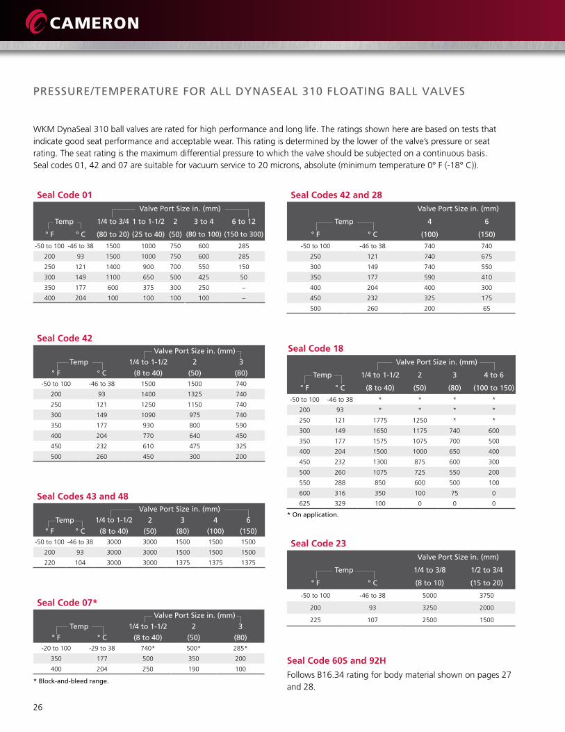
PReSSuRe/teMPeRatuRe FoR all DynaSeal 310 FloatIng Ball ValVeS
WKMDynaSeal310ballvalvesareratedforhighperformanceandlonglife.Theratingsshownherearebasedonteststhatindicategoodseatperformanceandacceptablewear.Thisratingisdeterminedbythelowerofthevalve’spressureorseatrating.Theseatratingisthemaximumdifferentialpressuretowhichthevalveshouldbesubjectedonacontinuousbasis. Sealcodes01,42and07aresuitableforvacuumserviceto20microns,absolute(minimumtemperature0°F(-18°C)).
Seal Code 01 Valve Port Size in. (mm)
temp 1/4 to 3/4 1 to 1-1/2 2 3 to 4 6 to 12
° F ° C (80 to 20) (25 to 40) (50) (80 to 100) (150 to 300)
-50to100 -46to38 1500 1000 750 600 285
200 93 1500 1000 750 600 285
250 121 1400 900 700 550 150
300 149 1100 650 500 425 50
350 177 600 375 300 250 –
400 204 100 100 100 100 –
Seal Codes 42 and 28 Valve Port Size in. (mm)
temp 4 6
° F ° C (100) (150)
-50to100 -46to38 740 740
250 121 740 675
300 149 740 550
350 177 590 410
400 204 400 300
450 232 325 175
500 260 200 65
Seal Code 42 Valve Port Size in. (mm)
temp 1/4 to 1-1/2 2 3
° F ° C (8 to 40) (50) (80)-50to100 -46to38 1500 1500 740
200 93 1400 1325 740
250 121 1250 1150 740
300 149 1090 975 740
350 177 930 800 590
400 204 770 640 450
450 232 610 475 325
500 260 450 300 200
Seal Code 18 Valve Port Size in. (mm)
temp 1/4 to 1-1/2 2 3 4 to 6
° F ° C (8 to 40) (50) (80) (100 to 150)
-50to100 -46to38 * * * *
200 93 * * * *
250 121 1775 1250 * *
300 149 1650 1175 740 600
350 177 1575 1075 700 500
400 204 1500 1000 650 400
450 232 1300 875 600 300
500 260 1075 725 550 200
550 288 850 600 500 100
600 316 350 100 75 0
625 329 100 0 0 0Seal Codes 43 and 48 Valve Port Size in. (mm)
temp 1/4 to 1-1/2 2 3 4 6
° F ° C (8 to 40) (50) (80) (100) (150)-50to100 -46to38 3000 3000 1500 1500 1500
200 93 3000 3000 1500 1500 1500
220 104 3000 3000 1375 1375 1375
Seal Code 07* Valve Port Size in. (mm)
temp 1/4 to 1-1/2 2 3
° F ° C (8 to 40) (50) (80)-20to100 -29to38 740* 500* 285*
350 177 500 350 200
400 204 250 190 100
* Block-and-bleed range.
Seal Code 23 Valve Port Size in. (mm)
temp 1/4 to 3/8 1/2 to 3/4
° F ° C (8 to 10) (15 to 20)
-50to100 -46to38 5000 3750
200 93 3250 2000
225 107 2500 1500
* on application.
Seal Code 60S and 92H
FollowsB16.34ratingforbodymaterialshownonpages27and 28.
27
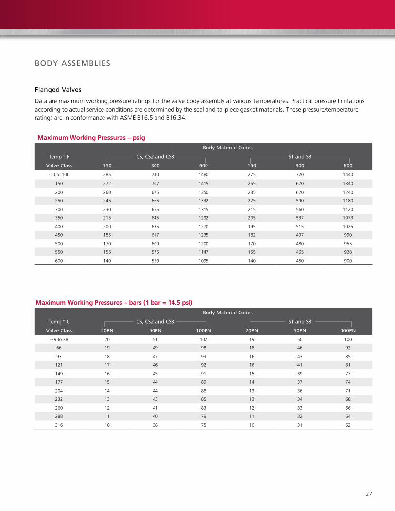
BoDy aSSeMBlIeS
Flanged Valves
Dataaremaximumworkingpressureratingsforthevalvebodyassemblyatvarioustemperatures.Practicalpressurelimitationsaccordingtoactualserviceconditionsaredeterminedbythesealandtailpiecegasketmaterials.Thesepressure/temperatureratings are in conformance with ASME B16.5 and B16.34.
Maximum Working Pressures – psigBody Material Codes
temp ° F CS, CS2 and CS3 S1 and S8
Valve Class 150 300 600 150 300 600
-20to100 285 740 1480 275 720 1440
150 272 707 1415 255 670 1340
200 260 675 1350 235 620 1240
250 245 665 1332 225 590 1180
300 230 655 1315 215 560 1120
350 215 645 1292 205 537 1073
400 200 635 1270 195 515 1025
450 185 617 1235 182 497 990
500 170 600 1200 170 480 955
550 155 575 1147 155 465 928
600 140 550 1095 140 450 900
Maximum Working Pressures – bars (1 bar = 14.5 psi)Body Material Codes
temp ° C CS, CS2 and CS3 S1 and S8
Valve Class 20Pn 50Pn 100Pn 20Pn 50Pn 100Pn
-29to38 20 51 102 19 50 100
66 19 49 98 18 46 92
93 18 47 93 16 43 85
121 17 46 92 16 41 81
149 16 45 91 15 39 77
177 15 44 89 14 37 74
204 14 44 88 13 36 71
232 13 43 85 13 34 68
260 12 41 83 12 33 66
288 11 40 79 11 32 64
316 10 38 75 10 31 62

28
BoDy aSSeMBlIeS (ContInueD)
threaded Valves
BodyTrimCodeS8andCS3aresuitableforserviceto-50°F(-46°C).Allothertrimsarelimitedtooperatingtemperaturesnolowerthan-20°F(-29°C).Thesepressure/temperatureratingsareinconformancewithASMEB16.5,B16.34.
Maximum Working Pressures – psigtemp ° F Body Material Codes
Valve Bore CS, CS2 and CS3 S1 and S8
Size in. 1/4 to 3/8 1/2 to 3/4 1 to 1-1/2 2 3 1/4 to 3/8 1/2 to 3/4 1 to 1-1/2 2 3
-20to100 5000 3750 3000 2000 1500 5000 3750 3000 2000 1500
150 4779 3583 2867 1912 1434 4650 3487 2790 1861 1396
200 4557 3416 2734 1824 1368 4301 3224 2580 1722 1292
250 4494 3368 2696 1800 1350 4092 3068 2455 1639 1229
300 4431 3320 2658 1775 1333 3884 2912 2330 1556 1167
350 4355 3264 2613 1744 1310 3725 2794 2236 1491 1117
400 4278 3209 2567 1713 1287 3566 2677 2141 1426 1068
450 4161 3120 2496 1665 1252 3442 2583 2066 1377 1031
500 4043 3031 2425 1618 1216 3317 2489 1992 1328 995
550 3868 2900 2320 1548 1163 3225 2419 1936 1291 966
600 3694 2768 2215 1478 1110 3134 2349 1880 1254 938
Maximum Working Pressures – bars (1 bar = 14.5 psi)temp ° C Body Material Codes
Valve Bore CS, CS2 and CS3 S1 and S8
Size mm 8 to 10 15 to 20 25 to 40 50 80 8 to 10 15 to 20 25 to 40 50 80
-29to38 345 259 207 138 103 345 259 207 138 103
66 330 247 198 132 99 321 240 192 128 96
93 314 236 189 126 94 297 222 178 119 89
121 310 232 186 124 93 282 212 169 113 85
149 306 229 183 122 92 268 201 161 107 80
177 300 225 180 120 90 257 193 154 103 77
204 295 221 177 118 89 246 185 148 98 74
232 287 215 172 115 86 237 178 143 95 71
260 279 209 167 112 84 229 172 137 92 69
288 267 200 160 107 80 222 167 134 89 67
316 255 191 153 102 77 216 162 130 86 65
29
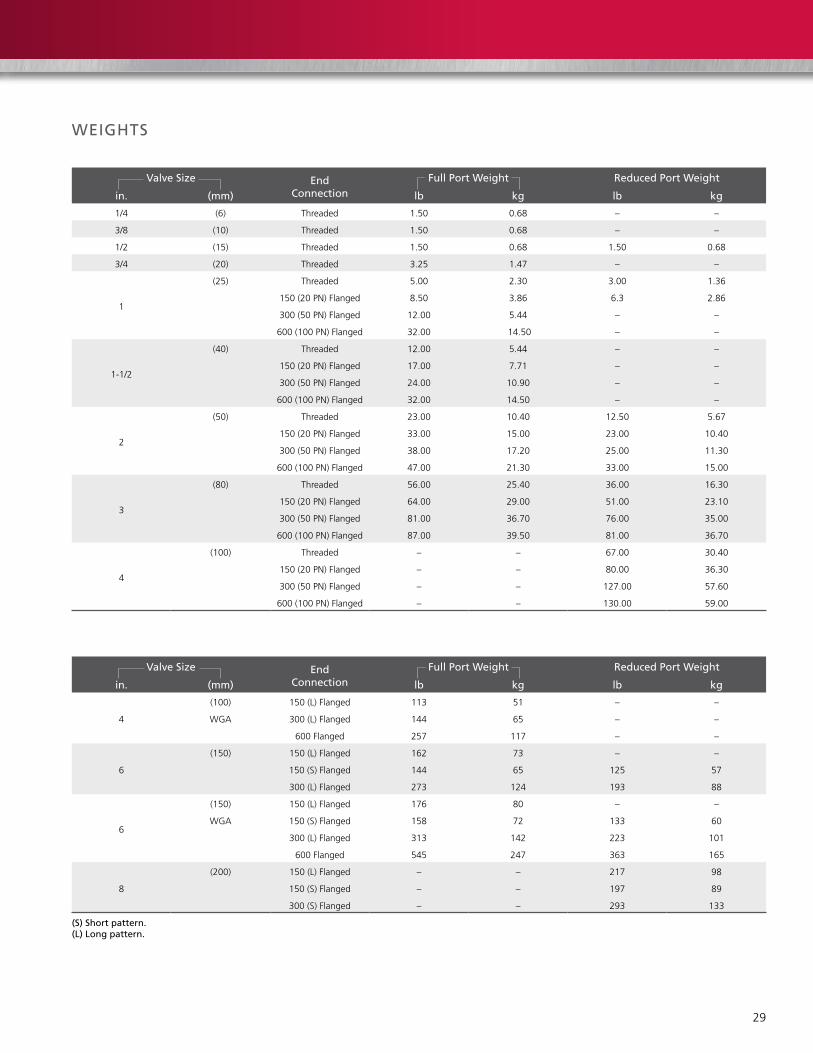
Valve Size end Connection
Full Port Weight Reduced Port Weight
in. (mm) lb kg lb kg
1/4 (6) Threaded 1.50 0.68 – –
3/8 (10) Threaded 1.50 0.68 – –
1/2 (15) Threaded 1.50 0.68 1.50 0.68
3/4 (20) Threaded 3.25 1.47 – –
1
(25) Threaded 5.00 2.30 3.00 1.36
150 (20 PN) Flanged 8.50 3.86 6.3 2.86
300 (50 PN) Flanged 12.00 5.44 – –
600 (100 PN) Flanged 32.00 14.50 – –
1-1/2
(40) Threaded 12.00 5.44 – –
150 (20 PN) Flanged 17.00 7.71 – –
300 (50 PN) Flanged 24.00 10.90 – –
600 (100 PN) Flanged 32.00 14.50 – –
2
(50) Threaded 23.00 10.40 12.50 5.67
150 (20 PN) Flanged 33.00 15.00 23.00 10.40
300 (50 PN) Flanged 38.00 17.20 25.00 11.30
600 (100 PN) Flanged 47.00 21.30 33.00 15.00
3
(80) Threaded 56.00 25.40 36.00 16.30
150 (20 PN) Flanged 64.00 29.00 51.00 23.10
300 (50 PN) Flanged 81.00 36.70 76.00 35.00
600 (100 PN) Flanged 87.00 39.50 81.00 36.70
4
(100) Threaded – – 67.00 30.40
150 (20 PN) Flanged – – 80.00 36.30
300 (50 PN) Flanged – – 127.00 57.60
600 (100 PN) Flanged – – 130.00 59.00
Valve Size end Connection
Full Port Weight Reduced Port Weight
in. (mm) lb kg lb kg
4
(100) 150 (L) Flanged 113 51 – –
WGA 300 (L) Flanged 144 65 – –
600 Flanged 257 117 – –
6
(150) 150 (L) Flanged 162 73 – –
150 (S) Flanged 144 65 125 57
300 (L) Flanged 273 124 193 88
6
(150) 150 (L) Flanged 176 80 – –
WGA 150 (S) Flanged 158 72 133 60
300 (L) Flanged 313 142 223 101
600 Flanged 545 247 363 165
8
(200) 150 (L) Flanged – – 217 98
150 (S) Flanged – – 197 89
300 (S) Flanged – – 293 133
WeIgHtS
(S) Short pattern. (l) long pattern.

30
WeIgHtS (ContInueD)
Valve Size
Male x Female threaded ends
Full Port Weights Reduced Port Weights
in. (mm) MoP lb kg lb kg
1/2 (15) 3000 – – 3 1.36
1/2 (15) 5000 – – 3 1.36
3/4 (20) 3000 6 2.72 – –
3/4 (20) 3750 6 2.72 – –
1 (25) 3000 – – 7 3.18
1 (25) 3750 – – 7 3.18
Socket Weld ends
1/4 (8) 3000 2 0.91 – –
3/4 (20) 3000 6 2.72 – –
1 (25) 3000 – – 6 2.72
1-1/2 (40) 3000 19 8.62 – –
2 (50) 3000 – – 21 9.53
FloW CHaRaCteRIStICS (CV)*
Valve Size and Port Size threaded Valve Pressure Class
in. (mm) end Valves 150 300 600
1/4 x 1/4 (8 x 8) 9 – – –
3/8 x 3/8 (10 x 10) 9 – – –
1/2 x 3/8 (15 x 10) 5 – – –
1/2 x 1/2 (15 x 15) 16 16 14 –
3/4 x 1/2 (20 x 15) – 10 10 –
3/4 x 3/4 (20 x 20) 45 – – –
1 x 3/4 (25 x 20) 20 35 34 –
1 x 1 (25 x 25) 93 88 77 68
1-1/2x1-1/2 (40 x 40) 248 223 208 184
2x1-1/2 (50 x 40) 80 102 101 99
2 x 2 (50 x 50) 491 464 421 362
3 x 2 (80 x 50) 107 117 133 133
3 x 3 (80 x 80) 1099 1228 1042 928
4 x 3 (100 x 80) 322 359 410 406
4 x 4 (100 x 100) – 2118 2446 –
6 x 4 (150 x 100) – 390 391 (S) –
6 x 6 (150 x 150) – 5403 6644 (S) / 5468 (L) –
8 x 6 (200 x 150) – 1215 1219 (S) / 1215 (L) –
* Flow of water in uS gallons per minute per 1 psi pressure drop across a fully open valve. (S) Short pattern. (l) long pattern.

31
SteM toRQueS (in-lb)
Seat Seal Code 01Valve Bore Size Differential Pressure
in. (mm) 0 to 285 500 740 1000 1500
1/4 to 3/8 (8 to 10) 36 36 36 36 42
1/2 (15) 60 60 60 72 72
3/4 (20) 90 90 90 120 180
1 (25) 120 150 180 225 –
1-1/2 (40) 240 330 420 520 –
2 (50) 500 640 810 – –
3 (80) 1200 1800 2400 – –
Seat Seal Code 42**Valve Bore Size Differential Pressure
in. (mm) 0 to 285 500 740 1000 1500
1/4 to 3/8 (8 to 10) 36 36 36 36 42
1/2 (15) 60 60 60 72 72
3/4 (20) 90 90 90 120 180
1 (25) 120 150 180 225 300
1-1/2 (40) 240 330 420 520 720
2 (50) 500 640 810 1090 1440
3 (80) 1200 1800 2400 – –
Seat Seal Codes 43 and 48Valve Bore Size Differential Pressure
in. (mm) 0 to 285 500 740 1000 1500 2000 2250 2500 3000
1/4 to 3/8 (8 to 10) 48 48 48 50 55 60 70 85 100
1/2 (15) 58 60 64 70 90 120 140 165 215
3/4 (20) 90 95 105 125 175 230 260 295 370
1 (25) 225 245 260 280 320 400 455 520 700
1-1/2 (40) 390 410 450 510 700 920 1050 1200 1550
2 (50) 860 960 1075 1210 1500 1830 2000 2200 2600
3 (80) 1450 1635 1885 2220 3050 – – – –
Seat Seal Code 18Valve Bore Size Differential Pressure
in. (mm) 0 to 285 500 740 1000 1500 2250
1/4 to 3/8 (8 to 10) 60 60 60 60 72 84
1/2 (15) 60 60 60 70 84 108
3/4 (20) 128 128 145 160 215 360
1 (25) 274 284 312 360 405 580
1-1/2 (40) 520 580 680 810 980 1390
2 (50) 910 1042 1240 1500 1765 2300
3 (80) 1200 1800 2400 2900 3420 –
Seat Seal Code 07Valve Bore Size liquid Dry gas
in. (mm) 0 to 285 0 to 285 740
1/4 to 3/8 (8 to 10) 36 42 113
1/2 (15) 60 82 220
3/4 (20) 90 150 404
1 (25) 180 336 606
1-1/2 (40) 420 840 2260
2 (50) 900 1200 3230
3 (80) 2400 3600 9690
** Multiply trim 42 torque by two for seat seal code 60S and 92H.

32
SteM toRQueS (in-lb) (ContInueD)
Seat Seal Code 01Valve Bore Size Differential Pressure
in. (mm) 0 to 285 500 740
4 (100) 2090 3300 4200
6 (150) 4400 8200 11,200
Seat Seal Code 23Valve Bore Size Differential Pressure
in. (mm) 0 to 285 500 740 1000 1500 2000 2250 2500 3000 3500 3750 4000 4500 5000
1/4 to 3/8 (8 to 10) 60 60 60 60 60 65 70 85 100 115 125 130 150 165
1/2 (15) 70 70 70 82 110 125 140 180 220 276 310 – – –
3/4 (20) 108 108 125 140 190 260 340 420 560 695 800 – – –
Seat Seal Codes 28 and 42Valve Bore Size Differential Pressure
in. (mm) 0 to 285 500 740
4 (100) 2400 3300 4200
6 (150) 5400 8200 11,200
NOTE: Thetorquevalueslistedfor285psiandgreaterarebasedonvalvescontrollingtheflowofcleanlubricatingliquidatambienttemperature. For valves at pressures less than 285 psi, use the value for 285 psi. Interpolationmaybeusedforanypressureabove285psi,butlessthanmaximumpressurelisted.
Runningtorquevalueswillaveragetwo-thirdsofthesevalues. Forrunningtorquevalueslessthanbreakawaytorquevaluesat285psi,usebreakawaytorquevalues. Re-seatingtorqueisequaltobreakawaytorque. Foroperatingtemperaturesbetween-20°Fand-50°F(-29°Cand-46°C),multiplythesevaluesby1.20. These torque values do not contain service or safety factors. Actuatorselectionshouldbemadebasedonexperienceandappropriateserviceandsafetyfactors.

33
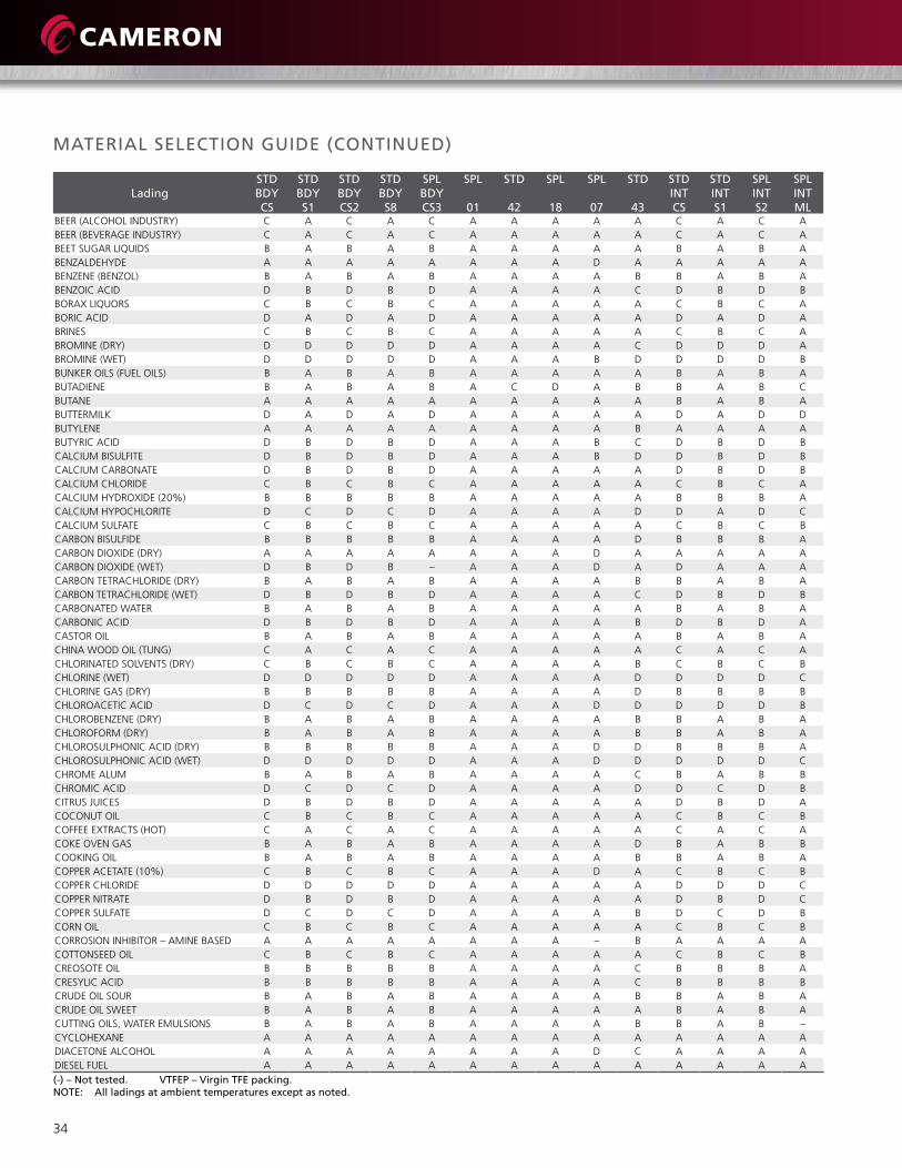
WKM DynaSeal 210 and 310 Floating Ball ValvesMateRIal SeleCtIon guIDe
Aselectionofbody,stemandseat/sealmaterialsforWKMDynaSealvalvesareavailable.Thefollowinglistisintendedasaguideintheselectionofmaterialsforcorrosiveservice.Nomaterialcanbeexpectedtoresistthecorrosiveactionofallthemanyladings found in modern industry. Experience has shown, however, that certain materials can perform satisfactorily within certain limits.Thephysicalpropertiesofamaterialareaffecteddifferentlybyeachcorrosivemedium.Therefore,itsometimesbecomesnecessary to sacrifice value in another property. As a result, the user must decide which property is of prime importance for his application.Internalmovingparts,incontactwiththelading,should always carry an “A” rating. Body materials with exposure to corrosive ladings can sometimescarrya“B”ratingbecausemetallossduetocorrosiveisnotascritical.
Thefollowinginformationisdesignedforusebytechnicallyqualifiedindividualsattheir owndiscretionandrisk.Westronglyrecommendthattestsberununderactualoperating conditionstoobtainamaterial’sperformanceabilityinanyonecorrosivemedium.
Rating Interpretation:
“A” – Excellent“B”–Good(slightlyattacked)“C”–Fair(moderatelyattacked)“D” – Not recommended
ladingStD BDy CS
StD BDy S1
StD BDy CS2
StD BDy S8
SPl BDy CS3
SPl
01
StD
42
SPl
18
SPl
07
StD
43
StD IntCS
StD IntS1
SPl IntS2
SPl IntMl
ACETALDEHYDE C A C A C A A A D B C A C AACETATESOLVENTS A A A A A A A A D B A A A AACETICACID(30%) C A C A C A A A B D C A C AACETICACID(AERATED) D A D A D A A A D D D A D AACETICACID(AIR-FREE) D A D A D A A A D D D B D AACETICACID(CRUDE) C A C A C A A A D D C A C AACETICANHYDRIDE D B D B D A A A D D D B D AACETONE A A A A A A A A D B A A A AACETYLENE(DRYONLY) A A A A A A A A A D A A A AACRYLONITRILE A A A A A A A A C C A A A AALCOHOL-AMYL B A B A B A A A B B B A B AALCOHOL-BUTYL B A B A B A A A A C B A B AALCOHOL-ETHYL B A B A B A A A C B B A B AALCOHOL-METHYL(METHANOL) B A B A B A A A D C B A B AALUMINUMCHLORIDE(DRY) B A B A B A A A A D B A B AALUMINUMSULFATE(ALUMS) C A C A C A A A A B C A C AALUMS C A C A C A A A A C C A C AAMINES A A A A A A A A B C A A A AAMINES-BASEDCORROSIONINHIBITOR A A A A A A A A – B A A A AAMINESRICH D A A A A A A A – C D A A AAMMONIA(AQUEOUS) A A A A A A A A D D A A A BAMMONIAANHYDROUS A A A A A A A A D D A A A BAMMONIASOLUTIONS B A B A B A A A D D B A B BAMMONIUMBICARBONATE C B C B C A A A B D C B C BAMMONIUMCARBONATE B B B B B A A A B D B B B BAMMONIUMCHLORIDE D C D C D A A A A B D C D BAMMONIUMHYDROXIDE(28%) C B C B C A C C B C C B C DAMMONIUMHYDROXIDECONCENTRATED C B C B C A C C D D C B C DAMMONIUMMONOPHOSPHATE D B D B D A A A B B D B D CAMMONIUMNITRATE D A D A D A A A C C D A D DAMMONIUMPHOSPHATE(DIBASIC) D B D B D A A A A C D B D CAMMONIUMPHOSPHATE(TRIBASIC) D B D B D A A A A C D B D CAMMONIUMSULFATE C B C B C A A A A A C B C CAMYLACETATE C B C B C A A A D B C B C BANILINE A B A B A A A A C C A B A BANILINEDYES C A C A C A A A B C C A C AANTIMONYTRICHLORIDE D D D D D A A A A D D D D BAPPLEJUICE D B D B D A A A A A D B D AARSENICACID D B D B D A A A A A D B D DASPHALTEMULSION A A A A A A A A A B A A A AASPHALTLIQUID A A A A A A A A A B A A A ABARIUMCARBONATE B B B B B A A A A A B B B BBARIUMCHLORIDE C C C C C A A A A A C C C BBARIUMHYDROXIDE C B C B C A A A A A C B C BBARIUMSULFATE B B B B B A A A A A B B B ABARIUMSULFIDE B B B B – A A A A A C B – B
(-) – not tested. VtFeP – Virgin tFe packing. note: all ladings at ambient temperatures except as noted.
34
MateRIal SeleCtIon guIDe (ContInueD)
ladingStD BDy CS
StD BDy S1
StD BDy CS2
StD BDy S8
SPl BDy CS3
SPl
01
StD
42
SPl
18
SPl
07
StD
43
StD IntCS
StD IntS1
SPl IntS2
SPl IntMl
BEER(ALCOHOLINDUSTRY) C A C A C A A A A A C A C ABEER(BEVERAGEINDUSTRY) C A C A C A A A A A C A C ABEETSUGARLIQUIDS B A B A B A A A A A B A B ABENZALDEHYDE A A A A A A A A D A A A A ABENZENE(BENZOL) B A B A B A A A A B B A B ABENZOICACID D B D B D A A A A C D B D BBORAXLIQUORS C B C B C A A A A A C B C ABORICACID D A D A D A A A A A D A D ABRINES C B C B C A A A A A C B C ABROMINE(DRY) D D D D D A A A A C D D D ABROMINE(WET) D D D D D A A A B D D D D BBUNKEROILS(FUELOILS) B A B A B A A A A A B A B ABUTADIENE B A B A B A C D A B B A B CBUTANE A A A A A A A A A A B A B ABUTTERMILK D A D A D A A A A A D A D DBUTYLENE A A A A A A A A A B A A A ABUTYRICACID D B D B D A A A B C D B D BCALCIUMBISULFITE D B D B D A A A B D D B D BCALCIUMCARBONATE D B D B D A A A A A D B D BCALCIUMCHLORIDE C B C B C A A A A A C B C ACALCIUMHYDROXIDE(20%) B B B B B A A A A A B B B ACALCIUMHYPOCHLORITE D C D C D A A A A D D A D CCALCIUMSULFATE C B C B C A A A A A C B C BCARBONBISULFIDE B B B B B A A A A D B B B ACARBONDIOXIDE(DRY) A A A A A A A A D A A A A ACARBONDIOXIDE(WET) D B D B – A A A D A D A A ACARBONTETRACHLORIDE(DRY) B A B A B A A A A B B A B ACARBONTETRACHLORIDE(WET) D B D B D A A A A C D B D BCARBONATEDWATER B A B A B A A A A A B A B ACARBONICACID D B D B D A A A A B D B D ACASTOROIL B A B A B A A A A A B A B ACHINAWOODOIL(TUNG) C A C A C A A A A A C A C ACHLORINATEDSOLVENTS(DRY) C B C B C A A A A B C B C BCHLORINE(WET) D D D D D A A A A D D D D CCHLORINEGAS(DRY) B B B B B A A A A D B B B BCHLOROACETICACID D C D C D A A A D D D D D BCHLOROBENZENE(DRY) B A B A B A A A A B B A B ACHLOROFORM(DRY) B A B A B A A A A B B A B ACHLOROSULPHONICACID(DRY) B B B B B A A A D D B B B ACHLOROSULPHONICACID(WET) D D D D D A A A D D D D D CCHROMEALUM B A B A B A A A A C B A B BCHROMICACID D C D C D A A A A D D C D BCITRUSJUICES D B D B D A A A A A D B D ACOCONUTOIL C B C B C A A A A A C B C BCOFFEEEXTRACTS(HOT) C A C A C A A A A A C A C ACOKEOVENGAS B A B A B A A A A D B A B BCOOKINGOIL B A B A B A A A A B B A B ACOPPERACETATE(10%) C B C B C A A A D A C B C BCOPPERCHLORIDE D D D D D A A A A A D D D CCOPPERNITRATE D B D B D A A A A A D B D CCOPPERSULFATE D C D C D A A A A B D C D BCORNOIL C B C B C A A A A A C B C BCORROSIONINHIBITOR–AMINEBASED A A A A A A A A – B A A A ACOTTONSEEDOIL C B C B C A A A A A C B C BCREOSOTEOIL B B B B B A A A A C B B B ACRESYLICACID B B B B B A A A A C B B B BCRUDEOILSOUR B A B A B A A A A B B A B ACRUDEOILSWEET B A B A B A A A A A B A B ACUTTINGOILS,WATEREMULSIONS B A B A B A A A A B B A B –CYCLOHEXANE A A A A A A A A A A A A A ADIACETONEALCOHOL A A A A A A A A D C A A A ADIESELFUEL A A A A A A A A A A A A A A(-) – not tested. VtFeP – Virgin tFe packing.note: all ladings at ambient temperatures except as noted.

35
ladingStD BDy CS
StD BDy S1
StD BDy CS2
StD BDy S8
SPl BDy CS3
SPl
01
StD
42
SPl
18
SPl
07
StD
43
StD IntCS
StD IntS1
SPl IntS2
SPl IntMl
DIETHYLAMINE A A A A A A A A HF C A A A ADIPHTALICANHYDROUS – – – – – – A – – – – – – –DOWTHERMS(A-E) B A B A B A A A A B B A B ADRILLINGMUD B A B A B A A A A A B A B ADRIPCOCKS,GAS B A B A B A A A A A B A B ADRYCLEANINGFLUIDS B A B A B A A A A B B A B BEPSOM SALT C B C B C A A A A A C B C BETHANE A A A A A A A A A A A A A AETHANOLAMINE A A A A A A A A D C A A A AETHERS B A B A B – A A D A B A B BETHYLACETATE B B B B B A A A D C B B B BETHYLACRYLATE A A A A A A A A B C A A A AETHYLCHLORIDE(DRY) B A B A B A A A A B B A B BETHYLCHLORIDE(WET) B B B B B A A A A B B B B BETHYLENE(LIQUIDORGAS) A A A A A A – – A B A A A AETHYLENEGLYCOL B B B B B A A A A A B B B BETHYLENEOXIDE B B B B B A A A D B B B B BFATTYACIDS D B D B D A A A A B D B D BFERRICCHLORIDE D D D D D A A A A A D D D CFERRICNITRATE D C D C D A A A A A D C D CFERRICSULFATE D B D B D A A A A A D B D BFERROUSCHLORIDE D D D D D A A A A A D D D CFERROUSSULFATE D B D B D A A A A A D B D BFERROUSSULFATE(SAT) C A C A C A A A – C C A C AFERTILIZERSOLUTIONS B B B B B A A A D D B B B BFISHOILS B A B A B A A A A A B A B AFLUORINE(DRY) B A B A B C C C C C B A B AFLUOROSILICICACID D C D C D A – – A C D C D CFOODFLUIDS–PASTES C A C A C A A A A A C A C AFORMALDEHYDE(COLD) A A A A A A A A D A A A A AFORMALDEHYDE(HOT) D B D B D A A A D B D B D BFORMICACID(COLD) D B D B D A A A C D D B D BFORMICACID(HOT) D D D D D A A A C D D D D BFREON12(DRY) B A B A B A A A B B B A B AFRUITJUICES D A D A D A A A A A D A D AFUELJETJP-4 A A A A A A A A A A A A A AFUELJETJP-5100F A A A A A A A A B A A A A AFUELJETJP-6100F A A A A A A A A B A A A – AFUELOIL B A B A B A A A A A B A B AFUELRP-1 A A A A A A A A A A A A A AFURFURAL A B A B A A A A D B A B A AGALLICACID D B D B D A A A A C D B D BGAS(MANUFACTURED) B B B B B A A A A A B B B AGASODORIZERS(VTFEP) B A B A B A A A A – B A B BGAS,NATURAL B A B A B A A A A A B A B AGASOLINE,AVIATION A A A A A A A A A A A A A AGASOLINE,SOUR B A B A B A A A A B B A B AGASOLINE,LEADED,LOWOCTANE A A A A A A A A A A A A A AGASOLINE,UNLEADED,LOWOCTANE A A A A A A A A A A A A A AGELATIN D A D A D A A A A A D A D AGLUCOSE B A B A B A A A A A B A B AGLUE A A A A A A A A A A A A A AGLYCERINE–GLYCEROL B A B A B A A A A A B A B AGLYCOLS B B B B B A A A A A B B B BGREASE A A A A A A A A A A A A A BHEPTANE A A A A A A A A A A A A A AHEXANE A A A A A A A A A A A A A AHEXANOL,TERTIARY A A A A A A A A A B A A A AHYDRAULICOILPHOSPHATEESTER A A A A A A A A A B A A A AHYDRAULICOILPETROLEUMBASE A A A A A A A A A A A A A AHYDROBROMICACID D D D D D A A A A D D D D CHYDROCHLORICACID37%AIRFREE D D D D D A A A B D D D D BHYDROCYANICACID D B D B D A – – B D D B D A
(-) – not tested. VtFeP – Virgin tFe packing.note: all ladings at ambient temperatures except as noted.

36
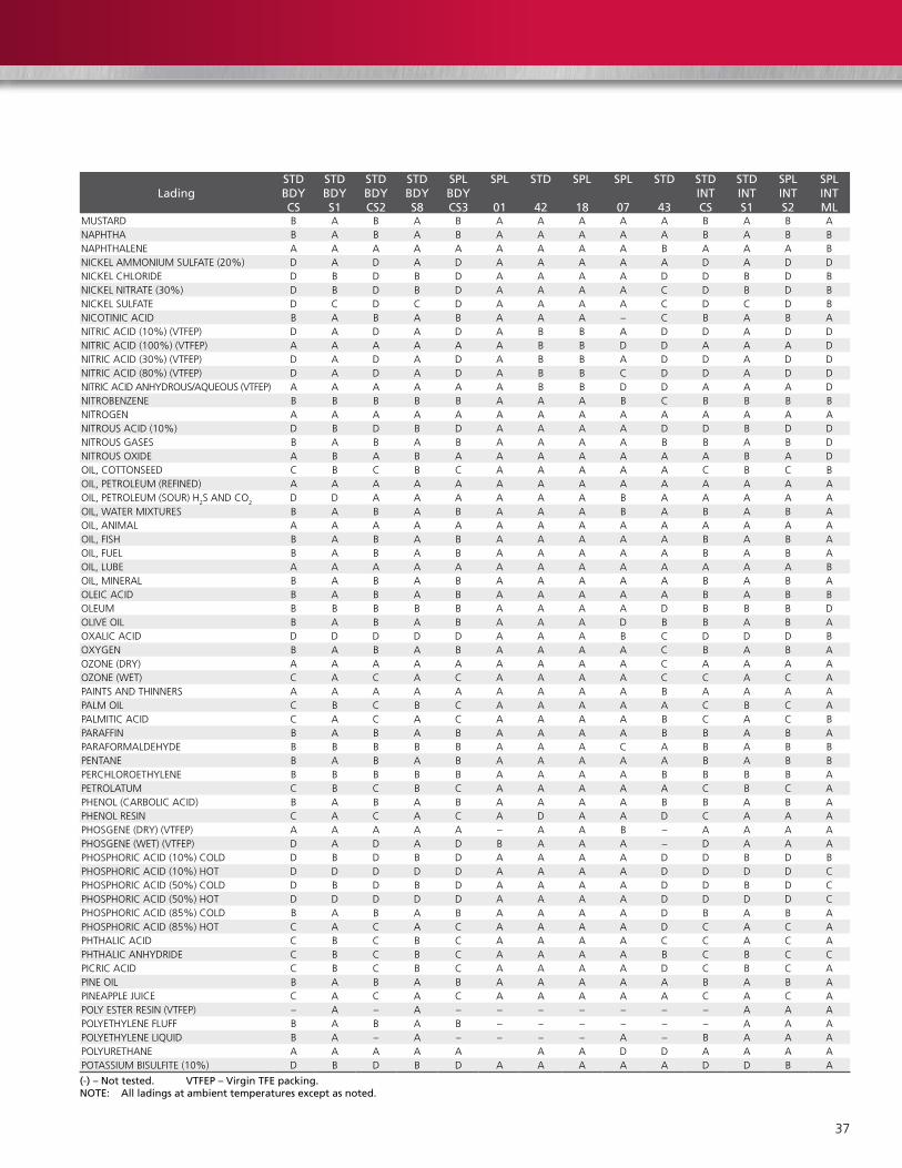
MateRIal SeleCtIon guIDe (ContInueD)
ladingStD BDy CS
StD BDy S1
StD BDy CS2
StD BDy S8
SPl BDy CS3
SPl
01
StD
42
SPl
18
SPl
07
StD
43
StD IntCS
StD IntS1
SPl IntS2
SPl IntMl
HYDROFLUORICACID D D D D D A C C D D D D D BHYDROFLUOSILICICACID D C D C D A A A A D D C D BHYDROGENGAS(COLD) B A B A B A A A B A B A B AHYDROGENPEROXIDE30%(DILUTE) D B D B D A A A B D D B D BHYDROGENPEROXIDE90% D B D B D A A A B D D D B DHYDROGENSULFIDE(DRY) D D A A A A A A A A D D A AHYDROGENSULFIDE(WET) D D B A B A B A A A D D A AHYPO(SODIUMTHIOSULFATE) D A D A D A A A A B D A D BHYPOCHLORITES,SODIUM D C D C D A A A A D D C D BILLUMINATINGGAS A A A A A A A A – A A A A AINK D A D A D A A A – A D A D BIODINE(WET) D D D D D A A A B B D D D DISO-OCTANE A A A A A A A A A A A A A AISODOFORM(DRY) B B B B B A A A – – B B B BSOPROPYLALCOHOL B B B B B A A A B B B B – BISOPROPYLETHER A A A A A A A A D C A A A AKEROSENE B A B A B A A A A A B A B AKETCHUP D A D A D A A A A A D A D BKETONES A A A A A A A A D A A A A ALACQUERS(SOLVENTS) C A C A C A A A D C C A C ALACTICACID(CONC.COLD) D A D A D A A A A B D B D DLACTICACID(CONC.HOT) D B D B D A A A A D D B D DLACTICACID(DILUTECOLD) D A D A D A A A A A D A D CLACTICACID(DILUTEHOT) D A D A D A A A A D D B D DLARDOIL C A C A C A A A A A C A C BLEADACETATE D B C B C A A A D C D B D BLINOLEICACID B A B A B A A A C C B A B BLINSEEDOIL A A A A A A A A A A A A A BLIQUEFIEDPETGAS(LPG) B A B A B A A A A A B A B BLITHIUMBROMIDE D A D A D D A A – – D A – ALUBRICATINGOIL A A A A A A A A A A A A A BMAGNESIUMBISULFATE(10%) C A C A C A A A A A C A C BMAGNESIUMCHLORIDE C D C D C A A A A C C D C BMAGNESIUMHYDROXIDE B A B A B A A A A A B A B AMAGNESIUMHYDROXIDE(HOT) B A B A B A A A B A B A B AMAGNESIUMSULFATE B B B B B A A A A C B B B BMALEICACID B C B C B A A A A C B C B BMALEICANHYDRIDE D A D A D – A A – – D A B AMALICACID D A D A D A A A A C D A D BMAYONNAISE D A D A D A A A A A D A D BMERCAPATANS A A A A A A A A A – A A A DMERCURICCHLORIDE D D D D D A A A A A D D D DMERCURICCYANIDE(10%) D B D B D A A A – B D B D DMERCURY A A A A A A A A A A A A A CMETHANE A A A A A A A A A A A A A AMETHYLACETATE A A A A A A A A D B A A A AMETHYLACETONE A A A A A A A A D C A A A AMETHYLCELLOSOLVE B B B B B A A A D B B B B BMETHYLCHLORIDE(DRY) B A B A B A A A A – B A B AMETHYLETHYLKETONE A A A A A A A A D A A A A AMETHYLFORMATE B B B B B A A A – B B B B BMETHYLAMINE B B B B B A A A – C B B B BMETHYLENECHLORIDE(DRY) B B B B B A A A B B B B B BMILK D A D A D A A A A A D A D AMINEWATERS(ACID) D B D B D A A A B C D B D BMINERALSPRITS B B B B B A A A A A B B B BMINERALOIL B A B A B A A A A A B A B AMIXEDACIDS(COLD) C A C A C A A A – D C A C BMOLASSES,CRUDE A A A A A A A A A A A A A AMOLASSES,EDIBLE A A A A A A A A A A A A A AMTBE100%MAX B A B A B A B A D B B A A AMTBE40%MAX A A A A A D A A D B – A A AMURIATICACID D D D D D A A A A D D D D B
(-) – not tested. VtFeP – Virgin tFe packing.note: all ladings at ambient temperatures except as noted.
37
ladingStD BDy CS
StD BDy S1
StD BDy CS2
StD BDy S8
SPl BDy CS3
SPl
01
StD
42
SPl
18
SPl
07
StD
43
StD IntCS
StD IntS1
SPl IntS2
SPl IntMl
MUSTARD B A B A B A A A A A B A B ANAPHTHA B A B A B A A A A A B A B BNAPHTHALENE A A A A A A A A A B A A A BNICKELAMMONIUMSULFATE(20%) D A D A D A A A A A D A D DNICKELCHLORIDE D B D B D A A A A D D B D BNICKELNITRATE(30%) D B D B D A A A A C D B D BNICKELSULFATE D C D C D A A A A C D C D BNICOTINICACID B A B A B A A A – C B A B ANITRICACID(10%)(VTFEP) D A D A D A B B A D D A D DNITRICACID(100%)(VTFEP) A A A A A A B B D D A A A DNITRICACID(30%)(VTFEP) D A D A D A B B A D D A D DNITRICACID(80%)(VTFEP) D A D A D A B B C D D A D DNITRICACIDANHYDROUS/AQUEOUS(VTFEP) A A A A A A B B D D A A A DNITROBENZENE B B B B B A A A B C B B B BNITROGEN A A A A A A A A A A A A A ANITROUSACID(10%) D B D B D A A A A D D B D DNITROUSGASES B A B A B A A A A B B A B DNITROUSOXIDE A B A B A A A A A A A B A DOIL,COTTONSEED C B C B C A A A A A C B C BOIL,PETROLEUM(REFINED) A A A A A A A A A A A A A AOIL,PETROLEUM(SOUR)H
2S ANDCO2 D D A A A A A A B A A A A AOIL,WATERMIXTURES B A B A B A A A B A B A B AOIL,ANIMAL A A A A A A A A A A A A A AOIL,FISH B A B A B A A A A A B A B AOIL,FUEL B A B A B A A A A A B A B AOIL,LUBE A A A A A A A A A A A A A BOIL,MINERAL B A B A B A A A A A B A B AOLEICACID B A B A B A A A A A B A B BOLEUM B B B B B A A A A D B B B DOLIVEOIL B A B A B A A A D B B A B AOXALICACID D D D D D A A A B C D D D BOXYGEN B A B A B A A A A C B A B AOZONE(DRY) A A A A A A A A A C A A A AOZONE(WET) C A C A C A A A A C C A C APAINTSANDTHINNERS A A A A A A A A A B A A A APALMOIL C B C B C A A A A A C B C APALMITICACID C A C A C A A A A B C A C BPARAFFIN B A B A B A A A A B B A B APARAFORMALDEHYDE B B B B B A A A C A B A B BPENTANE B A B A B A A A A A B A B BPERCHLOROETHYLENE B B B B B A A A A B B B B APETROLATUM C B C B C A A A A A C B C APHENOL(CARBOLICACID) B A B A B A A A A B B A B APHENOLRESIN C A C A C A D A A D C A A APHOSGENE(DRY)(VTFEP) A A A A A – A A B – A A A APHOSGENE (WET) (VTFEP) D A D A D B A A A – D A A APHOSPHORICACID(10%)COLD D B D B D A A A A D D B D BPHOSPHORICACID(10%)HOT D D D D D A A A A D D D D CPHOSPHORICACID(50%)COLD D B D B D A A A A D D B D CPHOSPHORICACID(50%)HOT D D D D D A A A A D D D D CPHOSPHORICACID(85%)COLD B A B A B A A A A D B A B APHOSPHORICACID(85%)HOT C A C A C A A A A D C A C APHTHALICACID C B C B C A A A A C C A C APHTHALICANHYDRIDE C B C B C A A A A B C B C CPICRICACID C B C B C A A A A D C B C APINEOIL B A B A B A A A A A B A B APINEAPPLEJUICE C A C A C A A A A A C A C APOLYESTERRESIN(VTFEP) – A – A – – – – – – – A A APOLYETHYLENEFLUFF B A B A B – – – – – – A A APOLYETHYLENELIQUID B A – A – – – – A – B A A APOLYURETHANE A A A A A A A D D A A A APOTASSIUMBISULFITE(10%) D B D B D A A A A A D D B A
(-) – not tested. VtFeP – Virgin tFe packing.note: all ladings at ambient temperatures except as noted.

38
MateRIal SeleCtIon guIDe (ContInueD)
ladingStD BDy CS
StD BDy S1
StD BDy CS2
StD BDy S8
SPl BDy CS3
SPl
01
StD
42
SPl
18
SPl
07
StD
43
StD IntCS
StD IntS1
SPl IntS2
SPl IntMl
POTASSIUMBROMIDE D B D B D A A A – A D B D BPOTASSIUMCARBONATE C A C A C A A A A A C A C BPOTASSIUMCHLORATE B A B A B A A A A A B A B BPOTASSIUMCHLORIDE C A C A C A A A A A C A C BPOTASSIUMCYANIDE B B B B B A A A A C B B B BPOTASSIUMDICHROMATE B A B A B A A A A C B A B BPOTASSIUMDIPHOSPHATE A A A A A A A A A A A A A BPOTASSIUMFERRICYANIDE B A B A B A A A A A B B B BPOTASSIUMFERROCYANIDE B A B A B A A A A A B A B APOTASSIUMHYDROXIDE70%(COLD) B B B B B A B B D C B B B APOTASSIUMHYDROXIDE70%(HOT) A A A A A A B B D C A A A APOTASSIUMHYDROXIDE-DILUTE(COLD) B B B B B A A A C A B B B APOTASSIUMHYDROXIDE-DILUTE(HOT) B A B A B A B B D B B B B APOTASSIUMIODIDE C B C B C A A A A A C B C APOTASSIUMNITRATE B A B A B A A A A A B A B APOTASSIUMPERMAGANATE A A A A A A A A A C A A A BPOTASSIUMSULFATE B A B A B A A A A C B A B BPOTASSIUMSULFIDE(10%) C B C B C A A A A A C B C DPOTASSIUMSULFITE(10%) D A D A D A A A A A D A D DPRODUCERGAS B A B A B A A A A A B A B APROPANE A A A A A A A A A A A A A APROPLENE – A – A – – – – A – – A A APROPYLALCOHOL A A A A A A A A A A A A A APROPYLENEGYLCOL A A A A A A A A A A A A A APYROGALLICACID B B B B B A A A D B B B BQUENCHOIL(WATERSOLUBLE) A A A A A A A A B B A A A –RESINS-ROSINS C A C A C A A A B C A C AROAD TAR A A A A A A A A A B A A A AROOFPITCH A A A A A A A A A B A A A ARUBBERLATEXEMULSIONS B A B A B A A A A A B A B –RUBBERSOLVENT A A A A A A A A D B A A A ASALADOIL C B C B C A A A A A C B C BSALICYLICACID D A D A D A A A A B D A D ASALT C B C B C A A A A A C B C ASEAWATER D A D A D A A A A A D A D ASHELLAC(BLEACHED) A A A A A A A A D B A A A ASHELLAC(ORANGE) A A A A A A A A D B A A A ASILICONEOILS A A A A A A A A A A A A A ASILVERNITRATE D B D B D A A A A B D B D DSOAPSOLUTIONS(STEARATES) A A A A A A A A A A A A A ASODIUMACETATE B B B B B A A A D B B B B BSODIUMALUMINATE C A C A C A A A A A C A C ASODIUMBICARBONATE C B C B C A A A A A C B C BSODIUMBISULFATE(10%) D A D A D A A A A A D A D BSODIUMBISULFITE(10%) D D D D D A A A A A D D D BSODIUMBORATE C D C D C A A A A A C D C BSODIUMBROMIDE(10%) C B C B C A A A A A C B C BSODIUMCARBONATE B B B B B A A A A A B B B ASODIUMCHLORATE C B C B C A A A A A C B C BSODIUMCHLORIDE C B C B C A A A A A C B C ASODIUMCHROMATE B B B B B A A A A D B B B BSODIUMCYANIDE(10%) A A A A A A A A A B A A A BSODIUMFLUORIDE D B D B D A A A A A D B D ASODIUMHYDROXIDE20%(COLD) A A A A A A A A B A A A A ASODIUMHYDROXIDE20%(HOT) C B C B C A B B C B C B C ASODIUMHYDROXIDE50%(COLD) B B B B B A C C C A B B B ASODIUMHYDROXIDE50%(HOT) B B B B B A C C C B B B B ASODIUMHYDROXIDE70%(COLD) C B C B C A C C C C C B C BSODIUMHYDROXIDE70%(HOT) B B B B B A D D C C B B B BSODIUMHYPOCHLORIDE D D D D D A A A A D D D D DSODIUMMETAPHOSPHATE A B A B A A A A A A A B A BSODIUMMETASILICATE(HOT) D A D A D A A A – A D A D A(-) – not tested. VtFeP – Virgin tFe packing.note: all ladings at ambient temperatures except as noted.

39
(-) – not tested. VtFeP – Virgin tFe packing.note: all ladings at ambient temperatures except as noted.
ladingStD BDy CS
StD BDy S1
StD BDy CS2
StD BDy S8
SPl BDy CS3
SPl
01
StD
42
SPl
18
SPl
07
StD
43
StD IntCS
StD IntS1
SPl IntS2
SPl IntMl
SODIUMMETASILICATE(COLD) C A C A C A A A – A C A C ASODIUMNITRATE B B B B B A A A – C B B B BSODIUMPERBORATE B B B B B A A A A A B B B BSODIUMPEROXIDE C B C B C A A A A B C B C BSODIUMPHOSPHATE(DIBASIC) B B B B B A A A A A B B B BSODIUMPHOSPHATE(TRIBASIC) B B B B B A A A A A B B B BSODIUMSILICATE A A A A A A A A A A A A A BSODIUMSILICATE(HOT) B B B B B A A A A A B B B BSODIUMSULFATENA2S04 B A B A B A A A A A B A B ASODIUMSULFIDE(HOT) C B C B C A A A A A C B C BSODIUMSULFIDENA2S02 B B B B B A A A A A B B B ASODIUMTHIOSULFATE D B D B D A A A A A D B D BSOURGASANDOIL D D A A A A A A A A D D A ASOYBEANOIL C A C A C A A A A A C A C ASTANNICCHLORIDE D D D D D A A A A B D D D CSTANNOUSCHLORIDE D C D C D A A A A D D C D CSTARCH A A A A A A A A A A A A A ASTEAM(212°F) B A B A B B C A D D B A A ASTEARICACID C A C A C A A A B C A C BSTODDARD SOLVENT B B B B B A A A A A B B B BSTYRENE A A A A A B D D D B A A A ASUGARLIQUIDS B A B A B A A A A A B A B ASULFATE,BLACKLIQUORS C B C B C A A A B B C B C BSULFATE,GREENLIQUORS C B C B C A A A A B C B C BSULFATE,WHITELIQUORS D B D B D A A A A B D B D BSULFURICACID(0to7%)(VTFEP) D B D B D A A A A D D B D BSULFURICACID(100%)H2S04 (VTFEP) B B B B B A A A B D B B B DSULFURICACID(20%)(VTFEP) D D D D D A A A A D D D D BSULFURICACID(50%)(VTFEP) D D D D D A A A A D D D D BSULFUROUSACID D D D D D A A A A D D D D DSULPHUR B A B A B A A A A C B A B ASULPHURDIOXIDE(DRY) B A B A B A A A A A B A B ASULPHURTRIOXIDE(DRY) B B B B B A A A A B B B B BSYNTHESISGAS B B B B B A A A A A B B B ATALLOIL B B B B B A A A A A B B B ATANNICACID B B B B B A A A A A B B B BTAR–TAROIL A A A A A A A A A B A A A ATARTARICACID D B D B D A A A A B D B D BTETRAETHYLLEAD C B C B C A A A A B C B C ATITANIUMTETRACHLORIDET1-CL4 – – – – – – – A – – – – – –TITANIUMTRICHLORIDET1-CL3 – – – – – – – A – – – – – –TOLUENE–TOLUOL A A A A A A A A A B A A A ATOMATOJUICE C A C A C A A A A A C A C ATRANSFORMEROIL A A A A A A A A A A A A A ATRIBUTYLPHOSPHATE A A A A A A A A D B A A A ATRICHLOROETHYLENE B B B B B A A A B B B B B ATUNGOIL B A B A B A A A A A B A B CTURPENTINE B A B A B A A A A A B A B BUREA C B C B C A A A – – C B C AVARNISH C A C A C A A A B B C A C AVEGETABLEOIL,EDIBLE B A B A B A A A A A B A B BVEGETABLEOIL,NON-EDIBLE B A B A B A A A A A B A B BVINEGAR D A D A D A A A A A D A D AWATER,DISTILLED(AREATED) D A D A D A A A A A D A D AWATER, FRESH C A C A C A A A A A C A C AWATER, SEA D A D A D A A A A A D A D AWAX,EMULSIONS A A A A A A A A A A A A A –WAXES A A A A A A A A A A A A A AWHISKEYANDWINE D A D A D A A A A A D A D AXYLENE(DRY) A A A A A A A A A A A A A AZINCCHLORIDE D D D D D A A A A C D D D BZINCHYDROSULFITE A A A A A A A A A D A A A BZINCSULFATE D B D B D A A A A D D B D B

40
CaMSeRV™ Services for Valves and actuation
global network and local Support
Cameroniswell-positionedtodelivertotalaftermarket
support,quicklyandefficiently,withunmatchedOEM
expertise.Ourhighlyskilledengineersandtechniciansare
availablearoundtheclock,sevendaysaweektorespond
tocustomerqueries,troubleshootproblemsandoffer
reliablesolutions.
easily accessible Parts and Spare Valves
• OEMsparevalves,actuatorsandparts(includingnon-Cameronbrands)
• Handling,storage,packaginganddelivery
• Dedicatedstockingprogram
Comprehensive aftermarket Services Portfolio
• Partsandsparevalves
• Repair
• Fieldservices
• Preventativemaintenance
• Equipmenttestinganddiagnostics
• Remanufacturing
• Assetpreservation
• Customerpropertymanagement
• Trainingandrecertificationservices
• Warranty
Customized total Valve CareSM
(tVC) Programs
Customizedassetmanagementplansthatoptimize
uptime,availabilityanddedicatedservices.
• Engineeringconsultancy
• Sitemanagement
• Flangemanagement
• Startupandcommissioning
• Sparepartsandassetmanagement
• Operationalsupport
We BuIlD It. We BaCK It.
USA • CANADA • LATIN AMERICA • EUROPE • RUSSIA • AFRICA • MIDDLE EAST • ASIA PACIFIC

41
trademark Information
WKMisaregisteredtrademarkofCameron.CAMSERVandDynaSealaretrademarksofCameron.
Thisdocumentcontainsreferencestoregisteredtrademarksorproductdesignations
thatarenotownedbyCameron.
trademark owner Common name Comparable Cameron
abbreviated name (in trim charts)
Celcon Hoechst Celanese Corporation
teflon e.I. DuPont De nemours & Company Poly tetra Fluoro ethylene PtFe
Viton DuPont Dow elastomers l.l.C. Fluoroelastomer FKM
17-4PH armco advanced Materials Corp. 17-4PH Stainless Steel type 630
electroless nickel Plating enP

©2013 Cameron | WKM is a registered trademark of Cameron. CaMSeRV and DynaSeal are trademarks of Cameron. total Valve Care is a service mark of Cameron. | SWP 1.5M 12/13 aD01110V
3250 Briarpark Drive, Suite 300
Houston, tX 77042
uSa
toll Free 1.800.323.9160
learn more about WKM at:
www.c-a-m.com/valves
HSE Policy Statementat Cameron, we are committed ethically, financially and personally to a working environment where no one gets hurt and nothing gets harmed.
HEALT
H S
AFE
TY A
ND ENVIRONMENTAL EX
CELLEN
CE
CAMERON