
WIYN’s Role in the US System of Telescopes
32
1 WIYN’s Role in the US System of Telescopes WIYN 3.5-m 0.9-m (36-inch)
Transcript of WIYN’s Role in the US System of Telescopes

1
WIYN’s Role in the US System of Telescopes
WIYN 3.5-m
0.9-m(36-inch)

2
The WIYN 3.5-m Telescope
• Alt-Az telescope mount
• Active optics corrects for mirror flexure (15-30s updates)
• Wide Field capability (1º unvignetted) at two Nasmyth ports
• Native seeing ~0.7” in R-band
• Slow f-ratio (6.3), well-suited to narrowband science
• Three available ports: 2 Nasmyth & one Cass port can have four instruments “hot” (usually 3 are available)
W – University of Wisconsin (26%)I – Indiana University (17%)Y – Yale University (17%)N – NOAO (40%)

3
WIYN’s Capabilities – Well Suited For Programs Needing …
• Good image quality• 1º field of view• Remote observing
♦ Broad student participation♦ Short runs, split nights ♦ Multiple observers per night♦ Rapid schedule changes
• Multiple instruments♦ To change program with conditions♦ Various observing modes possible,
but not currently supported• Queue• Target of Opportunity• Synoptic

4
Current Instruments• MiniMosaic (4Kx4K) imager (10’ field)• OPTIC (4Kx4K) imager with OT CCDs [50% loan from J. Tonry]• WTTM (2Kx2K) tip/tilt corrected imager [always on]B Hydra fiber positioner (~85 fibers, 2” and 3” sets)[dedicated port]B Densepak – 7x13 fiber bundle (3” fibers; closely spaced)B Sparsepak – 82 fibers (5” fibers; great for LSB objects)
Densepak Sparsepak
5
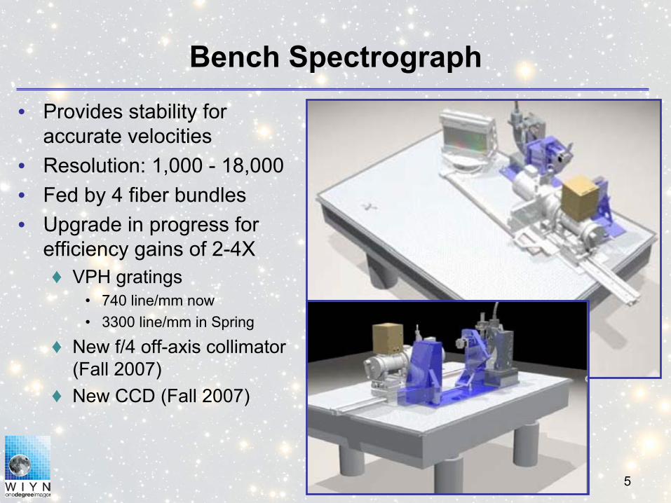
Bench Spectrograph• Provides stability for
accurate velocities• Resolution: 1,000 - 18,000• Fed by 4 fiber bundles• Upgrade in progress for
efficiency gains of 2-4X♦ VPH gratings
• 740 line/mm now• 3300 line/mm in Spring
♦ New f/4 off-axis collimator (Fall 2007)
♦ New CCD (Fall 2007)

6
Under Development• QUOTA – NSF/ATI and WIYN funded (about 50% - 50%)
♦ 8K x 8K imager with 4 OT sensors (“OTAs”, more later)♦ 0.11” pixels♦ 16 arcmin FOV♦ Commissioning began October 2006
• WHIRC – WIYN HIgh Resolution infraRed CameraFunded by STScI, NSF/ATI (led by Margaret Meixner, STScI), & WIYN
♦ 2K x 2K Near-infrared imager for WIYN Tip/Tilt adapter♦ 0.1” pixels for near-diffraction limited imaging (3’ FOV)♦ 13 Filters, including narrow-band, 3 redshifted♦ Expected delivery – mid 2007
• One Degree Imager – Funding from WIYN (75%) & NSF/TSIP (25%)♦ 32K x 32K imager with OTAs♦ ODI Details to follow♦ Expected delivery – mid 2009

7
One Degree Imager Overview

8
Sample Science Drivers for ODI
• Galaxy Evolution: Galaxies resolve if seeing better than 0.4’’• Resolved Stellar Populations: Deep photometry under
excellent seeing condition (RR Lyr in Local Group Galaxies)• Astrometry: Proper motion of stars, Kuiper Belt Objects,
parallaxes to 1 kpc• Large field of view for surveys: from Galactic structure to
galaxy evolution at high z• Good image quality improves weak lensing detection• Fast readout (8s) to study the variable sky• High-Speed Photometry (to 40 Hz): Flickering stars;
accretion disks in Galactic & AGN sources to 50 millisecond timescale; planet transits
9
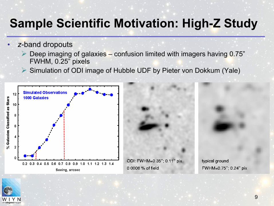
Sample Scientific Motivation: High-Z Study• z-band dropouts
Deep imaging of galaxies – confusion limited with imagers having 0.75” FWHM, 0.25” pixelsSimulation of ODI image of Hubble UDF by Pieter von Dokkum (Yale)
10
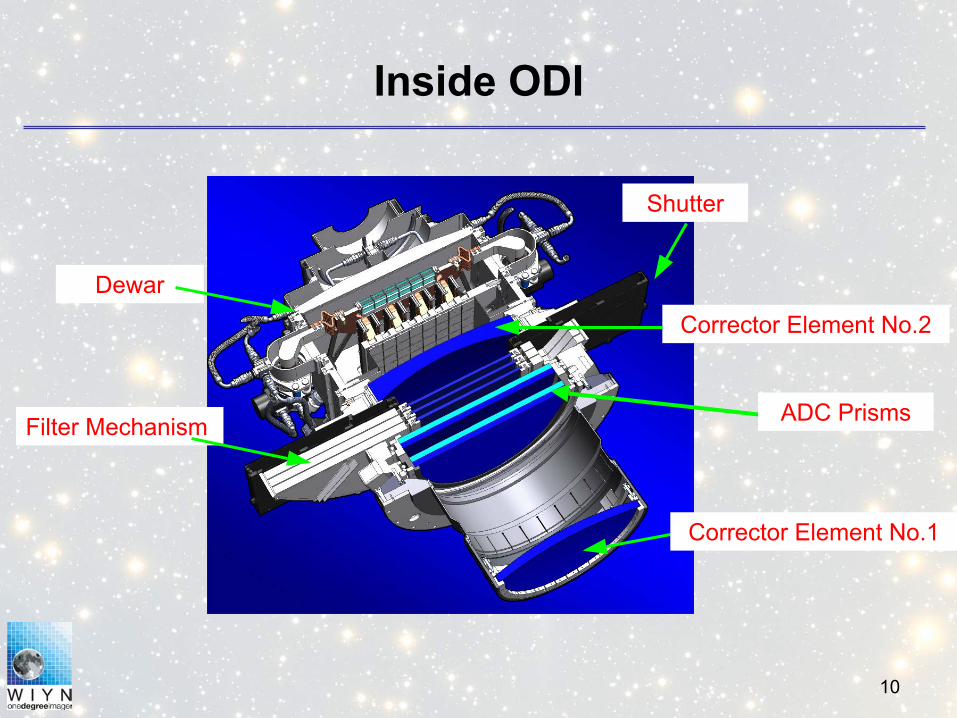
Inside ODI
ADC Prisms
Dewar
Filter Mechanism
Shutter
Corrector Element No.1
Corrector Element No.2
11
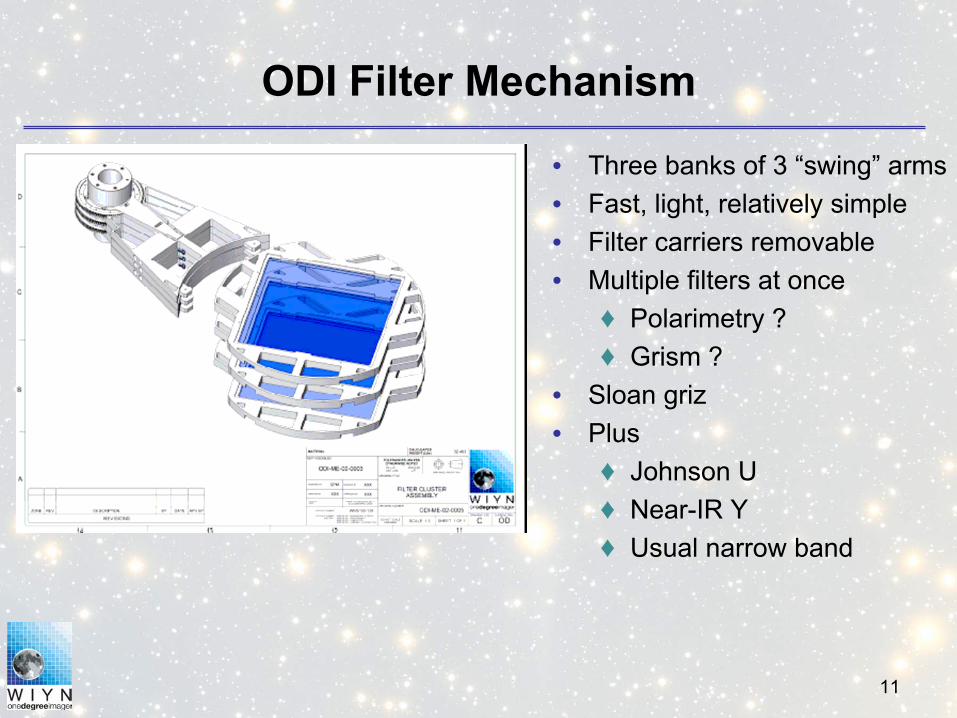
ODI Filter Mechanism
• Three banks of 3 “swing” arms• Fast, light, relatively simple• Filter carriers removable• Multiple filters at once
♦ Polarimetry ?♦ Grism ?
• Sloan griz• Plus
♦ Johnson U♦ Near-IR Y♦ Usual narrow band
12
ODI’s place in the Astronomical Landscape
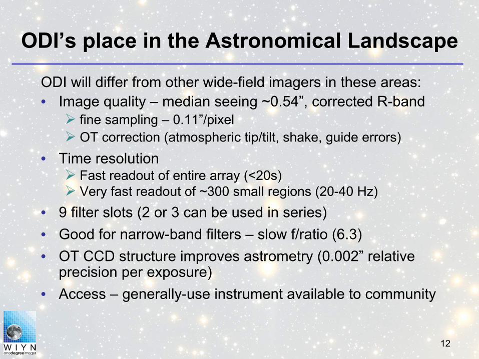
ODI will differ from other wide-field imagers in these areas:• Image quality – median seeing ~0.54”, corrected R-band
fine sampling – 0.11”/pixelOT correction (atmospheric tip/tilt, shake, guide errors)
• Time resolutionFast readout of entire array (<20s)Very fast readout of ~300 small regions (20-40 Hz)
• 9 filter slots (2 or 3 can be used in series)• Good for narrow-band filters – slow f/ratio (6.3)• OT CCD structure improves astrometry (0.002” relative
precision per exposure)• Access – generally-use instrument available to community

13
The Orthogonal Transfer CCD and Array
• Pixel is broken into 2 triangles with extra gate• Allows charge to clock up/down or left/right
14
QUOTA - the ODI Demo Camera
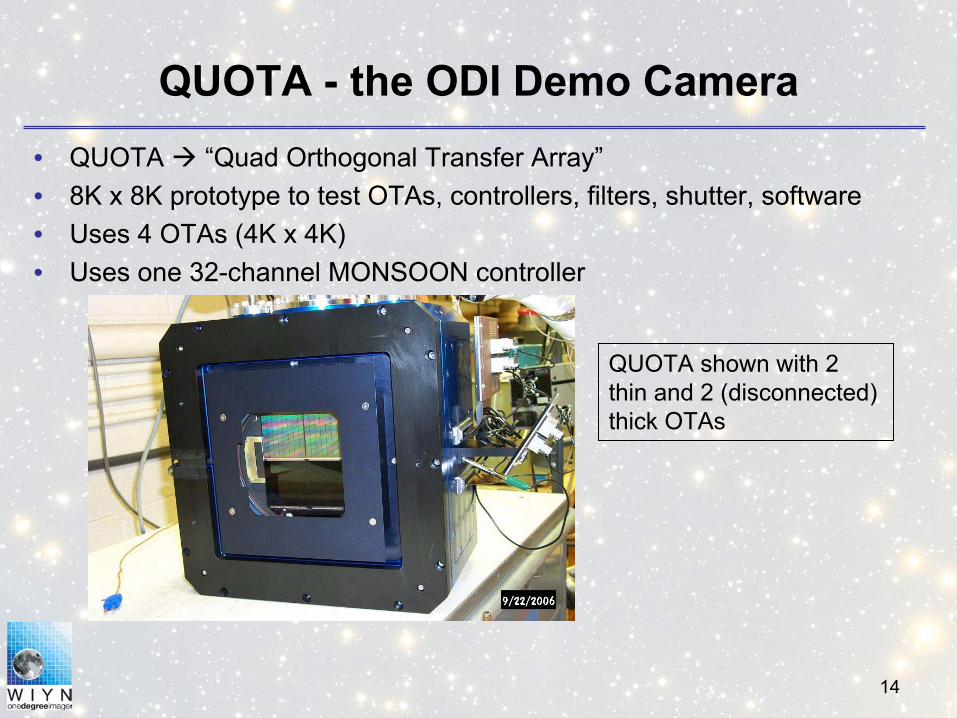
QUOTA shown with 2 thin and 2 (disconnected) thick OTAs
• QUOTA “Quad Orthogonal Transfer Array”• 8K x 8K prototype to test OTAs, controllers, filters, shutter, software• Uses 4 OTAs (4K x 4K)• Uses one 32-channel MONSOON controller
15
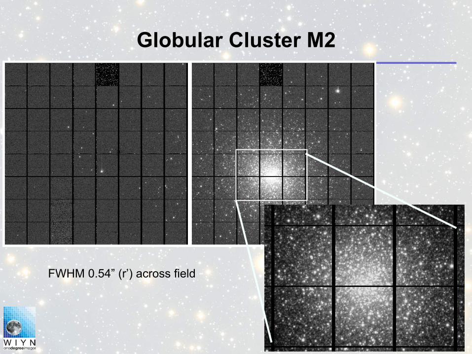
Globular Cluster M2
FWHM 0.54” (r’) across field

16
M76 in Hα (0.6” FWHM)
1.3”

17
TSIP Return to Community• ODI is funded at ~25% through TSIP• WIYN will provide:
♦ 40 nights from the non-NOAO 60% share (7 nts per semester starting Fall 2009)
♦ Invitation to participate in a 90-night survey carried out by Yale♦ All ODI data will be made public after 18 month proprietary period
• Yale 3-year survey strawman strategy♦ Targeting stellar parallaxes, high redshift galaxies, SNe, variables♦ 3h every 4th night using z’ and Y filters in groups of 4 months♦ 3 deep field and 90 shallow fields (over a year) to:
• z’ ~ 27.5 (deep); z’ ~ 26.0 (wide)• Y depends on detector performance
♦ Opportunity for community to refine plan, add time
18
• John Cavin, Project Manager• Charles Corson, Telescope Engineer• Daniel Harbeck, Project Scientist• Charles Harmer, Optical Designer• Steve Howell, Telescope Scientist• George Jacoby, ODI optics, QUOTA• Joe Keyes, Mechanical Engineer• Pat Knezek, Design Review Coordinator• Gene McDougall, Electronics Engineer• Gary Muller, Mechanical Engineer• Dave Sawyer, Project Engineer• Andrey Yeatts, Software Engineer• NOAO engineering, Monsoon
ODI Team
19
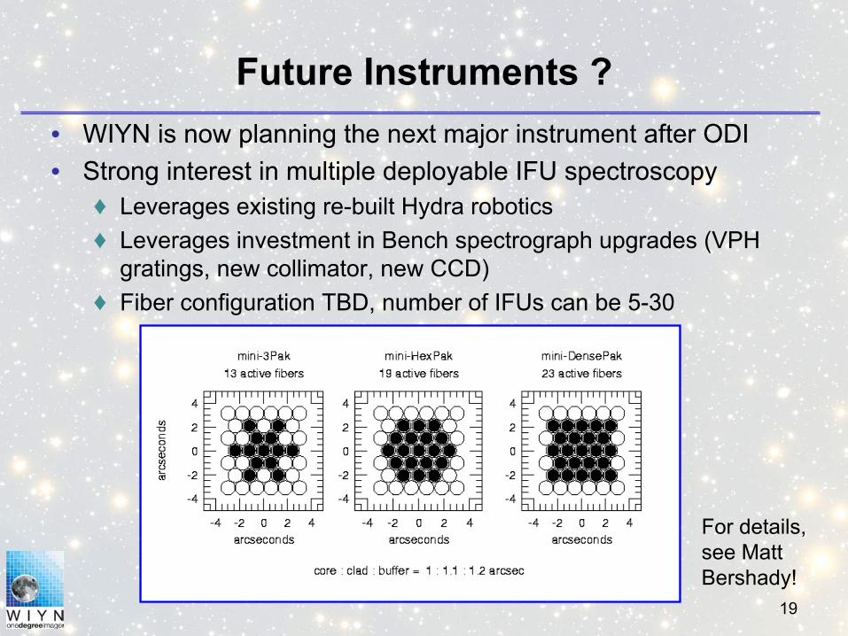
Future Instruments ?• WIYN is now planning the next major instrument after ODI• Strong interest in multiple deployable IFU spectroscopy
♦ Leverages existing re-built Hydra robotics♦ Leverages investment in Bench spectrograph upgrades (VPH
gratings, new collimator, new CCD)♦ Fiber configuration TBD, number of IFUs can be 5-30
For details, see Matt Bershady!

20
Spatial Heterodyne Spectroscopy (SHS)
• Compact spectrometer for ELTs –concept to be tested at WIYN.
• Wavelength dependent Fizeaufringes which result from crossed wavefronts 1 and 2 at the exit of the interferometer are recorded along the x-direction by a detector array.
• The Fourier transform of the fringe pattern returns the spectrum.
• See Andy Sheinis!
21
WIYN 0.9-m Telescope
• Formerly, operated by KPNO• WIYN renovated in 2001• Heavily used for students, outreach• ~20% of time is available through NOAO• Instruments
♦ Kitt Peak Mosaic (8K x 8K) – One Degree FOV (0.4” pixels)♦ 2K x 2K SITe CCD (21 arcmin FOV, 0.68” pixels)
• Future – “Half Degree Imager” ♦ 4K x 4K Monolithic imager (0.4” pixels)♦ Funded by PREST

22
PREST Return to Community (5 years)
• 20% access to HDI• Access to all HDI data after proprietary period• Access to 0.9m queue opportunities
♦ 1-2 hours per night for synoptic targets♦ “Opportunity” queue (“Let’s make a deal” with whoever is
observing) – See: http://www.noao.edu/0.9m/oq/• Web posting of desired observation and proposed reward!• Rewards like co-authorship are more attractive than acknowledgements• Short blocks of time are more likely to be chosen than large blocks• Standard (UBVRI) filters impact calibration plans less than special filters• Moonlit conditions are more attractive than dark conditions• Interesting and complete descriptions of the science may be more inspiring• Friendly, prompt and helpful correspondence with observers fosters better
observations.

23

24
WHIRC Details
Raytheon Virgo/Vista science grade arraySelected IR array
$200K (includes MUX for testing)Array cost
~3.4’x3.4’Field of view
Raytheon (2K2 with 20 µm pixels)Focal plane
0.1”/pixelPlate scale
13 filters (J, H, Ks, numerous narrowband, eg. Brγ, HeI, H2, CO, some redshifted)Filters
80%,91%,90%Estimated QE (JHKs)
0.8 – 2.5 µmWavelength range

25
WHIRC Filter Set (13)
2.12H2
1.061Low airglow 2.1924Br γ +4500 km/s1.6710[Fe II] +4500 km/s1.3032Pa β +4500 km/s2.295CO2.16Br γ1.6463[Fe II]1.2840Pa β1.083He I2.15Ks1.635H1.25J
µmWavelengthFilter

26
OTAs: Orthogonal Transfer Arrays
• 64 independent 480x494 CCDs• Individual addressing of CCDs• 1 arcmin field of view at WIYN• Bad columns confined to cells• Point defects are tolerated
• Cells with bright stars guide stars, or read fast, up to 40 Hz, to avoid blooming, or for time studies
• 8 video channels – 8s readout
• Intercell gaps (0.1-0.3 mm; 1-3”);
• Inter-OTA spacings: ~1 mm (10”)
50mm
12 µm pixels = 0.11” at WIYN
27
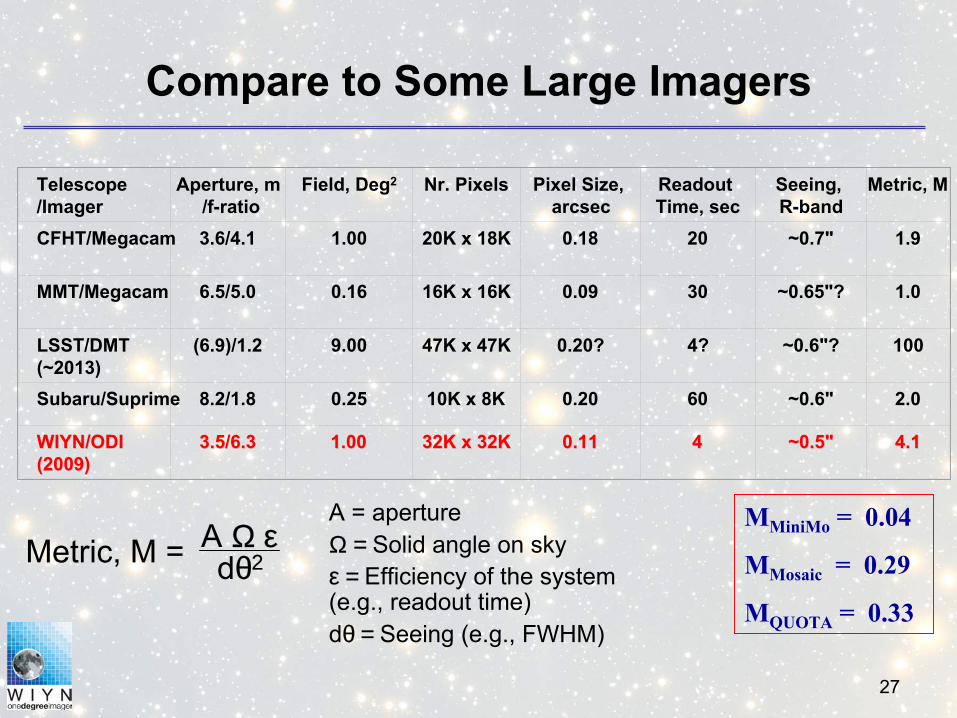
Compare to Some Large Imagers
Telescope/Imager
Aperture, m/f-ratio
Field, Deg2 Nr. Pixels Pixel Size, arcsec
Readout Time, sec
Seeing, R-band
Metric, M
CFHT/Megacam 3.6/4.1 1.00 20K x 18K 0.18 20 ~0.7" 1.9
MMT/Megacam 6.5/5.0 0.16 16K x 16K 0.09 30 ~0.65"? 1.0
LSST/DMT(~2013)
(6.9)/1.2 9.00 47K x 47K 0.20? 4? ~0.6"? 100
Subaru/Suprime 8.2/1.8 0.25 10K x 8K 0.20 60 ~0.6" 2.0
WIYN/ODIWIYN/ODI(2009)(2009)
3.5/6.33.5/6.3 1.001.00 32K x 32K32K x 32K 0.110.11 44 ~0.5"~0.5" 4.14.1
Metric, M = A Ω εdθ2
MMiniMo = 0.04
MMosaic = 0.29
MQUOTA = 0.33
A = aperture Ω = Solid angle on skyε = Efficiency of the system (e.g., readout time)dθ = Seeing (e.g., FWHM)
28
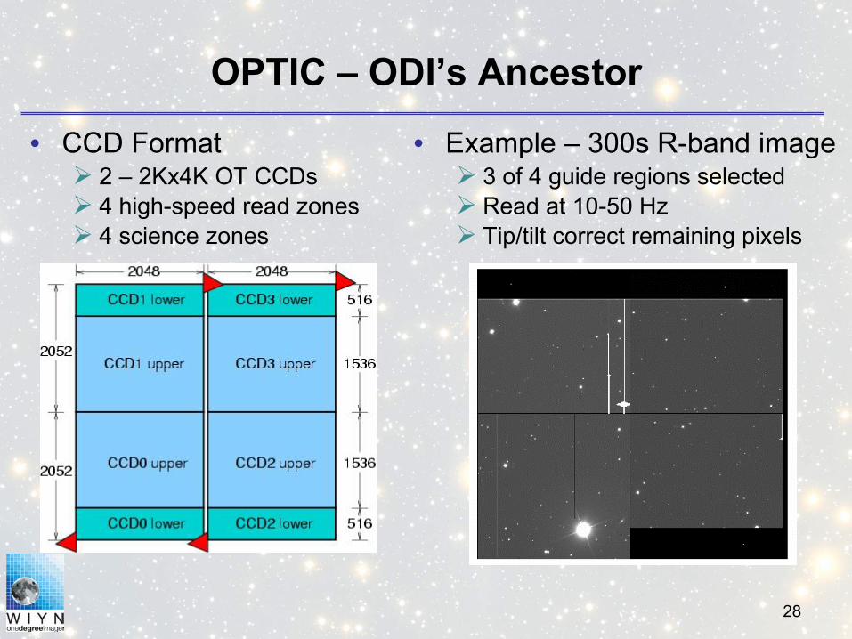
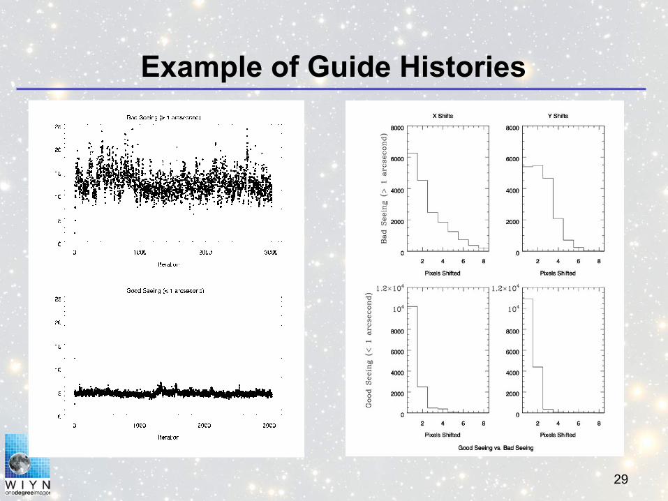
OPTIC – ODI’s Ancestor
• Example – 300s R-band image3 of 4 guide regions selectedRead at 10-50 HzTip/tilt correct remaining pixels
• CCD Format2 – 2Kx4K OT CCDs4 high-speed read zones4 science zones
29
Example of Guide Histories
30
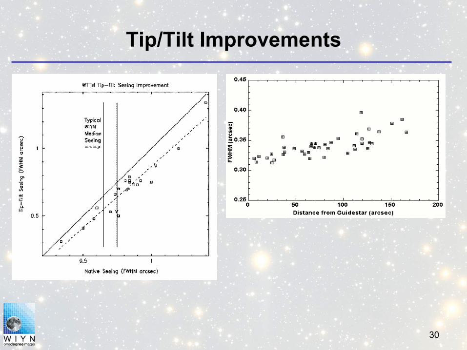
Tip/Tilt Improvements

31
Quantum Efficiency• Quantum Efficiency (QE) has not been evaluated yet. The
backside processing for OTAs is no different than conventional CCDs, so it is expected to be similar to other thinned devices such as FAME (plot below).
• The QE will be evaluated with one of the thinned devices expected this week (August 24).

32
Need for Atmospheric Dispersion Compensator
HDF South 0.8” simulated seeing
0.4” simulated seeingODI goal
0.4” simulated seeingw/o ADC at X=1.3, g’ band