With Out Details-file2
83
INDEX CHAPTER 1 INTRODUCTIO N…………………………………………………….2 Introduction to Routin g………………………………………………………………..2 Metrics……………………………………………………………………………3 Routing Protoco l………………………………………………………………….4 CHAPTER 2 LITERATURE REVIE W……………………………………………..6 Importance of Routing Protocol s…………………………………………………6 Characteristics of Routing Protocol s……………………………………………...6 Classification of Routing Protocol s……………………………………………….7 Interior Gateway Protocols (IGP )……………………………………………..7 Exterior Gateway Protocols (EGP )....................2 1 CHAPTER 3 SYSTEM FLOWCHART AND LOGICAL DIAGRAM S...........2 8 CHAPTER 4 RESULTS AND DISCUSSION S.......................2 9 Simulation...........................................2 9 Simulator............................................ 2 9 Structure of the OPNE T................................2 9 Simulation Stud y......................................3 0 Results.............................................. 3 0 CHAPTER 5 SCOPE OF THE WOR K.............................3 9 CHAPTER 6 CONCLUSIO N...................................40 CHAPTER 7 BIBLIOGRAPH Y.................................41
-
Upload
prabh-jeet -
Category
Documents
-
view
230 -
download
0
Transcript of With Out Details-file2

INDEX
CHAPTER 1 INTRODUCTION…………………………………………………….2 Introduction to Routing………………………………………………………………..2
Metrics……………………………………………………………………………3
Routing Protocol………………………………………………………………….4
CHAPTER 2 LITERATURE REVIEW……………………………………………..6
Importance of Routing Protocols…………………………………………………6
Characteristics of Routing Protocols……………………………………………...6
Classification of Routing Protocols……………………………………………….7
Interior Gateway Protocols (IGP)……………………………………………..7 Exterior Gateway Protocols (EGP)...................................................................21
CHAPTER 3 SYSTEM FLOWCHART AND LOGICAL DIAGRAMS....................28
CHAPTER 4 RESULTS AND DISCUSSIONS..........................................................29
Simulation..............................................................................................................29
Simulator...............................................................................................................29
Structure of the OPNET........................................................................................29
Simulation Study....................................................................................................30
Results...................................................................................................................30
CHAPTER 5 SCOPE OF THE WORK.....................................................................39
CHAPTER 6 CONCLUSION....................................................................................40
CHAPTER 7 BIBLIOGRAPHY................................................................................41

LIST OF FIGURES
Figure 1: Classification of Routing Protocols………………………………………7
Figure 2: OSPF Packet Header…………………………………………………….10
Figure3: BGP Message Header Format……………………………………………24
Figure4: Steps to develop and analyze protocols…………………………………..28
Figure5: Topology considered for OSPF…………………………………………. 30
Figure6: OSPF protocol showing the traffic sent………………………………….31
Figure7: OSPF protocol showing the traffic received……………………………..31
Figure8: showing the shortest path followed by OSPF……………………………31
Figure9: showing the shortest path followed by OSPF………………. …………..31
Figure10: Network considered for IGRP…………………………………………..32
Figure11: Topology considered inside IGRP network…………………………….32
Figure12: IGRP protocol showing the traffic sent ………………………………...32
Figure13: IGRP protocol showing the traffic sent ………………………………...32
Figure14: IGRP protocol showing traffic sent v/s received……………………….33
Figure15: Network considered for EIGRP………………………………………...33
Figure16: Topology considered inside EIGRP network…………………………..33
Figure17: EIGRP protocol showing the traffic sent……………………………… 34
Figure18: EIGRP protocol showing the traffic sent……………………………….34
Figure19: EIGRP showing traffic sent v/s traffic received………………………..34
Figure20: Topology considered for BGP………………………………………….35
Figure21: BGP protocol showing traffic sent……………………………………. 35

Figure22: BGP protocol showing traffic received…………………………………35
Figure23: BGP protocol showing traffic sent v/s received………………………...36
Figure24: Simulation information of IGRP and EIGRP…………………………...37
Figure25: Simulation result of EIGRP……………………………………………..37
Figure26: Simulation result of IGRP…………………………………………………...37
Figure27: Comparison between IGRP and EIGRP………………………………...38

CHAPTER 1 INTRODUCTION
This project aims to implement protocols depending on their topology in the network.
Protocols considered in this project are IGRP, EIGRP, OSPF and BGP. The protocols
are compared by executing simulation on various scenarios using OPNET simulator.
Introduction to Routing
Routing can be defined as selecting a path in a network over which we can send
some network traffic. Routing is used for various types of networks like circuit
switch network, or packet switch network. Here we are discussing about routing that
is used to route packets over a network which uses the packet switch technology.
When sing packet switch networks, the packets are forwarded from the sender side to
the receiver side using various intermediate nodes. These packets are provided the
logical addresses of the destination. There are various intermediate nodes like
routers, switches, gateways, hub, bridges, etc. In routing, various packets are
forwarded based on the routing tables that are maintained in each router memory to
record the different destinations present in the network. These tables are present in
the router’s memory and play an important role to provide effective routing. There
are different types of algorithms available that are used for routing. Most of the
algorithms use single path but some also use multipath routing. Multipath routing is
done through multiple alternative paths.
When there is an overlapping or an equal route, the following elements are taken into account so as to decide which route will be put in the routing table (priorities of the elements are checked):
1. Administrative distance: Routes that have less distance is preferred.
2. Prefix-Length: Routes with longer subnet masks preferred.
3. Metric: Routes having the lowest metric/cost will be preferred.
The goal of routing is to select a best path from the source node using minimal number of intermediary nodes to deliver the data packets to the destination nodes. Routing is done by the Network layer.
2

Two types of Routing approaches are defined below.
1. Connectionless mode: The path finding algorithm is executed every time a packet needs to be delivered.
2. Connection oriented mode: A path is set up once from the source node to the destination node before a data transmission begins.
Different modes of communication are used.
1. Unicast: One sender node send information to one receiver node.
2. Multicast: One sender node sends the information to a group of receiver nodes simultaneously.
3. Broadcast: One sender node sends the information to all the receiver nodes over the network.
Metrics
The measurement of path cost usually depends on the metric parameters. Metrics are used in a routing protocol to decide which path to use to transmit a packet through an internetwork.
Routing protocols consider various metric parameters to decide an appropriate path to
route a packet over a network. The path cost is estimated for each route when multiple
paths are present for the same destination and the best one i.e. smallest, is chosen.
Different routing protocols use different metric parameters to choose a route to rank them with priorities. The various metric parameters are discussed below:
1. Hop Count: It is the number of hops (routers) a packet travels through to reach the destination.
2. Bandwidth: The bandwidth speed is measured for the paths and the one having the highest bandwidth speed is chosen.
3. Delay: Delay is the time taken by the packets to get through the path. There are various factors on which Delay depends like the distance travelled, the link bandwidth, the port queues present in the network, etc.
3

4. Cost: A cost of the path is estimated to get the best route. A single metric or a combination of metrics can be used to estimate the cost.
5. Load: It is the traffic utilization of a path. Load is used to get the best path by the routing protocol.
6. Reliability: The reliability of the path is measured from failures and interface error count.
Routing Protocol
A routing protocol is used to deliver the packets from the sender node to the receiver
node via different intermediary nodes if required over a network. The intermediary
routes. A routing protocol describe the communication of the routers with each other
and enable them to choose a route over a network. Routing algorithms determine the
specific choice of route. Each router has a priori knowledge only of networks
attached to it directly. A routing protocol shares this information first among
intermediate neighbors, and then throughout the network. This way, routers gain
knowledge of the topology of the network.
1. Interior Gateway Protocols
2. Exterior Gateway Protocols
A routing protocol is work base on algorithm. Routing algorithm also based on metrics
to find the path to transmit data across two networks. Metrics also include cost
bandwidth, Maximum Transmit Unit, delay, number of hop counts. These metrics also
save or store in routing table. Routing protocol has two types: First one is interior
gateway protocol. OSPF is also interior gateway protocol, other interior gateway
protocols are IGRP, RIP and EIGRP. BGP and BGP4 is exterior gateway protocols.
The dynamic routing protocols keep the routing tables updated. This project is
specification of the Open Shortest Path First (OSPF), Interior Gateway Routing
Protocol (IGRP), Broadcast Gateway Protocol (BGP) and Enhanced Interior
Gateway Routing Protocol (EIGRP). The network based on TCP/IT protocol permits
the efficient routing of data packets based on their IP addresses. Routers are used in
the network to control and forward data.
4
In the packetized communication of information, the function of routing is moving
traffic across networks and the routers should be aware of where they should forward
the traffic next in order to reach the final destination. In order for routers effectively
and efficiently distribute data, the choice of the routing protocol becomes very
critical factor to define the success of the network over time. Factors that
differentiate one routing protocol from another include the speed that it adapts to
topology changes called as convergence, the ability to choose the best route among
multiple routes and the amount of network traffic that the routing protocol creates.
Most of the routing protocols are possible to be classified like one of the basic algorithms: Distance Vector and Link State:
1. Distance Vector Characteristics
1. The routing by distance vector collects data of the information of the routing table to its neighbors.
2. The routing by distance vector determines the best route adding the metric value that receives as the routing information happening from one router to another.
3. With most of the protocols of distance vector, the updates for the changes of
topology consist of periodic updates of the tables. The information happens from
one router to another, giving generally like result one more a slower convergence.
IGRP and EIGRP are examples of distance vector protocols.
2. Link State Characteristics
1. The link state routing obtains a great vision of the topology of complete internetwork accumulating all necessary LSA.
2. In this, each router works independently to calculate its own shorter route towards the networks destiny.
3. The updates are caused generally by changes in the topology. The relatively small LSA that have gone to all the other routers generally give result faster times convergence with any change of topology of the internetwork.
Example of link-state routing protocol is Open Shortest Path First (OSPF).
5

CHAPTER 2 LITERATURE REVIEW
This chapter reviews the literature about routing protocols and also explains in brief about the routing protocols used for implementation and comparison.
Importance of Routing Protocols
A routing protocol usually carries packets by transferring them between different nodes. When considering a network, routing takes place hop by hop. Routing protocols have the following objectives:
1. To communicate between routers.
2. To construct routing tables.
3. To make routing decisions.
4. To learn existing routes.
5. To share information amongst neighbor routers.
Routing protocols are used by routers to figure out the network topology, find paths
to all the networks in an internetwork, determine the best part to a network, and fill
the routing tables with the routing information. Ex: IGRP, OSPF and EIGRP. The
protocols define and assign logical addresses on physical interfaces, encapsulate data
into packets, and liaise with the data link layer to deliver packets through an
internetwork. These protocols allow packets to be forwarded by routing protocols.
The main idea for routing protocols is to establish the best path from the source to the
destination. A routing algorithm employs several metrics, which are used to resolve
the best method of reaching to a given network.
Characteristics of Routing Protocols
1. Convergence: the time needed for all routers in the network should be small so that the routing specific information can be easily known.
2. Loop Free: the routing protocol should ensure a loop free route. The advantage of using such routes is to efficiently obtain the available bandwidth.
3. Best Routes: the routing protocol selects the best path to the destination network.
6

4. Security: the protocol ensures a secured transmission of the data to a given destination.
Classification of Routing Protocols
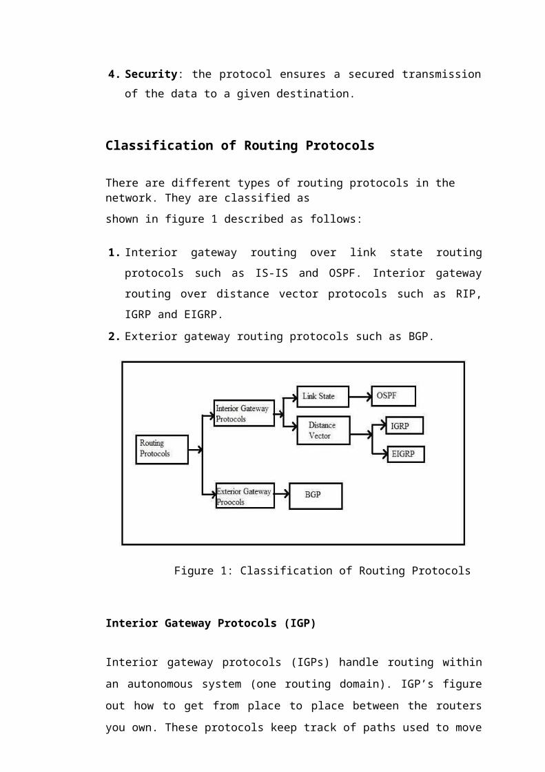
There are different types of routing protocols in the network. They are classified as
shown in figure 1 described as follows:
1. Interior gateway routing over link state routing protocols such as IS-IS and OSPF. Interior gateway routing over distance vector protocols such as RIP, IGRP and EIGRP.
2. Exterior gateway routing protocols such as BGP.
Figure 1: Classification of Routing Protocols
Interior Gateway Protocols (IGP)
Interior gateway protocols (IGPs) handle routing within an autonomous system (one
routing domain). IGP’s figure out how to get from place to place between the routers
you own. These protocols keep track of paths used to move data from one end system
to another inside a network or set of networks that you administrate (all of the
networks we manage combined are usually just one Autonomous System). IGPs are
how all the networks are communicating with each other.
7

Autonomous System (AS): This is a collection of networks that is within the administration control of an organization or company that shares a common routing strategy.
IGPs fall into two categories:
1. Link State Protocols
2. Distance Vector Protocols
Link State Routing Protocol
In link state routing protocols, each router possesses information about the complete
network topology. Each router then independently calculates the best next hop from
it for every possible destination in the network using local information of the
topology. The collection of best- next-hops forms the routing table. This contrasts
with distance-vector routing protocols, which work by having each node share its
routing table with its neighbors. In a link state protocol, the only information passed
between the nodes is information used to construct the connectivity maps.
1. Link State Routing (LSR) determine the shortest path among the network. Each router maintains a database called link state database. It is mainly used to describe the topology of the AS.
2. The Link State Advertisements (LSA) is responsible for exchanging the routing information among the nodes. The information of the neighbors is found in each
LSA of a node and any change in link information of a neighbor’s node is
communicated through LSAs b flooding. Usually the nodes observe the change
when the LSAs are received. Then the routes are calculated again and resent to
their neighbors. As a result, all nodes can maintain an identical database where
they describe the topology of the networks.
Example of link-state routing protocol is Open Shortest Path First (OSPF).
8

Open Shortest Path First (OSPF)
Open shortest Path First (OSPF) is a link state routing protocol, operating within a single Autonomous System (AS).
In large enterprise networks, OSPF is most widely used. OSPF was designed to support
variable length subnet masking (VLSM) or classless inter domain routing (CIDR)
addressing models. Link failures are detected by OSPF very quickly and new loop free
rote is converged. Dijkstra’s algorithm is used to calculate the shortest path tree. A link
state database (LSDB) stores all the information of link state for each router. LSDB
possess a tree like structure of the network topology. LSDB is updated periodically by
flooding all the routers. OSPF requires high memory and is a little difficult to.
Shortest Path First (SPF) Algorithm
1. A link state advertisement is generated by a router whenever there is a change in the
routing information. Link state is provided to the router by this advertisement.
2. Flooding is done for routers to exchange LSAs. Each router receives a link state update which is also preserved in link state database. This update is propagated to other routers.
3. Routers after creation of there database, calculate the shortest path tree to the destinations for which the Dijkstra’s algorithm is used.
4. New network will be added or deleted whenever any there occurs a change in the network (e.g. link cost). Again the Dijstra’s algorithm is calculated to get the least value of cost path.
OSPF Metrics
OSPF uses the following metrics:
1. Hop count: The count of the number of routers through which the packet travels to reach the destination.
2. Bandwidth: The bandwidth speed is checked.
9

OSPF Packet Header
OSPF packets are composed of eight fields as shown in figure 2.2:
Version Type
Router ID
Area ID
Checksum AuType
Authentication
Authentication
Figure 2: OSPF Packet Header
Each field is defined as follows:
1. Version: The versions types are defined.
2. Type: The packet type is defined.
1. Hello
2. Database description(DBD)
3. Link state request(LSR)
4. Link state update(LSU)
5. Link state acknowledgement(LSAck)
3. Router ID: Source router ID is defined.
4. Area ID: Area ID of packet is defined.
5. Checksum: Damaged packets are checked.
6. Au Type: Authentication type is defined. Three type of authentications exist:
1. Null authentication: No authentication is done.
2. Clear text authentication: Passwords are exchanged in clear text over the network.
3. Cryptographic authentication: Message Digest 5 encryption method is used for the authentication.
7. Authentication: Integrity of routing packet is defined.
10

OSPF Packet Types
1. Hello: Neighbors are discovered and adjacency is established with other OSPF routers by sending this packet.
2. Database Description: Link state database description is exchanged between adjacent routers after a connection is made by sending the Hello packet.
3. Link state Request Packet: Link state request packet is used by receiving routers to get the information about any entry in the DBD after the database description is exchanged.
4. Link State Update: Flooding is done using this packet in the link state advertisement to LSR.
5. Link State Acknowledgement Packet: Routers send a link state acknowledgement to confirm the senders as LSU is received reliably.
OSPF Path Cost
The path cost in OSPF is calculated based on the bandwidth. Cost is inversely proportional to the bandwidth. Higher bandwidth is attained with a lower cost.
Cost =106 / Bandwidth (bps) [eq. 1]
Advantages of OSPF
OSPF has following advantages:
1. The routes of OSPF are always loop free. OSPF quickly updates all the routers over large complex networks whenever a change occurs in the network.
2. OSPF support multiple routes.
3. OSPF configures the area and reduces the size and hence, minimizing the routes.
4. Reconfiguration for network topology changes is faster.
5. Variable length subnet masking is supported.
6. It is suitable for large network.
11
Disadvantages of OSPF
1. OSPF requires more computing power in a router as it handles large complex
networks which becomes difficult for the network manager to set up and
configure the protocol.
2. A proper understanding and calculation by the manager is required for the path cost used by the router for data exchanges with other routers.
Distance-vector routing protocol
Bellman-Ford algorithm is used in Distance Vector Routing Protocol. This protocol
do not show the whole network topology information. The other routers calculate the
distance value and the protocol advertises that value and from other routers, receive
the similar advertisements in the network. While advertising the routes, the routing
table is populated by each router. An updated information is advertised by the router
in the next routing table. Until stable values of routing tables of each router are
converged, the process continues. Slow convergence is a disadvantage occurring in
some protocols.
Example of distance vector routing protocols:
1. Interior Gateway Routing Protocol(IGRP)
2. Enhanced Interior Gateway Routing Protocol(EIGRP)
12

1. Interior Gateway Routing Protocol (IGRP)
Interior Gateway Routing Protocol is a routing protocol to provide routing within an
Autonomous System (AS). Distance vector routing protocols calls for each router to
send all or a portion of its routing table in a routing update message at regular
intervals to each of its neighboring routers. IGRP is considered as an IGP, but it can
also be considered as an EGP when inter-domain routing happens. Distances to all
nodes inside an internetwork can be calculated by the routers as the routing
information flourishes through the network. IGRP is a classful routing protocol
requiring an Autonomous System (AS) number in its configuration and uses only the
IP routing. Every 90 seconds IGRP sends periodic routing updates along with the full
updated routing table of each. The metric used by the protocol is the Distance metric.
By default, this metric is calculated by the Bandwidth, and Delay of Line metrics.
IGRP provides some optional attributes that can also be used to calculate the distance
metric like reliability, load, and MTU. By Default, IGRP supports a maximum of 100
hops but it can be made to 255 hops. Routers in the same Autonomous system will
send updates to each other.
IGRP Characteristics
1. It is a distance vector routing protocol.
2. Every 90 seconds, a routing update is broadcasted.
3. By default supports 100 hops.
4. Bandwidth, Load, Reliability and Delay are used to create a composite metric.
5. While configuration, same autonomous number is used by all routers.
IGRP metrics
Priorities of the metrics are considered.
1. Bandwidth: Lowest bandwidth in a route is preferred.
2. Delay: Time taken by packets to pass through the network.
3. Reliability: Reliability towards the destination node on the link.
4. Load: Effective bandwidth over the path.
13

IGRP Timers
1. Update Timers: frequency to send routing update messages is defined. By default, it is 90 seconds.
2. Invalid Timers: Duration to wait is defined for a router before it is declared invalid if no update is received for it. By default, it is 3*90-270 seconds.
3. Holddown Timers: specifies the holddown period. The default is three times the update timer period plus 10 seconds. (i.e. 270+10=280)
4. Flush Timers: Before flushing the router from a routing table, this specifies the
amount of time to pass. By default, it is seven times the routing update period. If the
update timer is 90 seconds by default, then 7*90=630 seconds elapse before a route
will be flushed from the route table. (igrp-28789476?from_search=1, n.d.)
IGRP Goals
The IGRP protocol allows a number of gateways to coordinate their routing. The goals
of IGRP are as follows:
1. When changes occur, IGRP should response fast in network topology.
2. Taking into account error rates and level of traffic on different paths.
3. Splitting traffic among several parallel routes when they are of roughly equal desirability.
4. Stable routing even in very large or complex networks. No routing loops should occur, even as transients.
5. Low overhead. That is, IGRP itself should not use more bandwidth that what is actually needed for its task. (An Introduction to IGRP, n.d.)
IGRP is an Internal Gateway Protocol (IGP). IGPs are intended for use within single set
of networks, either under a single management or closely coordinated managements.
Such sets of networks are connected by ‘external gateway protocols’ (EGP). An IGP is
designed to keep track of a good deal of detail about network topology. Priority in
designing an IGP is placed on producing optimal routes and responding quickly to
changes. An EGP is intended to protect one system of networks against errors or
intentional misrepresentation by other systems, BGP one such EGP. Priority in designing
an EGP is on stability and administrative controls. Often it is
14

sufficient for an EGP to produce a reasonable route, rather than the optimal route. (An Introduction to IGRP, n.d.)
The Routing Problem
IGRP is intended for use in gateways connecting several networks. The gateway act
as packet switches. When a system connected to one network wants to send s packet
to a system on a different network, it addresses the packet to a gateway. If the
destination is on one of the networks connected to the gateway, the gateway will
forward the packet to another gateway that is closer to the destination. Gateways are
routing tables to help them decide what to do with packets. (An Introduction to
IGRP, n.d.)
IGRP Working
A path is characterized by the next gateway to which packets should be sent, the
network interface that should be used, and metric information. Metric information is
a set of numbers that characterize how good the path is. This allows the gateway to
compare paths that it has heard from various gateways and decide which one to use.
There are often cases where it makes sense to split traffic between two or more paths.
IGRP will do this whenever two or more paths are equally good. The user user can
also configure it to split traffic when paths are almost equally good. In this case more
traffic will be sent along the path with the better metric. The intent is that traffic can
be split between a 9600 bps line and a 19200 bps line, and 19200 line will get
roughly twice as much as traffic as 9600 bps line. The metrics used by IGRP include:
1. Topological delay time
2. Bandwidth of the narrowest bandwidth segment of the path
3. Channel occupancy of the path
4. Reliability of the path
Topological delay time is the amount of time it would take to get to the destination
along the path, assuming an unloaded network. The path bandwidth is simply the
bandwidth in bits per second of the lowest link in the path. Channel occupancy
indicates how much of the bandwidth is currently in use. It is measured, and will
15

change with load. Reliability indicates the current error rate. It is the fraction of packets that arrive at the destination undamaged. It is measured.
Although they are not used as part of the metric, two addition pieces of information are passed with it: hop count and MTU.
1. The hop count is simply the number of gateways that a packet will have to go through to get to the destination.
2. MTU is the maximum packet size that can be sent along the entire path along without fragmentation. (it is the minimum of the MTUs of all the networks involved in the path)
Based on the metric information, a single ‘composite metric’ is calculated for the path.
The composite metric combines the effect of the various metric components into a single number representing the goodness of the path.
There are two advantages of using a vector of metric information.
1. The first is that it provides the ability to support multiple types of service from the same set of data;
2. The second is improved accuracy. (An Introduction to IGRP, n.d.)
The following equation calculates the metric.
1. Delay = delay from packet + interface topological delay.
2. Bandwidth = max(bandwidth from packet, interface bandwidth).
3. Reliability = min(reliability from packet, interface reliability).
4. Channel Occupancy = max(channel occupancy from packet,interface channel occupancy). (An Introduction to IGRP, n.d.)
16

1. Enhanced Interior Gateway Protocol (EIGRP)
EIGRP is an enhanced version of IGRP. The same distance vector technology is used in
EIGRP as is in IGRP. The convergence properties and the underlying distance
information remain unchanged. This protocol performs more efficient than the IGRP.
Subnet mask information is carried by EIGRP. EIGRP supports classless route lookups
and Variable Length Subnet Masks (VLSM). Arbitrary bit bound boundaries can be
summarized by EIGRP. The Diffusing Update Algorithm (DUAL) is used to get loop
free routes throughout a root computation at every instant. This allows all routers
involved in a topology change to synchronize at the same time. Routers that are not
affected by topology changes are not involved in the recomputaion. EIGRP requires
acknowledgements from routing updates. DUAL allows rapid convergence. EIGRP
performs route summarization automatically by default.
Packet types of EIGRP
1. Hello: Neighbors are discovered and adjacency is established with other EIGRP routers by sending this packet.
2. Update: Whenever a change occurs in the network, this packet is sent to the routers
3. Ack: Acknowledges receipt of an update using a unicast address.
4. Query/Reply: These are sent when destinations go into active state. Queries are
always multicast unless they are sent in response to a received query. Replies
are unicast. Also when a router loses its successor and has no feasible successor
it queries all remaining neighbor for a new route queries are recursive and will
be forwarded to the neighbors until a new route is found.
5. Request: These are used to get specific information from one or more neighbors. These are transmitted unreliably. (EIGRP, n.d.)
EIGRP Working
Initial Route Discovery.
1. Router sends hello.
2. Neighbor router replies with an Update.
3. The router sends an Ack packet.
17

4. From the opposite direction, Update replies are given.
EIGRP has four basic components, these are as follows:
1. Neighbor Discovery/Recovery: This is the process that routers use to
dynamically learn of other routers on their directly attached networks. Routers
must also discover when their neighbors become unreachable or inoperative.
This process is achieved with low overhead by periodically sending small hello
packets. As long as hello packets are received, a router can determine that a
neighbor is alive and functioning. Once this is determined, the neighboring
routers can exchange routing information.
2. Reliable Transport Protocol: This is responsible for guaranteed, ordered delivery
of EIGRP packets to all neighbors. It supports intermixed transmission of multicast
or unicast packets. Some EIGRP packets must be transmitted reliably and others
need not. For efficiency, reliability is provided only necessary. For examples, on a
multi-access network that has multicast capabilities, such as Ethernet, it is not
necessary to send hellos reliably to all neighbors individually. So EIGRP sends a
single multicast hello with an indication in the packet informing the receivers that
the packet need not be acknowledged. Other types of packets, such as updates,
require acknowledgement and this is indicated in the packet. The reliable transport
has a provision to send multicast packets quickly when there are unacknowledged
packets pending.
3. DUAL Finite State Machine: This embodies the decision process for all route
computations. It tracks all routes advertised by all neighbors. A metric is used by
DUAL to select efficient loop free paths. DUAL selects routes to be inserted into a
routing table based on feasible successors. A successor is a neighboring router used
for packet forwarding that has a least cost path to destination that is guaranteed not
to be part of a routing loop. When there are no feasible successors but there are
neighbors advertising the destination, a recomputation must occur. This is the
process where a new successor is determined. The amount of time it takes to
recompute the route affects the convergence time. When a topology
18

change occurs, DUAL will test for feasible successors. If present, it will use any
successor in order to avoid any unnecessary recomputation.
4. Protocol Dependent Modules: these are responsible for network layer,
protocol-specific requirements. The IP_EIGRP module is responsible for
sending and receiving EIGRP packets that are encapsulated in IP. It parses the
packets and informs DUAL of the new information received. It asks DUAL to
make routing decisions and results of this are stored in the IP routing table. It is
also responsible for redistributing routes learned by other IP routing protocols.
(technologies_tech_note09186a0080093f07.shtml, n.d.)
There are some parameters that must match for the routers to become adjacent:
1. Authentication
2. AS number
3. Must believe that the source IP address of the hello packet is the primary IP address of the source interface, secondary IP address will not allow the adjacency to form.
4. K values.
Metric calculation
[eq.2]
1. Bandwidth(bw): defined as 107 divided by the speed of the slowest link in the path, in Kbps.
2. Load: 8-bit value, not considered by default.
3. Reliability: 8-bit value, not considered by default.
4. Delay: constant value associated with interface type; EIGRP uses the sum of all delays in the path.
K values
K values are constants used to distribute weight to different path aspects.
K defaults:
19
1. K1: 1
2. K2: 0
3. K3: 1
4. K4: 0
5. K5: 0
K values can be manipulated by an administrator, but routers must have matching K values to become neighbors. Neighbor reset after retry limit of 16 is reached. Slow neighbors are sent unicast packets. (EIGRP, n.d.)
EIGRP Tables
The EIGRP tables are:
1. Neighbor Tables: Information about the neighbor EIGRP routers the present in this table.
1. Network Address (IP).
2. Connected interface.
3. Holdtime of the neighbor.
4. Update.
5. Sequence numbers.
6. Retransmission Timeout (RTO): Calculated by SRTT, this tells the waiting duration of the router for an Ack.
7. Smooth Round Trip Time (SRTT): Once a packet has been transmitted, this tells the time it taken to receive an Ack.
8. Queue Count: Describes the number of routers present in the queue. Congestion is sensed if there is a long queue.
2. Topology Table: All the routes received from the neighbors are present in this table. DUAL is used to calculate them. To construct the EIGRP routing table, topology table bears the required information. (EIGRP, n.d.)
Advantages of EIGRP
1. It is more efficient than IGRP.
2. Very fast rapid convergence times for changes in the network topology.
20

3. When a change occurs, there is change only in the routing table.
4. Support aggregation and variable length subnet masks.
Exterior Gateway Protocols (EGP)
EGP is used on the Internet to go from one network to another. Routing outside an
AS is handled by EGP. Via the Internet Service Provider’s (ISP) network, EGP get
us to different networks. BGP is used by companies with more than one ISP to allow
them to have redundancy and load balancing of their data transferred to and from the
network.
1. Broadcast Gateway Protocol (BGP)
Border Gateway Protocol is an exterior gateway routing protocol (EGP) that is used
to by an Autonomous System (AS) to share the route information to get the best
routes which are loop free. The Internet Service Providers (ISPs) use BGP internally.
Classless Inter Domain Routing (CIDR) is supported by the mechanisms set provided
by BGP. The mechanisms are providing support to advertise the destinations set as
an IP prefix and removing the concept of classes in BGP. It allows aggregation of
routes of AS paths. When routing information is exchanged using BGP, only the
destination based forwarding paradigm is supported by the protocol. In forwarding
paradigm it is considered that forwarding of a packet by a router base on destination
address as specified in the packet IP header. BGP is a path vector routing protocol. It
is successor of the Exterior Gateway Protocol (EGP) and allows fully decentralized
routing. Version 4 of BGP is the current version being used.
BGP speaker inform the peers about the non-availability of the route advertised previously by the following methods provided by BGP. The methods for this are as following:
1. The IP prefix that expresses the destination for a previously advertised route can be advertised in the Withdrawn Routes field in the Update message, thus, marking the associated root as being no longer available for use.
2. A replacement route with the same Network Layer Reachability Information (NLRI) can be advertised.
21

3. The BGP speaker connection can be closed, which implicitly removes all routes the pair of speaker had advertised to each other from service. (RFC4271, n.d.)
BGP Attributes
Routes learned via BGP have associated properties that are used to determine the best
route to a destination when multiple paths exist to a particular destination. These
properties are referred to as BGP attributes, and an understanding of how BGP
attributes influence route selection is required for the design of robust networks. The
attributes are:
1. Weight
2. Local Preference
3. Multi-exit discriminator
4. Origin 5. AS_path 6. Next Hop
Weight Attribute
Weight attribute is local to a router. It is not advertised to neighboring routers. If the router learns about more than one route to the same destination, the route with the highest weight will be preferred. The route with the highest weight will be installed in the IP routing table.
Local Preference Attribute
The local preference attribute is used to prefer an exit point from the local autonomous system (AS). Unlike, the weight attribute, this attribute is propagated throughout the local AS. If there are multiple exit points from the AS, the local preference attribute is used to select the exit point for a specific route.
Multi Exit Discriminator Attribute
The multi-exit discriminator (MED) or metric attribute is used as a suggestion to an external AS regarding the preferred route into the AS that is advertising the metric. The term suggestion is used because the external AS that is receiving the MED’s may be using other BGP attributes for route selection.
22

Origin Attribute
The origin attribute indicates how BGP learned about a particular route. The origin attribute can have three possible values:
1. IGP: The route is interior to the originating AS. This value is set when the network router configuration is used to inject route into BGP.
2. EGP: The route is learned via the EGP. 3. Incomplete: The origin of the route is unknown or learned in some other way. An
origin of incomplete occurs when a route is redistributed into BGP. The origin attribute is used for route selection.
AS-path Attribute
When a route advertisement passes through an AS, the AS number is added to an ordered list of AS numbers that the advertisement has traversed.
Next Hop Attribute
The next hop attribute is the IP address that is used to reach the advertising router. For EBGP peers, the next-hop address is the IP address of the connection between the the peers. For IBGP, the EBGP next-hop address is carried into the local AS.
Community Attribute
The community attribute provides a way of grouping destinations, called
communities, to which routing decisions (such as acceptance, preference, and
redistribution) can be applied. Route maps are used to set the community attribute.
Predefined community attributes are:
1. No-export: do not advertise this route to EBGP peers.
2. No-advertise: do not advertise this route to any peer.
3. Internet: advertise this route to the internet community; all routers in the network belong to it.
BGP Path Selection
BGP could possibly receive multiple advertisements for the same route from multiple
sources. BGP selects only one path as the best path. When the path is selected BGP puts
the selected path in the IP routing table and propagates the path to its neighbors. BGP
uses the following criteria, in the order resented. To select a path for a destination:
23

1. If the path specifies a next hop that is inaccessible, drop the update.
2. Prefer the path with the largest weight.
3. If the weights are same, prefer the path with the largest local preference.
4. If the local preferences are the same, prefer the path that was originated by BGP running on this router.
5. If no route was originated, prefer the route that has the shortest AS_path.
6. If all paths have the same AS_path, length, prefer the path with the lowest origin type (where origin is lower than EGP, and EGP is lower than incomplete).
7. If the origin codes are the same, prefer the path with the lowest MED attribute.
8. If the paths have the same MED, prefer the external path over the internal path.
9. If the paths are still the same, prefer the path through the closest IGP neighbor.
10. Prefer the path with the lowest IP address, as specified by the BGP router ID. (Border_Gateway_Protocol#BGP_Attributes, n.d.)
Message Header Format
Following is the message header format:
Figure 3: Message header format
1. Marker: included for compatibility, must be set to all ones.
2. Length: total length of the message in octets, including the header.
3. Type: Type of BGP message. The following are defined: 1. Open(1)
2. Update(2)
3. Notification(3)
4. KeepAlive(4)
24

Operation of BGP
BGP neighbors, called peers, are established by manual configuration between
routers to create a TCP session port 179. A BGP speaker sends 19-byte keep-alive
messages every 30 seconds to maintain the connection. Among routing protocols,
BGP is unique in using TCP as its transport protocol. (BGP, n.d.)
BGP running in the same Autonomous System (AS) is called Internal BGP (iBGP);
and running in different AS is called External BGP (eBGP). Routers that exchange
information over the boundary of an AS with another AS are called border routers
or eBGP peers connect directly. iBGP peers are connected to each other via
intermediate routers. The main difference between iBGP and eBGP peering is in the
way routes that were received from one peer are propagated to other peers. New
routes learnt fom eBGP are typically redistributed to all othe iBGP peers as well as
all eBGP peers, while, new routes learnt on an iBGP peering, they are re-advertised
only to all other eBGP peers.
Extension negotiation
During the peering handshake, when OPEN messages are exchanged, BGP speakers
can negotiate optional capabilities of the session, including multiprotocol extensions
and various recovery modes. If the multiprotocol extensions to BGP are negotiated at
the time of creation, the BGP speaker can prefix the Network Layer Rechability
Information (NLRI) it advertises with an address family prefix. These families
include the IPv4 (default), IPv6, IPv4/IPv6 VPN and multicast BGP.
Finite State Machine (FSM)
When making decisions with peers, a BGP peer uses a simple FSM that consists of six states: Idle; Connect; Active; OpenSent; OpenConfirm; and Established.
1. Idle State:
1. Refuses all incoming BGP connections
2. Start the initialization of event triggers.
3. Initiates a TCP connection with its configured peer.
4. Listens for a TCP connection from its peer.
5. Changes its state to connect.
6. If an error occurs at any state FSM process, the BGP session is terminated immediately and returned to the idle state. Some of the reasons why a router does not progress from the Idle Sate are:
25

1. TCP port 179 is not open.
2. A random TCP port over 1023 is not open.
3. Peer address configured incorrectly on either router.
4. AS number configured incorrectly on either router.
2. Connect State
1. Waits for successful TCP negotiation with peer.
2. Sends Open message to peer and changes state to OpenSent.
3. If an error occurs, BGP moves to the Active state. Reasons for this are same as are for the Idle Sate.
3. Active State
1. If the router was unable to establish a successful TCP session, then it ends up in the Active State.
2. BGP FSM tries to restart another TCP session with the peer and, if successful, sends an Open message to the peer.
3. If unsuccessful again, the FSM is reset to the Idle State.
4. Repeated failures may result in a router cycling between the Idle and Active state. Some reasons are:
1. TCP port 179 is not open.
2. A random TCP port over 1023 is not open. BGP configuration error.
3. Network congestion.
4. OpenSent State
1. BGP FSM listens for an Open message from its peer.
2. Once the message has been received, the router checks the validity of the Open message.
3. If there is an error it is because of the fields in the Open message does not match between the peers. The router sends a Notification message to the peer indicating why the error occurred.
4. If there is no error, a KeepAlive message is sent, various timers are set and the state is changed to OpenConfirm.
5. OpenConfirm State
1. The peer is listening for a KeepAlive message from its peer.
2. If a KeepAlive message is received and no timer has expired before reception of the KeepAlive, BGP transitions to the Established state.
26

3. If a timer expires before a KeepAlive message is received, or if an error condition occurs, the router transitions back to the Idle state.
6. Established State
1. The peers send Update messages to exchange information anout each route being advertised to the BGP peer.
2. If there is any error in the Update message then a Notification message is sent to the peer, and BGP transitions back to the Idle state.
3. If a timer expires before a KeepAlive message is received, or if an error condition occurs, the router transitions back to the Idle state. (BGP, n.d.)
Uses of BGP
1. Very large private IP networks use BGP internally. An, example would be the joining of a number of large OSPF networks where OSPF by itself would not scale to size. (BGP-border gateway protocol, n.d.)
2. BGP is also used for multihoming a network for better redundancy, either to multiple access points of a single ISP or to multiple ISPs. (BGP, n.d.)
27
CHAPTER 3 SYSTEM FLOWCHART AND LOGICAL DIAGRAMS
The various steps involved in simulation are described in figure 4 shown as below.
Figure 4: Steps to develop and analyze protocols
As demonstrated in figure 4, the steps are defined below.
1. Develop Scenarios: In this step different scenarios are developed to configure with the different routing protocols.
2. Choose statistics: Second step after developing the scenarios is to select the various statistics for the different scenarios according to the configured protocol.
3. Run Simulation: In this, comparison of various parameters and the results of the scenarios are collected.
4. Analyze Result: After collecting the results, these results are analyzed in this final step for comparison among the BGP, IGRP, OSPF and EIGRP.
28

CHAPTER 4 RESULTS AND DISCUSSIONS
Simulation
Simulation can be defined to show the eventual real behavior of a selected system model. On the basis of system, it is used to optimize performance so that an insight of the functioning of system is obtained. Simulation results are can be used to get an estimation and assumption of the real system.
Simulator
In this project, network simulator, Optimized Network Engineering Tools (OPNET) modeler 9.1 has been used as a simulation environment. OPNET is a simulator built on top of discrete even system (DES) and by modeling each event in the system, it simulates the system behavior and user defined processes are used to process it. OPNET is very powerful software to stimulate heterogeneous network with various protocols.
Structure of the OPNET
OPNET is a high level user interface that is built as of C and C++ source code with huge library of OPNET function.
4.3.1 Hierarchical Structure
OPNET model is divided into three domains:
1. Network Domain: Network domain can include Physical connection, interconnection and configuration. Overall system is represented, e.g. a network on a geographical map to be simulated.
2. Node Domain: This is present in the Network domain as an internal infrastructure. E.g. routers, hubs, workstations, etc.
3. Process Domain: This domain tells the attributes of the processor and queue model inside the node models by using source code C and C++.
29

Simulation Study
The protocols used here are BGP, IGRP, EIGRP, and OSPF. The proposed routing protocols are implemented and evaluated. These protocols are intended to use to get better performance of one over the other for real time traffic.
Results
Topology considered and the resulting graphs for OSPF
Figure 5: Topology considered for OSPF.
Configuring the link cost
Cost considered using eq.1 for all the links configured with OSPF.
30

Figure 6: OSPF protocol
showing the traffic sent.
Figure 7: OSPF protocol showing
the traffic received.

Figure 8 Figure 9
Figure 8 & 9: Highlighted link showing the shortest path followed by OSPF.
31

Topology considered and the resulting graphs for IGRP
Figure 10: Network considered for Figure 11: Topology considered inside
IGRP. the network.

Figure 12: IGRP protocol
showing the traffic sent.
32
Figure 13: IGRP protocol showing
the traffic received.

Figure 14: IGRP protocol showing the traffic send VS traffic received.
Topology considered and the resulting graphs for EIGRP
Figure 15: Network considered for Figure 16: Topology considered inside
EIGRP. the network.
33

Figure 17: EIGRP protocol
showing the traffic sent.
Figure 18: IGRP protocol showing
the traffic received.

Figure 19: EIGRP protocol showing the traffic send VS traffic received.
34

Topology considered and the resulting graphs for BGP
Figure 20: Topology considered for BGP.

Figure 21: BGP protocol
showing the traffic sent.
35
Figure 22: BGP protocol
showing the traffic received.

Figure 23: BGP protocol showing the global traffic received VS traffic received on Router 14.
36

Graph showing comparison between IGRP and EIGRP
Figure 24: Simulation Information of IGRP & EIGRP.
Figure 25: Simulation Result of EIGRP Figure 26: Simulation Result of IGRP
37

Figure 27: Comparison between IGRP (traffic sent & received) and EIGRP (traffic sent & received).
38

CHAPTER 5 SCOPE OF THE WORK
The main aim to conduct this project is to learn about the behavior of the IGRP, OSPF, BGP and EIGRP. The driving factor is the uniqueness present in the project with respect to parameters being evaluated. Various parameters and constraints have been studied.
The evaluation of the protocol by considering a set of parameters and comparing the results with the other protocol’s outcome yields a better understanding towards the behavior of the protocol. A better understanding of the routing protocol helps in better implementation in the real time networks, which helps in obtaining optimum output and efficient working of the system. This in turn, helps in improvement of the overall network behavior. This project presents the simulation model which is created for the analysis of the routing protocols: IGRP, BGP, OSPF and EIGRP.
OSPF was designed for the specific networks and had a very loose relation with the other protocols, was bit complex to apply and overhead between them was minimal. There are few considerable differences between these such as theories in electing the designed router (DR), passing over the upper layer information to other areas and parameter synchronization.
39

CHAPTER 6 CONCLUSION
1. The IT Guru software allows for rapid creation of large nets. These nets can be configured using the graphical user interface (GUI), which simplify usage.
2. Interior routing protocols like IGRP, EIGRP and OSPF are widely being used in computer networking.
3. Exterior routing protocols like BGP and BGP4 are also used in computer networking.
4. In this project, we have implemented selected routing protocols such as IGRP, EIGRP, OSPF and BGP.
5. On implementing these protocols, we have measured the performance metrics for real time applications which measures the differences between the delays of packets.
6. On comparing IGRP and EIGRP, we have found EIGRP performing better than IGRP.
40
CHAPTER 7 BIBLIOGRAPHY
1. Md. Nazrul Islam and Md. Ahsan Ullah Ashique, Simulation Based EIGRP over OSPF Performance Analysis, 2010. (n.d.).
2. Mohsen Emami, Performance Comparison of BGP in Multi-AS Network with Opnet Simulator. (n.d.).
3. An Introduction to IGRP. (n.d.). Retrieved from http://www.cisco.com/: http://www.cisco.com/en/US/tech/tk365/technologies_white_paper09186a00800 c8ae1.shtml#details
4. BGP. (n.d.). Retrieved from www.wikipedia.org: http://en.wikipedia.org/wiki/BGP
5. BGP-border gateway protocol. (n.d.). Retrieved from www.networkguruz.com: http://www.networkguruz.com/protocols/bgp-border-gateway-protocol/
6. Border_Gateway_Protocol#BGP_Attributes. (n.d.). Retrieved from http://www.docwiki.cisco.com/: http://docwiki.cisco.com/wiki/Border_Gateway_Protocol#BGP_Attributes
7. EIGRP. (n.d.). Retrieved from http://packetlife.net/: http://packetlife.net/wiki/eigrp/
8. igrp-28789476?from_search=1. (n.d.). Retrieved from http://www.slideshare.net/: http://www.slideshare.net/mohammedfarismajeed/igrp-28789476?from_search=1
9. RFC4271. (n.d.). Retrieved from http://www.tools.ietf.org: http://tools.ietf.org/html/rfc4271
10. technologies_tech_note09186a0080093f07.shtml. (n.d.). Retrieved from http://www.cisco.com/: http://www.cisco.com/en/US/tech/tk365/technologies_tech_note09186a0080093 f07.shtml
11. Tony Dongliang Feng, Implementation of BGP in a network simulator, 1997. (n.d.). Retrieved from https://www.google.co.in/url?sa=t&rct=j&q=&esrc=s&source=web&cd=2&cad=rja &ved=0CDIQFjAB&url=http%3A%2F%2Fwww.ensc.sfu.ca%2F~ljilja%2Fcnl%2Fpdf% 2Ftony.pdf&ei=JhCgUrTMFYeFrAeah4CwCQ&us
41