WITH MULTIPLE CONSTRAINTS Edward S. Zorzi, C. … · WITH MULTIPLE CONSTRAINTS Edward S. Zorzi, ......
19
DEVELOPMENT AND APPLICATION OF A UNIFIED BALANCING APPROACH WITH MULTIPLE CONSTRAINTS Edward S. Zorzi, C. Chester Lee, John C. Giordano Mechanical Technology Incorporated 968 Albany-Shaker Road Latham, New York 12110 The development of a unified balancing approach with multiple constraints offers the engineer a power- ful and flexible tool, broad in scope and not restricted to special rotor configurations. This meth- od imposes no restrictions on the use of modal trail weight sets and/or modal influence coefficients, which have been proven effective for balancing high-speed rotors in previous "unified" approaches. This approach overcomes the limitations of earlier unifying efforts by permitting the application of orbit and/or weight constraints at any balancing speed not just at critical speeds. Modal trial weight sets for subsequent balanc- ing can be predicted which will not disturb previously balanced speeds. An orbit constraint applied at an off-critical speed will only affect that individual orbit, but if applied at a critical speed, will affect all orbits and constrain the entire mode shape. In addition, correction weights may be constrained at any balance speed if, for example, a balance plane becomes unavailable (i.e. maxim weight removal limit reached) or if redundant planes exist. ,Thismethod provides an analytic extension of the general influence coefficient methods and offers a least squares formulation that incorporates the constraints within the optimization procedure. A special test facility is described which has been used to evaluate this approach to balancing. As https://ntrs.nasa.gov/search.jsp?R=19850018580 2018-07-27T10:28:28+00:00Z
Transcript of WITH MULTIPLE CONSTRAINTS Edward S. Zorzi, C. … · WITH MULTIPLE CONSTRAINTS Edward S. Zorzi, ......
DEVELOPMENT AND APPLICATION OF A UNIFIED BALANCING APPROACH
WITH MULTIPLE CONSTRAINTS
Edward S. Zorzi, C. Chester Lee, John C. Giordano Mechanical Technology Incorporated
968 Albany-Shaker Road Latham, New York 12110
The development of a unified balancing approach with multiple constraints offers the engineer a power- ful and flexible tool, broad in scope and not restricted to special rotor configurations. This meth- od imposes no restrictions on the use of modal trail weight sets and/or modal influence coefficients, which have been proven effective for balancing high-speed rotors in previous "unified" approaches. This approach overcomes the limitations of earlier unifying efforts by permitting the application of orbit and/or weight constraints at any balancing speed not just at critical speeds. Modal trial weight sets for subsequent balanc- ing can be predicted which will not disturb previously balanced speeds. An orbit constraint applied at an off-critical speed will only affect that individual orbit, but if applied at a critical speed, will affect all orbits and constrain the entire mode shape. In addition, correction weights may be constrained at any balance speed if, for example, a balance plane becomes unavailable (i.e. maxim weight removal limit reached) or if redundant planes exist. ,This method provides an analytic extension of the general influence coefficient methods and offers a least squares formulation that incorporates the constraints within the optimization procedure.
A special test facility is described which has been used to evaluate this approach to balancing. As
https://ntrs.nasa.gov/search.jsp?R=19850018580 2018-07-27T10:28:28+00:00Z
demonstrated, the analytic approach has been fully tested and found to be easily implemented. Test results compare favorably with the analytic methodology offered, No special problems have been encountered either in software implementation or obtaining excel- lent correlation from test rig experimental results*
Two widely used and distinct linear approaches to balancing have been developed within the past 20 years, One is the modal approach, which has been widely accepted by industry and has been very effective in balancing a wide variety of high-speed rotating equip- ment El] .* The other approach consists of a group of balancing procedures, generally classified as influence coefficient methods, which has also attracted many supporters [2,3]. Recent publications have focused on the at t tact ivenes s of a combined or so-called "unified" approach, Darlow et al., [ 4 , 5 ] . The unified technique defines the use of !nodal trial weights which do not disturb previously balanced critical speeds (modes) and that are used to determine influence coefficients, me modal trial and correction weights are prescribed from experimentally detemined influence coefficients, thus coupling the advantages of a modal technique with the influence coefficient approach,
These 'knifying" efforts have encountered limitaa- tians in determining correction weights. The earlier approachs are, in effect, modal methods since they are predicated on the control of all orbits at a speed with a single modal weight set. Generally, such a procedure is not sufficient for balancing at off-critical speeds, such as balancing gas turbines at operating speed* To address this limitation, a final trim balance, using standard influence coefficient balancing, has been recamended 24.1, It is apparent that these unifying approaches use a form of modal balancing to traverse critical speeds and the standard 2nfluence coefficient approach for trim balancing. This procedure is Limited when general coupled modes are present or when spchro- nous orbit control is required at both the critical speed and at off-critical speeds. A truly unified approach would offer a single, integrated solution form for both steps and allow the engineer to evaluate the
*Hmbers in brackets refer to references.
trade-offs between balancing at the critical speeds and at off-critical speeds E61, If modal constraints are to be imposed, the general flexibility of the influence coefficient balancing method should be extended to include such constraints.
This work describes the development of a general analytic approach to constrained balancing that is consistent with past influence coefficient methods (weighted least squares, point speed, etc,). The approach uses Lagrange multipliers [ 7 1 to impose orbit and/or weight constraints; these constraints are combined with the least squares minimization process to provide a set of coupled equations that result in a single solution form for determining correction weights, Proper selection of constraints results in the capability to: 1) balance higher speeds without disturbing previously balanced modes, thru the use of modal trial weight sets, 2 ) balance off-critical speeds, and 3 ) balance decoupled modes by use of a single balance plane. Furthermore, if no constraints are imposed, this solution form reduces to the general weighted least squares influence coefficient method.
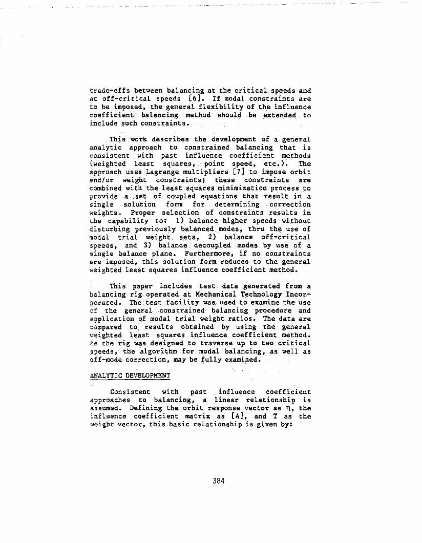
This paper includes test data generated from a balancing rig operated at Mechanical Technology Incor- porated. The test facility was used to examine the use of the general constrained balancing procedure and application of modal trial weight ratios. The data are compared to results obtained by using the general weighted least squares influence coefficient method. As the rig was designed to traverse up to two critical speeds, the algorithm for modal balancing, as well as off-mode correction, may be fully examined.
MALYTIC DEVELOPMENT
Consistent with past influence coefficient approaches to balancing, a linear relationship is assumed. Defining the orbit response vector as q, the influence coefficient matrix as [A], and T as the %#eight vector, this basic relationship is given by:
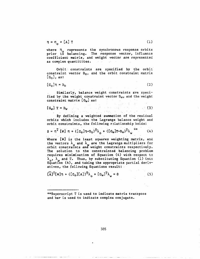
where T)O represents the synchronous response orbits prior to balancing. The response vector, influence coefficient matrix, and weight vector are represented as complex quantitites.
Orbit constraints are specified by the orbit constraint vector Do, and the orbit constraint matrix [Go], as:
[Go117 = Do ( 2 )
Similarly, balance weight constraints are speci- fied by the weight constraint vector Dw, and the weight constraint matrix [ G ~ I as:
EG,I T = Dw ( 3 )
By defining a weighted summation of the residual orbits which includes the Lagrange balance weight and orbit constraints, the following r3lationship holds:
* S = nT [w] Yl + ( [ G ~ I ~ ~ - D ~ ~ ~ A ~ + ([G~IT-D~)~A~ ( 4 )
Where [w] is the least squares weighting matrix, and the vectors AD and A are the Lagrange multipliers for orbit constramts an3 weight constraints respectively. The solution to the constrainted balancing problem requires minimization of Equation (4) with respect to
A and T. Thus, by substituting Equation 41) into lo' w Equatlon (41, and taking the appropriate partial deriv- atives, the following Equations result:
*Superscript T is used to indicate matrix transpose and bar is used to indicate complex conjugate.
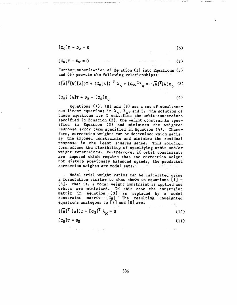
Further substitution of Equation (1) into Equations (5) and ( 6 ) provide the following relationships:
Equations (71 , (8) and (9). are a set of simultane- ous linear equations in Xo., AH, and T. The solution of these equations for T satisfies the orbit constraints specified in Equation (21, the weight constraints spec- ified in Equation ( 3 ) and minimizes the weighted response error term specified in Equation ( 4 ) . There- fore, correction weights can be determined which satis- fy the imposed constraints and minimize the residual response in the least squares sense. This solution form offers the flexibility of specifying orbit and/or weight constraints. Furthermore, if orbit constraints are imposed which require that the correction weight not disturb previously balanced speeds, the predicted correction weights are modal sets.
Modal trial weight ratios can be calculated using a formulation similar to that shown in equations [I] - [6]. That is, a modal weight constraint is applied and orbits are minimized. In this case the constraint: matrix in equation [3] is replaced by a modal constraint matrix [GM] The resulting unweighted equations analogous to [7] and [ 8 ] are:
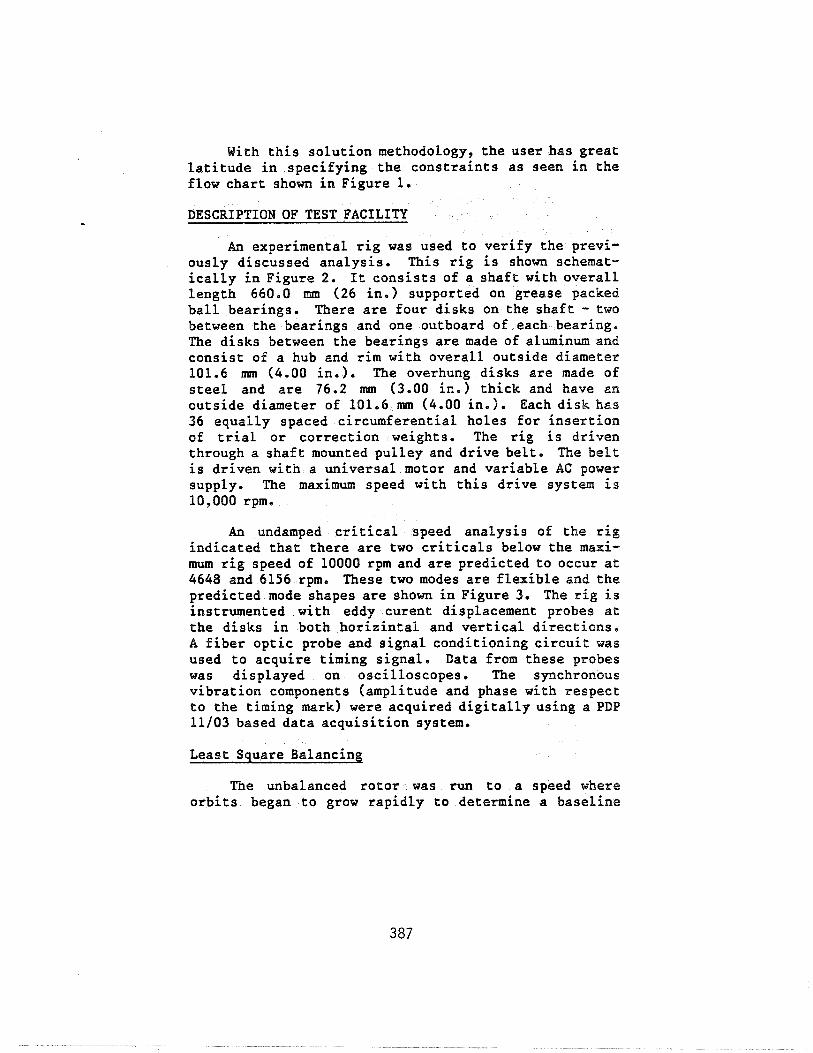
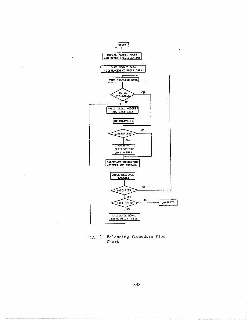
With this solution methodology, the user has great latitude in specifying the constraints as seen in the flow chart shown in Figure 1.
DESCRIPTION OF TEST FACILITY
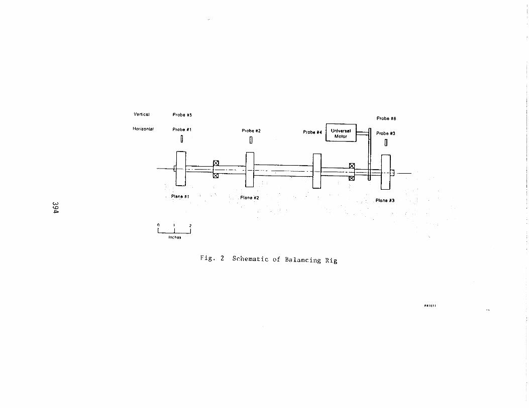
An experimental rig was used to verify the previ- ously discussed analysis. This rig is shown schemat- ically in Figure 2. It consists of a shaft with overall length 660.0 mm (26 in.) supported on grease packed ball bearings. There are four disks on the shaft - two between the bearings and one outboard of each bearing. The disks between the bearings are made of aluminum and consist of a hub and rim with overall outside diameter 101.6 mm (4.00 ino 1. The overhung disks are made of steel and are 76.2 mm (3.00 in.) thick and have an outside diameter of 101.6 mm (4.00 in.). Each disk has 36 equally spaced circumferential holes for insertion of trial or correction weights. The rig is driven through a shaft mounted pulley and drive belt. The belt is driven with a universal motor and variable AC power supply. The maximum speed with this drive system is 10,000 rpm.
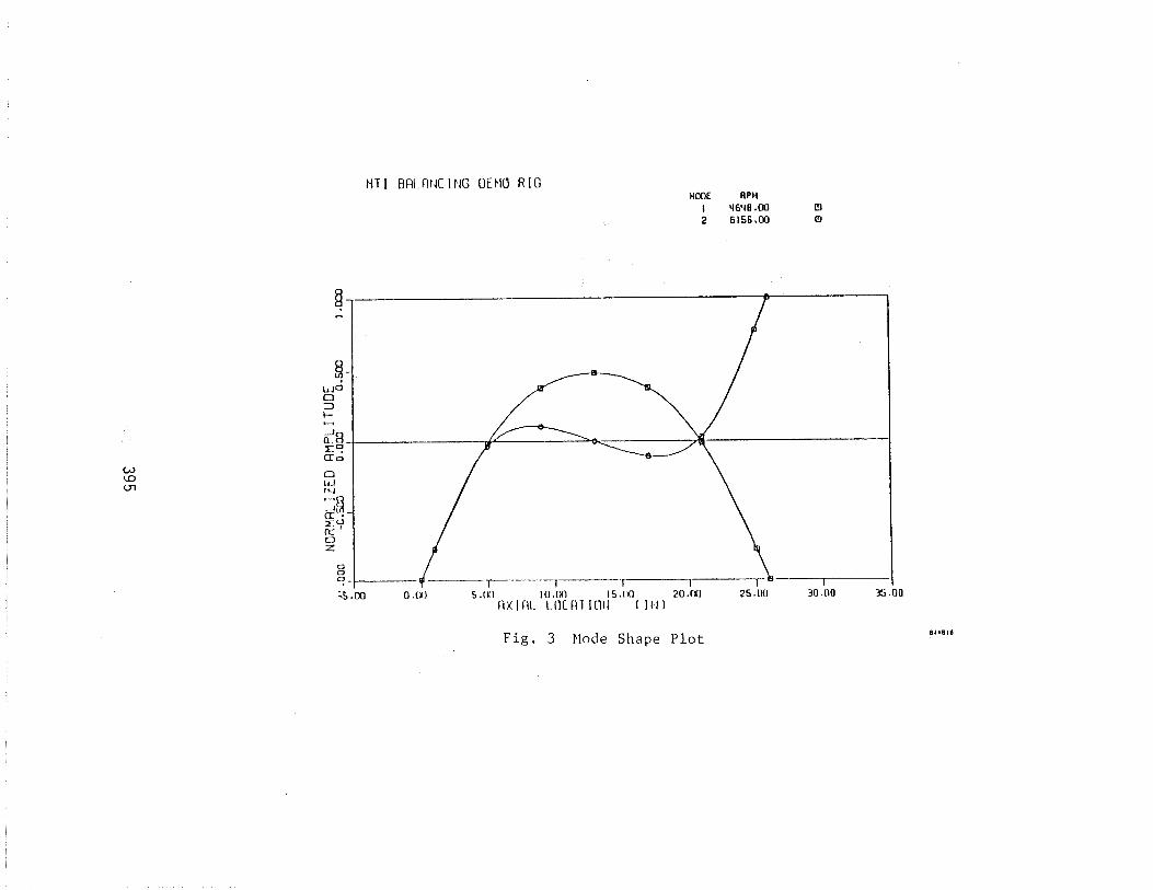
An undamped critical speed analysis of the rig indicated that there are two criticals below the maxi- mum rig speed of 10000 rpm and are predicted to occur at 4648 and 6156 rpm. These two modes are flexible and the predicted mode shapes are shown in Figure 30 The rig is instrumented with eddy curent displacement probes at the disks in both horizintal and vertical directions. A fiber optic probe and signal conditioning circuit was used to acquire timing signal. Data from these probes was displayed on oscilloscopes. The synchronous vibration components (amplitude and phase with respect to the timing mark) were acquired digitally using a PDP 11/03 based data acquisition system.
Least Square Balancing
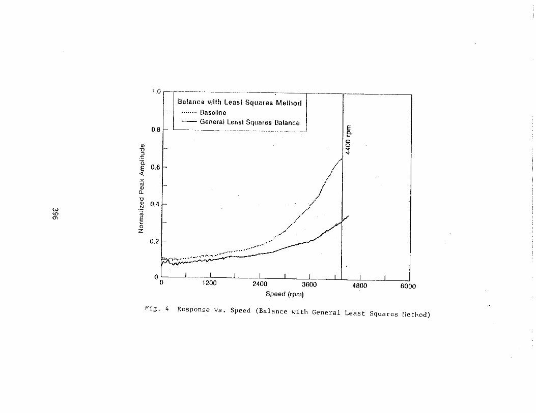
The unbalanced rotor was run to a speed where orbits began to grow rapidly to determine a baseline
-balanced conditicm. The resulting response is shown in Figure 4 for probe #I. I)ue to excessive vibration, it was not possible to exceed 4400 rpm. From this base- line condition, 4400 rpm was chosen as the balancing speed, Using the general least square influence coef- ficient method, the rotor was balanced as shown in Figure 4.
Constraint Balancing
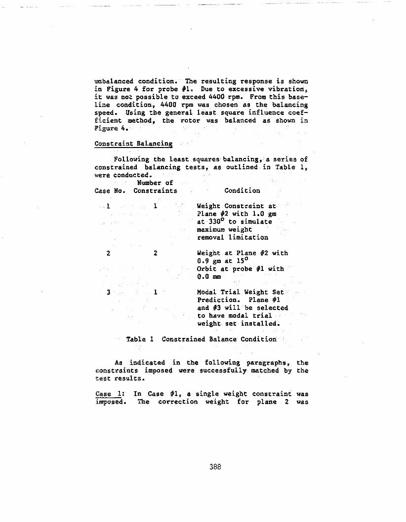
Following the Least squares balancing, a series of constrained balancing tests, as outlined in Table 1, were conducted.
Nmber of Case lo. Constraints Condition
1 1 Weight Constraint at Plane #2 with 1.0 gm at 330' to simulate maximum weight removal limitation
2 2 Weight at Plane %2 with 0.9 gm at lsO Orbit at probe Xl with 0.0 IIlm
3 1 Modal Trial Weight Set Prediction. Plane #l and %3 will be selected to have modal trial weight set installed.
Table 1 Constrained Balance Condition
As indicated in the following paragraphs, the constraints imposed were successfully lnatched by the test results.
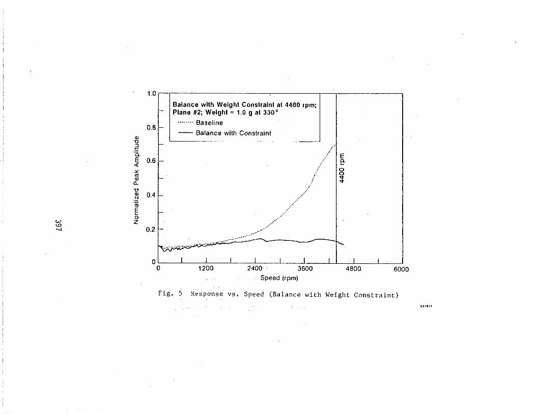
Case I: In Case X1, a single weight constraint was imposed. The correction weight for plane 2 was
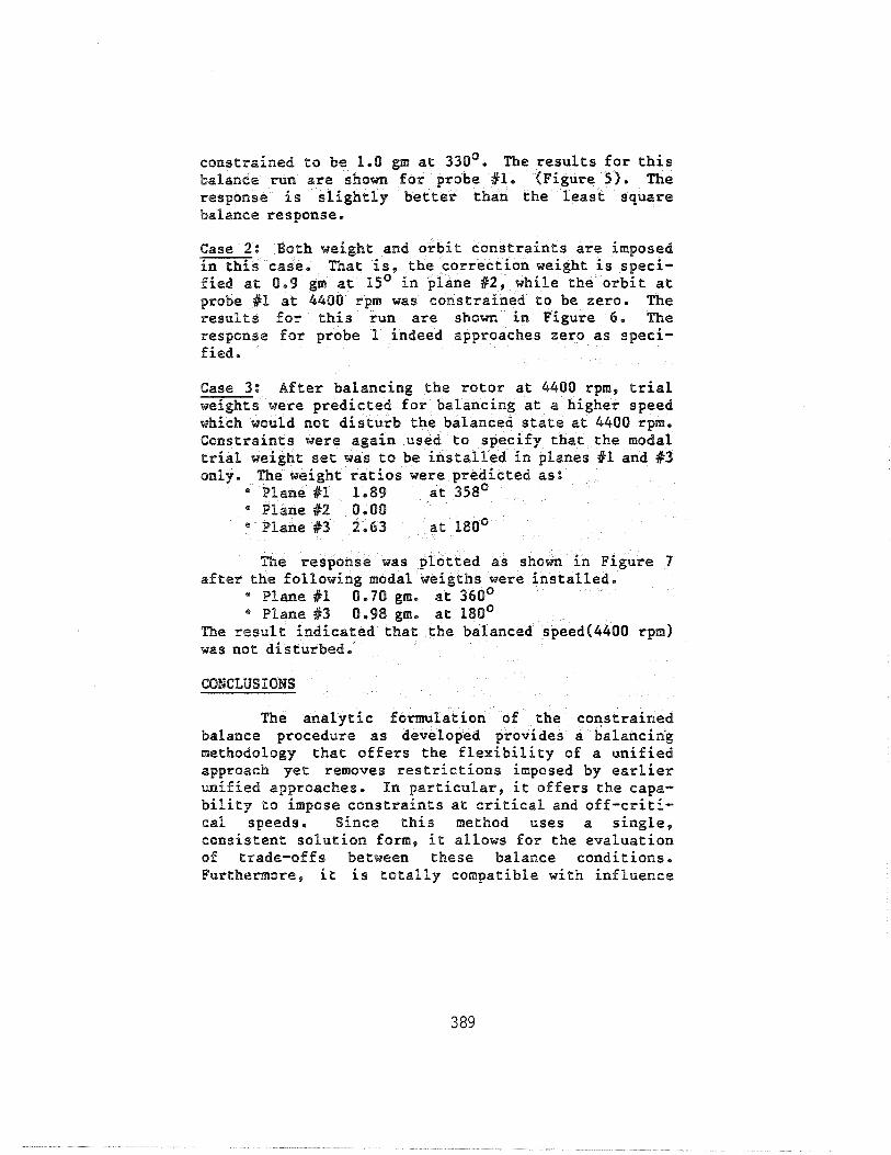
constrained to be 1.0 gm at 330'. The results for this balance run are shown for probe #1. (Figure 5 ) . The response is slightly better than the least square balance response.
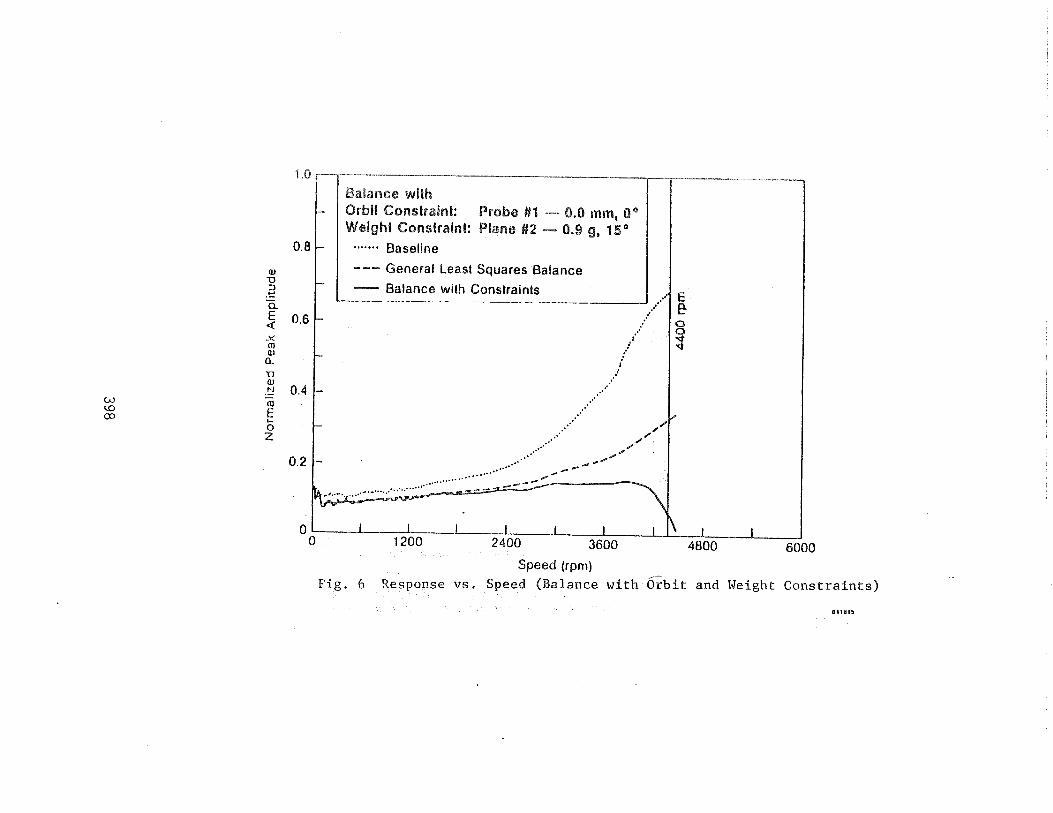
Gase 2: Both weight and orbit constraints are imposed in this case. That is, the correction weight is speci- fied at 0.9 gm at 15' in plane #2, while the orbit at probe 81 at 4400 rpm was constrained to be zero. The results for this run are shown in Figure 6. The response for probe 1 indeed approaches zero as speci- fied.
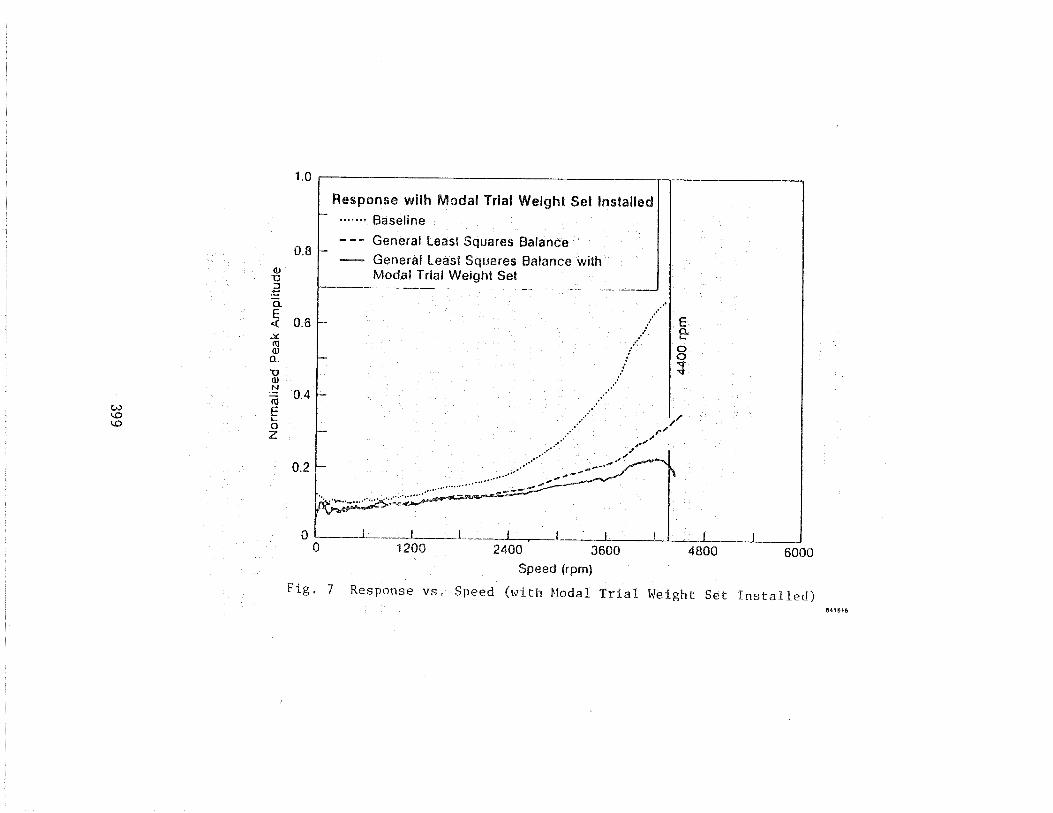
Gase 3: After balancing the rotor at 4400 rpm, trial weights were predicted for balancing at a higher speed which would not disturb the balanced state at 4400 rpm. Constraints were again used to specify that the modal trial weight set was to be installed in planes #1 and 83 only. The weight ratios were predicted as:
* Plane 81 1.89 at 358' * Planef2 0.00 " Plane 113 2.63 at 180'
The response was plotted as shown in Figure 7 after the following modal weigths were installed.
" Plane 81 0.70 gm. at 360' * Plane #3 0,98 gm. at 180'
The result indicated that the balanced speed(4400 rpm) was not disturbed.
CONCLUSIONS
The analytic formulation of the constrained balance procedure as developed provides a balancin'g methodology that offers the flexibility of a unified approach yet removes restrictions imposed by earlier unified approaches. In particular, it offers the capa- bility to impose constraints at critical and off-criti- cal speeds. Since this method uses a single, consistent solution form, it allows for the evaluation of trade-offs between these balance conditions. Furthermore, it is totally compatible with influence
coefficient methods and, in fact, reduces to the gener- al weighted least squares solltltion when constraints are eliminated,
No limitations for detemining the influence coefficients are imposed. Accordingly, using "modal" trial weight sets and/or redefining influence coef f i- cients to be consistent with modal sets is possible, merefore, one may use the full capabilities of modal weight sets for determing influence coefficients and directly integrate these results with the constrained balancing algorith.
The test data has verified that this method offers a viable approach to balancing high-speed rotors; it also offers a great deal of flexibility to engineers when confronted with difficulties coman to balancing rotating makhinery, For example, orbits can be specified at any speed, to allow for smooth machine operation at the design operating speeds, control of bearing loads, etc, Balance weights can also be sgeci- f ied to compensate for balance planes which cannot aceornodate more correction weight addition or removal, Furthermore, combinations of these types of constraints can be irnposed simultaneously,
Application of modal trial weight sets will not affect the lower speeds that have already been balanced. This practice is especially useful when rotors are very sensitive to imbalance. In fact, the application of modal trial weight set can reduce the nunnber of trial weight runs since the! set will not disturb those balanced lower modes.
The authors gratefully acknowledge the assist- ance of Mr. James Walton of Mechanical Technology Incorporated for his valuable suggestions and contrib- ution and Mr. David Smith in providing the PDP11/0% computer based data acquisition system for use in this study.
1. Bishop, R.E.D., and Gladwell, G.M,L,, he Vibration and Balancing of an Unbalanced Flex- ible Rotor" , ~ournal of Mechanical Engineering Science, Vol. 1, No. 1, 1959, pp. 66-77.
2, Goodman, T.P., "A Least-Squares Method for Computing Balance ~orrections", Journal of Engineering for Industry, Trans. ASME, Series B, Vole 86, No, 3, August 1964.
1 @ 3. Zorzi, E.S., and Fleming, D., Balancing of a Power-Transmission Shaft with Axial Torque"", ASME 80-GT-143, March 1980,
4 . Darlow, M.S., "A Unified Approach to the Mass Balancing of Rotating Flexible Shafts", PhD, Dissertation, University of Florida, 1980.
5. Parkinson, A.G,, Darlow, M.S., Smalley, A.J., and Badgley, R.W., "An Introduction to a Unified Approach to Flexible Rotor ~alancing"", ASME paper presented at the ASME Gas Turbine Conference, March 1979,
6, Zorzi, E.S., Giordano, J.C., and Lee, C.C,, "'A Unified Approach to Balancing with Multiple Constraints", IFTOM Conference on Rotordy- namic Problems in Power Plants, Sept. 28 - Oct, 2, 1982, Rome, Italy*
7. Weinstock, R., Calculus of Variations, McGraw-Hill, 1952.
8. Tessarzik, J.M., Badgley, R.H., and Anderson, W.J., "Flexible Rotor Balancing by the Exact Point-Speed Influence Coefficient Method", Journal of Engineering for Industry, Vol, 94, No. 1, pp. 148-158, February 1972.
TAKE BASELINE DATA !77
APPLY TRIAL WEIGHTS IWTU" 1 CALCULATE IC LFl--- CONSTRAINTS
1 CONSTRAINTS 1 I - 1
Fig. 1 aalancing Procedure Flow Chart