WIRING DIAGRAMS 0foorumiliitteet.s3.amazonaws.com/2016/11/1143_57fc... · hal. = halogen WIRING...
28
Section 11 WIRING DIAGRAMS Subsection 01 (WIRING DIAGRAMS) MMR2000_111_11_01A.FM 11-01-1 WIRING DIAGRAMS 0 hal. = halogen WIRING DIAGRAM LEGEND 1. Wire colors 2. Connector housing area 3. Housing number per area 4. Wire connector location in housing WIRE COLORS The first color of a wire is the main color, second color is the stripe. Example: YL/BK is a YELLOW wire with a BLACK stripe. CONNECTOR HOUSING AREA MODELS WIRING DIAGRAM PAGE HEADLIGHT (watt) TAILLIGHT (watt) ELECTRICAL SYSTEM OUTPUT (watt) Grand Touring 600 Annex 1 60/55 hal. 8/27 290 MX Z 500/500 (SB)/600/700 Formula Z 600/700 Annex 2 60/55 hal. 8/27 290 Formula DLX 600/700 Annex 3 60/55 hal. 8/27 290 MX Z 600 (DPM)/700 (DPM) Summit 600/600 (SB)/700/ 700 (SB)/700 H.M. Annex 4 60/55 hal. 8/27 290 m WARNING Ensure all terminals are properly crimped on the wires and all connector housings are prop- erly fastened. A00I04E XX/XX 1 - MC 1 2 3 4 D 1- MC D A00I04F XX/XX XX/XX COLOR CODE BE – BEIGE BK – BLACK BL – BLUE BR – BROWN GN – GREEN GY – GREY OR – ORANGE RD – RED VI – VIOLET WH – WHITE YL – YELLOW - MC D XX/XX A00I04G 1 1
Transcript of WIRING DIAGRAMS 0foorumiliitteet.s3.amazonaws.com/2016/11/1143_57fc... · hal. = halogen WIRING...
Section 11 WIRING DIAGRAMSSubsection 01 (WIRING DIAGRAMS)
MMR2000_111_11_01A.FM 11-01-1
WIRING DIAGRAMS 0
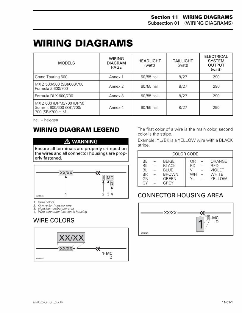
hal. = halogen
WIRING DIAGRAM LEGEND
1. Wire colors2. Connector housing area3. Housing number per area4. Wire connector location in housing
WIRE COLORS
The first color of a wire is the main color, secondcolor is the stripe.Example: YL/BK is a YELLOW wire with a BLACKstripe.
CONNECTOR HOUSING AREA
MODELSWIRING
DIAGRAMPAGE
HEADLIGHT(watt)
TAILLIGHT(watt)
ELECTRICALSYSTEMOUTPUT
(watt)
Grand Touring 600 Annex 1 60/55 hal. 8/27 290
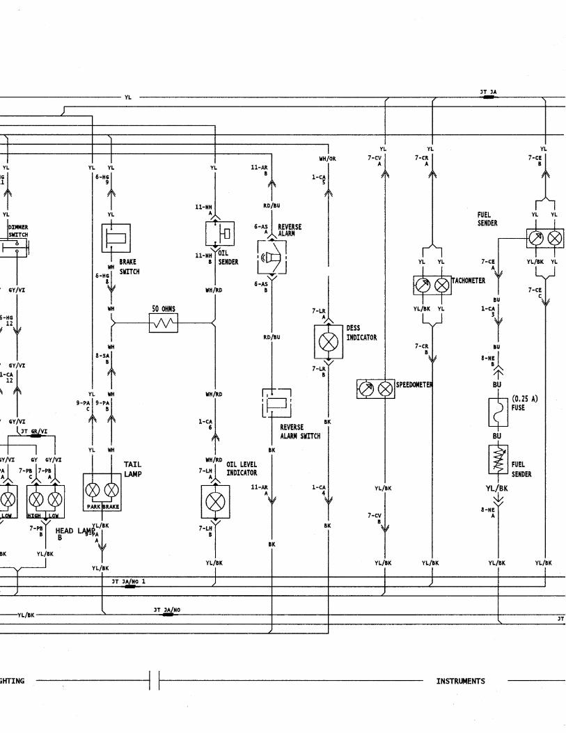
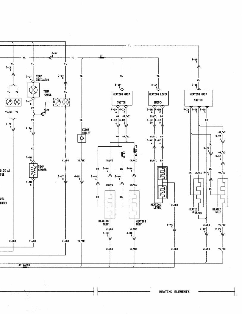
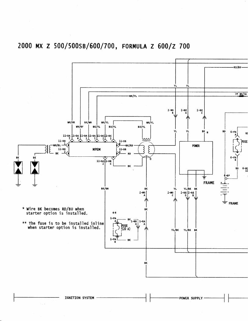
MX Z 500/500 (SB)/600/700Formula Z 600/700 Annex 2 60/55 hal. 8/27 290
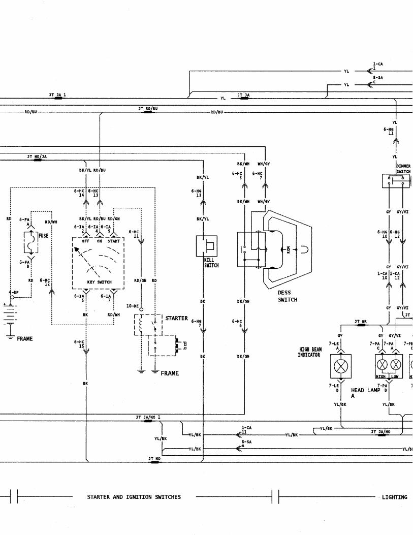
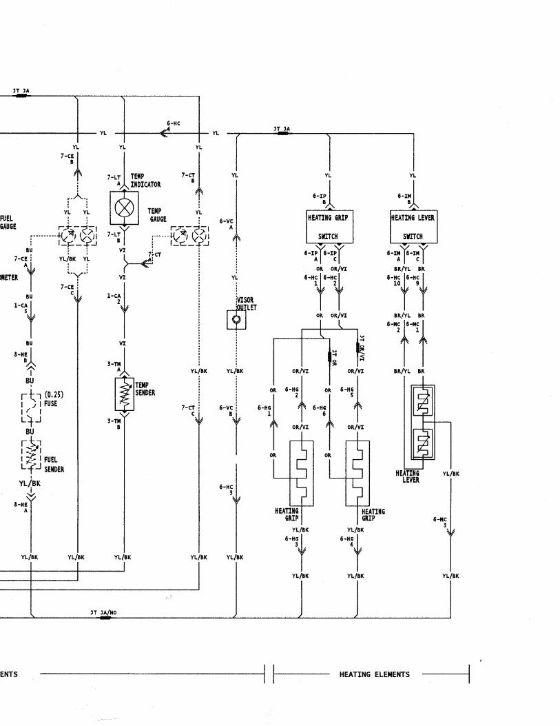
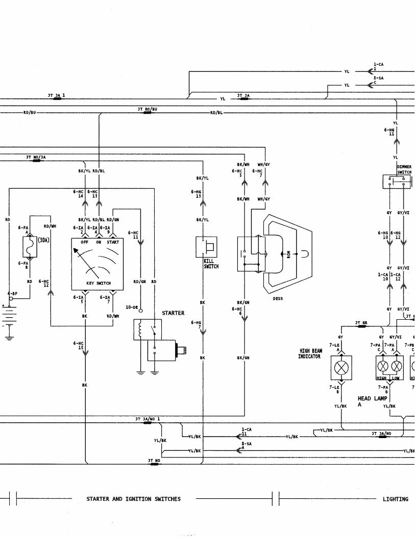
Formula DLX 600/700 Annex 3 60/55 hal. 8/27 290
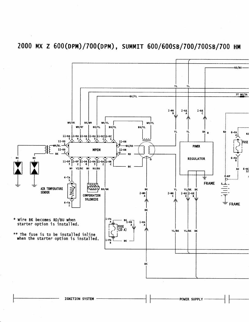
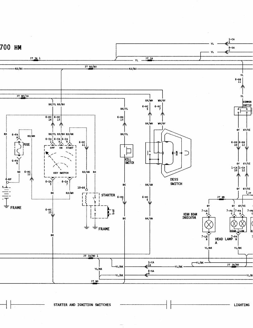
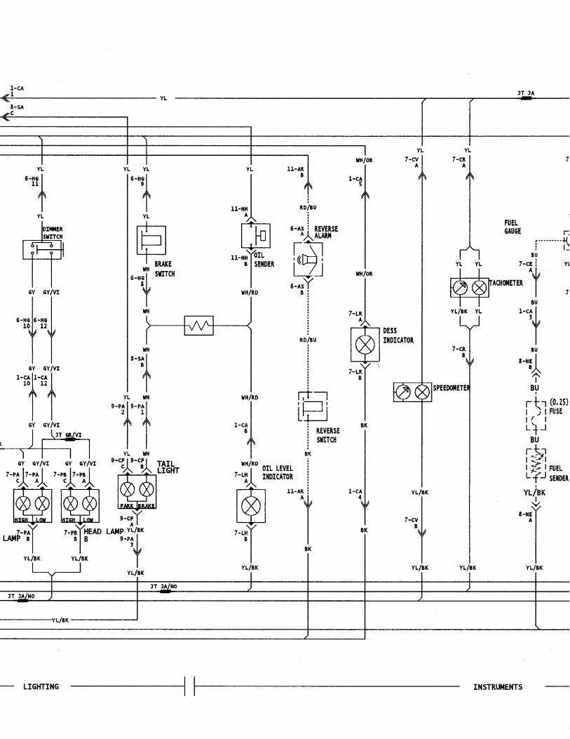
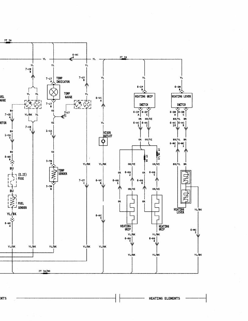
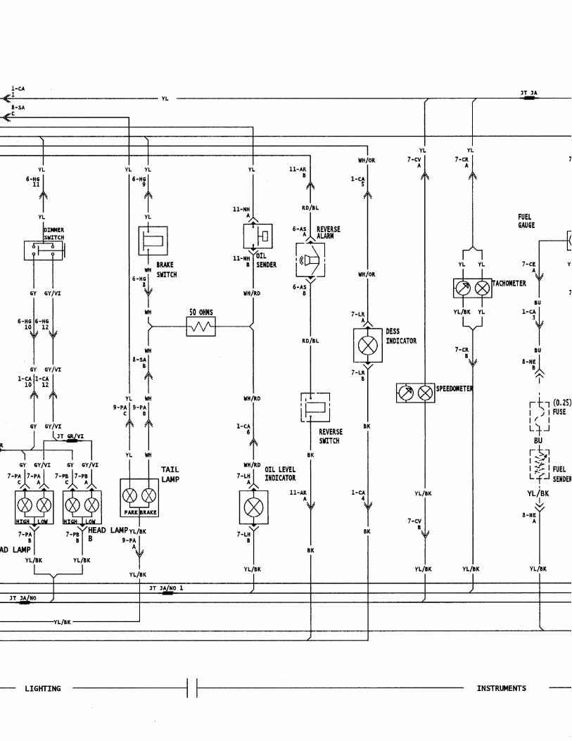
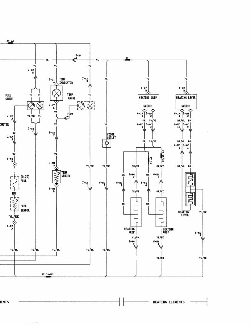
MX Z 600 (DPM)/700 (DPM)Summit 600/600 (SB)/700/700 (SB)/700 H.M.
Annex 4 60/55 hal. 8/27 290
m WARNING
Ensure all terminals are properly crimped onthe wires and all connector housings are prop-erly fastened.
A00I04E
XX/XX1 - MC
1 2 3 4
D
1- MCDA00I04F
XX/XX
XX/XX
COLOR CODE
BE – BEIGEBK – BLACKBL – BLUEBR – BROWNGN – GREENGY – GREY
OR – ORANGERD – REDVI – VIOLETWH – WHITEYL – YELLOW
- MCD
XX/XX
A00I04G
11
1
Section 11 WIRING DIAGRAMSSubsection 01 (WIRING DIAGRAMS)
11-01-2 MMR2000_111_11_01A.FM
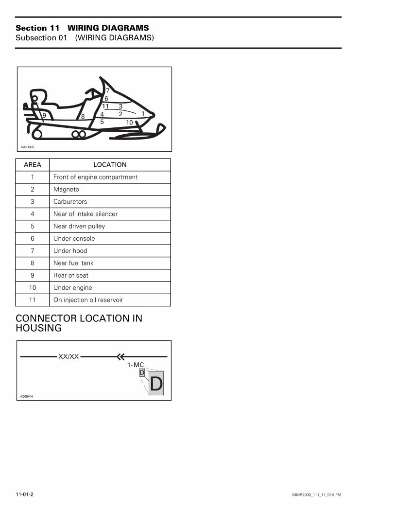
CONNECTOR LOCATION IN HOUSING
AREA LOCATION
1 Front of engine compartment
2 Magneto
3 Carburetors
4 Near of intake silencer
5 Near driven pulley
6 Under console
7 Under hood
8 Near fuel tank
9 Rear of seat
10 Under engine
11 On injection oil reservoir
A06H33C
1
76
9 8 45
32
10
11
XX/XX
A00I04H
D
D1- MC
Section 11 WIRING DIAGRAMSSubsection 01 (WIRING DIAGRAMS)
MMR2000_111_11_01A.FM 11-01-3
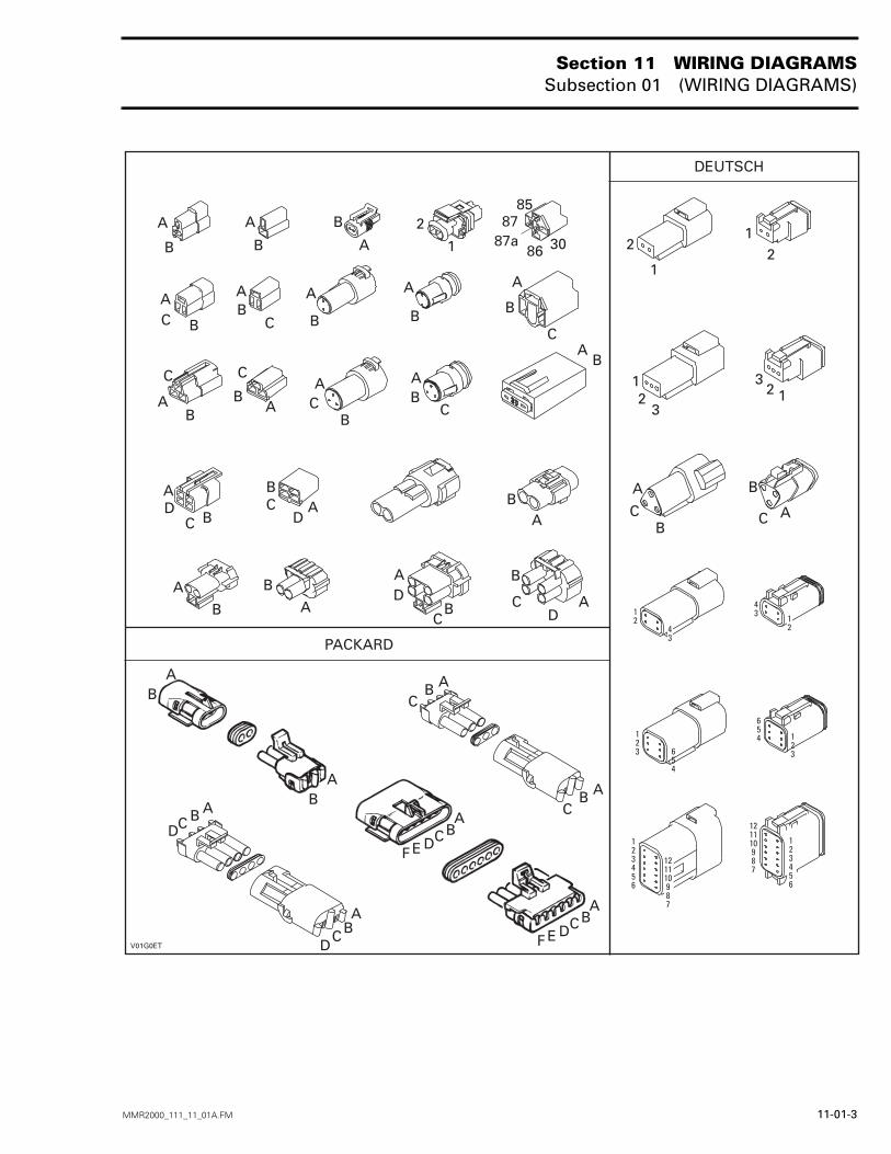
V01G0ET
DEUTSCH
21
123
3
A
CB
AC
B
123456
121110987
121110987
123456
123 6
54
123
654
12
43
43
12
2
1
12
A
B
A
B
B
A2
1
8587
308687a
A
BC
AB
C
A
B
AC
B
A
B
AB
C
AB
C
A
B
BA
AB
C
AD
C B
BC A
D
AB
AD
CB
A
B
C
A
B
PACKARD
BA
BA
B AC
B ACB A
CD
BA
CD
ABCDEF
B
CD
A
ABCDEF
Section 11 WIRING DIAGRAMSSubsection 01 (WIRING DIAGRAMS)
11-01-4 MMR2000_111_11_01A.FM
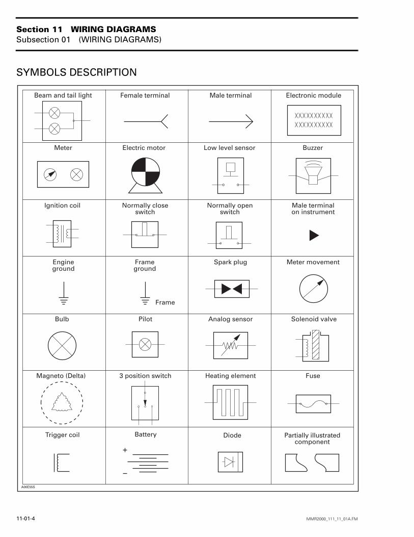
SYMBOLS DESCRIPTION
Beam and tail light Female terminal Male terminal Electronic module
Meter Electric motor Low level sensor Buzzer
Ignition coil Normally closeswitch
Male terminalon instrument
Engineground
Spark plug Meter movement
Bulb Pilot Analog sensor Solenoid valve
Magneto (Delta) 3 position switch Heating element Fuse
Normally openswitch
Frameground
Frame
Trigger coil Battery Diode Partially illustratedcomponent
A00E55S
Section 11 WIRING DIAGRAMSSubsection 01 (WIRING DIAGRAMS)
MMR2000_111_11_01A.FM 11-01-5
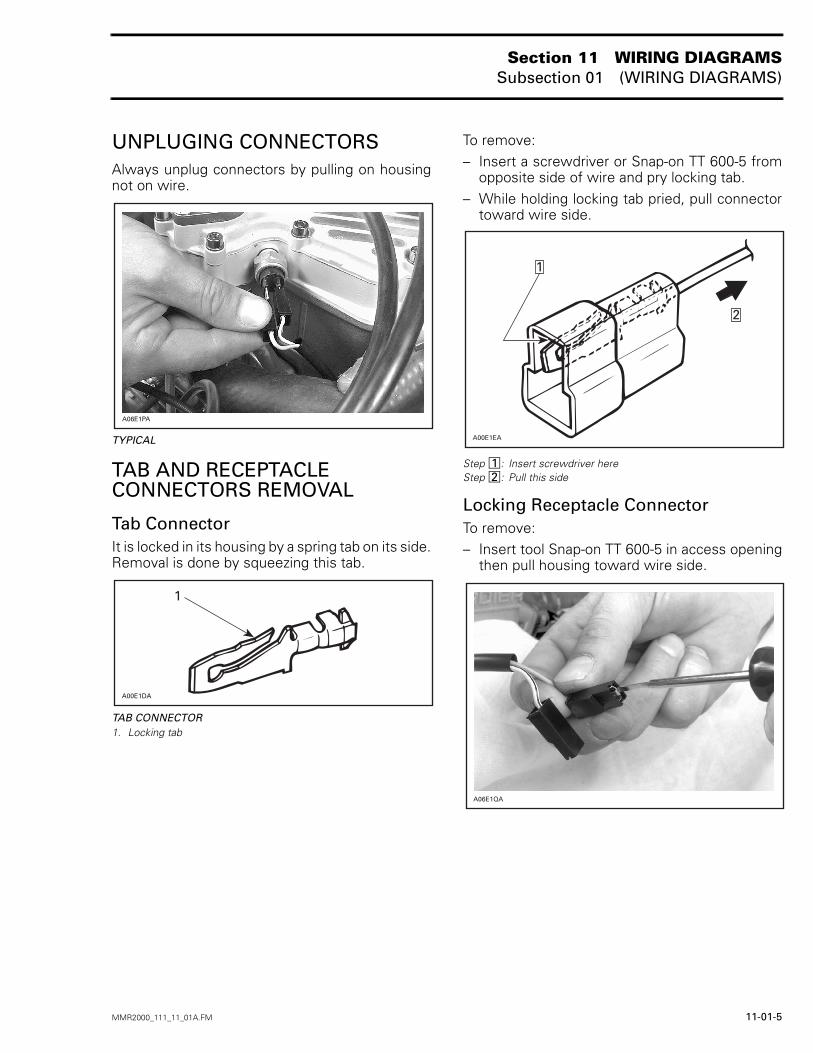
UNPLUGING CONNECTORSAlways unplug connectors by pulling on housingnot on wire.
TYPICAL
TAB AND RECEPTACLE CONNECTORS REMOVAL
Tab ConnectorIt is locked in its housing by a spring tab on its side.Removal is done by squeezing this tab.
TAB CONNECTOR1. Locking tab
To remove:– Insert a screwdriver or Snap-on TT 600-5 from
opposite side of wire and pry locking tab.– While holding locking tab pried, pull connector
toward wire side.
Step : Insert screwdriver hereStep : Pull this side
Locking Receptacle ConnectorTo remove:– Insert tool Snap-on TT 600-5 in access opening
then pull housing toward wire side.
A06E1PA
A00E1DA
1
A00E1EA
2
1
12
A06E1QA
Section 11 WIRING DIAGRAMSSubsection 01 (WIRING DIAGRAMS)
11-01-6 MMR2000_111_11_01A.FM
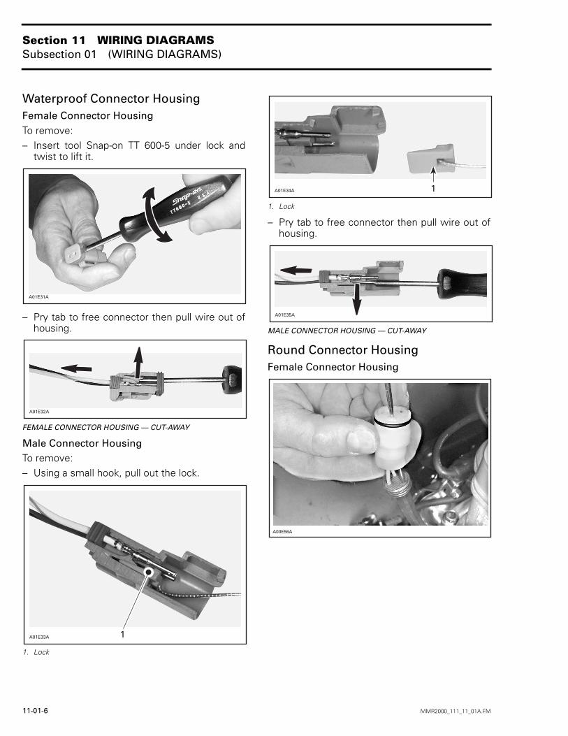
Waterproof Connector HousingFemale Connector HousingTo remove:– Insert tool Snap-on TT 600-5 under lock and
twist to lift it.
– Pry tab to free connector then pull wire out ofhousing.
FEMALE CONNECTOR HOUSING — CUT-AWAY
Male Connector HousingTo remove:– Using a small hook, pull out the lock.
1. Lock
1. Lock
– Pry tab to free connector then pull wire out ofhousing.
MALE CONNECTOR HOUSING — CUT-AWAY
Round Connector HousingFemale Connector Housing
A01E31A
A01E32A
A01E33A 1
A01E34A 1
A01E35A
A00E56A
Section 11 WIRING DIAGRAMSSubsection 01 (WIRING DIAGRAMS)
MMR2000_111_11_01A.FM 11-01-7
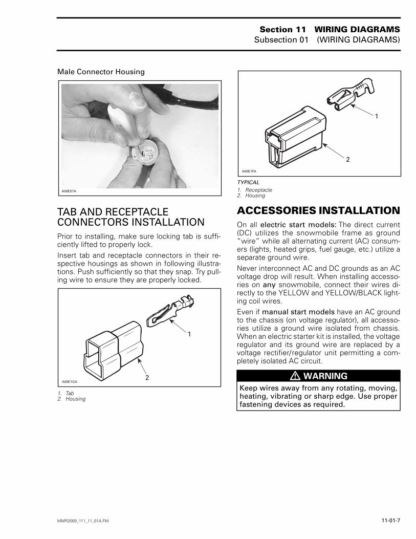
Male Connector Housing
TAB AND RECEPTACLE CONNECTORS INSTALLATIONPrior to installing, make sure locking tab is suffi-ciently lifted to properly lock.Insert tab and receptacle connectors in their re-spective housings as shown in following illustra-tions. Push sufficiently so that they snap. Try pull-ing wire to ensure they are properly locked.
1. Tab2. Housing
TYPICAL1. Receptacle2. Housing
ACCESSORIES INSTALLATIONOn all electric start models: The direct current(DC) utilizes the snowmobile frame as ground“wire” while all alternating current (AC) consum-ers (lights, heated grips, fuel gauge, etc.) utilize aseparate ground wire.Never interconnect AC and DC grounds as an ACvoltage drop will result. When installing accesso-ries on any snowmobile, connect their wires di-rectly to the YELLOW and YELLOW/BLACK light-ing coil wires.Even if manual start models have an AC groundto the chassis (on voltage regulator), all accesso-ries utilize a ground wire isolated from chassis.When an electric starter kit is installed, the voltageregulator and its ground wire are replaced by avoltage rectifier/regulator unit permitting a com-pletely isolated AC circuit.
A00E57A
A00E1GA
1
2 m WARNING
Keep wires away from any rotating, moving,heating, vibrating or sharp edge. Use properfastening devices as required.
A00E1FA
1
2
GR
AN
D T
OU
RIN
G 6
00
AN
NE
X 1
MX
Z 5
00
/50
0 (S
B)/6
00
/70
0FO
RM
ULA
Z 6
00
/70
0A
NN
EX
2

FOR
MU
LA D
LX 6
00
/70
0A
NN
EX
3

MX
Z 6
00 (D
PM
)/700 (D
PM
)S
UM
MIT
600/6
00 (S
B)/7
00/
700 (S
B)/7
00 H
.M.
AN
NE
X 4