WiRing - Legrand · 347 EX2014-2015 EP2 WEATHERPROOF WiRing Acc EssORiEs & OTHER insTAllATiOn...
26
347 WEATHERPROOF WIRING ACCESSORIES & OTHER INSTALLATION EQUIPMENT Weatherproof wiring accessories & boxes Plugs and multi-outlet extensions Installation equipment & connection P. 349 Plexo IP 55 complete flush-mounting P. 356 Plexo 66 flush and surface- mounting P. 363 Plastic industrial boxes P. 368 British standard plugs, travel adaptors P. 369 Chimes and bells Door entry system & detection NEW PRODUCTS 2014 NEW Chimes and bells (p. 369) Shaverlight Incandescent - british standard (p. 369)
Transcript of WiRing - Legrand · 347 EX2014-2015 EP2 WEATHERPROOF WiRing Acc EssORiEs & OTHER insTAllATiOn...

347
EX2014-2015EP2
WEATHERPROOF WiRingAccEssORiEs & OTHERinsTAllATiOn EquiPmEnT
Weatherproofwiring accessories & boxes
Plugs andmulti-outlet extensions
installationequipment& connection
P. 349Plexo IP 55completeflush-mounting
P. 356Plexo 66flush and surface-mounting
P. 363Plasticindustrialboxes
P. 368British standardplugs, travel adaptors
P. 369Chimesand bells
Door entry system& detection
NEW PRODUCTS 2014
nEW
chimes and bells(p. 369)
shaverlightIncandescent -british standard(p. 369)

348
P. 351Plexo IP 55mechanisms
P. 354Plexo IP 55boxes andsupport frames
P. 357Plexo boxes
colour videodoor entry kits7" and 3.5" colourvideo kits - 2 wires(p. 370)
P. 365Flush-mountingboxes
P. 370Colour videodoor entry kits
P. 371Audio doorentry kits
P. 350Plexo IP 55completesurface-mounting
P. 367Nylbloc connection terminals and strips
nEW
P. 355Green'up Accesssockets for electric vehicles
P. 369Shaverlight
nEW
P. 362Isolator switches
349
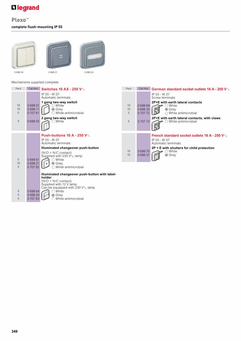
Plexo™
complete flush-mounting IP 55
Mechanisms supplied complete
Pack Cat.Nos Switches 10 AX - 250 VAIP 55 - IK 07Automatic terminals
1 gang two-way switch10 0 698 51 White10 0 698 11 Grey5 0 707 61 White antimicrobial
2 gang two-way switch5 0 698 55 White
Push-buttons 10 A - 250 VAIP 55 - IK 07Automatic terminals
Illuminated changeover push-button
(N/O + N/C contact)Supplied with 230 VA lamp
5 0 698 61 White10 0 698 21 Grey5 0 707 82 White antimicrobial
Illuminated changeover push-button with label-holder(N/O + N/C contact)Supplied with 12 V lampCan be equipped with 230 VA lamp
5 0 698 64 White5 0 698 24 Grey5 0 707 83 White antimicrobial
0 698 240 698 55 0 698 21
Pack Cat.Nos German standard socket outlets 16 A - 250 VAIP 55 - IK 07Screw terminals
2P+E with earth lateral contacts10 0 698 69 White10 0 698 33 Grey5 0 707 72 White antimicrobial
2P+E with earth lateral contacts, with claws5 0 707 73 White antimicrobial
French standard socket outlets 16 A - 250 VAIP 55 - IK 07Automatic terminals
2P + E with shutters for child protection10 0 698 70 White10 0 698 31 Grey

350
Plexo™
complete surface-mounting IP 55
0 697 11 0 697 12 0 697 39
Pack Cat.Nos Switches 10 AX - 250 VAIP 55 – IK 07Automatic terminals
Grey10 0 697 11 Two-way switch5 0 697 16 Intermediate switch
10 0 697 12 Two-way switch with indicatorSupplied with 230 VA lamp
5 0 697 13 Illuminated two-way switchSupplied with 230 VA lamp
10 0 697 15 Two-gang two-way switch
1 0 697 17 Double pole switch
Push-buttons 10 AIP 55 – IK 07Automatic terminals
Grey10 0 697 20 N/O contact
10 0 697 22 Illuminated N/O contactSupplied with 230 VA lamp
Movement detectorsIP 55 - IK 04Automatic terminalsAllows control of a lighting device as soon as themovement is detectedMaximum load:- 2000 W for incandescent and halogen lamps230 VA and- 2000 W for ELV halogen lamps,- 1000 VA for fluorescent tubes and compactfluorescent lampsDetection range from 0 to 12 mDetection angle : 360°Coverage pattern adjustable during installationprocessTemporization between 12 s and 16 min.Dim. 90x90x85 mm
1 0 697 80 White1 0 697 40 Grey
Pack Cat.Nos Socket outlets
Grey
German standard 16 A – 250 VA10 0 697 33 2P+E with earth lateral contact
screw terminals
British standard 13 A – 250 VA10 0 697 32 2P+E with screw terminals
5 0 697 39 2 x 2P+E screw terminals
5 0 697 50 2P+E unswitched + switch screw terminals
French standard 16 A – 250 VA10 0 697 31 2P+E with shutters for child protection,
automatic terminals
Membrane glands50 0 919 14 Grey (RAL 7035)50 0 919 15 Grey (RAL 7035)
Lamp supplied

351
Plexo™ mechanismsswitches, push-buttons and automatic switches IP 55
Mechanisms supplied with cover plateInstallation with surface-mounting boxes or flush-mounting support frames (p. 354)Automatic terminals
0 695 250 695 13 0 695 00 0 695 02
Pack Cat.Nos Switches 10 AX - 250 VAIP 55 - IK 07
Two-way switch10 0 696 11 White10 0 695 11 Grey5 0 707 11 White antimicrobial5 0 695 21 Intermediate switch
Two-way switch with indicatorSupplied with 230 VA lamp
5 0 696 12 White10 0 695 12 Grey
Illuminated two-way switchSupplied with 230 VA lamp
5 0 696 13 White5 0 695 13 Grey
2 gang two-way switch10 0 695 25 Grey5 0 707 26 White antimicrobial
Double pole switch10 0 695 30 Grey5 0 707 27 White antimicrobial
Switches 16 A - 250 VAIP 55 - IK 07
Two-way switch5 0 695 23 Grey
Illuminated two-way switchSupplied with 230 VA lamp
1 0 695 24 Grey
Double pole switch1 0 695 27 Grey
Double pole switch with indicatorSupplied with 230 VA lamp
1 0 695 28 Grey
Pack Cat.Nos Push-buttons 10 A
IP 55 - IK 07
N/O contact10 0 695 40 Grey5 0 707 30 White antimicrobial
10 0 695 41 Changeover (N/O + N/C contact)
Illuminated N/O contactSupplied with 230 VA lamp
10 0 695 42 Grey5 0 707 32 White antimicrobial
Illuminated - N/O contact with label-holderSupplied with 12 V lamp
5 0 707 33 White antimicrobial
10 0 695 43 Can be equipped with 230 VAlamp
10 0 695 44 Illuminated changeover pushbutton (N/O + N/C contact), with label holderSupplied with 12 V lampCan be equipped with 230 VAlamp
Automatic switches 230 VAIP 55 - IK 07Maximum detection range: 8 m (adjustable)
Without neutral - 2-wire connectionCan be used instead of a 1 way switchNo additional wiring requiredOperates: 60 to 300 W incandescent and halogenlamps 230 V±Temporization: 6 s to 6 min.Detection angle: 130°Luminosity threshold: 3 to 1000 lux
1 0 695 00 Grey/White
With neutral - 3-wire connectionOperates:- 500 to 1000 W incandescent and halogen lamps230 VA- ELV halogen lamps- compact fluorescent lampeTemporization: 1 s to 16 min.Detection angle: 180°Luminosity threshold: 3 to 1000 lux
1 0 695 02 Grey/White
Lamp supplied
0 707 33
352
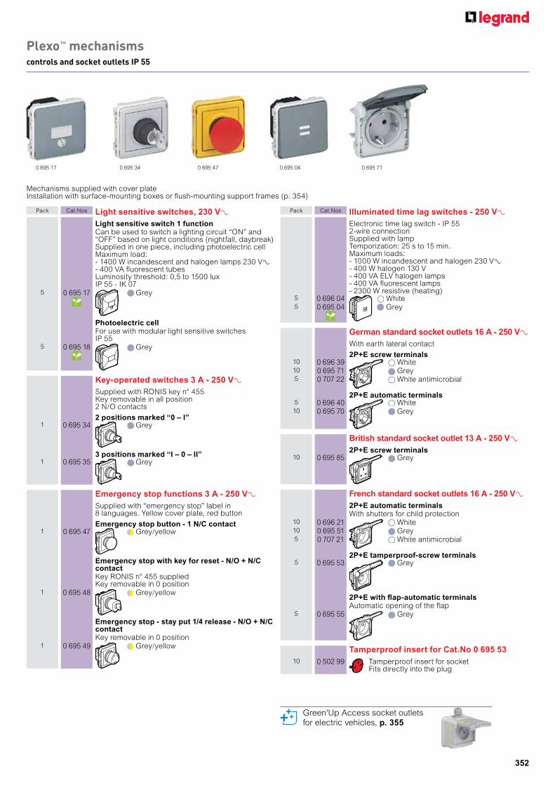
Plexo™ mechanismscontrols and socket outlets IP 55
0 695 34 0 695 47 0 695 71
Mechanisms supplied with cover plateInstallation with surface-mounting boxes or flush-mounting support frames (p. 354)
Pack Cat.Nos Switches 10 AX - 250 VAIP 55 - IK 07
Two-way switch10 0 696 11 White10 0 695 11 Grey5 0 707 11 White antimicrobial5 0 695 21 Intermediate switch
Two-way switch with indicatorSupplied with 230 VA lamp
5 0 696 12 White10 0 695 12 Grey
Illuminated two-way switchSupplied with 230 VA lamp
5 0 696 13 White5 0 695 13 Grey
2 gang two-way switch10 0 695 25 Grey5 0 707 26 White antimicrobial
Double pole switch10 0 695 30 Grey5 0 707 27 White antimicrobial
Switches 16 A - 250 VAIP 55 - IK 07
Two-way switch5 0 695 23 Grey
Illuminated two-way switchSupplied with 230 VA lamp
1 0 695 24 Grey
Double pole switch1 0 695 27 Grey
Double pole switch with indicatorSupplied with 230 VA lamp
1 0 695 28 Grey
Pack Cat.Nos Light sensitive switches, 230 VALight sensitive switch 1 functionCan be used to switch a lighting circuit “ON” and“OFF” based on light conditions (nightfall, daybreak)Supplied in one piece, including photoelectric cellMaximum load:- 1400 W incandescent and halogen lamps 230 VA- 400 VA fluorescent tubesLuminosity threshold: 0,5 to 1500 luxIP 55 - IK 07
5 0 695 17 Grey
Photoelectric cellFor use with modular light sensitive switchesIP 55
5 0 695 18 Grey
Key-operated switches 3 A - 250 VASupplied with RONIS key n° 455Key removable in all position2 N/O contacts
2 positions marked “0 – I”1 0 695 34 Grey
3 positions marked “I – 0 – II”1 0 695 35 Grey
Emergency stop functions 3 A - 250 VASupplied with “emergency stop” label in 8 languages. Yellow cover plate, red button
Emergency stop button - 1 N/C contact1 0 695 47 Grey/yellow
Emergency stop with key for reset - N/O + N/C contactKey RONIS n° 455 suppliedKey removable in 0 position
1 0 695 48 Grey/yellow
Emergency stop - stay put 1/4 release - N/O + N/C contactKey removable in 0 position
1 0 695 49 Grey/yellow
Pack Cat.Nos Illuminated time lag switches - 250 VAElectronic time lag switch - IP 552-wire connectionSupplied with lampTemporization: 25 s to 15 min.Maximum loads:- 1000 W incandescent and halogen 230 V±- 400 W halogen 130 V- 400 VA ELV halogen lamps- 400 VA fluorescent lamps- 2300 W resistive (heating)
5 0 696 04 White5 0 695 04 Grey
German standard socket outlets 16 A - 250 VAWith earth lateral contact
2P+E screw terminals10 0 696 39 White10 0 695 71 Grey5 0 707 22 White antimicrobial
2P+E automatic terminals5 0 696 40 White10 0 695 70 Grey
British standard socket outlet 13 A - 250 VA2P+E screw terminals
10 0 695 85 Grey
French standard socket outlets 16 A - 250 VA2P+E automatic terminalsWith shutters for child protection
10 0 696 21 White10 0 695 51 Grey5 0 707 21 White antimicrobial
2P+E tamperproof-screw terminals5 0 695 53 Grey
2P+E with flap-automatic terminalsAutomatic opening of the flap
5 0 695 55 Grey
Tamperproof insert for Cat.No 0 695 5310 0 502 99 Tamperproof insert for socket
Fits directly into the plug
Green'Up Access socket outlets for electric vehicles, p. 355
0 695 17 0 695 04
353
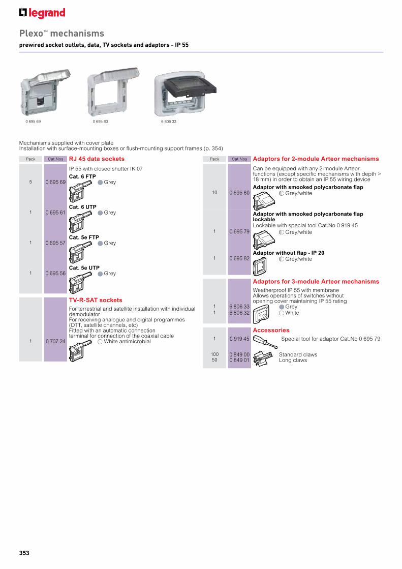
IP 55 with closed shutter IK 07
Cat. 6 FTP5 0 695 69 Grey
Cat. 6 UTP1 0 695 61 Grey
Cat. 5e FTP1 0 695 57 Grey
Cat. 5e UTP1 0 695 56 Grey
TV-R-SAT socketsFor terrestrial and satellite installation with individualdemodulatorFor receiving analogue and digital programmes(DTT, satellite channels, etc)Fitted with an automatic connectionterminal for connection of the coaxial cable
1 0 707 24 White antimicrobial
Plexo™ mechanismsprewired socket outlets, data, TV sockets and adaptors - IP 55
Mechanisms supplied with cover plateInstallation with surface-mounting boxes or flush-mounting support frames (p. 354)
0 695 69 0 695 80 6 806 33
Pack Cat.Nos RJ 45 data sockets Pack Cat.Nos Adaptors for 2-module Arteor mechanisms
Can be equipped with any 2-module Arteorfunctions (except specific mechanisms with depth >18 mm) in order to obtain an IP 55 wiring device
Adaptor with smooked polycarbonate flap10 0 695 80 Grey/white
Adaptor with smooked polycarbonate flap lockableLockable with special tool Cat.No 0 919 45
1 0 695 79 Grey/white
Adaptor without flap - IP 201 0 695 82 Grey/white
Adaptors for 3-module Arteor mechanismsWeatherproof IP 55 with membraneAllows operations of switches withoutopening cover maintaining IP 55 rating
1 6 806 33 Grey1 6 806 32 White
Accessories1 0 919 45 Special tool for adaptor Cat.No 0 695 79
100 0 849 00 Standard claws50 0 849 01 Long claws

354
Flush-mounting support framesUsed for flush-mounting version for Germanand French standard boxes only
1 gangCan be equipped with claws Cat.Nos 0 849 00/01
10 0 696 92 White10 0 696 81 Grey10 0 707 92 White antimicrobial
2 gang - 2 entries71 mm fixing centres
5 0 696 94 White - horizontal mounting5 0 696 83 Grey - horizontal mounting1 0 707 94 White antimicrobial - horizontal
mounting
Plexo™
surface-mounting boxes, support frames and accessories IP 55
To be equipped with modular Plexo mechanisms (p. 351-353)
0 696 51 0 696 68 0 696 92
Pack Cat.Nos Surface-mounting boxes with membrane glandsEquipped with removable membrane glandsDirect entry of cables (no need to be cut)
1 gang - 1 entry10 0 696 89 White10 0 696 51 Grey10 0 707 41 White antimicrobial
2 gang - 2 entriesNo separation between compartments, in order tofacilitate the cabling operations and to allow theinstallation of pre-wired socket outlets
5 0 696 90 White - horizontal mounting5 0 696 72 Grey - horizontal mounting1 0 707 42 White antimicrobial - horizontal
mounting
5 0 696 91 White - vertical mounting5 0 696 61 Grey - vertical mounting1 0 707 43 White antimicrobial - vertical mounting
Surface-mounting boxes for cable glands1 gang - 1 entry
5 0 696 56 Grey
2 gang - 2 entries (2 top)5 0 696 78 Grey - horizontal mounting
5 0 696 68 Grey - vertical mounting
Pack Cat.Nos Flush-mounting support frames (continued)
Used for flush-mounting version for Germanand French standard boxes only
2 gang - 2 entries71 mm fixing centres
5 0 696 96 White - vertical mounting5 0 696 85 Grey - vertical mounting1 0 707 49 White antimicrobial - vertical mounting
3 gang - 3 entries71 mm fixing centres
5 0 696 87 Grey - horizontal mounting
Flush-mounting boxes for allranges and standards, p. 356
0 696 72 0 696 96
Blanking plate5 0 695 37 To be used as needed in
combination with surfacemounting boxes or flush mountingframes
Cable outlets
IP 55 - IK 085 0 698 48 Cable outlet supplied with cable
grip Ø5 to 13 mm
LampsFor indicator function use orange colourFor locator function use green colour
10 0 694 96 230 V - 1 mA green - exclusivelyused for illuminated push-button
10 0 694 97 230 V - 0.5 mA green10 0 694 98 230 V - 1 mA orange10 0 694 99 12 V - 15 mA green10 0 694 95 24 V - 20 mA green
Membrane cable glands10 0 695 46 1 entry - Øup to 25 mm
5 0 695 99 2 entries - Øup to 16 mm

355
Green'up Access sockets 25 kWh / 8h / 230V - for electric vehicles
Used for safely charging rechargeable electric and hybrid vehicles which take mode 2 cord (compatible with mode 1)Connected to the consumer panel via one 3 x 2.5 mm2 dedicated line (1 line per socket) protected by 30 mA - 20 A C curve, type A or HPi RCBO (or 30 mA type A or HPi RCCB + 20 A C curve circuit breaker)Recommended installation height: 1.30 m from the groundSuitable for residential and workplace use
Pack Cat.Nos Mode 1 and mode 2 sockets - 3.2 kVA
Heavy-duty mechanisms with silvered contactsSingle-phase sockets - screw connection - 230 VSupplied with base Cat.No 0 904 78 for hanging up the vehicle charging cable control boxFor charging 1 vehicleConform to IEC 60-884-1
IP 66 - IK 08 surface-mountingSuitable for installation in private housesPlastic socket with flap coverSupplied complete with surface mounting box fitted with an ISO 20 cable glandDimensions (H x W x D): 98 x 98 x 70 mm (exc. cable gland)
1 0 904 72 German standard socket outlet1 0 904 73 British standard socket outlet1 0 904 71 French standard socket outlet
IP 55 - IK 10 flush-mounting - metal socketSuitable for installation in private houses, lock-up garages, parking lots, etcSupplied complete with plate and supportMounting in 1-gang Batibox flush-mounting box depth 50 mmCan be surface mounted with box Cat.No 0 778 90 Dimensions (H x W x D): 110 x 110 x 13.5 mm
1 0 778 97 French standard socket outlet1 0 778 56 German standard socket outlet
IP 55 - IK 10 flush-mounting - metal socket with locked flap coverSuitable for installation in private houses, lock-up garages, parking lots, etcSupplied complete with plate and supportMounting in 1-gang Batibox flush-mounting box depth 50 mmCan be surface mounted with box Cat.No 0 778 90 Dimensions (H x W x D): 110 x 110 x 13.5 mmSupplied complete with a unique set of 2 keys in order to restrict access to the socket
1 0 778 98 French standard socket outlet1 0 778 57 German standard socket outlet
Base1 0 904 78 For hanging up the vehicle charging cable control
box Plastic
0 904 71 0 778 97
Sockets suppliedwith base
0 904 78
GreeN’uP
Absolute safety,today
CHArGING SOCKeTS AND TerMINALS FOr eLeCTrIC VeHICLeS The Green'Up Access 2P+E socket with safety shutters charges your vehicle safely in mode 1 and mode 2 safer than with a conventional socket
356
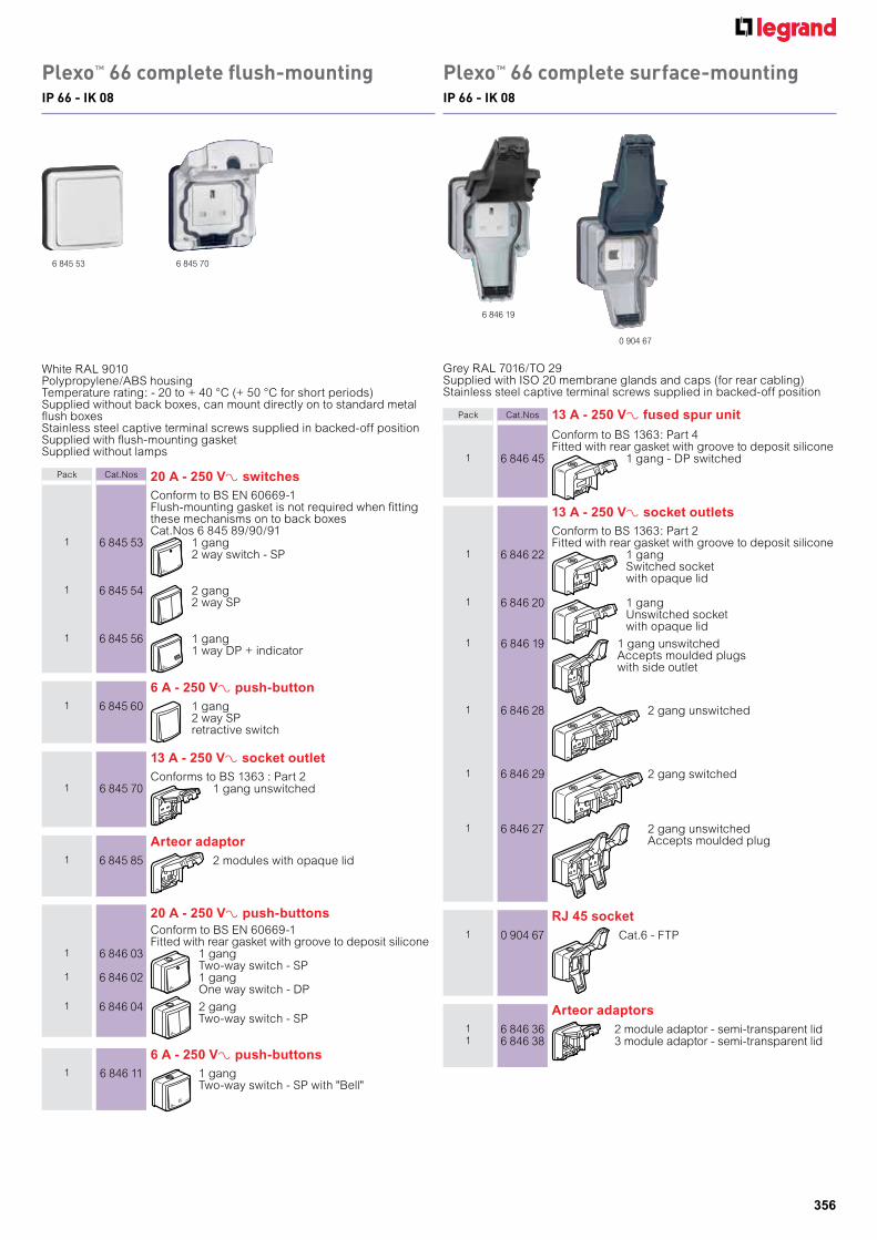
Conform to BS 1363: Part 4Fitted with rear gasket with groove to deposit silicone
1 6 846 45 1 gang - DP switched
13 A - 250 VA socket outletsConform to BS 1363: Part 2Fitted with rear gasket with groove to deposit silicone
1 6 846 22 1 gangSwitched socketwith opaque lid
1 6 846 20 1 gangUnswitched socketwith opaque lid
1 6 846 19 1 gang unswitchedAccepts moulded plugswith side outlet
1 6 846 28 2 gang unswitched
1 6 846 29 2 gang switched
1 6 846 27 2 gang unswitchedAccepts moulded plug
RJ 45 socket1 0 904 67 Cat.6 - FTP
Arteor adaptors1 6 846 36 2 module adaptor - semi-transparent lid1 6 846 38 3 module adaptor - semi-transparent lid
6 A - 250 VA push-buttons1 6 846 11 1 gang
Two-way switch - SP with "Bell"
20 A - 250 VA push-buttonsConform to BS EN 60669-1Fitted with rear gasket with groove to deposit silicone
1 6 846 03 1 gangTwo-way switch - SP
1 6 846 02 1 gangOne way switch - DP
1 6 846 04 2 gangTwo-way switch - SP
Plexo™ 66 complete surface-mountingIP 66 - IK 08
Plexo™ 66 complete flush-mountingIP 66 - IK 08
White RAL 9010Polypropylene/ABS housingTemperature rating: - 20 to + 40 °C (+ 50 °C for short periods)Supplied without back boxes, can mount directly on to standard metalflush boxesStainless steel captive terminal screws supplied in backed-off positionSupplied with flush-mounting gasketSupplied without lamps
6 845 53
6 846 19
Grey RAL 7016/TO 29Supplied with ISO 20 membrane glands and caps (for rear cabling)Stainless steel captive terminal screws supplied in backed-off position
Pack Cat.Nos 20 A - 250 VA switchesConform to BS EN 60669-1Flush-mounting gasket is not required when fittingthese mechanisms on to back boxesCat.Nos 6 845 89/90/91
1 6 845 53 1 gang2 way switch - SP
1 6 845 54 2 gang2 way SP
1 6 845 56 1 gang1 way DP + indicator
6 A - 250 VA push-button1 6 845 60 1 gang
2 way SPretractive switch
13 A - 250 VA socket outletConforms to BS 1363 : Part 2
1 6 845 70 1 gang unswitched
Arteor adaptor1 6 845 85 2 modules with opaque lid
0 904 67
6 845 70
Pack Cat.Nos 13 A - 250 VA fused spur unit
357
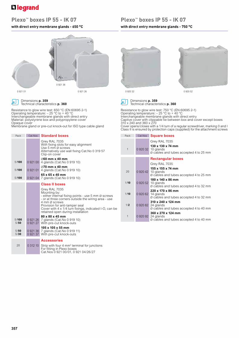
Plexo™ boxes IP 55 - IK 07with direct entry membrane glands - 750 °C
Plexo™ boxes IP 55 - IK 07with direct entry membrane glands - 650 °C
Resistance to glow wire test: 650 °C (EN 60695 2-1)Operating temperature: – 25 °C to + 40 °CInterchangeable membrane glands with direct entryMaterial: polystyrene box and polypropylene coverOpaque coverMembrane gland or pre-cut knock-out for ISO type cable gland
Resistance to glow wire test: 750 °C (EN 60695 2-1)Operating temperature: – 25 °C to + 40 °CInterchangeable membrane glands with direct entryCaptive cover with clippable tie between box and cover except boxes310 x 240 and 360 x 270Cover opens/closes with a 1/4 turn of a regular screwdriver, marking 0 and IClass II is ensured by protection caps (supplied) for the attachment screws
Pack Cat.Nos Standard boxes
Grey RAL 7035With fixing slots for easy alignmentUse 5 mm Ø screwsAlternatively use wall fixing Cat.No 0 319 57Clip-on cover
Ø60 mm x 40 mm5/100 0 921 00 4 glands (Cat.No 0 919 10)
Ø70 mm x 40 mm5/100 0 921 01 4 glands (Cat.No 0 919 10)
65 x 65 x 40 mm5/100 0 921 04 7 glands (Cat.No 0 919 10)
Class II boxesGrey RAL 7035Mounting by:- either internal fixing points - use 5 mm Ø screws- or at three corners outside the wiring area - use4 mm Ø screwsProvision for anti-tamper sealCover with 4 x 1/4 turn fixings, indicated I-O, can beretained open during installation
80 x 80 x 45 mm5/100 0 921 26 7 glands (Cat.No 0 919 10)5/50 0 921 27 With pre-cut knock-outs
105 x 105 x 55 mm5/50 0 921 36 7 glands (Cat.No 0 919 11)5/30 0 921 37 With pre-cut knock-outs
Accessories20 0 312 10 Strip with four 4 mm2 terminal for junctions
For fitting in Plexo boxesCat.Nos 0 921 00/01, 0 921 04/26/27
Pack Cat.Nos Square boxes
Grey RAL 7035
130 x 130 x 74 mm1 0 920 32 10 glands
Ø cables and tubes accepted 4 to 25 mm
Rectangular boxesGrey RAL 7035
155 x 155 x 74 mm20 0 920 42 10 glands
Ø cables and tubes accepted 4 to 25 mm
180 x 140 x 86 mm1/10 0 920 52 10 glands
Ø cables and tubes accepted 4 to 32 mm
220 x 170 x 86 mm1/10 0 920 62 14 glands
Ø cables and tubes accepted 4 to 32 mm
310 x 240 x 124 mm1/2 0 920 82 24 glands
Ø cables and tubes accepted 4 to 40 mm
360 x 270 x 124 mm1 0 920 92 24 glands
Ø cables and tubes accepted 4 to 40 mm
0 921 01 0 920 520 920 32
0 921 36
0 921 26
Dimensions p. 359Technical characteristics p. 360
Dimensions p. 359Technical characteristics p. 360

358
Plexo™ boxesaccessories
Plexo™ boxes IP 55 - IK 07with pre-cut knock-out ISO type cable entries
Resistance to glow wire test: 750 °C (EN 60695 2-1)Operating temperature: – 25 °C to + 40 °CKnock-out entriesCaptive cover with clippable tie between box and cover exceptboxes 310 x 240 and 360 x 270Cover opens/closes with a 1/4 turn of a regular screwdriver, marking 0 and IFixing with level adjustment• At 2 or 4 internal points (screw Ø5 mm max.)• At the four corners out of wiring volume (screw Ø4 mm max.)• With brackets Cat.No 0 358 02Class II is ensured by protection caps (supplied) for the attachment screws
Pack Cat.Nos Square boxes
Grey RAL 7035
130 x 130 x 74 mm1/10 0 920 34 16 knock-out entries for ISO 12/16
4 knock-out entries for ISO 20/25
Rectangular boxesGrey RAL 7035
155 x 110 x 74 mm1/10 0 920 44 16 knock-out entries for ISO 12/16
4 knock-out entries for ISO 20/25
180 x 140 x 86 mm1/5 0 920 54 16 knock-out entries for ISO 16/20
4 knock-out entries for ISO 20/25
220 x 170 x 86 mm1/5 0 920 64 12 knock-out entries for ISO 16/20
8 knock-out entries for ISO 20/254 knock-out entries for ISO 25/32
310 x 240 x 124 mm1/2 0 920 84 2 knock-out entries for ISO 16/20
22 knock-out entries for ISO 20/256 knock-out entries for ISO 25/326 knock-out entries for ISO 32/40
360 x 270 x 124 mm1 0 920 94 2 knock-out entries for ISO 16/20
18 knock-out entries for ISO 20/2510 knock-out entries for ISO 25/326 knock-out entries for ISO 32/40
0 920 34
0 920 44
0 920 84
0 919 160 919 15
0 358 02 mounted on box 0 358 00 mounted on box
Pack Cat.Nos Direct entry membrane glands
With marking of Ø for tubs and cablesDirect entry for tubes (up to 16 mm) and cables
Up to Ø2050 0 919 14 Grey (RAL 7035)
Up to Ø2550 0 919 15 Grey (RAL 7035)
Up to Ø3250 0 919 16 Grey (RAL 7035)
Up to Ø4050 0 919 17 Grey (RAL 7035)
Membrane glandsGrey (RAL 7035)With marking of Ø for tubes and cables
50 0 919 10 Up to Ø2050 0 919 11 Up to Ø25
Fixing accessoriesSet of 4 lugs
1 0 358 02 For wall fixing suppliedwith screws
Equipment accessoriesSet of 2 hinges (RAL 7016)
1 0 358 00 For boxes 130 x 130 mmup to 220 x 170 mm included
1 0 358 01 For boxes 310 x 240 and 360 x 270 mm
Dimensions p. 359Technical characteristics p. 360
359
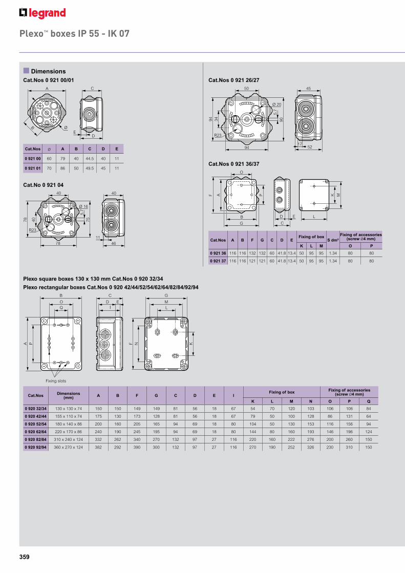
Plexo™ boxes IP 55 - IK 07
Cat.No 0 921 04
Plexo square boxes 130 x 130 mm Cat.Nos 0 920 32/34
Plexo rectangular boxes Cat.Nos 0 920 42/44/52/54/62/64/82/84/92/94
46
40 40
40
5.7
75
78
78
R23
Ø 16
11
D
C
B E
Ø
A
n Dimensions
P
A
B
Q O
I D E
C
Plots de fixation en fond de boîte
K
N
F
L M
G
Fixing slots
Cat.Nos Ø A B C D E
0 921 00 60 79 40 44.5 40 11
0 921 01 70 86 50 49.5 45 11
Cat.Nos Dimensions (mm) A B F G C D E I
Fixing of box Fixing of accessories (screw Ø4 mm)
K L M N O P Q
0 920 32/34 130 x 130 x 74 150 150 149 149 81 56 18 67 54 70 120 103 106 106 84
0 920 42/44 155 x 110 x 74 175 130 173 128 81 56 18 67 79 50 100 128 86 131 64
0 920 52/54 180 x 140 x 86 200 160 205 165 94 69 18 80 104 50 130 153 116 156 94
0 920 62/64 220 x 170 x 86 240 190 245 195 94 69 18 80 144 80 160 193 146 196 124
0 920 82/84 310 x 240 x 124 332 262 340 270 132 97 27 116 220 160 222 276 200 260 150
0 920 92/94 360 x 270 x 124 382 292 390 300 132 97 27 116 270 190 252 326 230 310 150
Cat.Nos 0 921 00/01 Cat.Nos 0 921 26/27
Cat.Nos 0 921 36/37
Cat.Nos A B F G C D EFixing of box
S dm2
Fixing of accessories (screw Ø4 mm)
K L M O P
0 921 36 116 116 132 132 60 41.8 13.4 50 95 95 1.34 80 80
0 921 37 116 116 121 121 60 41.8 13.4 50 95 95 1.34 80 80
52
45 50
34
5.7
90
94
94
R23
Ø 20
17
A
F K
O
B
G
P
M
L D E
C
360
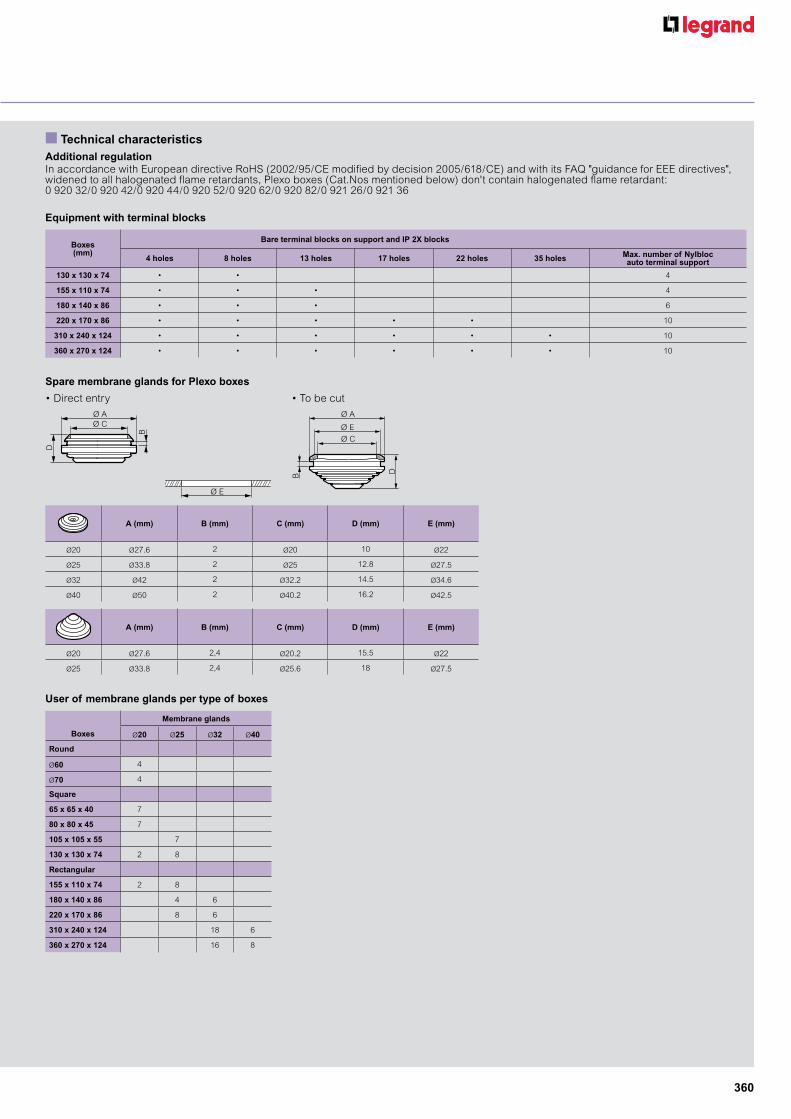
User of membrane glands per type of boxes
Equipment with terminal blocks
Spare membrane glands for Plexo boxes
n Technical characteristics
A (mm) B (mm) C (mm) D (mm) E (mm)
Ø20 Ø27.6 2 Ø20 10 Ø22
Ø25 Ø33.8 2 Ø25 12.8 Ø27.5
Ø32 Ø42 2 Ø32.2 14.5 Ø34.6
Ø40 Ø50 2 Ø40.2 16.2 Ø42.5
A (mm) B (mm) C (mm) D (mm) E (mm)
Ø20 Ø27.6 2,4 Ø20.2 15.5 Ø22
Ø25 Ø33.8 2,4 Ø25.6 18 Ø27.5
Membrane glands
Boxes Ø20 Ø25 Ø32 Ø40
Round
Ø60 4
Ø70 4
Square
65 x 65 x 40 7
80 x 80 x 45 7
105 x 105 x 55 7
130 x 130 x 74 2 8
Rectangular
155 x 110 x 74 2 8
180 x 140 x 86 4 6
220 x 170 x 86 8 6
310 x 240 x 124 18 6
360 x 270 x 124 16 8
Boxes (mm)
Bare terminal blocks on support and IP 2X blocks
4 holes 8 holes 13 holes 17 holes 22 holes 35 holes Max. number of Nylblocauto terminal support
130 x 130 x 74 • • 4
155 x 110 x 74 • • • 4
180 x 140 x 86 • • • 6
220 x 170 x 86 • • • • • 10
310 x 240 x 124 • • • • • • 10
360 x 270 x 124 • • • • • • 10
Additional regulationIn accordance with European directive RoHS (2002/95/CE modified by decision 2005/618/CE) and with its FAQ "guidance for EEE directives",widened to all halogenated flame retardants, Plexo boxes (Cat.Nos mentioned below) don't contain halogenated flame retardant:0 920 32/0 920 42/0 920 44/0 920 52/0 920 62/0 920 82/0 921 26/0 921 36
• Direct entry • To be cut
Ø E
Ø A
Ø C
B D
Ø
Trou dans la paroi
Ø C
Ø E
Ø A
D
B Ø C
Ø E
Ø A
D
B

361
for example :xxxxxxxx
Type 2 Pole 3 Pole 3 Pole + Switched Neutral
Rated Voltage / Frequency 250VAC 50/60Hz 440VAC 50/60Hz 440VAC 50/60Hz
Utilization category AC22 A / AC23 A AC22 A / AC23 A AC22 A / AC23 A
Model No / Cat No 7 353 00/P
7 353 01/P
7 353 02/P
7 353 03/P
7 353 10/P
7 353 11/P
7 353 12/P
7 353 13/P
7 353 20/P
7 353 21/P
7 353 22/P
7 353 23/P
Rated Operational current 20A 32A 40A 63A 20A 32A 40A 63A 20A 32A 40A 63A
Rated insulation voltage (a.c.) 250V 250V 250V 250V 440V 440V 440V 440V 440V 440V 440V 440V
Rated impulse withstand voltage 2500V 2500V 2500V 2500V 2500V 2500V 2500V 2500V 2500V 2500V 2500V 2500V
Rated short-time withstand cur-rent for 1 sec 240A 384A 480A 756A 240A 384A 480A 756A 240A 384A 480A 756A
Rated short-circuit making and breaking capacities for 50ms 240A 384A 480A 756A 240A 384A 480A 756A 240A 384A 480A 756A
Live terminal screws torque value2NM 2.5NM 2.5NM 2.5NM 2NM 2.5NM 2.5NM 2.5NM 2NM 2.5NM 2.5NM 2.5NM
Neutral terminal screws torque value 2NM 2NM 2NM 2.5NM 2NM 2NM 2NM 2.5NM 2NM 2.5NM 2.5NM 2.5NM
Earth terminal screws torque value 2NM 2NM 2NM 2NM 2NM 2NM 2NM 2NM 2NM 2NM 2NM 2NM
Plastic nylon screws Max. Torque value 1.8NM 1.8NM 1.8NM 1.8NM 1.8NM 1.8NM 1.8NM 1.8NM 1.8NM 1.8NM 1.8NM 1.8NM
ConductorRigid-Stranded
Min. size(sq.mm) 2.5 6 6 10 2.5 6 6 10 2.5 6 6 10
& number 1 1 1 1 1 1 1 1 1 1 1 1
Max.size(sq.mm) 4 10 10 16 4 10 10 16 4 10 10 16
Rated duty Uninterrupted duty
Note: Use padlock with shackle size Ø6.00mm when required to lock the unit in either ‘OFF’ or ‘ON’ position.
The Legrand weather proof series isolators are designed to be used with confidence for any external application. The range which includes double and triple poles offer complete protection against dust and harsh weather conditions. Coupled with a safety design, the range of isolators can be locked in either off or on position when required.
Isolatorsisolator switch

362
Dimensions (mm)
for example :xxxxxxxx
Isolatorsisolator switch
AC23A
Pack Cat.Nos Isolator switch AC22A
2 Pole 250VAC 50/60HZ1 7 353 00 2P 20A1 7 353 01 2P 32A1 7 353 02 2P 40A1 7 353 04 2P 63A
3 Pole 440VAC 50/60HZ1 7 353 10 3P 20A1 7 353 11 3P 32A1 7 353 12 3P 40A1 7 353 13 3P 63A
3 Pole + Switch neutral 440VAC 50/60HZ1 7 353 20 4P 20A1 7 353 21 4P 32A1 7 353 22 4P 40A1 7 353 23 4P 63A
Pack Cat.Nos Isolator switch AC23A
2 Pole 250VAC 50/60HZ1 7 353 00P 2P 20A1 7 353 01P 2P 32A1 7 353 02P 2P 40A1 7 353 04P 2P 63A
3 Pole 440VAC 50/60HZ1 7 353 10P 3P 20A1 7 353 11P 3P 32A1 7 353 12P 3P 40A1 7 353 13P 3P 63A
3 Pole + Switch neutral 440VAC 50/60HZ1 7 353 20P 4P 20A1 7 353 21P 4P 32A1 7 353 22P 4P 40A1 7 353 23P 4P 63A
AC22A

363
Plastic industrial boxes
Pack Cat.Nos Accessories for IP 55 - IK 07 grey RAL 7035HingesRAL 7016 - set of 2
1 0 358 00 For boxes 130 x 130 up to 270 x 170 mm included
1 0 358 01 For boxes 310 x 240 mm and 360 x 270 mm
Metal mounting platesGalvanized steel 15/10 thick
5 0 358 10 For boxes 130 x 130 mm5 0 358 11 For boxes 155 x 110 mm5 0 358 12 For boxes 180 x 140 mm5 0 358 13 For boxes 220 x 170 mm5 0 358 14 For boxes 270 x 170 mm
5/10 0 358 15 For boxes 310 x 240 mm
Wall mounting lugs1 0 358 02 Set of 4 lugs for boxes from width 110 mm
For wall fixing supplied with screws
Pack Cat.Nos IP 55 - IK 07 grey RAL 7035
Class II provided by protective caps for the fixing screws (supplied) Equipment can be fixed on rail or solid plate IP 2X terminal blocks fixed at the top from 130 x 130 mm size (p. 180) Cover opened/closed with 1/4 turn of a flat screwdriver. Indication of closed/open position: I/O Captive covers with ties, except boxes 310 x 240 mm and 360 x 270 mm
Opaque cover
Transparent cover
Internal dimensions Height x Width x Depth (mm)
5/50 0 921 28 80 x 80 x 455/50 0 921 38 105 x 105 x 55
1 0 359 00 130 x 75 x 741 0 359 30 130 x 130 x 741 0 359 40 155 x 110 x 741 0 359 50 180 x 140 x 861 0 359 60 0 359 61 220 x 170 x 861 0 359 70 0 359 71 270 x 170 x 861 0 359 80 310 x 240 x 124
IP 55 - grey RAL 7035 - increased depth
Opaquecover
Box depth 140 mmIK 07
2 0 921 22 220 x 170 x 240 mm with 4 locks
Box depth 154 mmIK 08
1 0 350 58 359 x 265 x 154 mm with hinges and 2 locks
Box depth 160 mmIK 08
1 0 922 84 310 x 240 x 160 mm with 4 locks
Smooth surfaces Choice of fixing: - Internal: 4 oblong holes at back of box - At the 4 corners outside the wiring space, with Ø4 screws - Using wall mounting lugs Cat.No 0 358 02 (except boxes 130 x 75 x 74 mm)
Can be equipped with a rail for fixing equipment
Hinges Cat.No 0 358 01
IP 2X terminal blocks fixedat the top from 130 x 130 mm
Wall mounting lugsCat.No 0 358 02 for horizontal or vertical installation
0 359 71
Weatherproof cabinets, p. 147-160

364
Plastic industrial boxes
273
182
165
9262
148.5
3.8
246
155
Ø 4.5
321
190
8278
146
9.2
12.3251
342
27128
2
211
Ø 4.5
Usable area 5.5 dm2 Weight: 2.3 kg
Usable area 3.5 dm2 Weight: 1.08 kg
200
146
60.7 79.6
132.6
233
140
183
212
144
162
80
Mounting plate
Usable area 3.7 dm2
n Characteristics - IP 55 - IK 07 boxes n Characteristics - IP 55 - increased depth boxes
n Dimensions
n DimensionsBoxes
Boxes
Metal mounting plates
Maximum length of terminals
1: Fixing for accessories (rail, mounting plates)
Box: - IP 55: polypropylene Cover: - opaque: polypropylene (except 0 359 80: polycarbonate) - transparent: polycarbonate Operating temperature: - 25 °C to + 40 °C Self-extinguishing: 750 °C (EN 60695-2-11) For indoor use
Operating temperature: - 20 °C to + 50 °C Self-extinguishing: 750 °C (EN 60695-2-11) For indoor use
Cat.NosDimensions (mm) Box fixing
(mm)Accessories fixing
(Ø4 mm screw supplied)
A B C D E F G H I J K L M N R
0 359 00 140 85 81 56 18 67 70 - 65 120 - - 51 106 -
0 359 30 150 150 81 56 18 67 54 70 120 103 102 87 106 106 84
0 359 40 175 130 81 56 18 67 79 50 100 128 112 88 86 131 64
0 359 50 200 160 94 69 18 80 104 50 130 153 137 112 116 156 94
0 359 60/61 240 190 94 69 18 80 144 80 160 193 175 142 146 196 124
0 359 70/71 290 190 94 69 18 80 194 80 160 243 226 142 146 246 122
0 359 80 332 262 132 97 27 116 220 160 222 276 248 198 200 260 150
Cat.No 0 921 28
Cat.No 0 921 38
Cat.No 0 921 22
Cat.No 0 350 58
Cat.No 0 922 84
Cat.Nos A B C D
0 358 10 114 114 106 106
0 358 11 94 139 86 131
0 358 12 124 164 116 156
0 358 13 154 204 146 196
0 358 14 154 254 146 246
0 358 15 211 271 200 260
Box dimensions (mm) Number of holes
130 x 130 x 74 8
155 x 110 x 74 13
180 x 140 x 86 13
220 x 170 x 86 22
310 x 240 x 124 28
D
A N K J G
M
L
RE
F
C I
H
(1)
(1) (1)
(1) Plots de fixation en fond de boîtier
B
52
4550
34
5.7
9094
94
R23
Ø20
11
60
41.854
95 80 37
47116
1219580
50 116
121
A
C
DB

365
for example :xxxxxxxx
Batibox™
flush-mounting boxes for dry partitions
0 800 51 0 800 42
Pack Cat.Nos 1-gang boxes
For 1 module20 0 800 40 Drilling diameter 32 mm
Depth 40 mm
For 1 gang or 2 modulesFor wiring accessories using screws or claws Drilling diameter 67 mm
50 0 800 41 Depth 40 mm50 0 800 51 Depth 50 mm
Multi-gang boxesFor mounting equipment using screws Drilling diameter 67 mm Supplied with 1 removable divider for accommodating extended functions
For 83.5 mm fixing centresDepth 40 Depth 50 Compatible with Arteor
15 0 800 49 3 modules horizontal mounting
For 60 and 71 mm fixing centresCompatible with Arteor
30 0 800 42 0 800 52 2-gang or 4/5 modules Horizontal or vertical use
30 0 800 43 0 800 53 3-gang or 6/8 modules Horizontal or vertical use
30 15 0 800 44 0 800 54 4-gang or 8/10 modules Horizontal or vertical use
Installation see e-catalogue
Pack Cat.Nos Universal covers
For converting wiring devices boxes into junction boxes or for closing up an existing box Supplied without fixing screws For one-gang or multi-gang boxes
20 0 801 80 Round cover, Ø85 mm, for 1-gang box
20 0 892 81 Square cover, 80 x 80 mm, for 1-gang box
10 0 801 82 Cover for Batibox 2-gang box
Accessory20 0 801 97 Long screw Ø3 mm
length 40 mm
366
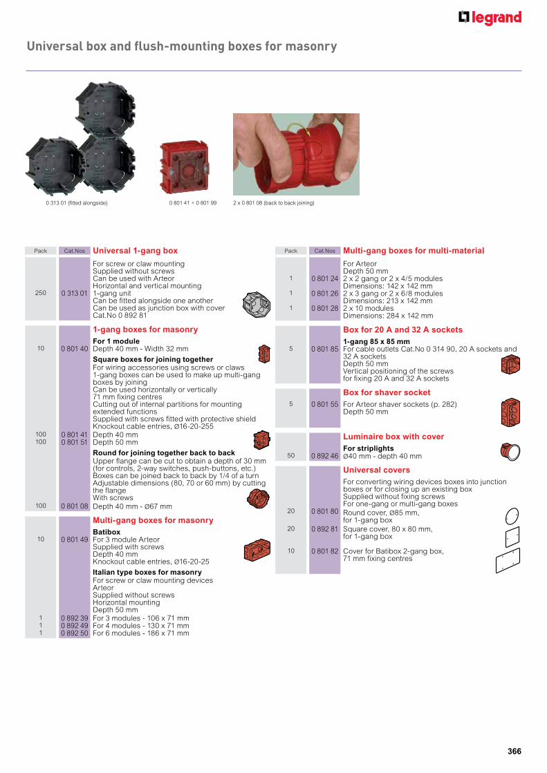
Universal box and flush-mounting boxes for masonry
0 801 41 + 0 801 99 2 x 0 801 08 (back to back joining)0 313 01 (fitted alongside)
Pack Cat.Nos Universal 1-gang box
For screw or claw mountingSupplied without screwsCan be used with ArteorHorizontal and vertical mounting
250 0 313 01 1-gang unitCan be fitted alongside one anotherCan be used as junction box with coverCat.No 0 892 81
1-gang boxes for masonryFor 1 module
10 0 801 40 Depth 40 mm - Width 32 mm
Square boxes for joining togetherFor wiring accessories using screws or claws1-gang boxes can be used to make up multi-gangboxes by joiningCan be used horizontally or vertically71 mm fixing centresCutting out of internal partitions for mountingextended functionsSupplied with screws fitted with protective shieldKnockout cable entries, Ø16-20-255
100 0 801 41 Depth 40 mm100 0 801 51 Depth 50 mm
Round for joining together back to backUpper flange can be cut to obtain a depth of 30 mm (for controls, 2-way switches, push-buttons, etc.) Boxes can be joined back to back by 1/4 of a turn Adjustable dimensions (80, 70 or 60 mm) by cutting the flange With screws
100 0 801 08 Depth 40 mm - Ø67 mm
Multi-gang boxes for masonryBatibox
10 0 801 49 For 3 module Arteor Supplied with screws Depth 40 mm Knockout cable entries, Ø16-20-25
Italian type boxes for masonryFor screw or claw mounting devices Arteor Supplied without screws Horizontal mounting Depth 50 mm
1 0 892 39 For 3 modules - 106 x 71 mm1 0 892 49 For 4 modules - 130 x 71 mm1 0 892 50 For 6 modules - 186 x 71 mm
Pack Cat.Nos Multi-gang boxes for multi-material
For Arteor Depth 50 mm
1 0 801 24 2 x 2 gang or 2 x 4/5 modules Dimensions: 142 x 142 mm
1 0 801 26 2 x 3 gang or 2 x 6/8 modules Dimensions: 213 x 142 mm
1 0 801 28 2 x 10 modules Dimensions: 284 x 142 mm
Box for 20 A and 32 A sockets1-gang 85 x 85 mm
5 0 801 85 For cable outlets Cat.No 0 314 90, 20 A sockets and 32 A sockets Depth 50 mm Vertical positioning of the screws for fixing 20 A and 32 A sockets
Box for shaver socket5 0 801 55 For Arteor shaver sockets (p. 282)
Depth 50 mm
Luminaire box with coverFor striplights
50 0 892 46 Ø40 mm - depth 40 mm
Universal coversFor converting wiring devices boxes into junction boxes or for closing up an existing box Supplied without fixing screws For one-gang or multi-gang boxes
20 0 801 80 Round cover, Ø85 mm, for 1-gang box
20 0 892 81 Square cover, 80 x 80 mm, for 1-gang box
10 0 801 82 Cover for Batibox 2-gang box, 71 mm fixing centres

367
for example :xxxxxxxx
for example :xxxxxxxx
Nylbloc™
connection strips and connectors without screws
Nylbloc™ autoscrewless connection terminals
0 343 22 0 343 23 0 343 25 0 343 28
0 342 17 0 342 21
Pack Cat.Nos Screwless connection terminals - Nylbloc autoNo tool direct connection after simple stripping of copper conductors Test socket for tester screwdriver or test tip Cat.No 0 394 45 (p. 286) for IP 2X test or Ø4 mm tip on Nylbloc auto terminals Conform to EN 60998-2-2 For rigid cable from 0.75 to 2.5 mm2 Stripping length: 11 mm Connection by separate crimping blades Transparent base providing full visibility of the connections Colour code to identify products Duplix marking possible on 3, 5 and 8-wire terminals Max. intensity: 24 A Insulating voltage: 450 V±
100 0 343 22 Grey terminal for 2 wires100 0 343 23 Orange terminal for 3 wires100 0 343 25 Blue terminal for 5 wires50 0 343 28 Grey terminal for 8 wires
AccessoriesConductor stripping tool
5 0 343 99 For cable desheathing and rapid wire stripping in flush-mounting and junction boxes, in trunking For cable Ø8 mm to 13 mm (from 2 G 1.5 to 5 G 2.5 mm2) and wires 1.5 mm2 and 2.5 mm2
Nylbloc auto terminal support10 0 343 98 For up to 3 screwless connection terminals Nylbloc
auto (Cat.Nos 0 343 22/23/25/28) Direct fixing: - in top of Plexo boxes and industrial plastic cabinets ≥ 130 x 130 mm - on flat bar 12 x 2 mm - in bottom of fully assembled, adaptable and aluminium DLP trunkings (from 50 x 80 mm) Screw fixing: - in bottom of Plexo boxes ≥ 105 x 105 mm and industrial plastic cabinets - universal Fixing on rail with accessory Cat.No 0 048 11 (p. 129) Accessible test socket Marking zone with felt tip pen Cat.No 0 395 98 (p. 197)
Pack Cat.Nos Nylbloc connection strips
12 elements with captive screws Supplied with screws undone Flame retardant polypropylene (– 25 °C to + 100 °C) Ambient temperature from – 25 °C to + 55 °C (T 55) Conform to EN 60998-2-1 and EN 60664-1 Self-extinguishing to EN 60695-2-11 at 850° Insulation voltage: 250 V according to EN 60 998-2-1 Use at 400 V integrated in a series of products that comply with the requirements of EN 60664-1, pollution degree 2, overload category III
Black
Ratedcapacity
(mm2)Hole Ø(mm)
Max current(A)
10 0 342 11 2.5 2.5 2410 0 342 13 6 3.5 4110 0 342 15 10 4.5 5710 0 342 17 16 5.5 7610 0 342 19 25 7 101
White10 0 342 21 2.5 2.5 2410 0 342 23 6 3.5 4110 0 342 25 10 4.5 5710 0 342 27 16 5.5 76
Connectors without screws - Capvis capsRapid connection for 1.5 - 2.5 - 4 and 6 mm2 solid conductor cables - 440 V insulation
Nominalcapacity
(mm2)
No of cablesand corresponding
sections (mm2)
Capcolour
Packagingtype
1000 0 343 38 1.5 3 to 5 of 0.52
2 to 4 of 0.752
2 of 1.52
blue box
1000 0 343 44 1.5 to 2.5 3 to 5 of 0.52
2 to 5 of 0.752
2 to 3 of 1.52
2 of 2.52
orange box
2000 0 343 51 4 2 to 4 of 1.52
2 to 3 of 2.52
2 of 42
yellow box
100 0 343 57 6 2 to 5 of 2.52
2 to 3 of 42
2 of 62
red box
2 000 6 340 51 4 2 to 4 of 1.52
2 to 3 of 2.52
2 of 42
yellow bucket
1 500 6 340 52 6 2 to 5 of 2.52
2 to 3 of 42
2 of 62
red bucket
0 343 44 6 340 51 6 340 516 340 520 343 38

368
for example :xxxxxxxx
for example :xxxxxxxx
British standard plugs,travel adaptors and TV plugs
0 503 26
Pack Cat.Nos British standard plugs
20 0 503 26 13 A - 250 V± - 2P+TASTA certification
20 6 500 13 13 A - 250 V± - 2P+T
20 6 500 15 15 A - 250 V± - 2P+T
Travel adaptorsWith safety shuttersFor connecting a plug onto a different standardsocket
White/Grey
CardboardBritish standard adaptor → French standard adaptor
10 0 503 83 2P+E - 16 A outlet - 13 A input - 3.000 W at 230 V±British standard plug on a French or Germanstandard socket
German standard adaptor → French standard adaptor
10 0 503 82 2P+E - 16 A outlet - 3.680 W in 230 V±German standard plug (countries: Germany,Spain, Austria, Portugal, Greece, Hungary…)on a French socket
2P adaptors - Euro/US10 0 503 85 US standard → European standard
US standard plug on a French or German standardsocket - 1.380 W max.
10 0 503 86 European standard → US standardFrench or German standard plug on a US standardsocket - 1.875 W max.
TV plugsØ9.52 mm
50 0 500 09 Male plug50 0 500 10 Female plug
6 500 13 6 500 15
0 503 820 503 83
ASTA(UK)
0 500 10
LegrandPackaging
Practical and, eco-friendly
Legrand packaging – your assistance of acertified original product which is factoryinspected, protected and clearly identifiable
®
dustproof flaps:effective protection of the product resealable box:
for easy management of the contents
eco-friendly:- recyclable cardboard
packaging- Printing inks comply with
environmental standards
informative label:- catalogue number/
quantity- Picture of the product- clear description- Technical information- Barcode- regulatory marking
The red and white box and the logo are registered trademarks

369
for example :xxxxxxxx
for example :xxxxxxxx
Bells, bell pushes, shaverlightChimes
6 915 06
Incandescent shaverlight - British standardConform to BS EN 60598 and IEE wiring regulations(16th edition)For linear incandescent tube, Ø25 mm, length 284 mmPolycarbonate diffuserPull cord switch in front + 2P socketprotected by a 20 VA transformerSupplied without lamp
1 6 915 06 Incandescent shaverlight IP 24 - IK 04
Pack Cat.Nos Surface-mounting radio-controlled chimes
230 V chime kit1 0 416 13 Composition:
- weatherproof push-button- receiverChoice of 15 melodies433 MHz - Range 100 mConfiguration via switch to avoid interference
8 V chime kit with light indicator1 0 416 10 Composition:
- weatherproof push-button- receiverChoice of 36 melodies3 adjustable sound levels - Range 100 m2 x 1.5 V AA alkaline batteries (not included)Preset configurationWall and table mountingPossibility to connect 4 push-buttons
8 V chime kit1 0 416 11 Composition:
- weatherproof push-button- receiverChoice of 36 melodies2 x 1.5 V AA alkaline batteries (not included)Preset configurationRange 100 mWall mounting
Radio controlled push-button1 0 416 17 Additional push-button for Cat.No 0 416 10
Electromechanical chimesWhiteDim.: 116 x 116 x 48 mmTone level: 80 dB at 1 m
8-12 VA chime1 0 416 50 Compatible with non-illuminated push-button
Cat.No 0 416 46 or illuminated push-buttonsCat.Nos 0 416 45/47Use a 8 VA transformer Cat.No 0 042 25 or 0 420 25
230 VA chime1 0 416 51 2 note chime - 50/60 Hz
Compatible with illuminated push-buttonCat.No 0 416 45
230 VA chime with transformer1 0 416 52 50/60 Hz with built-in 8-12 V transformer
Class IICompatible with non-illuminated push-buttonCat.No 0 416 46 or illuminated push-buttonsCat.Nos 0 416 45/47
Pack Cat.Nos Bell pushes
Surface-mountingWhiteSupplied without fixing screws
24 V - 2 A bell push5 0 416 46 IP 30 - class III W
Dim.: 50 x 25 x 20 mm
230 V - 2 A bell push with illuminated label holder
10 0 416 45 IP 30 - class IISupplied without lampDim.: 70 x 35 x 24 mmUse lamps Cat.No 0 898 26 - 12 Vand Cat.No 0 898 21 - 220 V
24 V - 2 A universal - bell push with label holder10 0 416 47 Weatherproof IP 44 (IK 07) - Class III W
Dim.: 70 x 70 x 25 mmIlluminated with lamp Cat.No 0 898 26Can be used with any type of chimes (electronic orelectromechanical)
Lido bellsIP 20 - IK 04Average acoustic output at 1 m: 80 dB at 1 mSurface-mounting with screws with levelling facilities
Class II(double insulated) Consumption
(mA)Averageacousticoutput at1 m in dB
10 0 412 21 230 V± - 50/60 Hz Dim.: 95 x 61 x 33 mm
30 80
With built-in transformer1 0 412 43 230 V± - 50/60 Hz 45 80
Dim.: 135 x 88 x 48 mmWarning: take lamps out of the bell pushes
0 416 46 0 412 430 416 500 416 10 0 416 11

370
for example :xxxxxxxx
for example :xxxxxxxx
Colour video door entry kitwiring diagrams
Colour video door entry kit1 apartment - 4-wires
+
Surface-mounting street panel4 wires (+ 2 to open the gate)The monitor allows surveillance and opening of the gateThe system allows 2 additional monitors, with intercom function
Pack Cat.Nos 7'' colour video kits - hands free
British standard1 3 690 83 Complete video kit
Composition:- 1 metal street panel (entrance) with LEDs- 1 colour 7’’ monitor with integrated power supplyand British standard plug and cable- 1 wall-mounting base- 1 set of screws for wall fixing
1 3 690 88 Additional video internal unit
3 690 83 : Complete video kit
n Colour screen analog video kit - Hands free
n Colour screen analog video kit - with handset
VIDEO OUT VIDEO OUT VIDEO OUT
DC 15V DC 15V DC 15V
Optional
Optional 100-240 Vac(50/60 Hz)
100-240 Vac(50/60 Hz)
100-240 Vac(50/60 Hz)

371
Audio door entry kit with handsetwiring diagram
Audio door entry kit with handset1 apartment - 4-wires
Surface-mounting street panel2 wires (+ 2 to open the gate)Opening of gate with handsetThe system allows 2 additional audio internal unitsCan be used as intercom within the house
Pack Cat.Nos British standard
+ +
3 690 00
n Audio kit - with handset
=
Optional
1 3 690 03 Complete audio kitComposition:- 1 slim street panel (entrance)- 1 audio handset with transformer equipped withBritish standard plug- 1 set of screws for wall fixing
1 3 690 08 Additional audio internal unit with transformerequipped with British standard plug

372
INSTALLATION OF UP TO:
4000
800
80
16
100
1 km
2 km
Apartments
Handsets per riser
Entrance panels per riser
Porter switchboards
Riser shunts
Distance for colour video installation
Distance for B/W video installation
D45 system auDio anD viDeo Door entry system
Security systemfor your Home
HiGH PerFormanCe For muLti-storey anD LarGe BuiLDinGs
automatically equalizes and amplifies the video signals, providing high quality video performance even with long cable runs
no intermediate amplifier needed for video:- black and white video signals can reach up to 2 km- colour video signals can reach 1 km
tHe simPLiCity
use of utP cables and rJ45 connectors is easyand economical compared to traditional cableinstallations
a security monitoring system using serial devices connected using DiGitaL Bus technologies. the system is designed to performed such functions as call, doorbell, conversation, monitor, unlock, network and alarms, by connecting riser system network device
innovative seCurity FunCtions
sos pushbutton on all indoor handsets intercom between all riser apartments anti-tamper function on indoor handsets Possibility to connect an additional camera to switchboard