Wireless Pushbutton Switch User's Manual · nation with any electrical or electronic components,...
98
Wireless Pushbutton Switch A265-E1-02 User's Manual A2W-R-WC1 A2W-T-WC1 Trouble Shooting Appendix Overview Operating Procedure Registration in the ID Mode Installation and Wiring of the Master Unit Survey of the Operating Environment and System Design Run in the RUN Mode Wireless Test in the TEST Mode 1 2 3 5 6 7 8 A 4
Transcript of Wireless Pushbutton Switch User's Manual · nation with any electrical or electronic components,...

Wireless Pushbutton Switch
A265-E1-02
User's ManualA2W-R -WC1A2W-T -WC1
Trouble Shooting
Appendix
Overview
Operating Procedure
Registration in the ID Mode
Installation and Wiring of the Master Unit
Survey of the Operating Environment and System Design
Run in the RUN Mode
Wireless Test in the TEST Mode
1
2
3
5
6
7
8
A
4

CopyrightsMicrosoft product screen shots reprinted with permission from Microsoft Corporation.
All rights reserved. No part of this publication may be reproduced, stored in a retrieval system, or transmitted, in any form, or by any means, mechanical, electronic, photocopying, recording, or otherwise, without the prior written permission of OMRON.
No patent liability is assumed with respect to the use of the information contained herein. Moreover, because OMRON is constantly striving to improve its high-quality products, the information contained in this manual is subject to change without notice. Every precaution has been taken in the preparation of this manual. Neverthe-less, OMRON assumes no responsibility for errors or omissions. Neither is any liability assumed for damages resulting from the use of the information contained in this publication.
NOTE
Microsoft, Windows is either registered trademarks or trademarks of Microsoft Corporation in the United States and other countries.
Other company names and product names in this document are the trademarks or registered trademarks of their respective companies.
Trademarks

1
Preface
Wireless Pushbutton Switch User’s Manual (A265)
Preface
Thank you for purchasing an Wireless Pushbutton Switches System (A2W-R-WC1 Master Unit and A2W-T-WC1 Slave button).
This manual describes how to use the Master Unit and Slave button. Read this manual thoroughly and be sure you understand it before attempting to use this products and use the products correctly accord-ing to the information provided. Keep this manual in a safe place for easy reference.
PDF version of this manual can be downloaded from the OMRON website.
(http://www.ia.omron.com)
Terms and Conditions Agreement
2 Wireless Pushbutton Switch User’s Manual (A265)
Terms and Conditions Agreement
Exclusive Warranty
Omron’s exclusive warranty is that the Products will be free from defects in materials and workman-ship for a period of twelve months from the date of sale by Omron (or such other period expressed in writing by Omron). Omron disclaims all other warranties, express or implied.
Limitations
OMRON MAKES NO WARRANTY OR REPRESENTATION, EXPRESS OR IMPLIED, ABOUT NON-INFRINGEMENT, MERCHANTABILITY OR FITNESS FOR A PARTICULAR PURPOSE OF THE PRODUCTS. BUYER ACKNOWLEDGES THAT IT ALONE HAS DETERMINED THAT THE PRODUCTS WILL SUITABLY MEET THE REQUIREMENTS OF THEIR INTENDED USE.
Omron further disclaims all warranties and responsibility of any type for claims or expenses based on infringement by the Products or otherwise of any intellectual property right.
Buyer Remedy
Omron’s sole obligation hereunder shall be, at Omron’s election, to (i) replace (in the form originally shipped with Buyer responsible for labor charges for removal or replacement thereof) the non-com-plying Product, (ii) repair the non-complying Product, or (iii) repay or credit Buyer an amount equal to the purchase price of the non-complying Product; provided that in no event shall Omron be responsible for warranty, repair, indemnity or any other claims or expenses regarding the Products unless Omron’s analysis confirms that the Products were properly handled, stored, installed and maintained and not subject to contamination, abuse, misuse or inappropriate modification. Return of any Products by Buyer must be approved in writing by Omron before shipment. Omron Companies shall not be liable for the suitability or unsuitability or the results from the use of Products in combi-nation with any electrical or electronic components, circuits, system assemblies or any other materi-als or substances or environments. Any advice, recommendations or information given orally or in writing, are not to be construed as an amendment or addition to the above warranty.
See http://www.omron.com/global/ or contact your Omron representative for published information.
OMRON COMPANIES SHALL NOT BE LIABLE FOR SPECIAL, INDIRECT, INCIDENTAL, OR CON-SEQUENTIAL DAMAGES, LOSS OF PROFITS OR PRODUCTION OR COMMERCIAL LOSS IN ANY WAY CONNECTED WITH THE PRODUCTS, WHETHER SUCH CLAIM IS BASED IN CONTRACT, WARRANTY, NEGLIGENCE OR STRICT LIABILITY.
Further, in no event shall liability of Omron Companies exceed the individual price of the Product on which liability is asserted.
Warranty, Limitations of Liability
Warranties
Limitation on Liability; Etc

3
Terms and Conditions Agreement
Wireless Pushbutton Switch User’s Manual (A265)
Omron Companies shall not be responsible for conformity with any standards, codes or regulations which apply to the combination of the Product in the Buyer’s application or use of the Product. At Buyer’s request, Omron will provide applicable third party certification documents identifying ratings and limitations of use which apply to the Product. This information by itself is not sufficient for a com-plete determination of the suitability of the Product in combination with the end product, machine, sys-tem, or other application or use. Buyer shall be solely responsible for determining appropriateness of the particular Product with respect to Buyer’s application, product or system. Buyer shall take applica-tion responsibility in all cases.
NEVER USE THE PRODUCT FOR AN APPLICATION INVOLVING SERIOUS RISK TO LIFE OR PROPERTY OR IN LARGE QUANTITIES WITHOUT ENSURING THAT THE SYSTEM AS A WHOLE HAS BEEN DESIGNED TO ADDRESS THE RISKS, AND THAT THE OMRON PRODUCT(S) IS PROPERLY RATED AND INSTALLED FOR THE INTENDED USE WITHIN THE OVERALL EQUIP-MENT OR SYSTEM.
Omron Companies shall not be responsible for the user’s programming of a programmable Product, or any consequence thereof.
Data presented in Omron Company websites, catalogs and other materials is provided as a guide for the user in determining suitability and does not constitute a warranty. It may represent the result of Omron’s test conditions, and the user must correlate it to actual application requirements. Actual perfor-mance is subject to the Omron’s Warranty and Limitations of Liability.
Product specifications and accessories may be changed at any time based on improvements and other reasons. It is our practice to change part numbers when published ratings or features are changed, or when significant construction changes are made. However, some specifications of the Product may be changed without any notice. When in doubt, special part numbers may be assigned to fix or establish key specifications for your application. Please consult with your Omron’s representative at any time to confirm actual specifications of purchased Product.
Information presented by Omron Companies has been checked and is believed to be accurate; how-ever, no responsibility is assumed for clerical, typographical or proofreading errors or omissions.
Application Considerations
Suitability of Use
Programmable Products
Disclaimers
Performance Data
Change in Specifications
Errors and Omissions

Safety Precautions
4 Wireless Pushbutton Switch User’s Manual (A265)
Safety Precautions
The following notation is used in this manual to provide precautions required to ensure safe usage of a Wireless Pushbutton Switch. The safety precautions that are provided are extremely important to safety. Always read and heed the information provided in all safety precautions.
The following notation is used.
Key to Warning Symbols
Definition of Precautionary Information
WARNINGIndicates a potentially hazardous situation which, if not avoided, could result in death or serious injury. Additionally, there may be severe property damage.
CAUTION Indicates a potentially hazardous situation which, if not avoided, may result in minor or moderate injury, or property damage.
Symbols
Symbol Meaning
Caution
• General Caution
Indicates non-specific general cautions, warnings, and dangers.
• Electrical Shock Caution
Indicates possibility of electric shock under specific conditions.
Prohibition
• General Prohibition
Indicates non-specific general prohibitions.
• Disassembly Prohibition
Indicates prohibitions when there is a possibility of injury, such as from electric shock, as the result of disassembly.
Mandatory Caution
• General Caution
Indicates non-specific general cautions, warnings, and dangers.
5
Safety Precautions
Wireless Pushbutton Switch User’s Manual (A265)
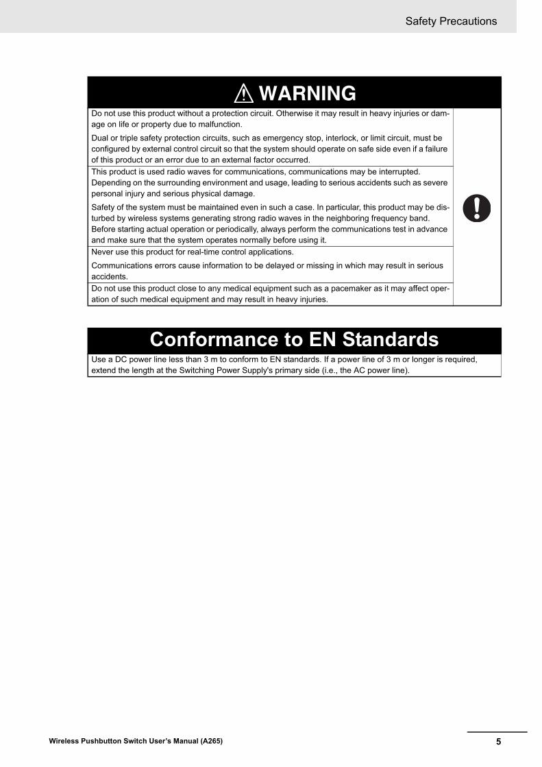
WARNINGDo not use this product without a protection circuit. Otherwise it may result in heavy injuries or dam-age on life or property due to malfunction.
Dual or triple safety protection circuits, such as emergency stop, interlock, or limit circuit, must be configured by external control circuit so that the system should operate on safe side even if a failure of this product or an error due to an external factor occurred.
This product is used radio waves for communications, communications may be interrupted. Depending on the surrounding environment and usage, leading to serious accidents such as severe personal injury and serious physical damage.
Safety of the system must be maintained even in such a case. In particular, this product may be dis-turbed by wireless systems generating strong radio waves in the neighboring frequency band. Before starting actual operation or periodically, always perform the communications test in advance and make sure that the system operates normally before using it.
Never use this product for real-time control applications.
Communications errors cause information to be delayed or missing in which may result in serious accidents.
Do not use this product close to any medical equipment such as a pacemaker as it may affect oper-ation of such medical equipment and may result in heavy injuries.
Conformance to EN StandardsUse a DC power line less than 3 m to conform to EN standards. If a power line of 3 m or longer is required, extend the length at the Switching Power Supply's primary side (i.e., the AC power line).
Precautions for Safe Use
6 Wireless Pushbutton Switch User’s Manual (A265)
Precautions for Safe Use
Observe the following precautions when using this product:
(1) Avoid this product from coming in contact with water, oil, solvents, detergents, etc. during transpor-
tation or storage, and make sure it is not subjected to excessive vibrations and impact, or dropped
down. Use a dedicated packaging box when storing this product.
(2) Storage of this product must be within the specified environment. Allow the product to warm up to
room temperature for at least 3 hours after it has been stored at -10°C or lower.
(3) Use the product within the specified temperature and humidity ranges.
(4) Do not use the product under the following locations:
• Locations subject to static electricity, excessive noise, or electric fields.
• Locations where the product may come into contact with water, oil, or chemicals.
• Locations where corrosive gases or flammable gases are present.
• Locations where large amounts of dust or dirt are present.
• Locations subject to spatters, iron chips, or fillings.
• Locations subject to direct sunlight.
(5) To ensure the antenna does not come off during operation, attach it right into the connector.
(6) Do not pull or grab the antenna while carrying or handling the product.
(7) The use of this product at other than the designated frequency is prohibited by the Radio Law. Use
this product after confirming the frequency and product type according to the country of use.
(8) Do not use the product outdoors (outside a control panel).
(9) Tighten the mounting screws to the specified torque of 4.4 to 5.3 in lb. (0.5 to 0.6 N•m)
(10) This product can be mounted at tight contact in the left and right direction, however do not mounted
at tight contact to other heat generating products so as not to obstruct heat release.
(11) Do not use other than the default mounting method.
(12) Doing so may result in the product damaged or malfunction. Do not subject any product to abnor-
mal vibration or shock and dropped it on the floor or otherwise subjected to excessive shock. To
prevent damage from falls, OMRON recommends securing this product with screws when mount-
ing it on walls, etc. Stop using this product if it is subjected to strong impacts.
(13) When mounting the designated antenna with magnet, mount it directly on a steel plate to secure
mounting strength.
(14) When mounting the designated antenna with magnet, do not install the antenna cable together
with the power line or electric cables. Also, do not forcefully pull or bend the cable, or keep any
object on top.
(15) Minor electric shock, fire, or Product failure may occasionally occur. Do not allow any pieces of
metal or conductors or any clippings or cuttings resulting from installation work to enter the Prod-
uct.
(16) Do not apply voltages and to the output Terminals in excess of the maximum switching capacity.
(17) Do not insert more than one wire into each terminal insertion hole.
(18) Do not wire anything to the release holes.
(19) Do not push the terminal block with a force exceeding 40 N when inserting wires or when inserting
a flat-blade screwdriver in a release hole.
(20) Do not bend a wire past its natural bending radius or pull on it with excessive force. Doing so may
cause the wire disconnection.
Master Unit

7
Precautions for Safe Use
Wireless Pushbutton Switch User’s Manual (A265)
(21) Do not tilt or twist a flat-blade screwdriver while it is inserted into a release hole on the terminal
block. The terminal block may be damaged.
(22) Do not allow the flat-blade screwdriver to fall out while it is inserted into a release hole.
(23) Insert a flat-blade screwdriver into the release holes at an angle. The terminal block may be dam-
aged if you insert the screwdriver straight in.
(24) Do not apply unnecessary strong force on various operation switches as that may damage the
switches.
(25) You will have to make the settings during installation or replacement. Make the settings correctly
according to the manual, perform the communications test in advance, and make sure that the sys-
tem operates normally before using it. Unintended communications may occur with the other sys-
tems during replacement. Therefore, delete the registration of all wireless push buttons once.
(26) If vibrations or impacts are suspected, use wires with ferrules, or stranded wires.
(27) Before starting operation, make sure there are no faults in the wires and switch settings.
(28) This product may either hinder or be hindered by a wireless system emitting radio waves in the
same frequency band. This product may be disturbed or interfere by a wireless system emitting
radio waves in the same frequency band. Always perform the communications test in advance,
and make sure that the system operates normally before using it.
(29) Do not use this product near a device that may function abnormally due to the radio waves emitted
by this product.
(30) If an error display or output occurs, be sure to use this product after removing the cause.
(31) Minor electric shock, fire, or product failure may occasionally occur. Do not disassemble, modify,
fix, or touch inside of this product. Disassembly and modification are prohibited by the Radio Law
in each country.
(32) To prevent wiring materials from smoking or ignition, confirm wire ratings and use the wiring mate-
rials given in the following table.
• Recommended wires
• Stripping length
Recommended wires Wiring material
(mm2) (AWG)
0.25 to 2.5 24 to 14
Recommended Wire Type Ferrules lengthRecommended stripping length
Ferrules used Ferrules not used
0.25 to 1.5 mm2/AWG24 to AWG16 8 mm 10 mm 8 mm
10 mm 12 mm 10 mm
2 to 2.5 mm2/AWG14 10 mm 12 mm 10 mm
Precautions for Safe Use
8 Wireless Pushbutton Switch User’s Manual (A265)
(1) The switching function performance may be insufficient. Do not drop the product.
(2) When storing this product, avoid hazardous gases (H2S, SO2, NH3, HNO3, Cl2, etc.), dust, high
temperature and high humidity.
(3) Storage temperature must be -10°C to +70°C with no condensation.
(4) Do not use the product under the following locations:
• Locations subject to spatters, iron chips, or fillings.
• Locations subject to solvents such as detergent and thinner.
(5) The product is protected from dust and water intrusion, but the operating part is not protected from
fine foreign matter and water, so please do not let foreign matter or water enter. It may cause early
wear, damage, etc.
(6) The product may malfunction. Do not drop the product.
(7) The durability of the product varies greatly depending on operating conditions. Be sure to check
the operation under actual conditions before using the product, and use within the number of oper-
ations that have no problem in terms of performance.
(8) Do not maintain or repair the product equipment user. Be sure to consult with the equipment or
machinery manufacturer.
(9) Normal operation may not be possible. Do not attempt to disassemble, repair, or modify any prod-
ucts.
Slave button

9
Precautions for Correct Use
Wireless Pushbutton Switch User’s Manual (A265)
Precautions for Correct Use
Always heed these precautions to prevent faulty operation, malfunction, or adverse affect on the prod-uct's performance and functionality.
(1) Communications performance may be affected by its environment. Always confirm its operation
before using it.
(2) Install this product at a location where there is an unobstructed view between the wireless push
buttons and the Master Unit. Note that if the wireless push buttons are operated simultaneously, it
may lead to improper reception. Take measures to ensure safe operation of the system in such a
case as well.
(3) When multiple Master Units are used for a single wireless push button, the reception confirmation
LED of the wireless push button lights up either in green or yellow if transmission/reception with
any one Master Unit is successful. Therefore, it may not be possible to determine even if there is a
Master Unit with which transmission/reception has failed only from the display status of the wire-
less push button. Take measures to ensure safe operation of the system in such a case as well.
(4) Do not mount the antenna at a location surrounded by metal, such as inside the panel.
(5) Mount the antenna while ensuring that it is not parallel with the wiring or metal plate. Also, ensure a
safe distance from the wiring and metal plate.
(6) Do not use this product at a location with an extremely high humidity, or near a television or radio,
or an object from which sparks may fly out such as a motor or drill, or even near fluorescent light-
ing.
(7) The Radio Law prohibits connecting an antenna other than that designated. Never change the
antenna.
(8) Do not reverse the power supply connection or connect the product to an AC power supply.
(9) Use the correct power supply voltage.
(10) Do not operate the Setting Switches of the Master Unit while the Wireless Pushbutton Switches
System is in operation.
(11) Always turn OFF the power before replacing the wiring or devices.
(12) Do not handle with wet hands.
(13) Handle this product as industrial waste during disposal.
(14) If communications troubles occur frequently, refer to the Troubleshooting section in the User Man-
ual for details on the actions to take.
(15) After pressing a Slave button, wait for 100 ms before pressing the next Slave button, because the
Master Unit can not receive at the same time signals of multiple Slave buttons.
(16) If you register a Slave button to the Master Unit in an environment where another wireless push-
button switch system is operating around it, it can be erroneously set. Therefore, when registering
a Slave button, perform in an environment where the system of another wireless pushbutton switch
is not operated.
(17) Register Slave buttons to one Master Unit one by one. Be sure to set the other Master Units to the
"RUN mode" or "TEST mode".
Master Unit

Precautions for Correct Use
10 Wireless Pushbutton Switch User’s Manual (A265)
(1) Check the indicators of the product in the following cases. The product was stored outside the
environmental conditions, condensation has occurred in the product, the product has been
dropped, or the product stored for more than one year for a long time.
(2) Do not operate excessive force to the product.
(3) This product is specifically designed for indoor use only. If you use the product outdoors, it may
cause malfunction.
(4) Do not use the product in liquid such as water or oil, or do not use in locations subject to exposure
to water or oil. Doing so may result in water or oil entering inside the product.
(5) Do not use the product under the following locations:
• Places subject to intense temperature change.
• Places subject to condensation as the result of severe changes in temperature.
(6) Do not use the product in hazardous gases (H2S, SO2, NH3, HNO3, Cl2, etc.) or in high temperature
and high humidity atmosphere. It may cause damage due to corrosion.
(7) Do not use the Product in locations subject to vibrations.
(8) Do not use in locations with high frequency noise. It may cause malfunction.
(9) When installing the product, check the interference effect at the same frequency of the product.
(10) The indicator light in the display window of the product as follows; Lit green during normal opera-
tion, lit yellow when the radio field strength is weak, lit red when communications were failed.
When using the product, check the result of wireless communications with the display window.
(11) Do not apply excessive force to the product.
(12) Perform periodic inspections.
Slave button

11
Revision History
Wireless Pushbutton Switch User’s Manual (A265)
Revision History
A manual revision code appears as a suffix to the catalog number on the front and back covers of the manual.
Revision code Date Revised content
01 December 2017 Original production
02 April 2018 Made revisions related to the addition of Wireless Switch Support Tool.
A265-E1-02Revision code

Revision History
12 Wireless Pushbutton Switch User’s Manual (A265)
1
2
4
5
6
7
8
A
4
5
6
7
8
3
2
1
A
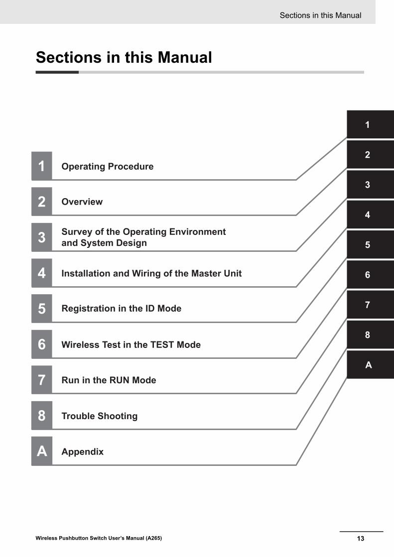
Operating Procedure
Overview
Installation and Wiring of the Master Unit
Registration in the ID Mode
Wireless Test in the TEST Mode
Trouble Shooting
Appendix
3 Survey of the Operating Environment and System Design
Run in the RUN Mode
13
Sections in this Manual
Wireless Pushbutton Switch User’s Manual (A265)
Sections in this Manual

CONTENTS
14 Wireless Pushbutton Switch User’s Manual (A265)
CONTENTS
Preface ......................................................................................................................1
Terms and Conditions Agreement ..........................................................................2Warranty, Limitations of Liability .................................................................................................................. 2Application Considerations .......................................................................................................................... 3Disclaimers .................................................................................................................................................. 3
Safety Precautions ...................................................................................................4Definition of Precautionary Information........................................................................................................ 4Symbols ....................................................................................................................................................... 4
Precautions for Safe Use.........................................................................................6
Precautions for Correct Use....................................................................................9
Revision History ..................................................................................................... 11
Sections in this Manual .........................................................................................13
CONTENTS..............................................................................................................14
Section 1 Operating Procedure
1-1 Overall Operating Procedure................................................................................................ 1-21-1-1 Overall Flowchart ........................................................................................................................ 1-2
Section 2 Overview
2-1 Overview and Features ......................................................................................................... 2-22-1-1 Overview ..................................................................................................................................... 2-22-1-2 Features...................................................................................................................................... 2-32-1-3 Major Application Examples........................................................................................................ 2-3
2-2 System Configurations ......................................................................................................... 2-42-2-1 Using the Pencil Antenna Standard Included.............................................................................. 2-42-2-2 Using Optional High-sensitivity Magnetic-base Antenna ............................................................ 2-52-2-3 Relationship Between Slave Buttons and Master Unit................................................................ 2-6
2-3 List of Models ........................................................................................................................ 2-82-3-1 Master Unit and Option ............................................................................................................... 2-82-3-2 Slave Button and Options ........................................................................................................... 2-9
2-4 Nomenclature and Functions ............................................................................................. 2-102-4-1 Master Unit................................................................................................................................ 2-102-4-2 Slave Button.............................................................................................................................. 2-14
2-5 Specifications and Functions............................................................................................. 2-152-5-1 Wireless Specifications ............................................................................................................. 2-152-5-2 Ratings...................................................................................................................................... 2-162-5-3 Operation Mode ........................................................................................................................ 2-182-5-4 Assignment Relationship Between Slave Button and Outputs of Master Unit .......................... 2-18

15
CONTENTS
Wireless Pushbutton Switch User’s Manual (A265)
Section 3 Survey of the Operating Environment and System Design
3-1 Installation and Operating Environment ............................................................................. 3-2
3-2 Operation Timing Chart ........................................................................................................ 3-53-2-1 Operation Timing Chart .............................................................................................................. 3-5
Section 4 Installation and Wiring of the Master Unit
4-1 Dimensions ............................................................................................................................ 4-24-1-1 Master Unit ................................................................................................................................. 4-24-1-2 Slave button................................................................................................................................ 4-4
4-2 Installing Master Units .......................................................................................................... 4-64-2-1 DIN Rail Installation .................................................................................................................... 4-64-2-2 Screw Mounting.......................................................................................................................... 4-84-2-3 Using the Magnetic-base Antenna.............................................................................................. 4-8
4-3 Connecting Wires to Push-In Plus Terminal Block ............................................................ 4-94-3-1 Terminal Blocks of the Master Unit ............................................................................................. 4-94-3-2 Push-In Plus Terminal Block ..................................................................................................... 4-104-3-3 Nomenclature of the Push-In Plus Terminal Block and Connections........................................ 4-104-3-4 Removing Wires from the Push-In Plus Terminal Block ............................................................4-114-3-5 Recommended Ferrules and Crimp Tools ................................................................................ 4-12
4-4 I/O Wiring of the Master Units ............................................................................................ 4-144-4-1 Power Supply input Wiring........................................................................................................ 4-144-4-2 Transistor Output Wiring........................................................................................................... 4-144-4-3 Wiring of Error Output............................................................................................................... 4-15
Section 5 Registration in the ID Mode
5-1 How to Register Slave Buttons to Master Unit ................................................................... 5-25-1-1 Steps to Register the Slave Buttons ........................................................................................... 5-35-1-2 How to Delete Slave Buttons...................................................................................................... 5-5
Section 6 Wireless Test in the TEST Mode
6-1 Wireless Test.......................................................................................................................... 6-2
Section 7 Run in the RUN Mode
7-1 Operation................................................................................................................................ 7-2
Section 8 Trouble Shooting
8-1 Trouble Situations and How to Implement Countermeasures .......................................... 8-28-1-1 Troubles at Installation or Operation........................................................................................... 8-28-1-2 LED Indication When Trouble Occurs ........................................................................................ 8-48-1-3 Cause Estimation Flow When Communications Failure Occurs ................................................ 8-5
8-2 Master Unit Error ................................................................................................................... 8-88-2-1 Error Status of the Master Unit ................................................................................................... 8-88-2-2 How to Reset the Error of Master Unit........................................................................................ 8-88-2-3 How to Return Master Unit to Factory Setting ............................................................................ 8-9
8-3 Replacing Master Unit......................................................................................................... 8-108-3-1 How to Replace Master Unit ..................................................................................................... 8-10
CONTENTS
16 Wireless Pushbutton Switch User’s Manual (A265)
Appendix
A-1 Slave Button Registration Management Sheet...................................................................A-2

1 - 1
1
Wireless Pushbutton Switch User’s Manual (A265)
This section describes how to use the wireless pushbutton switches system.
1-1 Overall Operating Procedure . . . . . . . . . . . . . . . . . . . . . . . . . . . . . . . . . . . . 1-21-1-1 Overall Flowchart . . . . . . . . . . . . . . . . . . . . . . . . . . . . . . . . . . . . . . . . . . . . . . . 1-2
Operating Procedure

1 Operating Procedure
1 - 2 Wireless Pushbutton Switch User’s Manual (A265)
1-1 Overall Operating Procedure
This section describes the overall flow of use of the wireless pushbutton switches system.
The wireless pushbutton switches system, which consists of the A2W-R-WC1 Mater Unit and A2W-T-WC1 Slave button, can be used with the following procedure. For details, refer to each sec-tion.
1-1-1 Overall Flowchart
Preparations
YES
Installations
Communications OK?
Operations
Mount Master Units to installation place
Register Slave buttons to the Master Unit
NO
Confirmations
Confirm radio wave condition
Confirm error
Confirm radio wave condition at installation location
Start operation
Refer to Section 3 Survey of the Operating Environment and System Design
Refer to Section 4 Installation and Wiring of the Master Unit
Refer to Section 5 Registration in the ID Mode
Refer to Section 6 Wireless Test in the TEST Mode
Refer to Section 8 Trouble Shooting
Refer to Section 7 Run in the RUN Mode

2 - 1
2
Wireless Pushbutton Switch User’s Manual (A265)
This section describes the overview of the wireless pushbutton switches system and the nomenclature.
2-1 Overview and Features . . . . . . . . . . . . . . . . . . . . . . . . . . . . . . . . . . . . . . . . . 2-22-1-1 Overview . . . . . . . . . . . . . . . . . . . . . . . . . . . . . . . . . . . . . . . . . . . . . . . . . . . . . . 2-2
2-1-2 Features . . . . . . . . . . . . . . . . . . . . . . . . . . . . . . . . . . . . . . . . . . . . . . . . . . . . . . 2-3
2-1-3 Major Application Examples . . . . . . . . . . . . . . . . . . . . . . . . . . . . . . . . . . . . . . . 2-3
2-2 System Configurations . . . . . . . . . . . . . . . . . . . . . . . . . . . . . . . . . . . . . . . . . 2-42-2-1 Using the Pencil Antenna Standard Included . . . . . . . . . . . . . . . . . . . . . . . . . . 2-4
2-2-2 Using Optional High-sensitivity Magnetic-base Antenna . . . . . . . . . . . . . . . . . 2-5
2-2-3 Relationship Between Slave Buttons and Master Unit . . . . . . . . . . . . . . . . . . . 2-6
2-3 List of Models . . . . . . . . . . . . . . . . . . . . . . . . . . . . . . . . . . . . . . . . . . . . . . . . . 2-82-3-1 Master Unit and Option . . . . . . . . . . . . . . . . . . . . . . . . . . . . . . . . . . . . . . . . . . . 2-8
2-3-2 Slave Button and Options . . . . . . . . . . . . . . . . . . . . . . . . . . . . . . . . . . . . . . . . . 2-9
2-4 Nomenclature and Functions . . . . . . . . . . . . . . . . . . . . . . . . . . . . . . . . . . . 2-102-4-1 Master Unit . . . . . . . . . . . . . . . . . . . . . . . . . . . . . . . . . . . . . . . . . . . . . . . . . . . 2-10
2-4-2 Slave Button . . . . . . . . . . . . . . . . . . . . . . . . . . . . . . . . . . . . . . . . . . . . . . . . . . 2-14
2-5 Specifications and Functions . . . . . . . . . . . . . . . . . . . . . . . . . . . . . . . . . . . 2-152-5-1 Wireless Specifications . . . . . . . . . . . . . . . . . . . . . . . . . . . . . . . . . . . . . . . . . . 2-15
2-5-2 Ratings . . . . . . . . . . . . . . . . . . . . . . . . . . . . . . . . . . . . . . . . . . . . . . . . . . . . . . 2-16
2-5-3 Operation Mode . . . . . . . . . . . . . . . . . . . . . . . . . . . . . . . . . . . . . . . . . . . . . . . 2-18
2-5-4 Assignment Relationship Between Slave Button and Outputs of Master Unit . . . . . . . . . . . . . . . . . . . . . . . . . . . . . . . . . . . . . . . . . . . . . . . . . . . 2-18
Overview

2 Overview
2 - 2 Wireless Pushbutton Switch User’s Manual (A265)
2-1 Overview and Features
This section describes the overview and features of the wireless pushbutton switches system.
The wireless pushbutton switches system consists of A2W-R-WC1 Master Units and A2W-T-WC1 Wireless Pushbutton Switches. At the push button switches side, it has no wiring (i.e., wireless) and no power supply. The operation signal of the Wireless Pushbutton Switches is transmitted to the Master Unit, and transistor output is made from the Master Unit.
This system can reduce disconnection troubles occurring in the equipment using existing wired switches and can reduce time and expense when changing the layout.
Reliability is improved by wireless communications functions such as sub GHz band, master-slave communications, and reception confirmation LEDs.
Also, Wireless Switch Support Tool is available as a host tool for A2W. This tool allows you to set up the Master Unit and check and monitor the environment to be used.
Refer to "Wireless Switch Support Tool Operation Manual (A276-E1)" when using Wireless Switch Sup-port Tool.
Hereafter, the A2W-T-WC1 Wireless Push Button will be called "Slave button" in comparison with the "Master Unit".
The Overview of the wireless pushbutton switches system is shown below.
Pressing the Wireless Pushbutton Switch will be generated self-generated power. Using the power, the operation signal is transmitted wirelessly to the Master Unit. Receiving the operation signal, the Master Unit returns the reception confirmation signal to the Wireless Pushbutton Switches by radio and outputs
a one shot (i.e., default value: 500 ms) *1 transistor output to the external devices such as PLCs.
External devices such as PLCs output signals from the Master Unit to the Display board and program-mable terminal (PT), etc.
*1. 50 to 1000 ms (It can be changed using the Wireless Switch Support Tool.)
2-1-1 Overview
Overview of the System Configurations
Wireless Switch Support Tool
USB - Serial Conversion Cable (E58 -CIFQ2) with the conversion cable (E58-CIFQ2-E)
A2W-R-WC1 Master Unit
Display board or PT, etc.
PLC, etc.
The Slave button transmits an operation signal to the Master Unit, and the Master Unit responds a reception confirmation signal to the Slave button.
Transistor outputUp to 8 points
Wireless communications
A2W-T-WC1 Slave button(Up to 8 buttons)

2 - 3
2 Overview
Wireless Pushbutton Switch User’s Manual (A265)
2-1 Ov
erview a
nd
Featu
res
2
2-1-2 Features
The Wireless pushbutton switch system has the following features.
• Up to eight Slave buttons (pushbutton switches) can be assigned to one Master Unit.
• Self-power generation by button operation eliminates the power supply for Slave buttons (pushbutton switches). That allows you to carry Slave buttons.
• The transistor output from the Master Unit is a one-shot operation.
• Master-slave wireless communications are realized by sending ON/OFF data from the Slave buttons to the Master Unit and responding reception confirmation to the Slave buttons from the Master Unit.
• The radio frequency in the sub GHz band used enhances the characteristics that radio waves reach and goes around, and also makes it suitable for use in places with many obstacles.
• When you press the Slave button (pushbutton switch), you can confirm the success or failure of transmission with the Master Unit by the color of Slave button's indicator. Therefore, even in places where wireless communications are unstable, you can check the transmission and reception results by retrying the operation.
• A High-sensitivity Magnetic-base Antenna is provided to place the antenna in a position avoiding obstacles. This antenna is available when installing the Master Unit inside a control panel.
• Multiple Slave buttons can be assigned to the same output number of one Master Unit.(Up to 8 Slave buttons can be registered to one Master Unit.)
Wireless pushbutton switches can be used for the following applications.
• Notifying ON/OFF information (e.g., people call, missing item information, work completion notifica-tion)
• Instructions to automatic guided vehicles (e.g., instruction to stop)
• Instructions from manned guided vehicles (e.g., Instructions for opening and closing shutters or doors of warehouses)
• Instructions to the machine (e.g., stopping, inching, opening and closing doors)
2-1-2 Features
2-1-3 Major Application Examples
2 Overview
2 - 4 Wireless Pushbutton Switch User’s Manual (A265)
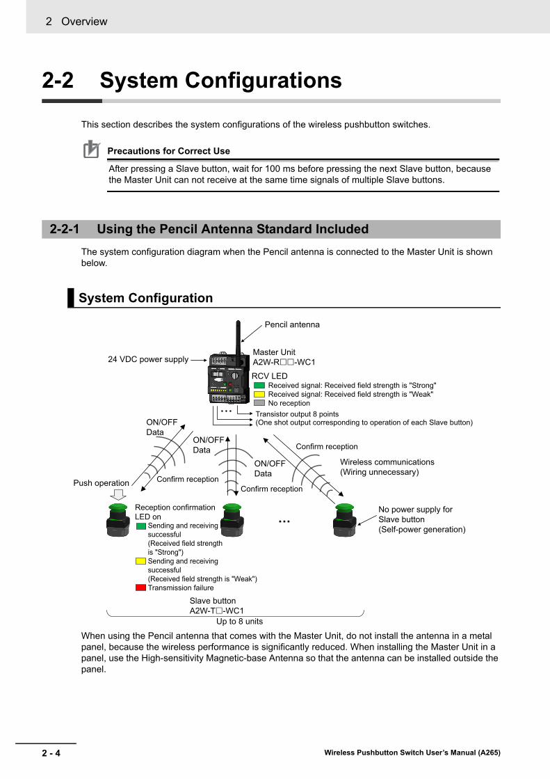
2-2 System Configurations
This section describes the system configurations of the wireless pushbutton switches.
Precautions for Correct Use
After pressing a Slave button, wait for 100 ms before pressing the next Slave button, because the Master Unit can not receive at the same time signals of multiple Slave buttons.
The system configuration diagram when the Pencil antenna is connected to the Master Unit is shown below.
When using the Pencil antenna that comes with the Master Unit, do not install the antenna in a metal panel, because the wireless performance is significantly reduced. When installing the Master Unit in a panel, use the High-sensitivity Magnetic-base Antenna so that the antenna can be installed outside the panel.
2-2-1 Using the Pencil Antenna Standard Included
System Configuration
ON/OFFData
Push operation
Wireless communications(Wiring unnecessary)
No power supply for Slave button(Self-power generation)
Confirm receptionConfirm reception
Confirm reception
Pencil antenna
Up to 8 units
Slave buttonA2W-T-WC1
Master UnitA2W-R-WC1
RCV LEDReceived signal: Received field strength is "Strong"Received signal: Received field strength is "Weak"No reception
Transistor output 8 points(One shot output corresponding to operation of each Slave button)
Reception confirmation LED on
Sending and receiving successful(Received field strength is "Strong")Sending and receiving successful(Received field strength is "Weak")Transmission failure
24 VDC power supply
ON/OFFData
ON/OFFData

2 - 5
2 Overview
Wireless Pushbutton Switch User’s Manual (A265)
2-2 System
Co
nfig
ura
tion
s
2
2-2-2 Using O
ptional High-se
nsitivity Ma
gnetic-base Antenna
The following is a system configuration diagram when the High-sensitivity Magnetic-base Antenna is connected to the Master Unit.
2-2-2 Using Optional High-sensitivity Magnetic-base Antenna
System Configuration
High-sensitivity Magnetic-base Antenna (A2W-AT2.5-WC1)
ON/OFFData
Push operation
Wireless communications(Wiring unnecessary)
No power supply for Slave button(Self-power generation)
Confirm receptionConfirm reception
Confirm reception
Up to 8 units
Slave buttonA2W-T-WC1
Master UnitA2W-R-WC1RCV LED
Received signal: Received field strength is "Strong"Received signal: Received field strength is "Weak"No reception
Transistor output 8 points(One shot output corresponding to operation of each Slave button)
Reception confirmation LED on
Sending and receiving successful(Received field strength is "Strong")Sending and receiving successful(Received field strength is "Weak")Transmission failure
24 VDC power supply
ON/OFFData
ON/OFFData

2 Overview
2 - 6 Wireless Pushbutton Switch User’s Manual (A265)
Up to 8 Slave buttons can be assigned to one Master Unit.
A single Master Unit can output eight transistors.
• A single Slave button can be assigned to each output of the Master Unit.
• In addition, the following duplicate assignments are also possible.
(a) Multiple Slave buttons can be assigned to the same output of the Master Unit.
Observe the following precautions in this case.
If you press the Slave button successively at short intervals (i.e., within 500 ms *1), not all actions of
multiple Slave buttons pressed within 500 ms *1 will be reflected. Only the actions of the Slave but-ton pushed at the beginning is reflected in the "RCV" LED and output of the Master Unit.
*1. The default value is 500 ms. It can be changed using the Wireless Switch Support Tool. Also, the LED's light-ing time is changed according to the set value of the output ON time.
2-2-3 Relationship Between Slave Buttons and Master Unit
Confirm reception
Confirm reception
The same transistor output
Master UnitA2W-R-WC1
ON/OFF Data ON/OFF
Data
Slave buttonA2W-T-WC1
2 - 7
2 Overview
Wireless Pushbutton Switch User’s Manual (A265)
2-2 System
Co
nfig
ura
tion
s
2
2-2-3 Relationship B
etween S
lave Buttons and M
aster Unit
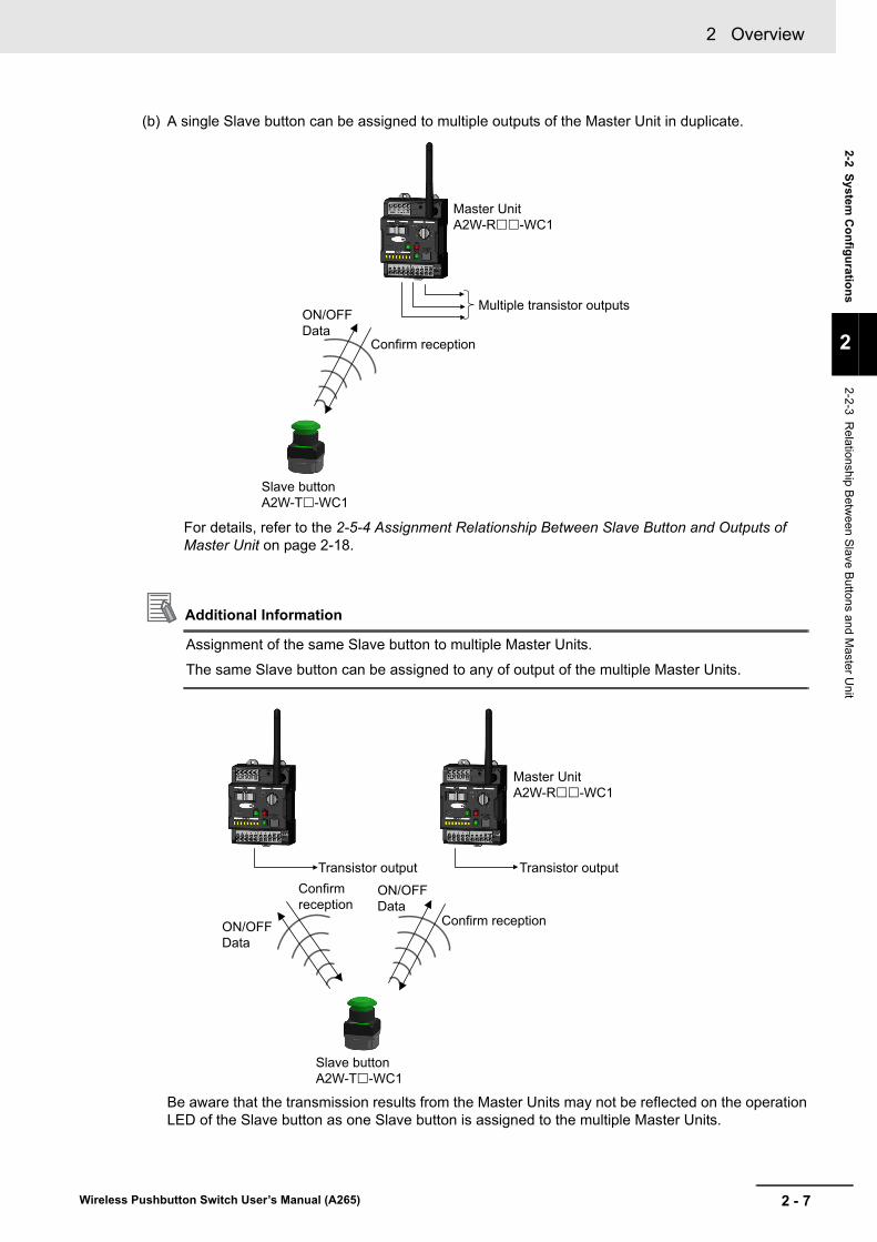
(b) A single Slave button can be assigned to multiple outputs of the Master Unit in duplicate.
For details, refer to the 2-5-4 Assignment Relationship Between Slave Button and Outputs of Master Unit on page 2-18.
Additional Information
Assignment of the same Slave button to multiple Master Units.
The same Slave button can be assigned to any of output of the multiple Master Units.
Be aware that the transmission results from the Master Units may not be reflected on the operation LED of the Slave button as one Slave button is assigned to the multiple Master Units.
Master UnitA2W-R-WC1
Slave buttonA2W-T-WC1
Confirm reception
Multiple transistor outputs ON/OFFData
Master UnitA2W-R-WC1
Slave buttonA2W-T-WC1
Transistor outputConfirm reception
Confirm reception
Transistor output
ON/OFF Data
ON/OFF Data

2 Overview
2 - 8 Wireless Pushbutton Switch User’s Manual (A265)
2-3 List of Models
This section shows models of the components of the wireless pushbutton switches system and its option.
*1. 50 to 1000 ms (It can be changed using the Wireless Switch Support Tool.)
Note Be sure to use the models for the corresponding area. When used in a country other than the correspond-ing area, it becomes illegal under the radio law of each country.
2-3-1 Master Unit and Option
Master Unit
Model Name Specifications
A2W--WC Master Unit • Wireless communications reception from up to eight Slave buttons
• Eight transistor outputs of one shot (500 ms *1)
• Power supply: 24 VDC
• One label sheet included
Number Type Symbol Specifications
(1) --- R Master Unit
(2) Frequency A 929.2 MHz
B 868.3 MHz
C 922.5 MHz
(3) Output Configuration N Sinking output
P Sourcing output
(4) Protocol 1 OMRON's protocol
(5) Area JP Japan
US United States or Canada
MX Mexico
EU Europe (EU)
BR Brazil
Option (sold separately)
Model Name Usage
A2W-AT2.5-WC1 High-sensitivity Magnetic-base Antenna
• For antenna draw out to outside the panel
• Frequency: All frequency supported
• Cable length: 2.5 m
E58-CIFQ2 USB - Serial Conversion Cable
Cable for connecting the A2W-R-WC1 to your com-puter when using the Wireless Switch Support Tool
E58-CIFQ2-E Conversion Cable
A2W- - WC (1) (2) (3) (4) (5)

2 - 9
2 Overview
Wireless Pushbutton Switch User’s Manual (A265)
2-3 Lis
t of M
od
els
2
2-3-2 Slave B
utton and Options
Note Be sure to use the models for the corresponding area. When used in a country other than the correspond-ing area, it becomes illegal under the radio law of each country.
2-3-2 Slave Button and Options
Slave Button
Model Name Specifications
A2W--WC Wireless Push Button (Slave button)
• When you press the button, send an ON /OFF signal to the Master Unit wirelessly.
• A single built-in operation LED for confirming wire-less operation to the Master Unit
• Unnecessary power supply for Slave button (self-generated by button operation)
Number Type Symbol Specifications
(1) --- T Slave button
(2) Frequency A 929.2 MHz
B 868.3 MHz
C 922.5 MHz
(3) Protocol 1 OMRON’s protocol
(4) Area JP Japan
US United States or Canada
MX Mexico
EU Europe (EU)
BR Brazil
(5) Button appearance 1 Mushroom
2 Full guard
(6) Button color R Red
G Green
Y Yellow
A Blue
W White
B Black
(7) Flange color R Red
Y Yellow
B Black
Options (sold separately)
Model Name Usage
A2W-H-WC1 Slave button holder
For installation use
A2W-S-WC1 Slave button strap
For portable use
A2W- - WC (1) (2) (3) (4) (5) (6) (7)

2 Overview
2 - 10 Wireless Pushbutton Switch User’s Manual (A265)
2-4 Nomenclature and Functions
This section describes the nomenclature and functions of the Master Unit and Slave buttons of the wire-less pushbutton switches system.
2-4-1 Master Unit
Nomenclature
NumberTerminal
nameName Function
24 VDC Power supply termi-nals
Supply 24 VDC.
24 VDC
0 V 1
0 V 2
CLR Error clear terminal Short to 0 V terminal when resetting the error output.
OUT 1 Output terminals Connect the output signal line.
There are two types of output: sinking and sourcing as flows.
• A2W-RN-WC1: Sinking output
• A2W-RP-WC1: Sourcing output
OUT 2
OUT 3
OUT 4
OUT 5
OUT 6
OUT 7
OUT 8
ERR Error output terminal Connect the error output signal line.
There are two output types: sinking and sourcing.
• A2W-RN-WC1: Sinking Outputs
• A2W-RP-WC1: Sourcing Outputs
COM Common terminal for outputs
Used as common for output and error output.
--- Antenna terminal Connect the included pencil antenna.(Optional antenna A2W-AT2.5-WC1 can also be connected.)It transmits and receives data by wireless communications via the antenna.
A B C D E
F G H I J K M N OL
S
T
W
Q P
V
U
R
Y
X
A
B
C
D
E
F
G
H
I
J
K
L
M
N
O
P

2 - 11
2 Overview
Wireless Pushbutton Switch User’s Manual (A265)
2-4 No
men
clature an
d F
un
ctio
ns
2
2-4-1 Ma
ster Unit
--- Reset switch • Delete the Slave button registration information corresponding to the output settings switch.
• By pressing the output settings switch in the "ERR CLR" state when an error output is generated, error output will be reset.
• When the power is turned ON in the pressed state, it is reset to the factory setting.
--- Output settings switch
Used to register or delete the ID of the Slave button to or from the output of the Master Unit.Also used to reset the error output without using the error clear terminal.
--- Mode settings switch Set the operation mode of the Master Unit to ID mode, TEST mode, and RUN mode.
--- Power supply LED Lit green when the power is ON.
--- Error LED Lit red when there is a possibility that abnormality occurs in the master unit and it will not output correctly according to the Slave button operation.
--- Received field strength LED
• RUN mode, or TEST mode
It lights according to the received electric field strength of the received data.
Lit green: Received field strength is "Strong"Lit yellow: Received field strength is "Weak"
• ID registration mode
Lit green when registration or deletion is success.Flashing green when registration or deletion is failure.
• When error output occurs
Lit green when the Master Unit setting data error is detected.Lit yellow when there is a possibility that the Master Unit will not output properly according to the Slave button operation.
--- Output LED • RUN mode
When outputting to the output terminal, the corresponding output LED lit yellow.
• TEST mode
It does not output to the output terminal, and the corresponding output LED lit yellow.
• ID mode
The output LED corresponding to the output setting switch lit yellow.
--- Port for the support tool Connect the E58-CIFQ2-E when using the Wireless Switch Support Tool.
--- Location to stick the label sheet
Location to stick when using the label sheet included in the Master Unit.
Display
LED name
ColorEnabled
modeStatus Meaning
PWR Green Always enabled
Lit During Power Supply
Not lit No power supplied
RCV Green or Yel-low
RUN/TEST Lit/Not lit Received field strength monitor:
Lit green: Received field strength is "Strong" (lit up for 500 msec *1)
Lit yellow: Received field strength is "Weak" (lit up for 500 msec *1)
Not lit: No received
ID Lit/Not lit/Flashing
ID registration:
Lit green: ID registration successful (lit up for 3 s)
Not lit: Data for ID registration not received
Flashing green: ID registration failed (flashes for 3 s after every 250 ms)
Delete ID:
Lit green: ID deletion successful (lit up for 3 s)
Not lit: Data for ID deletion not received
Flashing green: ID deletion failed (flashes for 3 s after every 250 ms)
Enabled only when ERR LED is lit
Lit/Not lit Lit green: Error in Master Unit setting data
Lit yellow: Error in the most important function (wireless received, registration/verification, or output)
All not lit: Error in CPU initialization process during startup
*1. The default value is 500 ms. The LED's lighting time is changed according to the set value of the output ON time.
NumberTerminal
nameName Function
Q
R
S
T
U
V
W
X
Y

2 Overview
2 - 12 Wireless Pushbutton Switch User’s Manual (A265)
Each State Corresponding to the Combination of "ERR" LED and "RCV" LED
In the RUN Mode or the TEST Mode
ID Mode
Note The strength of receiving field (RCV) will also flash green even if you select an output number that is not registered as ID and try to erase or reset.
OUTPUT
1 to 8
Yellow RUN/TEST Lit Data is received from the ID assigned to the corresponding output
Not lit Data is not received from the ID assigned to the corresponding output
ID Lit Reads corresponding output settings switch values 1 to 8
All lit Reads output settings switch value DEL
All not lit Reads output settings switch value ERR CLR
ERR Red Always enabled
Lit Error in CPU initialization processing at startup, or in Master Unit setting data, or in the most important function (wireless received, registration/verifi-cation, or output)
Not lit No Master Unit error
ERR RCV Status
Lit red Lit green Master Unit setting data error
Lit yellow The most important function error
Not lit CPU initialization processing error
Not lit Lit green No Master Unit error and with reception.
Received field strength: “Strong”.
Lit yellow No Master Unit error and with reception.
Received field strength: "Weak".
Not lit No Master Unit error and without reception.
ERR RCV Status
Lit red Lit green Master Unit setting data error
Lit yellow The most important function error
Not lit CPU initialization processing error
Not lit Lit green No Master Unit error, and ID registration success or ID deletion success
Flashing green No Master Unit error, and ID registration failure or ID deletion failure
Not lit No Master Unit error, and no data reception for ID registration or no data reception for ID deletion
LED name
ColorEnabled
modeStatus Meaning

2 - 13
2 Overview
Wireless Pushbutton Switch User’s Manual (A265)
2-4 No
men
clature an
d F
un
ctio
ns
2
2-4-1 Ma
ster Unit
Mode Settings Switch
Set the operation mode of the Master Unit.
Factory setting: ID
Output Settings Switch
Register or delete the Slave button ID *1 for each output number of the Master Unit.
Factory setting: 1
*1. This is the identification number of the Slave button for wireless communications.
Setting Switches
Operation mode
Function
RUN Communications mode: Normal communications
TEST Test mode: Installation tests such as reception strength measurement, etc.
* There is no output from the output terminal.
ID ID mode: Register or delete Slave buttons
Number Enabled mode Other settings requirements Function
1 to 8 ID Continuous data reception within a fixed period from the Slave button to be registered
Register the ID of the target Slave button to be registered in the specified output number
Press the Reset switch (ON) Delete IDs of all Slave buttons registered in the specified output number
DEL Continuous data reception within a fixed period from the Slave button for which the regis-tration is to be deleted
Delete the ID of the Slave button to be deleted from the registration list
Press the Reset switch (ON) Delete all IDs from the registration list
ERR CLR ERR LED lit red
+
RCV LED lit yellow
Press the Reset switch (ON) Execute the software reset of the Master Unit

2 Overview
2 - 14 Wireless Pushbutton Switch User’s Manual (A265)
Precautions for Correct Use
If a Slave button are assigned to multiple Master Units, the reception confirmation LED on the Slave button will light green or yellow when transmission and reception with a Master Unit suc-ceeds.
Therefore, even if there are Master Units that failed to send and receive, you may not catch it only by the reception confirmation LED on the Slave button. Make sure that the system is kept safe even in such a case.
It is the unique identification number for each Slave button. Assign this ID to the output number of the Master Unit and register the Slave button.
2-4-2 Slave Button
Nomenclature
Reception Confirmation LED
Display color Description
Green Transmission/reception success (Strength of receiving field: Strong)
Yellow Transmission/reception success (Strength of receiving field: Weak)
Red Transmission/reception failure
Not lit Slave button malfunction (No signal transmission from the Slave button)
What is a Slave Button ID?
Slave button ID
Reception confirmation LED
Flange
Button

2 - 15
2 Overview
Wireless Pushbutton Switch User’s Manual (A265)
2-5 Sp
ecification
s and
Fu
nc
tion
s
2
2-5-1 Wireless S
pecifications
2-5 Specifications and Functions
This section shows the wireless specifications of the wireless pushbutton switches system, the Master Unit, and the Slave button.
The specifications of the radio used with the wireless pushbutton switches system are as follows.
2-5-1 Wireless Specifications
Slave button model A2W-TA-WC1 JP A2W-TB-WC1 A2W-TC-WC1
Item Master Unit model A2W-RA-WC1 JP A2W-RB-WC1 A2W-RC-WC1
Set frequency 929.2 MHz 868.3 MHz 922.5 MHz
Frequency channel 1 channel
Transmission power 1 mW max. 5 mW [e.r.p.] or less 50 mV/m max.
Wireless service area communications speed
100 kbit/s
Communications method Simplex communications
Number of wireless pushbuttons con-nected
8 max.
Communications distance (line of sight) Approx. 100 m outdoors (with the included pencil antenna)
Transmission time Approx. 3 ms (from slave button transmission to slave button reception)
Repeater function Not supported.

2 Overview
2 - 16 Wireless Pushbutton Switch User’s Manual (A265)
The ratings of the Master Unit and Slave buttons are as follows.
*1. 50 to 1000 ms (It can be changed using Wireless Switch Support Tool)
*2. For writing Master Unit number etc. for specifying the Master Unit.
2-5-2 Ratings
Master Unit
Item Specifications
Master Unit power supply
Rated voltage 24 VDC
Allowable voltage range
21.6 to 26.4VDC
Current consumption 2.4 W max.
Input current 0.1 A max.
Output rated
Output pointsOutput 8 points
One other point for error output
Output circuit shared voltage
30 VDC max.
Maximum load current 50 mA per point
Leakage current 0.1 mA max.
Residual voltage 2.0 V max.
Output logic One-shot (500 ms by default *1)
Response time 30 ms or less (from Slave button transmission to Master Unit signal output)
Number of con-nected slave buttons
8 max.
Error clear ter-minal
Residual voltage at short 1.5 V or less, ON
Leakage current 0.1 mA or less, OFF (current at short: approx. 7 mA)
Insulation resistance
20 MΩ max. (100 VDC)
Between the case and power supply terminals and all outputs termi-nals
Between all power supply terminals and all outputs terminals
Dielectric strength
1,000 VAC, 1 min.
Between the case and power supply terminals and all outputs terminals
Between all power supply terminals and all outputs terminals
Vibration resistanceFrequency: 10 to 55 Hz, half amplitude: 0.42 mm3-Directional, 120 minutes each (1 sweep, 1 min. ×120 sweeps)
Shock resistance150 m/s2
Direction of shock: 3-axis, 6 directionsShock frequency: 3 × each direction, total 18
Ambient operating temperature range -10 to +55°C (no condensation or icing)
Ambient operating humidity range 20% to 90% (no condensation)
Atmosphere No corrosive gas
Storage temperature range -40 to +70°C (no condensation or icing)
Storage humidity range 20% to 90% (no condensation)
Degree of protection IP20
Altitude 2,000 m max.
Memory protection Non-volatile memory (Number of write operations: 1,000,000)
Include One label sheet *2
Weight150 g (not including antenna)
160 g (including antenna)
MountingDIN rail mountingScrew mounting

2 - 17
2 Overview
Wireless Pushbutton Switch User’s Manual (A265)
2-5 Sp
ecification
s and
Fu
nc
tion
s
2
2-5-2 Ratin
gs
Output Circuits Diagram of the Power Supply Terminals
Output/Error output circuits diagram (sinking) Output/Error output circuits diagram (sourcing)
Slave Button
Item Specifications
Operating force 25 N max.
Number of operations 1,000,000 operations
Vibration resistance Frequency: 10 to 55 Hz, 0.75-mm single amplitude for 2 h, sweeps of 5 min.
Shock resistance 1,000 m/s2 min., 3 times each in 6 directions
Ambient operating temperature range -10 to + 55 °C (with no condensation icing)
Ambient operating humidity range 20% to 90% (with no condensation)
Atmosphere No corrosive gas
Ambient storage temperature range -40 to + 70 °C (with no condensation or icing)
Ambient storage humidity range 20% to 90% (with no condensation)
Degree of protection IP65
Altitude 2,000 m max.
Weight 100 g max.
OUT1
OUT8
ERR
COM
COM
OUT1
OUT8
ERR

2 Overview
2 - 18 Wireless Pushbutton Switch User’s Manual (A265)
The Master Unit has the following operation modes.
The operation mode can be switched by the mode settings switch of Master Unit.
All assignments can be made between 8 Slave buttons and 8 outputs of the Master Unit.
Duplicate assignment is possible. A total of 8 × 8 = 64 patterns can be assigned.
• Multiple Slave buttons can be assigned to the same output.
• The same Slave button can be assigned to multiple outputs of the Master Unit.
• The above combinations are also possible.
Examples of various assignments are shown below.
For additional reference information, the ladder diagram circuit equivalent to the OR logic is shown on the right side.
In the above example, when operating either of Slave button (a), (b), or (c) once, the No.2 output will be outputted in one shot.
2-5-3 Operation Mode
Operation mode Mode name Function
RUN Communications mode
Receives data from the Slave button and performs transistor output. (During normal operation)
TEST Test mode Even if data is received from the Slave button, transistor output is not performed. (During testing)
ID ID mode Register or delete the Slave button ID. (When setting)
2-5-4 Assignment Relationship Between Slave Button and Outputs of Master Unit
Multiple Slave Buttons Are Assigned to the Same Output
Master Unit
Slave buttons
(b)(a) (c)
Input(a)
(b)
(c)
Output No. 2
Example: Three Slave button (a), (b), and (c) are assigned to the same output No. 2.
Output No. 2

2 - 19
2 Overview
Wireless Pushbutton Switch User’s Manual (A265)
2-5 Sp
ecification
s and
Fu
nc
tion
s
2
2-5-4 Assignm
ent R
elationship B
etween
Slave B
utton and O
utputs o
f Maste
r Unit
In the above example, when operating one Slave button (a) once, the No.2, No.3 and No.4 outputs will be outputted in one shot.
In the above example, when operating one Slave button (a) once, the No.2, No.3 and No.4 outputs will be outputted in one shot.
Also, when operating either of Slave button (b) or (c) once, the No.2 output will be outputted in one shot.
One Slave Button is Assigned to Two or More Outputs
Combinations of Above
Output No. 2Output No. 3Output No. 4
Master Unit
Slave Button
(a)
Input(a)
Example: Slave button (a) is assigned to output No. 2, 3, 4
Output No. 2
Output No. 3
Output No. 4
(a) (b) (c) (b)
Example: Slave button (a) is assigned
to output No. 2, 3 and 4.Slave button (b) is assigned
to output No. 2.Slave button (c) is assigned
to output No. 2.
Output No. 2Output No. 3Output No. 4
Master Unit
Slave Buttons
Output No. 2
Output No. 3
Output No. 4
Output No. 2
Input(a)
(c)

2 Overview
2 - 20 Wireless Pushbutton Switch User’s Manual (A265)

3 - 1
3
Wireless Pushbutton Switch User’s Manual (A265)
This section describes how to check the operating environment of the wireless push-button switches system. Also, Wireless Switch Support Tool allows you to investigate the radio field strength around the Master Unit. Refer to "Wireless Switch Support Tool Operation Manual (A276-E1)" when using Wire-less Switch Support Tool.
3-1 Installation and Operating Environment . . . . . . . . . . . . . . . . . . . . . . . . . . . 3-2
3-2 Operation Timing Chart . . . . . . . . . . . . . . . . . . . . . . . . . . . . . . . . . . . . . . . . . 3-53-2-1 Operation Timing Chart . . . . . . . . . . . . . . . . . . . . . . . . . . . . . . . . . . . . . . . . . . . 3-5
Survey of the Operating Environ-ment and System Design

3 Survey of the Operating Environment and System Design
3 - 2 Wireless Pushbutton Switch User’s Manual (A265)
3-1 Installation and Operating Environ-ment
This section describes the installation and operating environment of the wireless pushbutton switches system.
Before installing the Wireless Pushbutton switches System, make sure to confirm that the radio ware condition at the installation site is good by temporarily installing.
WARNINGDo not use this product without a protection circuit. Otherwise it may result in heavy injuries or damage on life or property due to malfunction.
Dual or triple safety protection circuits, such as emergency stop, interlock, or limit circuit, must be configured by external control circuit so that the system should operate on safe side even if a failure of this product or an error due to an external factor occurred.
This product is used radio waves for communications, communications may be interrupted. Depending on the surrounding environment and usage, leading to serious accidents such as severe personal injury and serious physical damage.
Safety of the system must be maintained even in such a case. In particular, this product may be disturbed by wireless systems generating strong radio waves in the neighboring frequency band. Before starting actual operation or periodically, always perform the communications test in advance and make sure that the system operates normally before using it.
Never use this product for real-time control applications.
Communications errors cause information to be delayed or missing in which may result in seri-ous accidents.
Do not use this product close to any medical equipment such as a pacemaker as it may affect operation of such medical equipment and may result in heavy injuries.

3 - 3
3 Survey of the Operating Environment and System Design
Wireless Pushbutton Switch User’s Manual (A265)
3-1 Installa
tion
and
Op
erating
En
viron
men
t
3
When selecting the installation locations of the Master Units, consider the following conditions:
• 24 VDC power supply can be supplied to the Master Unit
• To set the Master Unit at a relatively high position. When installing the Master Unit on the floor, the communications distance becomes short.
• Installation at a higher position will be installed in a more open space. As a result, radio waves will be more easily reachable without being affected by obstacles.
• Do not place a metal object around the antenna.
Metal objects reflect radio waves, so if there is a metal object around the antenna, the radio waves in a specific direction may become weak.
Keep the antenna away from the metal object.
Installation Locations
Install wireless Units as high as possible
Radio energy
Obstacles
etc.
Metal object Metal object
NG OK
Metal object Metal object
NG OK

3 Survey of the Operating Environment and System Design
3 - 4 Wireless Pushbutton Switch User’s Manual (A265)
• Floor and ceiling metal plates and piping
• Metal shielding (iron door, metallic shutter, etc.)
• Thermal insulation (cover with aluminum vapor deposition)
• People (moisture)
• Reinforced concrete wall
• Elevator
• Stainless steel cupboard and refrigerator in kitchen
• Steel shelves, lockers, etc.
• Power cable
• Window with iron wire
Do not install in the following place.
• Places exposed to direct sunlight.
• Where the humidity is very high.
• Near devices that transmit and receive radio waves such as television, radio, transceiver.
• Places close to mobile phone base station.
• Near the thing that sparks such as motor, drill, welder etc.
• Near the strong magnet.
• Near the fluorescent light.
• It is a place surrounded by metal belonging to the genus, concrete.
Additional Information
• Metal reflects radio waves. Therefore, if there is a metal object around the antenna, the radio waves in a specific direction weaken.
• Water absorbs radio waves. Therefore, if there is water in the communications path, the radio wave attenuates and weakens.
Major Radio Wave Obstacles in the Buildings
3 - 5
3 Survey of the Operating Environment and System Design
Wireless Pushbutton Switch User’s Manual (A265)
3-2 Op
eration
Tim
ing
Ch
art
3
3-2-1 Operation
Tim
ing C
hart
3-2 Operation Timing Chart
This section describes the operation timing between the Master Unit and the Slave buttons of the wire-less pushbutton switches system.
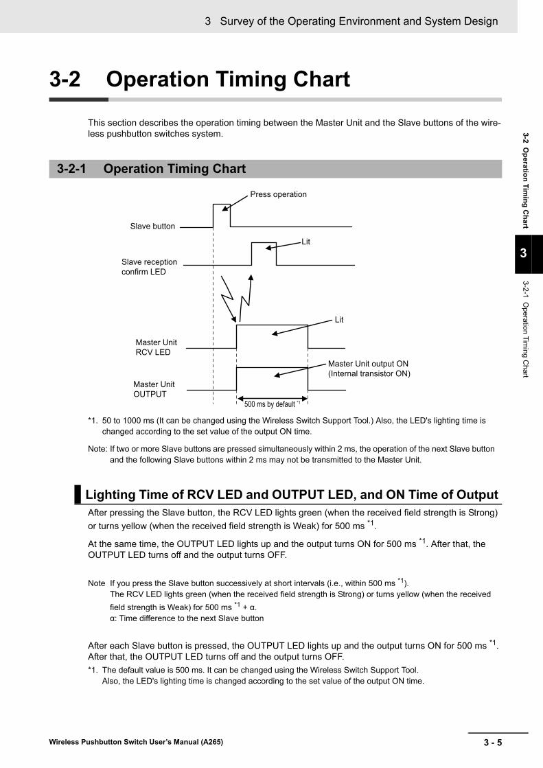
*1. 50 to 1000 ms (It can be changed using the Wireless Switch Support Tool.) Also, the LED's lighting time is changed according to the set value of the output ON time.
Note: If two or more Slave buttons are pressed simultaneously within 2 ms, the operation of the next Slave button and the following Slave buttons within 2 ms may not be transmitted to the Master Unit.
After pressing the Slave button, the RCV LED lights green (when the received field strength is Strong)
or turns yellow (when the received field strength is Weak) for 500 ms *1.
At the same time, the OUTPUT LED lights up and the output turns ON for 500 ms *1. After that, the OUTPUT LED turns off and the output turns OFF.
Note If you press the Slave button successively at short intervals (i.e., within 500 ms *1).The RCV LED lights green (when the received field strength is Strong) or turns yellow (when the received
field strength is Weak) for 500 ms *1 + α.α: Time difference to the next Slave button
After each Slave button is pressed, the OUTPUT LED lights up and the output turns ON for 500 ms *1. After that, the OUTPUT LED turns off and the output turns OFF.
*1. The default value is 500 ms. It can be changed using the Wireless Switch Support Tool.Also, the LED's lighting time is changed according to the set value of the output ON time.
3-2-1 Operation Timing Chart
Lighting Time of RCV LED and OUTPUT LED, and ON Time of Output
500 ms by default *1
Press operation
Lit
Lit
Slave button
Slave reception confirm LED
Master Unit RCV LED
Master Unit OUTPUT
Master Unit output ON (Internal transistor ON)

3 Survey of the Operating Environment and System Design
3 - 6 Wireless Pushbutton Switch User’s Manual (A265)

4 - 1
4
Wireless Pushbutton Switch User’s Manual (A265)
This section describes installation and wiring of the wireless pushbutton switch.
4-1 Dimensions . . . . . . . . . . . . . . . . . . . . . . . . . . . . . . . . . . . . . . . . . . . . . . . . . . . 4-24-1-1 Master Unit . . . . . . . . . . . . . . . . . . . . . . . . . . . . . . . . . . . . . . . . . . . . . . . . . . . . 4-2
4-1-2 Slave button . . . . . . . . . . . . . . . . . . . . . . . . . . . . . . . . . . . . . . . . . . . . . . . . . . . 4-4
4-2 Installing Master Units . . . . . . . . . . . . . . . . . . . . . . . . . . . . . . . . . . . . . . . . . . 4-64-2-1 DIN Rail Installation . . . . . . . . . . . . . . . . . . . . . . . . . . . . . . . . . . . . . . . . . . . . . 4-6
4-2-2 Screw Mounting . . . . . . . . . . . . . . . . . . . . . . . . . . . . . . . . . . . . . . . . . . . . . . . . 4-8
4-2-3 Using the Magnetic-base Antenna . . . . . . . . . . . . . . . . . . . . . . . . . . . . . . . . . . 4-8
4-3 Connecting Wires to Push-In Plus Terminal Block . . . . . . . . . . . . . . . . . . . 4-94-3-1 Terminal Blocks of the Master Unit . . . . . . . . . . . . . . . . . . . . . . . . . . . . . . . . . . 4-9
4-3-2 Push-In Plus Terminal Block . . . . . . . . . . . . . . . . . . . . . . . . . . . . . . . . . . . . . . 4-10
4-3-3 Nomenclature of the Push-In Plus Terminal Block and Connections . . . . . . . 4-10
4-3-4 Removing Wires from the Push-In Plus Terminal Block . . . . . . . . . . . . . . . . . .4-11
4-3-5 Recommended Ferrules and Crimp Tools . . . . . . . . . . . . . . . . . . . . . . . . . . . 4-12
4-4 I/O Wiring of the Master Units . . . . . . . . . . . . . . . . . . . . . . . . . . . . . . . . . . . 4-144-4-1 Power Supply input Wiring . . . . . . . . . . . . . . . . . . . . . . . . . . . . . . . . . . . . . . . 4-14
4-4-2 Transistor Output Wiring . . . . . . . . . . . . . . . . . . . . . . . . . . . . . . . . . . . . . . . . . 4-14
4-4-3 Wiring of Error Output . . . . . . . . . . . . . . . . . . . . . . . . . . . . . . . . . . . . . . . . . . . 4-15
Installation and Wiring of the Mas-ter Unit

4 Installation and Wiring of the Master Unit
4 - 2 Wireless Pushbutton Switch User’s Manual (A265)
4-1 Dimensions
This section describes the external dimensions of components of the wireless pushbutton switches sys-tem.
4-1-1 Master Unit
Master Unit Device
Unit: mm
70
34
5046
34.5(4.5)
(2)
5
5
(143.2)
(60.8)
* When installing the wall
94108 *
(161.5)
90
(79.1)

4 - 3
4 Installation and Wiring of the Master Unit
Wireless Pushbutton Switch User’s Manual (A265)
4-1 Dim
ensio
ns
4
4-1-1 Master U
nit
A2W-AT2.5-WC1 High-sensitivity Magnetic-base Antenna
USB - Serial Conversion Cable (E58 -CIFQ2) with the conversion cable (E58-CIFQ2-E)
Option (sold separately)
36
83±3
27 dia. ±2
3 dia.
+100 -02500
1.2 dia.
(2110)250 263 1510
USB connector(Type A plug) Serial connector
LED(SD)LED(PWR)
LED(RD)

4 Installation and Wiring of the Master Unit
4 - 4 Wireless Pushbutton Switch User’s Manual (A265)
Mushroom A2W--WC1-1
Full guard A2W--WC1-2
4-1-2 Slave button
Slave button Device
40 dia.42
42
26.5 35.2(2.5)
65 max.
Two, M3×6Fine thread
32
42
42
34.4 dia.
32
26.5 35.2(2.5)
65 max.
Two, M3×6Fine screw
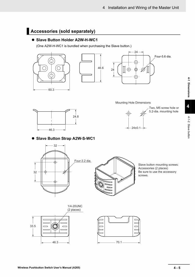
4 - 5
4 Installation and Wiring of the Master Unit
Wireless Pushbutton Switch User’s Manual (A265)
4-1 Dim
ensio
ns
4
4-1-2 Slave button
Slave Button Holder A2W-H-WC1
(One A2W-H-WC1 is bundled when purchasing the Slave button.)
Slave Button Strap A2W-S-WC1
Accessories (sold separately)
Mounting Hole Dimensions
Two, M5 screw hole or 5.2-dia. mounting hole
24±0.1
24
24.8
60.3
46.3
46.6 24
Four-5.6 dia.
32
32
33.5
46.3 70.1
1/4-20UNC (2 places)
Four-3.2 dia.Slave button mounting screws: Accessories (2 places)Be sure to use the accessory screws.
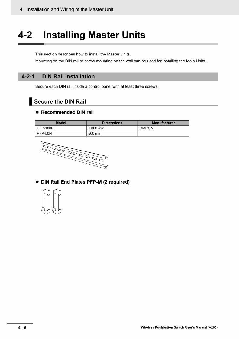
4 Installation and Wiring of the Master Unit
4 - 6 Wireless Pushbutton Switch User’s Manual (A265)
4-2 Installing Master Units
This section describes how to install the Master Units.
Mounting on the DIN rail or screw mounting on the wall can be used for installing the Main Units.
Secure each DIN rail inside a control panel with at least three screws.
Recommended DIN rail
DIN Rail End Plates PFP-M (2 required)
4-2-1 DIN Rail Installation
Secure the DIN Rail
Model Dimensions Manufacturer
PFP-100N 1,000 mm OMRON
PFP-50N 500 mm
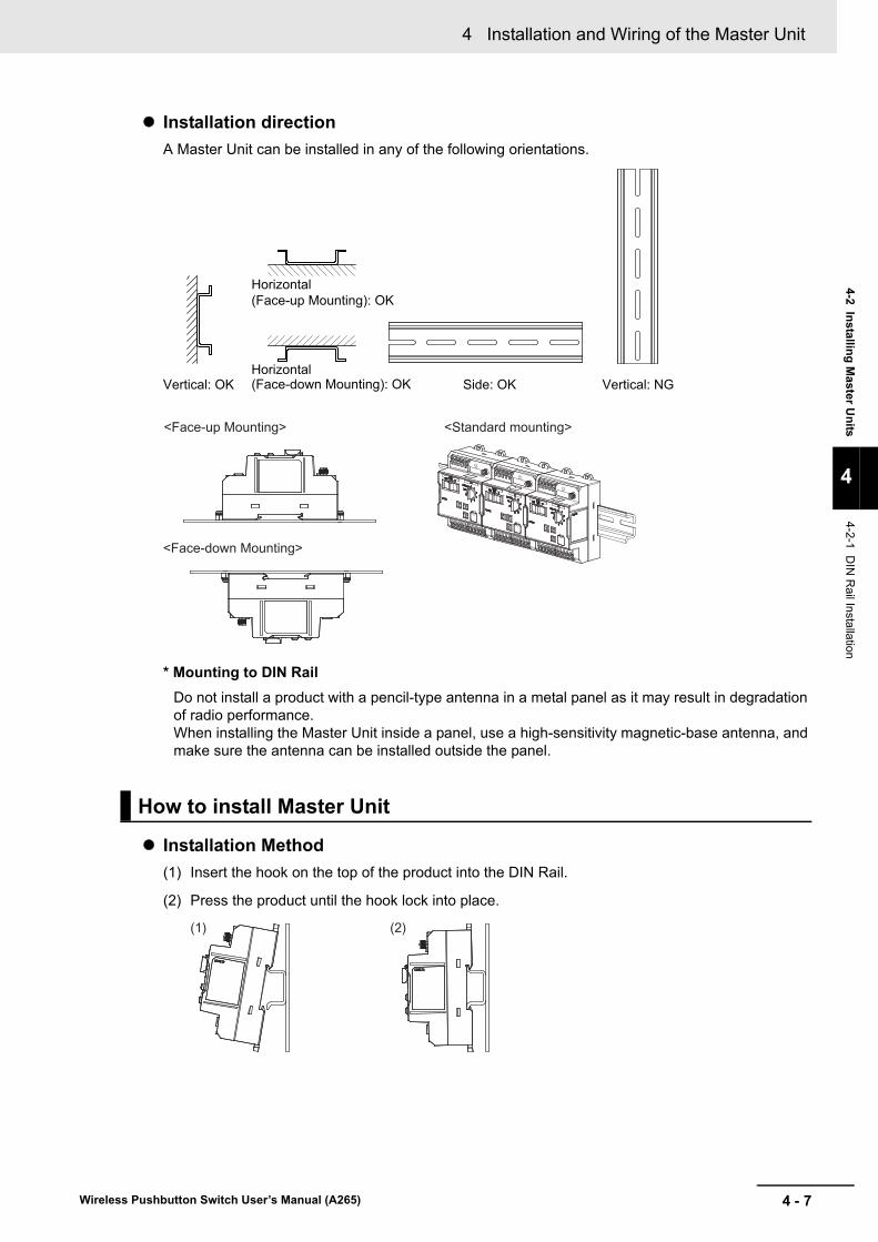
4 - 7
4 Installation and Wiring of the Master Unit
Wireless Pushbutton Switch User’s Manual (A265)
4-2 Installin
g M
aster Un
its
4
4-2-1 DIN
Rail In
stallation
Installation direction
A Master Unit can be installed in any of the following orientations.
* Mounting to DIN Rail
Do not install a product with a pencil-type antenna in a metal panel as it may result in degradation of radio performance.When installing the Master Unit inside a panel, use a high-sensitivity magnetic-base antenna, and make sure the antenna can be installed outside the panel.
Installation Method
(1) Insert the hook on the top of the product into the DIN Rail.
(2) Press the product until the hook lock into place.
How to install Master Unit
Horizontal (Face-up Mounting): OK
Horizontal (Face-down Mounting): OKVertical: OK Side: OK Vertical: NG
<Face-up Mounting> <Standard mounting>
<Face-down Mounting>
(2)(1)

4 Installation and Wiring of the Master Unit
4 - 8 Wireless Pushbutton Switch User’s Manual (A265)
Pull down on the hook with a flat-blade screwdriver and lift up on then the Master Unit.
(1) Pull out the three hooks at the back of the product toward the outside until a sound is heard.
(2) Insert M3 screws in a hole of the hooks to secure.
High-sensitivity Magnetic-base Antenna (A2W-AT2.5-WC1) of the option (sold separately) should be used when the radio environment is not good, such as when installing Master Unit inside the control panel.
Install the High-sensitivity Magnetic-base Antenna outside the control panel.
How to remove Master Unit
4-2-2 Screw Mounting
How to install Master Unit
4-2-3 Using the Magnetic-base Antenna
25 mm above
(2)(2)
(2)
(1) (1)
(1)
Inside control panel
High-sensitivity Magnetic-base Antenna
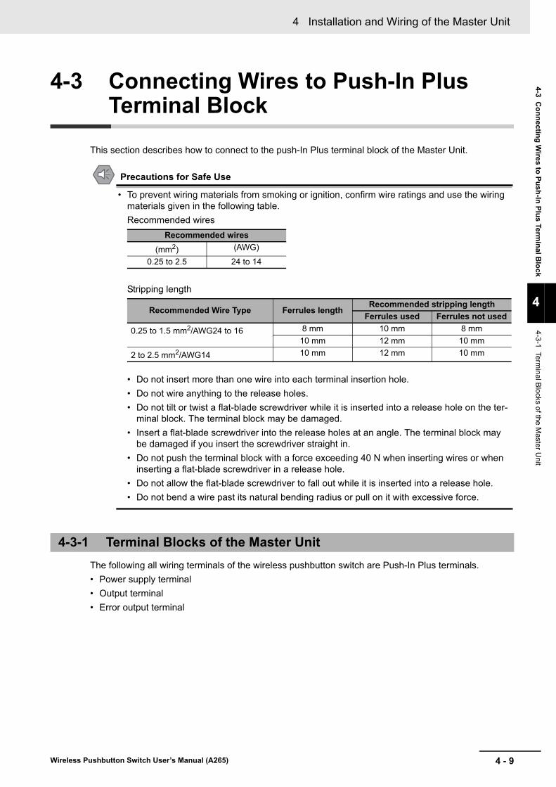
4 - 9
4 Installation and Wiring of the Master Unit
Wireless Pushbutton Switch User’s Manual (A265)
4-3 Co
nn
ecting
Wires to
Pu
sh-In
Plu
s Termin
al Blo
ck
4
4-3-1 Terminal B
locks of the Master U
nit
4-3 Connecting Wires to Push-In Plus Terminal Block
This section describes how to connect to the push-In Plus terminal block of the Master Unit.
Precautions for Safe Use
• To prevent wiring materials from smoking or ignition, confirm wire ratings and use the wiring materials given in the following table.
Recommended wires
Stripping length
• Do not insert more than one wire into each terminal insertion hole.
• Do not wire anything to the release holes.
• Do not tilt or twist a flat-blade screwdriver while it is inserted into a release hole on the ter-minal block. The terminal block may be damaged.
• Insert a flat-blade screwdriver into the release holes at an angle. The terminal block may be damaged if you insert the screwdriver straight in.
• Do not push the terminal block with a force exceeding 40 N when inserting wires or when inserting a flat-blade screwdriver in a release hole.
• Do not allow the flat-blade screwdriver to fall out while it is inserted into a release hole.
• Do not bend a wire past its natural bending radius or pull on it with excessive force.
The following all wiring terminals of the wireless pushbutton switch are Push-In Plus terminals.
• Power supply terminal
• Output terminal
• Error output terminal
Recommended wires
(mm2) (AWG)
0.25 to 2.5 24 to 14
Recommended Wire Type Ferrules lengthRecommended stripping length
Ferrules used Ferrules not used
0.25 to 1.5 mm2/AWG24 to 16 8 mm 10 mm 8 mm
10 mm 12 mm 10 mm
2 to 2.5 mm2/AWG14 10 mm 12 mm 10 mm
4-3-1 Terminal Blocks of the Master Unit
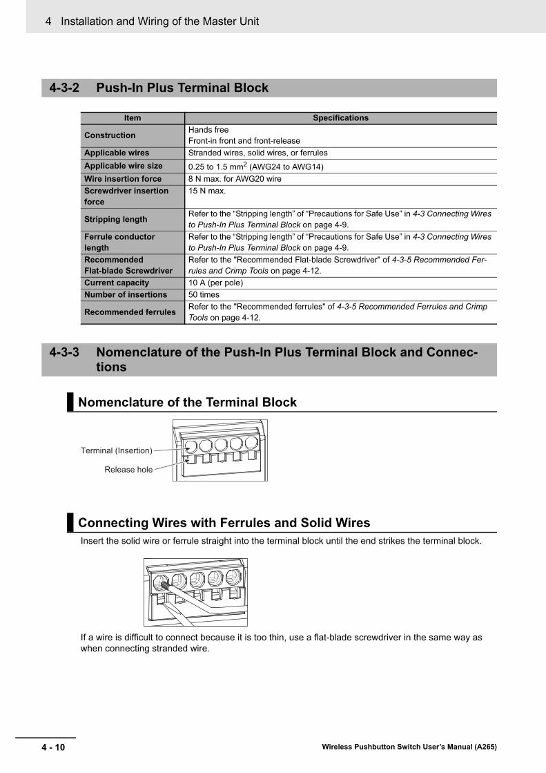
4 Installation and Wiring of the Master Unit
4 - 10 Wireless Pushbutton Switch User’s Manual (A265)
Insert the solid wire or ferrule straight into the terminal block until the end strikes the terminal block.
If a wire is difficult to connect because it is too thin, use a flat-blade screwdriver in the same way as when connecting stranded wire.
4-3-2 Push-In Plus Terminal Block
Item Specifications
ConstructionHands freeFront-in front and front-release
Applicable wires Stranded wires, solid wires, or ferrules
Applicable wire size 0.25 to 1.5 mm2 (AWG24 to AWG14)
Wire insertion force 8 N max. for AWG20 wire
Screwdriver insertion force
15 N max.
Stripping lengthRefer to the “Stripping length” of “Precautions for Safe Use” in 4-3 Connecting Wires to Push-In Plus Terminal Block on page 4-9.
Ferrule conductor length
Refer to the “Stripping length” of “Precautions for Safe Use” in 4-3 Connecting Wires to Push-In Plus Terminal Block on page 4-9.
Recommended Flat-blade Screwdriver
Refer to the "Recommended Flat-blade Screwdriver" of 4-3-5 Recommended Fer-rules and Crimp Tools on page 4-12.
Current capacity 10 A (per pole)
Number of insertions 50 times
Recommended ferrulesRefer to the "Recommended ferrules" of 4-3-5 Recommended Ferrules and Crimp Tools on page 4-12.
4-3-3 Nomenclature of the Push-In Plus Terminal Block and Connec-tions
Nomenclature of the Terminal Block
Connecting Wires with Ferrules and Solid Wires
Release hole
Terminal (Insertion)

4 - 11
4 Installation and Wiring of the Master Unit
Wireless Pushbutton Switch User’s Manual (A265)
4-3 Co
nn
ecting
Wires to
Pu
sh-In
Plu
s Termin
al Blo
ck
4
4-3-4 Rem
oving Wires from
the P
ush-In Plus Term
inal Block
Use the following procedure to connect the wires to the terminal block.
1 Hold a flat-blade screwdriver at an angle and insert it into the release hole.
The angle should be between 10° and 15°. If the flat-blade screwdriver is inserted correctly, you will feel the spring in the release hole.
2 With the flat-blade screwdriver still inserted into the release hole, insert the wire into the terminal hole until it strikes the terminal block.
3 Remove the flat-blade screwdriver from the release hole.
• After the insertion, pull gently on the wire to make sure that it will not come off and the wire is securely fastened to the terminal block.
• To prevent short circuits, insert the stripped part of a stranded or solid wire or the conductor part of a ferrule until it is hidden inside the terminal insertion hole.
Use the following procedure to remove wires from the terminal block.
The same method is used to remove stranded wires, solid wires, and ferrules.
1 Hold a flat-blade screwdriver at an angle and insert it into the release hole.
2 With the flat-blade screwdriver still inserted into the release hole, remove the wire from the ter-minal insertion hole.
3 Remove the flat-blade screwdriver from the release hole.
Connecting Stranded Wires
Checking Connections
4-3-4 Removing Wires from the Push-In Plus Terminal Block
Flat-blade screwdriver
10 to 15 ° 2
1 3
2
1 3Flat-blade screwdriver
10 to 15 °

4 Installation and Wiring of the Master Unit
4 - 12 Wireless Pushbutton Switch User’s Manual (A265)
Note 1. Make sure that the outer diameter of the wire coating is smaller than the inner diameter of the insula-tion sleeve of the recommended ferrule.
2. Make sure that the ferrule processing dimensions conform to the following figures.
4-3-5 Recommended Ferrules and Crimp Tools
Recommended ferrules
Applicable wire Ferrule Conduc-
tor length (mm)
Stripping length (mm)
(Ferrules used)
Recommended ferrules
(mm2) AWGManufactured by Phoenix Contact
Manufactured by Weidmuller
Manufactured by Wago
0.25 24 8 10 AI 0,25-8 H0.25/12 FE-0.25-8N-YE
10 12 AI 0,25-10 --- ---
0.34 22 8 10 AI 0,34-8 H0.34/12 FE-0.34-8N-TQ
10 12 AI 0,34-10 --- ---
0.5 20 8 10 AI 0,5-8 H0.5/14 FE-0.5-8N-WH
10 12 AI 0,5-10 H0.5/16 FE-0.5-10N-WH
0.75 18 8 10 AI 0,75-8 H0.75/14 FE-0.75-8N-GY
10 12 AI 0,75-10 H0.75/16 FE-0.75-10N-GY
1/1.25 18/17 8 10 AI 1-8 H1.0/14 FE-1.0-8N-RD
10 12 AI 1-10 H1.0/16 FE-1.0-10N-RD
1.25/1.5 17/16 8 10 AI 1,5-8 H1.5/14 FE-1.5-8N-BK
10 12 AI 1,5-10 H1.5/16 FE-1.5-10N-BK
2.5 14 10 12 AI 2,5-10 H2.5/16DS FE-2.5-10N-BU
Recommended crimp tool CRIMPFOX6
CRIMPFOX6T-F
CRIMPFOX10S
PZ6 roto Variocrimp4
8 to 10 mm
2.6 mm max. 2.8 mm max.

4 - 13
4 Installation and Wiring of the Master Unit
Wireless Pushbutton Switch User’s Manual (A265)
4-3 Co
nn
ecting
Wires to
Pu
sh-In
Plu
s Termin
al Blo
ck
4
4-3-5 Recom
me
nded Ferrules and C
rimp Tools
Use a flat-blade screwdriver to connect and remove wires.
Use the following flat-blade screwdriver.
The table below is the manufacturer and format as of December 2015.
Recommended Flat-blade Screwdriver
Model Manufacturer
ESD 0,40×2,5 Wera
SZS 0,4×2,5
SZF 0-0.4×2.5*1
*1. OMRON's exclusive purchase model XW4Z-00B is available to order as SZF 0-0.4 x 2.5 (manufactured by Phoenix Contact).
Phoenix Contact
0.4×2.5×75 302 Wiha
AEF.2,5×75 Facom
210-719 Wago
SDI 0.4×2.5×75 Weidmuller
Side
0.4 mm
2.5 mm dia.
2.5 mm
Front

4 Installation and Wiring of the Master Unit
4 - 14 Wireless Pushbutton Switch User’s Manual (A265)
4-4 I/O Wiring of the Master Units
This section describes how to wire the wireless pushbutton switch Master Unit.
Power must be supplied to the Master Unit.
The power input terminal is the push-in Plus terminal.
There are two terminals for 24 VDC, 0 V each. The power line can be connected to either.
The master unit has 8 transistor outputs corresponding to the Slave button.
The transistor output terminals are the Push-In Plus terminals.
*1. 50 to 1000 ms (It can be changed using the Wireless Switch Support Tool.)
4-4-1 Power Supply input Wiring
4-4-2 Transistor Output Wiring
Item Specifications
Supply voltage to the output circuit 30 VDC max.
Maximum load current 50 mA per point
Leakage current 0.1 mA max.
Residual voltage 2.0 V max.
Output logic One-shot (500 ms *1)
Power terminal Error clear terminal
(Upper left part of the Master Unit)
Output terminal Error output terminal
Transistor outputs 1 to 8Transistor output common
(Lower part of Master Unit)

4 - 15
4 Installation and Wiring of the Master Unit
Wireless Pushbutton Switch User’s Manual (A265)
4-4 I/O W
iring
of th
e Master U
nits
4
4-4-3 Wiring of E
rror Output
The master unit has one output terminal at error.
The error output terminal is the Push-In Plus terminal.
4-4-3 Wiring of Error Output
Item Specifications
Supply voltage to the output circuit 30 VDC max.
Maximum load current 50 mA per point
Leakage current 0.1 mA max.
Residual voltage 2.0 V max.
Error Output Signal
Status Internal transistor
Power is OFF OFF
Normal operation ON
Error, or momentary power failure OFF
Output contactError output terminal Error output
Transistor output common
Error outputTransistor output
(Lower part of Mater Unit)
Error output
Power ON Momentarypower failures
Continuously error
ON
OFF

4 Installation and Wiring of the Master Unit
4 - 16 Wireless Pushbutton Switch User’s Manual (A265)

5 - 1
5
Wireless Pushbutton Switch User’s Manual (A265)
This section describes how to register the Slave buttons to the Master Unit in the wire-less pushbutton switches system.Also, Wireless Switch Support Tool allows you to check the status of Slave buttons reg-istration and output assignment settings, and to change and create them.Refer to "Wireless Switch Support Tool Operation Manual (A276-E1)" when using Wire-less Switch Support Tool.
5-1 How to Register Slave Buttons to Master Unit . . . . . . . . . . . . . . . . . . . . . . 5-25-1-1 Steps to Register the Slave Buttons . . . . . . . . . . . . . . . . . . . . . . . . . . . . . . . . . 5-3
5-1-2 How to Delete Slave Buttons . . . . . . . . . . . . . . . . . . . . . . . . . . . . . . . . . . . . . . 5-5
Registration in the ID Mode

5 Registration in the ID Mode
5 - 2 Wireless Pushbutton Switch User’s Manual (A265)
5-1 How to Register Slave Buttons to Master Unit
This section describes how to register/delete the Slave buttons to/from the Master Unit.
In ID mode, you can register Slave buttons to the Master Unit.
Precautions for Correct Use
• If you register a Slave button to the Master Unit in an environment where another wireless pushbutton switch system is operating around it, it can be erroneously set. Therefore, when registering a Slave button, perform in an environment where the system of another wireless pushbutton switch is not operated.
• Register Slave buttons to one Master Unit one by one. Be sure to set the other Master Units to the RUN mode or TEST mode.
If the power of the Master Unit drops due to an instantaneous power failure or the like while registering the Slave button, the setting information may not be stored correctly in the Master Unit's memory. Then, the Master Unit may not work properly at the next startup. When registering, perform it with stable power supply status.

5 - 3
5 Registration in the ID Mode
Wireless Pushbutton Switch User’s Manual (A265)
5-1 H
ow
to R
egister S
lave Bu
tton
s to M
aster Un
it
5
5-1-1 Steps to R
egister the Slave B
uttons
Register the Slave button one by one.
Register operation is performed on both Master Unit and Slave buttons.
If you want to register multiple Slave buttons to the same output number of one Master Unit, repeat the operation for a Slave button one by one as shown below.
Operation Procedure Flowchart
5-1-1 Steps to Register the Slave Buttons
Start registration
Registration failure
Lit green
Flashing green
<Master Unit> <Slave buttons>
* Retry the operation.* Check whether the number of Slave buttons registration
to the Master Unit is over the upper limit of 8 Units.
1. Set the mode settings switch to "ID".
2. Set the output settings switch to "1", for example.
3. The output LED (example: OUTPUT 1) lights in yellow.
4. Press the pushbutton three times.
5. RCV LED arrives.
6. Completion of registration

5 Registration in the ID Mode
5 - 4 Wireless Pushbutton Switch User’s Manual (A265)
Procedure
1 Set the "mode settings switch" of the Master Unit to "ID" (ID mode).
2 Set the "output settings switch" of the Master Unit to (e.g., 1).
3 The output LED (e.g., OUTPUT 1) of the Master Unit will turn yellow.
4 Press the Slave button you want to register 3 successive times within 3 s.This assigns the ID of the Slave button to the output number of the Master Unit.
Note You can operate it more than three times.
5 The RCV LED of the Master Unit will light green for 3 s.
Note If registration fails, the Master Unit's RCV LED will flash green for 3 s.
6 Registration complete.
Mode settings switch
ID
Example 1
Output settings switch
OUTPUT 1 turns yellow.
Output LED
Operate three times within 3 s
Lit red
Slave button
RCV LED
Lit green

5 - 5
5 Registration in the ID Mode
Wireless Pushbutton Switch User’s Manual (A265)
5-1 H
ow
to R
egister S
lave Bu
tton
s to M
aster Un
it
5
5-1-2 How
to Delete S
lave B
uttons
There are three ways to delete the Slave button as follows.
Delete all Slave Buttons Together
Example: When six Slave buttons are assigned to the Master Unit, all the Slave buttons are deleted
Delete a Specific Slave Button
Example: When Slave button # 1 was assigned to Output No. 1 and 2 of the Master Unit, Slave but-ton # 1 was deleted
5-1-2 How to Delete Slave Buttons
How to delete Slave buttonsNote: Whether or not to implement
when the Slave button fails
1 Delete all Slave buttons together Possible
2 Delete a specific Slave button Not possible
3 Delete all the Slave buttons registered in the specific output num-ber of the Master Unit together
Possible
<Before deletion>
Output setting of Master Unit
<After deletion>
A Slave button assigned to the Master Unit.
Output setting of Master Unit
Everything is deleted.# 1 # 2 # 3 # 4 # 5 # 6
<Before deletion>
# 1
A Slave button registered in the Master Unit.
Output setting of Master Unit Output setting of Master Unit
<After deletion>
The Slave button #1 registered in output No. 1 and 2 are deleted.
# 2 # 3 # 4 # 2 # 3 # 4

5 Registration in the ID Mode
5 - 6 Wireless Pushbutton Switch User’s Manual (A265)
Delete All the Slave Buttons Registered in the Specific Output Together
Example: When the Slave button # 1 and # 2 are assigned to the output No. 1 of the Master Unit, the output No. 1 is deleted
Delete operation is performed only on the Master Unit side.
Operation Procedure Flowchart
Delete all Slave Buttons Together
Output setting of Master Unit
<After deletion>
Slave buttons assigned to the Master Unit The Slave buttons #1 and #2 assigned to the output No. 1 are deleted.
<Before Deletion>
# 1 # 2 # 3 # 4
Output setting of Master Unit
# 2 # 3 # 4
1. Set the mode settings switch to "ID".
2. Set the output settings switch to "DEL".
3. All output LEDs will turn yellow.
4. Push the reset switch until the RCV LED lights green for 3 s.
Delete start
< Master Unit>
5. Delete complete

5 - 7
5 Registration in the ID Mode
Wireless Pushbutton Switch User’s Manual (A265)
5-1 H
ow
to R
egister S
lave Bu
tton
s to M
aster Un
it
5
5-1-2 How
to Delete S
lave B
uttons
Procedure
1 Set the "mode setting switch" of the Master Unit to "ID" (ID mode).
2 Set the "output setting switch" of the Master Unit to ”DEL”.
3 All the output LEDs of the Master Unit will turn yellow.
4 Press and hold the Master Unit’s "Reset Switch" until the RCV LED lights green for 3 s.
5 Delete complete.
Mode settings switch
ID
DEL
Output settings switch
All LEDs turn yellow.
Output LED (OUTPUT 1 to 8)
RCV LED
Green lit for 3 s
Reset switch

5 Registration in the ID Mode
5 - 8 Wireless Pushbutton Switch User’s Manual (A265)
Delete operations are performed on both the Master Unit side and the specific Slave button. When the Slave button to delete is assigned to multiple output numbers of the Master Unit, Slave buttons are deleted from multiple output numbers at once.
Operation Procedure Flowchart
Delete a Specific Slave Button
1. Set the mode settings switch to "ID".
2. Set the output settings switch to "DEL".
3. All output LEDs will turn yellow.
Delete start
< Master Unit> < Slave buttons>
6. Delete complete
4. Press the pushbutton three times.
5. The RCV LED is turned.
Deletion failure
Lit green
Flashinggreen
* Retry the operation.* Confirm that the Slave button to be deleted is registered in the
Master Unit (it is not originally registered in the Master Unit).

5 - 9
5 Registration in the ID Mode
Wireless Pushbutton Switch User’s Manual (A265)
5-1 H
ow
to R
egister S
lave Bu
tton
s to M
aster Un
it
5
5-1-2 How
to Delete S
lave B
uttons
Procedure
1 Set the "mode settings switch" of the Master Unit to "ID" (ID mode).
2 Set the "output settings switch" of the Master Unit to ”DEL”.
3 All the output LEDs of the Master Unit will turn yellow.
4 Press the Slave button you want to delete 3 successive times within 3 s.
Note You can operate it more than three times.
5 The RCV LED of the Master Unit will light green for 3 s.
6 Delete complete.
Mode settings switch
ID
DEL
Output settings switch
All LEDs turn yellow.
Output LED (OUTPUT 1 to 8)
Operate three times within 3 s
Lit red
Slave button
RCV LED
Lit green

5 Registration in the ID Mode
5 - 10 Wireless Pushbutton Switch User’s Manual (A265)
Delete operation is performed only on the Master Unit side.
When multiple Slave buttons are registered in the output No. of the Master Unit to be deleted, multiple Slave buttons are deleted together.
Operation Procedure Flowchart
Delete ALL the Slave Buttons Registered to the Specific Output Together
RCV LED does not light green.
The RCV LED lights green for 3 s.
1. Set the mode settings switch to "ID".
Delete start
< Master Unit>
2. Set the output settings switch to "1", for example.
3. The output LED (example: OUTPUT 1) lights in yellow.
4. Press and hold the reset switch.
5. Delete complete Deletion failure
* Retry the operation* Check whether it is registered in the Slave button as the
output No. to be deleted (originally, the Slave button is not registered in the output No.).

5 - 11
5 Registration in the ID Mode
Wireless Pushbutton Switch User’s Manual (A265)
5-1 H
ow
to R
egister S
lave Bu
tton
s to M
aster Un
it
5
5-1-2 How
to Delete S
lave B
uttons
Procedure
1 Set the "mode settings switch" of the Master Unit to "ID" (ID mode).
2 Set the "Output settings switch" of Master Unit to one of the ID "1" to "8" of the Slave button you want to delete.
3 The output LED (e.g., OUTPUT 1) of the Master Unit will turn yellow.
4 Continue to hold the reset switch of the Master Unit.
5 The RCV LED of the Master Unit will light green for 3 s.
6 Delete complete.
Mode settings switch
ID
Example 1
Output settings switch
OUTPUT 1 turns yellow.
Output LED
Reset switch
Lit green for 3 s.
RCV LED

5 Registration in the ID Mode
5 - 12 Wireless Pushbutton Switch User’s Manual (A265)

6 - 1
6
Wireless Pushbutton Switch User’s Manual (A265)
This section describes the wireless test execution method of the wireless pushbutton switches system.
Additional informationUsing the Wireless Switch Support Tool allows you to perform the wireless test, and it also allows you to display the reception result log and save it as a text file.Refer to "Wireless Switch Support Tool Operation Manual (A276-E1)" when using Wire-less Switch Support Tool.
6-1 Wireless Test . . . . . . . . . . . . . . . . . . . . . . . . . . . . . . . . . . . . . . . . . . . . . . . . . 6-2
Wireless Test in the TEST Mode
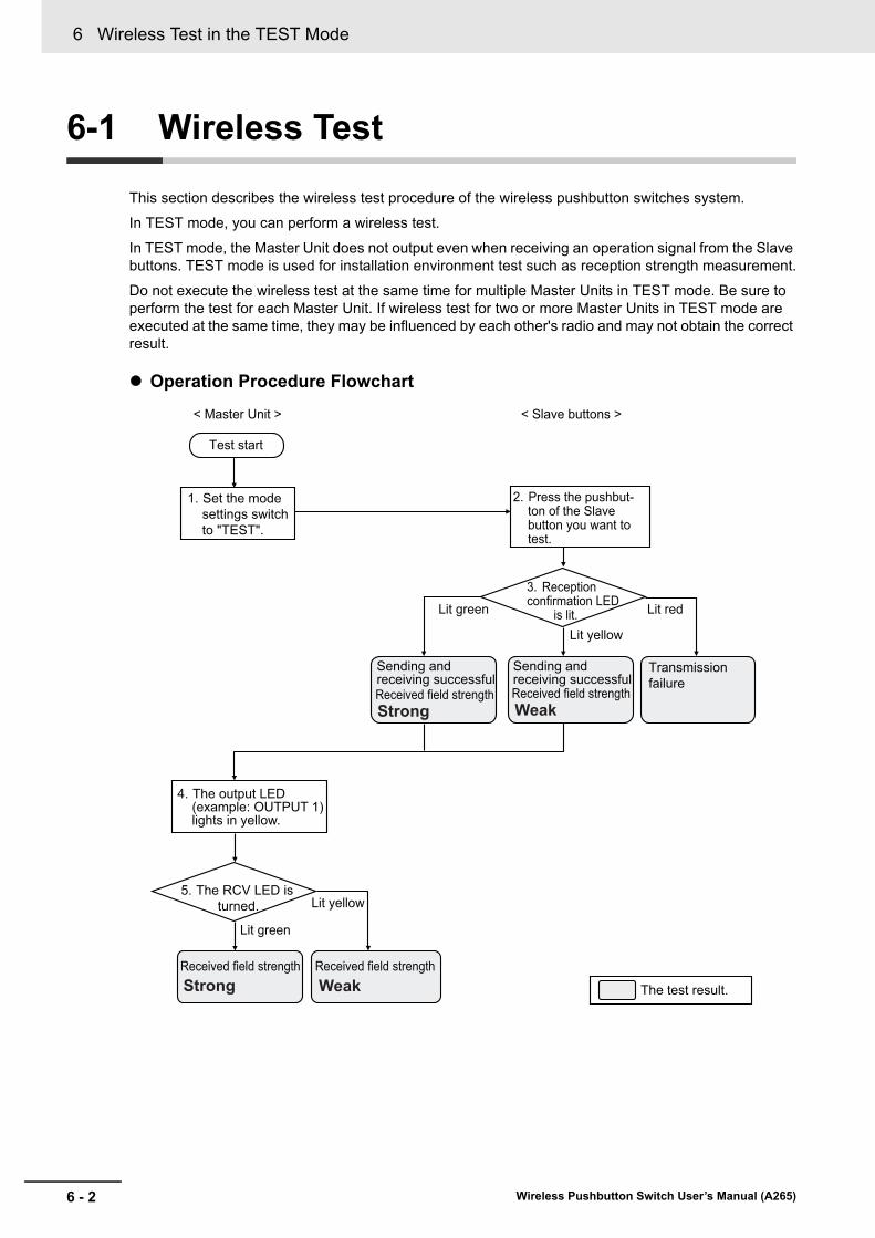
6 Wireless Test in the TEST Mode
6 - 2 Wireless Pushbutton Switch User’s Manual (A265)
6-1 Wireless Test
This section describes the wireless test procedure of the wireless pushbutton switches system.
In TEST mode, you can perform a wireless test.
In TEST mode, the Master Unit does not output even when receiving an operation signal from the Slave buttons. TEST mode is used for installation environment test such as reception strength measurement.
Do not execute the wireless test at the same time for multiple Master Units in TEST mode. Be sure to perform the test for each Master Unit. If wireless test for two or more Master Units in TEST mode are executed at the same time, they may be influenced by each other's radio and may not obtain the correct result.
Operation Procedure Flowchart
Weak
Sending and receiving successfulReceived field strength
Transmission failure
Sending and receiving successfulReceived field strength
Received field strength Received field strength
The test result.
Strong
WeakStrong
< Master Unit > < Slave buttons >
1. Set the mode settings switch to "TEST".
Test start
2. Press the pushbut-ton of the Slave button you want to test.
3. Reception confirmation LED is lit.
4. The output LED (example: OUTPUT 1) lights in yellow.
5. The RCV LED is turned. Lit yellow
Lit green
Lit green
Lit yellow
Lit red

6 - 3
6 Wireless Test in the TEST Mode
Wireless Pushbutton Switch User’s Manual (A265)
6-1 Wireless Test
6
Procedure
1 Set the "mode settings switch" of the Master Unit to "TEST" (TEST mode).
2 Press the Slave button that you want to test.
3 When the Slave button is pressed and if transmission and reception with the Master Unit is successful, the reception confirmation LED of the Slave button will light green.
Note Yellow lights up when reception sensitivity falls, and red will light when transmission or reception fails.
4 The output LED (e.g., OUTPUT 1) of the Master Unit will turn yellow for 500 ms *1. (The output number 1 of the Master Unit remains OFF.)
Mode settings switch
TEST
Slave button
Lit green.
Slave button
OUTPUT 1 turns yellow.
Output LED

6 Wireless Test in the TEST Mode
6 - 4 Wireless Pushbutton Switch User’s Manual (A265)
*1. The LED's lighting time is changed according to the set value of the output ON time.
5 When the reception field Strength is “Strong”, the RCV LED of the Master Unit will light green for 500 ms *1.When the reception field Strength is “Week”, the RCV LED of the Master Unit will light yellow for 500 ms *1.
RCV LED
Lit green: Received field strength is "Strong".Lit yellow: Received field strength is "Weak".

7 - 1
7
Wireless Pushbutton Switch User’s Manual (A265)
This section describes how to run the wireless pushbutton switches system.
7-1 Operation . . . . . . . . . . . . . . . . . . . . . . . . . . . . . . . . . . . . . . . . . . . . . . . . . . . . 7-2
Run in the RUN Mode
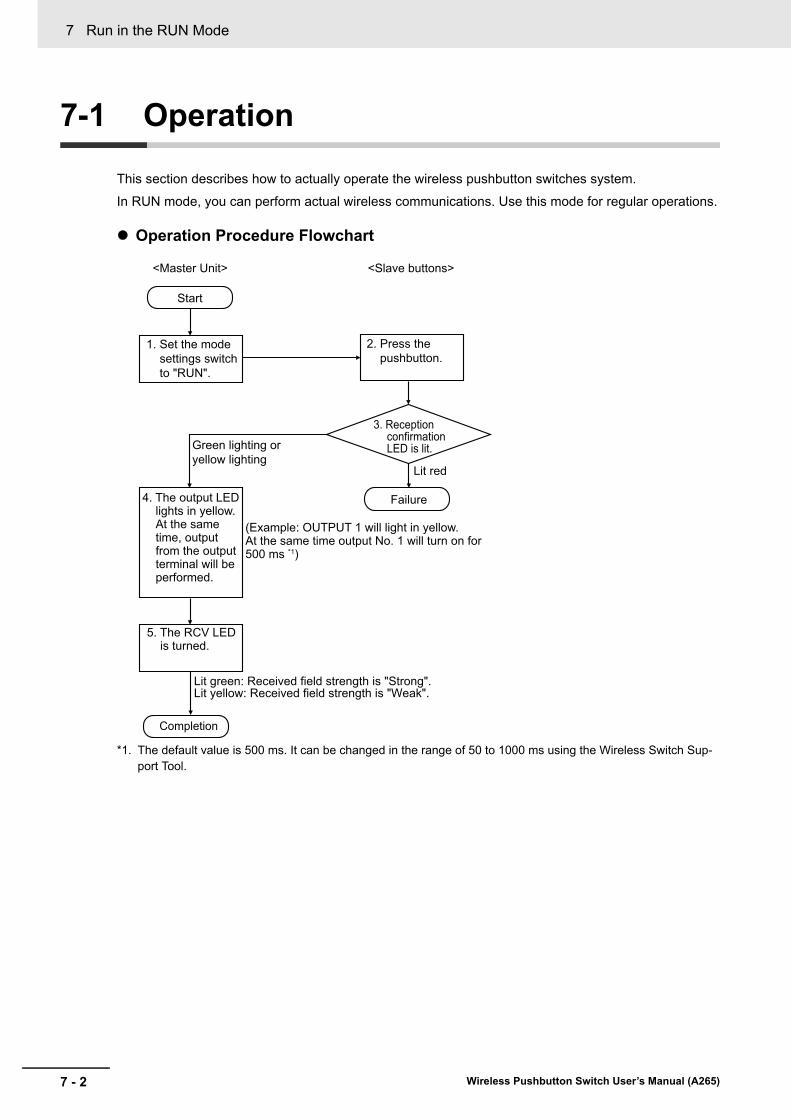
7 Run in the RUN Mode
7 - 2 Wireless Pushbutton Switch User’s Manual (A265)
7-1 Operation
This section describes how to actually operate the wireless pushbutton switches system.
In RUN mode, you can perform actual wireless communications. Use this mode for regular operations.
Operation Procedure Flowchart
*1. The default value is 500 ms. It can be changed in the range of 50 to 1000 ms using the Wireless Switch Sup-port Tool.
Start
<Master Unit>
1. Set the mode settings switch to "RUN".
2. Press the pushbutton.
<Slave buttons>
Lit red
Failure4. The output LED lights in yellow. At the same time, output from the output terminal will be performed.
5. The RCV LED is turned.
(Example: OUTPUT 1 will light in yellow.At the same time output No. 1 will turn on for 500 ms *1)
Completion
3. Reception confirmation LED is lit.
Lit green: Received field strength is "Strong".Lit yellow: Received field strength is "Weak".
Green lighting or yellow lighting

7 - 3
7 Run in the RUN Mode
Wireless Pushbutton Switch User’s Manual (A265)
7-1 Op
eration
7
Procedure
1 Set the "mode settings switch" of the Master Unit to "RUN" (RUN mode).
2 Press the Slave button registered in the Master Unit.
3 When the Slave button is pressed and if transmission and reception with the Master Unit is successful, the reception confirmation LED of the Slave button will light green.
Note Yellow lights up when reception sensitivity falls, and red will light when transmission or reception fails.
4 The output LED (e.g., OUTPUT 1) of the Master Unit will turn yellow for 500 ms *1. (The output of the Master Unit turns ON for 500 ms *1 and returns to OFF.)
Mode settings switch
RUN
Slave button
Lit green.
Slave button
OUTPUT 1 turns yellow.
Output LED

7 Run in the RUN Mode
7 - 4 Wireless Pushbutton Switch User’s Manual (A265)
*1. The default value is 500 ms. It can be changed in the range of 50 to 1000 ms using the Wireless Switch Sup-port Tool.
5 When the reception field Strength is “Strong”, the RCV LED of the Master Unit will light green for 500 ms *1.When the reception field Strength is “Week”, the RCV LED of the Master Unit will light yellow for 500 ms *1 seconds.
RCV LED
Lit green: Received field strength is "Strong".Lit yellow: Received field strength is "Weak".
8 - 1
8
Wireless Pushbutton Switch User’s Manual (A265)
i
This section describes troubleshooting when using the wireless pushbutton switches system.
8-1 Trouble Situations and How to Implement Countermeasures . . . . . . . . . . 8-28-1-1 Troubles at Installation or Operation . . . . . . . . . . . . . . . . . . . . . . . . . . . . . . . . . 8-2
8-1-2 LED Indication When Trouble Occurs . . . . . . . . . . . . . . . . . . . . . . . . . . . . . . . . 8-4
8-1-3 Cause Estimation Flow When Communications Failure Occurs . . . . . . . . . . . . 8-5
8-2 Master Unit Error . . . . . . . . . . . . . . . . . . . . . . . . . . . . . . . . . . . . . . . . . . . . . . 8-88-2-1 Error Status of the Master Unit . . . . . . . . . . . . . . . . . . . . . . . . . . . . . . . . . . . . . 8-8
8-2-2 How to Reset the Error of Master Unit . . . . . . . . . . . . . . . . . . . . . . . . . . . . . . . 8-8
8-2-3 How to Return Master Unit to Factory Setting . . . . . . . . . . . . . . . . . . . . . . . . . 8-9
8-3 Replacing Master Unit . . . . . . . . . . . . . . . . . . . . . . . . . . . . . . . . . . . . . . . . . 8-108-3-1 How to Replace Master Unit . . . . . . . . . . . . . . . . . . . . . . . . . . . . . . . . . . . . . . 8-10
Trouble Shooting

8 Trouble Shooting
8 - 2 Wireless Pushbutton Switch User’s Manual (A265)
8-1 Trouble Situations and How to Imple-ment Countermeasures
This section describes trouble situations of the wireless pushbutton switches system and how to imple-ment countermeasures.
8-1-1 Troubles at Installation or Operation
Situation Possible cause Troubleshooting methods
Master Unit’s power is not turned ON.
The power supply terminal of the Master Unit is not connected properly.
Correctly connect again.
24 VDC power is not supplied. Connect another 24 VDC supplied device instead of the Master Unit and check whether 24 VDC is supplied. If 24 VDC is supplied, the repair or replace-ment of the Master Unit is needed.
The Master Unit can not receive signals from all the Slave buttons.
The Master Unit is not correctly connected to the equipment to be controlled.
Correctly connect again.
The antenna of Master Unit is loose.
Tighten again so that there is no loose-ness.
The Master Unit can not receive a signal from a specific Slave but-ton.
The ID of the Slave button used for Master Unit is not registered.
Register the ID of the Slave button to be used in the Master Unit.
The operating frequency of the Slave button is different from one of the Master Unit.
Make the same between the Master Unit and the Slave buttons at the radio fre-quency displayed on the Master Unit device.
Signal is not being transmitted from the Slave button.
Confirm that the reception confirmation LED lights after operating the Slave but-ton. If it does not light up, replacement is necessary as the Slave button has failed.
Wireless communications are interrupted.
An object blocking radio waves was placed on the communica-tions path.
• Move the blocking object after obtain-ing permission.
• Move the installation location of Mas-ter Unit and Slave button.
A device that generates noise is nearby.
Keep the Master Unit and Slave button away from the noise source by about 1 m.
Radio waves are weak.
(Yellow LED always lit)
A Master Unit or Slave button is installed on the floor.
Install the Master Unit and Slave buttons at a relatively high position (about 1.5 m high).
There are radio wave obstacles. Keep the Master Unit and Slave buttons away from radio wave obstacles about 1 m away
The antenna is not oriented prop-erly.
Adjust the orientation of the antenna and secure it firmly.

8 - 3
8 Trouble Shooting
Wireless Pushbutton Switch User’s Manual (A265)
8-1 Tro
ub
le Situ
ation
s and
Ho
w to
Imp
lemen
t Co
un
termeasu
res
8
8-1-1 T
roubles at Installation or Operatio
n
It is in an installation environment where radio waves hardly reach.
It is installed in a building whose entire wall is covered with a metal plate.
In operating environments where radio wave obstacles can not be avoided, con-sider the communications route from the ceiling or from the window.There is a steel shelf between
Master Unit and Slave button, or it is installed on a floor where people crowd.
Despite the fact that the Master Unit is receiving a signal, the red LED on the Slave button lights up.
Temporary radio wave obstruc-tion blocked communication route.
In operating environments where radio wave obstacles can not be avoided, con-sider the communications route from the ceiling or from the window.
Equipment that generates noise intermittently is nearby.
Keep the Master Unit and Slave buttons away from the noise source by about 1 m.
The Master Unit’s power supply is turned ON again, but it does not operate normally.
The time from turning OFF the power to turning it ON is short.
To turn ON the power again after turning OFF the power, wait for 30 s or more before turning it ON.
Situation Possible cause Troubleshooting methods

8 Trouble Shooting
8 - 4 Wireless Pushbutton Switch User’s Manual (A265)
8-1-2 LED Indication When Trouble Occurs
Master Unit
PWR lighting state Status Troubleshooting methods
Not lit Power is not supplied to Master Unit.
Refer to the Master Unit’s power is not turned ON. on page 8-2 in 8-1-1 Trou-bles at Installation or Operation on page 8-2.
RCV lighting state Status Troubleshooting methods
Lit yellow after reception The reception is successful, but the radio field strength is weak.
Refer to the Radio waves are weak. on page 8-2 or It is in an installation envi-ronment where radio waves hardly reach. on page 8-3 in the 8-1-1 Troubles at Installation or Operation on page 8-2.
ERR lighting condition
RCV lit state Status Troubleshooting methods
Lit Not lit CPU initialization error at startup. Turn ON the power again.
If not improved, repair or replacement is necessary.
Lit green An error occurred writing or read-ing the setting data saved in the Master Unit.
Turn ON the power again.
If not improved, repair or replacement is necessary.
Lit yellow Data error related to wireless communications has occurred.
Perform software reset.
For the software reset method, refer to 8-2-2 How to Reset the Error of Master Unit on page 8-8.
If it is not improved, it is necessary to ini-tialize the setting information, repair or replace the setting information.
Slave button
Lit state Status Troubleshooting methods
Do not lit after operation No signal is being sent from Slave button.
Replacement is required.
Lit red after operation The Slave button failed to receive the reception confirmation signal from the Master Unit.
Refer to The Master Unit can not receive signals from all the Slave buttons. on page 8-2, The Master Unit can not receive a signal from a specific Slave button. on page 8-2, Radio waves are weak. on page 8-2, or It is in an installa-tion environment where radio waves hardly reach. on page 8-3 in the 8-1-1 Troubles at Installation or Operation on page 8-2.
Lit yellow after operation The Slave button is successful in communicating with the Master Unit, but the field strength is weak.
Refer to the Radio waves are weak. on page 8-2 or It is in an installation envi-ronment where radio waves hardly reach. on page 8-3 in the 8-1-1 Troubles at Installation or Operation on page 8-2.

8 - 5
8 Trouble Shooting
Wireless Pushbutton Switch User’s Manual (A265)
8-1 Tro
ub
le Situ
ation
s and
Ho
w to
Imp
lemen
t Co
un
termeasu
res
8
8-1-3 C
ause E
stima
tion Flo
w W
hen Com
munication
s Failure
Occurs
Estimating Causes of Communications Failure
Cause Estimation by the Communications Test Result
Perform the communications test and check the following points.
· How is time-series changes at the same Slave button?
· Whether communications failure occurs intermittently or constantly?
Or
· How is the simultaneity of multiple Slave buttons operations?
· Whether the Slave button that fails communications is a particular Slave button or all Slave but-ton?
In accordance with that, estimate "where" and "what" are causing the following communications fail-ure.
Main causes of communications failure:
• Collision or interference
• Fluctuation of installation location (i.e., extension of communications distance)
• Obstacles
• Malfunctions of the device
The following show flowcharts to identify each cause.
8-1-3 Cause Estimation Flow When Communications Failure Occurs
START
Confirm the PWR LED and the ERR LED display of the Master Unit.
Failure to supply power to the Master Unit:The following are assumed: Causes such as power supply line misconnection, Master Unit malfunction, and insufficient voltage
Master Unit malfunction:Estimate the cause based on lighting pattern of LEDs.
* The operation mode of the Master Unit must be set to TEST mode.
The Slave button failed.
Cause estimation as shown below is required based on the communications test result.
Confirm the LEDs of the Slave buttons.
Is the PWR LED not lit?
NO
YES
YES
YES
NO
NO
Is the ERR LED lit?
Is the LED not lit?

8 Trouble Shooting
8 - 6 Wireless Pushbutton Switch User’s Manual (A265)
Communications Failure Due to Collision or Interference
Communications Failure Due to the Fluctuation of Installation Location (i.e., Extension of Communications Distance)
It occurred temporarily.
START
(Cause: Location where it occurred)Around the Master Unit
(Cause: Object that caused the problem)Other systems, or existence of other switches
(Cause: Phenomenon that caused the problem)Operation timings with other switches overlap temporarily.Operating frequency of other systems temporarily increases and acts as noise.
(Cause: Location where it occurred)Around a specific Slave button, or between a specific Slave button and the Master Unit
It occurred at all Slave buttons.
(Cause: Location where it occurred)Around the Master Unit
(Cause: Object that caused the problem)Other systems, or existence of other switches
(Cause: Phenomenon that caused the problem)Simultaneous pushing with other switches occurs continuously.Other systems continuously act as noise.
(Cause: Location where it occurred)Around a specific Slave button, or between a specific Slave button and the Master Unit
It occurred at all Slave buttons.
NO
NO NOYES
YES YES
START
(Cause: Location where it occurred)Master Unit
(Cause: Location where it occurred)Master Unit itself
(Cause: Phenomenon that caused the problem)The Master Unit temporarily away from the Slave button.
(Cause: Phenomenon that caused the problem)A particular Slave button is temporarily away from the Master Unit.
(Cause: Phenomenon that caused the problem)The Master Unit temporarily away from the Slave button.
(Cause: Location where it occurred)Specific Slave button
(Cause: Location where it occurred)Particular Slave button itself
It occurred temporarily.
It occurred at all Slave buttons.
(Cause: Location where it occurred)Master Unit
(Cause: Location where it occurred)Master Unit itself
(Cause: Phenomenon that caused the problem)A particular Slave button is moving away from the Master Unit.
(Cause: Location where it occurred)Specific Slave button
(Cause: Location where it occurred)Particular Slave button itself
It occurred at all Slave buttons.
NO
NO NOYES
YES YES
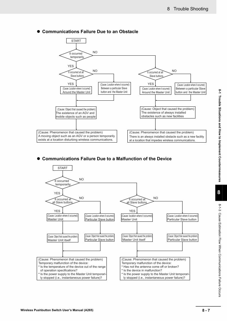
8 - 7
8 Trouble Shooting
Wireless Pushbutton Switch User’s Manual (A265)
8-1 Tro
ub
le Situ
ation
s and
Ho
w to
Imp
lemen
t Co
un
termeasu
res
8
8-1-3 C
ause E
stima
tion Flo
w W
hen Com
munication
s Failure
Occurs
Communications Failure Due to an Obstacle
Communications Failure Due to a Malfunction of the Device
START
(Cause: Location where it occurred)Around the Master Unit
(Cause: Object that caused the problem)The existence of an AGV and mobile objects such as people
(Cause: Phenomenon that caused the problem)A moving object such as an AGV or a person temporarily exists at a location disturbing wireless communications.
(Cause: Phenomenon that caused the problem)There is an always installed obstacle such as a new facility at a location that impedes wireless communications.
(Cause: Location where it occurred)Between a particular Slave button and the Master Unit
It occurred temporarily.
It occurred at all Slave buttons.
(Cause: Location where it occurred)Around the Master Unit
(Cause: Object that caused the problem)The existence of always installed obstacles such as new facilities
(Cause: Location where it occurred)Between a particular Slave button and the Master Unit
It occurred at all Slave buttons.
NO
NO NOYES
YES YES
START
(Cause: Location where it occurred)Master Unit
(Cause: Object that caused the problem)Master Unit itself
(Cause: Phenomenon that caused the problem)Temporary malfunction of the device:• Is the temperature of the device out of the range
of operation specifications?• Is the power supply to the Master Unit temporari-
ly stopped (i.e., instantaneous power failure)?
(Cause: Phenomenon that caused the problem)Temporary malfunction of the device:• Has not the antenna come off or broken?• Is the device in malfunction?• Is the power supply to the Master Unit temporari-
ly stopped (i.e., instantaneous power failure)?
(Cause: Location where it occurred)Particular Slave button
(Cause: Object that caused the problem)Particular Slave button
It occurred temporarily.
It occurred at all Slave buttons.
(Cause: location where it occurred)Master Unit
(Cause: Object that caused the problem)Master Unit itself
(Cause: Location where it occurred)Particular Slave button
(Cause: Object that caused the problem)Particular Slave button
It occurred at all Slave buttons.
NO
NO NOYES
YES YES
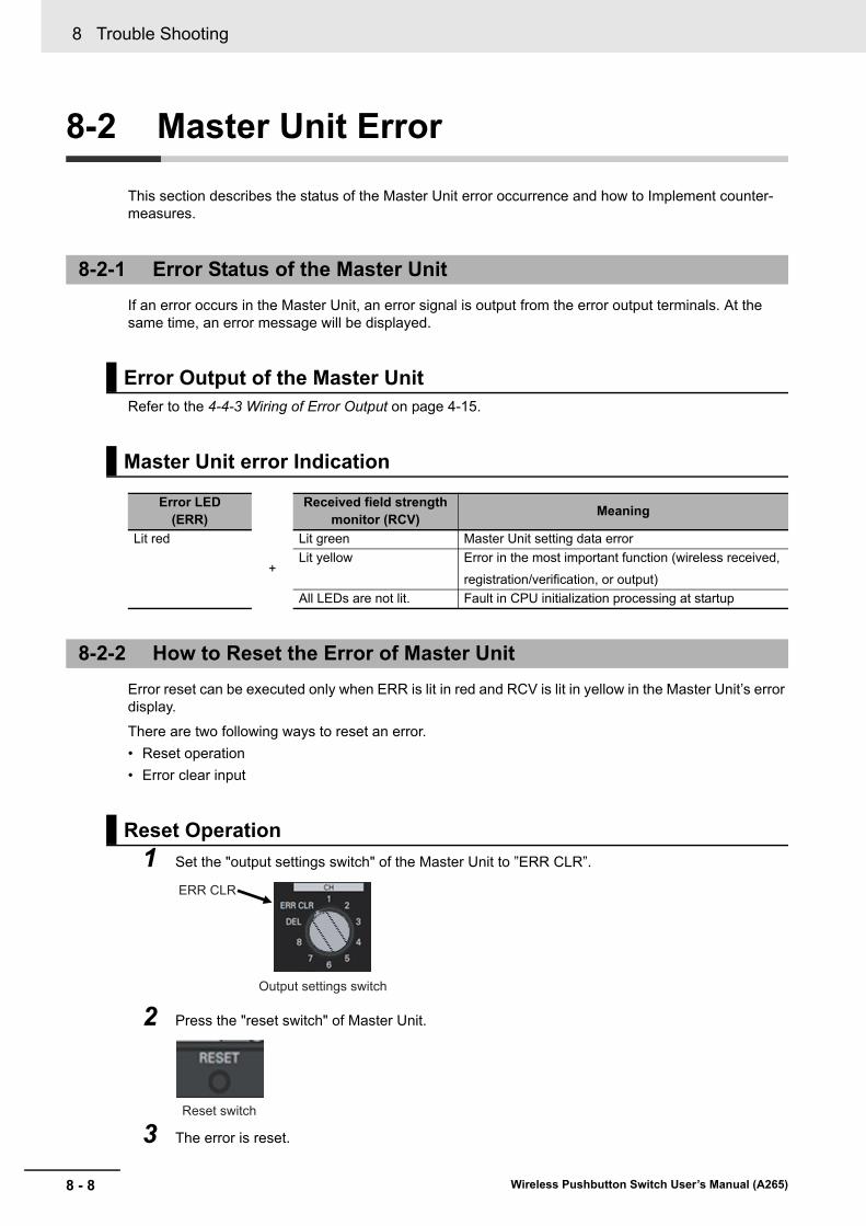
8 Trouble Shooting
8 - 8 Wireless Pushbutton Switch User’s Manual (A265)
8-2 Master Unit Error
This section describes the status of the Master Unit error occurrence and how to Implement counter-measures.
If an error occurs in the Master Unit, an error signal is output from the error output terminals. At the same time, an error message will be displayed.
Refer to the 4-4-3 Wiring of Error Output on page 4-15.
Error reset can be executed only when ERR is lit in red and RCV is lit in yellow in the Master Unit’s error display.
There are two following ways to reset an error.
• Reset operation
• Error clear input
1 Set the "output settings switch" of the Master Unit to ”ERR CLR”.
2 Press the "reset switch" of Master Unit.
3 The error is reset.
8-2-1 Error Status of the Master Unit
Error Output of the Master Unit
Master Unit error Indication
Error LED(ERR)
Received field strength monitor (RCV)
Meaning
Lit red
+
Lit green Master Unit setting data error
Lit yellow Error in the most important function (wireless received,
registration/verification, or output)
All LEDs are not lit. Fault in CPU initialization processing at startup
8-2-2 How to Reset the Error of Master Unit
Reset Operation
ERR CLR
Output settings switch
Reset switch

8 - 9
8 Trouble Shooting
Wireless Pushbutton Switch User’s Manual (A265)
8-2 Master U
nit E
rror
8
8-2-3 H
ow to R
eturn Master U
nit to Factory S
etting
1 Make short the Master Unit error clear terminal to 0 V.
The voltage between the error clear terminal and 0 V must be 15 VDC or less to reset the error.
The error clear terminal and 0 V are the Push-In Plus terminals.
2 The error is reset.
The Master Unit can be restored to the factory setting by the following method.
1 Turn OFF the power supply to the Master Unit.
2 With the reset button pressed, Turn ON power to the Master Unit again.
3 The setting information is initialized and it returns to the factory setting.
Error Clear Input
8-2-3 How to Return Master Unit to Factory Setting
(Upper left part of Master Unit)
Power supply terminals Error clear terminal

8 Trouble Shooting
8 - 10 Wireless Pushbutton Switch User’s Manual (A265)
8-3 Replacing Master Unit
This section describes how to replace the Master Unit of the wireless pushbutton switch.
1 Make a note of the current Master Unit status.
Number of Slave buttons, ID of Slave button, wiring of external output, etc.
2 Remove all Master Unit wiring.
Refer to the 4-3-4 Removing Wires from the Push-In Plus Terminal Block on page 4-11.
3 Exchange Master Unit.
Refer to the 4-2 Installing Master Units on page 4-6.
4 Connect the wiring removed in 2.
Refer to the 4-3-3 Nomenclature of the Push-In Plus Terminal Block and Connections on page 4-10 and 4-4 I/O Wiring of the Master Units on page 4-14.
5 Delete all setting of Slave button registered in Master Unit.
Refer to the 5-1-2 How to Delete Slave Buttons on page 5-5.
6 Register Slave buttons in the Master Unit.
Refer to the 5-1-1 Steps to Register the Slave Buttons on page 5-3.
7 Test wireless communications.
Refer to the 6-1 Wireless Test on page 6-2.
Note Unintended communications with other systems may occur after replacing the Master Unit. Therefore, delete all registration of Slave button in the Master Unit once. Then register the Slave buttons again. After that, make sure to execute the communications test before use.
8-3-1 How to Replace Master Unit
A - 1
A
Wireless Pushbutton Switch User’s Manual (A265)
A-1 Slave Button Registration Management Sheet . . . . . . . . . . . . . . . . . . . . . . A-2
Appendix

Appendix
A - 2 Wireless Pushbutton Switch User’s Manual (A265)
A-1 Slave Button Registration Manage-ment Sheet
Use this sheet to record the Slave buttons to be registered in the Master Unit.
Copy the next page.
For the output number of Master Unit, put a check mark in the column of the registered Slave button number. Also, to confirm the slave button, enter the ID described next to the slave button body.
<Entry example>
Slave buttonName
Line A completion switch
Line B completion switch
Master Unit Output Number
Line C completion switch
Call switchSwitch for instructing replenishment of parts
(Remarks)
Master Unit #: Name of equipment etc.:
Date: Month: Year: Organization: Name:

A - 3
Appendix
Wireless Pushbutton Switch User’s Manual (A265)
A-1 S
lave Bu
tton
Reg
istration
Man
agem
ent S
heet
A
(Remarks)
Slave buttonName
Master Unit Output Number
(Remarks)
Slave buttonName
Master Unit Output Number
(Remarks)
Slave buttonName
Master Unit Output Number
Master Unit #: Name of equipment etc.:
Date: Month: Year: Organization: Name:
Master Unit #: Name of equipment etc.:
Date: Month: Year: Organization: Name:
Master Unit #: Name of equipment etc.:
Date: Month: Year: Organization: Name:

Appendix
A - 4 Wireless Pushbutton Switch User’s Manual (A265)


Authorized Distributor:
In the interest of product improvement, specifications are subject to change without notice.
Cat. No. A265-E1-02 0418
© OMRON Corporation 2017-2018 All Rights Reserved.
OMRON Corporation Industrial Automation Company
OMRON ELECTRONICS LLC2895 Greenspoint Parkway, Suite 200 Hoffman Estates, IL 60169 U.S.A.Tel: (1) 847-843-7900/Fax: (1) 847-843-7787
Regional HeadquartersOMRON EUROPE B.V.Wegalaan 67-69, 2132 JD HoofddorpThe NetherlandsTel: (31)2356-81-300/Fax: (31)2356-81-388
Contact: www.ia.omron.comKyoto, JAPAN
OMRON ASIA PACIFIC PTE. LTD.No. 438A Alexandra Road # 05-05/08 (Lobby 2), Alexandra Technopark, Singapore 119967Tel: (65) 6835-3011/Fax: (65) 6835-2711
OMRON (CHINA) CO., LTD.Room 2211, Bank of China Tower, 200 Yin Cheng Zhong Road, PuDong New Area, Shanghai, 200120, ChinaTel: (86) 21-5037-2222/Fax: (86) 21-5037-2200