
Wireless Network Design Best Practices · Wireless Network Design – Best Practices Proxim...
17
Wireless Network Design – Best Practices © Proxim Wireless. All rights reserved.
Transcript of Wireless Network Design Best Practices · Wireless Network Design – Best Practices Proxim...

Wireless Network Design – Best Practices
© Proxim Wireless. All rights reserved.

Wireless Network Design – Best Practices
© Proxim Wireless. All rights reserved.
Regardless of the application, today wireless broadband is the order of the day, providing fiber like connectivity and reliability in a matter of hours. However, like any project, a successful wireless network deployment relies on proper
planning and design.

Wireless Network Design – Best Practices
© Proxim Wireless. All rights reserved.

Wireless Network Design – Best Practices
© Proxim Wireless. All rights reserved.
UnderstandThe first step in any network design is to clearly identify and understand all requirements and identify any constraints which might create limitations for the wireless project.
Understanding Requirements: Best PracticesIn all cases involving network design, the design and integration teams must meet with the business team to gain a clear understanding of the business requirements. The requirements must be documented and a report distributed to the teams to make sure all parties agree to the requirements. Next all constraints must be identified which include budget limitations, industry regulations, application requirements, and project timeframe. Surveys will be required to identify RF and environmental constraints and to make sure the network operator has access to potential mounting assets. Some technical factors such as mobility support often require a pilot and feasibility study. Surveys and studies must be identified and a budget, plan, and schedule put in place to deliver any project limitations and risks created by the identified constraints. A complete set of network requirements and a feasibility study are deliverables from this step in the design process.
Gathering Network RequirementsThe project requirements are defined by the business needs which create the foundation of the network and identifies the applications utilizing the network. The applications define the functional requirements and the data traffic requirements of the network. Together these elements ultimately define the network deployment along with budget, timeframe, mounting restrictions, and the traffic flows the network will support.
For example, if the network is designed to connect buildings on a campus and the traffic is mainly student data such as email, internet browsing, and social media, the network will not need to support critical prioritized traffic potentially reducing budget, allow for more flexible technology options and a better deployment timeframe.
If the network is being designed to support video surveillance, VoIP, and mobile law enforcement connectivity, then all data traffic on the network will require prioritization and the design must support 5-nines reliability, robust mobile coverage, and full traffic engineering. These requirements are potentially more costly and a very robust design is critical to a successful deployment so more time and money should be budgeted for design, equipment, and deployment.
Although the two design examples presented cover the same buildings, the data traffic and technology requirements are very different as are the associated equipment requirements, RF environmental concerns, project budget, and deployment timeframe. It may also be the case where a single network design will need to meet the requirements of both scenarios presented.
ConstraintsConstraints are project limiting factors which potentially prevent meeting all the project requirements. Constraints may include budget limitations, RF environmental factors such as line of sight or interference, and finally application restrictions such as security and access concerns. Some or all of these concerns will be present in almost every wireless network deployment so proper understanding of the requirements, technology, and environment must be in place for a successful design and network deployment to be delivered to the business.

Wireless Network Design – Best Practices
© Proxim Wireless. All rights reserved.

Wireless Network Design – Best Practices
© Proxim Wireless. All rights reserved.
Infrastructure PlanningDepending upon the network requirements and design, the infrastructure deployed will require careful consideration of both the radio and switching technology used in the wireless network. Designs using licensed and/or unlicensed frequencies, Point to Point (PtP) and/or Point to Multi-Point (PtMP) links all use different calculations and survey methods based on factors such as line of sight (LoS), distance, and capacity. These methods evaluate environmental factors, path requirements, and data requirements then match those to technical capabilities. Data traffic, application, and security requirements will also influence the technology considered and evaluated for the network.

Wireless Network Design – Best Practices
© Proxim Wireless. All rights reserved.

Wireless Network Design – Best Practices
© Proxim Wireless. All rights reserved.
Link PlanningOnce the infrastructure technology has been matched to the requirements, the next step is to design each link within the network. This step takes data from the infrastructure planning and applies it to the planning of each individual link using technology specific path calculations. Each link uses a unique calculation based on the type of technology, use of licensed or unlicensed bands, and environmental factors to calculate the capability of the link between two mounting points. The calculations must show the link is capable of meeting both the reliability and capacity requirements to be considered in the deployment. When a link calculation determines a link cannot meet the requirements, either optional mounting locations or a different technology need to be identified. This critical step in the design of the network provides the first opportunity of a successful deployment. If this step cannot be successfully completed, a new constraint has been identified and Step Two “infrastructure planning” should be repeated.
The evaluation takes into account the Line of Sight (LoS) characteristics of the link and Fresnel Zone clearance. The ideal link scenario is 100% clear LoS between the two mounting points and at least 60% of the first Fresnel Zone is clear. The longer the distance between the two end points, the more important a factor the Fresnel Zone plays.
A Fresnel Zone is described as an ellipsoid shaped area surrounding the clear line of sight and as shown above consists of multiple zones. It is important to note that the highest impact on the performance of a link is determined essentially by the first Fresnel zone and thus should be of highest interest to you.

Wireless Network Design – Best Practices
© Proxim Wireless. All rights reserved.

Wireless Network Design – Best Practices
© Proxim Wireless. All rights reserved.
Link Budget CalculationThe link budget is a calculated value indicating how resilient a link will be when dynamic RF factors have a negative impact on the performance of the link. It provides a gauge between the expected throughput and the required throughput.
The Link budget analysis typically starts with the calculation of the System Operating Margin, commonly known as fade margin, which is the difference between the signal strength a radio is actually receiving and the signal required for a reliable link with low bit errors.
This is calculated by taking into account all of the gains and losses throughout the link. An example of a Link Budget calculation is shown below and illustrates the typical gains and the losses in a wireless link system. Please be aware of the signal attenuation occurring over a distance is calculated in the FSL (free space loss) component of the Link Budget analysis which helps installers estimate the received signal strength at different distances. Typically a received signal level with a fade margin of 10-15dB is considered sufficient for an optimal performance.
Once the received signal strength is calculated, the next step is to is determine the Signal to Noise Ratio (SNR) by reading the noise level at the receiver end and subtracting it from the actual received signal strength:
SNR = Received power (dB) – Channel Noise (dB)
With the calculated SNR values, the installer can work out the modulation levels and associated link data rates using the table, as shown below, which provides a list of modulation levels and corresponding operable SNR ranges. As one can observe, higher modulation, such as 64-QAM, require higher SNR and are more vulnerable to noise and other RF interference. The lower spectral efficient modulations such as BPSK require less SNR and are therefore generally used in scenarios where the noise floor is higher and where interference is present.
Wireless Network Design – Best Practices
© Proxim Wireless. All rights reserved.

Wireless Network Design – Best Practices
© Proxim Wireless. All rights reserved.
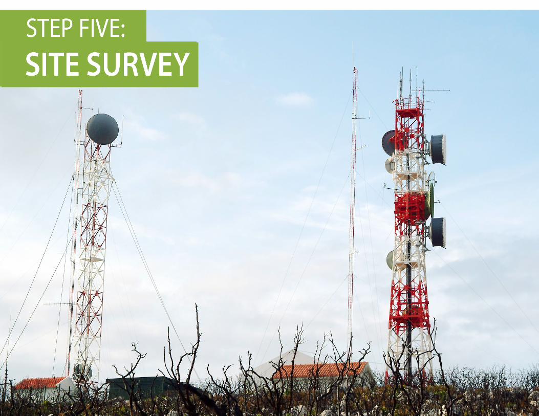
Site SurveyNeedless to say, for a successful deployment one of the most crucial steps is a detailed site survey. Site surveys include numerous activities, from inspection of the deployment area, to spectrum analysis gathering information about the available frequencies at the deployment site and finally the documentation and analysis of findings.
Site surveys come in many forms and can range from manual surveys wherein engineers step onto the site and perform a RF survey, to a completely hands-off “virtual” site survey using tools such as Google Earth, a link deployment application, or even a drone. All of these survey types have their own set of advantages and trade-offs in terms of time, cost, and precision analysis. The installer should determine which survey type best suits the complexity and attributes of the mounting location as well as the requirements of the project.

Wireless Network Design – Best Practices
© Proxim Wireless. All rights reserved.

Wireless Network Design – Best Practices
© Proxim Wireless. All rights reserved.
Omni Directional AntennaAs the name suggests, an omni directional antenna radiates RF energy somewhat uniformly in all directions (i.e. a beam width of 360°) and is used in outdoor environments where the signal can be located and pointed in any direction relative to the target or source. As an example, if a coverage area is an industrial site with a base station is located in one corner of the industrial yard, an omni-directional antenna could be a better choice for a service vehicle than sector or panel antenna. The Omni-directional antenna provides the service vehicle coverage throughout the industrial yard, providing a connection to the base station at any angle or vehicle orientation. Such coverage is likely not possible with antennas such as sector antennas because of the reduced radiation at different angles from the antenna.
Sector antennasAntennas propagating a signal with a beam-width of 30° to 120° with a narrow vertical width are often categorized as sector antennas. Sector antennas are typically used for installations where multiple base stations are used to provide coverage to a given region as opposed to a single base station with an Omni directional antenna. Using a properly beam width, a sector antenna can provide a wide coverage area with less influence from interference and noise from areas outside the coverage area. The proper beam width selection will also provide the proper signal strength within the coverage areas.
Antennas come in many form factors, but can be categorized into three basic types
Highly DirectionalHighly directional antennas typically have a beam width ranging from 100-300 such as parabolic or grid antennas. They are generally used for long-range (on the order of many miles) outdoor point-to-point connections or on subscriber units in point to multipoint deployments communicating back to the base station. Due to the high concentration of RF energy in a narrow beam width, engineers should ensure that the alignment between highly directional antennas is precise, any alignment error can lead to significant drop in network throughput.

Wireless Network Design – Best Practices
© Proxim Wireless. All rights reserved.

Wireless Network Design – Best Practices
© Proxim Wireless. All rights reserved.
Deployment Plan and ExecutionThe deployment should be executed in an orchestrated sequence of events which should take advantage of both parallel and serial events depending upon the size of the deployment team.
Items to be included in the Wireless Network Design Document• Network requirements for items such as bandwidth, security, and coverage areas• Target applications the network will support such as fixed and/or mobile endpoints • Requirement constraints such as technology limitations, mounting assets, and protocol support• Project constraints such as a budget and/or schedule
Items in the Deployment Report should include:• Spectral analysis for each mounting location at the time of deployment• RF parameters such as RSL, SNR, and calculated throughput for each radio location• Actual receive signal, SNR, and throughput at the time of deployment• Photo documentation of each radio at the mounting location
Bench TestBefore the link is sent out to the deployment site an operational test and some pre-deployment configuration should take place. This ensures some level of efficiency in the deployment process and often prevents troubleshooting in the field.
RF Condition and Spectrum AnalysisThe performance expectation for a link should be defined well before deployment, during the link planning phase. RF conditions are very dynamic so It is a Best Practice to perform a spectral analysis at the time of deployment. This analysis will either confirm the calculated throughput or provide some insight into the reasons a link might be underperforming when deployed. It is also a good documentation practice to include a Spectrum Analysis of each deployment location.
Alignment and Link OptimizationThe line of sight for the endpoints of the link should have been previously analyzed so the installer can align the link along a path of least obstruction. Radio link deployment environments can change so some real-time adjustment might be required to place the link on the best path. In this physical placement, some minor adjustment might be possible but it must be done with some caution. Placement of the radio can help with an obstructed path but can also be negatively affected by interference in a new location. Good alignment will always lead to a more successful deployment.
Documenting the Design and DeploymentDocumenting the design is critical for distribution to the project team stakeholders, identifying the requirements and constraints, and for use when issues arise both during deployment and post deployment. It is also critical to document the actual deployment for troubleshooting activities and if any of the project requirements are not met in the deployment.

Wireless Network Design – Best Practices
© Proxim Wireless. All rights reserved.
Conclusion:Wireless networking is challenging, from design to deployment, and each network has a unique set of requirements, target applications, and audience. To ensure network engineers and installers alike are able to overcome these challenges, a set of guidelines and best practices are in place which must be considered when deploying a wireless network. Ignoring or failing to follow a simple set of practices will be the difference between successful deployments which meet the expectations of the network audience and a failed deployment requiring many hours of troubleshooting for the network operators. For more information of network design Click here.
About ProximProxim Wireless Corporation (OTC Markets: PRXM) provides Wi-Fi®, Point-to-Point and Point-to-Multipoint 4G wireless network technologies for wireless
internet, video surveillance and backhaul applications. Our ORiNOCO® and Tsunami® product lines are sold to service providers, governments and
enterprises with over 2 million devices shipped to over 250,000 customers in over 90 countries worldwide. Proxim is ISO 9001-2008 certified.
For more information, visit www.proxim.com. For investor relations information, e-mail [email protected] or call +1 413-584-1425.


