Wireless Multi-Gigabit-Systems Workshop TU Braunschweig ...
28
Beam-forming antenna array configurations for 60-GHz broadband communication M. Imran Kazim Wireless Multi-Gigabit-Systems Workshop TU Braunschweig, Germany
Transcript of Wireless Multi-Gigabit-Systems Workshop TU Braunschweig ...

Beam-forming antenna array configurations for 60-GHz broadband communication
M. Imran Kazim
Wireless Multi-Gigabit-Systems WorkshopTU Braunschweig, Germany

PAGE 113-7-2009
Outline
• Introduction• Antenna element• Measurements• Antenna array• Packaging• 3D/Conformal antenna array

PAGE 213-7-2009
Introduction
• Broadband communication in the 60 GHz band• Unlicensed bandwidth of around 7 GHz• Data rates of multiple gigabits-per-second• Applications− wireless USB 2.0− wireless HDTV− wireless gigabit ethernet− telecom backhaul
• Low-cost integrated package− transceiver chip-set− antenna− other passive components

PAGE 313-7-2009
Antenna element- Geometry
• Balanced-fed aperture-coupledpatch antenna• realized in printed circuit-board• no vias• high radiation efficiency− >80%
• bandwidth− 10-15 %
balanced-fed aperture-coupled patch antenna
PCB stack

PAGE 413-7-2009
Antenna element- Modelling
• Modelling• Green's functions for stratified media• Method of moments− spectral-domain representation− basis functions− entire-domain− rooftop
− C++ implementation• Sensitivity analysis and optimization
PAGE 513-7-2009
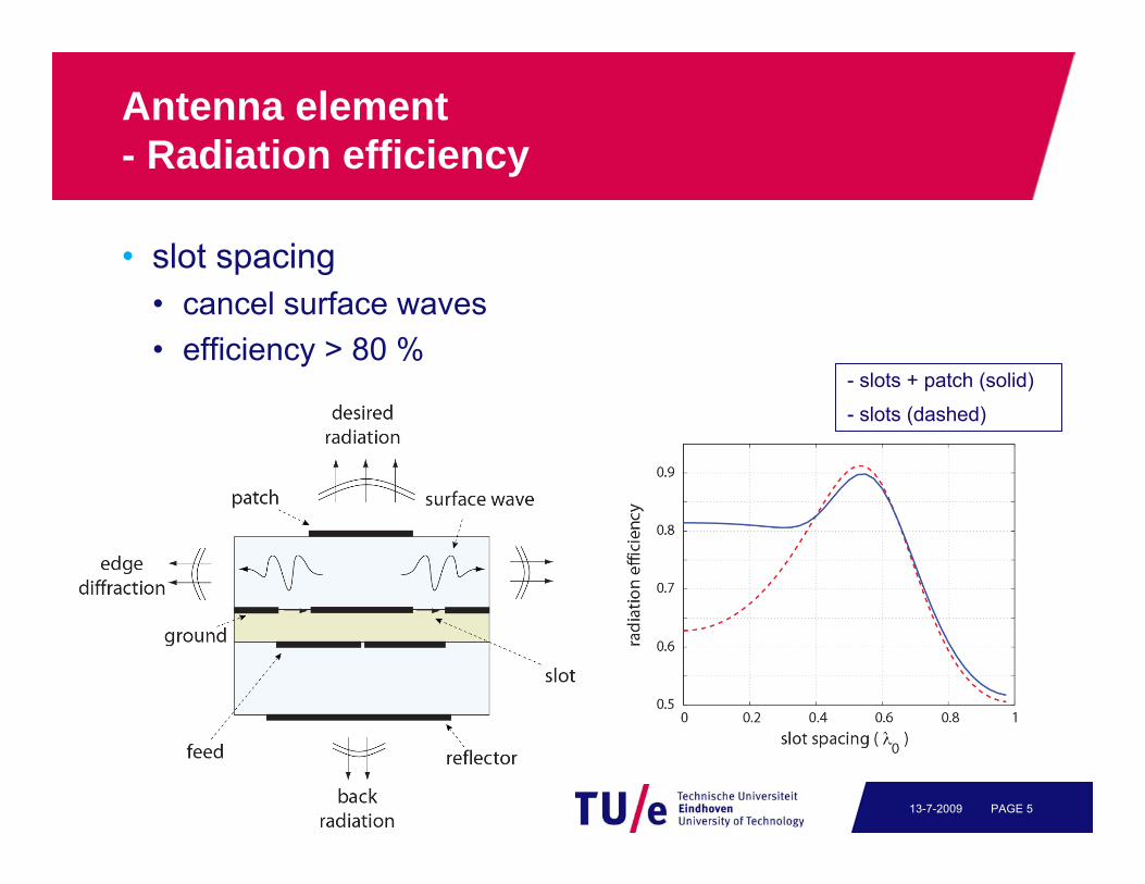
Antenna element- Radiation efficiency
• slot spacing• cancel surface waves• efficiency > 80 %
- slots + patch (solid)
- slots (dashed)

PAGE 613-7-2009
Antenna element- Back radiation
• reflector element• comparison− no reflector− infinite metal plane − finite metal reflector
- finite reflector (solid)
- no reflector (dash-dot)
- infinite reflector (dashed)
PAGE 713-7-2009
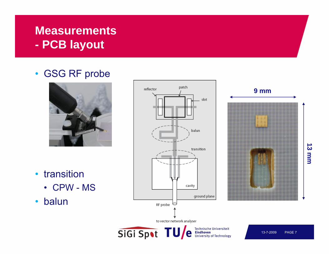
Measurements- PCB layout
• GSG RF probe
• transition• CPW - MS
• balun
9 mm
13 mm

PAGE 813-7-2009
Measurements- Radiation pattern
60 cm
• Far-field radiation pattern measurement• measures hemisphere• designed to reduce
unwanted scattering• features− RF probe support− open-ended waveguide− 0, 45, 90 degrees
− automated measurement− labview

PAGE 913-7-2009
Measurements- Radiation pattern

PAGE 1013-7-2009
Measurements- Time gating
• Measurementsin lab environment
• Time gating appliedgate: t = 1.8 - 4.9 ns

PAGE 1113-7-2009
Measurements- Results
• Measurement results
- measurements (solid)
- simulation [Spark] (dashed)
- measurements (solid)
- simulation [CST] (dashed)
- simulation [Spark] (dash-dot)

PAGE 1213-7-2009
Antenna array
• Beam-forming antenna array• 6-element circular array• feed network designed for
scan to θ = 0, 30, 45 degrees• problem:
large feed-line losses(1.3 dB/cm)
PAGE 1313-7-2009
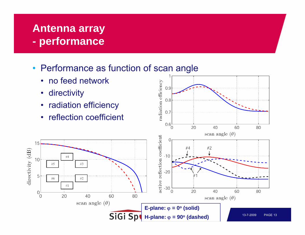
Antenna array- performance
• Performance as function of scan angle• no feed network• directivity• radiation efficiency• reflection coefficient
E-plane: ϕ = 0o (solid)H-plane: ϕ = 90o (dashed)

PAGE 1413-7-2009
Antenna array- Results
• Measurement results• beam-forming to 0, 30, 45 degrees
- simulation (dashed)
- measurement (solid)
broadside 30 degrees 45 degrees

PAGE 1513-7-2009
Packaging- PCB stack
• Teflon-based materials
• ceramic materials• vias

PAGE 1613-7-2009
Packaging- Material characterization
Microstrip Ring Resonator
PAGE 1713-7-2009
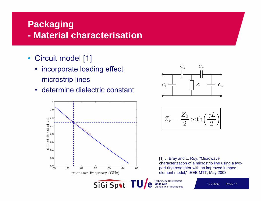
Packaging- Material characterisation
• Circuit model [1]• incorporate loading effect
microstrip lines• determine dielectric constant
[1] J. Bray and L. Roy, "Microwave characterization of a microstrip line using a two-port ring resonator with an improved lumped-element model," IEEE MTT, May 2003

PAGE 1813-7-2009
Packaging- Material characterisation
• RO4350B• data sheet (10 GHz)
εr = 3.66

PAGE 1913-7-2009
Packaging- Layout
• Single-element antenna
• CMOS power amplifier

PAGE 2013-7-2009
Packaging- Chip mount
• chip mount PA• flip-chip interconnection

PAGE 2113-7-2009
Packaging- Antenna performance
• Antenna measurement• balanced measurement• bandwidth− 57.7 - 65.1 GHz
50 55 60 65 70-30
-25
-20
-15
-10
-5
0
frequency (GHz)
S11
( dB
)

PAGE 2213-7-2009
Packaging- PA + antenna
• Probe station• MsM group

PAGE 2313-7-2009
Packaging- PA + antenna
gain measurement
- antenna (solid)
- PA + antenna (dashed)
- measurements (solid)
- simulation (dashed)
pattern measurement
• Flip-chip considerations− On-chip inductor− Extra plating layer on aluminium pads of the CMOS chip

PAGE 2413-7-2009
3D/Conformal antenna array
Passive Electromagnetic Deflector

PAGE 2513-7-2009
3D/Conformal antenna arrays
Flex PCB technology
Trade-off between directivity, steerability and size of the deflector

PAGE 2613-7-2009
Conclusions
• Antenna element• high efficiency, large bandwidth• MoM model− limited number of basis function
• Optimisation− simple, efficient method
• Measurement setup• RF probes− avoid interconnection problems
• radiation pattern setup

PAGE 2713-7-2009
Conclusions
• Antenna array• beam-forming demonstrated
• Packaging• integration with PA• flip-chip interconnect• realization of 7 GHz bandwidth (57.5 to 65.0 GHz) using the
packaged PA-antenna • 3D/Conformal antenna arrays
Almost there...