
Wireless Fidelity (WiFi)alfuqaha/Fall09/cs6030/lectures/...WiFi, WiMAX Wireless Fidelity (WiFi) IEEE...
39
Wireless Local and Metropolitan Area Networks (WLAN, WMAN) WiFi, WiMAX Wireless Fidelity (WiFi)
Transcript of Wireless Fidelity (WiFi)alfuqaha/Fall09/cs6030/lectures/...WiFi, WiMAX Wireless Fidelity (WiFi) IEEE...
Wireless Local and Metropolitan Area Networks (WLAN, WMAN)
WiFi, WiMAX
Wireless Fidelity (WiFi)
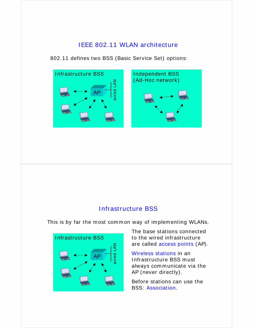
IEEE 802.11 WLAN architecture
802.11 defines two BSS (Basic Service Set) options:
Infrastructure BSS Independent BSS(Ad-Hoc network)
AP
wired
LAN
Infrastructure BSS
This is by far the most common way of implementing WLANs.
Infrastructure BSS
AP
The base stations connected to the wired infrastructure are called access points (AP).
Wireless stations in an Infrastructure BSS must always communicate via the AP (never directly).
Before stations can use the BSS: Association.
wired
LAN
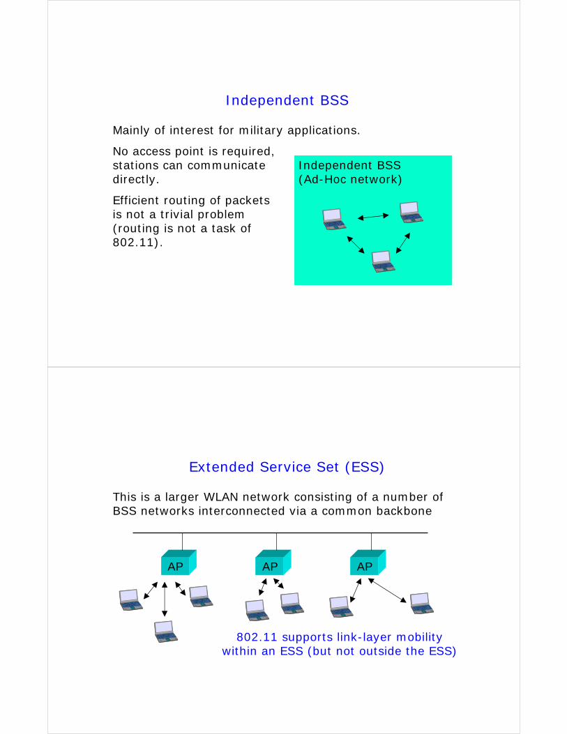
Independent BSS
Mainly of interest for military applications.
Independent BSS(Ad-Hoc network)
No access point is required, stations can communicate directly.
Efficient routing of packets is not a trivial problem(routing is not a task of 802.11).
Extended Service Set (ESS)
This is a larger WLAN network consisting of a number of BSS networks interconnected via a common backbone
AP AP AP
802.11 supports link-layer mobility within an ESS (but not outside the ESS)
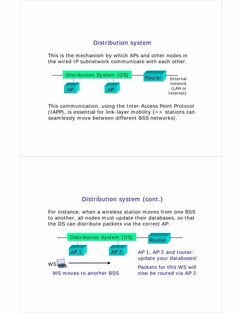
Distribution system
This is the mechanism by which APs and other nodes in the wired IP subnetwork communicate with each other.
AP AP
RouterDistribution System (DS)
This communication, using the Inter-Access Point Protocol (IAPP), is essential for link-layer mobility (=> stations can seamlessly move between different BSS networks).
External network (LAN or
Internet)
Distribution system (cont.)
For instance, when a wireless station moves from one BSS to another, all nodes must update their databases, so that the DS can distribute packets via the correct AP.
AP 1 AP 2
Router
WS
AP 1, AP 2 and router: update your databases!
Packets for this WS will now be routed via AP 2.
Distribution System (DS)
WS moves to another BSS
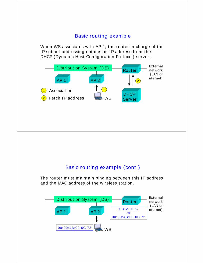
Basic routing example
When WS associates with AP 2, the router in charge of the IP subnet addressing obtains an IP address from the DHCP (Dynamic Host Configuration Protocol) server.
Router
AP 1 AP 2
Distribution System (DS)
DHCP Server
Association
Fetch IP address
1
2
1
2
External network (LAN or
Internet)
WS
Basic routing example (cont.)
The router must maintain binding between this IP address and the MAC address of the wireless station.
Router
AP 1 AP 2
Distribution System (DS) External network (LAN or
Internet)124.2.10.57
00:90:4B:00:0C:72
00:90:4B:00:0C:72 WS
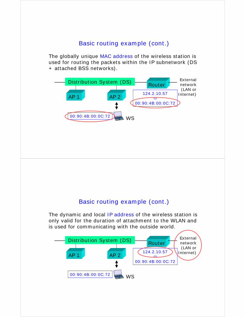
Basic routing example (cont.)
The globally unique MAC address of the wireless station is used for routing the packets within the IP subnetwork (DS + attached BSS networks).
Router
AP 1 AP 2
Distribution System (DS) External network (LAN or
Internet)124.2.10.57
00:90:4B:00:0C:72
00:90:4B:00:0C:72 WS
Basic routing example (cont.)
The dynamic and local IP address of the wireless station is only valid for the duration of attachment to the WLAN and is used for communicating with the outside world.
Router
AP 1 AP 2
Distribution System (DS) External network (LAN or
Internet)124.2.10.57
00:90:4B:00:0C:72
00:90:4B:00:0C:72 WS
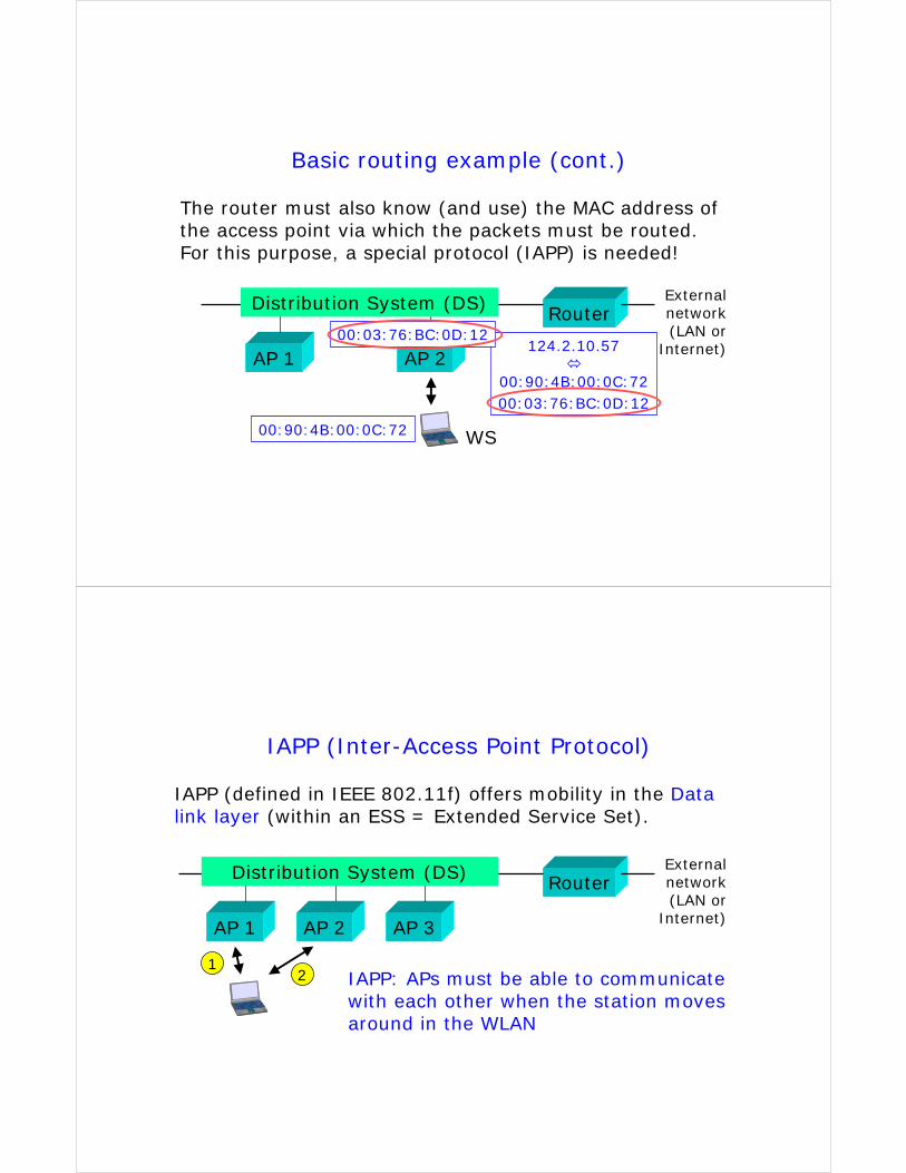
Basic routing example (cont.)
The router must also know (and use) the MAC address of the access point via which the packets must be routed. For this purpose, a special protocol (IAPP) is needed!
Router
AP 1 AP 2
Distribution System (DS) External network (LAN or
Internet)124.2.10.57
00:90:4B:00:0C:7200:03:76:BC:0D:12
00:90:4B:00:0C:72
00:03:76:BC:0D:12
WS
IAPP (Inter-Access Point Protocol)
IAPP (defined in IEEE 802.11f) offers mobility in the Data link layer (within an ESS = Extended Service Set).
Router
AP 1 AP 3
Distribution System (DS) External network (LAN or
Internet)AP 2
IAPP: APs must be able to communicate with each other when the station moves around in the WLAN
12
In addition to IAPP …
IAPP alone is not sufficient to enable seamless handovers in a WLAN. The stations must be able to measure the signal strengths from surrounding APs and decide when and to which AP a handover should be performed (no 802.11 standardised solutions are available for this operation).
In 802.11 networks, a handover means reassociating with the new AP.
Mobility Management (MM)
There are basically two objectives of Mobility Management:
MM offers seamless handovers when moving from one network/subnetwork/BSS to another
MM makes sure that users or terminals can be reached when they move to another network/subnetwork/BSS
1.
2.
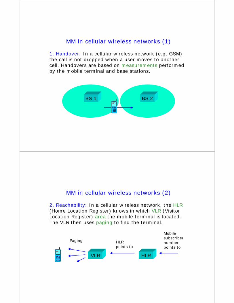
MM in cellular wireless networks (1)
1. Handover: In a cellular wireless network (e.g. GSM), the call is not dropped when a user moves to another cell. Handovers are based on measurements performed by the mobile terminal and base stations.
BS 1 BS 2
MM in cellular wireless networks (2)
VLR HLR
2. Reachability: In a cellular wireless network, the HLR(Home Location Register) knows in which VLR (Visitor Location Register) area the mobile terminal is located. The VLR then uses paging to find the terminal.
Mobile subscriber number points to
HLR points to
Paging
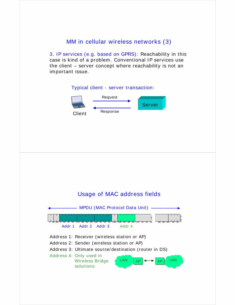
MM in cellular wireless networks (3)
3. IP services (e.g. based on GPRS): Reachability in this case is kind of a problem. Conventional IP services use the client – server concept where reachability is not an important issue.
Server
Client
Request
Response
Typical client - server transaction:
Usage of MAC address fields
MPDU (MAC Protocol Data Unit)
Addr 1 Addr 2 Addr 3 Addr 4
Address 1: Receiver (wireless station or AP)Address 2: Sender (wireless station or AP)Address 3: Ultimate source/destination (router in DS)Address 4: Only used in
Wireless Bridge solutions:
LANLAN LANLANAPAP APAP
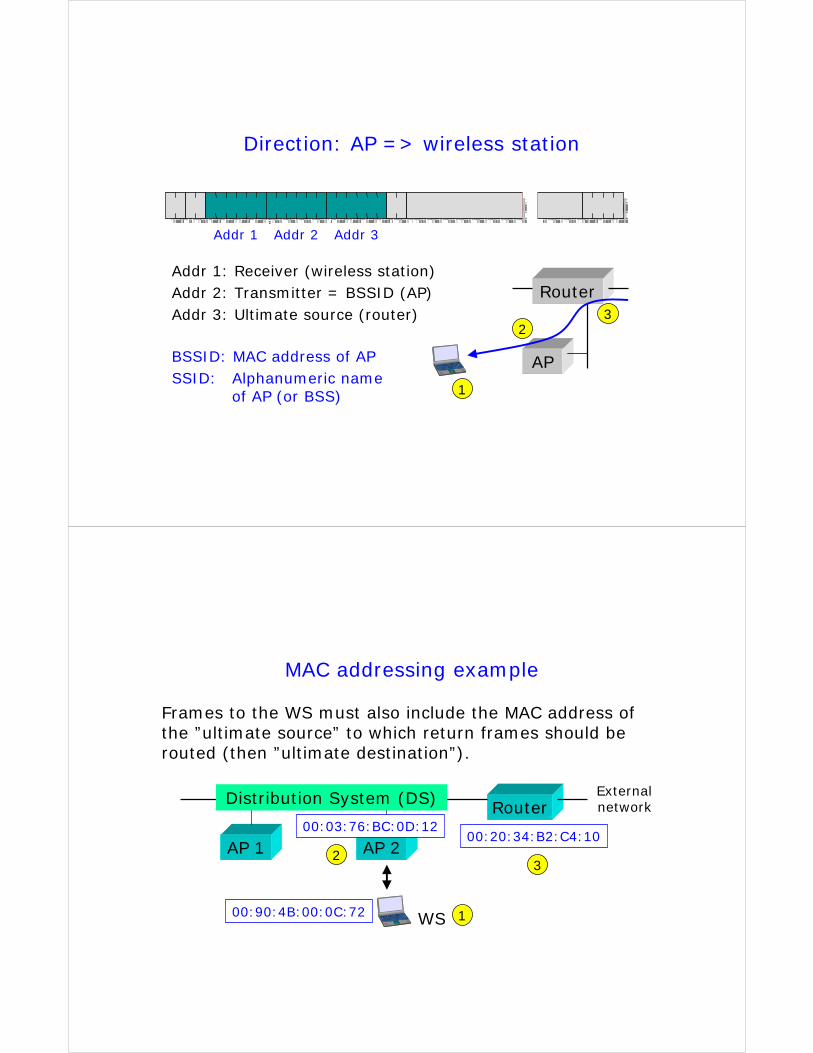
Direction: AP => wireless station
Addr 1 Addr 2 Addr 3
Addr 1: Receiver (wireless station)Addr 2: Transmitter = BSSID (AP)Addr 3: Ultimate source (router)
AP
Router
BSSID: MAC address of APSSID: Alphanumeric name
of AP (or BSS) 1
23
MAC addressing example
Frames to the WS must also include the MAC address of the ”ultimate source” to which return frames should be routed (then ”ultimate destination”).
Router
AP 1 AP 2
Distribution System (DS) External network
00:20:34:B2:C4:10
00:90:4B:00:0C:72
00:03:76:BC:0D:12
WS 1
23
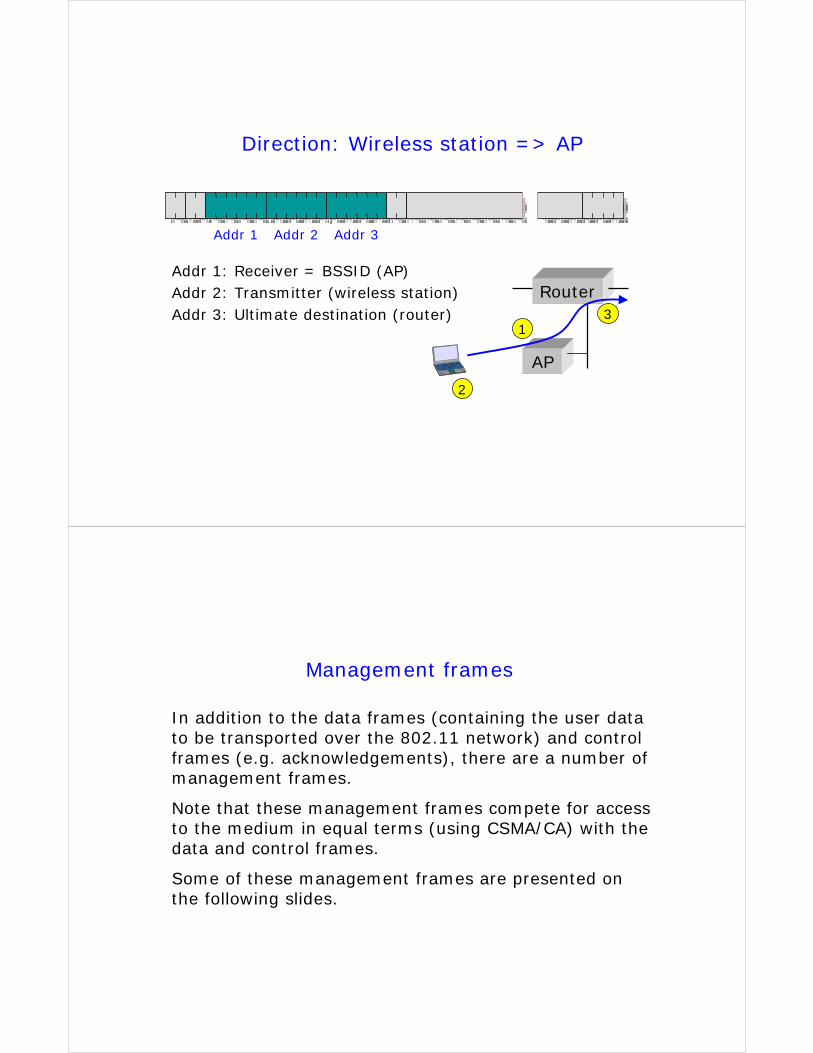
Direction: Wireless station => AP
Addr 1 Addr 2 Addr 3
Addr 1: Receiver = BSSID (AP)Addr 2: Transmitter (wireless station)Addr 3: Ultimate destination (router)
AP
Router
2
13
Management frames
In addition to the data frames (containing the user data to be transported over the 802.11 network) and control frames (e.g. acknowledgements), there are a number of management frames.
Note that these management frames compete for access to the medium in equal terms (using CSMA/CA) with the data and control frames.
Some of these management frames are presented on the following slides.
Beacon frames
Beacon frames are broadcast (meaning that all stations shall receive them and read the information) at regular intervals from the Access Point. These frames contain (among others) the following information:
Timestamp (8 bytes) is necessary, so that stations can synchronise to the network
Beacon interval (2 bytes) in milliseconds
Capability info (2 bytes) advertises network capabilities
SSID (0 ... 32 bytes), alphanumeric “network name”
The channel number used by the network (optional).
Probe request & response frames
A probe request frame is transmitted from a wireless station during active scanning. Access points within reach respond by sending probe response frames.
Probe request frames contain the following information:SSID (0 ... 32 bytes), alphanumeric “network name”
Bit rates supported by the station. This is used by APs to see if the station can be permitted to join the network.
Probe response frames actually contain the same kind of “network information” as beacon frames.
Association request & response frames
Before a station can join an 802.11 network, it must send an association request frame. The AP responds with an association response frame.
Association request frames contain (among others):SSID, capability info, bit rates supported.
Association response frames contain (among others):Capability info, bit rates supported
Status code (success or failure with failure cause)
Association ID (used for various purposes)
Passive and active scanning
Wireless stations can find out about 802.11 networks by using passive or active scanning.
During passive scanning, the station searches beacon frames, moving from channel to channel through the complete channel set (802.11b => 13 channels).
During active scanning, the station selects Channel 1 and sends a probe request frame. If no probe response frame is received within a certain time, the station moves to Channel 2 and sends a probe request frame, and so on.
Case study 1: Station connecting to a WLAN
When a station moves into the coverage area of a WLAN, the following procedures take place:
1) Scanning: the station searches for a suitable channel over which subsequent communication takes place
2)
3)
4)
Association: the station associates with an AP
IP address allocation: the station gets an IP address, for instance from a DHCP server
Authentication: only if this security option is required.
Case study 2: Handover to another AP
When a station has noticed that the radio connection to another AP is a better than the existing connection:
1) Reassociation: the station associates with another AP
2) No new IP address is needed; however, the WLAN must be able to route downlink traffic via the new AP
3) Authentication: this security option, if required, will result in a substantially increased handover delay (complete procedure sequence: deauthentication, disassociation, reassociation, authentication).
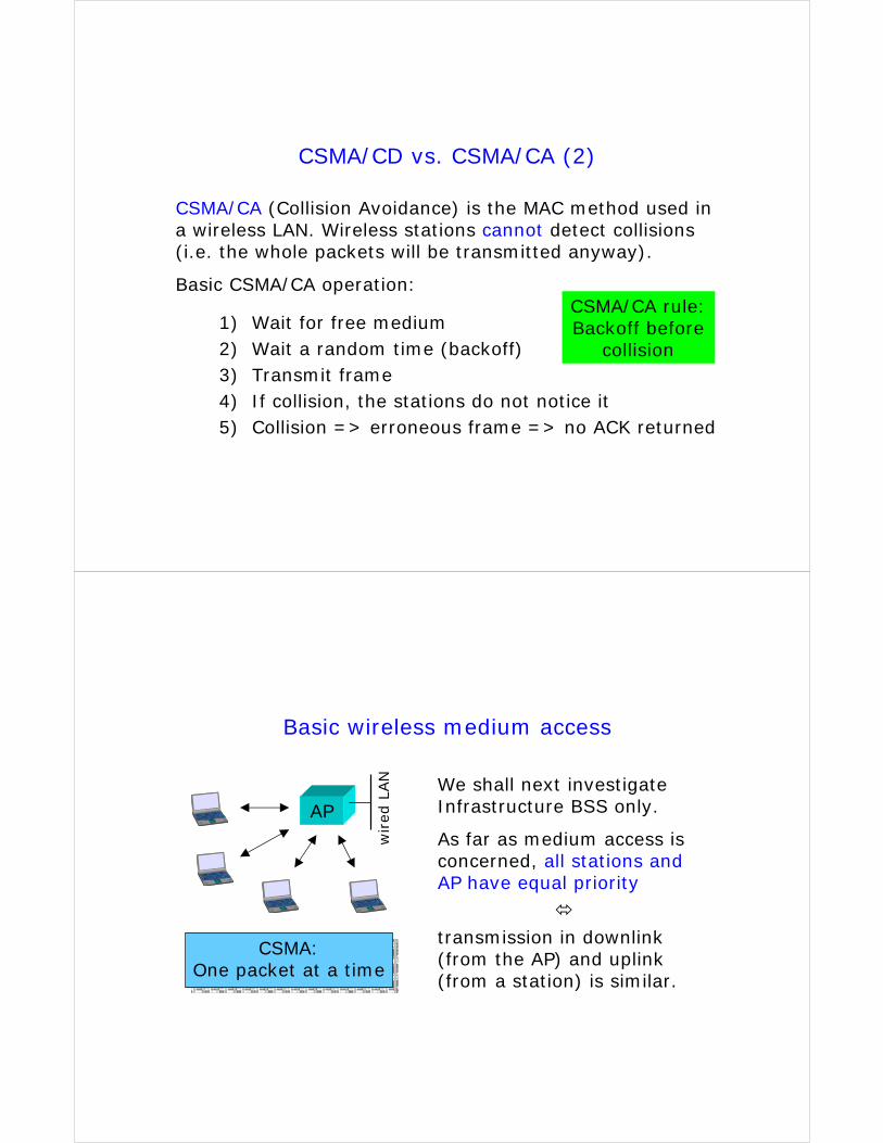
CSMA/CD vs. CSMA/CA (2)
CSMA/CA (Collision Avoidance) is the MAC method used in a wireless LAN. Wireless stations cannot detect collisions(i.e. the whole packets will be transmitted anyway).
Basic CSMA/CA operation:
1) Wait for free medium 2) Wait a random time (backoff)3) Transmit frame4) If collision, the stations do not notice it5) Collision => erroneous frame => no ACK returned
CSMA/CA rule: Backoff before
collision
Basic wireless medium access
APWe shall next investigateInfrastructure BSS only.
As far as medium access is concerned, all stations and AP have equal priority
transmission in downlink(from the AP) and uplink(from a station) is similar.
CSMA:One packet at a time
wired
LAN

DCF (CSMA/CA) vs. PCF
Distributed Coordination Function (DCF) based on CSMA/CA
Point Coordination Function (PCF)
MAC extent
Used for contention services (and basis for PCF)
Designed for contention-free services (delay-sensitive real-time services such as voice transmission), but has not been implemented (yet)
Wireless medium access (1)
DIFS SIFS
ACK (B=>A)
Transmittedframe
(A=>B)
When a frame is received without bit errors, the receivingstation (B) sends an Acknowledgement (ACK) frame backto the transmitting station (A).
If the received frameis erroneous, no ACK will be sent
Cyclic RedundancyCheck (CRC) is usedfor error detection

Wireless medium access (2)
DIFS SIFS DIFS
ACK (B=>A)
Transmittedframe
(A=>B)
During the transmission sequence (Frame + SIFS + ACK) the medium (radio channel) is reserved. The next framecan be transmitted at earliest after the next DIFS period.
Next frame(from any station)
Earliest allowedtransmission timeof next frame
Wireless medium access (3)
DIFS SIFS DIFS
ACK (B=>A)
Transmittedframe
(A=>B)
There are two mechanisms for reserving the channel: Physical carrier sensing and Virtual carrier sensing usingthe so-called Network Allocation Vector (NAV).
Next frame
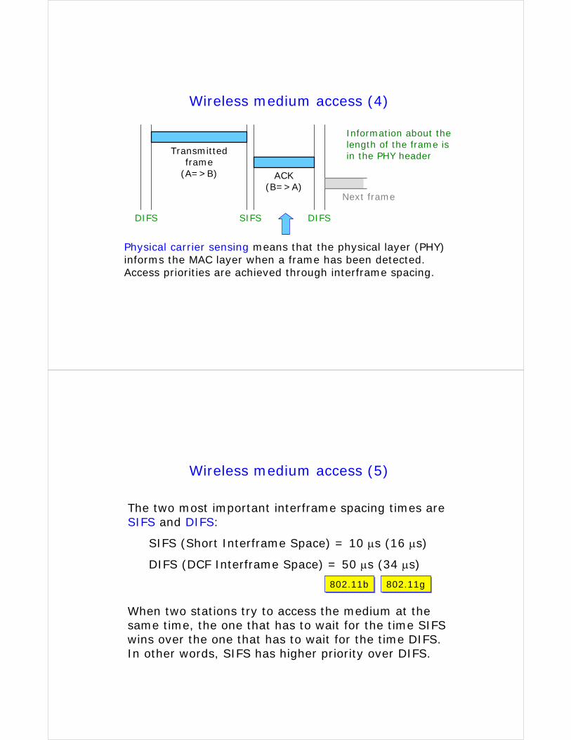
Wireless medium access (4)
DIFS SIFS DIFS
ACK (B=>A)
Transmittedframe
(A=>B)
Physical carrier sensing means that the physical layer (PHY) informs the MAC layer when a frame has been detected. Access priorities are achieved through interframe spacing.
Next frame
Information about the length of the frame is in the PHY header
Wireless medium access (5)
The two most important interframe spacing times areSIFS and DIFS:
SIFS (Short Interframe Space) = 10 µs (16 µs)
DIFS (DCF Interframe Space) = 50 µs (34 µs)
When two stations try to access the medium at the same time, the one that has to wait for the time SIFS wins over the one that has to wait for the time DIFS. In other words, SIFS has higher priority over DIFS.
802.11b802.11b 802.11g802.11g
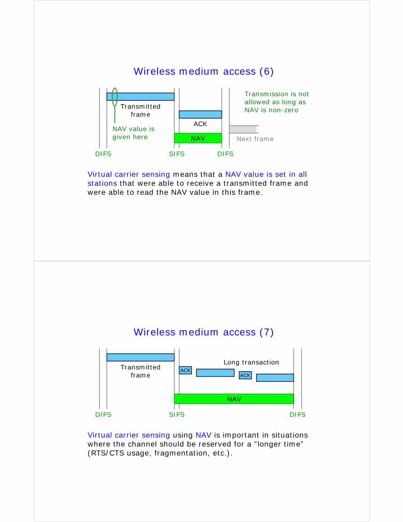
Wireless medium access (6)
DIFS SIFS DIFS
ACK
Transmittedframe
NAV
Virtual carrier sensing means that a NAV value is set in allstations that were able to receive a transmitted frame and were able to read the NAV value in this frame.
NAV value is given here Next frame
Transmission is notallowed as long as NAV is non-zero
Wireless medium access (7)
DIFS SIFS
Transmittedframe
NAV
Virtual carrier sensing using NAV is important in situationswhere the channel should be reserved for a ”longer time”(RTS/CTS usage, fragmentation, etc.).
ACKACK
Long transaction
DIFS
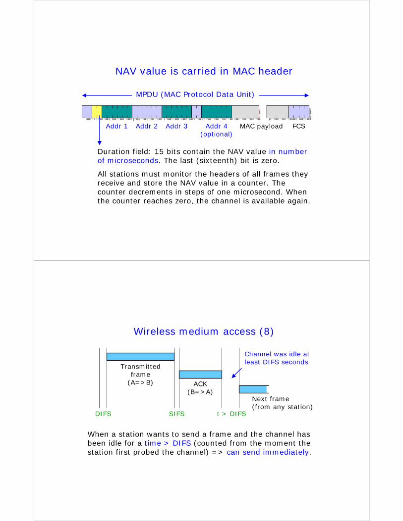
NAV value is carried in MAC header
MPDU (MAC Protocol Data Unit)
MAC payloadAddr 1 Addr 2 Addr 3 Addr 4 (optional)
FCS
Duration field: 15 bits contain the NAV value in number of microseconds. The last (sixteenth) bit is zero.
All stations must monitor the headers of all frames they receive and store the NAV value in a counter. The counter decrements in steps of one microsecond. When the counter reaches zero, the channel is available again.
Wireless medium access (8)
DIFS SIFS t > DIFS
ACK (B=>A)
Transmittedframe
(A=>B)
When a station wants to send a frame and the channel hasbeen idle for a time > DIFS (counted from the moment the station first probed the channel) => can send immediately.
Next frame(from any station)
Channel was idle at least DIFS seconds
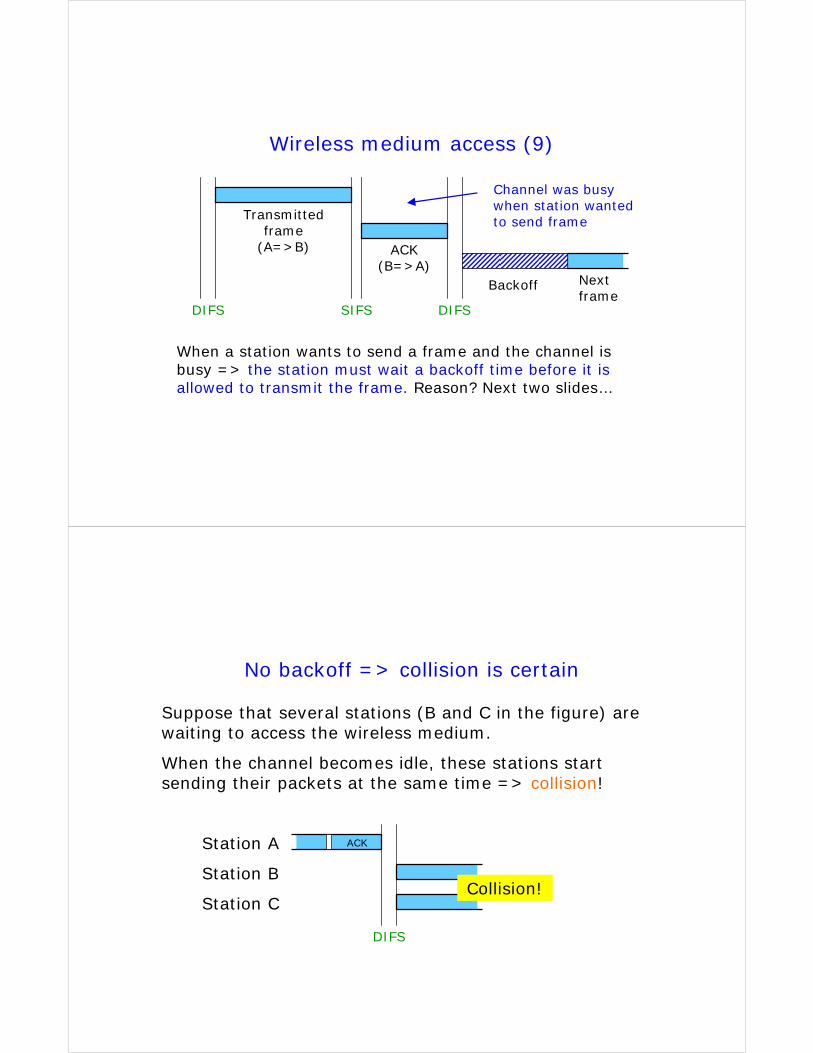
Wireless medium access (9)
DIFS SIFS DIFS
ACK (B=>A)
Transmittedframe
(A=>B)
When a station wants to send a frame and the channel is busy => the station must wait a backoff time before it is allowed to transmit the frame. Reason? Next two slides…
Nextframe
Channel was busywhen station wantedto send frame
Backoff
No backoff => collision is certain
Suppose that several stations (B and C in the figure) arewaiting to access the wireless medium.
When the channel becomes idle, these stations startsending their packets at the same time => collision!
Station A
Station B
Station C
DIFS
Collision!
ACK
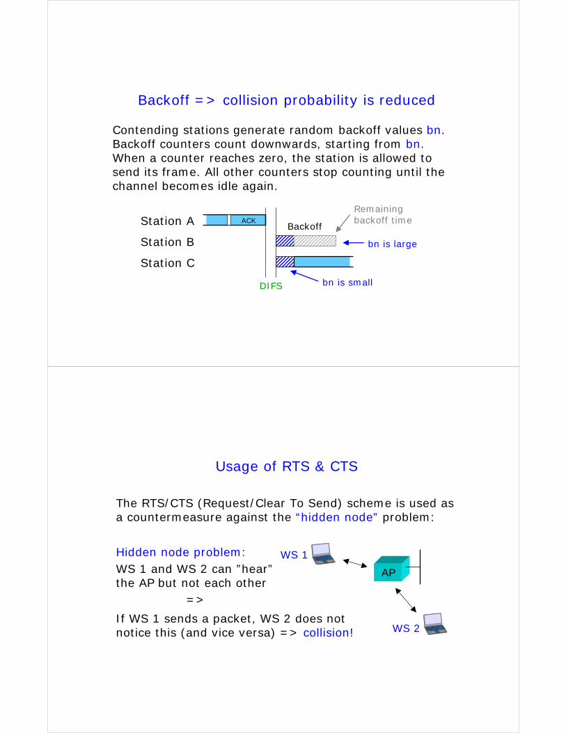
Backoff => collision probability is reduced
Contending stations generate random backoff values bn. Backoff counters count downwards, starting from bn. When a counter reaches zero, the station is allowed to send its frame. All other counters stop counting until the channel becomes idle again.
Station A
Station B
Station C
DIFS
bn is large
bn is small
Backoff
Remainingbackoff timeACK
Usage of RTS & CTS
The RTS/CTS (Request/Clear To Send) scheme is used as a countermeasure against the “hidden node” problem:
AP
WS 1
WS 2
Hidden node problem:WS 1 and WS 2 can ”hear”the AP but not each other
=>
If WS 1 sends a packet, WS 2 does not notice this (and vice versa) => collision!
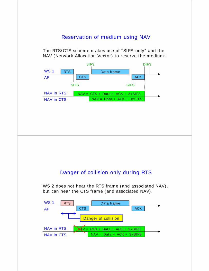
Reservation of medium using NAV
The RTS/CTS scheme makes use of “SIFS-only” and the NAV (Network Allocation Vector) to reserve the medium:
RTS
SIFS
DIFS
NAV = CTS + Data + ACK + 3xSIFS
CTSData frame
ACK
SIFS
SIFS
WS 1
AP
NAV = Data + ACK + 3xSIFS
NAV in RTS
NAV in CTS
Danger of collision only during RTS
WS 2 does not hear the RTS frame (and associated NAV), but can hear the CTS frame (and associated NAV).
RTS
NAV = CTS + Data + ACK + 3xSIFS
CTSData frame
ACK
WS 1
AP
NAV = Data + ACK + 3xSIFS
NAV in RTS
NAV in CTS
Danger of collision
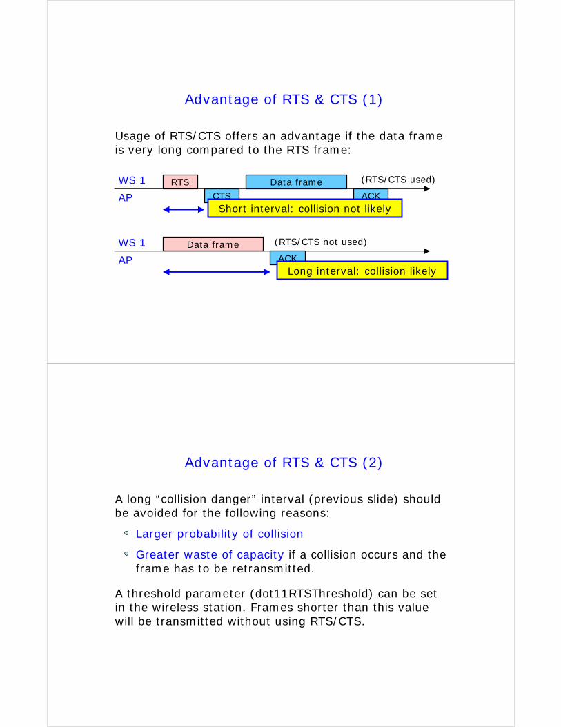
Advantage of RTS & CTS (1)
Usage of RTS/CTS offers an advantage if the data frame is very long compared to the RTS frame:
RTSCTS
Data frameACK
WS 1
APShort interval: collision not likely
Data frameACK
WS 1
APLong interval: collision likely
(RTS/CTS not used)
(RTS/CTS used)
Advantage of RTS & CTS (2)
A long “collision danger” interval (previous slide) should be avoided for the following reasons:
Larger probability of collision
Greater waste of capacity if a collision occurs and the frame has to be retransmitted.
A threshold parameter (dot11RTSThreshold) can be set in the wireless station. Frames shorter than this value will be transmitted without using RTS/CTS.
Worldwide Interoperability for Microwave Access (WiMAX)
IEEE 802.16
The standard IEEE 802.16 defines the air interface, including the MAC layer and multiple PHY layer options, for fixedBroadband Wireless Access (BWA) systems to be used in a Wireless Metropolitan Area Network (WMAN) for residential and enterprise use. IEEE 802.16 is also often referred to as WiMax. The WiMax Forum strives to ensure interoperability between different 802.16 implementations - a difficult task due to the large number of options in the standard.
IEEE 802.16 cannot be used in a mobile environment. For this purpose, IEEE 802.16e is being developed. This standard will compete with the IEEE 802.20 standard (still in early phase).
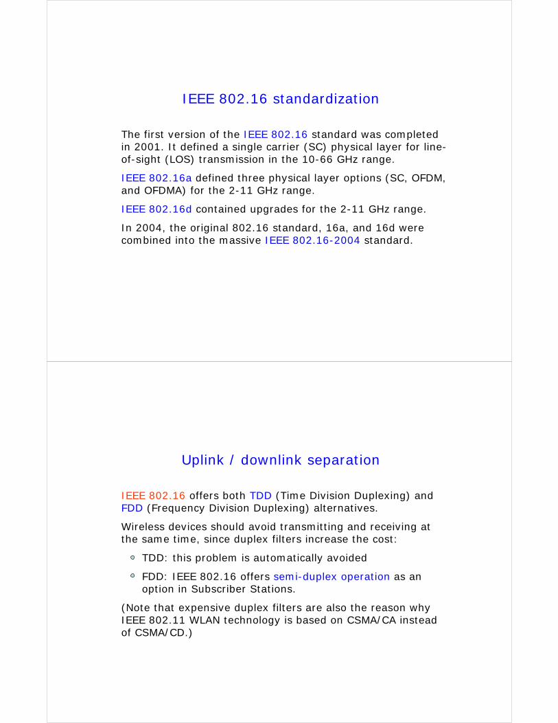
IEEE 802.16 standardization
The first version of the IEEE 802.16 standard was completed in 2001. It defined a single carrier (SC) physical layer for line-of-sight (LOS) transmission in the 10-66 GHz range.
IEEE 802.16a defined three physical layer options (SC, OFDM, and OFDMA) for the 2-11 GHz range.
IEEE 802.16d contained upgrades for the 2-11 GHz range.
In 2004, the original 802.16 standard, 16a, and 16d were combined into the massive IEEE 802.16-2004 standard.
Uplink / downlink separation
IEEE 802.16 offers both TDD (Time Division Duplexing) and FDD (Frequency Division Duplexing) alternatives.
Wireless devices should avoid transmitting and receiving at the same time, since duplex filters increase the cost:
TDD: this problem is automatically avoided
FDD: IEEE 802.16 offers semi-duplex operation as an option in Subscriber Stations.
(Note that expensive duplex filters are also the reason why IEEE 802.11 WLAN technology is based on CSMA/CA instead of CSMA/CD.)
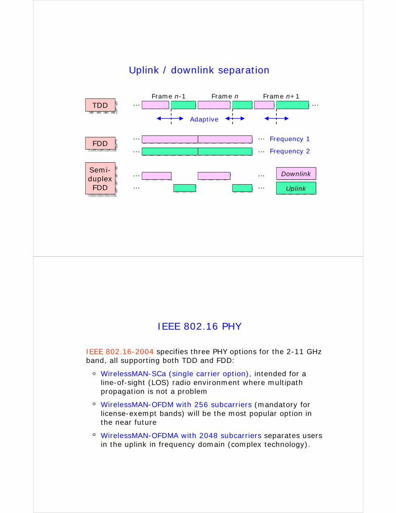
Uplink / downlink separation
TDDTDD
FDDFDD
Semi-duplexFDD
Semi-duplexFDD
DownlinkDownlink
UplinkUplink
… …
Adaptive
Frequency 1
Frequency 2
…
…
…
…
…
…
…
…
Frame n-1 Frame n Frame n+1
IEEE 802.16 PHY
IEEE 802.16-2004 specifies three PHY options for the 2-11 GHz band, all supporting both TDD and FDD:
WirelessMAN-SCa (single carrier option), intended for a line-of-sight (LOS) radio environment where multipathpropagation is not a problem
WirelessMAN-OFDM with 256 subcarriers (mandatory for license-exempt bands) will be the most popular option in the near future
WirelessMAN-OFDMA with 2048 subcarriers separates users in the uplink in frequency domain (complex technology).
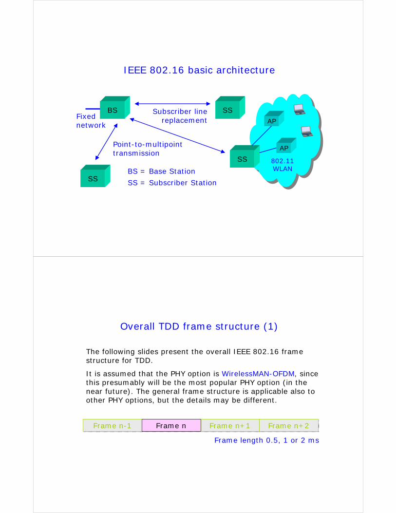
IEEE 802.16 basic architecture
BS SS
SS
SS
Point-to-multipoint transmission
AP
AP
802.11 WLANBS = Base Station
SS = Subscriber Station
Fixed network
Subscriber line replacement
Overall TDD frame structure (1)
Frame n-1Frame n-1 Frame nFrame n Frame n+1Frame n+1 Frame n+2Frame n+2
Frame length 0.5, 1 or 2 ms
The following slides present the overall IEEE 802.16 frame structure for TDD.
It is assumed that the PHY option is WirelessMAN-OFDM, since this presumably will be the most popular PHY option (in the near future). The general frame structure is applicable also to other PHY options, but the details may be different.

Overall TDD frame structure (2)
Frame n-1Frame n-1 Frame nFrame n Frame n+1Frame n+1 Frame n+2Frame n+2
DL PHYPDU
DL PHYPDU
Contentionslot A
Contentionslot A
Contentionslot B
Contentionslot B
UL PHYburst 1UL PHYburst 1
UL PHYburst kUL PHYburst k
…
DL subframe UL subframe
TDMA bursts from different subscriber stations (each with its own preamble)
TDM signal in downlink
For initial ranging
For BW requests
Adaptive
UL PHYburst kUL PHYburst k
DL subframe structure (1)
DL PHYPDU
DL PHYPDU
Contentionslot A
Contentionslot A
Contentionslot B
Contentionslot B
UL PHYburst 1UL PHYburst 1
…
PreamblePreamble FCHFCH DL burst 1DL burst 1 DL burst nDL burst n…
…
The DL subframe starts with a preamble (necessary for frame synchronization and equalization) and the Frame Control Header (FCH) that contains the location and burst profile of the first DL burst following the FCH. The FCH is one OFDM symbol long and is transmitted using BPSK modulation.
UL PHYburst kUL PHYburst k
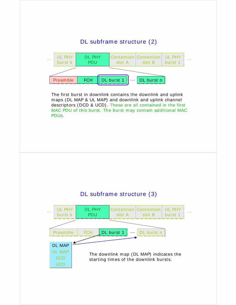
DL subframe structure (2)
DL PHYPDU
DL PHYPDU
Contentionslot A
Contentionslot A
Contentionslot B
Contentionslot B
UL PHYburst 1UL PHYburst 1
…
PreamblePreamble FCHFCH DL burst 1DL burst 1 DL burst nDL burst n…
…
The first burst in downlink contains the downlink and uplink maps (DL MAP & UL MAP) and downlink and uplink channel descriptors (DCD & UCD). These are all contained in the first MAC PDU of this burst. The burst may contain additional MAC PDUs.
UL PHYburst kUL PHYburst k
DL subframe structure (3)
DL PHYPDU
DL PHYPDU
Contentionslot A
Contentionslot A
Contentionslot B
Contentionslot B
UL PHYburst 1UL PHYburst 1
…
PreamblePreamble FCHFCH DL burst 1DL burst 1 DL burst nDL burst n…
…
DL MAPUL MAP
DCDUCD
DL MAPUL MAP
DCDUCD
The downlink map (DL MAP) indicates the starting times of the downlink bursts.
UL PHYburst kUL PHYburst k
DL subframe structure (4)
DL PHYPDU
DL PHYPDU
Contentionslot A
Contentionslot A
Contentionslot B
Contentionslot B
UL PHYburst 1UL PHYburst 1
…
PreamblePreamble FCHFCH DL burst 1DL burst 1 DL burst nDL burst n…
…
DL MAPUL MAP
DCDUCD
DL MAPUL MAP
DCDUCD
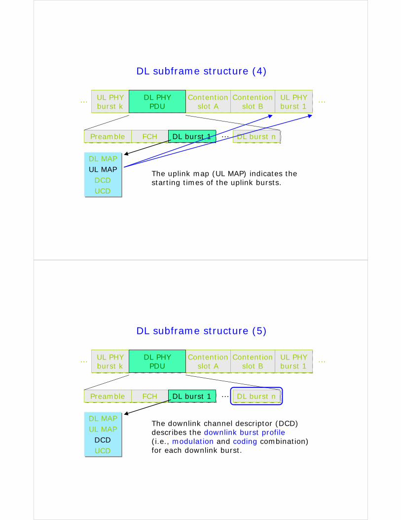
The uplink map (UL MAP) indicates the starting times of the uplink bursts.
UL PHYburst kUL PHYburst k
DL subframe structure (5)
DL PHYPDU
DL PHYPDU
Contentionslot A
Contentionslot A
Contentionslot B
Contentionslot B
UL PHYburst 1UL PHYburst 1
…
PreamblePreamble FCHFCH DL burst 1DL burst 1 DL burst nDL burst n…
…
DL MAPUL MAP
DCDUCD
DL MAPUL MAP
DCDUCD
The downlink channel descriptor (DCD) describes the downlink burst profile(i.e., modulation and coding combination) for each downlink burst.
UL PHYburst kUL PHYburst k
DL subframe structure (6)
DL PHYPDU
DL PHYPDU
Contentionslot A
Contentionslot A
Contentionslot B
Contentionslot B
UL PHYburst 1UL PHYburst 1
…
PreamblePreamble FCHFCH DL burst 1DL burst 1 DL burst nDL burst n…
…
DL MAPUL MAP
DCDUCD
DL MAPUL MAP
DCDUCD
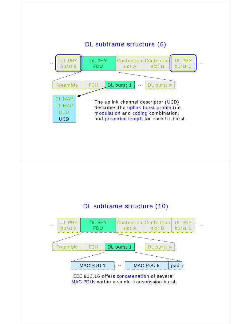
The uplink channel descriptor (UCD) describes the uplink burst profile (i.e., modulation and coding combination) and preamble length for each UL burst.
UL PHYburst kUL PHYburst k
DL subframe structure (10)
DL PHYPDU
DL PHYPDU
Contentionslot A
Contentionslot A
Contentionslot B
Contentionslot B
UL PHYburst 1UL PHYburst 1
…
PreamblePreamble FCHFCH DL burst 1DL burst 1 DL burst nDL burst n…
…
MAC PDU 1MAC PDU 1 … MAC PDU kMAC PDU k padpad
IEEE 802.16 offers concatenation of several MAC PDUs within a single transmission burst.
UL PHYburst kUL PHYburst k
UL subframe structure (1)
DL PHYPDU
DL PHYPDU
Contentionslot A
Contentionslot A
Contentionslot B
Contentionslot B
UL PHYburst 1UL PHYburst 1
…
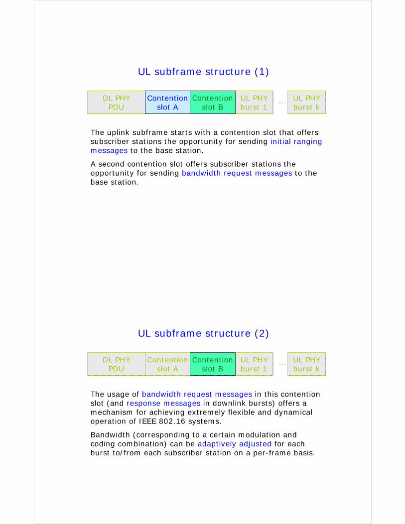
The uplink subframe starts with a contention slot that offers subscriber stations the opportunity for sending initial ranging messages to the base station.
A second contention slot offers subscriber stations the opportunity for sending bandwidth request messages to the base station.
UL PHYburst kUL PHYburst k
UL subframe structure (2)
DL PHYPDU
DL PHYPDU
Contentionslot A
Contentionslot A
Contentionslot B
Contentionslot B
UL PHYburst 1UL PHYburst 1
…
The usage of bandwidth request messages in this contention slot (and response messages in downlink bursts) offers a mechanism for achieving extremely flexible and dynamical operation of IEEE 802.16 systems.
Bandwidth (corresponding to a certain modulation and coding combination) can be adaptively adjusted for each burst to/from each subscriber station on a per-frame basis.
Four service classes
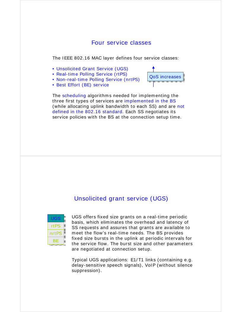
The IEEE 802.16 MAC layer defines four service classes:
• Unsolicited Grant Service (UGS)• Real-time Polling Service (rtPS)• Non-real-time Polling Service (nrtPS)• Best Effort (BE) service
The scheduling algorithms needed for implementing the three first types of services are implemented in the BS(while allocating uplink bandwidth to each SS) and are not defined in the 802.16 standard. Each SS negotiates its service policies with the BS at the connection setup time.
QoS increasesQoS increases
Unsolicited grant service (UGS)
UGS offers fixed size grants on a real-time periodic basis, which eliminates the overhead and latency of SS requests and assures that grants are available to meet the flow’s real-time needs. The BS provides fixed size bursts in the uplink at periodic intervals for the service flow. The burst size and other parameters are negotiated at connection setup.
Typical UGS applications: E1/T1 links (containing e.g. delay-sensitive speech signals), VoIP (without silence suppression).
UGSUGS
rtPSrtPS
nrtPSnrtPS
BEBE
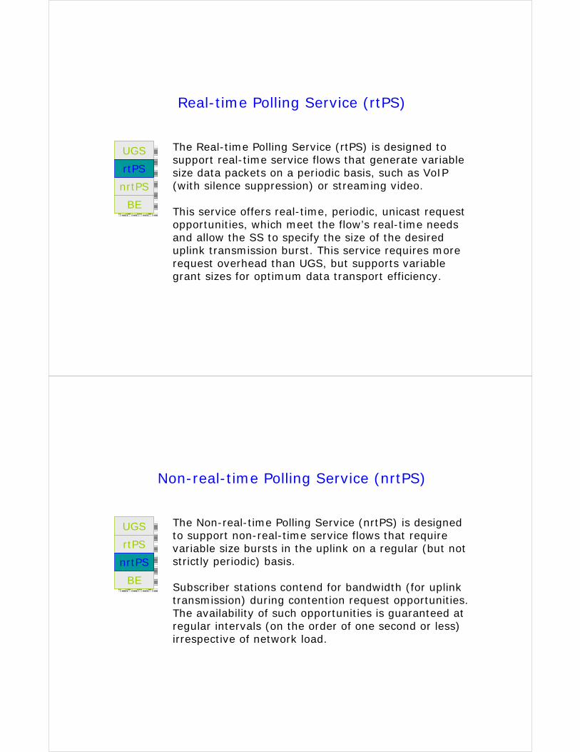
Real-time Polling Service (rtPS)
The Real-time Polling Service (rtPS) is designed to support real-time service flows that generate variable size data packets on a periodic basis, such as VoIP(with silence suppression) or streaming video.
This service offers real-time, periodic, unicast request opportunities, which meet the flow’s real-time needs and allow the SS to specify the size of the desired uplink transmission burst. This service requires more request overhead than UGS, but supports variable grant sizes for optimum data transport efficiency.
UGSUGS
rtPSrtPS
nrtPSnrtPS
BEBE
Non-real-time Polling Service (nrtPS)
The Non-real-time Polling Service (nrtPS) is designed to support non-real-time service flows that require variable size bursts in the uplink on a regular (but not strictly periodic) basis.
Subscriber stations contend for bandwidth (for uplink transmission) during contention request opportunities. The availability of such opportunities is guaranteed at regular intervals (on the order of one second or less) irrespective of network load.
UGSUGS
rtPSrtPS
nrtPSnrtPS
BEBE
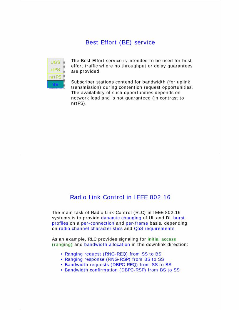
Best Effort (BE) service
The Best Effort service is intended to be used for best effort traffic where no throughput or delay guarantees are provided.
Subscriber stations contend for bandwidth (for uplink transmission) during contention request opportunities. The availability of such opportunities depends on network load and is not guaranteed (in contrast to nrtPS).
UGSUGS
rtPSrtPS
nrtPSnrtPS
BEBE
Radio Link Control in IEEE 802.16
The main task of Radio Link Control (RLC) in IEEE 802.16 systems is to provide dynamic changing of UL and DL burst profiles on a per-connection and per-frame basis, depending on radio channel characteristics and QoS requirements.
As an example, RLC provides signaling for initial access(ranging) and bandwidth allocation in the downlink direction:
• Ranging request (RNG-REQ) from SS to BS• Ranging response (RNG-RSP) from BS to SS• Bandwidth requests (DBPC-REQ) from SS to BS• Bandwidth confirmation (DBPC-RSP) from BS to SS
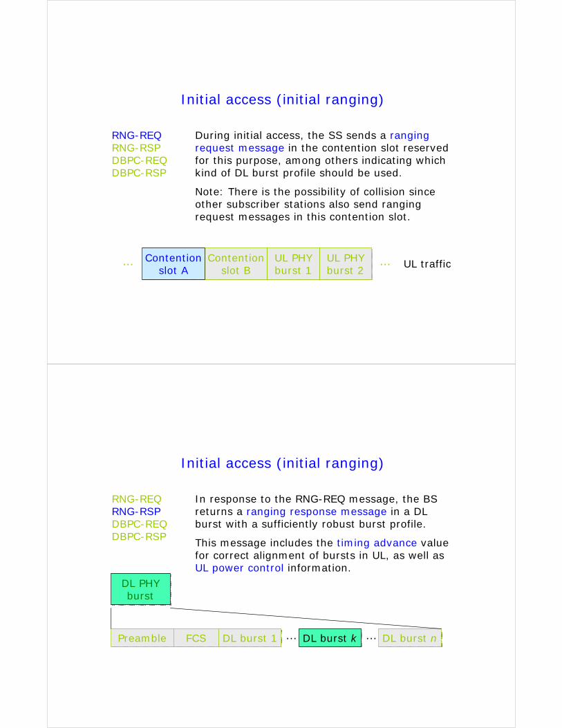
Initial access (initial ranging)
RNG-REQRNG-RSPDBPC-REQDBPC-RSP
Contentionslot A
Contentionslot A
Contentionslot B
Contentionslot B
UL PHYburst 1UL PHYburst 1
…… UL PHYburst 2UL PHYburst 2
UL traffic
During initial access, the SS sends a ranging request message in the contention slot reserved for this purpose, among others indicating which kind of DL burst profile should be used.
Note: There is the possibility of collision since other subscriber stations also send ranging request messages in this contention slot.
Initial access (initial ranging)
RNG-REQRNG-RSPDBPC-REQDBPC-RSP
In response to the RNG-REQ message, the BS returns a ranging response message in a DL burst with a sufficiently robust burst profile.
This message includes the timing advance value for correct alignment of bursts in UL, as well as UL power control information.
DL PHYburst
DL PHYburst
PreamblePreamble FCSFCS DL burst 1DL burst 1 DL burst nDL burst n…DL burst kDL burst k…

Contentionslot A
Contentionslot A
DL burst profile change
RNG-REQRNG-RSPDBPC-REQDBPC-RSP
Contentionslot B
Contentionslot B
UL PHYburst 1UL PHYburst 1
…… UL PHYburst 2UL PHYburst 2
UL traffic
The SS continuously measures the radio channel quality. If there is a need for change in DL burst profile, the SS sends a DL burst profile change request message in the contention slot reserved for this purpose, indicating the desired new DL burst profile.
DL burst profile change
RNG-REQRNG-RSPDBPC-REQDBPC-RSP
In response to the DBPC-REQ message, the BS returns a DL burst profile change response message confirming the new burst profile.
This is done in a DL burst with the old burst profile (when changing to a less robust DL burst profile) or using the new burst profile (when changing to a more robust DL burst profile).DL PHY
burstDL PHYburst
PreamblePreamble FCSFCS DL burst 1DL burst 1 DL burst nDL burst n…DL burst kDL burst k…


![wifi 802.11[1]](https://static.fdocuments.net/doc/165x107/55cf94c4550346f57ba4423c/wifi-802111.jpg)


![Purple WiFi Limited And [Customer] · Purple WiFi Limited And [Customer] ... the wireless fidelity technology based on the IEEE 802.11 ... forms part of Purple WiFi's security procedures](https://static.fdocuments.net/doc/165x107/5ad30c4e7f8b9afa798d6a69/purple-wifi-limited-and-customer-wifi-limited-and-customer-the-wireless.jpg)
