Wireless electrocardiogram trans- mission based on ultra ...
53
UPTEC E 18 010 Examensarbete 30 hp Juni 2018 Wireless electrocardiogram trans- mission based on ultra wideband radio Oskar Flink
Transcript of Wireless electrocardiogram trans- mission based on ultra ...
UPTEC E 18 010
Examensarbete 30 hpJuni 2018
Wireless electrocardiogram trans- mission based on ultra wideband radio
Oskar Flink

Teknisk- naturvetenskaplig fakultet UTH-enheten Besöksadress: Ångströmlaboratoriet Lägerhyddsvägen 1 Hus 4, Plan 0 Postadress: Box 536 751 21 Uppsala Telefon: 018 – 471 30 03 Telefax: 018 – 471 30 00 Hemsida: http://www.teknat.uu.se/student
Abstract
Wireless electrocardiogram transmission based onultra wideband radio
Oskar Flink
Ultra wideband (UWB) communications has been a subject of much discussion over the last decade. The method of UWB has had a hard time to establish itself among other methods such as Bluetooth and WiFi but as internet of things (IoT) gains a foothold in our daily lives, UWB has presented some new application areas. These application areas are, among other things, self driving cars, energy efficient data transfer, health care applications, sensor networks and real time location systems. This project aims to use UWB communications to real-world applications, specifically, electrocardiography (ECG) - an application in health care in this project, and develop a prototype for the application. The prototype consists of two Android smart phones and two UWB modules (EVK1000 evaluation kits from DecaWave, Inc). Each smart phone connects a UWB module so that the two smart phones, one as sender and the other as receiver, can communicate directly through UWB radios. This is intended to serve as a proof-of-concept that UWB devices are well suited for short range data transfer applications. The result achieved by the project is an android application along with sending and receiving programs for the development boards by Decawave and additional information regarding UWB and its uses. The results also include a comparison of UWB, Bluetooth and WiFi as of todays standard. The goal of the project is to learn how android applications are programmed, how UWB is used in todays technology and how to program and use development boards presented by companies. The prototype has been built and shown that 12-lead simulated ECG signals from the sender can be transfered to the receiver through the UWB communications. The work includes programming (in C) the two UWB modules for UWB communications, and Java for the android applications (programs) on the smart phones. The Android application is handling transmission of ECG signals to the sending UWB module and then receiving them from the receiving UWB module as well as displaying them on the receiver.
The future work to continue the present project is to replace the sending smart phone by an ECG device that sends real ECG signals.
Tryckt av: UppsalaISSN: 1654-7616, UPTEC E18 010Examinator: Tomas NybergÄmnesgranskare: Ping WuHandledare: Håkan Sjörling

Sammanfattning
I dagslaget finns det manga olika satt att skicka information tradlost, de vanligastesatten ar WiFi och Bluetooth men en mindre utforskad teknik ar Ultra-Wideband,UWB. Det ar en teknik som blir mer och mer popular att anvanda mellan apparatersom inte behover lang rackvidd och samtidigt vill sanda mycket information. En avteknikens storsta fordelar ar att den ar valdigt energieffektiv vilket passar bra till portablaapplikationer. Nagra av dessa applikationer ar sjalvkorande bilar, lokaliseringssystem,medicinala losningar och tradlos dataoverforing.
I det har projektet beskrivs hur tekniken for UWB fungerar och vad den kananvandas till. For att visa anvandningen praktiskt har en prototyp for sandning avEKG-signaler mellan telefoner med hjalp av UWB har tagits fram. EKG, eller ECGstar for electrocardiography och ar en sorts hjartovervakning som lakare anvanderfor att hitta onormala hjartslag och hjartflimmer. Tanken bakom prototypen ar att enpatient ska kunna ta ett ECG under langre tid. Informationen ska tradlost skickas tillen telefon sa att patienten inte ska behova ta upp lakartid och kunna bara den utan attvara bunden till en plats.
Prototypen bestar av tva Android smartphones som ar kopplade till tva UWB-sandare. Kommunikationen mellan telefonerna och sandarna anvander USB och kom-munikationen mellan sandarna anvander UWB. Detta for att telefoner inte stoder UWB-kommunikation an, vilket gor att en extern sandare ar nodvandig. Sandarna sitter pautvecklingskort fran Decawave kallat EVK1000 och dessa skoter all den tradlosa kom-munikationen.
Nar sandningen gors mellan telefonerna simuleras ECG-signaler i ena telefonen,skickas till UWB-sandaren som skickar det vidare till mottagaren. Hos mottagaren ritasdessa signaler ut i telefonen och anvandaren kan da latt se hur dessa ser ut. Signalernasimuleras istallet for att fysiska matningar tas pa grund av att dessa ar svara att gora.Det kraver valkalibrerad utrustning och utan sadan utrustning ar det svart att faststallaatt signalerna kommer fram korrekt.
Tanken med projektet ar att visa hur UWB kan anvandas som ett sandningsmediumoch grundligt visa en praktisk applikation till detta. Att anvanda UWB inom medicinalalosningar ar ett steg till att fa mer energieffektiva apparater med langre batteritid ochsamtidigt ha en saker overforing av information. Detta kan i framtiden stracka sig langrean bara ECG och skulle kunna anvandas till att skicka vilken data som helst.
Resultatet av projektet blev en android-applikation som kan kopplas upp till De-cawaves EVK1000 utvecklingskort. Detta kort har programmerades till att kunna tahand om informationen som skickas fran android-applikationen och hantera meddelanden
i

som skickas mellan tva utvecklingskort. Applikationen innehaller menyer for att sattaupp USB-kommunikationen och hanteringen av denna. Den kan skicka ut ECG signalerover tolv kanaler som sedan ritas upp i tolv olika fonster hos mottagaren. I rapportentas aven for- och nackdelar om UWB upp och en jamnforelse med Bluetooth och WiFihar genomforts for att visa skillnaderna mellan dessa protokoll som motivation till varforjust UWB passar bra till detta andamal.
Malet med projektet och rapporten ar att visa att UWB lampar sig for manga olikaapplikationer, bland annat ECG-signalhantering som anvands inom sjukvarden. Maleninnefattar aven att bygga forstaelse inom Androidprogrammering, programmering avutvecklingskort och tradlos kommunikation. Den ger aven insikt i hur protokoll anvands,i detta fall IEEE 802.15.4-2011 samt hur projekt likt detta kan laggas upp och hanteras.Projektet har legat som grund till fler andra projekt som pabyggnad av ECG-hanteringoch aven distansmatning med hjalp av UWB.
ii

Acknowledgements
I would like to give a special thanks to Ping Wu, Hakan Sjorling, Andreas Gawerth,Viktor Stahl, Maria Toll and Tommy Holmberg for their support during this project.
iii

Contents
1 Introduction 11.1 Background . . . . . . . . . . . . . . . . . . . . . . . . . . . . . . . . . . 11.2 Overview . . . . . . . . . . . . . . . . . . . . . . . . . . . . . . . . . . . . 31.3 Objectives . . . . . . . . . . . . . . . . . . . . . . . . . . . . . . . . . . . 31.4 Tasks and scope . . . . . . . . . . . . . . . . . . . . . . . . . . . . . . . . 4
1.4.1 Tasks . . . . . . . . . . . . . . . . . . . . . . . . . . . . . . . . . . 41.4.2 Limitations . . . . . . . . . . . . . . . . . . . . . . . . . . . . . . 4
1.5 Outline . . . . . . . . . . . . . . . . . . . . . . . . . . . . . . . . . . . . . 5
2 Theory 62.1 Electrocardiogram . . . . . . . . . . . . . . . . . . . . . . . . . . . . . . 62.2 Ultra wideband (UWB) communications . . . . . . . . . . . . . . . . . . 7
2.2.1 Signals of UWB, wideband and narrow band . . . . . . . . . . . . 72.2.2 Spectrum . . . . . . . . . . . . . . . . . . . . . . . . . . . . . . . 82.2.3 Path loss models . . . . . . . . . . . . . . . . . . . . . . . . . . . 102.2.4 Interference and noise . . . . . . . . . . . . . . . . . . . . . . . . 102.2.5 Modulations . . . . . . . . . . . . . . . . . . . . . . . . . . . . . . 112.2.6 Multiple access . . . . . . . . . . . . . . . . . . . . . . . . . . . . 112.2.7 Error correcting . . . . . . . . . . . . . . . . . . . . . . . . . . . . 132.2.8 Communications protocols . . . . . . . . . . . . . . . . . . . . . . 15
2.3 UWB Ranging protocol . . . . . . . . . . . . . . . . . . . . . . . . . . . . 19
3 Implementation 203.1 System overview . . . . . . . . . . . . . . . . . . . . . . . . . . . . . . . 203.2 Hardware . . . . . . . . . . . . . . . . . . . . . . . . . . . . . . . . . . . 21
3.2.1 Android devices . . . . . . . . . . . . . . . . . . . . . . . . . . . . 213.2.2 EVK1000 evaluation kit . . . . . . . . . . . . . . . . . . . . . . . 22
3.3 Software and development tools . . . . . . . . . . . . . . . . . . . . . . . 253.3.1 Android Studio . . . . . . . . . . . . . . . . . . . . . . . . . . . . 253.3.2 CooCox IDE . . . . . . . . . . . . . . . . . . . . . . . . . . . . . . 253.3.3 MATLAB . . . . . . . . . . . . . . . . . . . . . . . . . . . . . . . 26
3.4 Implementation . . . . . . . . . . . . . . . . . . . . . . . . . . . . . . . . 273.4.1 EVK1000 programming . . . . . . . . . . . . . . . . . . . . . . . 273.4.2 Android Application . . . . . . . . . . . . . . . . . . . . . . . . . 32
iv

4 Results and discussion 364.1 Prototype . . . . . . . . . . . . . . . . . . . . . . . . . . . . . . . . . . . 364.2 Performance . . . . . . . . . . . . . . . . . . . . . . . . . . . . . . . . . . 36
4.2.1 Data rate . . . . . . . . . . . . . . . . . . . . . . . . . . . . . . . 374.2.2 Latency . . . . . . . . . . . . . . . . . . . . . . . . . . . . . . . . 374.2.3 Energy consumption . . . . . . . . . . . . . . . . . . . . . . . . . 38
4.3 Android application . . . . . . . . . . . . . . . . . . . . . . . . . . . . . . 384.4 Problems and solutions . . . . . . . . . . . . . . . . . . . . . . . . . . . . 384.5 Comparison of wide and narrow band communication . . . . . . . . . . . 39
5 Conclusion and future work 41
References 43
v

Abbreviations and definitions
Acronym DefinitionAB Aktiebolag, corporationACK Acknowledged frameADC Analog to Digital converterALOHA Multi access methodASCII American Standard Code for Information InterchangeAWGN Additive White Gaussian Noiseb BitB ByteBLE Bluetooth Low EnergyBPM Burst Position Modulation, see PPM.BPSK Binary Phase Shift KeyingBT BluetoothCDMA Code division multi-accessCRC Cyclic redundancy check, error detecting codedB DecibeldBm Milli decibelECC Error correcting codeFCC Federal Communications ComissionFDMA Frequency Division Multiple AccessFEC Forward error correctionGUI Graphical User InterfaceIDE Integrated Development EnvironmentIEEE Institute of Electrical and Electronics EngineersIoT Internet of ThingsMAC Media Access layerMHR MAC headerNACK Not acknowledgedOSI Open system interconnectionPHR PHY headerPHY Physical layerPPM Pulse Position ModulationPRF Pulse repetition frequencyRLTS Real Time location systemsRS Reed-Solomon error correction code
vi

SECDED Single-Error-Correct Double-Error-detectSFD delimiterSHR Synchronization headerTDMA Time Division Multiple AccessUSB Universal Serial BusUWB Ultra Wide BandW WattWiFi Wireless Network 802.11 standard
vii

1 Introduction
1.1 Background
Electrocardiography (ECG) is often performed in a hospital. This occupies the doctorand it is also costly to keep patients with long term heart monitoring in hospital care.The idea behind this thesis project is to create a wireless communication solution thatwould make the ECG device easier to wear for extended periods of time to monitorheart activity. Several sensors are used when performing an ECG meaning that lotsof data needs to be sent to a base unit which, in this case, is a smart phone. UWBcommunications and ranging have attracted lots of interest of academia and industriesbecause it has many advantages:
• High time resolution for precise localization
• High energy efficiency
• Range/bitrate scalability
• Robust to interference and multipath
• Difficult to intercept (in traditional ways)
• Radio suitable for wireless sensors.
UWB has been researched extensively in theory but not so much in experiment.With the advent of commercially available UWB transceiver IC chips, e.g., DecaWave’sIC chip, DW1000 [1], much interest in UWB communications and ranging has, duringthe past two or three years, been shifted to realization and implementation. DecaWaverecently claimed that they are going to integrate their UWB chips in smart phonesin the near future. Thus, it is possible to use UWB radios to direct communicationsbetween smart phones, which is called device-to-device (D2D) communications; andcommunications of a smart phone with UWB-based wireless sensor networks, which issuitable for the Internet of things (IoT). The D2D communications can relieve the largerradio stations as much of the traffic is sent within a smaller area. The UWB-based sensornetworks can be used for applications such as life monitoring and it can be set up insmaller networks that only communicates with one main unit, a smart phone, that canin turn communicate with the outside world through WiFi or 3G/4G. Using UWB willalso make these smaller networks easier to make portable compared to WiFi as it’s moreenergy efficient and the devices can run much longer on battery using UWB.
1

Other applications include D2D communications in mobile phones used in text mes-sages and cellphone calls that uses UWB instead of the ordinary cell network. Anotherapplication of UWB device-to-device could be large festivals where lots of people aresituated and data traffic can be very heavy.
The project is done in collaboration with a company called Syntronic AB in Gavlewhich is a company that produces electronics as consultants for other companies.
2

1.2 Overview
The project is realised with two smart phones connected via USB to two developmentcards. As of today (2018), very few phones support UWB transmission so the phones needto connect a stand alone module to handle the UWB transmission. The transmitter andreceiver communicates via USB to the UWB modules and the modules communicatesvia UWB with each other. As seen in Figure 1.1 the complete system has four mainmodules, two phones and two UWB modules
T
R
USB cable
USB cable
UWB node
UWB node
Smart phone transmitter
Smart phone receiver
Figure 1.1: Brief overview of setup. Schematic of the project setup showing the directcommunications of two smart phones through UWB communications. The transmittingsmart phones (T) is connected to a UWB module, and the receiving smart phone (R) isconnected to another UWB transceiver.
1.3 Objectives
The thesis project aims to investigate a energy efficient wireless method of sending andreceiving data using UWB communications. Other candidates for this purpose are WiFiand Bluetooth. The messages sent between the smart phones are electrocardiogramsignals, ECG signals, which are simulated and sent from one Android device to anothervia the evaluation kit EVK1000 from Decawave. The setup will serve as a proof ofconcept that UWB can be used to send streamed data as well as to provide a goodfoundation for future work with Decawave products. It will also serve as a comparisonbetween other wireless technologies.
3

1.4 Tasks and scope
This master thesis project will investigate how a given signal, in this case ECG, can besent over multiple channels. The suggested method to be used is to send over multiplefrequencies and then filter the signal in the receiving end using wide band-pass filters.The signal is to be simulated in MATLAB, sent via the analog sound and received via anADC to the development cards as to simulate how a real ECG signal would be acquiredfrom probes on a patient.
1.4.1 Tasks
For this project a literature study will be the first step, after that familiarization of thetesting equipment for the different technologies is necessary to find out how to designand implement the modules to create a system that can measure and process data andthen send that data wireless.
• Literature study, investigate the following:
– Current technology with ECG.
– Ultra Wideband, WiFi and Bluetooth.
– Energy cost in the different technologies.
• Design an Android application to send/receive data through USB.
• Program EVK1000 board to handle USB messages and sending them between thetwo cards.
• Measure/calculate performance of EVK1000 for indoor data transmission.
1.4.2 Limitations
Before the project was started some of the proposed limitations were that UWB hadnot been researched as much as other wireless communication techniques, e.g., WiFi orBluetooth. Thus there are not much support and working prototypes available. Thetools presented to realise the project were two smart phones, two EVK1000 evaluationkits that contains UWB transceivers and the necessary wired connections between themas seen in Figure 1.1.
During the project many hardware related problems were presented. The mostproblematic problems were that the EVK1000 did not support multichannel transmissionas first proposed. The EVK1000 can only send on one channel and receive on a different
4

(if required). The EVK1000 can not receive analog input either. Proposed solutionto this is to simulate the signals and directly send them via USB from the Androidapplication.
1.5 Outline
The report is structured so that the reader can get all the required information regardingthe theory in section 2, how the project was implemented in section 3 and the resultsalong with discussion regarding the work process of the project is handled in section 4.
The Theory section first introduces what an ECG is and how it’s used in todaystechnology. After that it takes up what UWB is and how such signals are sent. It alsotakes up which communication protocols are used.
The Implementation section shows how the hardware was connected and used, aswell as showing the software used in the project. The programming of the Android deviceas well as the programming of the development cards are presented here as well.
5

2 Theory
2.1 Electrocardiogram
An electrocardiogram is a way to measure electric activity of the heart. This is doneusing electrodes placed directly on the skin that detects changes that forms when theheart pumps blood. The detected change comes from polarization of the blood cells thatproduces a measurable voltage. An ECG performed by a physician is usually called a12-lead ECG, it uses 10 electrodes that measures 12 different voltages. For this projectup to 12 channels of data can be sent and recorded to simulate the 12 channels in areal ECG. An ECG can be used to detect heart deceases and irregularities within theheart. A typical ECG signal can be seen in Figure 2.1. The ten electrodes have to beconnected to a central unit that measures the waveforms so the need for conductingwires would still be a problem but the central unit can be manufactured very small andenergy efficient. The measured voltage from an electrode is very small (microvolts) andthus the central units contains one or several amplifiers to amplify the different signals.These amplifiers are very noise resistant. The ECG central unit also contains differentfilters needed in order to get a cleaner signal.
The application of a wireless ECG is to detect heart defibrillation in patients thatneed long term monitoring. The patient would carry the ECG for an extended time andthe ECG device would send data wireless to a central unit, for instance a smart phonewhich could forward it to a server or directly detect irregularities.
Today there are already companies that produces wireless ECG units that commu-nicate with WiFi or Bluetooth and the usage or UWB as a medium of transmission hasbeen done in research groups, however, no commercial product that uses UWB could befound. Some of these companies are LifeSync(WiFi), IMEC and V&Hecg(WiFi).
0 0.2 0.4 0.6 0.8 1 1.2 1.4 1.6 1.8 2
Time
0
0.5
1
1.5
Vo
lta
ge
ECG Signal
Figure 2.1: ECG signal waveform for one channel.
6

2.2 Ultra wideband (UWB) communications
Ultra wideband, UWB, is as the name suggests, a method of sending information wirelessthat occupies a large bandwidth. It is a method that has a low energy cost and a lowrange. Like most wireless communication it uses electromagnetic waves that propagatethrough the air to convey information. It uses very short impulses to send informationwhich gives it a very large bandwidth. The bandwidth of a UWB signal is typically>500MHz and is situated in the 3.1-10.6GHz spectrum as first governed by the FCC [2].
2.2.1 Signals of UWB, wideband and narrow band
UWB signals are sent as short pulses over an order of nano seconds depending on thedesired frequency. The pulse is a sinusoidal pulse that can be modulated differently fordifferent signals. Other radio technology uses continuous signals that are modulated infrequency (fm) instead of short pulses. The short pulses is what makes UWB get itslarge bandwidth and low energy consumption.
2.2.1.1 UWB signal waveform
UWB pulses are constructed of a toneburst with a Gaussian envelope and of other shapedenvelopes but the Gaussian envelope is commonly chosen as it does not bleed over (lessenergy outside the desired bandwidth) into neighboring spectrum as much as for instancea rectangular pulse [3]. A pure sinusoidal pulse also bleeds over but a Gaussian pulsebleeds very little into neighboring spectrum. Gaussian signals also retain their form fromtime domain into frequency domain. This can be seen in Figure 2.2.
Shorter pulses have wider bandwidth which can be seen in Figure 2.2. In Figure 2.2the signal is a UWB pulse with two different frequencies and their respective bandwidth.The radio signal bandwidth is defined as the width between a lower and upper cutofffrequency. The cutoff frequencies are defined as the point where the signal gain is 3dB( 1√
2= 70.1%) below the maximum value of the frequency response. For some signals,
as UWB the cutoff frequency is defined as the point where the signal is 10dB below themaximum frequency.
To calculate the bandwidth of a wideband signal the two cutoff frequencies arerequired.
%B = 200 ∗ fH − fLfH + fL
(1)
where fH and fL is the high and low cutoff frequency.
7

−5 −4 −3 −2 −1 0 1 2 3 4 5
x 10−6
−1
−0.5
0
0.5
1
Time [s]
Am
pli
tude
UWB pulse
1MHz
10MHz
0 1 2 3 4 5 6 7 8 9 10
x 106
0
0.5
1
Frequency [Hz]
Am
pli
tude
UWB bandwidth
10MHz
1MHz
Figure 2.2: Bandwidth showing the difference between a short and longer pulse, theamplitude is normalized.
2.2.2 Spectrum
As UWB occupies large portions of the usable spectrum it also intrudes on licensedfrequencies. There are a few frequencies that can be used freely by anyone and typicallythese spectrum are occupied by wireless appliances such as Bluetooth, wireless phonesand WiFi. Using the licensed space is an illegal action and must thus be avoided.However, regulations for Europe state that the power of wide band signal has to beunder -41.3dBm/MHz [4], the limit where other channels would classify it as noise. [3].The unlicensed spectrum can be seen in Figure 2.3 and it shows the different bandsthat can be used for narrow band and UWB applications. The main spectrum usedin narrow band are 900-930 Mhz for GSM (not shown in figure), 2.400-2.483 Ghz forBluetooth, WiFi and other wireless appliances and 5.15-5.35 for WiFi 5G and newerwireless appliances.
2.2.2.1 Narrow band versus wide band
Traditionally radio transceivers have sent out signals with a small bandwidth and receivedthese with a narrow band filter to filter out all the unwanted frequencies. This is howradio works and when tuning in on a specific frequecy you tune this narrow band filter to
8

Figure 2.3: Licensed and unlicensed spectrum and available UWB frequency allocation
a specific carrier frequency. The amount of data you can send is limited by the width ofthe band you are using. They are also prone to interference from reflections (multipathfading) and are more easily jammed. [5]
Wide band signals have a much larger bandwidth and they are not prone to multi-path fading in the same extent as traditional radio signals. This is because UWB usesvery short pulses instead of continuous sinusoidal signals. The received signals are alsoreceived in small time windows which is what makes them a bit more resistant to multi-path fading. It is harder to detect and jam UWB signals because of their low range andlow energy density. The downside to this is the intensity of the signals are very low.This comes from the regulations for sending and receiving radio signals.
2.2.2.2 Future for wide band
Using wide band instead of narrow band in the future seems like a more reliable solutionthan using narrow band. Most bands are licensed and those that are not are getting in-creasingly crowded. Almost all sending protocols for home appliances such as Bluetooth,wireless phones and keyboards and IEEE 802.11(WiFi) uses an unlicensed narrow bandaround 2.4GHz. This narrow band is getting increasingly crowded as more and moredevices are connecting as part of Internet of Things. Many appliances are starting to usethe next unlicensed spectrum at 5.1GHz but this space will also become overcrowdedin the future. This problem can be solved with increasingly complex modulation oralternatively allocating more unlicensed spectrum for home appliances. Using licensed
9

spectrum is only permitted if the sending power does not interfere with other users inthat spectrum.
2.2.3 Path loss models
The path loss model describes how signal power decreases for increasing distance. Ithas three components, path loss, shadowing and multi path. Path loss describes onlyhow the power decreases over distance. Shadowing describes how a signal is blocked byobjects between sender and receiver, meaning how different frequencies are attenuatedfrom sender to receive. When a radio channel has almost no attenuation for a certainfrequency it is called deep fading meaning that the signal can’t be detected by thereceiver. This happens both in time domain and in frequency domain causing the signalto have to be re-sent occasionally. Multi path fading is the interference of your ownsignal due to multiple paths of the signal arriving at slightly different times.
UWB is subjected to path loss as much as any radio signal, which is reduced as 1/r2
which comes from the free space model [5]. Shadowing is a fading that is not affectingUWB too much as UWB signals have such a wide bandwidth. This is because shadowingblocks certain frequencies more than others and as UWB has a large bandwidth allocatinga wide spectrum the chances of the signal getting through is higher than for a narrowband transmission. This means that UWB works especially well indoor for distancemeasurements as the signals goes well through walls. UWB suffers a bit from multi pathfading (not as much as continuous signals). This has been solved by the receiver byusing a preamble signal that models the multi path fading and uses it to attenuate thesignal instead of interfering [1]. This works especially good indoors as parts of the signalreflects well of flat surfaces like walls and floors. The largest downside to UWB is thelow intensity of the signal which is why it has such low range
2.2.4 Interference and noise
Like all electromagnetic waves UWB also gets interfered from other devices. UWB usesa very limited amount of energy as it has to follow the FCC regulations [2] meaningthat it is strongly interfered with other devices. This is solved with special receivers andlong preamble codes that identifies other UWB devices. The noise a signal experiencescan be modeled as AWGN, additative white Gaussian noise. White Gaussian noise is adisturbance that is deployed over all frequencies. This model is used as it closely resemblethe actual noise a system experiences but it’s not perfect as it’s impossible to estimatethe noise exactly. The noise comes from all electric devices and background radiation.
10

2.2.5 Modulations
The modulation scheme used for sending the UWB signals is a combination of BPSKand BPM. For the preamble (first part of UWB transmission) single pulses are sent withthree outputs, +1 for 0◦ phase, -1 for 180◦ or 0 for no signal. These pulses are rapidlysent so the preamble takes very little time to send.
2.2.5.1 BPSK (Binary phase-shift keying)
When a signal is sent a string of bits has to be modulated into sinusoidal signals thatcan be sent wireless. This is done by assigning the phase of the sent signal to either a 1or 0. The easiest case of this is where each bit is represented by either 0◦ or 180◦ phaseshift in the sinus signal. This then maps to ± 1 in the Re/Im plane. This means thatif the sender wants to send a 1, a sinus signal with carrier frequency fC is modulated sothat it has 0◦ phase shift. A zero is sent the other way around with 180◦ phase shift.
The receiver can demodulate this signal by mapping the received bit so that allsignals > 0 is mapped to 1 and similarly all signals < 0 is mapped to 0.
2.2.5.2 BPM/PPM (Burst/Pulse position modulation)
Burst position modulation, also called pulse position modulation is a modulation thatuses time to determine if the sent signal is 0 or 1. This is done by having a time frame,called symbol interval, divided into four parts as seen in Figure 2.4. The positionsrepresent different time delays. If the burst is sent at the beginning of the frame (nodelay) the received symbol is a zero or if it’s sent in the third interval (delayed) thesymbol is a one.
Burst/pulse =0
Guardinterval
Burst/pulse =1
Guardinterval
Figure 2.4: One time frame in BPM/PPM, the symbol time.
2.2.6 Multiple access
In order for multiple users to be able to access the same medium several different tech-niques are used. These techniques have been developed and deployed as the market forradio communications grew and usually a new generation of telecommunications was
11

born when a new method was found and implemented (GSM(2G), 3G, 4G). The methodused in this project is a combination of TDMA and CDMA/FDMA along with theALOHA access method. As there are only two users in the scope of the project theCDMA/FDMA only applies if multiple users try to access the same receiver or sender.The sender and receiver operates on a set frequency band with a set code and sendsinformation in a TDMA fashion, if multiple users access at the same time the ALOHAprinciple will be used.
2.2.6.1 ALOHA access method
The ALOHA access method is a random access method first deployed at the universityof Hawaii that allows multiple users to send over the same medium. It dictates thata user can send whenever they want and the receiver receives everything all the time.The sender will begin transmission and wait for an ACK, meaning that the package hasbeen correctly sent. If multiple users send packages at the same time the receiver willget collided, garbled data and will not send any ACKs to the senders (unless one of themessages can be recovered with ECC). The senders will then wait and resend their dataafter a time t = tpackage + δ where tpackage is the time it takes for one package to besent and δ is a randomly generated delay that prevents other users from colliding again.If multiple collisions occur the time to resend a package becomes longer and longer.ALOHA is deployed in many applications but it can be very inefficient if the number ofusers become too large. The expected throughput of an ALOHA system:
T = Le−L, L = λτ (2)
Where T is the expected throughput and L is described as the packet rate λ, times packettransmission time, τ [5].
2.2.6.2 FDMA (Frequency-Division Multiple Access)
To send multiple arrays of data simultaneously frequency-division multiple access, FDMA,is used. It is a method that divides the available spectrum, also called channel, intosmaller bands, or sub channels to send data over the different channels. This is the mostcommon way of multiple-access used today. A spectrum is divided equally into N chan-nels where each sub channel is allocating a bandwidth and some guard band. The guardband is necessary to reduce interference between channels due to Doppler shift(due tomovement) and leakage between channels. Ideally you would want each sub channel tobe square shaped in the frequency domain with as little guard band as possible to notwaste bandwidth. In reality the sub channels overlap, bleeding over into other channelsbut with very low energy. This method is very useful but because of deep fading you can
12

get some channels that get very good data rate and some with really bad. To preventall data in one array from getting lost the different data arrays are divided into smallerarrays which are sent on different sub channels. Doing this with error correcting codemeans that much of the data can be retrieved even if one channel is completely offline.To receive FDMA signals multiple filters are required to distinguish the different chan-nels. This method also has the disadvantage that multiple channels can bleed over anda finite amount of data streams can be used at the same time.
2.2.6.3 TDMA (Time-Division Multiple Access)
TDMA uses empty spaces in time to send multiple arrays of data in the same channel.The method divides a finite amount of time into equally long time frames that send smallamounts of data in each time frame. This method also need some guard time to allowall multi path interference to fade. TDMA can support a very large amount of users atthe same time but with lower bitrate as the number of users get larger. This method issensitive to timing and if you get timing problems you might end up with lots of guardtime and a very low data rate. Both the sender and receiver needs to be synchronized.
2.2.6.4 CDMA (Code-Division Multiple Access)
CDMA is another way of dividing multiple arrays of data to be sent simultaneously. Thisis done by letting each sender and receiver have a unique code, also called orthogonalcoding. All senders encode their data with their unique code before all the data is sentat the same time. The receivers get the whole signal with all the data but they alldecode the datastream to get the correct sender. This method can be used over anygiven frequency and time frame. This means that the data spectrum is very efficientlyused with CDMA.
Analogy: A room full of people speaking different languages all speak at roughlythe same volume and frequency. For one person to talk to the others he needs to speakthe same language as the other person, it wont matter if he raises his voice or speak ina higher pitch, the other user wont understand him.
2.2.7 Error correcting
To correct and detect errors in transmitted messages there are many different techniques.Two of these are SECDED and CRC which can both detect errors but only one of themcan correct errors.
13

2.2.7.1 SECDED (single-error-correct, double-error-detect)
SECDED is the abbreviation for a Hamming code that can detect two errors in asequence and correct one of them. The code is a linear block code that adds extraparity bits to a message that checks if the message has been received correctly. The codemakes the sent message longer so the total amount of bits sent is longer and it works bestin a system where few errors occur. This is used in the PHY header as seen in section2.2.8.2. The parity bits are generated by using the other bits in the data message. Eachparity bit uses specific bits in the data message where the first uses every other bit, thesecond uses every 2 bits, 3rd every 4th and so on. The used bits are put through anXOR gate to generate the new bits.
Example: We want to encode the message 10110001, we generate parity bit P1,P2, P3 and attach them to our message. These can be used to detect if any of theaffected bits are wrong with the most significant being represented more times than theleast significant. The messages can be decoded by calculating the parity bits in thereceiving end and compare them to the received parity bits. If they don’t match up theposition of the incorrect bit can be calculated and changed. The encoded message willbe 10110001001.
P1 = XOR(bit1, bit3, bit5, bit7) = XOR(1, 1, 0, 0) = 0
P2 = XOR(bit1, bit2, bit5, bit6) = XOR(1, 0, 1, 0) = 0
P3 = XOR(bit1, bit2, bit3, bit4) = XOR(1, 0, 1, 1) = 1
2.2.7.2 CRC (Cyclic redundancy check)
Cyclic redundancy check is a method that’s easy to implement and very time efficient. Itis an error detecting code meaning that it only detects if an error has occurred duringtransmission but it does not correct the error. This is a very reliant code that can detectup to 99% of all errors but it cannot detect intentional errors. It is very popular and usedin many systems such as USB, mobile networks and RFID transmissions. The code usesXOR circuits and shift registers to generate a code that depends on the sent message.Every message will have its own code. This code is appended to the message as 1 to 64bits depending on the safety required.
The code is generated by using a divisor, a short code that both the sender andreceiver knows. This code is shifted through the message from most significant bit toleast significant bit. When the divisor has been shifted through the whole message theremainder will be the CRC code. This is appended to the end of the message and thereceiver can easily do the same calculation to check if the remainder is 0, if it is 0 the
14

message has been sent successfully and the receiver can send an ACK. If it is not 0 thereceiver has to send back a NACK, not-acknowledged and the sender can resend thesame message.
2.2.8 Communications protocols
A message sent via the IEEE 802.15.4-2011 standard has three different headers whichcomes from the OSI model [6]. The OSI model specifies that there are seven layers fortelecommunications explaining how a message is sent from user input to sent bits. Thelower the number of the layer the more hardware related the layer is. For this projectsome of the lower layers have been used but most of that is done via the DW1000chip. The PHYsical layer is handled by the DW1000 chip while the MAC layer is partlyhandled by the chip and partly by the programmer. A typical message is sent with asynchronization header, SHR, physical header, PHY header, and a media access header,MAC header. This can be seen in Table 2.1. When multiple users access the samechannel the ALOHA method is defined as the standard in IEEE 802.15.4-2011 [7].
SHR PHR MHR DataSynchronization header Physical header MAC header Payload(64,1024,4096)+(8,64)symbols
19 bits max 37 bytes max 97-122 bytes
Table 2.1: The general format for UWB frames.
2.2.8.1 Synchronization header
The synchronization header is a made up of two parts, a preamble sequence and adelimiter called SFD (start of frame delimiter). The preamble code is a series of pulses(symbols) sent out before data transmission is sent so to synchronize the sender andreceiver. At the end of the preamble sequence the SFD tells the receiver that it shouldswitch from receiving symbols to receiving BPM/BPSK modulated signals instead. Thesender use this information to determine how the impulse response between sender andreceiver looks like. This means that the receiver can use the multipath fading to itsbenefit instead as interference and also to time how long it takes for the most direct pathto be received. Both the receiver and the sender has a preset preamble code that theyuse to determine this. The DW1000 has three different settings for this that is used inthis project. The pulse repetition frequency, PRF, that tells us how often the preamble
15

symbols are resent. The user may chose from 16MHz or 64MHz (default). The preamblecode, which there are four to choose from at 64MHz and two at 16MHz and lastly thepreamble length. A longer preamble length gives us a signal with longer reach but ittakes longer to send it as well.
2.2.8.2 PHY header
The IEEE 802.15.4-2011 standard PHY header consists of three main parts and is modu-lated with the BPM/BPSK modulation. It uses a Hamming error correcting code, ECC,to make sure the message header is properly received. The header is 19 bits long andconsists of data rate, frame length, ranging packet, header extension, preamble durationand the parity bits generated by the ECC as seen in Table 2.2.
General PHY header formatDatarate
Frame Length Rangingpacket
headerexten-sion
preambleduration
SECDED Bits
Table 2.2: PHY header attached to messages.
16
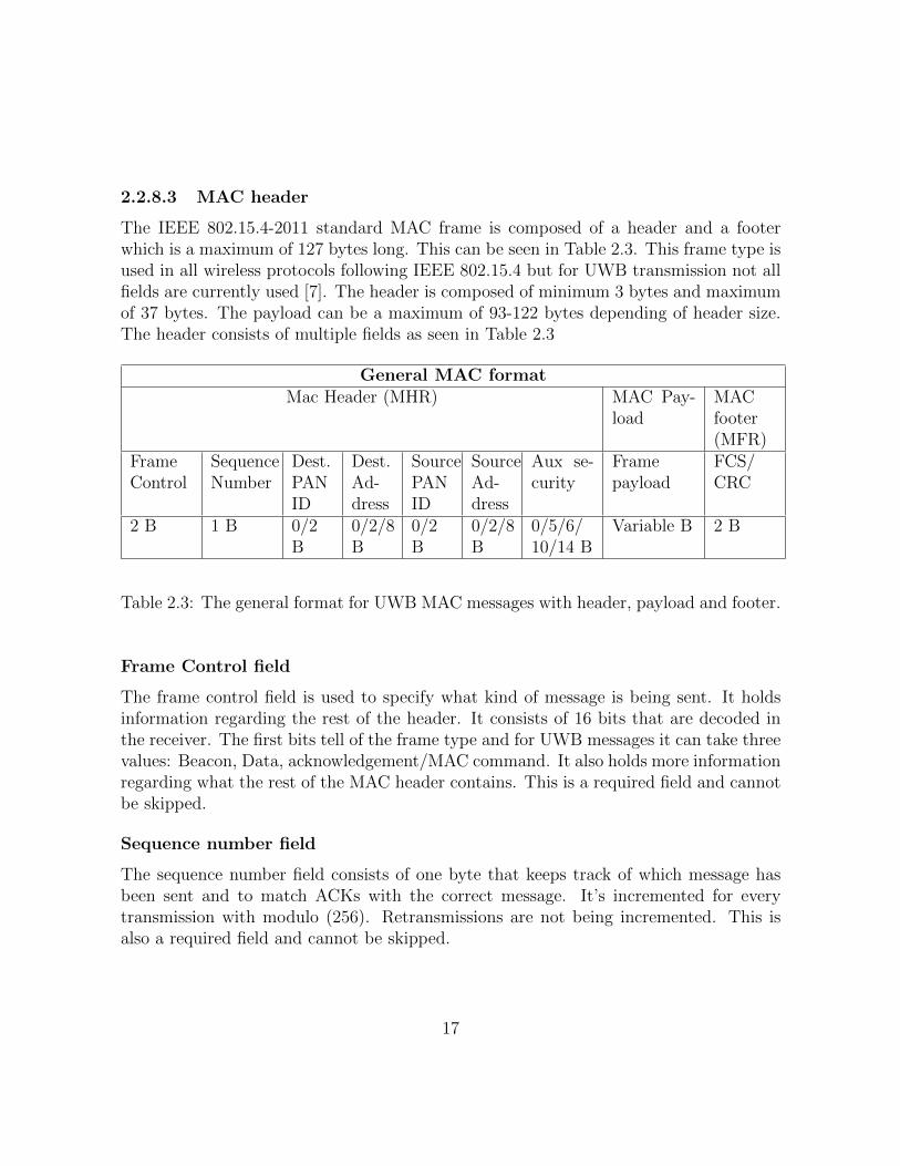
2.2.8.3 MAC header
The IEEE 802.15.4-2011 standard MAC frame is composed of a header and a footerwhich is a maximum of 127 bytes long. This can be seen in Table 2.3. This frame type isused in all wireless protocols following IEEE 802.15.4 but for UWB transmission not allfields are currently used [7]. The header is composed of minimum 3 bytes and maximumof 37 bytes. The payload can be a maximum of 93-122 bytes depending of header size.The header consists of multiple fields as seen in Table 2.3
General MAC formatMac Header (MHR) MAC Pay-
loadMACfooter(MFR)
FrameControl
SequenceNumber
Dest.PANID
Dest.Ad-dress
SourcePANID
SourceAd-dress
Aux se-curity
Framepayload
FCS/CRC
2 B 1 B 0/2B
0/2/8B
0/2B
0/2/8B
0/5/6/10/14 B
Variable B 2 B
Table 2.3: The general format for UWB MAC messages with header, payload and footer.
Frame Control field
The frame control field is used to specify what kind of message is being sent. It holdsinformation regarding the rest of the header. It consists of 16 bits that are decoded inthe receiver. The first bits tell of the frame type and for UWB messages it can take threevalues: Beacon, Data, acknowledgement/MAC command. It also holds more informationregarding what the rest of the MAC header contains. This is a required field and cannotbe skipped.
Sequence number field
The sequence number field consists of one byte that keeps track of which message hasbeen sent and to match ACKs with the correct message. It’s incremented for everytransmission with modulo (256). Retransmissions are not being incremented. This isalso a required field and cannot be skipped.
17

Destination and source PAN ID field
The PAN ID tells us who the target audience is, a value of 0xffff means broadcasting.This should be set the same for transmitter and receiver.
Destination and source Address field
The address tells us who sent and received the message. This should be set to a uniqueaddress in commercial use to ensure that the device does not conflict with other devices.A set of addresses can be bought from the IEEE Registration Authority to ensure thatdevices follow this.
Aux security header field
This is used if extra security is needed. It can be used to tell the receiver about theauthenticity of the message as to avoid receiving and processing messages from uniden-tified sources. This field is also used to describe which encryption should be used for themessage so the receiver can decode it correctly. In this project no security is used.
FCS Field
The FCS field stands for frame check sequence and it uses CRC coding to check for errorsin the transmitted message.
18

2.3 UWB Ranging protocol
Ultra wideband is currently used for short range data transfer but the main usage is toestimate range between two UWB transceivers. This is also DecaWaves modules mainusage. The ranging works well as the UWB waveforms travel well through walls indoorsand the pulses can be timed very accurately to give a ranging error or ±1dm which iswhy UWB’s main application is ranging. Ranging can also be done with Bluetooth orWiFi but this gives an error of several meters.
To get the range between two transceivers a pulse is sent from the sender (S) to thereceiver (R). When the pulse has been sent (S) starts a timer and (R) responds as soonas the pulse has been received. In this response (R) sends information about handlingtime for the pulse. Then (S) gets the message and stops the timer, the time of flight canthen be calculated as total time minus handling time divided by two to account for flighttime back and forth. (S) can then send the ranging information to (R) with a regularmessage. This can be seen in Figure 2.5
Sender ReceiverFirst pulse Timer T starts
Response contains handling time T_h
Response received Timer T stops Final time is calculated
Final time received
response
first request
final message
Figure 2.5: Calculating the time of flight between two UWB modules.
19

3 Implementation
3.1 System overview
The basic system for sending and receiving signals can be seen in Figure 3.1. Theoverview describes how a message travels from one sending user to receiving user. Thedifferent steps have been sub-divided into android applications and the EVK1000 devel-opment boards. The sender inputs a message that is put as the payload. This messagecan be either text message or data message. This message is configured to fit the USBpayload structure and sent via USB to the EVK1000 sending unit. The USB protocolhandles error checking which is done inside the libraries described in section 3.3. Oncethe message is handled by the EVK1000 the payload is given a IEEE802.15.4-2011 headerand sent via UWB to the EVK1000 receiver. The receiver then checks for errors andconfigure the message to be sent to the receiving application and the header is removedonce the UWB message has been received error free. The receiving application receivesthe message in the same format as the sender configured it and then handles the messageas desired.
Decode UWBmessage
Configuration USB
Data message Payload Configuration USB
S
Sender
UWBcommunications
Handling of USBmessage
Configuration UWB
Error check
USBcommunications
USBcommunications
Error check
Data message Payload Decode USB
R
Receiver
Error check
Android Application Receiver
Android Application Sender
UWB board EVK 1000 Sender
UWB board EVK 1000 Receiver
Figure 3.1: Overview of the communication system.
20

3.2 Hardware
3.2.1 Android devices
The Android devices used for the Android application in Figure 3.1 are a Samsunggalaxy S5 and an ASUS ZenPad C 7.0 (Z170MG). The specifications can be seen inTable 3.1. Both devices run android and supports USB connections but none of themsupport UWB communications [8], [9]. To be able to run the application they need torun at least Android 3.0.
Samsung Galaxy s5 Asus ZenPad
Device name Samsung Galaxy s51 Asus Zenpad C 7.02
Dimensions 142 x 72.5 x 8.1 mm 189 x 108 x 9.5 mm
Mobile Network GSM/HSPA/LTE GSM/HSPA
Communications
WiFi 802.11 a/b/g/n/acBluetooth 4.0microUSB 3.0GPS/NFC/IR
WiFi 802.11 a/b/g/nBluetooth 4.0microUSB 2.0GPS
Processor Quad-core 2.5 GHz Krait 400 Quad-core Cortex-A7
Operating system Android 6.0.1 Android 5.0
UWB support No No
Table 3.1: Specifications for Samsung Galaxy s5 and Asus ZenPad [8], [9].
1Image source: https://bit.ly/2I1W6Wb [10]2Image source: https://bit.ly/2HYJpvs [11]
21

3.2.2 EVK1000 evaluation kit
EVK1000 development board is made and developed by Decawave Ltd. It costs around$500 and should be used to test DW1000 UWB transceiver IC (integrated circuit) chiprather than being a complete product. The board is integrated with an ARM processor,several switches, an LCD screen along with the Decawave DW1000 chip and antenna.The development board comes with a standard open source program called DecaRangingwhich displays how far apart the two cards are. The board can be seen in Figure 3.2.
The ARM processor is responsible for all the calculations while the DW1000 chiptakes care of the sending and receiving of UWB signals. SPI is used between the DW1000and the ARM processor, this is a common protocol that smaller wired modules use toefficiently communicate.
Figure 3.2: Decawaves EVK1000 development board front and back showing LCD displayon the front and additional components on the back [12].
Other evaluation kits that could have been used are POZYX [13] or some of thenewer models developed by Decawave.
3.2.2.1 Micro controller STM32F105 ARM Cortex M3
The ARM micro processor is the programmable unit on the EVK1000, it has lots offeatures where some can be seen in Table 3.2. The processor has been developed bySTMicroelectronics and is programmed via their programmer/debugger ST-LINK/V2which connects to the computer via USB and to the processor via JTAG.
22

Processor name STM32F105RCT6
Dimensions 10 x 10 mm
Processor core (CPU) ARM 32-bit Cortex M3 CPU
Frequency 72 MHz max frequency
Memories64 to 256 Kbytes Flash memory64 Kbytes general purpose memory
Communications
I2C Interface x 2USART interface x 5SPI interface x3USB 2.0 x2Ethernet 10/100
ADC support Yes, 2 x 12-bit ADC 0-3.6V range
Table 3.2: Specifications for ARM processor STM32F105RCT6 [14].
3.2.2.2 DW1000, UWB transceiver
The transceiver chip, called DW1000, is an integrated circuit chip compliant to IEEEstandard 802.15.4-2011 [7]. The transceiver is developed by Decawave Ltd. and iscurrently being used mostly for indoor location systems but it’s building up a communityto support other applications as well. The DW1000 costs between $5 to $10 (retailerdigikey jan 2018). The chip can be seen in Figure 3.3.
Figure 3.3: UWB transceiver chip DW1000 from Decawave.
23

Some of the key features of the DW1000 chip are listed below and all the informationabout the chip can be found in resource [1].
• 6 RF bands from 3.5GHz to 6.5GHz.
• Low Power consumption.
• Data rates of 0.110Mb/s, 0.85Mb/s or 6.8Mb/s.
• Compliant with FCC UWB standards.
• SPI interface.
• Supports packet size of up to 1023 bytes (larger than IEEE802.15.4-2011 standard).
For this project a data rate of 6.8 Mb/s was chosen to maximize data transferspeed. The packet size used is lower than 1023 but could be extended to contain muchmore information. The transceiver uses SPI (serial peripheral interface) to interface withthe on board ARM processor and this is being handled inside the drivers provided byDecawave for the device. The chip can be bought separately.
24

3.3 Software and development tools
3.3.1 Android Studio
Android Studio is the official IDE for Android OS [15]. It is a tool that offers easy to useinterface to quickly get you set up with your application. The programming language isJava or C++ along with .xml files that controls the appearance of graphic objects in theapplication.
Library: USBSerial
USBSerial: USB Serial controller for android v010 is a library used to make the smartphone able to act as a master in USB communication. This is necessary as the smartphone usually acts as a slave when connected to a computer or other device. Masterand slave relationships can be found in lots of communication protocols and refer to themaster as the one requesting information and the slave as the one giving out informationwhen asked. The library also provides functions to send/receive USB messages. Thislibrary follows the MIT license [16], which is an open source license that anyone can usein their projects.
Library: Graph View
Android Graph View plotting library 4.2.1 was used to create plots inside the applica-tion. This library contains several functions for plotting and handling data streams.Graphview supports real-time graphing but for faster applications the graphing takes alot of CPU power. This library follows the apache license [17], meaning that you can useit within your own enclosed projects.
3.3.2 CooCox IDE
CooCox IDE [18] is designed for ARM processors, commonly found in newer evaluationboards such as Raspberry pi and in smart phones and tablets. The IDE is open-sourceand offers a working environment sufficient for programming. It supports both C andC++ programming and has several built-in libraries for developers [18].
25

3.3.3 MATLAB
To analyze and create the data used in this project Matlab [19] was used. Matlab providesa great foundation for easy code-writing and it is a powerful tool used to analyze andplot data. In this project the ECG waveforms were created using matlab [20] and thenexported to the android application. The ECG waveforms can be modified to displayirregular shapes but for this project the standard healthy ECG wave form was used.
26

3.4 Implementation
3.4.1 EVK1000 programming
The EVK1000 was programmed to send and receive following IEEE 802.15.4-2011 stan-dard. The protocol for receiving ACK was also programmed. The DW1000 chip driversupports a number of handy functions to setup and use the chip.
As the EVK1000 did not support multi channel transmission as first proposed inthe project plan the initial idea had to be changed. To clarify this section the multipledata channels which contains the ECG data will be called tracks and the channels infrequency domain will be called channels.
Instead of sending over multiple channels in frequency domain the different trackshad to be sent over one channel. This means that the tracks are send in series, which iscalled TDMA. Sending the tracks over different channels would have been FDMA but asthat was not possible TDMA had to be used instead. The EVK1000 supports multipleusers where each user can choose one of 6 frequency bands to operate on. On eachband the user can choose a preamble code, CDMA, out of 6 different codes. The UWBstandard 802.15.4-2011 supports up to 20 codes on each frequency band but the decawavechip supports a maximum of 36 users working in the same proximity without interference.If multiple users should use the same channel and code the ALOHA principle will be bedeployed to allow users to send and receive over the same channel.
DW1000 antenna settings
DW1000 can be configured to send on one specific channel with other antenna settings.The antenna is then initialised with the function dwt configure(settings). The chosenantenna settings can be seen below:
4 , /∗ Channel number . ∗/DWT PRF 64M, /∗ Pulse r e p e t i t i o n f requency . ∗/DWT PLEN 128 , /∗ Preamble l e n g t h . TX only . ∗/DWT PAC32, /∗ Preamble a c q u i s i t i o n chunk s i z e . RX only . ∗/9 , /∗ TX preamble code . TX only . ∗/9 , /∗ RX preamble code . RX only . ∗/DWT BR 6M8, /∗ Data r a t e . ∗/DWT PHRMODE STD, /∗ PHY header mode . ∗/(65 + 64 − 32) /∗ SFD timeout
∗( preamble l e n g t h + 1 + SFD l e n g t h − PAC s i z e ) .∗Used in RX only . ∗/
27

The different settings listed were chosen to get as high throughput as possible. The chan-nels available to the DW1000 chip is channel 1, 2, 3, 4, 5, 7 specified in the IEEE802.15.4-2011 standard. Channel 1, 2, 3, 5 all has a bandwidth of 500MHz while channel 4 and 7has a bandwidth of 900MHz. Channel 4 was chosen as it gives a larger bandwidth thanthe other (channel 7 could also have been used).
The pulse repetition frequency is how fast the preamble code is sent out andDWT PRF 64M was chosen as it is the fastest possible repetition. The faster you sendout the preamble the quicker the message is sent but with a lower range and higherchance of error. For this application the fastest setting was chosen though as the testingarea was very limited. The same goes for the preamble length, the shortest one waschosen to make it as quick as possible. The preamble code is the same for sender andreceiver, which was chosen as the 9th pre-programmed code in the decawave driver. Dif-ferent codes can be used if you want to make a network that only forwards informationwhere nodes can receive on one channel and send on another.
The data rate was chosen to be the maximum, which is 6.8Mb/s although the sentECG stream is not sent in that rate. This was because of handling time in the receivingandroid device. The standard PHYsical header was chosen and the SFD timeout, thatis how long the receiver expects to wait before the SFD(Start of frame delimiter) is sent.
Default program: Decaranging
The code used in this project was built on the code provided by Decawave as the defaultprogram, called DecaRanging which supports USB commands to be sent/received fromthe EVK1000. This program uses a state machine that handles ranging, sending of textmessages and handling of ACKs. A lot of time was spent reviewing this before a decisionwas made to rewrite the program to better suit the application of data transfer. Somenew methods were written for the handling of USB messages to support Android devicesand the main program was completely rewritten. The code for transmission is explainedby the Figure 3.4 and for receiving by Figure 3.5.
Sending and receiving program overview
The programming of the development boards were rewritten from scratch to includeonly data transfer, this was done to understand the software, it was also easier to rewritethan to modify the existing state machine from Decawave’s Decaranging program. Theprogram is fairly straight forward and consists of one program taking care of the trans-mission and another taking care of the receiving of messages. As the EVK1000 did notautomatically take care of ACKs the program had to be written to handle that. Thetransmitter takes a USB message, adds the MAC header from 802.15.4-2011 and then
28

transmits the message. It then starts listening for an ACK from the receiver. It waits2ms maximum before getting a timeout and retransmitting the message. To ensure thatit doesn’t get stuck in endless transmission and overflowing buffers if the receiver missespackages over and over again a limit was set that ensures that the transmitter only sendsthe message 3 times before dropping it.
The receiver is constantly listening for incoming messages and compares them toensure that the message that is received is of the correct format as specified by thestandard. If a message is correctly received it immediately sends out an ACK andhandles the message by removing the MAC header and footer and sending the messagevia USB to the phone instead.
USB message
Format forIEEE
802.15.4
Transmitmessage
Wait for ACK
Message sent
ReceivedACK? Timeout? Re-sent 3
times?
Messagescrapped
Yes
Yes
Yes
No
NoNo
Figure 3.4: Overview of EVK1000 transmitter program.
29

IncomingMessage
Remove IEEE802.15.4 header
Send USBmessage
Send ACK
Messagereceived
Correctformat?
Messagescrapped
Yes
No
Figure 3.5: Overview EVK1000 receiver program.
Sending and receiving protocols
The protocol for sending and receiving messages follows the IEEE 802.15.4-2011 standardbut the EVK1000 can use a non-standard format that extends the payload to 1023 bytesinstead of maximum payload size of 122 bytes (standard). For this project the standardpacket size was chosen as the system might be used later to talk to other devices
IEEE 802.15.4-2011 Message frame
In this project the messages are composed like the standard IEEE 802.15.4-2011 MACframe. It is possible to extend the frame length from 127 bytes to 1023 bytes but thisdoes not comply with the IEEE standard for UWB message reception. Thus the standardframe was chosen for this project.
30

MAC header
The fields used in the header from the standard were frame control, sequence number,PAN ID (2 bytes), destination address (2 bytes), and source address (2 bytes). TheMAC payload depends but it can be up to 108 bytes followed by the footer, which is twobytes long consisting of the CRC check. This can be seen in Table 3.3
Message formatMac Header (MHR) MAC
PayloadMACfooter(MFR)
FrameControl
SequenceNumber
PAN ID Dest.Address
SourceAddress
Framepayload
FCS/CRC
0/1B 2B 3/4B 5/6B 7/8B 9-124B 125/126B
Table 3.3: The general format for UWB MAC messages with header, payload and footer.
MAC Payload
In this project the message is sent as a string of values, this is done to be able touse different messages denoted by the payload header ’M’ for message, ’D’ for graphmessage and ’A’ for address which is currently not used but can be used for futurereference, support for ranging message could also have been implemented but was deemedunnecessary for this project. This way of sending is inefficient as every digit of the datawe want to send takes up one byte, meaning that for instance 1.250 is sent as 4 bytes or32 bits which is many more bits than are necessary to represent the number 1.250. Thisis done to ensure simplicity in the data transmission and as the payload messages consistsof both characters and values this method was chosen to save project time although itis inferior to sending only the data values. This also enables us to send chat messages.
Serial communication, USB
Serial communication means that data bits are sent in a sequence. It is easy for thereceiver to interpret the data, as long as both sender and receiver use the same baudrate. Baud rate is the unit used to measure how many times a signal changes per second.The serial communication between the EVK1000 and the attached Android device followsthe USB 2.0 standard with a maximum bit rate of 480 Mb/s.
31

3.4.2 Android Application
An android application was built for this project based on another application [21] pre-viously done as another master thesis project but completely reworked over the courseof this project. The application is designed and used as both a debugging tool for fu-ture developers and also to display and send the ECG signals through the EVK1000development boards.
Application: ECGgraph, ECG graphing tool
The application built to interface with the EVK1000 has one main activity which isdivided into three subclasses. The main activity handles which of the subclasses todisplay on screen. An overview describing the system can be seen in Figure 3.6.
Settings menu
USB Setup Channel rate Sending rate
Main activity
Navigation drawer USB TX / RX
Global variables
Graph menu
Graphing windows
Communicationsmenu
Formating message Sending message
Sending ECG data Displaying message
Figure 3.6: Overview of Android application.
The subclasses are extensions of the class fragment which is a kind of sub-activitywithin the main activity. The desired fragment that the user wants to display can beobtained via a navigation bar that opens from the left. The three fragments are calledSettings, Graph and Communication with Settings being opened first.
32

Main Activity
The main activity handles all the communication between the fragments and the frag-ments call for methods and global variables (such as the number of channels, sendingrate) from the main activity. The main purpose of this class other than to distribute thefragments is to connect the USB. It has methods for USB setup and handling of USBmessages. The graphic user interface (GUI) can be seen in Figure ?? and an enhancedversion showing the different elements inside the GUI can be seen in Figure ??. Handlingof incoming and outgoing USB messages are being handled by the main activity, this isdone as sending information between fragments can be hazardous and information mightget lost doing so. It’s easier to handle it from one activity. The messages, which is thepayload in the whole sent frame (PHY + MAC) are encoded with a starting character’M’ for regular text messages and ’D’ for graphic messages. The payload messages con-taining the data we want to send has a structure that can be seen in Table 3.4. Thehandling of the messages received through USB is the biggest bottleneck of the systemas graphing takes a lot of time.
Header payload
M TEXT MESSAGED data1 data2 ... data12
Table 3.4: Structure of payload messages
Settings
The settings GUI consists of three settings where the most important one is called”CONNECT USB”. This button calls a function to set up the USB connection bybroadcasting itself on the USB line every second. While it’s broadcasting the buttonturns yellow, indicating that the setup is not yet complete. The broadcasting can beturned off and the button turns gray again to indicate that the device is no longerbroadcasting. Once the device has a connection with the other device the button turnsgreen. Before the application can be properly used the setup must be complete. In thismenu it’s also possible to enter number of channels to send and the rate which to sendthe messages.
33

Graph
The graph GUI is used to display incoming signals. The signals are displayed on twelvedifferent channel windows. Every window is called a graphView which has a series objectattached to them. It’s possible to attached several series to the same window but forthis project one per window was chosen. They are continuously updated via functionsin the GraphView Library. The graphs can be tailored with maximum and minimum Xand Y axis as well as the background color and line color and other handy settings. Atest button was also incorporated to test the function of the graphs (not visible in latestversion).
Communications
The communications menu main purpose is to display and send messages in a textformat. It has a log window to display incoming text messages and text input which canbe used to send individual text messages. They can be sent as either GRAPH messageor MESSAGE. The difference being the short header character added to the messagefor the receiver to know if the message should be graphed out in the graph menu ordisplayed in text format. There are three toggle buttons called SEND COS(), SINGLECHANNEL and MULTI CHANNEL which sends out test signals, the first one being acos(t) signal. Single channel sends one one ECG signal to the receiver and multi channelsends as many channels of data as the user has specified in the Settings menu. Theysend the signals with the rate also specified in the Settings menu.
34

Figure 3.7: Android application GUI with a) MainActivity, b) Communications menu,c) Graph Menu, d) Settings Menu.
35
4 Results and discussion
4.1 Prototype
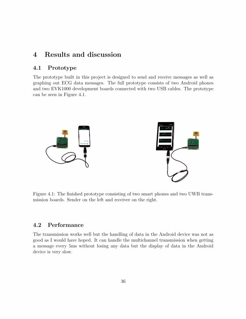
The prototype built in this project is designed to send and receive messages as well asgraphing out ECG data messages. The full prototype consists of two Android phonesand two EVK1000 development boards connected with two USB cables. The prototypecan be seen in Figure 4.1.
Figure 4.1: The finished prototype consisting of two smart phones and two UWB trans-mission boards. Sender on the left and receiver on the right.
4.2 Performance
The transmission works well but the handling of data in the Android device was not asgood as I would have hoped. It can handle the multichannel transmission when gettinga message every 5ms without losing any data but the display of data in the Androiddevice is very slow.
36

4.2.1 Data rate
Data rate (or data throughput) is the amount of data that can be continuously transferredbetween two devices without taking into account the time it takes when starting andending a transmission.
Each message has a payload of 48 bytes (4 bytes/channel over 12 channels) althoughthe number of bytes with headers is larger than that. We send with a rate of 200messages/s. Every 5ms as it is the maximum that the graphing application can handle.
This gives 9.6kB/s [Bytes/second] (48B*200) or 76.8kb/s [Bits/second] (48B*8*200).If we send just one data channel we get 4 Bytes/message and this can be handled evenat the maximum sending rate.
The theoretical maximum is 6.8 Mb/s if we use the non-standard format for sendingmessages without the MAC-header where each message can be 1023 Bytes long and wedon’t take the processing of messages into account. As we use the standard UWB frame of127 Bytes instead of 1023 we get a theoretical maximum throughput of 0.85 Mb/s. Thisis the limit for the EVK1000 cards. The USB 2.0 link protocol used between phonesand EVK1000 is 480Mb/s so the bottleneck of the system is firstly the processing ofmessages (76.8kb/s), then the sending via UWB (0.85 Mb/s) and lastly the sending ofUSB messages (480Mb/s). This can be seen in Figure 4.2.
Android Application
75kb/s
USB 480Mb/s
UWB 0.85Mb/s(6.8Mb/s)
USB 480Mb/s
Android Application
75kb/s
Figure 4.2: Overview of bottlenecks in system.
4.2.2 Latency
Latency is defined as the time it takes for one package to travel between devices. Devicesthat has a low latency are very good for sending data in irregular intervals. A devicethat has high latency does not necessarily have bad throughput as latency is the timeit takes to start the transmission, a delay in time. For this project the latency wasvery low. The transmission of a single package is sent without noticeable delay butthis varies with distance as with a larger distance the packages has to be retransmitted
37

multiple times. To avoid too large delay from the EVK1000 the maximum amount ofretransmissions have been limited to three. The EVK1000 will wait 2 µs between eachretransmission so the maximum delay from the EVK1000 is 6 µs. The handling timefor sending and receiving a package (containing the data of all channels) in the Androiddevices is approximately 2 ms. The delay from the EVK1000 can thus be neglected asthe handling time is much larger.
4.2.3 Energy consumption
I could not find any data of the energy consumption of the EVK1000 board but it requiresat least 250mA via 5V USB to function properly. The EVK1000 has to power LEDs, themicroprocessor and the LCD screen which consumes extra power. The DW1000 UWBtransceiver chip has a low power consumption and can enter sleep or deep sleep modeto conserve lots of energy during downtime. The currents shown in Table 4.1 gives theaverage current for the different operating states [1].
State TX RX IDLE Sleep Deep SleepCurrent 62 mA 125 mA 18 mA 1 µA 50 nA
Table 4.1: Energy consumption for DW1000 chip for different operating modes.
4.3 Android application
The android application has a couple of problems. The main one being that whiledisplaying the graphs it is very slow and CPU heavy. To work around this it would bepossible to try out other libraries or write your own to display the graphs.
4.4 Problems and solutions
Many hardware problems were encountered during the project, which slowed down theprogress of building a control system. Some of these problems were
• EVK1000 not being able to send/receive as expected.
The initial idea behind the project was to send data over several frequencies to maximizedata throughput for the available spectrum (3-7 GHz [1]). However, EVK1000 limits theuser to only send on one channel at a time, meaning that this cannot be parallelized by
38

using all channels simultaneously. Perhaps this will be available in future UWB chips.The idea was dropped and instead one channel is used.
• EVK1000 not having an ADC input soldered.
One idea was to simulate analog ECG signals as input for the EVK1000. This proved tobe difficult as the EVK1000 does not have a soldered pin to the built in analog-digitalconverter on the microprocessor. Soldering a pin onto the EVK1000 could have solvedthis problem but that was left as future work. Instead ECG signals were simulated inone smart phone and sent to the other.
4.5 Comparison of wide and narrow band communication
As of today (2018) the UWB protocol hasn’t been as developed and researched as narrowband communication (WiFi/Blutooth). In theory the use of UWB should be more energyefficient than both WiFi and bluetooth as sending information in pulses requires lessenergy than continuous waveforms. One article from 2016 mentions the use of UWBsending over three bands reaching data rates of 1 GB/s [22] while other applicationsuses data rates of 250 MB/s. The three bands take up a bandwidth of 1500 MHz. Themodule used in this project has a fairly low data rate but the DW1000 is mainly usedfor ranging application and not high data rate transmission.
When talking about Bluetooth communication there are three main protocols thatare currently in use. These are classic (v2.x) high speed (3.0) and low-energy (v5.0).The classic BT is getting outdated and is replaced with BT 5.0. The high speed versionof BT can support high data rates but it uses a network that uses the same structure asWiFi (802.11) where the BT part is used as a gateway to connect to WiFi. The BT 5.0gives a very large range but it can’t apply such high data rate.
WiFi has several versions of the classic 802.11 protocol. The most common rightnow is 802.11g or 802.11n which has speeds supporting up to 450 Mb/s or 54 Mb/s.There are also faster versions called 802.11ac wave2 which supports up to 1.73 Gb/s.
An article from 2014 describes and compares the specifications for some of thewireless protocols [23]. We can use this comparison between the different technologies tocompare energy efficiency. The data seen in Table 4.2 describes the different technologiespresented in the study with updated WiFi and UWB specifications from 2018 [22], [24].
When talking about power in radio technology we often talk about Watt (mW/µWor nW) or decibel (dB/dBm). This is because the power of a signal is easiest describedlike this. The intensity of the signal will vary depending on range and medium it travelsthrough but the sending power is often in the range of nW or µW. We express the powerin terms if dBm as the dB scale is logarithmic and to avoid having too large or too
39

small numbers we use dB instead of W. To calculate this we use the conversion given byEquation 3 and Equation 4. Where P is given in mW and dBm is milli decibel.
dBm = 10 ∗ log10(P/1mW ) (3)
P = 1mW ∗ 10(dBm/10) (4)
The calculated values of transmission (TX) power is presented in three comparative units,W, dBm and dBm/MHz. UWB is most often presented in dBm/MHz and to clarify thedifference in TX power the three conversions have been made. The conversion for UWBfrom dBm/Mhz to W and dBm is done for the three banded 1Gb/s previously mentionedand represents the maximum power allowed for such a device.
We can see from the table that UWB is much more efficient although WiFi hasa higher throughput and the different technologies have different usage areas. Blue-tooth is more suited for small appliances that doesn’t need too high data rate such asbattery-powered headphones, speakers and printers while WiFi is more directed to homenetworks. UWB can be a contender on both of these areas as it has a high throughputand low energy cost.
Name WiFi UWB Bluetooth
Protocol 802.11a/b/g/n/ac 802.15.4-2011 802.15.1 v3, v4, v5Max data rate 1.73/0.45 Gb/s 1Gb/s 24/1/2Mb/sFrequency 2.4 GHz, 5.1 GHz 3.1-10.6 GHz 2.4 GhzChannel bandwidth 22 MHz 0.5-7.5 GHz 1 MHzTX power dBm 15-20 dBm -9.5dBm(1.5GHz) 0 - 10 dBmTX power dBm/MHz 6.58 dBm/Mhz -41.3 dBm/MHz 10 dBm/MHzTX power W 30-100 mW 0.11mW(1.5GHz) 1-10 mWRange 0-100 m 0-100 m 0-100 m/0-400m
Table 4.2: Comparison of the three main sending protocols
40
5 Conclusion and future work
We can conclude from this project that it is possible to use two EVK1000 as a way oftransmitting ECG signals and that the bottleneck of the system is the graphical handlingof messages. UWB is an excellent method of sending information over short distanceseven though it’s not as developed as Bluetooth or Wifi. I believe that UWB will playa much larger role in the future for short range data heavy transmission like real timewireless streaming.
Improvements of the system would be to firstly take care of the problem with thegraphing, making it faster. One could also program the EVK1000 to send messages ina faster pace and let the ACK waiting time be longer, the problem with that is thatthe device cannot send and wait for receiving messages at the same time so this has tobe timed in a better way, perhaps by sending 255 messages, then wait for ACKs for allof them and then see which messages needs to be retransmitted. This would lower theoverhead of each message as the sender doesn’t have to switch over to listening modeafter each message sent and the transmitter doesn’t have to switch to sending mode foreach message.
For future work a proper ECG instead of the simulated data could be attached tothe prototype. This would be done by either attaching, to the system, a full ECG system(nodes, amplifier and analog-to-digital converter) that outputs an digital signal signalor just the nodes and amplifier. The problem here is that the EVK1000 does not havesoldered pins available for analog to digital conversion. The ARM processor supportsthis but the development board does not.
The specifications for the project was to design a system to transmit 12 channels ofdata. The original idea had to be scrapped due to hardware limitations but in the enda working prototype that sends 12 channels of data from one Android device to anotherwas successfully constructed.
Over all many new things have been learned during this project, the most importantbeing how important it is to plan out your work and to do your research properly. Thehardware limitations were discovered after the start of the project and I had to makedo with the hardware available. I also got lots of experience with Android applicationdevelopment and ARM programming during the project.
The most time consuming part of this project was to research the program on theEVK1000, called DecaRanging and to deduce how that worked. In the end that wasscrapped and I deployed my own version of the program with some changed functionsand a new main method for the cards that only handled data transmission and notranging. Writing the android application took a lot of time as I had no prior experience
41

in application coding.If we were to remake this project I would have researched more into similar project
before diving head first into the project. Over all the project was a success and theproject fulfilled the description and question set up at the start of the project.
42

References
[1] Decawave Ltd., “DW1000 Data sheet version 2.13,” 2017.
[2] Federal Communications Commission, “Revision of part 15 of the commission’s rulesregarding UWB Transmission systems,” Apr. 2002.
[3] K. Siwiak and D. McKeown, “Ultra-wideband radio technology,” John Wiley andSons, Ltd, 2004.
[4] Decawave ltd., “UWB Regulations, A summary of worldwide telecommunicationsregulations governing the use of ultra wideband,” Apr. 2015.
[5] A. Goldsmith, “Wireless communications,” Cambridge university, pp. 461–464,2013. [Online]. Available: http://dx.doi.org/10.1109/35.267438
[6] International telecommunication union, “Data networks and open system commu-nications ITU-T recommendation X.200,” 1994.
[7] IEEE Computer Society, “IEEE Standard for Local and metropolitan area networks-Part 15.4: Low-Rate Wireless Personal Area Networks(LR-WPANs),” IEEE Std802.15.4-2011, 2011.
[8] GSM arena, “GSMarena Samsung Galaxy S5,” Mar. 2018. [Online]. Available:https://www.gsmarena.com/samsung galaxy s5-6033.php
[9] ——, “GSMarena Asus Zenpad C7.0 Z170MG,” Mar. 2018. [Online]. Available:https://www.gsmarena.com/asus zenpad c 7 0 z170mg-7364.php
[10] Samsung, “Galaxy s5 16gb,” May 2017. [On-line]. Available: https://www.samsung.com/us/mobile/phones/galaxy-s/samsung-galaxy-s5-verizon-shimmery-white-sm-g900vzwavzw/
[11] Asus, “Asus zenpad c 7.0,” May 2017. [Online]. Available: https://dlcdnimgs.asus.com/websites/global/products/j6NVqIO5IONwrloP/v3/design/imgs/ultimate.png
[12] Decawave Ltd., “Decawave EVK1000 product brief,” 2017.
[13] Pozyx labs, “Pozyx, accurate positioning,” Jan. 2018. [Online]. Available:https://www.pozyx.io/
[14] STMicroelectronics Corp., “STM32F105xx, STMF107xx Data sheet,” 2009.
43

[15] Google Inc., “Android studio 3.0.1,” Jan. 2018. [Online]. Available: https://developer.android.com/studio/index.html
[16] Massachusetts Institute of Technology, “MIT License,” Jan. 2018. [Online].Available: https://opensource.org/licenses/MIT
[17] Apache Software Foundation, “Apache License, Version 2.0,” Jan. 2018. [Online].Available: https://www.apache.org/licenses/LICENSE-2.0
[18] CoIDE, “CooCox COIDE 2.0,” Jan. 2018. [Online]. Available: www.coocox.org
[19] Mathworks Inc., “Matlab 2017,” Jan. 2018. [Online]. Available: https://se.mathworks.com/products/matlab.html
[20] K. Raviprakash, “ECG Simulation using MATLAB v1.0,” Jan. 2018.[Online]. Available: https://se.mathworks.com/matlabcentral/fileexchange/10858-ecg-simulation-using-matlab
[21] A. Gawerth, “Embedded wireless communication: Connectivity of a smartphonewith bluetoothle and uwb devices,” Uppsala University, 2017.
[22] N.-S. Kim and J. M. Rabaey, “A high data-rate energy-efficient triple-channel uwb-based cognitive radio,” IEEE Journal of Solid-State Circuits, vol. 51, no. 4, pp.809–820, 2016.
[23] K. Pothuganti and A. Chitneni, “A comparative study of wireless protocols: Blue-tooth, uwb, zigbee, and wi-fi,” Advance in Electronic and Electric Engineering,vol. 4, no. 6, pp. 655–662, 2014.
[24] Intel, “St-link v2 programmer,” Dec. 2017. [Online]. Avail-able: https://www.intel.com/content/www/us/en/support/articles/000005725/network-and-i-o/wireless-networking.html
44