Wired M-Bus Water Meters flowIQ® 2101/3100 · TECHNICAL DESCRIPTION Wired M-Bus • Water Meters...
30
Technical Description Wired M-Bus Water Meters flowIQ® 2101/3100
Transcript of Wired M-Bus Water Meters flowIQ® 2101/3100 · TECHNICAL DESCRIPTION Wired M-Bus • Water Meters...

Technical Description
Wired M-Bus Water Meters flowIQ® 2101/3100

TECHNICAL DESCRIPTION Wired M-Bus • Water Meters flowIQ® 2101/3100
2 Kamstrup A/S · Technical Description · 55121944_A1_GB_08.2016
Contents 1 Introduction........................................................................................................................................................... 4
1.1 M-Bus ............................................................................................................................................................ 4
1.2 M-Bus communication .................................................................................................................................. 4
2 M-Bus water meter flowIQ® 2101/3100 ................................................................................................................ 4 2.1 Physical properties ........................................................................................................................................ 5
3 Design .................................................................................................................................................................... 5 3.1 Applications................................................................................................................................................... 5
3.1.1 Analysis ................................................................................................................................................. 5
3.1.2 Billing ..................................................................................................................................................... 5
3.1.3 Emulation .............................................................................................................................................. 5
3.1.4 Controlling and regulating ..................................................................................................................... 5
4 Installation ............................................................................................................................................................. 5
5 Data communication ............................................................................................................................................. 6 5.1 Bus communication ...................................................................................................................................... 6
5.2 Communication interval ................................................................................................................................ 6
5.3 Addressing forms .......................................................................................................................................... 6
5.3.1 Primary addressing ................................................................................................................................ 7
5.3.2 Secondary addressing ........................................................................................................................... 8
5.3.3 Enhanced secondary addressing ........................................................................................................... 9
5.3.4 Wildcard search with break detection ................................................................................................ 10
5.4 M-Bus formats ............................................................................................................................................ 10
5.5 M-Bus master to M-Bus water meter ......................................................................................................... 12
5.6 M-Bus slave to M-Bus master ..................................................................................................................... 13
5.6.1 REQ_UD2 -> RSP_UD ........................................................................................................................... 13
5.6.2 REQ_UD1 -> ACK ................................................................................................................................. 14
5.6.3 REQ_SKE -> RSP_SKE .......................................................................................................................... 14
5.7 Information codes ....................................................................................................................................... 14
5.7.1 Status field .......................................................................................................................................... 15
5.7.2 Temporary error.................................................................................................................................. 15
5.8 Datagram .................................................................................................................................................... 16
6 Reading loggers from flowIQ® 2101/3100 wired M-Bus....................................................................................... 17
7 Configuration of meter via the M-Bus network .................................................................................................... 17 7.1 Setting Primary M-Bus address ................................................................................................................... 18
7.2 Setting Date and time ................................................................................................................................. 19

Wired M-Bus • Water Meters flowIQ® 2101/3100 TECHNICAL DESCRIPTION
Kamstrup A/S · Technical Description · 55121944_A1_GB_08.2016 3
7.3 Application select/reset .............................................................................................................................. 19
8 Protocol ............................................................................................................................................................... 20 8.1 RSP_UD data flowIQ® 2101/3100 data using Kamstrup specified VIFE....................................................... 20
8.2 RSP_SKE response from flowIQ® 2101/3100 .............................................................................................. 25
8.3 Data header in RSP_UD ............................................................................................................................... 26
8.4 DIF (Data Information Field) ........................................................................................................................ 27
8.5 Primary VIF (Value Information Field) ......................................................................................................... 28
8.6 Special purpose VIF ..................................................................................................................................... 29
8.7 Main VIFE-code extension ........................................................................................................................... 29
TECHNICAL DESCRIPTION Wired M-Bus • Water Meters flowIQ® 2101/3100
4 Kamstrup A/S · Technical Description · 55121944_A1_GB_08.2016
1 Introduction
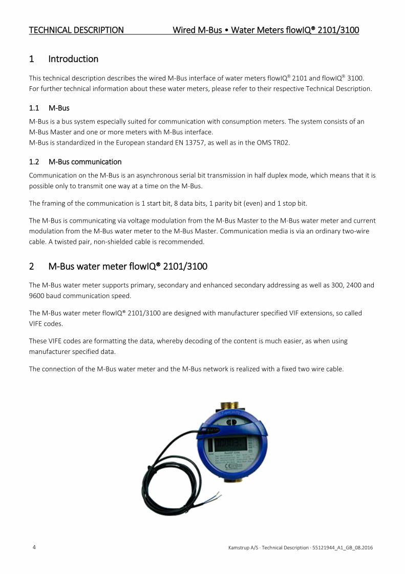
This technical description describes the wired M-Bus interface of water meters flowIQ 2101 and flowIQ 3100. For further technical information about these water meters, please refer to their respective Technical Description.
1.1 M-Bus
M-Bus is a bus system especially suited for communication with consumption meters. The system consists of an M-Bus Master and one or more meters with M-Bus interface. M-Bus is standardized in the European standard EN 13757, as well as in the OMS TR02.
1.2 M-Bus communication
Communication on the M-Bus is an asynchronous serial bit transmission in half duplex mode, which means that it is possible only to transmit one way at a time on the M-Bus.
The framing of the communication is 1 start bit, 8 data bits, 1 parity bit (even) and 1 stop bit.
The M-Bus is communicating via voltage modulation from the M-Bus Master to the M-Bus water meter and current modulation from the M-Bus water meter to the M-Bus Master. Communication media is via an ordinary two-wire cable. A twisted pair, non-shielded cable is recommended.
2 M-Bus water meter flowIQ® 2101/3100
The M-Bus water meter supports primary, secondary and enhanced secondary addressing as well as 300, 2400 and 9600 baud communication speed.
The M-Bus water meter flowIQ® 2101/3100 are designed with manufacturer specified VIF extensions, so called VIFE codes.
These VIFE codes are formatting the data, whereby decoding of the content is much easier, as when using manufacturer specified data.
The connection of the M-Bus water meter and the M-Bus network is realized with a fixed two wire cable.

Wired M-Bus • Water Meters flowIQ® 2101/3100 TECHNICAL DESCRIPTION
Kamstrup A/S · Technical Description · 55121944_A1_GB_08.2016 5
2.1 Physical properties
The M-Bus interface is integrated in the flowIQ® 2101/3100.
The bus is polarity independent.
The M-Bus water meter have a max power consumption of 1 unit load (1.5 mA) drawn from the M-Bus Master.
Rin: 440 Ohm
Cin: 0.5nF
Bus current and voltages according to EN 13757-2.
3 Design
The M-Bus water meters fulfil the requirements in the M-Bus standard EN 13757:2013 as well as the OMS TR02:2015 and can be used in a wide variety of applications using M-Bus protocol.
3.1 Applications
The M-Bus water meters are designed with focus on high flexibility to fulfill a wide pallet of existing and future applications.
3.1.1 Analysis
The flowIQ® 2101/3100 support high quantities of data and all relevant data for analysis can be read out. This is valid for both actual meter data as well as for target data.
3.1.2 Billing
All relevant data for billing purposes can be read out from the flowIQ® 2101/3100.
3.1.3 Emulation
The wired M-Bus datagram in flowIQ® 2101/3100 is fixed and cannot be altered
3.1.4 Controlling and regulating
The water meter can deliver online data in intervals down to 15 seconds (however at reduced battery lifetime) for controlling and regulating purposes with a high communication speed.
4 Installation
As M-Bus is polarity independent there is no + and ÷ to care about.
Configuring the primary address can be done with METERTOOL HCW using an optical readout head or via the M-Bus network. It is recommended that the entire M-Bus system is not powered up during installation of new M-Bus water meters.

TECHNICAL DESCRIPTION Wired M-Bus • Water Meters flowIQ® 2101/3100
6 Kamstrup A/S · Technical Description · 55121944_A1_GB_08.2016
5 Data communication
5.1 Bus communication
The M-Bus water meter design is based on the newest technology, offering high-speed communication as well as very frequent reading interval.
The transmission speed is automatically detected by the M-Bus water meter. When the M-Bus water meter receives a message from the M-Bus Master on a certain speed, it will reply with the same speed.
The M-Bus water meters flowIQ® 2101/3100 supports 300, 2400 and 9600 baud communication speed.
5.2 Communication interval
In order to maintain the full 16 years battery lifetime of the water meter, the read out interval shall be longer than 1 minute. Since the most frequent integration interval in the flowIQ® 2101/3100 is 32 seconds, a more frequent reading is not recommended. A more frequent reading interval than 32 seconds will provide redundant information.
5.3 Addressing forms
To make the M-Bus system operate with more M-Bus water meters connected, it is necessary to distinguish between the individual M-Bus water meter. This is done by means of following M-Bus ID numbers in each M-Bus meter:
• Primary address: 001...250, and the special addresses 0, 253, 254 and 255 • M-Bus ID number: 8 digits 00000000… 99999999 • Manufacturer ID: Always 2D2Ch for ’KAM‘ for Kamstrup M-Bus water meter • Version ID flowIQ® 2101 1Fh • Version ID flowIQ® 3100 1Dh • Device type ID: 06h = Volume warm, 16h = Volume cold • Fabrication number: Serial number, 8 digits 0000000… 99999999
When the M-Bus Master sends a message on the M-Bus, some or all of the above ID numbers on the M-Bus water meters are encoded in the message. Thus, only the M-Bus water meter with the addressed ID numbers will reply.
Manufacturer ID, Version ID and Fabrication number are permanently encoded into the M-Bus water meter and cannot be changed.
Wired M-Bus • Water Meters flowIQ® 2101/3100 TECHNICAL DESCRIPTION
Kamstrup A/S · Technical Description · 55121944_A1_GB_08.2016 7
5.3.1 Primary addressing
A valid primary M-Bus address has a value between 000 and 250.
The primary M-Bus address is either configured specific in the flowIQ® 2101/3100 or the last digits of the meter number are used.
As factory default, the primary address in flowIQ® 2101/3100 equals to the last 3 digits of the meter number. If the last 3 digits are larger than 250 (e.g. 345) the first digit is ignored and the M-Bus water meter address is only determined by the last 2 digits (e.g. 45).
During the ordering process specific primary addresses can be specified.
Changing the primary address can be performed in following ways:
• Programming with METERTOOL HCW, via Optical Readout Head • Remotely, via M-Bus master
In connection with primary addressing of the M-Bus, two or more M-Bus water meters on the same M-Bus system cannot have the same primary address. However, in connection with secondary addressing or enhanced secondary addressing it is possible to distinguish M-Bus water meters with the same primary address on the same M-Bus.
Standard address range for an M-Bus water meter is 001... 250.
In addition to this, there are 4 special addresses that work as follows:
Adr. 000: Ordinary primary address reserved for non-configured M-Bus water meter.
Adr. 253: Used for secondary addressing. Only M-Bus water meters selected by (enhanced) secondary addressing will reply.
Adr. 254: All M-Bus meters will reply to this address. The address can only be used in systems where only 1 M-Bus water meter is connected.
Adr. 255: No M-Bus meter will reply to this address, but all will receive the message. This address makes it possible e.g. to change the baud rate, on an entire system at the same time, by sending only one telegram.

TECHNICAL DESCRIPTION Wired M-Bus • Water Meters flowIQ® 2101/3100
8 Kamstrup A/S · Technical Description · 55121944_A1_GB_08.2016
5.3.2 Secondary addressing
A valid secondary M-Bus address has a value between 00000000 and 99999999 and is in the flowIQ® 2101/3100 identical to the unique serial number.
In connection with secondary addressing, the M-Bus water meters are selected via the primary address 253 with its 8 byte long complete M-Bus ID consisting of:
• M-Bus ID number. Default from Kamstrup: The last 8 digits in the meter number / customer number (4 bytes) • Manufacturer ID = ASCII characters ‘KAM’ for Kamstrup encoded to the value 2D2Ch (2 bytes) • Version/generation ID number for MULTICAL® 21 = 34h (1 byte) • Device type ID (1 byte)
These 8 bytes make up the secondary address of the M-Bus water meter. It is possible to replace the individual bytes with wildcard characters. See chapter 5.3.4 for further information.
Selection of M-Bus water meter via secondary address (and deselecting other M-Bus water meter):
Start character 68h L-field 0Bh L-field 0Bh Start character 68h C-field 53h or 73h A-field FDh CI-field 52h ID No. LSB 37 or FF BCD E.g. M-Bus ID number = 4118737 ID No. 87 or FF BCD ID No. 11 or FF BCD ID No. MSB 04 or FF BCD Man. ID LSB 2Dh or FFh KAM encoded to 2D2Ch Man. ID MSB 2Ch or FFh Version ID flowIQ 2101
1Dh
Version ID flowIQ 2101
1Fh
Device ID 04h, 07h, 0Ah, 0Bh, 0Ch, or 0Dh (see also ID numbers) or FFh Checksum Xxh Stop character 16h
As long as the M-Bus water meter is selected, it will reply to primary address 253, which is dedicated to secondary addressing. The M-Bus water meter is deselected either by
• sending a new selection via primary address 253 with a secondary address – different from the one of the M-Bus water meter (by means of which another M-Bus meter may be selected, if necessary) or
• sending normalization (SND_NKE) to primary address 253.

Wired M-Bus • Water Meters flowIQ® 2101/3100 TECHNICAL DESCRIPTION
Kamstrup A/S · Technical Description · 55121944_A1_GB_08.2016 9
5.3.3 Enhanced secondary addressing
A valid secondary M-Bus address has a value between (M-Bus ID No. 00000000-99999999) / (M-Bus fabrication No. 00000000-99999999) and is, in the flowIQ® 2101/3100, identical to the unique serial number.
The M-Bus water meter secondary address can therefore be extended in order to comprise the 8 digit BCD ‘fabrication number’ (4 bytes) – identical with the serial number of the meter. This number is unique for each flowIQ® 2101/3100 and cannot be changed after the meter has been produced.
In connection with enhanced secondary addressing, the M-Bus water meter is selected by adding ‘fabrication number’ as an ordinary data record with DIF = 0Ch (for 4 bytes, 8 digit BCD) and VIF = 78h (for fabrication number) in the selection telegram after the secondary address.
When a M-Bus water meter is selected via enhanced secondary address, it will reply to primary address 253, as it is with the ordinary secondary addressing. The M-Bus water meter is deselected either by
• sending a new selection via primary address 253 with an enhanced or ordinary secondary address – different from the one from the M-Bus water meter (by means of which another M-Bus meter may be selected, if necessary) or
• sending a normalization (SND_NKE) to primary address 253.
Selection of M-Bus water meter via enhanced secondary address (and deselecting other M-Bus water meter):
Start character 68h L-field 11h L-field 11h Start character 68h C-field 53h or 73h A-field FDh CI-field 52h ID No. LSB 37 or FF BCD E.g. M-Bus ID number = 4118737 ID No. 87 or FF BCD ID No. 11 or FF BCD ID No. MSB 04 or FF BCD Man. ID LSB 2Dh or FFh KAM encoded to 2D2Ch Man. ID MSB 2Ch or FFh Version ID flowIQ2101
1Fh
Version ID flowIQ 3100
1Dh
Device ID 16 (cold water), 06 (warm water) Record 0Ch DIF: 4 bytes, 8 digit BCD Fabrication. no. 78h VIF: Fabrication no. (serial no.),
e.g.: 2500176 Fabr. no. LSB 76 or FF BCD Fabr. no. 01 or FF BCD Fabr. no. 50 or FF BCD Fabr. no. MSB 02 or FF BCD Checksum Xxh Stop character 16h

TECHNICAL DESCRIPTION Wired M-Bus • Water Meters flowIQ® 2101/3100
10 Kamstrup A/S · Technical Description · 55121944_A1_GB_08.2016
5.3.4 Wildcard search with break detection
The M-Bus water meter supports wild card search for an easy search for connected meters. Some or all digits of the meters secondary and/or enhanced secondary addresses can be replaced with wild cards when searching for meters in an M-Bus network. The integrated break detection functionality eases the meter search on the M-Bus network.
The M-Bus water meter will not compare the wildcard characters with the equivalent digits in “its own” secondary and enhanced secondary address, and the M-Bus water meter will be selected if the other characters match.
The 8 digits in the M-Bus ID number and the 8 digits in the ‘fabrication number‘ (= serial number) can each be replaced by the wildcard character Fh.
The binary values ‘Manufacturer ID’ (2 bytes), ‘Version / generation ID’ (1 byte), and ‘Device type ID’ (1 byte) in the secondary address may be replaced by the wildcard byte value FFh.
The values for DIF = 0Ch (for 4 bytes, 8 digit BCD) and VIF = 78h (for fabrication number) in connection with enhanced secondary addressing cannot be replaced by wildcard values.
By means of wildcard characters (BCD Fh) and values (binary FFh), an M-Bus Master can, relatively quickly, search the M-Bus for connected M-Bus water meters, without knowing the M-Bus water meters primary, secondary or enhanced secondary addresses in advance.
5.4 M-Bus formats
The M-Bus protocol comprises following telegram / message format types:
Single character Short frame Control frame Long frame Ack. = E5h Start = 10h Start = 68h Start = 68h C-Field L-Field = 3 L-Field = N + 3 A-Field L-Field = 3 L-Field = N + 3 Checksum Start = 68h Start = 68h Stop = 16h C-Field C-Field A-Field A-Field CI-Field CI-Field Checksum Userdata Stop = 16h (N = 0..252 bytes) Checksum Stop = 16h
The meaning of the C-Field C-FIELD: 40h SND_NKE 08h RSP_UD 0Bh RSP_SKE 49h REQ_SKE 53h SND_UD (FCB=0) 73h SND_UD (FCB =1) 5Ah REQ_UD1 (FCB=0) 7Ah REQ_UD1 (FCB =1) 5Bh REQ_UD2 (FCB=0) 7Bh REQ_UD2 (FCB =1) 43h SND_UD2
Note: In the default application the FCB bit is not used and the M-Bus water meter accepts both FCB = 0 and FCB = 1.

Wired M-Bus • Water Meters flowIQ® 2101/3100 TECHNICAL DESCRIPTION
Kamstrup A/S · Technical Description · 55121944_A1_GB_08.2016 11
The meaning of the A-Field A-FIELD: xxh The primary address of the M-Bus water meter. FDh (253) The primary address of the M-Bus water meter in connection with secondary addressing.
However, in connection with RSP¬_UD the M-Bus water meter still replies with its own primary address.
FEh (254) Address to which all M-Bus water meters will reply. By using this address only one M-Bus water meter can be connected. The M-Bus water meter still replies with its own primary address.
(255) Joint address where all M-Bus water meters can receive data from the M-Bus Master, but replies are not returned.
The meaning of the CI-Field CI-FIELD: 50h Application select/reset. Select is used for logger reading applications. A reset will select the default
application. 51h Normal transmission of SND_UD, data send (M-Bus Master to M-Bus water meter). 52h Opening for secondary addressing (selection of M-Bus water meter) is required. 72h Respond in variable structure. B8h Baud rate shift to 300 baud. BBh Baud rate shift to 2400 baud. BDh Baud rate shift to 9600 baud. BEh Baud rate shift to 19200 baud. 72h Long 12 bytes APL header in RSP_UD response from device 7Ah Short 4 bytes APL header in RSP_UD response from device 78h No APL header in RSP_UD response from device A0h Kamstrup specific from master to slave A1h Kamstrup specific from slave to master
Note: As the flowIQ® 2101/3100 M-Bus water meters supports auto baud rate detection, it is not necessary to instruct them with a specific baud rate.

TECHNICAL DESCRIPTION Wired M-Bus • Water Meters flowIQ® 2101/3100
12 Kamstrup A/S · Technical Description · 55121944_A1_GB_08.2016
5.5 M-Bus master to M-Bus water meter
Communication on the M-Bus is initiated by the M-Bus Master. After this the addressed M-Bus water meter replies. Basically, there are 2 different communication sequences (from M-Bus Master to M-Bus water meter):
SEND -> CONFIRM REQUEST -> RESPONSE
When using ‘SEND -> CONFIRM’ the M-Bus Master sends a command or data to the M-Bus water meter, that replies with an acknowledgement (ACK). The acknowledgement (ACK) just means that the M-Bus water meter has received the telegram successfully, but it has not necessarily accepted the contents.
When using ‘REQUEST -> RESPONSE’ the M-Bus Master sends a request to the M-Bus water meter, which in return replies with a datagram according to the request.
The M-Bus water meter only supports ‘Mode 1’ data format where all multi-byte data values to and from the M-Bus water meter are transmitted with Least Significant Byte (LSB) first.
In the default application the FCB / FCV bit in the C-field is not used and the M-Bus water meter accepts both FCB = 0 and FCB = 1.
The M-Bus water meter does not use DFC (Data Flow Control) / ACD (Access Demand) bits, which means that both bits will always have the value 0 in the C-Field from the M-Bus water meter.
The following describes the individual M-Bus telegrams, from M-Bus Master to M-Bus water meter and from M-Bus water meter to M-Bus Master, that are supported.
REQ_UD1: Short frame. Request for time-critical data alarm. Start character 10h C-field 5Ah or 7A A-field xxh or FDh Checksum Xxh Stop character 16h
REQ_UD2: Short frame. Request for data from the M-Bus interface. Start character 10h C-field 5Bh or 7B A-field xxh or FDh Checksum xxh Stop character 16h
REQ_SKE: Short frame. Status request. Start character 10h C-field 49h A-field xxh or FDh Checksum xxh Stop character 16h

Wired M-Bus • Water Meters flowIQ® 2101/3100 TECHNICAL DESCRIPTION
Kamstrup A/S · Technical Description · 55121944_A1_GB_08.2016 13
SND_NKE: Short frame. Normalizes the M-Bus water meter. Start character 10h C-field 40h A-field xxh or FDh Checksum xxh Stop character 16h
SND_UD: Long frame, Data to the M-Bus water meter.
Start character 68h L-field xxh length field = number of data bytes N + 3 L-field xxh length field repeated Start character 68h C-field 53h (FCB=0) or 73h (FCB=1) = SND_UD A-field xxh or FDh CI-field xxh 51h = data send, 52h = secondary address
selection Data byte 1 xx : : : : Data byte 1 xx Checksum xxh Stop character 16h
5.6 M-Bus slave to M-Bus master
RSP_UD: Long frame. Data to M-Bus Master. See telegram later.
RSP_SKE: Short frame. Data to M-Bus Master. See telegram later.
ACK: Single control character. Data format from M-Bus Master received successfully.
Description of the codes of the individual formats can be viewed later in this document.
Communication takes place in following sequences:
5.6.1 REQ_UD2 -> RSP_UD
To collect meter data, from the M-Bus water meter, an REQ_UD2 is transmitted from the M-Bus Master. The M-Bus water meter checks the message, and if it is correct, the M-Bus water meter returns with an RSP_UD, which is meter data packed according to the M-Bus format for RSP_UD.
An example of a RSP_UD datagram can be viewed later in the manual.

TECHNICAL DESCRIPTION Wired M-Bus • Water Meters flowIQ® 2101/3100
14 Kamstrup A/S · Technical Description · 55121944_A1_GB_08.2016
5.6.2 REQ_UD1 -> ACK
REQ_UD1 from the M-Bus Master is a request for time-critical (alarm) data from the M-Bus water meter. The flowIQ® 2101/3100 M-Bus water meter does not support time-critical data (alarm protocol), but it replies with an ACK (link layer receipt) when receiving REQ_UD1, which means that the M-Bus water meter does not have any time-critical (alarm) data to transmit.
In this way, the M-Bus water meter will function in M-Bus systems with other M-Bus interface supporting time-critical data (alarm protocol).
5.6.3 REQ_SKE -> RSP_SKE
REQ_SKE from the M-Bus Master is a request for communication status and for information on whether the M-Bus water meter has any time-critical (alarm) data to send. When receiving an REQ_SKE the M-Bus water meter replies with an RSP_SKE, but as the M-Bus water meter does not support time-critical data (alarm protocol), and cannot have overflow in its input buffer, the status bits ACD (Access Demand) and DFC (Data Flow Control) will always be = 0 in the M-Bus water meter reply, which means that the M-Bus water meter does not have any time-critical (alarm) data to send and has no buffer overflow.
Therefore, the M-Bus water meter will function in M-Bus systems with other M-Bus interface supporting time-critical data (alarm protocol) and using communication status bit.
SND_NKE -> ACK
The M-Bus Master normalizes the M-Bus water meter with an SND_NKE and the M-Bus water meter acknowledges successful receipt of the message by means of an ACK. An SND_NKE to primary address 253 will deselect the M-Bus water meter, if it was selected by means of secondary or enhanced secondary addressing.
SND_UD -> ACK
The M-Bus Master wishes to send data to the M-Bus water meter, or to select/deselect the M-Bus water meter via secondary or enhanced secondary addressing. The M-Bus water meter acknowledges successful receipt of the SND_UD telegram by means of an ACK. The acknowledgement (ACK) just means that the M-Bus water meter has received the telegram successfully in the Data Link Layer and is as such no guarantee that the M-Bus water meter has accepted the contents of the Application Layer.
Therefore, when receiving an SND_UD command with a new baud rate, the M-Bus water meter will acknowledge receipt by means of an ACK, even though it ignores the contents, as the M-Bus water meter automatically detects the baud rate on receipt.
5.7 Information codes
flowIQ® 2101/3100 indicates in the display, and in the wired M-Bus datagram, if a special state in the meter, called info codes, are present:
DRY: Meaning that the meter is not water filled, in this case nothing is measured.
REVERSE: Meaning that the water is flowing in the wrong direction in the meter.
LEAK: Meaning that the water has been running for more than 24 hours.
BURST: Meaning that the water flow is constantly high for more than 30 minutes.

Wired M-Bus • Water Meters flowIQ® 2101/3100 TECHNICAL DESCRIPTION
Kamstrup A/S · Technical Description · 55121944_A1_GB_08.2016 15
TAMPER: Meaning that the meter has been disassembled in an attempt of fraud.
The info code will disappear from the display and from the wired M-Bus datagram, when the condition that initiated it disappears. Info codes initiate the Temporary error (bit 4) in the status field.
5.7.1 Status field
flowIQ® 2101/3100 info codes are mapped to the error bit ‘Temporary error’ (bit 4) when any info code is active. Further, the ‘Power Low’ (bit 2) in the status field is set, when battery power is low.
The ‘Status field’ in the M-Bus data header can have one of the following values, or the sum of more values:
Status field value Description 00h No info code 04h Power Low on battery 10h Temporary Error 14h Power Low and Temporary Error
5.7.2 Temporary error
Temporary Error (Bit 4) is set when one of the info codes is active in flowIQ® 2101/3100.

TECHNICAL DESCRIPTION Wired M-Bus • Water Meters flowIQ® 2101/3100
16 Kamstrup A/S · Technical Description · 55121944_A1_GB_08.2016
5.8 Datagram
The datagram in flowIQ® 2101/3100 M-Bus water meter has a fixed data content.
Previously, Kamstrup has placed a number of special registers like configuration values in the manufacturer specified part of the telegram. This has required quite extensive knowledge of the meter in order to decode and format these data correct.
In order to be able to decode special data registers in an easier way, Kamstrup has taken the approach to define a number of manufacturer VIF extensions – so called VIFE. The outcome is that most reading systems can show the special registers in clear reading.
Below an example showing manufacturer specified data vs. Manufacturer specified VIFE:
Manufacturer specified data Special 10 00 00 00 5B C9 A5 02 48 EE 00 00 E0 B2 03 00 0001x 66 19 6D 00 00 00 00 00 C1 00 01 07 08 70 01 06 0002x 00 00 00 00 00
Manufacturer specified VIFE INT8 1234565000344 Inst Manufacturer specific ->0F INT4 34000 Inst Manufacturer specific ->11 INT4 13301000 Inst Manufacturer specific ->12 INT2 6145 Inst Manufacturer specific ->1A

Wired M-Bus • Water Meters flowIQ® 2101/3100 TECHNICAL DESCRIPTION
Kamstrup A/S · Technical Description · 55121944_A1_GB_08.2016 17
The datagram is fixed and cannot be changed. The datagram from flowIQ® 3100 large meter versions differs slightly from the one in flowIQ® 2101, because these large meters do not measure the water temperature.
flowIQ® 2101 and flowIQ® 3100 1.6 and 2.5 and 4.0 m3/h M-Bus data header Actual data Monthly data Meter data M-Bus ID Manufacturer ID Version ID Device type Access counter Status (set if any info codes is active) Configuration (not used)
Water meter reading (volume) Volume reverse Hour counter Actual flow Actual water temperature Actual ambient temperature Min Flow Day1)
Max Flow Day1) Min water temp Day1) Avg. water temp Day1) Min ambient temp Day1) Max ambient temp Day1) Avg. ambient temp Day1) Date/Time
Monthly target meter reading Min Flow 1 Month Max Flow 1 Month Min water temp Month Avg. water temp Month Min Ambient temp Month Max Ambient temp Month Avg. Ambient temp Month Target date
Information codes Config number Meter Type (main / sub type) Meter SW Revision
flowIQ® 3100 Q3 = 6.3 m3/h and higher. M-Bus data header Actual data Monthly data Meter data M-Bus ID Manufacturer ID Version ID Device type Access counter Status (info codes) Configuration (not used)
Water meter reading (volume) Volume reverse Hour counter Actual flow Actual ambient temperature Min Flow Day1)
Max Flow Day1) Min ambient temp Day1) Max ambient temp Day1) Avg. ambient temp Day1) Date/Time
Monthly target meter reading Min Flow 1 Month Max Flow 1 Month Min Ambient temp Month Max Ambient temp Month Avg. Ambient temp Month Target date
Info Config number Meter Type (main / sub type) Meter SW Revision
1) The daily flow and temperatures are the actual daily minimum, average or maximum values logged from midnight until the present reading time.
6 Reading loggers from flowIQ® 2101/3100 wired M-Bus
The loggers in the flowIQ® 2101/3100 can only be read with an optical reading head, the optical eye in the meter and the program LogView.
7 Configuration of meter via the M-Bus network
Following parameters can be sent to the M-Bus water meter, in order to change the configuration of the flowIQ® 2101/3100: • Primary M-Bus address • Date and time
Selection of the M-Bus water meter via secondary address or enhanced secondary address, and application select/reset is obtained via SND_UD telegram from the M-Bus Master to the M-Bus water meter. Selection of device for secondary addressing is made by CI-field = 52h, and application select/reset by CI-field = 50h.

TECHNICAL DESCRIPTION Wired M-Bus • Water Meters flowIQ® 2101/3100
18 Kamstrup A/S · Technical Description · 55121944_A1_GB_08.2016
The M-Bus water meter will also reply with an acknowledgement (ACK) when receiving a set of baud rate telegrams (CI-field = B8h... BFh), but will ignore the contents, as the M-Bus interface is furnished with automatic baud rate detection.
The individual datagram for writing data in the M-Bus water meter are shown subsequently.
7.1 Setting Primary M-Bus address
A dedicated register in the flowIQ® 2101/3100 is used for storing the primary address. This register may be overwritten with a new M-Bus primary address using the datagram format below.
Start character 68h L-field 06h L-field 06h Start character 68h C-field 53h (FCB=0) or 73h (FCB=1) A-field xxh or FDh CI-field 51h Record 01h DIF: 1 byte, binary Address 7Ah VIF: Address Primary add. xxh XX = 01h... FAh. For primary address = 1... 250 Checksum xxh Stop character 16h
Note: During the ordering process the primary address for each meter can be specified. Normally it is the last 2-3 digits of the customer number.

Wired M-Bus • Water Meters flowIQ® 2101/3100 TECHNICAL DESCRIPTION
Kamstrup A/S · Technical Description · 55121944_A1_GB_08.2016 19
7.2 Setting Date and time
To synchronize the time in the meter towards a main application real time clock, the time and date may be sent to the flowIQ® 2101/3100 using the datagram format below.
To avoid disturbing the internal loggers, setting the time must be done in due time before or after an hour shift. Typically the date/time is set once each 24 hour.
Start character 68h L-field 09h L-field 09h Start character 68h C-field 53h (FCB=0) or 73h (FCB=1) A-field xxh or FDh CI-field 51h Record 04h DIF: 4 bytes, compound data type F Date and time 6Dh VIF: Date and time, e.g. 02-09-04 13:10 standard time, valid Date, time LSB 0Ah IV, 0, MI5, MI4, MI3, MI2, MI1, MI0 Date, time 2Dh SU, HY1, HY0, H4, H3, H2, H1, H0 Date, time 82h Y2, Y1, Y0, D4, D3, D2, D1, D0 Date, time MSB 09h Y6, Y5, Y4, Y3, M3, M2, M1, M0 Checksum Xxh Stop character 16h
As flowIQ® 2101/3100 uses two digits to indicate year (00... 99), the flowIQ® 2101/3100 M-Bus always sends information concerning year as 2000... 2099 (bit HY1:HY0 always = 01 in ‘Date and time record’, VIF = 6Dh and DIF = 04h, compound data type F).
Note: See EN13757-3 Annex A ‘Coding of data records’ for details on how to decode the Date/Time data type.
7.3 Application select/reset
In connection with application reset the flowIQ® 2101/3100 M-Bus water meter returns an ‘ACK’. Nothing further happens and nothing is reset.
TECHNICAL DESCRIPTION Wired M-Bus • Water Meters flowIQ® 2101/3100
20 Kamstrup A/S · Technical Description · 55121944_A1_GB_08.2016
8 Protocol
When using M-Bus Masters and/or reading software of another manufacturer, the same commands must be used. The flowIQ® 2101/3100 M-Bus water meter only support commands stated in this description.
The datagram is fixed.
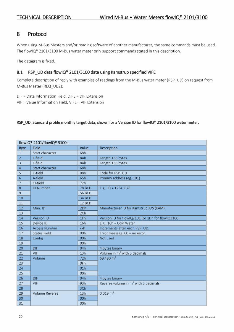
8.1 RSP_UD data flowIQ® 2101/3100 data using Kamstrup specified VIFE
Complete description of reply with examples of readings from the M-Bus water meter (RSP_UD) on request from M-Bus Master (REQ_UD2):
DIF = Data Information Field, DIFE = DIF Extension VIF = Value Information Field, VIFE = VIF Extension
RSP_UD: Standard profile monthly target data, shown for a Version ID for flowIQ® 2101/3100 water meter.
flowIQ® 2101/flowIQ® 3100: Byte Field Value Description 1 Start character 68h 2 L-field 8Ah Length 138 bytes 3 L-field 8Ah Length 138 bytes 4 Start character 68h 5 C-field 08h Code for RSP_UD 6 A-field 65h Primary address (eg. 101) 7 CI-field 72h 8 ID Number 78 BCD E.g.: ID = 12345678 9 56 BCD 10 34 BCD 11 12 BCD 12 Man. ID 2Dh Manufacturer ID for Kamstrup A/S (KAM) 13 2Ch 14 Version ID 1Fh Version ID for flowIQ2101 (or 1Dh for flowIQ3100) 15 Device ID 16h E.g.: 16h = Cold Water 16 Access Number xxh Increments after each RSP_UD. 17 Status Field 00h Error message. 00 = no error. 18 Config 00h Not used 19 00h 20 DIF 04h 4 bytes binary 21 VIF 13h Volume in m3 with 3 decimals 22 Volume 72h 69.490 m3 23 0Fh 24 01h 25 00h 26 DIF 04h 4 bytes binary 27 VIF 93h Reverse volume in m3 with 3 decimals 28 3Ch 29 Volume Reverse 13h 0.019 m3 30 00h 31 00h
Wired M-Bus • Water Meters flowIQ® 2101/3100 TECHNICAL DESCRIPTION
Kamstrup A/S · Technical Description · 55121944_A1_GB_08.2016 21
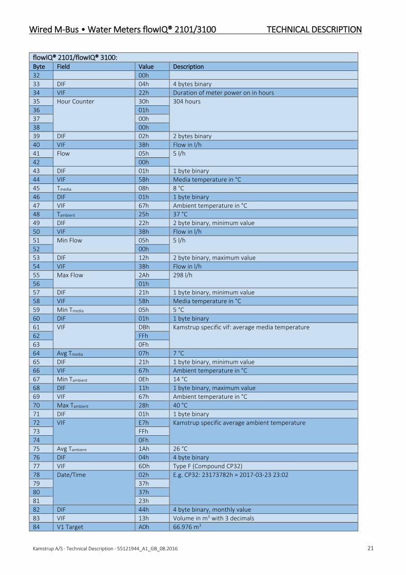
flowIQ® 2101/flowIQ® 3100: Byte Field Value Description 32 00h 33 DIF 04h 4 bytes binary 34 VIF 22h Duration of meter power on in hours 35 Hour Counter 30h 304 hours 36 01h 37 00h 38 00h 39 DIF 02h 2 bytes binary 40 VIF 3Bh Flow in l/h 41 Flow 05h 5 l/h 42 00h 43 DIF 01h 1 byte binary 44 VIF 5Bh Media temperature in °C 45 Tmedia 08h 8 °C 46 DIF 01h 1 byte binary 47 VIF 67h Ambient temperature in °C 48 Tambient 25h 37 °C 49 DIF 22h 2 byte binary, minimum value 50 VIF 3Bh Flow in l/h 51 Min Flow 05h 5 l/h 52 00h 53 DIF 12h 2 byte binary, maximum value 54 VIF 3Bh Flow in l/h 55 Max Flow 2Ah 298 l/h 56 01h 57 DIF 21h 1 byte binary, minimum value 58 VIF 5Bh Media temperature in °C 59 Min Tmedia 05h 5 °C 60 DIF 01h 1 byte binary 61 VIF DBh Kamstrup specific vif: average media temperature 62 FFh 63 0Fh 64 Avg Tmedia 07h 7 °C 65 DIF 21h 1 byte binary, minimum value 66 VIF 67h Ambient temperature in °C 67 Min Tambient 0Eh 14 °C 68 DIF 11h 1 byte binary, maximum value 69 VIF 67h Ambient temperature in °C 70 Max Tambient 28h 40 °C 71 DIF 01h 1 byte binary 72 VIF E7h Kamstrup specific average ambient temperature 73 FFh 74 0Fh 75 Avg Tambient 1Ah 26 °C 76 DIF 04h 4 byte binary 77 VIF 6Dh Type F (Compound CP32) 78 Date/Time 02h E.g. CP32: 23173782h = 2017-03-23 23:02 79 37h 80 37h 81 23h 82 DIF 44h 4 byte binary, monthly value 83 VIF 13h Volume in m3 with 3 decimals 84 V1 Target A0h 66.976 m3
TECHNICAL DESCRIPTION Wired M-Bus • Water Meters flowIQ® 2101/3100
22 Kamstrup A/S · Technical Description · 55121944_A1_GB_08.2016
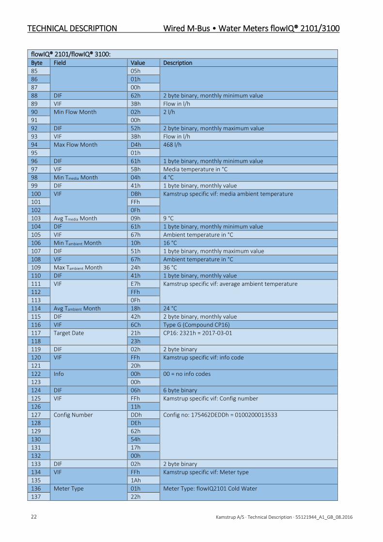
flowIQ® 2101/flowIQ® 3100: Byte Field Value Description 85 05h 86 01h 87 00h 88 DIF 62h 2 byte binary, monthly minimum value 89 VIF 3Bh Flow in l/h 90 Min Flow Month 02h 2 l/h 91 00h 92 DIF 52h 2 byte binary, monthly maximum value 93 VIF 3Bh Flow in l/h 94 Max Flow Month D4h 468 l/h 95 01h 96 DIF 61h 1 byte binary, monthly minimum value 97 VIF 5Bh Media temperature in °C 98 Min Tmedia Month 04h 4 °C 99 DIF 41h 1 byte binary, monthly value 100 VIF DBh Kamstrup specific vif: media ambient temperature 101 FFh 102 0Fh 103 Avg Tmedia Month 09h 9 °C 104 DIF 61h 1 byte binary, monthly minimum value 105 VIF 67h Ambient temperature in °C 106 Min Tambient Month 10h 16 °C 107 DIF 51h 1 byte binary, monthly maximum value 108 VIF 67h Ambient temperature in °C 109 Max Tambient Month 24h 36 °C 110 DIF 41h 1 byte binary, monthly value 111 VIF E7h Kamstrup specific vif: average ambient temperature 112 FFh 113 0Fh 114 Avg Tambient Month 18h 24 °C 115 DIF 42h 2 byte binary, monthly value 116 VIF 6Ch Type G (Compound CP16) 117 Target Date 21h CP16: 2321h = 2017-03-01 118 23h 119 DIF 02h 2 byte binary 120 VIF FFh Kamstrup specific vif: info code 121 20h 122 Info 00h 00 = no info codes 123 00h 124 DIF 06h 6 byte binary 125 VIF FFh Kamstrup specific vif: Config number 126 11h 127 Config Number DDh Config no: 175462DEDDh = 0100200013533 128 DEh 129 62h 130 54h 131 17h 132 00h 133 DIF 02h 2 byte binary 134 VIF FFh Kamstrup specific vif: Meter type 135 1Ah 136 Meter Type 01h Meter Type: flowIQ2101 Cold Water 137 22h

Wired M-Bus • Water Meters flowIQ® 2101/3100 TECHNICAL DESCRIPTION
Kamstrup A/S · Technical Description · 55121944_A1_GB_08.2016 23
flowIQ® 2101/flowIQ® 3100: Byte Field Value Description 138 DIF 02h 2 byte binary 139 VIF FDh Kamstrup specific vif: Software revision 140 0Eh 141 SW Revision 01h Software revision: D1 142 04h 143 Checksum xxh 144 Stop Character 16h
flowIQ® 3100: Byte Field Value Description 1 Start character 68h 2 L-field 77h Length 119 bytes 3 L-field 77h Length 119 bytes 4 Start character 68h 5 C-field 08h Code for RSP_UD 6 A-field 65h Primary address (e.g. 101) 7 CI-field 72h 8 ID Number 78 BCD E.g.: ID = 12345678 9 56 BCD 10 34 BCD 11 12 BCD 12 Man. ID 2Dh Manufacturer ID for Kamstrup A/S (KAM) 13 2Ch 14 Version ID 1Dh Version ID for flowIQ3100 15 Device ID 16h E.g.: 16h = Cold Water 16 Access Number xxh Increments after each RSP_UD. 17 Status Field 00h Error message. 00 = no error. 18 Config 00h Not used 19 00h 20 DIF 04h 4 bytes binary 21 VIF 13h Volume in m3 with 3 decimals 22 Volume 72h 69.490 m3 23 0Fh 24 01h 25 00h 26 DIF 04h 4 bytes binary 27 VIF 93h Reverse volume in m3 with 3 decimals 28 3Ch 29 Volume Reverse 13h 0.019 m3 30 00h 31 00h 32 00h 33 DIF 04h 4 bytes binary 34 VIF 22h Duration of meter power on in hours 35 Hour Counter 30h 304 hours 36 01h 37 00h 38 00h 39 DIF 02h 2 bytes binary 40 VIF 3Bh Flow in l/h 41 Flow 05h 5 l/h 42 00h

TECHNICAL DESCRIPTION Wired M-Bus • Water Meters flowIQ® 2101/3100
24 Kamstrup A/S · Technical Description · 55121944_A1_GB_08.2016
flowIQ® 3100: Byte Field Value Description 43 DIF 01h 1 byte binary 44 VIF 67h Ambient temperature in °C 45 Tambient 25h 37 °C 46 DIF 22h 2 byte binary, minimum value 47 VIF 3Bh Flow in l/h 48 Min Flow 03h 3 l/h 49 00h 50 DIF 12h 2 byte binary, maximum value 51 VIF 3Bh Flow in l/h 52 Max Flow 73h 371 l/h 53 01h 54 DIF 21h 1 byte binary, minimum value 55 VIF 67h Ambient temperature in °C 56 Min Tambient 0Eh 14 °C 57 DIF 11h 1 byte binary, maximum value 58 VIF 67h Ambient temperature in °C 59 Max Tambient 28h 40 °C 60 DIF 01h 1 byte binary 61 VIF E7h Kamstrup specific average ambient temperature 62 FFh 63 0Fh 64 Avg Tambient 1Ah 26 °C 65 DIF 04h 4 byte binary 66 VIF 6Dh Type F (Compound CP32) 67 Date/Time 02h E.g. CP32: 23173782h = 2017-03-23 23:02 68 37h 69 37h 70 23h 71 DIF 44h 4 byte binary, monthly value 72 VIF 13h Volume in m3 with 3 decimals 73 V1 Target A0h 66.976 m3 74 05h 75 01h 76 00h 77 DIF 62h 2 byte binary, monthly minimum value 78 VIF 3Bh Flow in l/h 79 Min Flow Month 03h 3 l/h 80 00h 81 DIF 52h 2 byte binary, monthly maximum value 82 VIF 3Bh Flow in l/h 83 Max Flow Month A9h 425 l/h 84 01h 85 DIF 61h 1 byte binary, monthly minimum value 86 VIF 67h Ambient temperature in °C 87 Min Tambient Month 10h 16 °C 88 DIF 51h 1 byte binary, monthly maximum value 89 VIF 67h Ambient temperature in °C 90 Max Tambient Month 24h 36 °C 91 DIF 41h 1 byte binary, monthly value 92 VIF E7h Kamstrup specific vif: average ambient temperature 93 FFh 94 0Fh 95 Avg Tambient Month 18h 24 °C

Wired M-Bus • Water Meters flowIQ® 2101/3100 TECHNICAL DESCRIPTION
Kamstrup A/S · Technical Description · 55121944_A1_GB_08.2016 25
flowIQ® 3100: Byte Field Value Description 96 DIF 42h 2 byte binary, monthly value 97 VIF 6Ch Type G (Compound CP16) 98 Target Date 21h CP16: 2321h = 2017-03-01 99 23h 100 DIF 02h 2 byte binary 101 VIF FFh Kamstrup specific vif: info code 102 20h 103 Info 00h 00 = no info codes 104 00h 105 DIF 06h 6 byte binary 106 VIF FFh Kamstrup specific vif: Config number 107 11h 108 Config Number DDh Config no: 175462DEDDh = 0100200013533 109 DEh 110 62h 111 54h 112 17h 113 00h 114 DIF 02h 2 byte binary 115 VIF FFh Kamstrup specific vif: Meter type 116 1Ah 117 Meter Type 03h Meter Type: flowIQ3100 Cold Water 118 22h 119 DIF 02h 2 byte binary 120 VIF FDh Kamstrup specific vif: Software revision 121 0Eh 122 SW Revision 01h Software revision: D1 123 04h 124 Checksum xxh 125 Stop Character 16h
Note: A target value may read as zero, until passing the set target date.
8.2 RSP_SKE response from flowIQ® 2101/3100
Reply from the M-Bus water meter (RSP_SKE) on request for communication status from M-Bus Master (REQ_SKE):
RSP_SKE: Start 10h C-field 0B h Code for RSP_SKE (ACD bit and DFC bit is always = 0) A-field 6A h Slave address (e.g. address = 106) Checksum xx h Stop 16 h
The ACD (Access Demand) and DFC (Data Flow Control) status bits (bit 5 and bit 4 respectively) in the C-field will always be = 0 in the reply, which means that the M-Bus water meter does not have any time-critical (alarm) data to send and has no buffer overflow, as the M-Bus water meter does not support time-critical data (alarm protocol). But the (empty) RSP_SKE reply to REQ_SKE request ensures, that the M-Bus water meter will function in M-Bus systems with other M-Bus interfaces, supporting time-critical data (alarm protocol) and using communication status bit.

TECHNICAL DESCRIPTION Wired M-Bus • Water Meters flowIQ® 2101/3100
26 Kamstrup A/S · Technical Description · 55121944_A1_GB_08.2016
8.3 Data header in RSP_UD
Data Value Type Description ID-NO Xxh A M-Bus ID number ∗ 101 / M-Bus ID number ∗ 100 ID-NO Xxh A M-Bus ID number ∗ 103 / M-Bus ID number ∗ 102 ID-NO Xxh A M-Bus ID number ∗ 105 / M-Bus ID number ∗ 104 ID-NO Xxh A M-Bus ID number ∗ 107 / M-Bus ID number ∗ 106 MANUFACTURER 00101101 C Manufacturer Id 2D [ascii ‘K’ - 64]∗32∗32+[ascii ‘A’ – 64]∗32+ MANUFACTURER 00101100 C Manufacturer Id 2C [ascii ‘M’ - 64] ISO 60870 standard VERSION ID 1Fh
1Dh C M-Bus version ID for flowIQ2101
M-Bus version ID for flowIQ3100 DEVICE TYPE ID Xxh C 06h = Volume warm
16h = Volume cold ACCESS NO Xxh C Counts 1 up for each data transmission to M-Bus Master STATUS Xxh C 00h = No Info code
04h = Power Low on battery 10h = Temporary error 14h = Power Low and Temporary error at the same time
ENCRYPTION CONFIGURATION
00h C Encryption not used in Wired M-Bus
ENCRYPTION CONFIGURATION
00h C Encryption not used in Wired M-Bus

Wired M-Bus • Water Meters flowIQ® 2101/3100 TECHNICAL DESCRIPTION
Kamstrup A/S · Technical Description · 55121944_A1_GB_08.2016 27
8.4 DIF (Data Information Field)
The DIF codes holds additional information regarding the formatting of the data-value in the records, whether data is binary, real or BCD.
Some examples of DIF codes are listed in the table below.
Subject Value Hex Description PRIMARY ADDRESS 00000001 01h 8 bit binary, Current Value, Type C INFO CODE 00000010 02h 16 bit binary, Current Value, Type B METER TYPE 00000010 02h 16 bit binary, Current Value, Type B SOFTWARE REVISION 00000010 02h 16 bit binary, Current Value, Type B VOLUME (Meter reading and reverse) 00000100 04h 32 bit binary, Current Value, Type B TEMPERATURES Actual 00000001 01h 8 bit binary, Current Value, Type B TEMPERATURES minimum daily 00100001 21h 8 bit binary, Minimum Value, Type B TEMPERATURES average daily 00000001 01h 8 bit binary, Current Value, Type B TEMPERATURES maximum daily 00010001 11h 8 bit binary, Maximum Value, Type B TEMPERATURES minimum monthly 01100001 61h 8 bit binary, Minimum Monthly Value, Type B TEMPERATURES average monthly 01000001 41h 8 bit binary, Current Monthly Value, Type B TEMPERATURES maximum monthly 01010001 51h 8 bit binary, Maximum Monthly Value, Type B TARGET DATE 01000010 42h 16 bit binary, Compound Data, Type G FLOW actual 00000010 02h 16 bit binary, Current Value, Type B FLOW minimum daily 00100010 22h 16 bit binary, Minimum Value, Type B FLOW maximum daily 00010010 12h 16 bit binary, Maximum Value, Type B FLOW maximum monthly 01010010 52h 16 bit binary, Maximum Monthly Value, Type B FLOW minimum monthly 01100010 62h 16 bit binary, Minimum Monthly Value, Type B HOUR COUNTER 00000100 04h 32 bit binary, Current Value, Type B DATE AND TIME 00000100 04h 32 bit binary, Compound Data, Type F TARGET DATE 01000010 42h 16 bit Integer, Historical Value, Type G TARGET VOLUME 01001100 44h 32 bit binary, Historical Value, Type B OTHERS 00000100 04h 32 bit binary, Current Value, Type B
Note: See EN13757-3 Annex A ‘Coding of data records’ for details on how to decode data types.

TECHNICAL DESCRIPTION Wired M-Bus • Water Meters flowIQ® 2101/3100
28 Kamstrup A/S · Technical Description · 55121944_A1_GB_08.2016
8.5 Primary VIF (Value Information Field)
The VIF codes contain both unit and scaling factor for the record value. The VIF codes for volume and flow will, as far as possible, reflect the display reading in the water meter as regards unit, decimal point and number of decimals. Thus, the VIF codes for these data values will vary depending on the configuration of the flowIQ® 2101/3100.
The relevant VIF codes are listed in the table below.
VIF (HEX) Coding (binary) Subject Unit Size 13h 00010011 Meter reading m³*10-3 m³∗10-3 14h 00010100 Meter reading m³∗10-2 m³∗10-2 15h 00010101 Meter reading m³∗10-1 m³∗10-1 16h 00010110 Meter reading m³ m³∗100 93h 10010011 Volume Reverse m³*10-3 m³∗10-3 94h 10010100 Volume Reverse m³∗10-2 m³∗10-2 95h 10010101 Volume Reverse m³∗10-1 m³∗10-1 96h 10010110 Volume Reverse m³ m³∗100 22h 00100010 Hour counter Hours Hours 3Bh 00111011 Flow l/h m³/h∗10-3 5Bh 01011011 Water temperature °C °C 67h 01100111 Ambient temperature °C °C 3Bh 00111011 Min. flow since midnight l/h m³/h∗10-3 3Bh 00111011 Max. flow since midnight l/h m³/h∗10-3 5Bh 01011011 Minimum water temperature
since midnight °C °C
DBh 11011011 Average water temperature since midnight
°C °C
67h 01100111 Minimum ambient temperature since midnight
°C °C
67h 01100111 Maximum ambient temperature since midnight
°C °C
E7h 11100111 Average ambient temperature since midnight
°C °C
6Dh 01101101 Date and time F-Type Date and time 13h 00010011 Meter reading the first day of
actual month m³*10-3 m³∗10-3
14h 00010100 Meter reading the first day of actual month
m³∗10-2 m³∗10-2
15h 00010101 Meter reading the first day of actual month
m³∗10-1 m³∗10-1
16h 00010110 Meter reading the first day of actual month
m³ m³∗100
3Bh 00111011 Min. flow last month l/h m³/h∗10-3 3Bh 00111011 Max. flow last month l/h m³/h∗10-3 5Bh 01011011 Minimum water temperature
last month °C °C
DBh 11011011 Average water temperature last month
°C °C
67h 01100111 Minimum ambient temperature last month
°C °C

Wired M-Bus • Water Meters flowIQ® 2101/3100 TECHNICAL DESCRIPTION
Kamstrup A/S · Technical Description · 55121944_A1_GB_08.2016 29
67h 01100111 Maximum ambient temperature last month
°C °C
E7h 11100111 Average ambient temperature last month
°C °C
6Ch 01101100 Target date CP-16 Date FFh 11111111 Info code register FFh 11111111 Configuration number FFh 11111111 Meter main and sub -type FDh 11111101 Software revision 78h 01111000 Serial number A-Type Serial no. 79h 01111001 ID no. A-Type Meter no. 7Ah 01111010 Primary address C-Type Primary address
Note: See EN13757-3 table 26 for a complete list of primary VIF’s and for the compound CP-16 format.
CODING: VIF-field coding in the data package SUBJECT: Subject in the record UNIT: Unit required SIZE: Unit programmed in VIF
The M-Bus water meter uses information from the meter to place units, decimal points and number of decimals on the values in the M-Bus telegram, ensuring that they correspond to the values read on the meter display, as far as it is supported in the M-Bus protocol.
8.6 Special purpose VIF
Special purpose VIF codes used.
VIF (hex) Coding Description Purpose FDh 11111011 Second Extension of VIF codes True VIF in first VIFE using Table 11 (EN13757-3) FFh 11111111 Manufacturer specific extension VIFE’s and data following are manufacturer specific
Note: See EN13757-3 table 27 for a complete list of special purpose VIF’s
8.7 Main VIFE-code extension
If primary VIF is 0FDh, a VIFE will follow. The following VIFE codes are used.
VIF (hex) Coding Description Usage 0Eh 00001110 Metrology firmware version Legal meter software revision 17h 00010111 Error flags (binary) Meter Error (info) code (see section 5.7.2)
Note: See En13757-3 table 28, for a complete list of VIFE codes.

TECHNICAL DESCRIPTION Wired M-Bus • Water Meters flowIQ® 2101/3100
30 Kamstrup A/S · Technical Description · 55121944_A1_GB_08.2016
--- End of document ---


![MULTICAL® 21 & flowIQ® 2101 - akorda.lv · Diapaz. Q 3 /Q 1 Min. plūsm [l/st] Max. plūsm [m³/st] Spiediena zudumi ∆p at Q 3 [bar] savienojums Garums [mm] 021-YY-C0A-8XX 1.6](https://static.fdocuments.net/doc/165x107/60523a110b6562038148d079/multical-21-flowiq-2101-diapaz-q-3-q-1-min-plsm-lst-max-plsm.jpg)