Winter 2002 Light Gauge Steel Engineers Association · Winter 2002 1 Newsletter for the Light Gauge...
8
1 Winter 2002 Newsletter for the Light Gauge Steel Engineers Association Calculated Fire Rated 1 Assemblies Code Change for GWB 1 Shear Walls Commercial CAD Details 3 Technical Exchange 4 Design with the IRC Software Directory 5 significant issue that often con- fronts architects and engineers when designing structures with cold- formed steel is a lack of tested and pub- lished fire-rated assemblies. This can be a major issue in multi-family, institutional, and light commercial construction. These construction types are some of the most rapidly growing segments of the construc- tion industry and have some of the most stringent fire/safety requirements. With- out documented performance of a steel framed assembly, builders have had to choose between funding full-scale fire tests or using an alternative material in order to satisfy local building department requirements. Although this may also pose occasional problems with wood framed construction, its broad usage over several generations means that there are many more tested and published assemblies. Should a spe- cific assembly not be available, however, the designer has also had the option of establishing the fire resistance rating of a wood assembly by calculation, also called the “component additive method” (CAM) in UL documents. An alternative to the expensive and time-consuming Experi- mental Approach (ASTM E 84 and ASTM Newsletter for the Light Gauge Steel Engineers Association Winter 2002 INSIDE Page Upcoming Events Continued on page 2 A T Association of Wall & Ceiling Mar 12-17 Contractors International San Antonio, TX Info: (703) 538-1610 www.AWCI.org LGSEA Committee Meetings Mar 13 San Antonio, TX Info: (202) 263-4488 www.LGSEA.com SEMINARS: Practical Design of Cold-Formed Steel Structures 2002 Houston, TX May 6 Dallas, TX May 7 Phoenix, AZ Aug 1 Los Angeles Aug 2 AISI Specification - Aug 3 San Francisco, CA Aug 5 Seattle, WA Aug 6 Chicago, IL Sep 30 Atlanta, GA Dec 4 Charlotte, NC Dec 5 Orlando, FL Dec 6 Info: (202) 263-4488 - A registration form can be downloaded from www.LGSEA.com - Pacific Coast Builders June 26-28 Conference San Francisco, CA Info: (916) 325-9300 www.PCBC.com Construction Specifications Institute Exhibit: June 27-29 Convention: June 27-30 Las Vegas, NV Info: 1-800-689-2900 E 199), this method derives a total fire re- sistance rating by adding together the rating of individual components in an as- sembly. Most codes allow alternate ma- terials and methods to be used based on data and engineering analysis in lieu of full-scale tests. However, there was no record that the theoretical approach had been applied to a cold-formed steel framed structure until recently. Orange County (California) was presented with a party wall and a load bearing exterior wall assembly with fire resistance ratings that had been devel- oped by calculation. The catalyst for us- ing CAM for steel framing was the re- publication of a HUD document entitled “Fire Ratings of Archaic Materials and Assemblies” (available for free down- loads at www.HUDUser.org). Originally printed in 1980, the primary purpose of the document was to “aid the moderniza- tion and reuse of the nation’s building stock.” As noted in the publication, it has since found widespread use and ac- ceptance among architects, engineers, preservationists, and code officials. It also has been incorporated into numerous state and local building codes, three model IRC/IBC Allows Shear Values for GWB he International Code Council (ICC), publisher of the Internat- ional Residential Code (IRC) and Interna- tional Building Code (IBC), has made a code change that is favorable for cold- formed steel, allowing the use of gypsum wallboard for shear resistance in seismic areas. This change will be published in the 2002 IBC Supplement. Significant for steel framing, the revised code permits the same sheathing guide- lines used for wood framed systems can now be used for steel. A steel framed sys- tem will be subject to the limitations in Table 1617.6, lines 1.L and 2.U, meaning they must be designed with an R factor of 2 or 2.5 and are permitted to a height of 35 feet in Seismic Design Category D, and prohibited in Seismic Design Categories E and F. These revised code limitations are specific to the sheathing materials used, including plywood, oriented strand Continued on page 3 by Nader Elhajj, P.E., NAHB Research Center Calculated Approach to Fire Rated Assemblies
Transcript of Winter 2002 Light Gauge Steel Engineers Association · Winter 2002 1 Newsletter for the Light Gauge...
1 Winter 2002 Newsletter for the Light Gauge Steel Engineers Association
Calculated Fire Rated 1Assemblies
Code Change for GWB 1Shear Walls
Commercial CAD Details 3
Technical Exchange 4 Design with the IRC
Software Directory 5
significant issue that often con- fronts architects and engineerswhen designing structures with cold-formed steel is a lack of tested and pub-lished fire-rated assemblies. This can bea major issue in multi-family, institutional,and light commercial construction. Theseconstruction types are some of the mostrapidly growing segments of the construc-tion industry and have some of the moststringent fire/safety requirements. With-out documented performance of a steelframed assembly, builders have had tochoose between funding full-scale firetests or using an alternative material inorder to satisfy local building departmentrequirements.
Although this may also pose occasionalproblems with wood framed construction,its broad usage over several generationsmeans that there are many more testedand published assemblies. Should a spe-cific assembly not be available, however,the designer has also had the option ofestablishing the fire resistance rating of awood assembly by calculation, also calledthe “component additive method” (CAM)in UL documents. An alternative to theexpensive and time-consuming Experi-mental Approach (ASTM E 84 and ASTM
Newsletter for the
Light Gauge Steel Engineers Association Winter 2002
INSIDE Page
Upcoming Events
Continued on page 2
A
T
Association of Wall & Ceiling Mar 12-17Contractors InternationalSan Antonio, TXInfo: (703) 538-1610www.AWCI.org
LGSEA Committee Meetings Mar 13San Antonio, TXInfo: (202) 263-4488www.LGSEA.com
SEMINARS: Practical Design ofCold-Formed Steel Structures 2002Houston, TX May 6Dallas, TX May 7Phoenix, AZ Aug 1Los Angeles Aug 2 AISI Specification - Aug 3San Francisco, CA Aug 5Seattle, WA Aug 6Chicago, IL Sep 30Atlanta, GA Dec 4Charlotte, NC Dec 5Orlando, FL Dec 6Info: (202) 263-4488- A registration form can be downloaded from www.LGSEA.com -
Pacific Coast Builders June 26-28ConferenceSan Francisco, CAInfo: (916) 325-9300www.PCBC.com
Construction SpecificationsInstitute Exhibit: June 27-29
Convention: June 27-30Las Vegas, NVInfo: 1-800-689-2900
E 199), this method derives a total fire re-sistance rating by adding together therating of individual components in an as-sembly. Most codes allow alternate ma-terials and methods to be used based ondata and engineering analysis in lieu offull-scale tests.
However, there was no record that thetheoretical approach had been applied toa cold-formed steel framed structure untilrecently. Orange County (California) waspresented with a party wall and a loadbearing exterior wall assembly with fireresistance ratings that had been devel-oped by calculation. The catalyst for us-ing CAM for steel framing was the re-publication of a HUD document entitled“Fire Ratings of Archaic Materials andAssemblies” (available for free down-loads at www.HUDUser.org). Originallyprinted in 1980, the primary purpose ofthe document was to “aid the moderniza-tion and reuse of the nation’s buildingstock.” As noted in the publication, ithas since found widespread use and ac-ceptance among architects, engineers,preservationists, and code officials. It alsohas been incorporated into numerousstate and local building codes, three model
IRC/IBC Allows Shear Values for GWB he International Code Council (ICC), publisher of the Internat-ional Residential Code (IRC) and Interna-tional Building Code (IBC), has made acode change that is favorable for cold-formed steel, allowing the use of gypsumwallboard for shear resistance in seismicareas. This change will be published inthe 2002 IBC Supplement.
Significant for steel framing, the revisedcode permits the same sheathing guide-
lines used for wood framed systems cannow be used for steel. A steel framed sys-tem will be subject to the limitations inTable 1617.6, lines 1.L and 2.U, meaningthey must be designed with an R factorof 2 or 2.5 and are permitted to a height of35 feet in Seismic Design Category D, andprohibited in Seismic Design CategoriesE and F. These revised code limitationsare specific to the sheathing materialsused, including plywood, oriented strand
Continued on page 3
by Nader Elhajj, P.E., NAHB Research Center
Calculated Approach to Fire Rated Assemblies
2Newsletter for the Light Gauge Steel Engineers Association Winter 2002
Department Staff
Newsletter for theLight Gauge SteelEngineers Association
EditorDean Peyton, P.E.
Seattle, WA(253) 941-9929
Assistant EditorDon Allen, P.E.
Atlanta, GA(770) 455-3404
Editorial BoardSteve Walker, P.E.
Randy Daudet, P.E.Reynaud Serrette, Ph.D.
Roger LaBoube, Ph.D., P.E.Ken Vought
Technical EditorNeal Peterson, P.E.
Officers
PresidentPat Ford, P.E.Pewaukee, WI
Vice PresidentRandy Daudet, P.E.
Hammond, IN
Managing DirectorLarry W. WilliamsWashington, D.C.
Membership InformationTo receive the LGSEA Newsletter,
Technical Notes, and other benefits of theLGSEA, call (202) 263-4688.
The statements and opinion contained in thispublication are those of the contributors andnot necessarily of the Light Gauge Steel En-gineers Association, nor the contributor’s em-ployer or professional association. This pub-lication is intended to provide a forum for theexchange of relevant information in the in-dustry and the information is made availablewith the express understanding that the pub-lisher does not render technical services. Alltechnical matters should be evaluated by aqualified engineer before being relied on forany particular situation.
Copyright 2002 LGSEA
The LGSEA Newsletter ispublished by LGSEA
code publications, and two NFPA stan-dards. The 2000 edition of the HUD docu-ment also states that the date a wall orfloor/ceiling assembly was built does notmatter, “only that they provide the de-gree of fire resistance required by localbuilding regulations.”
One Theoretical Approach extensivelydiscussed in the publication is the “TenRules of Fire Endurance Rating,” pub-lished by T.Z. Harmathy in the May 1965edition of Fire Technol-ogy. These rules providea foundation for applica-tion of the theoreticalmodel.
Harmathy’s first rulemakes the point that a firerating can be obtained byadding the values of indi-vidual components, andthat the calculated value will be conser-vative. The rule states that “The mini-mum performance of an untested assem-bly can be estimated if the fire enduranceof the individual components is known.Though the exact rating of the assemblycannot be stated, the endurance of theassembly is greater than the sum of theendurance of the components.”
Time values for the endurance of wall-board membranes are provided in Section720.6 of the 2000 International BuildingCode (Table 709.6.2A and 709.6.2C of the1999 Standard Building Code, Tables 1.5.1and 1.5.2 of the HUD Fire Ratings Docu-ment, or Table 7-7-W-A of the 1997 UBC).The HUD document also notes that testreports from recognized journals or pub-lished papers can be used to support datautilizing Harmathy’s Rules. Further, cal-culations using well-established and rec-ognized computational techniques arevalid. These include, but are not limitedto mechanical properties, deflections, andload bearing capacity.
Applying Harmathy’s Rules
The following examples illustrate how theRules can be applied to practical cases.
Example 1: A comparison of calculated
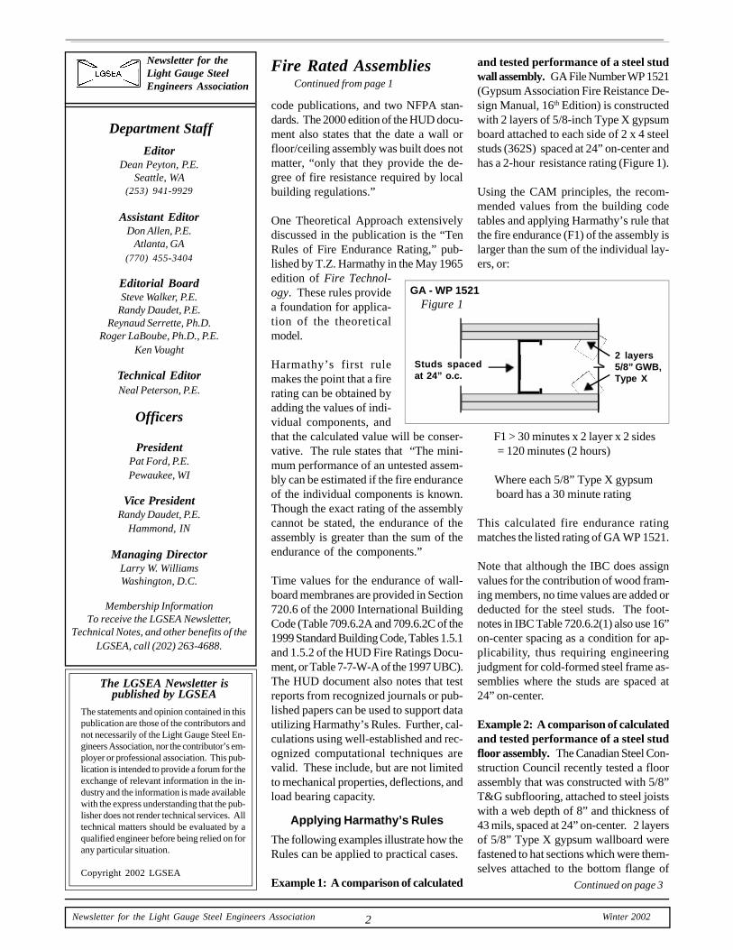
and tested performance of a steel studwall assembly. GA File Number WP 1521(Gypsum Association Fire Reistance De-sign Manual, 16th Edition) is constructedwith 2 layers of 5/8-inch Type X gypsumboard attached to each side of 2 x 4 steelstuds (362S) spaced at 24” on-center andhas a 2-hour resistance rating (Figure 1).
Using the CAM principles, the recom-mended values from the building codetables and applying Harmathy’s rule thatthe fire endurance (F1) of the assembly islarger than the sum of the individual lay-ers, or:
F1 > 30 minutes x 2 layer x 2 sides = 120 minutes (2 hours)
Where each 5/8” Type X gypsum board has a 30 minute rating
This calculated fire endurance ratingmatches the listed rating of GA WP 1521.
Note that although the IBC does assignvalues for the contribution of wood fram-ing members, no time values are added ordeducted for the steel studs. The foot-notes in IBC Table 720.6.2(1) also use 16”on-center spacing as a condition for ap-plicability, thus requiring engineeringjudgment for cold-formed steel frame as-semblies where the studs are spaced at24” on-center.
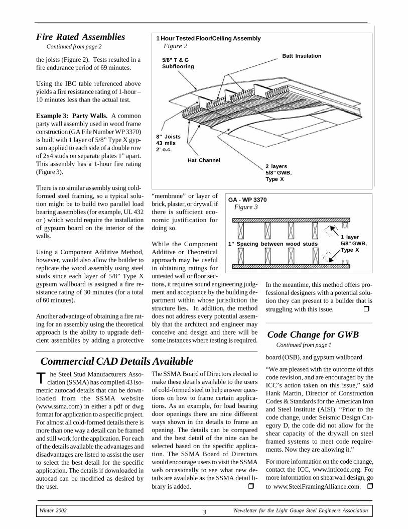
Example 2: A comparison of calculatedand tested performance of a steel studfloor assembly. The Canadian Steel Con-struction Council recently tested a floorassembly that was constructed with 5/8”T&G subflooring, attached to steel joistswith a web depth of 8” and thickness of43 mils, spaced at 24” on-center. 2 layersof 5/8” Type X gypsum wallboard werefastened to hat sections which were them-selves attached to the bottom flange of
Figure 1GA - WP 1521
Fire Rated AssembliesContinued from page 1
Continued on page 3
Studs spacedat 24” o.c.
2 layers5/8” GWB,Type X
3 Winter 2002 Newsletter for the Light Gauge Steel Engineers Association
the joists (Figure 2). Tests resulted in afire endurance period of 69 minutes.
Using the IBC table referenced aboveyields a fire resistance rating of 1-hour –10 minutes less than the actual test.
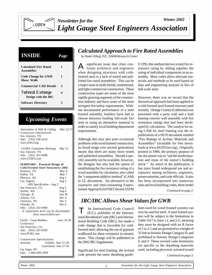
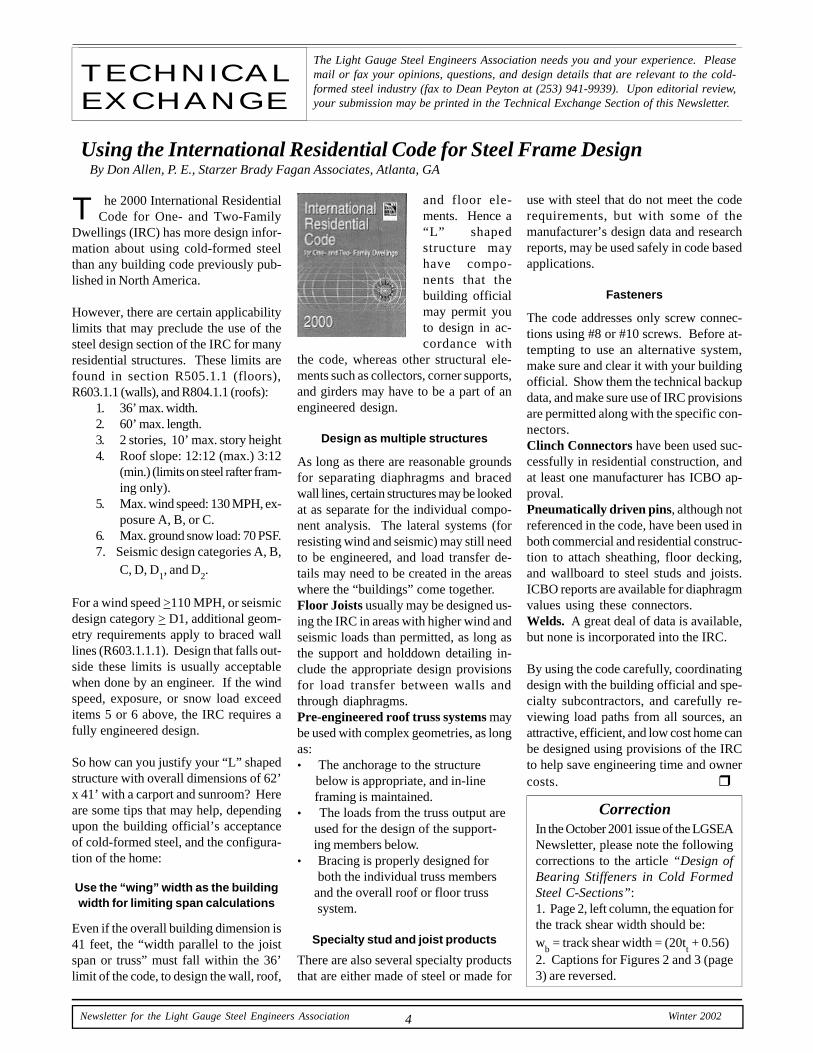
Example 3: Party Walls. A commonparty wall assembly used in wood frameconstruction (GA File Number WP 3370)is built with 1 layer of 5/8” Type X gyp-sum applied to each side of a double rowof 2x4 studs on separate plates 1” apart.This assembly has a 1-hour fire rating(Figure 3).
There is no similar assembly using cold-formed steel framing, so a typical solu-tion might be to build two parallel loadbearing assemblies (for example, UL 432or ) which would require the installationof gypsum board on the interior of thewalls.
Using a Component Additive Method,however, would also allow the builder toreplicate the wood assembly using steelstuds since each layer of 5/8” Type Xgypsum wallboard is assigned a fire re-sistance rating of 30 minutes (for a totalof 60 minutes).
Another advantage of obtaining a fire rat-ing for an assembly using the theoreticalapproach is the ability to upgrade defi-cient assemblies by adding a protective
“membrane” or layer ofbrick, plaster, or drywall ifthere is sufficient eco-nomic justification fordoing so.
While the ComponentAdditive or Theoreticalapproach may be usefulin obtaining ratings foruntested wall or floor sec-tions, it requires sound engineering judg-ment and acceptance by the building de-partment within whose jurisdiction thestructure lies. In addition, the methoddoes not address every potential assem-bly that the architect and engineer mayconceive and design and there will besome instances where testing is required.
board (OSB), and gypsum wallboard.
“We are pleased with the outcome of thiscode revision, and are encouraged by theICC’s action taken on this issue,” saidHank Martin, Director of ConstructionCodes & Standards for the American Ironand Steel Institute (AISI). “Prior to thecode change, under Seismic Design Cat-egory D, the code did not allow for theshear capacity of the drywall on steelframed systems to meet code require-ments. Now they are allowing it.”
For more information on the code change,contact the ICC, www.intlcode.org. Formore information on shearwall design, goto www.SteelFramingAlliance.com. r
Code Change for GWBContinued from page 1
he Steel Stud Manufacturers Asso- ciation (SSMA) has compiled 43 iso-metric autocad details that can be down-loaded from the SSMA website(www.ssma.com) in either a pdf or dwgformat for application to a specific project.For almost all cold-formed details there ismore than one way a detail can be framedand still work for the application. For eachof the details available the advantages anddisadvantages are listed to assist the userto select the best detail for the specificapplication. The details if downloaded inautocad can be modified as desired bythe user.
Commercial CAD Details AvailableThe SSMA Board of Directors elected tomake these details available to the usersof cold-formed steel to help answer ques-tions on how to frame certain applica-tions. As an example, for load bearingdoor openings there are nine differentways shown in the details to frame anopening. The details can be comparedand the best detail of the nine can beselected based on the specific applica-tion. The SSMA Board of Directorswould encourage users to visit the SSMAweb occasionally to see what new de-tails are available as the SSMA detail li-brary is added. r
GA - WP 3370Figure 3
T
1 Hour Tested Floor/Ceiling AssemblyFigure 2
In the meantime, this method offers pro-fessional designers with a potential solu-tion they can present to a builder that isstruggling with this issue. r
Fire Rated AssembliesContinued from page 2
5/8” T & GSubflooring
Batt Insulation
8” Joists43 mils2’ o.c.
2 layers5/8” GWB,Type X
Hat Channel
1” Spacing between wood studs1 layer5/8” GWB,Type X
4Newsletter for the Light Gauge Steel Engineers Association Winter 2002
TECHNICALEXCHANGE
The Light Gauge Steel Engineers Association needs you and your experience. Pleasemail or fax your opinions, questions, and design details that are relevant to the cold-formed steel industry (fax to Dean Peyton at (253) 941-9939). Upon editorial review,your submission may be printed in the Technical Exchange Section of this Newsletter.
Using the International Residential Code for Steel Frame DesignBy Don Allen, P. E., Starzer Brady Fagan Associates, Atlanta, GA
T he 2000 International Residential Code for One- and Two-FamilyDwellings (IRC) has more design infor-mation about using cold-formed steelthan any building code previously pub-lished in North America.
However, there are certain applicabilitylimits that may preclude the use of thesteel design section of the IRC for manyresidential structures. These limits arefound in section R505.1.1 (floors),R603.1.1 (walls), and R804.1.1 (roofs):
1. 36’ max. width.2. 60’ max. length.3. 2 stories, 10’ max. story height4. Roof slope: 12:12 (max.) 3:12
(min.) (limits on steel rafter fram-ing only).
5. Max. wind speed: 130 MPH, ex-posure A, B, or C.
6. Max. ground snow load: 70 PSF.7. Seismic design categories A, B,
C, D, D1, and D
2.
For a wind speed >110 MPH, or seismicdesign category > D1, additional geom-etry requirements apply to braced walllines (R603.1.1.1). Design that falls out-side these limits is usually acceptablewhen done by an engineer. If the windspeed, exposure, or snow load exceeditems 5 or 6 above, the IRC requires afully engineered design.
So how can you justify your “L” shapedstructure with overall dimensions of 62’x 41’ with a carport and sunroom? Hereare some tips that may help, dependingupon the building official’s acceptanceof cold-formed steel, and the configura-tion of the home:
Use the “wing” width as the buildingwidth for limiting span calculations
Even if the overall building dimension is41 feet, the “width parallel to the joistspan or truss” must fall within the 36’limit of the code, to design the wall, roof,
and floor ele-ments. Hence a“L” shapedstructure mayhave compo-nents that thebuilding officialmay permit youto design in ac-cordance with
the code, whereas other structural ele-ments such as collectors, corner supports,and girders may have to be a part of anengineered design.
Design as multiple structures
As long as there are reasonable groundsfor separating diaphragms and bracedwall lines, certain structures may be lookedat as separate for the individual compo-nent analysis. The lateral systems (forresisting wind and seismic) may still needto be engineered, and load transfer de-tails may need to be created in the areaswhere the “buildings” come together.Floor Joists usually may be designed us-ing the IRC in areas with higher wind andseismic loads than permitted, as long asthe support and holddown detailing in-clude the appropriate design provisionsfor load transfer between walls andthrough diaphragms.Pre-engineered roof truss systems maybe used with complex geometries, as longas:• The anchorage to the structure below is appropriate, and in-line framing is maintained.• The loads from the truss output are used for the design of the support- ing members below.• Bracing is properly designed for both the individual truss members and the overall roof or floor truss system.
Specialty stud and joist products
There are also several specialty productsthat are either made of steel or made for
use with steel that do not meet the coderequirements, but with some of themanufacturer’s design data and researchreports, may be used safely in code basedapplications.
Fasteners
The code addresses only screw connec-tions using #8 or #10 screws. Before at-tempting to use an alternative system,make sure and clear it with your buildingofficial. Show them the technical backupdata, and make sure use of IRC provisionsare permitted along with the specific con-nectors.Clinch Connectors have been used suc-cessfully in residential construction, andat least one manufacturer has ICBO ap-proval.Pneumatically driven pins, although notreferenced in the code, have been used inboth commercial and residential construc-tion to attach sheathing, floor decking,and wallboard to steel studs and joists.ICBO reports are available for diaphragmvalues using these connectors.Welds. A great deal of data is available,but none is incorporated into the IRC.
By using the code carefully, coordinatingdesign with the building official and spe-cialty subcontractors, and carefully re-viewing load paths from all sources, anattractive, efficient, and low cost home canbe designed using provisions of the IRCto help save engineering time and ownercosts. r
CorrectionIn the October 2001 issue of the LGSEANewsletter, please note the followingcorrections to the article “Design ofBearing Stiffeners in Cold FormedSteel C-Sections”:1. Page 2, left column, the equation forthe track shear width should be:w
b = track shear width = (20t
t + 0.56)
2. Captions for Figures 2 and 3 (page3) are reversed.
5 Winter 2002 Newsletter for the Light Gauge Steel Engineers Association
Pro
gra
m/
C
od
esC
on
tact
a
nd
In
pu
t/In
terf
ace
Des
crip
tio
n
D
esig
n M
od
ule
s
Str
uct
ura
l
Dem
o?
/
Info
.S
tan
dar
ds
Co
mp
on
ents
Pri
ce
1996
AIS
ISp
ecif
icat
ion,
incl
udin
g th
e19
99 S
uppl
e-m
ent,
and
the
1986
edi
tion
with
198
9ad
dend
a.
1996
AIS
ISp
ecif
icat
ion
Supp
lem
ent #
119
90 A
SCE
Spec
ific
atio
n (f
orst
ainl
ess
stee
l)
ASC
E7,
BO
CA
,U
BC
, SB
C,
Can
adia
n,A
ustr
alia
n,B
ritis
h, F
renc
h,Ja
pane
se, I
nter
’l,
Flor
ida,
Pue
rto
Ric
o, C
arib
bean
,an
d Ph
ilipp
ines
Uni
form
load
s, b
eari
ng le
ngth
s an
d br
acin
g in
terv
als
(fle
xura
l and
axi
al)
are
inpu
t fro
m a
gra
phic
s sc
reen
.Se
ctio
ns a
re c
hose
n fr
om d
rop-
dow
n st
yle
data
base
boxe
s or
inpu
t fro
m a
gra
phic
s sc
reen
. Allo
wab
le s
pan
leng
ths
are
gene
rate
d fo
r cu
rtai
n w
all a
nd jo
ist f
ram
ing
chec
ks. S
ectio
ns c
an b
e m
odif
ied
inte
ract
ivel
y, a
llow
ing
the
user
to s
elec
t the
mos
t eff
icie
nt m
embe
r fo
r th
eap
plic
atio
n.
Win
dow
s in
terf
ace
allo
win
g se
vera
l file
s op
en a
t onc
e.Se
ctio
n W
izar
d an
d A
naly
sis
Wiz
ard
for
quic
k cr
eatio
nof
des
ign
prob
lem
. G
raph
ical
dis
play
acc
ompa
nied
by
num
erou
s ed
iting
tech
niqu
es.
Mes
sage
s on
exc
eede
dlim
its (
w/t,
D/t,
KL
/r, e
tc.)
. O
utpu
t sha
pe g
eom
etry
to.D
XF
file
. In
tegr
ated
Hel
p fi
le d
ocum
enta
tion.
FRA
ME
D&
E 6
.0 is
an
inte
grat
ed a
naly
sis
and
desi
gnso
ftw
are
prog
ram
for
the
desi
gn o
f bu
ildin
g w
alls
and
floo
r fr
amin
g fa
bric
ated
fro
m li
ght g
auge
ste
el s
ectio
ns.
The
Fra
me
D p
rogr
am w
ill s
elec
t the
mos
t eco
nom
ical
fram
ing
for
spec
ifie
d lo
ads
and
span
con
ditio
ns.
Com
preh
ensi
ve r
epor
ts, s
tep
thro
ugh
men
us, a
ndon
line
help
mak
e Fr
ame
D&
E e
asy
to u
se.
•
Des
ign
wal
l stu
ds (
com
bine
d lo
aded
or
curt
ain
wal
l), f
loor
jois
ts, c
eilin
g jo
ists
, pos
ts a
nd b
race
s
(
pure
axi
al)
and
head
ers
or b
eam
s.
•
Sin
gle,
box
ed a
nd b
ack-
to-b
ack
mem
bers
.
•A
ny g
ener
al c
old-
form
ed s
teel
sha
pe, i
nclu
ding
clos
ed s
hape
s an
d bu
ilt-u
p se
ctio
ns.
•Fu
ll, n
et, a
nd e
ffec
tive
sect
ion
prop
ertie
s.•
LR
FD a
nd A
SD s
tren
gths
for
com
pres
sion
,te
nsio
n, m
omen
ts, s
hear
s, a
nd w
eb c
ripp
ling.
•St
reng
th in
crea
se d
ue to
col
d w
ork
of f
orm
ing
•A
xial
/ben
ding
, ben
ding
/she
ar, b
endi
ng/w
eb-
crip
plin
g in
tera
ctio
ns.
•C
ontin
uous
bea
m/c
olum
n an
alys
is w
ith b
iaxi
albe
ndin
g.•
Ela
stic
buc
klin
g an
alys
is u
sing
the
Fini
te S
trip
met
hod.
Ana
lysi
s m
ay in
clud
e:•
Scre
w, w
eld,
or
bolt
conn
ectio
ns•
Seis
mic
Coe
ffic
ient
Cal
cula
tion
•Sh
ear
wal
l ana
lysi
s•
Floo
r an
d ro
of d
iaph
ragm
ana
lysi
s•
Mul
tiple
flo
or le
vels
•E
xter
ior
and
inte
rior
load
bea
ring
wal
l stu
ds•
H
eade
rs, b
eam
s, f
loor
jois
ts, a
nd s
uppo
rt c
olum
ns.
SSM
A a
nd c
usto
mda
taba
ses.
Dat
abas
es f
or S
SMA
,H
UD
, and
LG
SIse
ctio
ns
Knu
dson
rol
lfor
mer
s,SS
MA
, Dal
e/In
cor,
Die
tric
h, A
ISC
,Pr
opri
etar
y sh
apes
,pl
us o
ther
s.
FRE
Edo
wnl
oad
from
ww
w.c
lark
stee
l.c
om Yes
$550
Yes
, on
web
site
.
$795
AIS
IWIN
v4.
0
Cla
rk S
teel
Fram
ing
(888
) 43
7-32
44jo
ew@
clar
kste
el.c
omw
ww
.cla
rkst
eel.c
om
CFS
®
Ver
sion
3.5
RSG
Sof
twar
e(8
16)
524-
5596
info
@rs
gsof
twar
e.co
mw
ww
.rs
gsof
twar
e.co
m
FRA
ME
D&
E
JFB
& A
ssoc
.(7
19)
598-
7666
ww
w.J
FBA
.com
CC
old-
For
med
Ste
el D
esig
n So
ftw
are
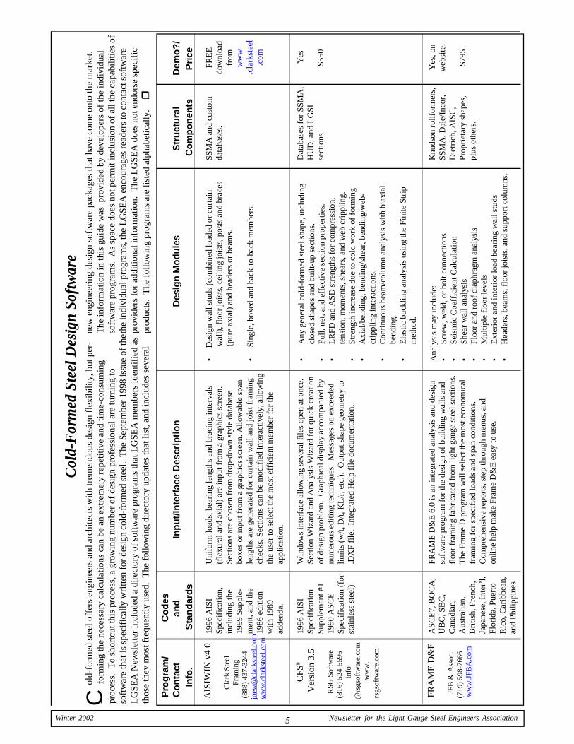
old
-for
med
ste
el o
ffer
s en
gine
ers
and
arch
itect
s w
ith tr
emen
dous
des
ign
flex
ibili
ty, b
ut p
er-
-
for
min
g th
e ne
cess
ary
calc
ulat
ions
can
be
an e
xtre
mel
y re
petit
ive
and
time-
cons
umin
gpr
oces
s. T
o sh
ortc
ut th
is p
roce
ss, a
gro
win
g nu
mbe
r of
des
ign
prof
essi
onal
are
turn
ing
toso
ftw
are
that
is s
peci
fica
lly w
ritte
n fo
r de
sign
col
d-fo
rmed
ste
el.
The
Sep
tem
ber
1998
issu
e of
the
LG
SEA
New
slet
ter
incl
uded
a d
irec
tory
of
soft
war
e pr
ogra
ms
that
LG
SEA
mem
bers
iden
tifie
d as
thos
e th
ey m
ost f
requ
ently
use
d. T
he f
ollo
win
g di
rect
ory
upda
tes
that
list
, and
incl
udes
sev
eral
new
eng
inee
ring
des
ign
soft
war
e pa
ckag
es th
at h
ave
com
e on
to th
e m
arke
t.T
he in
form
atio
n in
this
gui
de w
as p
rovi
ded
by d
evel
oper
s of
the
indi
vidu
also
ftw
are
prog
ram
s. A
s sp
ace
does
not
per
mit
incl
usio
n of
all
the
capa
bilit
ies
ofth
e in
divi
dual
pro
gram
s, th
e L
GSE
A e
ncou
rage
s re
ader
s to
con
tact
sof
twar
epr
ovid
ers
for
addi
tiona
l inf
orm
atio
n. T
he L
GSE
A d
oes
not e
ndor
se s
peci
fic
prod
ucts
. T
he f
ollo
win
g pr
ogra
ms
are
liste
d al
phab
etic
ally
. r

6Newsletter for the Light Gauge Steel Engineers Association Winter 2002
Pro
gra
m/
C
od
esC
on
tact
a
nd
In
pu
t/In
terf
ace
Des
crip
tio
n
D
esig
n M
od
ule
s
Str
uct
ura
l
Dem
o?
/
Info
.S
tan
dar
ds
Co
mp
on
ents
Pri
ce
Key
Bui
ld®
Key
mar
kE
nter
pris
es(3
03)
443-
8033
ww
w.
keym
ark.
com
LG
BE
AM
ER
Dev
co S
oftw
are
(541
) 75
7-89
91ro
b@de
vco
soft
war
e.co
mw
ww
.dev
coso
ftw
are.
com
LtF
ram
er
aecI
T S
olut
ions
Cor
pora
tion
(407
) 64
5-13
03sa
les@
aeci
t.ne
t
1986
AIS
ISp
ecif
icat
ion,
with
198
9A
dden
da a
nd19
96 E
ditio
n
1996
AIS
ISp
ecif
icat
ion,
incl
udin
g th
e19
99 S
uppl
emen
t, a
nd th
e 19
86ed
ition
with
198
9ad
dend
a
1996
AIS
ISp
ecif
icat
ion
Key
Bui
ld®
allo
ws
a us
er to
des
crib
e th
e ge
omet
ry o
fen
tire
stru
ctur
es u
sing
the
Key
Bui
ld M
odel
™, a
ful
lyfu
nctio
nal 3
-dim
ensi
onal
mod
elin
g pr
ogra
m.
Inad
ditio
n to
the
mat
eria
ls a
nd lo
ads,
the
user
def
ines
the
wal
ls, t
russ
es, f
ram
ing
mat
eria
ls, a
nd f
ound
atio
n in
ful
l3-
D.
Key
Bui
ld M
ode™
use
s “m
arco
” in
put t
o al
low
the
user
to q
uick
ly a
nd e
asily
def
ine
com
plet
e ro
ofsy
stem
s, c
eilin
g va
ults
, eve
n sk
ylig
ht a
nd d
orm
erfr
amin
g.
Span
leng
ths,
load
s (u
nifo
rm, c
once
ntra
ted,
and
axi
al),
bear
ing
leng
ths
and
brac
ing
inte
rval
s (f
lexu
ral a
nd a
xial
)ar
e in
put f
rom
a g
raph
ics
scre
en.
Sect
ions
are
cho
sen
from
dro
p-do
wn
styl
e da
taba
se b
oxes
or
inpu
t fro
m a
grap
hics
scr
een.
Sec
tions
can
be
mod
ifie
d in
tera
ctiv
ely,
allo
win
g th
e us
er to
sel
ect t
he m
ost e
ffic
ient
mem
ber
for
the
appl
icat
ion.
LtF
ram
er is
a 3
d m
odel
ing
and
engi
neer
ing
anal
ysis
sof
t-w
are
prod
uct f
or th
e pr
epar
atio
n of
eng
inee
red
CFS
ligh
tfr
ame
com
pone
nts
for
build
ing
syst
ems.
The
pro
duct
isba
sed
on A
utoC
AD
200
0 gr
aphi
cs a
nd in
terf
ace
tech
nol-
ogy.
Aut
oCA
D o
wne
rshi
p is
not
req
uire
d. T
he U
I is
sim
plif
ied
and
focu
sed
tow
ards
the
fram
ing
desi
gner
and
stru
ctur
al a
naly
st m
inim
izin
g th
e ne
ed to
for
adv
ance
dC
AD
ski
lls.
The
maj
ority
of
the
labo
r re
quir
ed to
pro
-du
ce s
truc
tura
l mod
els,
fab
rica
tion
and
erec
tion
docu
-m
ents
and
rep
orts
for
Eng
inee
red
CFS
Com
pone
nts
isau
tom
ated
, dra
win
g an
d re
port
for
mat
s ar
e fl
exib
le.
•D
esig
ns a
ll jo
ists
, hea
ders
, bea
ms,
and
gir
ders
•R
oof
or f
loor
trus
ses
are
desi
gned
for
sta
ndar
dgr
avity
load
s•
Loa
ds f
rom
the
roof
or
floo
r m
embe
rs a
re p
asse
dth
roug
h th
e w
all,
to th
e le
vel b
elow
. C
ompl
ete
wal
l lay
out a
nd e
leva
tion
plot
s ca
n th
en b
ege
nera
ted
•A
ll of
the
load
s in
the
stru
ctur
e ar
e tr
acke
d, a
nd a
reav
aila
ble
for
foun
datio
n en
gine
erin
g•
Win
d an
d se
ism
ic lo
ads
gene
rate
d fo
r la
tera
l des
ign
•
All
mat
eria
ls in
the
build
ing
can
then
be
cons
oli-
da
ted,
then
cut
she
ets
and
mat
eria
ls li
sts
can
be
outp
ut
•D
esig
ns s
tuds
, joi
sts,
trac
ks, h
eade
rs, a
nd b
eam
s of
chan
nel “
C”
or “
Z”
shap
es.
•G
raph
ical
ly m
odel
up
to th
ree
span
s w
ithca
ntile
vers
.•
Uni
form
, con
cent
rate
d, a
xial
and
com
bine
d lo
ads.
•
Sin
gle,
box
ed, b
ack-
to-b
ack
and
built
-up
mem
bers
•T
he L
tFra
mer
Mat
eria
ls M
odel
ing
Mod
ules
are
the
Wal
l, Fl
oor
and
Roo
f W
orks
hops
– F
abri
catio
n dr
aw-
ings
& m
ater
ials
list
s w
ith c
uttin
g in
form
atio
n ar
epr
oduc
ed u
sing
thes
e m
odul
es.
•T
he E
ngin
eeri
ng A
naly
sis
Stud
io M
odul
e pr
ovid
esfl
exib
le, p
ower
ful S
truc
tura
l Ana
lysi
s an
d A
ISI
code
chec
king
. T
his
mod
ule
exte
nds
the
capa
bilit
ies
ofth
e m
ater
ials
wor
ksho
ps.
•C
onte
xt S
ensi
tive
Hel
p Sy
stem
•M
ater
ials
and
ana
lysi
s re
port
s ca
n ex
port
to M
SE
xcel
or
othe
r C
SV c
apab
le p
rodu
cts.
•O
nlin
e de
mo,
trai
ning
and
tech
nica
l ass
ista
nce.
•Fl
oor
& R
oof
Wor
ksho
ps a
re u
nder
dev
elop
men
tch
eck
for
avai
labi
lity.
Prop
riet
ary
and/
or“C
” se
ctio
n m
ater
ials
SSM
A,
MSM
A,
indi
vidu
al s
tud
man
ufac
ture
rs,
“Z”
sect
ion,
and
cus
tom
data
base
s
Sect
ion
Dat
abas
es f
orM
SMA
are
sta
ndar
d,ot
hers
can
be
prov
ided
.B
uilt
Up
Sect
ion
as-
sem
blie
s ca
n be
use
d.A
naly
sis
of s
tand
ard
and
cust
om c
ompo
-ne
nts
that
can
be
fabr
icat
ed f
rom
CFS
stud
and
trac
km
ater
ials
is s
up-
port
ed.
Yes
Cal
l for
pric
ing
Yes
$ 37
5
Yes
Onl
ine
Dem
osav
aila
ble
30 d
ay tr
ybe
fore
you
buy
optio
n.
Con
tact
sale
sgro
upfo
r le
ase
pric
es.
Con
tinu
ed fr
om p
age
5C
old-
For
med
Ste
el D
esig
n So
ftw
are
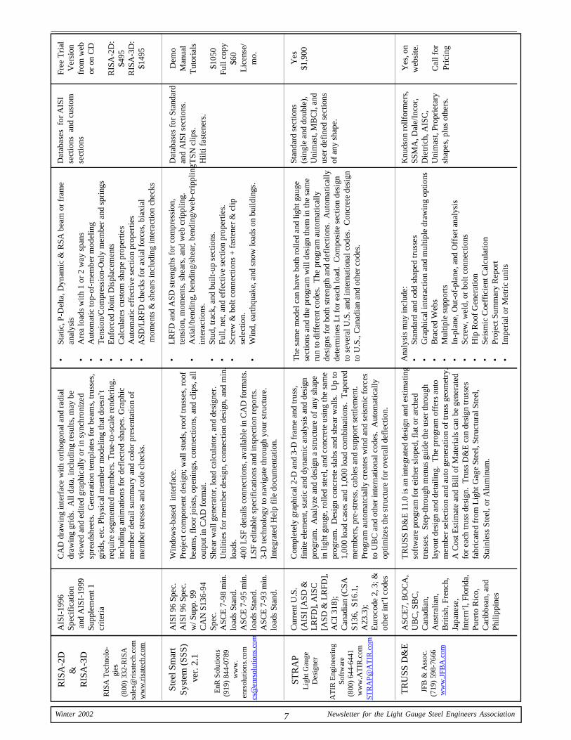
7 Winter 2002 Newsletter for the Light Gauge Steel Engineers Association
RIS
A-2
D&
RIS
A-3
D
RIS
A T
echn
olo-
gies
(800
) 33
2-R
ISA
sale
s@ri
sate
ch.c
omw
ww
.ris
atec
h.co
m
Stee
l Sm
art
Syst
em (
SSS)
ver
. 2.1
EnR
Sol
utio
ns(9
19)
844-
0789
ww
w.
enrs
olut
ions
.com
cs@
enrs
olut
ions
.com
STR
AP
Lig
ht G
auge
Des
igne
r
AT
IR E
ngin
eeri
ngSo
ftw
are
(800
) 64
4-64
41w
ww
.AT
IR.c
omST
RA
P@A
TIR
.com
TR
USS
D&
E
JFB
& A
ssoc
.(7
19)
598-
7666
ww
w.J
FBA
.com
AIS
I-19
96Sp
ecif
icat
ion
and
AIS
I-19
99Su
pple
men
t 1cr
iteri
a
AIS
I 96
Spe
c.A
ISI
96 S
pec.
w/ S
upp.
99
CA
N S
136-
94Sp
ec.
ASC
E 7
-98
min
.lo
ads
Stan
d.A
SCE
7-9
5 m
in.
load
s St
and.
ASC
E 7
-93
min
.lo
ads
Stan
d.
Cur
rent
U.S
.(A
ISI
[ASD
&L
RFD
], A
ISC
[ASD
& L
RFD
],A
CI
318)
;C
anad
ian
(CSA
S136
, S1
6.1,
A23
.3);
Eur
ocod
e 2,
3; &
othe
r in
t’l c
odes
ASC
E7,
BO
CA
,U
BC
, SB
C,
Can
adia
n,A
ustr
alia
n,B
ritis
h, F
renc
h,Ja
pane
se,
Inte
rn’l
, Flo
rida
,Pu
erto
Ric
o,C
arib
bean
, and
Phili
ppin
es
CA
D d
raw
ing
inte
rfac
e w
ith o
rtho
gona
l and
rad
ial
draw
ing
grid
s. A
ll da
ta, i
nclu
ding
res
ults
, may
be
view
ed a
nd e
dite
d gr
aphi
cally
or
in s
ynch
roni
zed
spre
adsh
eets
. G
ener
atio
n te
mpl
ates
for
bea
ms,
trus
ses,
grid
s, e
tc. P
hysi
cal m
embe
r m
odel
ing
that
doe
sn’t
requ
ire
segm
ente
d m
embe
rs. T
rue-
to-s
cale
ren
deri
ng,
incl
udin
g an
imat
ions
for
def
lect
ed s
hape
s. G
raph
icm
embe
r de
tail
sum
mar
y an
d co
lor
pres
enta
tion
ofm
embe
r st
ress
es a
nd c
ode
chec
ks.
Win
dow
s-ba
sed
inte
rfac
e.Pr
ojec
t com
pone
nt d
esig
n; w
all s
tuds
, roo
f tr
usse
s, r
oof
beam
s, f
loor
jois
ts, o
peni
ngs,
con
nect
ions
, and
clip
s, a
llou
tput
in C
AD
for
mat
.Sh
ear
wal
l gen
erat
or, l
oad
calc
ulat
or, a
nd d
esig
ner.
Util
ities
for
mem
ber
desi
gn, c
onne
ctio
n de
sign
, and
min
.lo
ads.
400
LSF
det
ails
con
nect
ions
, ava
ilabl
e in
CA
D f
orm
ats.
LSF
edi
tabl
e sp
ecif
icat
ions
and
insp
ectio
n re
port
s.3-
D te
chno
logy
to n
avig
ate
thro
ugh
your
str
uctu
re.
Inte
grat
ed H
elp
file
doc
umen
tatio
n.
Com
plet
ely
grap
hica
l 2-D
and
3-D
fra
me
and
trus
s,fi
nite
ele
men
t, st
atic
and
dyn
amic
ana
lysi
s an
d de
sign
prog
ram
. A
naly
ze a
nd d
esig
n a
stru
ctur
e of
any
sha
pein
ligh
t gau
ge, r
olle
d st
eel,
and
conc
rete
usi
ng th
e sa
me
prog
ram
. D
esig
n co
ncre
te s
labs
and
she
ar w
alls
. U
p to
1,00
0 lo
ad c
ases
and
1,0
00 lo
ad c
ombi
natio
ns.
Tap
ered
mem
bers
, pre
-str
ess,
cab
les
and
supp
ort s
ettle
men
t.Pr
ogra
m a
utom
atci
ally
cre
ates
win
d an
d se
ism
ic f
orce
sto
UB
C a
nd o
ther
inte
rnat
iona
l cod
es.
Aut
omat
ical
lyop
timiz
es th
e st
ruct
ure
for
over
all d
efle
ctio
n.
TR
USS
D&
E 1
1.0
is a
n in
tegr
ated
des
ign
and
estim
atin
gso
ftw
are
prog
ram
for
eith
er s
lope
d, f
lat o
r ar
ched
trus
ses.
Ste
p-th
roug
h m
enus
gui
de th
e us
er th
roug
hla
yout
des
ign
and
deta
iling
. T
he p
rogr
am o
ffer
s au
tom
embe
r se
lect
ion
and
auto
gen
erat
ion
of tr
uss
geom
etry
.A
Cos
t Est
imat
e an
d B
ill o
f M
ater
ials
can
be
gene
rate
dfo
r ea
ch tr
uss
desi
gn.
Tru
ss D
&E
can
des
ign
trus
ses
fabr
icat
ed f
rom
Lig
ht G
age
Stee
l, St
ruct
ural
Ste
el,
Stai
nles
s St
eel,
or A
lum
inum
.
•St
atic
, P-D
elta
, Dyn
amic
& R
SA b
eam
or
fram
ean
alys
is•
Are
a lo
ads
with
1 o
r 2
way
spa
ns•
Aut
omat
ic to
p-of
-mem
ber
mod
elin
g•
Ten
sion
/Com
pres
sion
-Onl
y m
embe
r an
d sp
ring
s•
Enf
orce
d Jo
int D
ispl
acem
ents
•C
alcu
late
s cu
stom
sha
pe p
rope
rtie
s•
Aut
omat
ic e
ffec
tive
sect
ion
prop
ertie
s•
A
SD/L
RFD
che
cks
for
axia
l for
ces,
bia
xial
m
omen
ts &
she
ars
incl
udin
g in
tera
ctio
n ch
ecks
•L
RFD
and
ASD
str
engt
hs f
or c
ompr
essi
on,
tens
ion,
mom
ents
, she
ars,
and
web
cri
pplin
g.•
Axi
al/b
endi
ng, b
endi
ng/s
hear
, ben
ding
/web
-cri
pplin
gin
tera
ctio
ns.
•St
ud, t
rack
, and
bui
lt-up
sec
tions
.•
Full,
net
, and
eff
ectiv
e se
ctio
n pr
oper
ties.
•Sc
rew
& b
olt c
onne
ctio
ns +
fas
tene
r &
clip
sele
ctio
n.•
Win
d, e
arth
quak
e, a
nd s
now
load
s on
bui
ldin
gs.
The
sam
e m
odel
can
hav
e bo
th r
olle
d an
d lig
ht g
auge
sect
ions
and
the
prog
ram
will
des
ign
them
in th
e sa
me
run
to d
iffe
rent
cod
es.
The
pro
gram
aut
omat
ical
lyde
sign
s fo
r bo
th s
tren
gth
and
defl
ectio
ns.
Aut
omat
ical
lyde
term
ines
Lt f
or e
ach
load
. C
ompo
site
sec
tion
desi
gnto
sev
eral
U.S
. and
inte
rnat
iona
l cod
es.
Con
cret
e de
sign
to U
.S.,
Can
adia
n an
d ot
her
code
s.
Ana
lysi
s m
ay in
clud
e:•
Stan
dard
and
odd
sha
ped
trus
ses
•G
raph
ical
inte
ract
ion
and
mul
tiple
dra
win
g op
tions
•B
race
d W
ebs
•M
ultip
le s
uppo
rts
•In
-pla
ne, O
ut-o
f-pl
ane,
and
Off
set a
naly
sis
•Sc
rew
, wel
d, o
r bo
lt co
nnec
tions
•H
ip R
oof
Gen
erat
ion
•Se
ism
ic C
oeff
icie
nt C
alcu
latio
n•
Proj
ect S
umm
ary
Rep
ort
•
Im
peri
al o
r M
etri
c un
its
Dat
abas
es f
or A
ISI
sect
ions
and
cus
tom
sect
ions
Dat
abas
es f
or S
tand
ard
and
AIS
I se
ctio
ns.
TSN
clip
s.H
ilti f
aste
ners
.
Stan
dard
sec
tions
(sin
gle
and
doub
le),
Uni
mas
t, M
BC
I, a
ndus
er d
efin
ed s
ectio
nsof
any
sha
pe.
Knu
dson
rol
lfor
mer
s,SS
MA
, Dal
e/In
cor,
Die
tric
h, A
ISC
,U
nim
ast,
Prop
riet
ary
shap
es, p
lus
othe
rs.
Free
Tri
alV
ersi
onfr
om w
ebor
on
CD
RIS
A-2
D:
$495
RIS
A-3
D:
$149
5
Dem
oM
anua
lT
utor
ials
$105
0Fu
ll co
py$6
0L
icen
se/
mo.
Yes
$1,9
00
Yes
, on
web
site
.
Cal
l for
Pric
ing
8Newsletter for the Light Gauge Steel Engineers Association Winter 2002
Light Gauge Steel Engineers Association1726 M Street, N.W., Suite 601Washington, D.C. 20036(202) 263-4488
Standardizing theCold-Formed Steel Industry
Headquarters Office 8 S. Michigan Avenue., #1000 Chicago, IL 60603 (312) 456-5590 FAX: (312) 580-0165
E-Mail: [email protected]
Technical Services Office 245 N.E. Conifer Blvd. P.O. Box 1211 Corvallis, OR 97339 (541) 757-8991 FAX: (541) 757-9885 E-Mail: [email protected]
TrusSteel Division Alpine Engineered Products, Inc.
888-565-9181 dgoodw [email protected]
Questions about light gauge steel trusses?
We have answers.
Order your free
Design Resource CD today. Product Descriptions DXF & DWG Details
Case Histories Guide Specs ICBO Report NES Report UL Listings
www.TrusSteel.com
Trust. Vision. Growth. World ClassQuality
&Service
The largest steelmakerin the Western United States
900 Loveridge RoadPittsburg, CA 94565www.uss-posco.com
Ranked #1 in OverallCustomer Satisfaction