WinPro V4 2 english - Gasdetectie Verkoop Verhuur · The complete system and all required...
57
Operating Instru ctions Gas Detection System NPM 62GB Révision : D M M X X 6 6 2 2
Transcript of WinPro V4 2 english - Gasdetectie Verkoop Verhuur · The complete system and all required...

Operating Instructions Gas Detection System
NPM62GB Révision : D
MMXX6622

GAS DETECTION We are delighted that you have chosen an INDUSTRIAL SCIENTIFIC instrument and would like to thank you for your choice. We have taken all the necessary measures to ensure that your instrument provides total satisfaction. Now it is important to read this document carefully.
EE XX TT EE NN TT OO FF RR EE SS PP OO NN SS II BB II LL II TT YY * INDUSTRIAL SCIENTIFIC declines its responsibility towards any person for material damage, physical
injury or death resulting wholly or partly from inappropriate use, installation or storage of its equipment re-sulting from failure to observe instructions and warnings and/or standards and regulations in force.
* INDUSTRIAL SCIENTIFIC neither supports nor authorises any company, physical or moral person to
assume responsibility on behalf of INDUSTRIAL SCIENTIFIC , even if it is involved in the sale of INDUSTRIAL SCIENTIFIC products.
* INDUSTRIAL SCIENTIFIC cannot be held responsible for direct or indirect damage or be required to pay
direct or indirect compensation resulting from the sale or use of any of its products IF THESE PRODUCTS HAVE NOT BEEN DEFINED AND CHOSEN BY INDUSTRIAL SCIENTIFIC FOR THEIR SPECIFIC USE.
CC LL AA UU SS EE SS CC OO NN CC EE RR NN II NN GG PP RR OO PP EE RR TT YY
* Drawings, plans, specifications and information included in this document contain confidential information that is the property of INDUSTRIAL SCIENTIFIC
* None of this information may be reproduced, copied, divulged or translated, by physical, electronic or any
other means, nor used as the basis for the manufacture or sale of INDUSTRIAL SCIENTIFIC equipment or for any other reasons without prior consent from INDUSTRIAL SCIENTIFIC
WW AA RR NN II NN GG SS
* This document is not contractually binding. In the interests of its customers, INDUSTRIAL SCIENTIFIC reserves to modify the technical specifications of its equipment without notice, in order to improve its per-formance.
* READ THIS MANUAL CAREFULLY BEFORE FIRST USE OF THE EQUIPMENT: this manual
must be read by any person who is or will be responsible for using, maintaining or repairing this equipment.
* This equipment will only provide the announced performance levels if it is used, maintained and re-paired according to INDUSTRIAL SCIENTIFIC directives, by INDUSTRIAL SCIENTIFIC person-nel or by personnel approved by INDUSTRIAL SCIENTIFIC
GG UU AA RR AA NN TT EE EE
2 years guarantee in normal conditions of use on parts and technical labour, return in our workshops, excluding consumables (sensors, filters, etc.)
Subject to change without notice (Version 4.2) FE BA MX62 V4.2 E 0801SE
4
1. THE SYSTEM MX62..................................................................................................... 7
2. CONFIGURATION......................................................................................................... 7
2.1. Description of Modules..............................................................................................................................................8 2.1.1. Controller Module (CM)................................................................................................................................. 8 2.1.2. Analogue Input Module (AEM)..................................................................................................................... 8 2.1.3. LED Module ...................................................................................................................................................... 8 2.1.4. Basic Relay Module (RBM) and Extension Relay Module (REM)......................................................... 9 2.1.5. Loop Module (LOOPM) ................................................................................................................................. 9 2.1.6. Analogue Output Module (AAM)............................................................................................................... 10 2.1.7. LCD Module ................................................................................................................................................... 10 2.1.8. Analogue Input Extension Module (AEAM)............................................................................................. 10 2.1.9. LCD Copy Module......................................................................................................................................... 10 2.1.10. MIMIC Module............................................................................................................................................... 11
2.2. Description of Redundancy....................................................................................................................................12
2.3. Description of Control Panel..................................................................................................................................12
3. OPERATION OF THE SYSTEM MX62....................................................................12
3.1. Channel and System Information.........................................................................................................................12 3.1.1. ISA Procedure (slow flashing channel LEDs)........................................................................................... 14 3.1.2. General buzzer relay ...................................................................................................................................... 14
3.2. Normal Operation.....................................................................................................................................................15 3.2.1. Operating status .............................................................................................................................................. 15 3.2.2. Alarms .............................................................................................................................................................. 15 3.2.3. Channel Malfunction ..................................................................................................................................... 16 3.2.4. Negative Measured Values ........................................................................................................................... 16 3.2.5. Under scale of Measuring Range................................................................................................................. 16 3.2.6. Over scale of Measuring Range................................................................................................................... 17 3.2.7. Resetting of Alarm Signals ........................................................................................................................... 18
3.3. Start-up Mode ............................................................................................................................................................19
3.4. Maintenance Mode ...................................................................................................................................................19 3.4.1. Alarm Suspension........................................................................................................................................... 20 3.4.2. Operational Test.............................................................................................................................................. 20 3.4.3. Calibration ....................................................................................................................................................... 21 3.4.4. Channel On/Off............................................................................................................................................... 21 3.4.5. PC Communication ........................................................................................................................................ 22 3.4.6. Ignore communication fault with relay modules....................................................................................... 22 3.4.7. General alarm suspension............................................................................................................................. 23
3.5. Single Mode ................................................................................................................................................................23
3.6. System Error ..............................................................................................................................................................24
3.7. Measures against Faults ..........................................................................................................................................25
3.8. Error Codes of the Controller Module................................................................................................................26
3.9. Overview of LED Indications ................................................................................................................................28
4. OPERATING OF THE LCD MODULE.....................................................................29

5
4.1. Display of Channels ..................................................................................................................................................29
4.2. Menu .............................................................................................................................................................................29 4.2.1. System / LED-Test......................................................................................................................................... 30 4.2.2. System / System Status.................................................................................................................................. 30 4.2.3. System / System Information ....................................................................................................................... 30 4.2.4. Channel Information / Current Information............................................................................................... 30 4.2.5. Channel Information / Display of Configuration...................................................................................... 30 4.2.6. Relays............................................................................................................................................................... 30 4.2.7. Analogue Outputs ........................................................................................................................................... 30 4.2.8. Data Logger / Set-up ...................................................................................................................................... 30 4.2.9. Data Logger / Histogram............................................................................................................................... 31 4.2.10. Data Logger / Events ..................................................................................................................................... 31 4.2.11. Data Logger / 8-Hour Mean Values ............................................................................................................ 31 4.2.12. Data Logger / Format..................................................................................................................................... 32 4.2.13. Printer Settings................................................................................................................................................ 32 4.2.14. LCD Settings ................................................................................................................................................... 32
5. MAINTENANCE...........................................................................................................35
5.1. Calibration and Adjustment..................................................................................................................................35 5.1.1. Direct Calibration at the Transmitter .......................................................................................................... 35 5.1.2. Remote Calibration for Standard Transmitter ........................................................................................... 36 5.1.3. Manual and Automatic Field Adjustment of Digital Transmitter TBGW EX ..................................... 36
5.2. Transmitters ...............................................................................................................................................................36
6. TECHNICAL DATA.....................................................................................................36
7. TERMINAL CONNECTIONS, JUMPERS AND ROTARY SWITCH...................38
7.1. Controller Module (CM) .........................................................................................................................................38
7.2. Analogue Input Module (AEM) ............................................................................................................................39
7.3. Analogue Input Extension Module (AEAM) .....................................................................................................40
7.4. Basic Relay Module (RBM) and Extension Relay Module (REM) .............................................................41
7.5. Loop Module (LOOPM)..........................................................................................................................................42
7.6. Analogue Output Module (AAM).........................................................................................................................43
7.7. LCD Module / LCD Copy Module .......................................................................................................................44
7.8. MIMIC Module .........................................................................................................................................................45
8. CONNECTION AND INSTALLATION .....................................................................46
8.1. Wiring ..........................................................................................................................................................................46 8.1.1. Mains Supply................................................................................................................................................... 46 8.1.2. Connection of Relays..................................................................................................................................... 46 8.1.3. Connection of Transmitters .......................................................................................................................... 46
8.2. Installation of MX62 .................................................................................................................................................46 8.2.1. Wall-mounted Housing ................................................................................................................................. 46 8.2.2. 19"-Rack .......................................................................................................................................................... 47 8.2.3. Control Panel................................................................................................................................................... 47
6
9. CUT-OUT FOR CONTROL PANEL INSTALLATION...........................................47
10. ACCESSORIES AND SPARE PARTS...............................................................48
11. CERTIFICATES......................................................................................................48
11.1. CE Accreditation ................................................................................................................................................48
11.2. Metrological Approvals.....................................................................................................................................49
11.3. Special Conditions for Safe Operation..........................................................................................................50
12. ANNEX A: EC-DECLARATION OF CONFORMITY ........................................51
13. ANNEX B: TRANSLATION OF DATA LOGGER MESSAGES .....................52
14. ANNEX C: PLANNING AID: FUNCTIONAL SAFETY FOR MX62................52
14.1. Introduction .........................................................................................................................................................52
14.2. MX62 as a part of safety control installations in compliance with directive EN 61508...................52
14.3. Definition of safety-related functions to be effected by MX62................................................................53
14.4. Requirements for the configuration of MX62 .............................................................................................53
14.5. Failure rates .........................................................................................................................................................56
14.6. Instructions for employment ...........................................................................................................................57

7
1. The System MX62
MX62 is a stationary control system and evaluator to be used in combination with a va-riety of transmitters for continuous detection of combustible gases, toxic gases and oxy-gen. Main features are high reliability as well as remarkable flexibility. This flexibility refers to all areas, such as free programmability and placing of relays and analogue outputs as well as optional installation in wall-mounted housings, 19”-racks or control panels. Modular components allow extension of up to 64 channels, 128 relays and 64 analogue outputs as well as optional use of an LCD Module with data logger or Profibus Module, making the gas detection system suitable for all applications. The complete system and all required modifications can be set by software ConfigPro®. This software is detailed separately.
2. Configuration
The system consists of a Controller Module plus various other modules linked by digital busses. The basic configuration is as follows:
• Analogue Input Module (AEM) • Controller Module (CM) • LED Module • LCD or Logo Module
The Analogue Input Module converts the 4-20 mA of the transmitters into digital bus signals to be transmitted to the Controller Module where these are evaluated and then separately indicated for each channel according to the respective presetting. One Ana-logue Input and one LED Module are provided for eight channels each. The Controller Module can directly be employed for 64 channels.
In addition, further modules can be integrated into the system as required:
• Basic Relay Module (RBM) • Extension Relay Module (REM) • Analogue Output Module (AAM) • Loop Module (LOOPM) • LCD Data Logger Module • Profibus Module • Analogue Input Extension Module (AEAM) Each Basic Relay Module provides eight relays to be freely allocated. The Extension Relay Module allows an addition of eight relays with a minimum of space. The Analogue Output Module is available for either 4-20 mA or 0-10 V. Furthermore, all measured values and information can be displayed with the LCD Module and stored by a data logger.

8
2.1. Description of Modules
2.1.1. Controller Module (CM)
The Controller Module is the central control unit of the system for all 64 channels of maximum configuration. Two synchronously working 16-bit micro controllers redun-dantly process the measured values of the Analogue Input Modules. Via a redundant bus, the status of the relays and the analogue output signals are transmitted to the Re-lay and Analogue Output Modules respectively. Another bus transmits the measured values to the LCD and LED Module. For safety control, the Controller Module also contains relays to signal system errors, emergency operation and maintenance mode. By means of an RS232 interface, the entire system can be configured and all data can be visualized on a PC. A Centronics interface is available for connection of a printer.
2.1.2. Analogue Input Module (AEM)
The transmitters are connected to the Analogue Input Modules. Each module accom-modates up to any eight transmitters of 4-20 mA and provides an additional RS485 in-terface per channel. By this interface, communication can be established during main-tenance between a PC, connected to the Controller Module, and the respective transmitter. Up to eight Analogue Input Modules can be connected to the Controller Module. An address between 1 and 8 is allocated to each module by rotary switch.
2.1.3. LED Module
The status of each channel is indicated by LEDs (One transmitter can be connected to any channel). Operation of the keys for the respective channels displays additional in-formation about the relevant transmitters on the LCD Module and triggers further channel functions such as alarm suspension, operational test, channel disconnection and calibration mode. The LED Module consists of an LED panel for 16 channels and one or two PCBs for eight channels each.
1 92 103 114 125 136 147 158 16

9
2.1.4. Basic Relay Module (RBM) and Extension Relay Module (REM)
A Basic Relay Module has eight relays and can be extended by eight relays with a pluggable Extension Relay Module.
Redundant triggering of the relays is done via two 8-bit micro controllers. Free pa-rameter setting of the relays with the help of software ConfigPro® meets all individual requirements:
• AND/OR Logic Operation • Open and Closed Circuit Operation • Grouping • Voting • Time-delay and Slow Release • Relay Function for Buzzers • Relay Reproduction
Up to eight relay modules with a total of 128 relays can be integrated into the system. The redundant, opto-isolated RS485 bus allows spatial separation (up to 800 m) of the modules and control unit. An address between 1 and 8 is allocated to each module by rotary switch.
Open circuit: The relays are activated as soon as the respective status is recognized, i.e. the relay in-ductor pick up.
Closed circuit: The relays are activated during undisturbed operation, i.e. the relay inductor have picked up, and will be deactivated in case of alarm, i.e. the relay inductor will be re-leased.
2.1.5. Loop Module (LOOPM)
The Loop Module for MX62 offers the possibility to build a network of digital transmit-ters or to record measured values of any standard 4-20 mA transmitter by means of the Analogue Input Modules connected to a Loop Module.
The Loop Module can be employed in three different configurations:
1. As regular Loop Module with up to 16 digital transmitters (e.g. TBGW EX) linked to the closed loop (addresses 1 to 16). When using this type of configuration, no additional Analogue Input Modules (AEM) can be con-nected.
2. With one Analogue Input Module (AEM) and up to 8 digital transmitters linked to the loop (addresses 9 to 16).
3. With two Analogue Input Modules (AEM) for connection of up to 16 standard 4-20 mA transmitters. In this case, digital transmitters cannot be linked to the loop.
Connection of digital transmitters to the loop is realized by means of junction boxes (Item No. 81090). Junction cables must not exceed a length of 30 cm.

10
ATTENTION! When connecting digital transmitters to the Loop Module, the current output (4-20 mA) inside the transmitter has to be blocked with a shunt resistance of approx. 180 ohms between ground (GND) and current output (4-20 mA). Furthermore, the two jumpers inside the transmitter for the bus end resistance (jumpers for RS485, next to the connection for power supply) need to be re-moved.
2.1.6. Analogue Output Module (AAM)
The employment of up to eight AAMs with a total of 64 outputs allows transmission of transmitter signals (4-20 mA or 0-10 V). An address between 1 and 8 is allocated to each module by rotary switch. ATTENTION! Though the AAM has two microcontrollers, only one controller is able to transmit data to the outputs. This is generally done by controller B. Since this will block transmis-sion of measured values by controller A, same will be considered as faulty and the LED for fault will light up in red. Should controller B be faulty, controller A will take over transmission of measured values to the outputs. In this case, the LED of controller A will light up in green and that of controller B in red.
2.1.7. LCD Module
The system MX62 can be equipped with a graphic LCD display (240 x 128 pixels) showing, for example, information on measuring points, all relevant system parame-ters as well as system events and histograms. The LCD Module is provided with an in-tegrated data logger with a storage capacity of up to 64 MB.
2.1.8. Analogue Input Extension Module (AEAM)
The AEAM is intended for the connection of smoke detectors. It is possible to connect up to 8 smoke detectors at each AEAM. The AEAM is an extension module and has to be plugged on the AEM. ATTENTION! It is not allowed to connect gas detectors to the AEAM.
2.1.9. LCD Copy Module
The LCD Copy Module is a modified LCD Module. It offers the possibility to connect additional LCD displays (max. 30) to the “display bus” of the MX62 System®. The LCD Copy Modules have to be use in principle only in combination with a stan-dard LCD Module (Software version 2.05 and higher). In opposition to the LCD Module it offers no data logging functionality and any inter-action. In normal operation mode it displays the logo of the company and the date. The backlight is off.

11
Each alarm on one of the 64 channels will be displayed by the LCD Module and the LCD Copy Module(s). The backlight will be activated automatically. If there is more than one alarm at the same time, the affected channels will be displayed alternating for ten seconds. The LCD Copy Module is subordinated to the LCD Module. During interaction with the standard LCD Module, e.g. a user wants to see information about one channel by pushing the channel button, the LCD Copy Module still shows the logo of the com-pany, even if there is an alarm. System messages are displayed by four LEDs. The LCD Copy Modules are addressable (Software V 2.18 and higher). The addresses are set during production. By setting a address it is possible to display the alarms se-lective. Modules with the address “0” are showing all messages. The configuration of selective messages has to be done by the software “ConfigPro”.
2.1.10. MIMIC Module
It is possible to copy the LED Modules by using MIMIC Modules. The MIMIC Module has to be connected to the “display bus” of the system MX62. Each MIMIC Module copies exactly one LED Module. It is possible to connect a fur-ther LED Module to the MIMIC Module or to copy the primary LED Module by using the open collector outputs of the MIMIC Modules. Note: The MIMIC Module just shows status information of the channels. The buttons of the LED Module are deactivated.

12
2.2. Description of Redundancy
The redundant structure of the system MX62 means that the complete safety functions are provided twice. From conversion of analogue signals into bus signals to evaluation in the controller module and relay connection, any single error will not lead to failure of the safety functions. In addition, the two controllers of the Controller Module con-tinuously compare with each other. Thus, not only single-error-protection is achieved but also maximum availability. To fulfill maximum safety criteria, the whole safety chain from transmitter to relay must be provided twice. Linking of transmitters and relays can be carried out with the software ConfigPro®.
2.3. Description of Control Panel
The control panel consists of at least one LED Module indicating 16 channels and one Logo Module displaying the four LEDs for status monitoring. Three further LED Modules can increase the number of channels to 64. The LED Modules are identified by letters of A to D. The channels are always numbered consecutively from 1 to 16.
Inputs Channel Identification From to LED Module from to 1 16 A A1 A16 17 32 B B1 B16 33 48 C C1 C16 49 64 D D1 D16
The inputs can also be freely allocated to the LED Modules with the software Config-Pro®.
3. Operation of the System MX62
During normal operation, the control system and evaluator MX62 continuously proc-esses signals of the connected transmitters. Besides, MX62 can enter into other modes for servicing or in case of malfunction. This chapter describes the various operating modes and the respective system performance.
3.1. Channel and System Information
As a standard, MX62 provides optical LEDs for the display of channel and system in-formation. Channel information refers to the respective transmitters. The indication is done by seven LEDs for every channel on the LED Module.

13
LEDs for Channel Information: Over scale of Measuring Range
Alarm 3 Alarm 2 Alarm 1 Under scale of Measuring Range
Fault (Channel Malfunction)
Power (Operation)
Channel Key
The four LEDs on the Logo Module or optional LCD Module provide System Informa-tion of the System MX62 itself.
LEDs for System Information:
battery
servi
ce
single m
ode
syste
m fa
ilure
These blinking LEDs indicate a certain system status. For detailed description, please see:
• 3.6. “System Error” • 3.5. “Single Mode” • 3.4. “Maintenance Mode”
On the Controller Module a separate relay output is allocated to each of these three modes. The blinking LED for ‘battery’ signals power failure, which provides an emergency power supply (optional).
1

14
Information of channel and system status can also be gained from the relay and ana-logue transmitter signals.
ÜIn the following chapters the relay modules RBM and REM are explained. Details are given assuming a 1:1 relation between signal and relay output. Please note that this relation might not be valid when using the program ConfigPro® to link several alarms or fault alarms in an installed system.
3.1.1. ISA Procedure (slow flashing channel LEDs)
For a better differentiation between “old” and “new” channel information it is possible to activate the ISA procedure by the software ConfigPro. If the ISA procedure is acti-vated, each new channel information will be shown by a slow flashing LED. After ac-knowledgement by the user the respective LED will light continuously or will set off (see chapter 3.2.7 “Resetting of messages”). If the ISA procedure is not activated, a new alarm or a new channel fault is leading di-rectly to a continuous lightning of the respective LED. Note: In this manual the description of the status of the channel LEDs is done for the deacti-vated ISA procedure.
3.1.2. General buzzer relay
Beneath the three system relay outputs on the CM there is a further relay output for sys-tem information. This relay is configurable by software as follows:
- general buzzer relay:
The relay will be activated at each new alarm. This means that each new alarm can be indicated visually or acoustically.
and/or
- warning for deactivated channels: If the service rotary switch on the CM is moved from position 4 (acti-vating/deactivating channel, chapter 3.4.4) to another position and minimum one channel is still deactivated, this relay will operate and the user is informed that not all channels are activated. Note:
The general buzzer relay will not be activated if a deactivated or an alarm suspended channel is triggered by an alarm.

15
3.2. Normal Operation
The system automatically enters into normal operation once power has been supplied and the system has undergone a short-term start-up mode (chapter 3.3). During normal operation, both controllers of the Controller Module carry out redundant measurement. Every channel that has been switched on will, depending on the measured value, enter into one of several possible states. The relevant green LED for ‘power’ on the LED Module will signal if a channel is switched on. This LED will start blinking as soon as the respective channel is shown on the LCD display.
3.2.1. Operating status
The measuring signal is within the measuring range and the preset alarm levels. Display: LED Module: - System: - RBM/REM: - AAM: 4-20 mA / 0-10 V according to the gas concentra-
tion calculated by MX62 LCD Module: operating status (see chapter 4) Printer: -
3.2.2. Alarms
The system MX62 has three free adjustable alarm levels within the measuring range of 4-20 mA. The software ConfigPro® allows, for example, adjusting of alarm levels, latching of alarms or setting of alarm thresholds for mean values within a specified time. Furthermore, alarms can be triggered in case of over- or under run of alarm levels. For numerous target gases and measuring profiles, Industrial Scientific- provides stan-dard presettings with ConfigPro®.
Display: LED Module: red LED(s) for ‘alarm’ System: - RBM/REM: Alarm 1, 2 and/or 3 AAM: 4-20 mA / 0-10 V depending on the gas concentration cal-
culated by MX62
LCD Module: Alarm 1, 2 and/or 3 Printer: A1, A2 and/or A3

16
3.2.3. Channel Malfunction
In case of channel malfunction, the measuring signal has either fallen below 2 mA or exceeded 24.5 mA. Channel malfunction could, for example, mean interruption or short circuit of the signaling line. The transmitter may also be defective. It is also possible that communication with Analogue Input Modules or Loop Modules is interrupted. In this case, all channels go into the fault mode. This signal is not latching (see 3.7 “Measures against Faults”).
Display: LED Module: yellow LED for ‘fault’ System: - RBM/REM: fault AAM: current output of transmitter (voltage output: 0 or 10 V)
or, in case of communication error, 0 mA or 0 V LCD Module: display signal for over- or under run (see 3.2.4 and 3.2.6)
message: fault and, if non- latching for overrun, short cir-cuit
Printer: FLT
ATTENTION! The gas detection system MX62 differentiates the faults of a specific channel from those of the complete system (chapter 3.6). If channel malfunctions have to trigger an external measure automatically, the signals in configuration need to be allocated to one or sev-eral relay outputs. One relay output must always be configured as collective relay if application is accord-ing to EU certificate BVS 03 ATEX G 002 X.
3.2.4. Negative Measured Values
The measuring signal is below zero but above the threshold mentioned in chapter 3.2.5 for under scale of measuring range. Zero fluctuations of the transmitters are within the normal and acceptable range of deviations.
Display: LED Module: - System: - RBM/REM: - AAM: current output of transmitter
(voltage output: 0 V) LCD Module: operating status (see chapter 4)
up to –3% of measuring range: “0”, below –3%: “< 0” Printer: -
3.2.5. Under scale of Measuring Range
In case of under scale, the signal of the transmitter is below a preset threshold which is generally –5% of the detection range. (Deviating values up to a maximum of –10% of the detection range can only be configured by Industrial Scientific.) Though the trans-mitter should be calibrated measuring is still given. The signal is not latching.

17
Display: LED Module: yellow LED for ‘under scale’ (arrow pointing downwards) System: - RBM/REM: under scale by measuring point AAM: current output of transmitter
(voltage output: 0 V) LCD Module: display of concentration: “< 0”, message: under scale Printer: US
3.2.6. Over scale of Measuring Range
Case A (standard setting): Threshold for over scale equals the upper range value
In case of over scale, the signal of the transmitter will be higher than 20 mA. Measuring is still given but the signal is above the measuring range. The measured value can only be defined as concentration above the upper scale value but no indication is available how far the upper scale value has been exceeded. Usually, this alarm is configured to be latching.
By the software ConfigPro®, over scale of measuring range can be signaled as an alarm.
Ü Some transmitters require special action to be taken after they have been exposed to high gas concentrations. Calibration and adjustment might become necessary. Please refer to the recommendations in the manuals for the respective transmitters.
Display: LED Module: red LED for ‘over scale’ (arrow pointing upwards) System: - RBM/REM: over scale by measuring point AAM: latching in case of overrun: 22 mA, non- latching in case of
over scale : actual output of transmitter; voltage output in both cases:
10 V LCD Module: display of gas concentration: end scale value or, with measuring profiles of x% LEL or LEL, > end
scale value, message: over scale, display of measured value is frozen
Printer: OS Case B: Threshold for over scale is below the end scale value MX62 will react as if an alarm has been signaled (see 3.2.2).
18
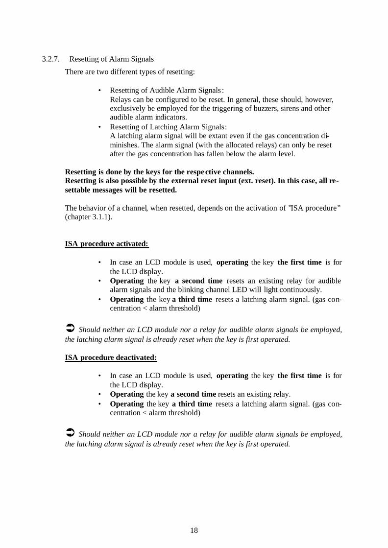
3.2.7. Resetting of Alarm Signals
There are two different types of resetting: • Resetting of Audible Alarm Signals :
Relays can be configured to be reset. In general, these should, however, exclusively be employed for the triggering of buzzers, sirens and other audible alarm indicators.
• Resetting of Latching Alarm Signals: A latching alarm signal will be extant even if the gas concentration di-minishes. The alarm signal (with the allocated relays) can only be reset after the gas concentration has fallen below the alarm level.
Resetting is done by the keys for the respective channels. Resetting is also possible by the external reset input (ext. reset). In this case, all re-settable messages will be resetted. The behavior of a channel, when resetted, depends on the activation of ”ISA procedure” (chapter 3.1.1).
ISA procedure activated: • In case an LCD module is used, operating the key the first time is for
the LCD display. • Operating the key a second time resets an existing relay for audible
alarm signals and the blinking channel LED will light continuously. • Operating the key a third time resets a latching alarm signal. (gas con-
centration < alarm threshold)
Ü Should neither an LCD module nor a relay for audible alarm signals be employed, the latching alarm signal is already reset when the key is first operated.
ISA procedure deactivated:
• In case an LCD module is used, operating the key the first time is for
the LCD display. • Operating the key a second time resets an existing relay. • Operating the key a third time resets a latching alarm signal. (gas con-
centration < alarm threshold)
Ü Should neither an LCD module nor a relay for audible alarm signals be employed, the latching alarm signal is already reset when the key is first operated.

19
3.3. Start-up Mode
Upon start-up or directly after voltage cut-off, alarm signals are blocked for 1 to 10 minutes (setting by software ConfigPro®). After the start-up mode, the system auto-matically enters into the operating status.
Ü As many transmitters signal undefined values after start-up, this mode eliminates any false alarms.
At the beginning of the start-up mode, functioning of the LEDs for system information can be checked. All four system LEDs are switched on for 0.5 s and those of the LED Modules for 2 s. The display of the LCD Module is built up line by line.
Display: LED Module: all green LEDs for ‘power’ and yellow LEDs for ‘fault’
flash System: LED for ‘maintenance’ flashes, maintenance relay is acti-
vated RBM/REM: - AAM: 2 mA LCD Module: display initialization and start-up signals Printer: cold reset, software version
If a mean value is configured for a given channel, it will only be determined from the mean values calculated within a preset number of minutes after the system has re-entered its operating status.
3.4. Maintenance Mode
This mode is for service and modification of the gas detection system.
For the various functions available in the maintenance mode, the rotary switch on the Controller Module has to be set to the respective position (switch positions 1-5). The number is indicated on the pertaining LED display (see chapter 7.1).
Channel Selection: After positioning of the rotary switch (except position 5 for PC communication), one or several channels can now successively be entered into a selected function for servicing by operating the respective key for more than two seconds. After the two seconds have elapsed, all LEDs for the relevant channel briefly light up. Only after releasing the key, the respective function is available. Completion of Servicing: Completion of servicing of the relevant channel will be effected if the respective key is operated once again (for more than two seconds) or the maximum time preset for servic-ing is exceeded (software ConfigPro®). With the switch on the controller module in position 0, the maintenance mode is ended and the unit is back to normal operation. The yellow LED for ‘maintenance’ switches off.

20
3.4.1. Alarm Suspension
Switch Position 1 The suspension of alarms prevents that relays which are related to alarms, faults, over- or under scale are not taken into account and are consequently not triggered. A general alarm suspension is possible as described in chapter 3.4.7.
Display: LED Module: yellow LED for ‘fault’ flashes, LEDs for alarm, fault, over
scale or under scale will flash if the transmitter signal complies with respective cond ition
System: LED for ‘maintenance’ is on and the respective relay is ac-tivated as soon as a channel is selected.
RBM/REM: all deactivated AAM: 2 mA or 0 V LCD Module: display of concentration: as in operating status, message: alarm suspension Printer: service relay activated
ATTENTION! - Previously activated relay outputs are reset when, after selecting alarm sus-
pension, conditions for triggering these relays are no longer given. - Alarm suspension must not be used for calibration purposes.
3.4.2. Operational Test
Switch Position 2 This operational test allows checking of channel LEDs, relay and analogue outputs. Ü The operational test simulates the triggering of all signals and alarms. After the op-erational test has been completed, any triggered alarm will be reset only if the meas-ured value is below the alarm threshold (including configured alarm hysterese).
Display: LED Module: yellow LED for ‘fault’ flashes, all other channel LEDs are
on System: LED for ‘maintenance’ is on and the respective relay is ac-
tivated as soon as a channel is selected RBM/REM: all activated AAM: latching in case of overrun (3.2.6): 22 mA, non- latching in
case of overrun: actual output of transmitter LCD-Module: latching in case of over scale (3.2.6):
display > end scale value, non- latching in case of over scale: display of concentration equals sensor output signal, message: operational test and other channel related sig-nals, e.g. alarms
Printer: service relay activated

21
3.4.3. Calibration
Switch Position 3 This function allows calibration and adjustment of transmitters. Outwardly, the system operates as it does with alarm suspension.
Display: LED Module: yellow LED for ‘fault’ flashes, LEDs for alarm, fault,
over- or under scale will flash, if the transmitter signal complies with respective condition
System: LED for ‘maintenance’ is on and the respective relay is ac-tivated as soon as a channel is selected
RBM/REM: all deactivated AAM: 2 mA or 0 V LCD Module: display of concentration: as in operating status
message: calibration Printer: service relay activated
3.4.4. Channel On/Off
Switch Position 4 Should a channel be deactivated, the measuring signal is no longer evaluated. Channel deactivation will be extant even after the maintenance mode is ended. The channel can be re-activated by renewed selection.
ATTENTION! - Even if the channel is switched off, the transmitter will be provided with 24V. For works to be carried out in hazardous areas, power to the transmitter must be disconnected. - For safety reasons, an alarm is internally signaled when deactivating a channel being in an AND or VOTING operation. The alarm will, however, not be shown on the LED Module. This evaluation may cause alarm signaling with an AND or VOTING operation of channels, even though this should not be the case according to the displays of the LED Modules.
Display: LED Module: all LEDs are off System: LED for ‘maintenance’ is on and the respective relay is ac-
tivated as soon as the rotary switch is set to position 4 and a channel had already been deactivated or after channel se-lection
RBM/REM: all deactivated AAM: 0 mA or 0 V LCD Module: no display available Printer: service relay activated

22
3.4.5. PC Communication
Switch Position 5 PC communication allows external access to the system MX62, e.g. for changing the configuration with software ConfigPro®. Measurement and evaluation are continued as long as no command via PC communication is given that requires quitting the measur-ing mode.
Ü During UPLOAD (see operating instructions of software ConfigPro®) of a changed system configuration, first of all an alarm for system error is triggered. After resetting, the system will be re-started with the changed configuration (see 3.3).
Display: LED Module: as operating status System: LED for ‘maintenance’ is on and respective relay is acti-
vated as soon as the PC is logged in RBM/REM: as operating status AAM: as operating status LCD Module: as operating status Printer: as with operating status
3.4.6. Ignore communication fault with relay modules
Switch Position 6 This function allows the replacement of a defective relay module during the normal op-eration mode without setting a system failure message. In normal operation mode a replacement of a defective relay module would cause a communication fault with relay modules and the system would have a system failure. If the rotary switch is in position 6, all communication errors with relay modules will be ignored for 30 minutes. The system will go into a system failure if the function is acti-vated longer than 30 minutes and a message will be displayed on the LCD module and/or the CM. To activate this function turn the rotary switch into position 6 and push the reset buttons of both controller. To deactivate this function turn the rotary switch into position 0 and push the reset but-tons of both controller. ATTENTION! The new relay module has to be of the same hardware type as the replaced. The re-placement e.g. of a RBM+REM by a RBM is not allowed and causes a system failure. Indication (during the 30 minutes)
LED Module according to normal operation mode System service LED is blinking +
the service relay is activated RBM/REM according to normal operation mode AAM according to normal operation mode LCD Module service mode Printer service relay activated

23
Indication (after the 30 minutes) LED Module all yellow fault LEDs are on System System failure LED is blinking System failure relay activated RBM/REM according to normal operation mode AAM according to normal operation mode LCD Module message system failure Printer Failure relay activated
Note: During replacement of the defective module disturbances on the output bus are possible, e.g. relays of other relay modules can be affected and switch.
3.4.7. General alarm suspension
The general alarm suspension is a special case of the channel depended alarm suspen-sion. If activated, all channels are in the operation mode “alarm suspension”, independ-ent of the position of the rotary switch at the CM. For activation of the general alarm suspension two analogue inputs (channels) are needed. The two channels have to be configured in a special manner by the software ConfigPro. The general alarm suspension is activated when both special configured channels have an alarm. The general alarm suspension is deactivated when both special configured channels have not an alarm. Configuration of the channels: A key switch with two independent contact pairs is needed. When not switched (position “0”), on both channels a signal current of 4 mA will be simulated using a 6k resistor. In the switched position (position “1”, general alarm suspension activated) at one chan-nel a signal current of 8 mA will be simulated using a 3k resistor and at the other chan-nel a signal current of 14 mA using a 1k7 resistor. ATTENTION! Only authorized and instructed persons are allowed to use the key switch. Note: It is not allowed to connect gas detectors to the channels for general alarm suspension.
3.5. Single Mode
In this mode, full redundancy is no longer given or comparison of the two controllers with each other is disturbed. Measurement will still be done correctly and all safety functions are maintained. In particular, switching of relay outputs is guaranteed. Since channel indication on the LED Modules and the LCD Module is linked to one of the two controllers, information will not be available if the respective controller is faulty (see 3.7 “Measures against Faults”)
24
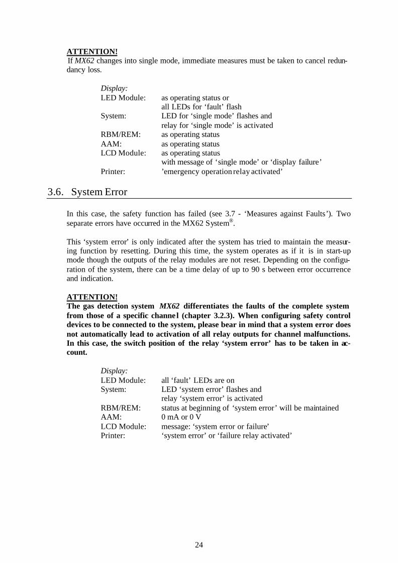
ATTENTION! If MX62 changes into single mode, immediate measures must be taken to cancel redun-dancy loss.
Display: LED Module: as operating status or all LEDs for ‘fault’ flash System: LED for ‘single mode’ flashes and relay for ‘single mode’ is activated RBM/REM: as operating status AAM: as operating status LCD Module: as operating status with message of ‘single mode’ or ‘display failure’ Printer: ’emergency operation relay activated’
3.6. System Error
In this case, the safety function has failed (see 3.7 - ‘Measures against Faults’). Two separate errors have occurred in the MX62 System®. This ‘system error’ is only indicated after the system has tried to maintain the measur-ing function by resetting. During this time, the system operates as if it is in start-up mode though the outputs of the relay modules are not reset. Depending on the configu-ration of the system, there can be a time delay of up to 90 s between error occurrence and indication.
ATTENTION! The gas detection system MX62 differentiates the faults of the complete system from those of a specific channe l (chapter 3.2.3). When configuring safety control devices to be connected to the system, please bear in mind that a system error does not automatically lead to activation of all relay outputs for channel malfunctions. In this case, the switch position of the relay ‘system error’ has to be taken in ac-count.
Display: LED Module: all ‘fault’ LEDs are on System: LED ‘system error’ flashes and relay ‘system error’ is activated RBM/REM: status at beginning of ‘system error’ will be maintained AAM: 0 mA or 0 V LCD Module: message: ‘system error or failure’ Printer: ‘system error’ or ‘failure relay activated’

25
3.7. Measures against Faults
Display: Possible Reason: Measures against Faults: LED ‘fault’ • Line disconnection
• Insulation defect • Defective transmitter • Wrong connected line • A transmitter signal has exceeded
24.5 mA. (Attention! Danger!)
• Measure signal current • Check connection • Check gas concentration sepa-
rately, e.g. with portable detec-tor Check transmitter and replace, if necessary
All ‘fault’ LEDs are on and LED ’system failure’ is blinking
• Timeout for ’Ignore communica-tion faults with relay modules’
• Turn the rotary switch into position 0 and reset both con-troller
Part of LEDs for ‘fault’ are on; no LED for system in-formation is on.
• An Analogue Input Module is defective or not connected.
• An Analogue Input Module is addressed wrong.
• Check connection between Analogue Input Module and Controller Module
• Check 24V power supply • Check address of Analogue
Input Module • Replace Analogue Input Mod-
ule • Check configuration with PC
software ConfigPro® • Check transmitter and replace,
if necessary
Display: Possible Reason: Measures against Faults: All LEDs for over- and un-der run of measuring range are blinking; the remaining LEDs for channel and system information are off.
• Communication error between Controller Module and display (In this case, safety functions are fully maintained by the relays.)
• Check connection between Controller Module and display
LED ‘single mode’ is blink-ing.
• Malfunction of controller B • Evaluate error code on the Controller Module
LED ‘single mode’ is blink-ing; all ‘fault’ LEDs are blinking.
• Malfunction of controller A • Evaluate error code on the Controller Module
LED ‘system error’ is blink-ing; all LEDs for ‘fault’ are on.
• Both controllers of the Controller Module are defective.
• Interruption of connection to all Analogue Input Modules
• Interruption of connection to at least one relay module
• Evaluate error codes on the Controller Module
• Check connection between Analogue Input Module and Controller Module
• Check connection between relay module and Controller Module
Analogue outputs: 0 mA or 0 V; channel ‘fault’ LEDs are off.
• Defective Analogue Output Mod-ule
• Interruption of connection be-tween Analogue Output Module and Controller Module
• Replace Analogue Output Module
• Check connection between Analogue Output Module and Controller Module
LED ‘battery’ is blinking. • Emergency power supplied • Check mains supply

26
All LEDs for ‘fault’ and ‘operation’ are blinking.
• Power failure logic in operation – no malfunction!
• After the preset time for power failure logic, the system auto-matically returns to normal op-eration.
Wrong indication of date/time after power failure
• Buffer battery on the controller module is exhausted (expected life time ≥ 10 years)
• Adjust setting via ConfigPro • Have battery replaced
Note: After rectifying system errors, a resetting of the micro controllers on the modules might be necessary. The Controller Modules should always be resetted at last. The reset keys are positioned on the modules (see chapter 7).
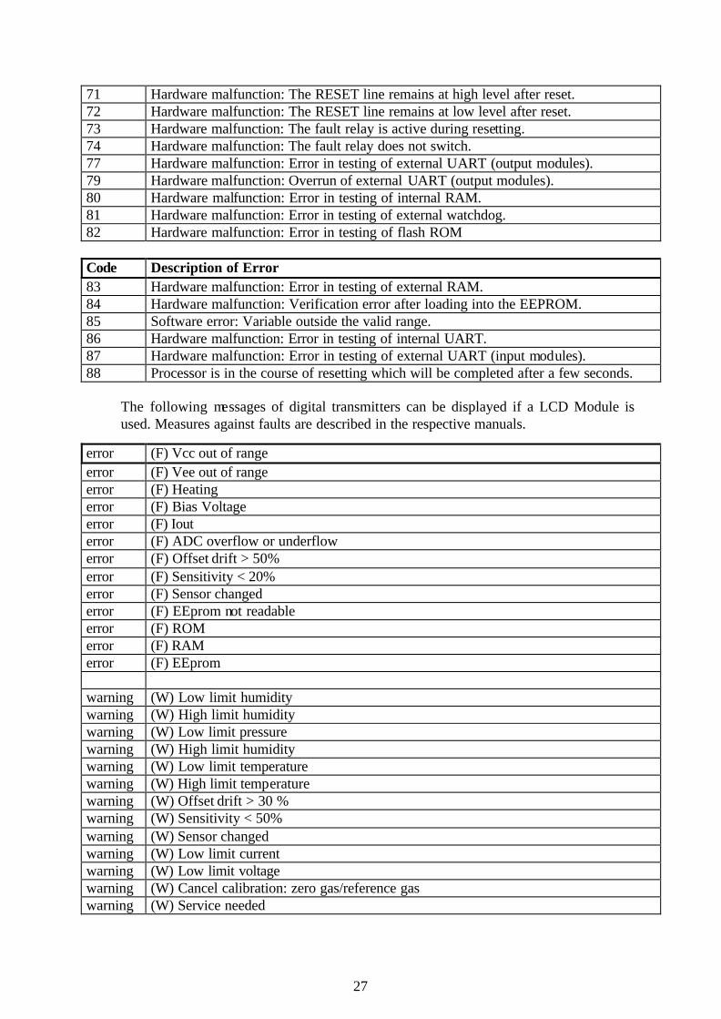
3.8. Error Codes of the Controller Module
The redundant controllers A and B in the Controller Module have both an LED display (status µC) for indication of error codes, assisting fast repair of any malfunction of the gas detection system by simplifying the search of errors within a limited range. Always of the first error recognized by the system is indicated. Only ‘error code 20’ can be overwritten by an error recognized later on.
Code Description of Error 3 Controller A (or B) has activated its fault release, the cause for it can however not be
determined. 4 DPRAM error
The status of Controller A (or B) cannot be read by the DPRAM. 10 The printer is offline. 11 No paper in the printer. 12 DATA LOGGER: Storing chip is filled to capacity. 20 (only CPU A)
Failure in LED Module addressing. Be sure that the number of connected LED Mod-ules is the same as the number of configured input modules (in groups of eight).
21 Error in automatic recognition of LED Modules: Recognized addresses are not con-secutive or incomplete.
40 No valid values in the parameter memory. 41 Checksum error in flash memory. 42 Incomplete upload. Not all parameters set have successfully been loaded or
initialized. 43 Incomplete configuration. No channels have been configured. 44 Error in loading or deleting the flash memory. 45 The system has not been activated. 46 The system could recognize several successive power failures. 47 The Controller has received instruction for RESET from the RS232 interface. 48 Error in configuration of input modules: e.g. Loop Module has an even address 60 The running time of the program (loop time) has been exceeded repeatedly. 61 Error in communication with the Analogue Input Module. The measured values cannot
be read within the preset short period of time. 62 Error in memorizing measured values. No module can memorize any measured va lues. 63 Communication error with one or several relay modules. 64 Configuration error: Please check configuration of relay modules. 70 Hardware malfunction: The READY line remains at high level after reset.
27
71 Hardware malfunction: The RESET line remains at high level after reset. 72 Hardware malfunction: The RESET line remains at low level after reset. 73 Hardware malfunction: The fault relay is active during resetting. 74 Hardware malfunction: The fault relay does not switch. 77 Hardware malfunction: Error in testing of external UART (output modules). 79 Hardware malfunction: Overrun of external UART (output modules). 80 Hardware malfunction: Error in testing of internal RAM. 81 Hardware malfunction: Error in testing of external watchdog. 82 Hardware malfunction: Error in testing of flash ROM
Code Description of Error 83 Hardware malfunction: Error in testing of external RAM. 84 Hardware malfunction: Verification error after loading into the EEPROM. 85 Software error: Variable outside the valid range. 86 Hardware malfunction: Error in testing of internal UART. 87 Hardware malfunction: Error in testing of external UART (input modules). 88 Processor is in the course of resetting which will be completed after a few seconds.
The following messages of digital transmitters can be displayed if a LCD Module is used. Measures against faults are described in the respective manuals.
error (F) Vcc out of range error (F) Vee out of range error (F) Heating error (F) Bias Voltage error (F) Iout error (F) ADC overflow or underflow error (F) Offset drift > 50% error (F) Sensitivity < 20% error (F) Sensor changed error (F) EEprom not readable error (F) ROM error (F) RAM error (F) EEprom warning (W) Low limit humidity warning (W) High limit humidity warning (W) Low limit pressure warning (W) High limit humidity warning (W) Low limit temperature warning (W) High limit temperature warning (W) Offset drift > 30 % warning (W) Sensitivity < 50% warning (W) Sensor changed warning (W) Low limit current warning (W) Low limit voltage warning (W) Cancel calibration: zero gas/reference gas warning (W) Service needed

28
3.9. Overview of LED Indications
The following tables show the various possibilities of indication by the LED Modules and the LEDs for system information. Besides the channel status, information on the system status can also be signaled in case of malfunction.
ATTENTION! The tables below show the possibilities of indication when the ISA procedure is de-activated. For detailed information see chapter 3.1.1 “ISA procedure” (slow blink-ing channel LED).
Channel-related Indications LEDs Standard Channel
selected (LCD)
Alarm suspension
Calibration Functional Test
Power Failure Logic
Over scale on/off on/off/blinking off/blinking off/blinking on off Alarm 3 on/off on/off/blinking off/blinking off/blinking on off Alarm 2 on/off on/off/blinking off/blinking off/blinking on off Alarm 1 on/off on/off/blinking off/blinking off/blinking on off Under scale on/off on/off/blinking off/blinking off/blinking on off Fault on/off on/off/blinking blinking blinking blinking blinking Power on blinking on on on blinking Single Mode
off off off off off off
System Error
off off off off off off
Service off off blinking blinking blinking blinking Battery blinking/off blinking/off blinking/off blinking/off blinking/off blinking/off
System-related Indications LEDs Communication
Error (*1) Error in LEDM Addressing (*4)
(Error Code 20)
Single Mode µCA: ok µCB: error
Single Mode µCA: error (*2) µCB: ok
System Error
µCA: error µCB: error
Over scale all blinking all blinking on/off/blinking off off Alarm 3 off off on/off/blinking off off Alarm 2 off off on/off/blinking off off Alarm 1 off all blinking on/off/blinking off off Under scale all blinking all blinking on/off/blinking off off Fault off off on/off/blinking all blinking (*3) all on (*3) Power off off on/off/blinking off off Single Mode
off blinking/off blinking blinking off
System Error
off blinking/off off off blinking
Service off blinking/off off off off Battery off blinking/off blinking/off blinking/off blinking/off
(*1) The LED Modules do not receive any data from the Controller Module (Controller A). (*2) In this single mode, LED Modules do not receive any information on status of channels.
The safety function of the system is, however, fully maintained. (*3) The respective LEDs of all channels on the LED Module are activated, i.e. including channels
not used or deactivated. (*4) This error code is exclusively indicated on CPU A (the fault relay will not be activated). Be sure that the number of connected LED Modules is identical with the number of input channels. The
number of connected LED Modules must not be more or less.

29
4. Operating of the LCD Module
The optional LCD Module (240 x 128 pixels) is operated by its four keys as well as those for the respective channels. Besides display of the individual channels indicating information on measuring points and system events, menu-driven operation allows call-ing up of all settings and information plus controlling of data logger and printer.
4.1. Display of Channels
Normal operation: • The logo is displayed. By operating a key of any channel, the respective
channel information is shown for 60 minutes - indicating information of measuring point, system parameters as well as events. Afterwards, the display returns to the logo automatically.
• When operating an arrow key during channel display, the fo llowing channel is indicated next to the one currently shown.
• By the menu item for LCD settings (see following chapter), two different displays can be selected:
- After operating an arrow key while the logo is displayed, all channels will successively be switched through their full range in rising order, i.e. the display of each channel changes every 5 seconds. After all channels have been shown, the display returns to the logo.
- Alternatively, constant scrolling of the display for all activated chan-nels can be set by the menu.
Alarm: • In case of alarm, the respective channel is automatically displayed. If
several channels are affected, these will automatically be scrolled through.
• While alarm for one or more channels is indicated, any channel can be displayed by constant operation of the respective key. As soon as it is re-leased, alarm for the channel(s) is once more indicated.
• Any system events are indicated while the logo is displayed.
4.2. Menu
By operating the keys OK or ESC while the logo of is displayed, the main menu is en-tered in which various settings can be modified or information be obtained. While the unit is in service mode, i.e. during PC communication, values can only be read and not changed. The menu is left 60 seconds after the last operation automatically and the display re-turns to the logo.

30
Generally, the following applies for any operation of the menu:
- OK key: for going one menu level lower or
acknowledgement of entry and modification respectively - ESC key: for going one menu level higher or
rejection of entry and modification respectively. - Arrow keys: for scrolling within a menu or change of va lues
4.2.1. System / LED-Test
The LEDs of all LED panels are activated by this menu item.
4.2.2. System / System Status
The current system status is indicated.
4.2.3. System / System Information
Indication of system information such as: - actual software version - order number - serial number - next date of maintenance - etc.
4.2.4. Channel Information / Current Information
After the respective channel has been selected with the aid of the arrow keys, current channel information is displayed. This menu corresponds with operating the key for any channel during normal operation (see 4.1 Display of Channels).
4.2.5. Channel Information / Display of Configuration
After selecting the respective channel with the aid of the arrow keys, the actual status of the channel (activated, deactivated etc.) as well as the actual channel configuration is displayed.
4.2.6. Relays
The respective relay is selected by the arrow keys. For selection, only configured relays are taken into consideration and displayed. After selection of a relay, its configuration is indicated.
4.2.7. Analogue Outputs
The respective analogue output is selected by the arrow keys. For selection, only con-figured analogue outputs are taken into consideration and displayed. After selection of an analogue output, its configuration and actual value are indicated.
4.2.8. Data Logger / Set-up
After selection of the respective channel, data recording for this channel can be config-ured.
The modes ’8-hour mean value’ as well as ’recording’ can be activated or deactivated. With ’recording’ being activated, the ‘recording mode’ may also be set.

31
With continuous recording, the measured values of the selected channel are constantly stored. With event recording, only events of the respective channel are recorded.
Note:
Modifications for recording of a channel can only be effected if the rotary switch on the controller module is not in position “5” (PC communication).
4.2.9. Data Logger / Histogram
After selecting the respective channel by the arrow keys, the histogram of the channel is displayed. By means of this histogram, gas concentrations can be monitored over a longer period of time. To see the concentration prevalent at a certain time, a cross is moved to the respective position with the aid of the arrow keys. This cross is found on the X-axis. The gas con-centration measured as well as any active alarm signal at the time is shown in the upper margin of the LCD. By operating the OK key, the histogram can be deleted. Recording intervals may be set in the menu “Data Logger” of the configuration software ConfigPro®.
4.2.10. Data Logger / Events
At first, general information on events is shown such as number of all events from be-ginning of the recording, start of recording, date of latest event, etc.
In addition, a menu is displayed for selecting the next step:
- Show events:
All events are shown in chronological and declining order, i.e. the most recent events come first. The channels are indicated on the LED Module according to their con-figuration, e.g. A03 means “rack A, channel 3”. As to the display of relays, first the module address and then the relay number is shown, e.g. M8 R3 means “relay module 8, relay No. 3”.
- Delete events: In this menu item, all stored events are deleted.
4.2.11. Data Logger / 8-Hour Mean Values
After selecting the respective channel with the aid of the arrow keys, stored mean val-ues are shown.
For this, however, the recording of mean values need to be activated for the respective channel by the configuration software ConfigPro®.

32
4.2.12. Data Logger / Format
On the one hand, this menu item can be used to format the memory card. On the other hand, general information of the memory card is shown.
4.2.13. Printer Settings
The printer can be activated or deactivated. Note: Activation or deactivation of the printer can only be effected if the rotary switch on the controller module is not in position “5” (PC communication).
4.2.14. LCD Settings
LCD settings can be modified by this menu item. For this, the entry to be modified is selected by the arrow keys, after which the OK key is operated. Language: The menu language of the LCD can be selected. Options: English, German, French, Spanish and Dutch. ATTENTION! Changing the language only refers to the menu structure. Designations regarding channel information such as measuring point description, target gas etc. are not af-fected. Such designations can only be changed with the aid of the configuration software ConfigPro®. Contrast: By the arrow keys, contrast can be increased or decreased. Scroll Mode: As already mentioned in chapter 4.1, Display of Channels, operation of the key arrows allows the actual measured values of all configured and activated channels to be auto-matically shown for approx. 5 seconds while the company logo is displayed. This parameter can change the scroll mode. Off: The channels are not scrolled through. Once: All configured and activated channels are scrolled through once. When the last channel has been shown, the company logo will be displayed again. Continuous: All configured and activated channels are continuously shown.
Background Light: This parameter determines when the display is to be backlit. Constant: The background light of the display is always activa ted.

33
Pressing of Keys: The background light of the display is only switched on when a key is pressed. It makes no difference whether a key of the LCD Module or a key for a respective channel is op-erated.
Events: The background light of the display will be activated if any event occurs. This includes alarms and operating the keys of the LCD Module or those for a respective channel. Rate of Repetition: If the ESC key is operated while a system event is shown, the display will return to the company logo. After a certain period of time, the display changes back to the system event in case the fault is still prevailing. This period of time can be set with this parameter. LCD Copy number: For determination of the LCD Copy Module address for the LCD Copy Filter see chap-ter 2.1.10 “LCD Copy Module”. Each LCD Module has automatically the address “0”. Changing the address of an LCD Module has no consequences. The structure of the menu is shown on the following page.

34
Menu for LCD module
System
LED test (for LED modules)
System status
System information
Channel information (selection of channel)
Current values
Configuration data
Relay information (selection of channel)
Information on analogue outputs (selection of channel)
Data logger
Set-up (selection of channel)
8-hour mean value (on/off)
Data recording (on/off)
Mode (at events/continuous)
Display of histogram (selection of channel)
Display of events
Read events
Delete events
Display of 8-hour mean value (selection of channel)
Format memory card
Delete card
Complete data
Printer (on/off)
LCD settings
Language (English, German, ...)
Contrast (-9 to +9)
Scroll mode (off, once, continuous)
Background light (constant, during entries, at events)
Rate of repetition (1 to 59 mins)
35
5. Maintenance
Maintenance of gas detection systems includes inspection, servicing, calibration and ad-justment. EN 50073 and EN 45544-41 give respective instructions. Inspection and servicing by specialists comprise verification of keys, LCD display and relay contacts as well as operational check of alarm thresholds with test gas to ensure correct triggering of alarms plus calibration and adjustment of transmitters. These main-tenance works should be carried out during initial operation and in half-yearly intervals. Calibration and adjustment of the transmitters means verification of the zero point with the help of zero gas as well as of sensitivity and response time with test gas includ-ing corrective adjus tment, if necessary. Intervals of calibration and adjustment can be shorter than intervals of inspection and maintenance. When fixing these intervals, specifications given in the operating instruc-tions for the transmitters connected to MX62 are to be followed.
Ü National regulations may exist that include rules of maintenance for special appli-cations. In Germany, for example, regulations BGI 518 and BGI 836 of the Employers’ Liability Insurance Association are to be observed.2
5.1. Calibration and Adjustment
The system MX62 provides four different methods of calibration that depend on the transmitter to be calibrated as well as the prevailing conditions on site.
5.1.1. Direct Calibration at the Transmitter
Transmitters with a standardized output of 4-20 mA are directly adjusted with, for ex-ample, the aid of potentiometers fitted inside the transmitters. This calibration is carried out with the function for calibration of the maintenance mode to avoid triggering of re-lays.
____________
1 EN 50073: Regulation for selection, installation, employment and maintenance of units for detection and measuring of combustible gases or oxygen EN 45544-4: Electric units for detection and direct measuring of concentration of toxic gases and vapors – Part 4: Regulation for selection, installation, employment and maintenance
2 BGI 518: Gas detection systems for protection against explosion – Employment and operation
BGI 836: Gas detection systems for toxic gases/vapors and oxygen – Employment and operation
For optimum and safe execution of servicing, we recommend concluding a maintenance contract with us. This will allow your system to be serviced by our qualified engineers at the required intervals and will provide maximum safety.

36
5.1.2. Remote Calibration for Standard Transmitter
It is possible to adjust standard 4-20 mA transmitters without actually accessing the transmitter directly. This remote calibration can be carried out in the maintenance mode of “PC Communication” by adjusting the 4-20 mA output of the MX62 within a preset range by means of special PC software RemoteCalibrationPro. ATTENTION! Since evaluation of the 4-20 mA input signal is altered, the signal of 4-20 mA needs to be reset in case the transmitter is replaced or directly calibrated. This is achieved by the function for calibration of the maintenance mode.
5.1.3. Manual and Automatic Field Adjustment of Digital Transmitter TBGW EX
The digital transmitters by, e.g. TBGW EX, have a 4-20 mA analogue as well as a RS485 connection to the MX62 System®. The latter serves for transmission of addi-tional data during normal operation as well as for adjustment. Adjustment is detailed in the operating instructions for digital transmitters and carried out with the help of soft-ware ConfigEx®.
5.2. Transmitters
For calibration and adjustment, specifications laid down in the operating instructions for the transmitters have additionally to be observed. This refers especially to the selection of test gases. In general, the concentration of the test gas must be above alarm level 2 and below the end scale value.
6. Technical Data Power Supply: 230 V AC, 50 Hz or 24 V DC
(permissible range: 19.2 to 27.6 V) Power Consumption: the number of modules and input requirement of trans-
mitters determine power consumption Maximum Input: 64 transmitters (e.g. 8 Analogue Input Modules with 8
inputs each) Input Signal: standardized 4-20 mA interface
(3- and 2-wire technique) as well as RS485 connection The input load is dependent on current:
Rin=200O + 4300/ImA Input Load: Analogue Output 4-20 mA 450 O at maximum Voltage Output 0-10 V 100 kO at minimum

37
Input Requirement for Transmitters: 24 V DC (regulated power supply)
Maximum Current Load per Transmitter: 3.5 VA, 150 mA
Signal Evaluation: two 16-bit micro controllers working in parallel with a maximum cycle time of Tz < 100 ms
PC Interface: RS232
Printer Output: Centronics interface
Display: seven LEDs for channel information of each channel; optional LCD display (240 x 128 pixels)
Data Logger: 64 MB
Maximum of Relays: 128 freely programmable relays with change-over con-tacts for 250 V AC, 6 A resistive load (8 relay modules with up to 16 relays)
Operation: one key per channel as well as four keys for the optional LCD Module
Temperature Range: 0 to + 55 °C
Storage Temperature: - 25 to + 60 °C (for unit, accessories, spares)
Humidity: 5% to 90% rH
Ambient Pressure: 80 to 120 kPa
Drift at Input: < 0.1% of end scale value per month
Deviation between Analogue Output and Displayed Value: < 2.5% of end scale value
Vibratory Fatigue Limit: 10 to 55 Hz (at maximum amplitude of A = 0.15 mm) Installation of relay modules has to be vibration-free to avoid any oscillation of switching contacts (false alarm).
Installation: wall-mounted housing, 19"-rack with mounting plate, control panel with mounting plate
Wall-mounted Housing: Material: sheet steel / 1.5 mm, powder-coated, RAL 7032 Size: depending on number of modules Enclosure Rating: IP 40 and, optionally, IP 54 Please see relevant data sheets for technical details of respective transmitters.

38
7. Terminal Connections, Jumpers and Rotary Switch
7.1. Controller Module (CM)
The CM, consisting of two PCBs, is fitted with relays for indication of maintenance mode (make contact), single mode (make contact) as well as system error (break con-tact). The relays are only provided for signals of up to 30 V DC, 0.1 A. The rotary switch allows setting of the various functions for servicing (see 3.4. “Main-tenance Mode”). At the External Reset Input all relevant relays and latching alarms can be reset with an external key connected. In case no emergency power is supplied (with a 24 V signal), a bridge connection be-tween the 24 V inputs has to be made.
Single M.
External Reset
LED
µCAError
LED
µCBError
LEDService
Output Module
LED
Display ofRotary Switch
with basic PCBand additionalplugged PCB
RS-232 (PC) Centronics(printer)Display
Reset
Controller Module
µC B
StatusµC B
Analog Input Modules
Display
Rotary Switchfor Servicing
OutputA
OutputB
Mode
System-failure
Service
Single
µC A
EPS Signal or +24 V
+24VGND
Reset
StatusµC A

39
7.2. Analogue Input Module (AEM)
Different addresses between 1 and 8 are to be allocated to the AEMs with help of the fitted rotary switch. Five terminals each are available for all eight input channels:
• 24 V Power Input requirement of the transmitter • GND Connection to ground (not required for 2-wire
connections) • Sig. 4-20 mA signal from transmitter • A Line A of RS485 connection • B Line B of RS485 connection
Module size: 160 x 90 x 50 mm
A
GND
Addresses from 1 to 8 for the AEM
ASig.
24V24V24V24 VGNDGND
1
B BA
Sig. Sig.
24V 24VGND GND
32
A A A
GND
Power Supply
5
Sig.
6 7
24V 24VGND
Sig. Sig.
B B B
B BA
Sig.
24VGND
4
A
8
24V 24VGND
Sig.
B

40
7.3. Analogue Input Extension Module (AEAM)
The AEAM needs to have the same address as the respective AEM. The smoke detector has to be connected to the AEM, excepting the 24 V supply. The connection of the 24 V supply has to be done on the AEAM. Therefore the terminals 24 V of the AEM and AEAM are connected. Each of the 8 channels has two connectors
• 24 V in Supply for the Smoke Detector (from AEM) • 24 V out Supply for the Smoke Detector (to the detector)
24V in
24 V
24V out
GND
1
5
Adresses from 1-8 for theAEAM
432
6 7 8
24V in24V out
24V in
24V out24V in
24V out
24V in24V out
24V in24V out
24V in24V out
24V in
24V out
Supply
Module size: 160 x 70 x 50 mm

41
7.4. Basic Relay Module (RBM) and Extension Relay Module
(REM)
Different addresses between 1 and 8 have to be allocated to the relay modules with help of the fitted rotary switch. The REM with relays 9 to 16 is plugged onto the RBM with relays 1 to 8. All 16 relays have a change-over contact (make contact, input, break contact). Each relay has a pertaining jumper by which closed or open circuit operation can be se-lected (see 2.1.4).
• upper position (R) => closed circuit operation • lower position (A) => open circuit operation
The last output module has to form a bus end for both signal buses with two jumpers (see Analogue Output Module).
• left position => end of bus • right position => further output modules
Module size: 190 x 90 x 75 mm
NO
13Relay
1
NO
3
NO
2
NCNO
1
NC NC NONCNO
4 5
NC
6
.
9Relay
REM
10 11 12Relay Relay Relay
NC NCNO NO
7
NC
Reset Buttonfor the twoRelay ModuleControllers
of BusRBMEnd
-A
2-
B2
++
A1B
1+2
4V-
Addresses from 1-8 for the RBM
Open Circuit OperationJumper in position of
Relay
1514 16Relay Relay

42
7.5. Loop Module (LOOPM)
The address of the LOOPM has to be allocated with help of the fitted rotary switch. Possible addresses for loop modules are 1, 3, 5 and 7. In case of a wrong address (even numbers), the loop module activates its LED for ‘error’. The last module of the output bus has to form a bus end with two jumpers . Contrary to the other modules on the output bus, the loop module has two jumpers J1 and J2 with only two contacts each.
• J1 & J2 closed => terminated output bus • J1 & J2 open => non-terminated output bus
The jumper J3 is not used as its position does not affect the function of the module.
Output Bus (8 Wires)2x(24V,GND,A,B)A/B Twisted Pair
8
Inpu
t 24V
Sup
ply
LOO
P
Out
put 2
4V S
uppl
y LO
OP
(max
. 800
m)
Out
put A
/B R
S48
5 LO
OP
(max
. 800
m)
Inpu
t A/B
RS
485
LOO
P
Inpu
t 24V
Sup
ply
LOO
PM
Con
nect
or fo
r up
to2
Ana
log-
Inpu
t-Mod
ules
(AEM
)
LOOPM
- IN + B IN A - PM + + B2 A2 -- + OUT - + B OUT A + B1 A1 -
PLA PLB EUA EUB AEM1 AEM2
RLB RLA RMB RMA
REA
REB
ResistorsEnd-Of-Line-
(Output Bus)J1 J2
J3
OH WI
LOOPM Address
Reset button
Module size: 167 x 90 x 85 mm

43
7.6. Analogue Output Module (AAM)
Different addresses between 1 and 8 have to be allocated to the AAMs with the help of the fitted rotary switch. Each relay has a pertaining jumper by which 0-10 V or 4-20 mA can be selected.
• left position => 0–10 V • right position => 4–20 mA
The last output module (whether it is a relay or analogue output module) has to form a bus end for both signal buses (redundancy). This is done with the two jumpers on the upper right-hand side.
• left position => end of bus • right position => further output modules
Module size: 160 x 90 x 50 mm
4-20mAGND
2
Addresses from 1-8for the AAM
Power Supply
GND24V
21
GND0-10V
3
1
4
4-20 mAJumper
Jumper0-10 V
AAM-µC1
Analog Outputs
3 4
5 6
5 6
7
7 8
8
AAM-µC2
1 2
End of Bus

44
7.7. LCD Module / LCD Copy Module
The LCD Module with integrated data logger can accommodate a storing chip of 64 MB memorizing measured values, alarms and system events as well as 8-hour mean values. All information stored can be shown on the LCD screen. The recorded values are shown on the LCD in form of a histogram. If the LCD Module/LCD Copy Module is the last module to be operated on the display bus, the bus will have to be terminated on the Module with the bus end jumper J1:
• J1 open => further display modules • J1 closed=> bus end
Background lighting and contrast can be set via potentiometers.
Power Supply
Background
Insertionfor StoringChip
+24VGND
RS-485
- A B +
IN OUT
Lighting
MMC-OUT
PC Interface
ContrastControl
OUT
IN
J1

45
7.8. MIMIC Module
The address of the copied LED Module has to be set with the address select switch at the MIMIC Module. The switch is on the main PCB of the MIMIC Module. The maximum current of the OC outputs of the MIMIC Module is 200mA. For connection of external LED a 24V supply is needed.
GND24V
+BA-
24Vch824Vch724Vch624Vch524Vch424Vch324Vch224Vch1
24 V Power Supply
RS 485 Bus
Test button
Reset buttonDisplay busoutput
Wire wrap connectors for single LED`s
Display businput
LED Moduleconnector
Module size: 160 x 71 x 128 mm

46
8. Connection and Installation
8.1. Wiring
8.1.1. Mains Supply
The electric installation for MX62 has to provide an isolator (e.g. an overload release) to guarantee secure disconnection from the mains supply. MX62 must not be installed in hazardous areas. MX62 is designed for stationary installation to a mains supply of 230 V AC/50 Hz (also available for 24 V DC). The unit complies with Protection Class I according to EN 60335 and has to be connected to a protective conductor (PE).
8.1.2. Connection of Relays
A maximum of 128 relays (8 relay modules with up to 16 relays) with potential- free change-over contacts for 230 V/6 A resistive load can activate external devices or transmit information. Selection of closed or open circuit operation is done by a jumper. Unshielded cables can be used for connection. The relay modules can be connected through a flat or bus cable. The maximum bus length is 800 m. Installation of the relay modules must not be subject to any oscillation, the impact of which could cause short-term false signals at the relay outputs.
8.1.3. Connection of Transmitters
The gas detection system is designed for connection of up to 64 transmitters (4-20 mA) by 2- or 3-wire technique. Connecting of the transmitters to the Analogue Input Mod-ules is via shielded cable. Transmitters with external input requirement must not be connected. The sheath of the shielded line must be connected with the housing of MX62. In case the housing of the transmitter is made of metal, the sheath is also to be connected with this housing via the screwing. The maximum cable length is determined by the transmitter to be connected (see re-spective data sheet) and must not be exceeded.
8.2. Installation of MX62
Attention! Make sure power supply is cut off prior to
opening the unit.
8.2.1. Wall-mounted Housing
The size of the wall-mounted housing depends on the number of modules. Attention is to be paid to free accessibility. Safety systems should always be installed at a distance from any devices with high generic emission.

47
8.2.2. 19"-Rack
The distance between the 19"-rack and the mounting plate must be less than three me-ters. The sheath of the shielded line should be connected with the housing at the entry of the switchboard cabinet and on the mounting plate. The relay modules and LED Mod-ules can be connected by a flat or bus cable. The maximum bus length is 800 m.
8.2.3. Control Panel
The distance between Controller Module and mounting plate must be less than three meters. The sheath of the shielded line must be connected with the housing on the mounting plate. The relay modules and LED Modules can be connected by a flat or bus cable. The maximum bus length is 800 m.
9. Cut-out for Control Panel Installation The cut-out and bores apply to all three front panels (LED, LCD and LOGO front panels).
208,30 mm
215,00 mm
122,
50 m
m
109,
00 m
m
86,35 mm
bore (3,5 mm)
The front panels have a total size of 243 x 149 mm. The front panels project from the cut-out at top and bottom by 20 mm, left and right by 14 mm.

48
10. Accessories and Spare Parts
Optional Accessories: Order No.
Software VisualPro® for visualization of several linked MX62 units
31550
Software ConfigPro® for parameter settings of MX62 31500 Flashing Luminous Transparency 230 V AC
67040
Flashing Alarm Light 230 V AC
67160
Super tone Horn 108 dB/m (A) 230 V AC
67010
Spare Parts:
Analogue Input Set (AES 8) 31140 Basic Relay Module (RBM 8) 31150 Extension Relay Module (REM 8) 31160 Analogue Output Module (AAM 8) 31130 LCD-Copy Module Set for 19”-Rack 31445
Please ask or your local distributor for further accessories and spare parts.
11. Certificates
11.1. CE Accreditation
MX62 complies with the basic safety requirements of the following European directives. EMC Directive 89/336/EWG: The unit has passed EMC testing according to EN 50081-1 and EN 50270 and can be employed in domestic and industrial areas in view of generic emission and immunity. Low Voltage Directive 73/23/EWG: The system is in compliance with EN 61010-1 Part 1, Safety regulations for electric measuring, control and laboratory equipment. ATEX Directive 94/9/EG: The gas detection system is approved for measurements in explosive areas using suit-able transmitters such as TBGW EX: EC-type examination certificate BVS 03 ATEX G 002 X For further details please refer to the ‘EC Declaration of Conformity’ and chapters 11.2 and 11.3.

49
11.2. Metrological Approvals
MX62 is approved by EXAM BBG Prüf- und Zertifizier GmbH, Bochum, according to EN 61779-1, EN 61779-4 and EN61779-5 (combustible gases), EN 50104 (oxygen) and EN 45544-1 with EN 45544-2 (toxic gases) and EN 50271 (digital technique).
Certificate No. 41300402 Metrological approval included the following measuring ranges: - 0 – 20% LEL - 0 – 100% LEL - 0 – 100 %vol. CH4
- 0 – 100 %vol. CO2
- 0 – 10 %vol. O2
- 21 – 0 %vol. O2
- 0 – 25 %vol. O2
- 0 – 1000 ppm NH3
- 0 – 300 ppm CO; MBU/NA:1 1.2/2.4 ppm CO - 0 – 500 ppm CO; MBU/NA: 2/4 ppm CO - 0 – 3000 ppm CO2; MBU/NA: 20/25 ppm CO2 - 0 – 5 %vol. CO2; MBU/NA: 0.02/0.04 %vol. CO2 - 0 – 50 ppm H2S; MBU/NA: 0.2/0.4 ppm H2S - 0 – 100 ppm H2S; MBU/NA: 0.4/0.8 ppm H2S
Testing did not include the following functions described in these operating instruc-tions:
• Data logger of LCD Module (chapter 2.1.7) • Calibration of 4-20 mA input of standard transmitters (chapters 3.4.3 and 5.1.2) • Manual and automatic field adjustment of digital transmitter (chapter 5.1.3) • LCD Copy Module (chapter 7.7) • “ADVANCED” relay (see manual “ConfigPro”) • MIMIC Module (chapter 7.8) • Analogue Input Extension Module AEAM (chapter 2.1.9)
The metrological approval will only be valid if the gas detection system is used together with transmitters having the same approval.
1 MBU/NA: Minimum end scale value and zero drift according to EN 45544. When connect-ing a transmitter, its respective values have to be observed. In case of combination, the higher value is valid.

50
11.3. Special Conditions for Safe Operation
• The control unit has to be operated in a way that one relay output must be configured as collective relay for all channel malfunctions.
• The outputs for measured values are to be operated as current outputs. • Installation of the relay modules must not be subject to any oscillation,
the impact of which could cause short-term false signals at the relay out-puts.
• Please note that when employing the gas detection unit at very low con-centrations of the target gas, measurement uncertainty is higher than 50% for the ranges of 0-5 %vol. CO2 and 0-100 ppm H2S.
• Indication on the LCD display must not be used for any safety control purposes.
• Alarm 3 must be configured to be latching when measuring combustible gases or oxygen.
• If a remote sensor with internal relays is used, it has to be ensured that a failure of data transmission to the remote sensor is unambiguously sig-naled. For this purpose a relay output of a relay module has to be config-ured in a way that a failure of data transmission and the subsequent loss of function of the transmitter relay are signaled. If more than one trans-mitter with internal relays is connected, this signal may be configured as a common signal.
• The operation of a Loop Module with transmitters of different type via the digital interface has to be certified by a separate supplement to the EC-type examination certificate.

51
12. Annex A: EC-Declaration of Conformity

52
13. Annex B: Translation of Data Logger Messages In the German version of the operation instructions for MX62 this chapter contains the german translations for the Data Logger Messages which are in English language originally. 14. Annex C: Planning Aid: Functional Safety for MX62
14.1. Introduction
This document is a planning aid for any MX62 system to be employed as part of a safety control installation. Extracts of this document will also be integrated into the operating instructions of Gas Detection System MX62 (version 2.2 and higher).
14.2. MX62 as a part of safety control installations in compliance with
directive EN 61508
The system MX62 is designed for safety control installations complying with require-ments of directive EN 61508 up to SIL 3 inclusive. Classification is based on directive DIN EN 50402 as specific standard for gas detection systems in addition to the afore-mentioned basic standard. This document gives planning aid for integration of MX62 in a safety control installa-tion:
- Definition of safety-related functions to be effected by MX62 - Definition of testing cycle for safety-related functions - Requirements for the configuration of MX62 - Probability of failure on demand (PFD) of MX62 for total failure assess-
ment of the superior system in compliance with directive EN 61508
Note: This planning aid only refers to aspects relevant to the avoidance or control of failures affecting regular system functions. Measuring during undisturbed operation is not taken into account. For this please refer to the respective notes in the operating instructions of MX62 and of transmitters connected to it.

53
14.3. Definition of safety-related functions to be effected by MX62
Integrated into a safety control installation, the gas detection system MX62 is a link of the chain, forming the overall safety structure. The safety-related function of MX62 be-gins at the channel input of the Analogue Input Module and ends at the relay output of the gas detection system.
MX62 provides the following outputs:
- safety-relevant outputs: o Relay for system failure o Relay outputs (Basic Relay Module and Extension Relay Module)
- non-safety-relevant outputs: o Outputs for visual indication (LED, LCD and Logo Modules) o Analogue outputs for measured values (Analogue Output Module) o Relays to indicate emergency operation and maintenance mode
The chain of measurement processing always includes Analogue Input Modules, the Controller Module and data transmission.
Requirements for the safety-related functions of MX62 follow the overall configuration of a safety control installation. In addition, any legal or locally applicable regulations need to be observed.
Example: Requirements for functional safety of a relay output triggering a visual alarm on a con-trol panel only are generally lower than those for a relay output activating emergency shutdown of the system.
14.4. Requirements for the configuration of MX62
• Directive DIN EN 50402 provides that a Safety Integrity Level (SIL) is allocated to each safety-related function of a gas detection system in conformity with the respective SIL laid down in directive EN 61508.
The central functions of MX62 which refer to the Controller Module and its operations are designed to correspond with the requirements of Safety Integrity Level 3.
Different levels only apply to the inputs (transmitters, Analogue Input Module) and the various outputs. Table 1 lists the requirements for configuration of the hard- and soft-ware in accordance with the varying Safety Integrity Levels.
Since visual indications are not integrated into the chain of safety control and will there-fore not have any impact on the chain of safety control of MX62, these will not be taken into account for configuration requirements.
ATTENTION! ADVANCED logic operations (see operating instructions ConfigPro) for the triggering of relay outputs are not metrological approved. Consequently, ADVANCED logic op-erations must not be employed for safety-relevant purposes.

54
When configuring MX62, please observe that each connected transmitter is monitored for any short circuit or interruption of power supply which will then trigger a fault alarm. Note: If two or more transmitters are to monitor the same area, it will have to be made sure that the transmitters will not stop operating for same reason such as poisoning of the sensor or power failure.
Instructions for configuration Requested SIL Level Input Output
3 - Since directive DIN EN 50402 basically limits functional safety of the individual gas sensors to Safety Integrity Level 2, at least two transmitters need to be con-nected in order to achieve Safety Integrity Level 3. These transmit-ters have to monitor the same area.
- It also has to be made sure that transmitters monitoring the same area do not fail for same reason.
- Transmitters monitoring the same area, i.e. operating redundantly, should be allocated to one meas-uring group for configuration of software ConfigPro.
- If transmitters monitor the same area and are not allocated to one measuring group, each will inde-pendently have to be able to initi-ate the safety-related function. This means that for relay configu-ration, no AND logic operation can be employed for these chan-nels nor they can be part of a VOTING function. Moreover, both channels must be configured identically, e.g. having the same alarm levels.
- With transmitters of SIL 2, two transmitters are required for the same area to be monitored and they are not allowed to fail for the same reason.
- With transmitters of SIL 1, three transmitters are required for the same area to be monitored and they are not allowed to fail for the
- One relay output has to be config-ured for each transmitter.
- The relays must operate in a closed circuit (to be set by jumper on the Basic Relay Module or Ex-tension Relay Module).
- The relay contacts of the safety-relevant relays linked to the Basic Relay Module or Extension Relay Module are to be connected in a way that each relay is, independ-ent of other relays, able to provide safety control when de-energized or through a switching process. Example: Connection of the relays to break contact (e.g. for triggering audible alarms such as horns) need to be parallel while relays to make con-tact (e.g. disconnection of power supply to a motor) need to be switched in series.
- Parameters must be identical for the triggering of all relays within the same area to be monitored.
- The contacts of the safety-relevant relays are to be connected in a way that each relay can, inde-pendent of the other relays, im-plement the safety-related func-tion. Moreover, a de-energized relay or Basic Relay Mod-ule/extension Relay Module has to provide safety control.
- If the Controller Module fails (e.g. due to complete power failure), the safety-related function of the

55
same reason. - It has to be made sure that inputs
of those transmitters monitoring the same area are not connected to the same Analogue Input Module.
- It has to be made sure that if the mains supply fails, the gas detec-tion system will be provided with an emergency power supply.
unit will no longer be guaranteed. Therefore the relay for system failure has to be integrated into the safety structure designed by the user in a way that the de-energized relay for system failure will provide safety control.
- The Basic Relay Module has, also within the MX62 housing, not to be connected by the flat cable but the bus cable. It has to be made sure that each channel (A/B) has its own cable.
2 - When employing a transmitter of SIL 2, no further transmitter is required for monitoring.
- When employing transmitters of SIL 1, two transmitters are needed to monitor the same area. It also has to be made sure that the transmitters do not fail for the same reason.
- Transmitters monitoring the same area, i.e. operating redundantly, have to be allocated to one meas-uring group in configuration of software ConfigPro.
- If transmitters monitor the same area and are not allocated to one measuring group, each will inde-pendently have to be able to initi-ate the safety-related function. This means that for relay configu-ration, no AND logic operation has to be employed for these channels nor they can be part of a VOTING function. Moreover, both channels must be configured identically, e.g. having the same alarm levels.
- It has to be made sure that inputs of those transmitters monitoring the same area are not connected to one Analogue Input Module.
- The relays must operate in a closed circuit (to be set by jumper on the Basic Relay Module or Ex-tension Relay Module).
- It is sufficient to use one relay output for each area to be moni-tored.
- Should several transmitters be employed for monitoring the same area, the system has to be config-ured in a way that each transmitter can independently initiate the safety-related function (relay con-trol).
- If the Controller Module fails (e.g. due to complete power failure), the safety-related function of the unit will no longer be guaranteed. Therefore the relay for system failure has to be integrated into the safety structure designed by the user in a way that the de-energized relay for system failure will provide safety control.
1 - A transmitter of SIL 1 is suffi-cient.
- The relays must operate in a closed circuit (to be set by jumper on the Basic Relay Module or Ex-tension Relay Module )
None No further requirements See Safety Integrity Level 1

56
14.5. Failure rates
The basic directive EN 61508 provides that, in view of separate safety-related functions forming part of the overall safety control installation, probability of a dangerous failure of the safety-related function is to be determined on demand. Probability rates of failure on demand defined for the safety integrity level of the overall installation need then to be adhered as lay down in directive EN 61508-1. Since probability of failure on demand depends on the configuration of the safety-related function (single or two-channel control) as well as on its testing interval, rate re-sults are as follows:
- Probability rate of failure on demand for a safety-related function with single channel control:
o Testing of safety-related function at 3-month intervals: The prob-ability rate of failure on demand is: 1,35·10-3
o Testing of safety-related function at 6-month interva ls: The prob-ability rate of failure on demand is: 2,66·10-3
- Probability rate of failure on demand for a safety-related function with two-channel control:
o Testing of safety-related function at 3-month intervals: The prob-ability rate of failure on demand is: 4,37·10-4
o Testing of safety-related function at 6-month intervals: The prob-ability rate of failure on demand is: 8,49·10-4
Safety-related function with single channel control means that there is no redundancy at the in- or outputs.
Safety-related function with two-channel control means that there is redundancy at both the analogue inputs and relay outputs.
The rates indicated are based on the assumption that the fixed intervals for inspection and maintenance of MX62 and its transmitters are adhered to. These intervals need to be determined prior to start-up of the central unit of the gas detection system.

57
14.6. Instructions for employment
- Please observe that the gas detection system MX62 is not subject to any oscillation when forming part of a safety control installation.
- When employing remote relay modules, i.e. relay modules not positioned inside the MX62 housing, it has to be made sure that the two channels (A/B) of the relay module are connected with the controller module via two separate bus cables having a differ-ent layout.
- The safety-related function must be checked on its performance at regular intervals. The testing cycle has to be defined prior to start-up of the central unit of the gas detec-tion system. See chapter 4 for optional testing cycles and their impact on the probabil-ity rate of failure on demand.
- The relay for system failure has to be checked on its performance at regular intervals. This verification should be carried out while checking the safety-related function.
- All remote modules forming part of a safety-related function including their cable connections must be protected mechanically as well as against electromagnetic inter-ferences.
- All channel malfunctions need to be evaluated and transmitted by at least one relay. Suitable repair works has to be done in adequate period of time.

58
Ex-Ox-Tox Gasdetectie Westerdreef 5V2152 CS Nieuw-Vennep Telefoon: 0252 620885 E-mail: [email protected] Website www.exoxtox.nl