Window Wall (Electronic) Room Air Conditioner User Manual
20
Refrigerant R410A KWH20CRC KWH20HRC KWH26CRC KWH26HRC KWH39CRC KWH39HRC KWH53CRC KWH53HRC KWH62CRC KWH62HRC Window Wall (Electronic) Room Air Conditioner User Manual
Transcript of Window Wall (Electronic) Room Air Conditioner User Manual

Refrigerant R410A
KWH20CRCKWH20HRCKWH26CRCKWH26HRCKWH39CRCKWH39HRCKWH53CRCKWH53HRCKWH62CRCKWH62HRC
Window Wall (Electronic) Room Air Conditioner
User Manual

CONTENTS
1. SAFETY PRECAUTIONS.................................................................
2. UNIT PARTS IDENTIFICATION.......................................................
3. OPERATING INSTRUCTIONS ........................................................
4. INSTALLATION INSTRUCTIONS.....................................................
5. TROUBLESHOOTING .....................................................................
Inside you will find many helpful hints on how to use and maintain your air conditioner properly. Just a little preventive care on your part can save you a great deal of time and money over the life of your air conditioner. You'll find many answers to common problems in the chart of troubleshooting tips.If you review the chart of Troubleshooting Tips first, you may not need to call for service at all.
Contact the authorised service technician for repair or maintenance of this unit. Contact the installer for installation of this unit. The air conditioner is not intended for use by young children or infirmed persons without supervision. Young children should be supervised to ensure that they do not play with the air conditioner.
If the power cord is to be replaced, replacement work shall be performed by authorised personnel only. Installation work must be performed in accordance with the national wiring standards by authorised personnel only. Wrong connection can cause overheating
! CAUTION
Read This Manual
1
2
5
6
13
17
This air conditioner should be installed in accordance with AS/NZS 3000:2000 and your electricity suppliers rules.There are local council rules regarding maximum allowable noise levels emitted by air conditioners.
or fire.
Conditions of use This appliance is intended to be used in household and similar applications such as: Staff kitchen areas in shops, offices and other working environments. Farm houses. By clients in hotels, motels and other residential type environments.

To prevent injury to the user or other people and property damage, the following
instructions must be followed.
Incorrect operation due to ignoring of instructions may cause harm or damage.
The seriousness is classified by the following indications.
2
SAFETY PRECAUTIONS
This symbol indicates the possibility of death or serious injury.
Meanings of symbols used in this manual are as shown below.
!
!WARNING
Always do this.
Never do this.
! CAUTION This symbol indicates the possibility of injury or damage to property.
Plug in power plug properly.
Do not modify power cordlength or share the outletwith other appliances.
Always ensure effectiveearthing.
Unplug the unit if strangesounds, smell, or smokecomes from it.
Keep firearms away.
Ventilate room before operating airconditioner if there is a gas leakage fromanother appliance.
Otherwise, it may cause electric shock or fire due to excess heat generation.
It may cause electric shock or fire due to heat generation.
Incorrect earthing may cause electric shock.
It may cause fire and electric shock.
It may cause fire.
It may cause explosion, fire and burns.
It may cause electric shock or fire due to heat generation.
It may cause electric shock.
It may cause failure of unit or electric shock.
It may cause fire and electric shock.
It may cause fire and electric shock.
It may cause electric shock or fire. If the power cord is damaged, it must be replaced by the manufac- turer or an authorised service centre or a similarly qualified per- son in order to avoid a hazard.
This could harm your health.
Incorrect installation may cause fire and electric shock.
It may cause electric shock.
It may cause an explosion or fire.
It may cause failure and electric shock.
Do not operate or stop theunit by inserting or pulling out the power plug.
Do not operate with wethands or in damp environment.
Do not allow water to runinto electric parts.
Do not use the socket if it isloose or damaged.
Do not use the power cordclose to heating appliances.
Do not damage or use an unspecified power cord.
Do not direct airflow at room occupants only.
Always install circuitbreaker and a dedicatedpower circuit.
Do not open the unitduring operation.
Do not use the power cord near flammable gas or combustibles, suchas gasoline, benzene, thinner, etc.
Do not disassemble or modify unit.
!!
!!
!!
!!
!!
!!
WARNING!
!

! CAUTION
When the air filter is to be removed, do not touch the metal parts of the unit.
It may cause an injury.
Do not clean unit when power is on as it may cause fire and electric shock, it maycause an injury.
Operation with windows opened may cause wettingof indoor and soaking of household furniture.
When the unit is to be cleaned, switch off, and turnoff the circuit breaker.
Stop operation and close the window in storm or hurricane.
Use caution when unpacking and installing.
Do not clean the air conditioner with water.
Water may enter the unit and degrade the insulation. It may cause an electric shock.
This could injure the pet orplant.
It may cause electric shock and damage.
Do not put a pet or house plant where it will beexposed to direct air flow.
Hold the plug by the head of the power plug when taking it out.
Ventilate the room well whenused together with a stove, etc.
An oxygen shortage may occur.
Do not use this air conditioner to preserve precision devices, food,pets, plants, and art objects.It may cause deterioration of quality, etc.
It may cause failure of product or fire.
Do not use for special purposes.
Turn off the main power switch when not using theunit for a long time.
If water enters the unit, turn the unit off at the power outlet and switch off the circuit breaker. Isolate supply by taking the power-plug out and contact a qualified service technician.
3
!!
!!
!!
!!
!! !!
!!
It may cause failure of appliance or accident.
Appearance may be deteriorated due to changeof product color or scratching of its surface.
Do not place obstacles around air-inlets or inside of air-outlet.
Do not use strong deter-gent such as wax or thinner but use a soft cloth.
If bracket is damaged, thereis concern of damage due tofalling of unit.
There is danger of fire or electric shock.
Ensure that the installation bracket of the outdoor appliance is not damaged due to prolonged exposure.
Do not place heavy object on the power cord and ensure that the cordis not compressed.
Operation without filters maycause failure.
It contains contaminants and could make you sick.
Always insert the filters securely. Clean filter once every two weeks.
Do not drink water drained from air conditioner.
!! !!
!!
Sharp edges could cause injury. It may cause electric shock and damage.

SafetyPrecautions Prior to Operation
Preparing for operation
Usage
Cleaning and maintenance
Service
Operating Temperature
4
1. Contact an installation specialist for installation.2. Plug in the power plug properly.3. Do not use a damaged or non-standard power cord.4. Do not share the same outlet with other appliances.5. Do not use an extension cord.6. Do not start/stop operation by plugging/unplugging the power cord.
1. Exposure to direct airflow for an extended period of time could be hazardous to your health. Do not expose occupants, pets, or plants to direct airflow for extended periods of time. 2. Due to the possibility of oxygen deficiency, ventilate the room when used together with stoves or other heating devices.3. Do not use this air conditioner for non-specified special purposes (e.g. Preserving precision devices, food, pets, plants, and art objects). Usage in such a manner could harm such property.
1. Do not touch the metal parts of the unit when removing the filter. Injuries can occur when handling sharp metal edges.2. Do not use water to clean inside the air conditioner. Exposure to water can destroy the insulation, leading to possible electric shock.3. When cleaning the unit, first make sure that the power and circuit breaker are turned off.
For repair and maintenance, contact your authorised service dealer.
COOLING MODE
INDOOR OUTDOOR
INDOOR OUTDOOR
HEATING MODE
MAX. MIN. MAX. MIN.O O32 C 17 C O O27 C 10 CO O43 C 17 C O O24 C 1 C
MAX. MIN. MAX. MIN.
Note: Performance may be reduced outside of these operating temperatures.

CLOCK SWING
TIMER ON TIMER OFF
ENERGYSAVER SLEEP
LIGHT
FANON OFF
MODE

OPERATING INSTRUCTIONS
Controls
Vent Control
Revers e Cycle Models
Cooling Only Models
The vent control is located above the control knobs. (see the following figures).
For maximum cooling efficiency, CLOSE the vent. This will allow internal air
circulation. OPEN the vent to discharge stale air.
The electronic control keypad will look like one of the following:
To open the vent, set the lever to the right position
To close it, set the lever in the left position.
OPEN
6
VENTCLOSE
SWIN
FILTER
FAN MOD
POWER
LOW
AUTO
COOL
DRY
FAN
TIMER
SWIN
FILTER
FAN MOD
POWER
LOW
AUTO
COOL
DRY
FAN
TIMER

beside
There is no green indicator light for "Auto" mode. When you select "Auto" mode, a beep will sound indicating this "MODE" option was selected.
1/2
1/2
AUTO
A beep will sound indicating that this command is operational.
within 0~10 hours and 1 hour increments within 10~24 hours.
within 0~10 hours and 1 hour decrementswithin 10~24 hours.
TIMER:Press the "TIMER" keypad to activate the auto start/auto stop timer function.Auto start/stop programs can be set from 1/2~24 hours. Each depression of the"TIMER" keypad will increase the selected time in 1/2 hour increments within0~10 hours and 1 hour increments within 10~24 hours.

This mode is used to decrease the humidity in the room.
O OThe temperature setting are adjustable between 16 C to 30 C . Cooling begins Oautomatically when the room temperature is 1 C above the set point, and stops
Owhen the room temperature is 1 C below the set point. The fan will not stop running.
O OThe temperature settings are adjustable between 16 C to 30 C in heating mode.the fan speed is optional.
When heating stops, there may be a slight delay of 30 seconds for the fan
For the cooling only models, after selecting "AUTO" by "MODE" keypad,the unit will select the appropriate operating mode from "FAN", "COOL" or "DRY" based upon the temperature difference between the actual and desired room temperature. For the cooling and heating models,after selecting "AUTO" by "MODE" keypad,the unit will select the appropriate operating mode for Cool, Heat or Dry based upon the temperature difference between the actual and desired room temperature.The default
is 20oC,the default cooling temperature set point is 25oC.
motor to stop.
Note: This Function can only be activated by remote control, Please refer to remote operating instruction for more detail information
heating temperature set point
FILTER:This feature is a reminder to clean the Air Filter (See Air Filter) for more efficient operation.The light will illuminate after 250 hours of operation.To reset after cleaning the filter, press the "FILTER" button and the light will go off.
DEFROST:Under heating mode, when there is "H1" on the LED display indicates the unit is underdefrost function. In this case, any set on main unit or remote controller will not be carried out until the defrost is completed.
FAILURE INDICATOR DISPLAY:Indicates a malfunction of the indoor room temperature sensor Indicates a malfunction of the evaporator temperature sensorIndicates a malfunction of the outdoor condenser temperature sensor
When one of the above malfunctions occurs, turn off the unit, and check for any obstructions. Restart the unit, if the malfunction is still present, turn off the unit and unplug the power cord. Contact the manufacturer or its serviceagents or a similar qualified person for service.
F1F1F2F2F4F4
8

LIGHT:Turn the unit LED light on or off only.
ENERGY SAVER:Activate the "ENERGY SAVER" mode.
CLOCK:Press this button to set clock.
CLOCK SWING
TIMER ON TIMER OFF
ENERGYSAVER SLEEP
LIGHT
FANON OFF
MODE
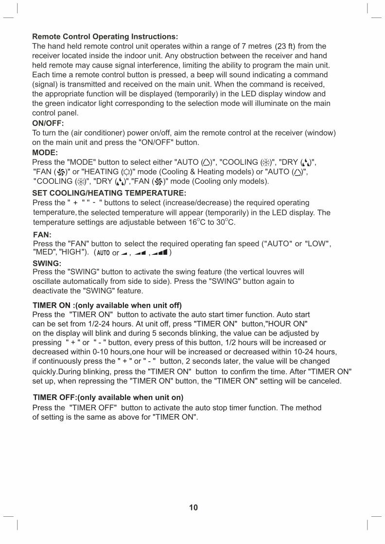
(23 ft)
TIMER OFF:(only available when unit on)Press the "TIMER OFF" button to activate the auto stop timer function. The methodof setting is the same as above for "TIMER ON".
TIMER ON :(only available when unit off)Press the "TIMER ON" button to activate the auto start timer function. Auto startcan be set from 1/2-24 hours. At unit off, press "TIMER ON" button,"HOUR ON"on the display will blink and during 5 seconds blinking, the value can be adjusted by pressing " + " or " - " button, every press of this button, 1/2 hours will be increased or decreased within 0-10 hours,one hour will be increased or decreased within 10-24 hours, if continuously press the " + " or " - " button, 2 seconds later, the value will be changed quickly.During blinking, press the "TIMER ON" button to confirm the time. After "TIMER ON" set up, when repressing the "TIMER ON" button, the "TIMER ON" setting will be canceled.

In this mode, the fan will continue to run for 1 minute after compressor shuts off.
ENERGY SAVER:(only available in "COOLING" and "DRY" mode)Press “ENERGY SAVER” to activate or disactivate the "ENERGY SAVER" Function.
Press +and - buttons simultaneously to lock or unlock the keypad. If the remote controlleris locked, the icon will be displayed on it, in that case, press any button, the mark willflicker for three times. Repress the combination to unlock.
About switch between Fahrenheit and CentigradeUnder status of unit off, press "MODE" and " - " buttons simultaneously to switch ℃ and ℉.
INTRODUCTION FOR SPECIAL FUNCTION
ABOUT LOCK
Press this button at unit On, the light on the main unit will be turned on or off. Light On is defaulted when power on.
LIGHT:
Press this button, the clock can be set up, icon blinks. Within 5 seconds, the valuecan be adjusted by pressing " + " or " - " button, if continuously press this button for 2 seconds above, in every 1/2 seconds, one minute will be increased or decreased, if you are still pressing the button after ten minutes increased or decreased, ten minutes will be increased or decreased every 1/2 seconds. Druing blinking, repress the Clock button, icon will be constantly displayed and it denotes the setting succeeded.
CLOCK

12
13

14
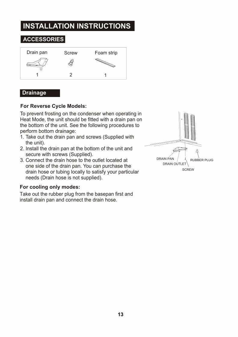
1. To avoid vibration and noise, make sure the unit is installed securely and firmly.2. Install the unit where the sunlight does not shine directly on the unit. If the unit receives direct sunlight, build an awning to shade the cabinet.3. There should be no obstacle, such as a fence or wall, within 50cm from the back of the cabinet because it will prevent heat radiation of the condenser. Restriction of outside air will greatly reduce the cooling and heating (reverse cycle models only) efficiency of the air conditioner.4. Install the unit with a slight angle down towards the rear to allow condensate to run to the (about 10mm or 1/4 bubble with level).5. Install the unit with its bottom portion 75~150cm above the floor level.6. The power cord must be connected to an independent circuit. The yellow/green wire must be earthed.7. In some light construction walls there may be a requirement for the addition of a foam or rubber strip between the air conditioner housing and the wall cavity. The addition of a foam or rubber strip will assist in isolating transmission of normal operation vibration into the wall.
rear of the air conditioner
Over 50cm
About 10mm
FENCEAWNING
75
-15
0cm
Over 50cm
About 10mm
FENCEAWNING
75
-15
0cm
All side louvres of the cabinet must not be obstructed and must be positioned outside ofthe structure.
CAUTION
Select the best location
INSTALLATION INSTRUCTIONS

Installations of the unit into the wall
AIR IN
AIR IN
AIR OUT
100mm minimum
OPTION A
AIR IN
LOUVRE
BRICKWALL
O45 BRICK CUT AWAY TO CLEAR LOUVRES
FRONT
AIR OUT
AIR INAIR INTOPVIEW
O45 BRICK CUT AWAY TO CLEAR LOUVRES
100mm
BRICKWALL
100mm
OPTION B
15
Installation of the unit into the Housing
1. Remove the front panel as per the installation instruction and slide the unit into the housing until it is firmly against the rear of the housing. Care is required to ensure the foam sealing strips on the inside of the housing remain in position. 2. Connect the air conditioner to the power and position excess cord length beneath the air conditioner base.3. Engage the chassis fixing brackets into the bottom housing rail and secure to the base with the screw provided.4. Re-install the front panel as per the installation instruction.5. Switch the unit on. Check for operation of the unit and check for vibration in the installation.6. Fit the drain pan to the housing and run a drain line to a suitable location if required.
Alternative method of installation if external support cannot be provided.
FLASH OR SEAL AROUND EXTERNAL WALL FRAME OR ARCHITRAVE
STURDY TIMBERFRAME
TIMBER FRAMED WALL OR PARTITION
SOLID TIMBER SUPPORT
STEADYING BRACKET(ONE PER SIDE)
DRAIN PAN
ENSURE LOUVRESARE ENTIRELY OUTSIDE THE WALL
Hole in the wall
Unit housingFoam strip
Step 1Remove the air conditioner from it's packaging, remove fixingscrews and slide the air conditioner out of it's housing (Referto Installation Steps).Step 2Prepare the hole in the wall so that the bottom of the housing is well supported, the top has minimum clearance and the air inlet louvres have clearance as shown in options A and B. Holes from the outside through to the cavity should be sealed.The housing should slope down towards the rear by about 10mm to allow water formed during operation to drain.
Step 3Install the housing into the wall and secure. Ensure the foam seals are not damaged. Flash, seal or fill gaps around the inside and outside to provide satisfactory appearance and protection against the weather, insects and rodents.
Note: To assist in isolating transmission of normal operation vibration into the wall, use the foam strip. Fit the foam strip between the air conditioner housing and the wall cavity.
Installation of the Housing NOTE: UNIT MAY BE SUPPORTED BY A SOLID FRAME FROM BELOW OR BY A HANGER FROM A SOLID OVERHEAD SUPPORT.
Preferred method of installation into a timber framed wall, partition or window.
FLASH OR SEAL AROUND EXTERNAL WALL FRAME OR ARCHITRAVE
STURDY TIMBERFRAME ALL AROUND UNIT
TIMBER FRAMED WALL OR PARTITION
EXTERNAL SUPPORT FRAME AT BALANCEPOINT OF A/C
ALTERNATIVELY, BRACKETS AS ILLUSTRATED IN FOLLOWINGDIAGRAM MAY BE USED.
DRAIN PAN

1. Remove the one fixing screws from the frame (See Fig.5).2. Grasp the left corner of the frame's underside, then loosen the frame and carefully disconnect the connector (See Fig.6).
1. Hold the slot under the front panel, then uplift it outwards, and remove the front panel (See Fig.3).2. Pinch the handle under the air filter and make the air filter arched, remove it from the slot from
underside to upside (See Fig.4).
Fig. 3 Fig. 4 Fig. 5
Fig. 6 Fig. 7 Fig. 8
16
In-line Connector
1. Remove the fixing screws on the chassis fixing brackets and remove the two screws on the back of cabinet (If fitted. These screws are not needed to install in later installation), then remove the chassis fixing brackets (See Fig.7).2. Grasp the handle on the chassis and carefully slide the air conditioner out of the cabinet (See Fig.8). 3. Push the unit chassis into the cabinet (See Fig.9).4. Fix the chassis with the screws previously removed as they were prior to removal.
1. Install the frame making sure not to interfere with the temperature sensor (See Fig.10).2. Fix the screws on the frame (See Fig.5). For ≥ 3.5kW/h models, the screws are supplied with the unit.
1. Install the air filter into the frame's slot from upside to underside (See Fig.4).2. Hang the front panel on the frame's buckle, then press the front panel into the frame's slot until you hear a click (See Fig11).
Fig. 9 Fig. 10 Fig. 11

Abnormal Operation
TROUBLESHOOTING
Normal Operation
Air conditioner
does not cool or
heat as it should
Air conditioner
does not start
Air conditioner
freezing up
Problem Possible Causes What To Do
The air conditioner is
unplugged.
Make sure the air conditioner plug is
pushed completely into the outlet and
switched on.
Troubleshooting Tips Save time and money! Review the chart below first and you may not need to call for service.
You may hear a pinging noise caused by water being picked up and thrown against the condenser on rainy days or when the humidity is high. This design feature helps removemoisture and improve cooling efficiency.Water will collect in the base pan during high humidity or on rainy days. The water may overflow and drip from the outdoor side of the unit.The fan may continue to operate when the compressor has cycled off.
The fuse is blown/circuit
breaker is tripped.
Check the house fuse/circuit breaker box
and replace the fuse or reset the breaker.
Power failure. If power failure occurs, switch off and
disconnect /unplug the power cord. When
power is restored, reconnect (plug in) the
power cord, switch on the power and wait
3 minutes to restart the air conditioner to
prevent tripping of the compressor overload.
Airflow is restricted .Make sure there are no curtains, blinds,
or furniture blocking the front of the air
conditioner.
Clean the filter at least every 2 weeks.
See the operating instructions section.
When the air conditioner is first turned on you
need to allow time for the room to cool down.
Check for open furnace floor registers and
cold or hot air returns.
Set the air conditioner's vent to the closed
position.
See Air Conditioner Freezing Up below.
The air filter is dirty.
The room may have been
hot.
Cold/hot air is escaping.
Coils have iced up.
Ice blocks the air flow and
stops the air conditioner
from cooling the room.
Set the fan at MED or HIGH until the
ice melts.
17

This document sets out the terms and conditions of the product warranties for Electrolux Appliances. It is an important document. Please keep it with your proof of purchase documents in a safe place for future reference should you require service for your Appliance.
1. Inthiswarranty (a) ‘acceptablequality’asreferredtoinclause10ofthiswarrantyhas
thesamemeaningreferredtointheACL; (b) ‘ACL’meansTradePracticesAmendment(AustralianConsumer
Law)Act(No.2)2010; (c) ‘Appliance’meansanyElectroluxproductpurchasedbyyou
accompaniedbythisdocument; (d) ‘ASC’meansElectrolux’authorisedservicedcentres; (e) ‘Electrolux’meansElectroluxHomeProductsPtyLtdof163
O’RiordanStreet,Mascot,NSW2020,ABN51004762341inrespectofAppliancespurchasedinAustralia;
(f) ‘majorfailure’asreferredtoinclause10ofthiswarrantyhasthesamemeaningreferredtointheACLandincludesasituationwhenanAppliancecannotberepairedoritisuneconomicforElectrolux,atitsdiscretion,torepairanApplianceduringtheWarrantyPeriod;
(g) ‘WarrantyPeriod’means: (i) wheretheApplianceisusedforpersonal,domesticorhousehold
use(i.e.normalsinglefamilyuse)assetoutintheinstructionmanual,theApplianceiswarrantedagainstmanufacturingdefectsinAustraliafor24monthsfollowingthedateoforiginalpurchaseoftheAppliance;
(ii) wheretheApplianceisusedforcommercialpurposes(includingbeingusedtodirectlyassistabusinessorwheretheApplianceisusedinamulti-familycommunalorsharetypeenvironment),theAppliancewillthenbewarrantedagainstmanufacturingdefectsinAustraliafor3months,followingthedateoforiginalpurchaseoftheAppliance.
(h) ‘you’meansthepurchaseroftheAppliancenothavingpurchasedtheApplianceforre-sale,and‘your’hasacorrespondingmeaning.
2. ThiswarrantyonlyappliestoAppliancespurchasedandusedinAustraliaandisinadditionto(anddoesnotexclude,restrict,ormodifyinanyway)anynon-excludablestatutorywarrantiesinAustralia.
3. DuringtheWarrantyPeriodElectroluxoritsASCwill,atnoextrachargeifyourApplianceisreadilyaccessibleforservice,withoutspecialequipmentandsubjecttothesetermsandconditions,repairorreplaceanypartswhichitconsiderstobedefective.ElectroluxoritsASCmayuseremanufacturedpartstorepairyourAppliance.YouagreethatanyreplacedAppliancesorpartsbecomethepropertyofElectrolux.Thiswarrantydoesnotapplytolightglobes,batteries,filtersorsimilarperishableparts.
4. PartsandAppliancesnotsuppliedbyElectroluxarenotcoveredbythiswarranty.
5. Youwillbearthecostoftransportation,travelanddeliveryoftheAppliancetoandfromElectroluxoritsASC.Ifyouresideoutsideoftheservicearea,youwillbearthecostof:
(a) travelofanauthorisedrepresentative;
(b) transportationanddeliveryoftheAppliancetoandfromElectroluxoritsASC,
Inallinstances,unlesstheApplianceistransportedbyElectroluxoranElectroluxauthorisedrepresentative,theApplianceistransportedattheowner’scostandriskwhileintransittoandfromElectroluxoritsASC.
6. Proofofpurchaseisrequiredbeforeyoucanmakeaclaimunderthiswarranty.
7. Youmaynotmakeaclaimunderthiswarrantyunlessthedefectclaimedisduetofaultyordefectivepartsorworkmanship.Electroluxisnotliableinthefollowingsituations(whicharenotexhaustive):
(a) theApplianceisdamagedby:
(i) accident
(ii) misuseorabuse,includingfailuretoproperlymaintainorservice
(iii) normalwearandtear
(iv) powersurges,electricalstormdamageorincorrectpowersupply
(v) incompleteorimproperinstallation
(vi) incorrect,improperorinappropriateoperation
(vii)insectorvermininfestation
(viii)failuretocomplywithanyadditionalinstructionssuppliedwiththeAppliance;
(b) theApplianceismodifiedwithoutauthorityfromElectroluxinwriting;
(c) theAppliance’sserialnumberorwarrantysealhasbeenremovedordefaced;
(d) theAppliancewasservicedorrepairedbyanyoneotherthanElectrolux,anauthorisedrepairerorASC.
8. Thiswarranty,thecontracttowhichitrelatesandtherelationshipbetweenyouandElectroluxaregovernedbythelawapplicablewheretheAppliancewaspurchased.
9. Totheextentpermittedbylaw,Electroluxexcludesallwarrantiesandliabilities(otherthanascontainedinthisdocument)includingliabilityforanylossordamagewhetherdirectorindirectarisingfromyourpurchase,useornonuseoftheAppliance.
10.ForAppliancesandservicesprovidedbyElectroluxinAustralia,theAppliancescomewithaguaranteebyElectroluxthatcannotbeexcludedundertheAustralianConsumerLaw.Youareentitledtoareplacementorrefundforamajorfailureandforcompensationforanyotherreasonablyforeseeablelossordamage.YouarealsoentitledtohavetheAppliancerepairedorreplacediftheAppliancefailstobeofacceptablequalityandthefailuredoesnotamounttoamajorfailure.The benefits to you given by this warranty are in addition to your other rights and remedies under a law in relation to the Appliances or services to which the warranty relates.
11.AtalltimesduringtheWarrantyPeriod,Electroluxshall,atitsdiscretion,determinewhetherrepair,replacementorrefundwillapplyifanAppliancehasavalidwarrantyclaimapplicabletoit.
12.Toenquireaboutclaimingunderthiswarranty,pleasefollowthesesteps: (a) carefullychecktheoperatinginstructions,usermanualandtheterms
ofthiswarranty; (b) havethemodelandserialnumberoftheApplianceavailable; (c) havetheproofofpurchase(eganinvoice)available; (d) telephonethenumbersshownbelow.
13.Youacceptthatifyoumakeawarrantyclaim,ElectroluxanditsASCmayexchangeinformationinrelationtoyoutoenableElectroluxtomeetitsobligationsunderthiswarranty.
WarrantyFORSALESINAUSTRALIA
APPLIANCE:WINDOWWALLAIRCONDITIONER
Important NoticeBeforecallingforservice,pleaseensurethatthestepslistedinpoint12abovehavebeenfollowed.
FOR SERVICE ortofindtheaddressofyournearest
stateservicecentreinAustraliaPLEASE CALL 13 13 49
Forthecostofalocalcall(Australiaonly)
SERVICE AUSTRALIA
ELECTROLUXHOMEPRODUCTSwww.electrolux.com.au
FOR SPARE PARTS ortofindtheaddressofyourneareststatesparepartscentreinAustralia
PLEASE CALL 13 13 50 Forthecostofalocalcall(Australiaonly)
GWWAC_Warr_Apr11
18
P/No. 1452635© 2011 Electrolux Home Products Pty Ltd ABN 51 004 762 341
Print code: KAirWWMUM_Jul11
If you’d like further information about Kelvinator appliances, please visit your retailer, phone or email our Customer Care team or visit our website.
telephone: 1300 363 640
fax: 1800 350 067
email: [email protected]
web: www.kelvinator.com.au
Kelvinator. We are part of the Electrolux family. Share more of our thinking at www.electrolux.com.au
66129909414